JP6732465B2 - Liquid ejection head and liquid ejection device - Google Patents
Liquid ejection head and liquid ejection device Download PDFInfo
- Publication number
- JP6732465B2 JP6732465B2 JP2016025785A JP2016025785A JP6732465B2 JP 6732465 B2 JP6732465 B2 JP 6732465B2 JP 2016025785 A JP2016025785 A JP 2016025785A JP 2016025785 A JP2016025785 A JP 2016025785A JP 6732465 B2 JP6732465 B2 JP 6732465B2
- Authority
- JP
- Japan
- Prior art keywords
- discharge
- liquid
- port
- supply
- discharge port
- Prior art date
- Legal status (The legal status is an assumption and is not a legal conclusion. Google has not performed a legal analysis and makes no representation as to the accuracy of the status listed.)
- Active
Links
Images


Classifications
-
- B—PERFORMING OPERATIONS; TRANSPORTING
- B41—PRINTING; LINING MACHINES; TYPEWRITERS; STAMPS
- B41J—TYPEWRITERS; SELECTIVE PRINTING MECHANISMS, i.e. MECHANISMS PRINTING OTHERWISE THAN FROM A FORME; CORRECTION OF TYPOGRAPHICAL ERRORS
- B41J2/00—Typewriters or selective printing mechanisms characterised by the printing or marking process for which they are designed
- B41J2/005—Typewriters or selective printing mechanisms characterised by the printing or marking process for which they are designed characterised by bringing liquid or particles selectively into contact with a printing material
- B41J2/01—Ink jet
- B41J2/135—Nozzles
- B41J2/14—Structure thereof only for on-demand ink jet heads
- B41J2002/14419—Manifold
-
- B—PERFORMING OPERATIONS; TRANSPORTING
- B41—PRINTING; LINING MACHINES; TYPEWRITERS; STAMPS
- B41J—TYPEWRITERS; SELECTIVE PRINTING MECHANISMS, i.e. MECHANISMS PRINTING OTHERWISE THAN FROM A FORME; CORRECTION OF TYPOGRAPHICAL ERRORS
- B41J2/00—Typewriters or selective printing mechanisms characterised by the printing or marking process for which they are designed
- B41J2/005—Typewriters or selective printing mechanisms characterised by the printing or marking process for which they are designed characterised by bringing liquid or particles selectively into contact with a printing material
- B41J2/01—Ink jet
- B41J2/135—Nozzles
- B41J2/14—Structure thereof only for on-demand ink jet heads
- B41J2002/14459—Matrix arrangement of the pressure chambers
-
- B—PERFORMING OPERATIONS; TRANSPORTING
- B41—PRINTING; LINING MACHINES; TYPEWRITERS; STAMPS
- B41J—TYPEWRITERS; SELECTIVE PRINTING MECHANISMS, i.e. MECHANISMS PRINTING OTHERWISE THAN FROM A FORME; CORRECTION OF TYPOGRAPHICAL ERRORS
- B41J2202/00—Embodiments of or processes related to ink-jet or thermal heads
- B41J2202/01—Embodiments of or processes related to ink-jet heads
- B41J2202/12—Embodiments of or processes related to ink-jet heads with ink circulating through the whole print head
Description
本発明は、液体を吐出する液体吐出ヘッドおよび液体吐出装置に関する。 The present invention relates to a liquid ejection head and a liquid ejection device that eject liquid.
液体吐出装置では、吐出口から吐出する液体を貯留する圧力室に気泡が混入すると、液体を吐出するための圧力が分散して、液体が曲がって吐出される吐出曲がりや、液体が吐出口まで供給されずに、液体が吐出されない不吐出などの不具合が生じることがある。また、液体の吐出が終了してから一定時間が経過すると、圧力室内に残存している液体の揮発成分が吐出口から蒸発することがある。この場合、圧力室内の液体の色材の濃度や液体の粘度が変化してしまい、液体の色が変化したり、吐出曲がりが発生したりするなどの不具合が生じることがある。
これに対して特許文献1には、圧力室に2本の流路が接続された液体吐出ヘッドが開示されている。この液体吐出ヘッドでは、複数の圧力室が並設された圧力室列の両隣に、圧力室列と平行して、圧力室に液体を供給するための供給共通流路と、圧力室から液体を排出するための排出共通路が設けられている。各圧力室には、供給共通流路および排出共通路のそれぞれと対向する位置に供給口および排出口を備える。各圧力室に接続された2本の流路の一方は、供給口を介して供給共通流路と連通し、圧力室に液体を供給する供給路として機能する。各圧力室に接続された2本の流路の他方は、排出口を介して排出共通路と連通し、圧力室から液体を排出する排出路として機能する。このため、圧力室内の液体を排出路を介して排出することで、圧力室内の気泡や、揮発成分が蒸発した高粘度の液体を圧力室から除去することが可能になる。
In a liquid ejecting apparatus, when air bubbles are mixed in a pressure chamber that stores the liquid ejected from the ejection port, the pressure for ejecting the liquid is dispersed, and the liquid is bent and ejected. Problems such as non-ejection in which the liquid is not ejected may be caused without being supplied. Further, when a certain period of time has passed after the discharge of the liquid was completed, the volatile component of the liquid remaining in the pressure chamber may evaporate from the discharge port. In this case, the concentration of the color material of the liquid in the pressure chamber and the viscosity of the liquid change, which may cause a problem such as a change in the color of the liquid or occurrence of ejection bending.
On the other hand,
特許文献1に記載の技術では、複数の圧力室のそれぞれに対して専用の供給口および排出口が1つずつ備わっているため、複数の吐出口のそれぞれに対して専用の供給路と排出路が1つずつ必要となる。このため、特許文献1に記載の技術では、圧力室に供給路のみが配置されている従来技術と比べて、液体吐出ヘッドにおける流路に専有されるスペースが大きくなり、その結果、液体吐出ヘッドが大型化してしまうという問題がある。
In the technique described in
本発明の目的は、吐出の不具合を軽減しつつ、大型化を抑制することが可能な液体吐出ヘッドおよび液体吐出装置を提供することである。 An object of the present invention is to provide a liquid ejecting head and a liquid ejecting apparatus capable of suppressing an increase in size while reducing ejection defects.
本発明による液体吐出ヘッドは、液体を吐出する複数の吐出口が配置された吐出口列を備える面と、各吐出口から吐出する液体を貯留する複数の圧力室と、各圧力室に液体を供給するための複数の供給口と、各圧力室から液体を排出するための複数の排出口と、を備え、前記面に直交する方向から見て、前記供給口、前記吐出口、および前記排出口がこの順に前記吐出口列の方向に沿って配置されており、前記吐出口列の方向において互いに隣接する2つの吐出口の間には前記供給口および前記排出口のうちのいずれかが設けられており、前記2つの吐出口は、前記2つの吐出口の間に設けられた前記供給口および前記排出口のうちのいずれかを共有する。一態様では、各供給口を介して各圧力室に液体を供給する供給流路と、各排出口を介して各圧力室から液体を排出する排出流路と、各供給口と前記供給流路とを連通する複数の供給連絡流路と、各排出口と前記排出流路とを連通する複数の排出連絡流路と、をさらに備え、前記吐出口列は、前記供給流路と前記排出流路で挟まれ、互いに隣接する2つの前記吐出口列の各供給口または各排出口は、当該2つの吐出口列の間にある1つの前記供給流路または前記排出流路と連通している。他の態様では、各供給口を介して各圧力室に液体を供給する供給流路と、各排出口を介して各圧力室から液体を排出する排出流路と、をさらに備え、前記供給流路および前記排出流路のそれぞれは、複数の前記吐出口列のそれぞれの前記供給口および前記排出口のそれぞれと重なるように、複数の前記吐出口列と交差し、互いに隣接する2つの前記吐出口列の各供給口および各排出口は、前記吐出口列と平行な方向にずれて配置され、前記供給流路および前記排出流路は、当該2つの吐出口列の間で、前記吐出口列と平行な方向に段差を有する。また、別の態様では、前記吐出口列の各吐出口の少なくとも1つは、前記吐出口列と垂直な方向にずれて配置され、さらに別の態様では、前記供給口および前記排出口と重なり、前記吐出口列と交差する方向に延在する流路壁をさらに備える。 A liquid ejection head according to the present invention includes a surface having an ejection port array in which a plurality of ejection ports for ejecting a liquid are arranged, a plurality of pressure chambers for storing the liquid ejected from each ejection port, and a liquid for each pressure chamber. A plurality of supply ports for supplying the liquid and a plurality of discharge ports for discharging the liquid from the pressure chambers are provided, and the supply port, the discharge port, and the discharge port when viewed from a direction orthogonal to the plane. The outlets are arranged in this order along the direction of the discharge port array, and one of the supply port and the discharge port is provided between two discharge ports adjacent to each other in the direction of the discharge port array. The two discharge ports share any one of the supply port and the discharge port provided between the two discharge ports. In one aspect, a supply flow path for supplying liquid to each pressure chamber via each supply port, a discharge flow path for discharging liquid from each pressure chamber via each discharge port, each supply port and the supply flow path. And a plurality of discharge communication flow paths communicating each discharge port with the discharge flow path, wherein the discharge port array includes the supply flow path and the discharge flow path. Each supply port or each discharge port of the two discharge port arrays adjacent to each other sandwiched by a passage communicates with one of the supply flow channel or the discharge flow channel between the two discharge port sequences. .. In another aspect, a supply flow path for supplying a liquid to each pressure chamber via each supply port, and a discharge flow path for discharging a liquid from each pressure chamber via each discharge port are further provided. Each of the passage and the discharge passage intersects with the plurality of discharge port rows so as to overlap with each of the supply port and the discharge port of each of the plurality of discharge port rows, and the two discharge ports adjacent to each other. Each of the supply ports and each of the discharge ports of the outlet row are arranged so as to be displaced in a direction parallel to the discharge port row, and the supply flow path and the discharge flow path are located between the two discharge port rows and the discharge ports. It has steps in the direction parallel to the rows. Further, in another aspect, at least one of the ejection ports of the ejection port array is arranged so as to be displaced in a direction perpendicular to the ejection port array, and in yet another aspect, overlaps with the supply port and the ejection port. Further provided is a flow path wall extending in a direction intersecting the discharge port array.
本発明によれば、圧力室から液体を排出するための排出口を有するため、圧力室内の気泡や、揮発成分が蒸発した高粘度の液体を圧力室から除去することが可能になり、その結果、吐出の不具合を軽減することが可能になる。また、供給口、吐出口、および排出口がこの順に吐出口列に沿って配置されているため、互いに隣接する供給口および排出口の間のそれぞれに吐出口が配置される。このため、互いに隣接する吐出口が供給口や排出口を共有することが可能になるため、複数の吐出口のそれぞれに対して専用の供給路と排出路を1つずつ設ける必要がなくなり、大型化を抑制することが可能になる。したがって、吐出の不具合を軽減しつつ、大型化を抑制することが可能になる。 According to the present invention, since it has the discharge port for discharging the liquid from the pressure chamber, it is possible to remove the air bubbles in the pressure chamber and the high-viscosity liquid in which the volatile component is evaporated from the pressure chamber, and as a result, Therefore, it becomes possible to reduce discharge defects. Further, since the supply port, the discharge port, and the discharge port are arranged in this order along the discharge port row, the discharge port is arranged between each of the supply port and the discharge port adjacent to each other. For this reason, since it becomes possible for adjacent ejection ports to share the supply port and the ejection port, it is not necessary to provide one dedicated supply path and one ejection path for each of the plurality of ejection ports, and it is possible to increase the size. Can be suppressed. Therefore, it is possible to suppress an increase in size while reducing discharge defects.
以下、本発明の実施形態について図面を参照して説明する。なお、各図面において同じ機能を有するものには同じ符号を付け、その説明を省略する場合がある。以下で説明する各実施形態の液体吐出ヘッドおよび液体吐出装置は、プリンタ、複写機、通信システムを有するファクシミリ、プリンタ部を有するワードプロセッサなどの装置、さらには各種処理装置と複合的に組み合わせた産業記録装置に適用可能である。産業記録装置としては、例えば、バイオチップの作製装置や、電気回路の印刷装置などが挙げられる。
(第1の実施形態)
図1ないし図5は、本発明の第1の実施形態に係る液体吐出ヘッドを示す図である。具体的には、図1は、本実施形態に係る液体吐出ヘッドの要部を示す平面透過図であり、図2は、図1の細部を拡大した拡大平面図である。図3は、図2のA−A線に沿った断面斜視図であり、図4は、図2のB−B線に沿った断面斜視図である。図5は、図2のA−A線に沿った断面図である。
図1ないし図5に示す液体吐出ヘッド100は、基板1と、基板1に接着された吐出口形成部材1aとを備える。基板1における吐出口形成部材1aが接着された面とは反対側の面には、液体が供給される供給流路2と、供給流路2と連通した複数の供給連絡流路10と、液体を排出する排出流路4と、排出流路4と連通した複数の排出連絡流路11とが形成されている。供給流路2には、液体を貯留するタンク(不図示)から液体が供給される。
基板1における吐出口形成部材1aが接着された面には、供給連絡流路10を介して供給流路2と連通した複数の供給口3と、排出連絡流路11を介して排出流路4と連通した複数の排出口5とが形成されている。以下、供給口3および排出口5を貫通口9aと総称し、供給連絡流路10および排出連絡流路11を連絡流路9bと総称することもある。本実施形態では、1つの貫通口9aに対して1つの連絡流路9bが設けられている。また、基板1における吐出口形成部材1aが接着された面には、入力された電気信号に応じて、液体を吐出するために利用されるエネルギーを発生させるエネルギー発生素子7が形成されている。
吐出口形成部材1aにおける基板1と接着された面には凹部が形成され、その凹部と、基板1上の供給口3、排出口5およびエネルギー発生素子7が対向している。凹部におけるエネルギー発生素子7と対向する箇所は、吐出する液体を貯留する圧力室6として機能し、凹部における供給口3および排出口5と対向する箇所は、供給口3を圧力室6を介して排出口5に連通する共通流路6aとして機能する。
吐出口形成部材1aにおける基板1と接着された面とは反対側の面8bには、液体を吐出するための複数の吐出口8が配置された吐出口列8bが備わっている。吐出口8は凹部と連通し、圧力室6を介して基板1上のエネルギー発生素子7と対向している。
また、図1および図2に示すように、液体吐出ヘッド100を吐出口8が形成された面8bから見た場合、複数の吐出口8が並設された吐出口列8aが複数形成されている。複数の吐出口列8aは、互いに平行に配置されている。吐出口8とエネルギー発生素子7が対向し、吐出口8とエネルギー発生素子7との間に圧力室6が設けられているため、圧力室6およびエネルギー発生素子7もそれぞれ平行な複数の列を形成している。
各吐出口列8aでは、吐出口8と貫通口9aとは交互に配置され、貫通口9aとしては、供給口3および排出口5が交互に配置される。したがって、各吐出口列8aでは、供給口3および排出口5が交互に配置され、互いに隣接する供給口3および排出口5の間のそれぞれに吐出口8が配置されている。
以上の構成により、本実施形態の液体吐出ヘッド100では、図5に示すように、供給口3から供給された液体を圧力室6を経由して排出口5から排出することで、供給口3から排出口5へ向かう方向の液体の流れが発生する。この流れが発生した状態でエネルギー発生素子7がエネルギーを発生させる。エネルギー発生素子7で発生したエネルギーは圧力室6に伝達され、そのエネルギーによって圧力室6内におけるエネルギー発生素子7の周辺の液体が加熱されて膜沸騰し、圧力室6内に気泡が形成される。この気泡の発泡圧によって、圧力室6内の液体に運動エネルギーが付与され、その液体が吐出口8から液体吐出ヘッド100の外部に吐出される。
供給口3から供給された液体のうち吐出口8から吐出されなかった液体は、圧力室6を経由して排出口5から排出される。これにより、圧力室6内に存在する液体も、液体の粘性応力によって液体の流れ方向に引きずられることになる。したがって、圧力室6内に存在する液体は、圧力室6内に発生する流れに沿って移動する。なお、排出口5から排出された液体は、不図示のフィルタによって異物が取り除かれて、タンクに戻され、再び液体吐出ヘッド100に供給されてもよい。この場合、圧力室6内の液体は外部との間で循環されることとなる。
以上説明したように、排出口5が備わっているため、圧力室6内の液体を流れることで、圧力室6内に液体が滞留することを抑制することができる。このため、圧力室6に混入した気泡を排出することができるため、吐出圧力の分散による吐出曲がりや液体の吐出口8への未供給による不吐出など、圧力室6内に存在する気泡に起因する不具合を抑制することが可能になる。また、液体に含まれる揮発成分が吐出口8から蒸発することによって発生する、吐出口8近傍の液体の増粘および色材濃度の変化や、吐出口8への液体の含有成分の固着のような、記録画像の画質低下を引き起こす不具合も抑制することができる。
また、吐出口列8aにおいて、供給口3と排出口5とが交互に配置され、互いに隣接する供給口3および排出口5の間のそれぞれに吐出口8が配置される。すなわち、吐出口8を備える面8bに直交する方向から見て、供給口3、吐出口8、排出口5がこの順に吐出口列8aの方向に沿って配置されている。このため、互いに隣接する吐出口8が供給口3や排出口5を共有することが可能になるため、吐出口8ごとに供給連絡流路10と排出連絡流路11の両方を設ける必要がなくなる。したがって、液体吐出ヘッド100の大型化を抑制することが可能になる。
以上のように本実施形態では、吐出の不具合を軽減しつつ、大型化を抑制することが可能になる。つまり、高品位な画像形成を可能にしつつ、基板1のサイズの小さい液体吐出ヘッド100を実現することができる。
Embodiments of the present invention will be described below with reference to the drawings. In each drawing, components having the same function are designated by the same reference numeral, and the description thereof may be omitted. A liquid ejection head and a liquid ejection device of each embodiment described below are industrial recordings that are combined with a device such as a printer, a copying machine, a facsimile having a communication system, a word processor having a printer unit, and various processing devices. Applicable to devices. Examples of the industrial recording device include a biochip manufacturing device and an electric circuit printing device.
(First embodiment)
1 to 5 are views showing a liquid ejection head according to a first embodiment of the present invention. Specifically, FIG. 1 is a plan transparent view showing a main part of the liquid ejection head according to the present embodiment, and FIG. 2 is an enlarged plan view in which the details of FIG. 1 are enlarged. 3 is a sectional perspective view taken along the line AA of FIG. 2, and FIG. 4 is a sectional perspective view taken along the line BB of FIG. FIG. 5 is a cross-sectional view taken along the line AA of FIG.
The
On the surface of the
A recess is formed on the surface of the discharge
A
As shown in FIGS. 1 and 2, when the
In each
With the configuration described above, in the
Of the liquid supplied from the
As described above, since the
Further, in the
As described above, in the present embodiment, it is possible to suppress the problem of ejection and suppress the increase in size. That is, it is possible to realize the
以下、液体吐出ヘッド100の流路構成についてより詳細に説明する。
図2および図5に示したように本実施形態では、供給流路2および排出流路4のそれぞれが吐出口列8aと平行に配置されている。また、供給連絡流路10が供給口3と供給流路2とを連通し、排出連絡流路11とが排出口5と排出流路4とを連通することで、供給流路2および排出流路4が圧力室6を介して互いに連通している。これにより、圧力室6内の液体を循環させることが可能になっている。
本構成において、複数の吐出口列8aを液体吐出ヘッド100に配置する場合、液体吐出ヘッド100の流路構成は、以下の個別構成と共通構成のいずれかを採用することができる。個別構成は、互いに隣接する吐出口列8aのそれぞれに対して供給流路2および排出流路4を個別に設ける構成であり、共通構成は、互いに隣接する吐出口列8aに対して供給流路2および排出流路4の一方が共通化されている構成である。個別構成の場合、互いに隣接する吐出口列8aの間に、個別に設けられる各流路を隔てる壁が形成されるため、基板1の強度を高くすることができる。一方、共通構成の場合、互いに隣接する吐出口8の列の間の距離を短くすることができるため、基板1の更なる小型化を図ることが可能になる。なお、図1ないし図5で示した構成は、個別構成である。
図6は、個別構成の液体吐出ヘッド100における流路の配置例を示す平面透過図である。
個別構成では、供給流路2および排出流路4が交互に並ぶ構成と、供給流路2同士または排出流路4同士が隣接する構成のいずれかを採用することができる。図6(a)および(b)では、供給流路2および排出流路4が交互に並ぶ構成が示されており、図6(c)および図6(d)では、排出流路4同士が隣接する構成が示されている。なお、供給流路2および排出流路4がそれぞれ3つ以上ある場合、これらの構成の一方のみでなく、これらの構成が混在するように供給流路2および排出流路4が配置されてもよい。
上記の構成のいずれの場合でも、連絡流路9bである供給連絡流路10および排出連絡流路11は、複数の吐出口列8aのそれぞれにおいて、吐出口列8aと平行な方向に交互に配置されている。連絡流路9bの形状や向きは吐出口列8aごとに異なっていてもよい。図6(a)および図6(c)では、吐出口列8aと垂直な方向において互いに隣接する2つの連絡流路9bが互いに同じ向きに延在している。また、図6(b)および図6(d)では、吐出口列8aと垂直な方向において互いに隣接する連絡流路9bが互いに逆向きに延在している。
図7は、個別構成の液体吐出ヘッド100における流路の別の配置例を示す平面透過図である。
図7(a)の例では、供給流路2および排出流路4が交互に並び、図7(b)の例では、排出流路4同士が隣接している。これらの構成の違いに関わらず、図7(a)および図7(b)の例では、互いに隣接する吐出口列8aがその吐出口列8aに平行な方向にずれて配置されている。この構成の場合、記録される画像の解像度を向上させることができる。
例えば、吐出口列8a内の吐出口8の配置間隔であるピッチ幅をPとしたとき、互いに隣接する吐出口列8aが、吐出口列8aに平行な方向について互いにズレ幅Pa=P/2でずれていたとする。この場合、ズレ幅Paに応じて2倍の解像度を実現することができる。ズレ幅PaはP/2以下にしてもよい。一般にズレ幅PaをP/nとすることで、n倍の解像度を実現することができる。nは、2以上の整数である。
図8および図9は、共通構成の液体吐出ヘッド100における流路の配置例を示す平面透過図である。
図8の例では、共通構成において、互いに隣接する吐出口列8aがその吐出口列8aに平行な方向にずれずに配置されている。図8(a)では、吐出口列8aと垂直な方向において互いに隣接する2つの連絡流路9bが互いに逆向きに延在している。また、図8(b)では、吐出口列8aと垂直な方向において互いに隣接する連絡流路9bが互いに同じ向きに延在している。
図9に示す液体吐出ヘッド100は、共通構成において、互いに隣接する吐出口列8aがその吐出口列8aに平行な方向にずれて配置されている構成である。この構成の場合でも、図7の例と同様に、記録される画像の解像度を向上させることができる。
図10は、本実施形態の液体吐出ヘッド100における流路の別の配置例を示す平面透過図である。
図1ないし図9の例では、吐出口列8aの中心線Cと、供給流路2の中心線Dおよび排出流路4の中心線Eとが互いに平行であった。これに対して、図10(a)の例では、供給流路2の中心線Dおよび排出流路4の中心線Eが吐出口列8aの中心線Cに対して傾いている。なお、供給流路2の中心線Dおよび排出流路4の中心線Eは、図10(a)では、互いに平行であるが、互いに傾いていてもよい。この場合、吐出口列8aの中心線Cは、供給流路2の中心線Dおよび排出流路4の中心線Eの一方に対して傾いていればよい。
また、図1ないし図9の例では、吐出口列8aの各吐出口8は、吐出口列8aと垂直な方向に対しては揃って配置されていた。具体的には、吐出口列8aの各吐出口8の中心が、互いに隣接する供給流路2および排出流路4に挟まれた領域の中心線Fの上に並んでいた。これに対して図10(b)の例では、吐出口列8aの各吐出口8の少なくとも1つは、吐出口列8aと垂直な方向に対してずれて配置されている。つまり、吐出口列8aの各吐出口8は、互いに隣接する供給流路2および排出流路4に挟まれた領域の中心線Fから吐出口8の少なくとも1つが外れて並設されている。この場合、吐出口列8aの各吐出口8から液体を吐出するタイミングに差をつける時間分割駆動に対する適合性を向上させることができる。
以上で説明した各変形例においても、排出口5が備わり、吐出口列8aにおける供給口3と排出口5との間のそれぞれに吐出口8が設けられるため、吐出の不具合を軽減しつつ、大型化を抑制することが可能になる。つまり、高品位な画像形成を可能にしつつ、基板1のサイズの小さい液体吐出ヘッド100を実現することができる。
Hereinafter, the flow path configuration of the
As shown in FIGS. 2 and 5, in the present embodiment, each of the
In the present configuration, when the plurality of
FIG. 6 is a transparent plan view showing an example of the arrangement of flow paths in the
In the individual configuration, it is possible to employ either a configuration in which the
In any of the above configurations, the supply
FIG. 7 is a transparent plan view showing another arrangement example of the flow paths in the
In the example of FIG. 7A, the
For example, when the pitch width that is the arrangement interval of the
8 and 9 are plan transparent views showing an example of the arrangement of flow paths in the
In the example of FIG. 8, in the common configuration, the
The
FIG. 10 is a plan view showing another arrangement example of the flow paths in the
In the examples of FIGS. 1 to 9, the center line C of the
Further, in the examples of FIGS. 1 to 9, the
Also in each of the modified examples described above, the
(第2の実施形態)
図11ないし図13は、本発明の第2の実施形態に係る液体吐出ヘッドを示す図である。具体的には、図11は、本実施形態に係る液体吐出ヘッドの要部を示す平面透過図であり、図12および図13は、図11の細部を拡大した拡大平面図である。
図11に示す液体吐出ヘッド101は、図1ないし図10で示した第1の実施形態の液体吐出ヘッド100と比べて、複数の供給流路2および複数の排出流路4が吐出口列8aと交差する方向に延在している点で異なる。供給流路2および排出流路4は、具体的には、図12で詳細に示すように供給流路2および排出流路4が吐出口列8aと垂直な方向に延在している。また、図11に示す液体吐出ヘッド101は、第1の実施形態で示した供給連絡流路10および排出連絡流路11がなく、供給共通流路12と排出共通流路13とを新たに備えている。
図13で詳細に示すように、各供給流路2は、複数の吐出口8が配置された面8bに対して垂直な方向において、複数の吐出口列8aのそれぞれの供給口3と重なっている。また、各排出流路4は、複数の吐出口8が配置された面8bに対して垂直な方向において、複数の吐出口列8aのそれぞれの排出口5と重なっている。このため、図11に示す液体吐出ヘッド101は、第1の実施形態(図1〜図10)で示した供給連絡流路10および排出連絡流路11がなくても、供給流路2から供給口3に液体を供給し、排出口5から排出流路4に液体が排出される。
供給共通流路12および排出共通流路13は、吐出口列8aと平行な方向に延在し、全ての吐出口列8aを挟むように配置される。供給共通流路12は、複数の供給流路2と連通し、各供給流路2に液体を供給し、排出共通流路13は、複数の排出流路4と連通し、各排出流路4から液体を記録ヘッドの外部に排出する。
以上の構成により、互いに隣接する吐出口列8aの間に供給流路2および排出流路4を配置しなくてもよくなるため、吐出口列8aの間隔を短くすることが可能になり、基板1の大型化をさらに抑制することが可能になる。
(Second embodiment)
11 to 13 are views showing a liquid ejection head according to the second embodiment of the present invention. Specifically, FIG. 11 is a plan transparent view showing a main part of the liquid ejection head according to the present embodiment, and FIGS. 12 and 13 are enlarged plan views in which the details of FIG. 11 are enlarged.
The
As shown in detail in FIG. 13, each
The
With the above configuration, it is not necessary to dispose the
図14ないし図16は、本実施形態の液体吐出ヘッド101における流路の別の配置例を示す平面透過図である。
図14の例では、互いに隣接する吐出口列8aがその吐出口列8aに平行な方向にずれて配置されている。このため、互いに隣接する2つの吐出口列8aのそれぞれの供給口3および排出口5は、吐出口列8aと平行な方向にずれて配置される。供給流路2および排出流路4は、吐出口列8aと直交せずに交差する方向に延在している。具体的には、供給流路2は、互いに隣接する2つの吐出口列8aのそれぞれの2つの供給口3を結ぶ直線上に設けられ、排出流路4は、互いに隣接する2つの吐出口列のそれぞれの2つの排出口5を結ぶ直線上に設けられる。
図14の例の場合、互いに隣接する吐出口列8aがその吐出口列8aに平行な方向について互いにずれていても、供給流路2および排出流路4を複数の吐出口列8aのそれぞれに配置された複数の供給口3および複数の排出口5と連通させることができる。このため、基板1の大型化を抑制しながら、解像度を増加させることが可能になる。
図15の例では、互いに隣接する吐出口列8aがその吐出口列8aに平行な方向にずれて配置されている。このため、互いに隣接する2つの吐出口列8aのそれぞれの供給口3および排出口5は、吐出口列8aと平行な方向にずれて配置される。供給流路2および排出流路4は、互いに隣接する吐出口列8aの間で、吐出口列8aと平行な方向に段差を有する。
具体的には、図15(a)の例では、吐出口列8aと平行な方向の位置が異なる供給流路2および排出流路4が互いに隣接する吐出口列8aの間で接続されることで、供給流路2および排出流路4に段差が付けられている。このとき、供給流路2および排出流路4のズレ幅は、供給流路2および排出流路4の内径未満である。図15(b)の例では、供給流路2および排出流路4が互いに隣接する吐出口列8aの間で階段形状を有しており、図15(c)の例では、互いに隣接する吐出口列8aの間で、供給流路2および排出流路4が傾斜している。
図15の例でも、図14の例と同様な効果が得られる。つまり、図15の例でも、互いに隣接する吐出口列8aがその吐出口列8aに平行な方向について互いにずれていても、供給流路2および排出流路4を複数の吐出口列8aのそれぞれに配置された複数の供給口3および複数の排出口5と連通させることができる。このため、基板1の大型化を抑制しながら、解像度を増加させることが可能になる。
図16の例では、吐出口列8aの各吐出口は、互いに隣接する複数の供給口3および複数の排出口5の中心を結ぶ中心線Fから吐出口8の少なくとも1つが外れて並設されている。この場合、吐出口列8aの各吐出口8から液体を吐出するタイミングに差をつける時間分割駆動に対する適合性を向上させることができる。なお、吐出口列8aと供給流路2および排出流路4とが交わっていればよく、直交していなくてもよい。
14 to 16 are plan transparent views showing another arrangement example of the flow paths in the
In the example of FIG. 14, the
In the case of the example of FIG. 14, even if the
In the example of FIG. 15, the
Specifically, in the example of FIG. 15A, the
Also in the example of FIG. 15, the same effect as that of the example of FIG. 14 can be obtained. That is, also in the example of FIG. 15, even if the
In the example of FIG. 16, the respective ejection ports of the
以上で説明した本実施形態でも、第1の実施形態と同様に、排出口5が備わり、吐出口列8aにおける供給口3と排出口5との間のそれぞれに吐出口8が設けられるため、吐出の不具合を軽減しつつ、大型化を抑制することが可能になる。
また、複数の供給流路2および複数の排出流路4が吐出口列8aと交差する方向に延在しているため、互いに隣接する吐出口列8aの間に供給流路2および排出流路4を配置しなくてもよくなる。したがって、吐出口列8aの間隔を短くすることが可能になり、基板1の大型化をさらに抑制することが可能になる。
Also in the present embodiment described above, as in the first embodiment, the
Further, since the plurality of
(第3の実施形態)
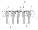
図17および図18は、本発明の第3の実施形態に係る液体吐出ヘッドを示す図である。具体的には、図1は、本実施形態に係る液体吐出ヘッドの要部を示す平面透過図であり、図18は、図17のH−H線に沿った断面図である。
図17および図18に示す液体吐出ヘッド102は、第1の実施形態の液体吐出ヘッド100と比べて、複数の流路壁14をさらに備える点で異なる。各流路壁14は、複数の吐出口8が配置された面8bに対して垂直な方向において供給口3および排出口5と重なり、吐出口列8aと交差する方向に延在する。図17および図18の例では、流路壁14は、供給口3および排出口5のそれぞれの直上を吐出口列8aと直交する方向に延在する。
本実施形態でも、第1の実施形態と同様に、排出口5が備わり、吐出口列8aにおける供給口3と排出口5との間のそれぞれに吐出口8が設けられるため、吐出の不具合を軽減しつつ、大型化を抑制することが可能になる。
また、各圧力室6が流路壁14によって分割されるため、液体を吐出する際に圧力室6内で生じる発泡が隣接する圧力室6に及ぼす影響を流路壁14によって緩和することが可能になる。したがって、吐出による圧力室6間の干渉であるクロストークを抑制することが可能になる。
(Third Embodiment)
17 and 18 are diagrams showing a liquid ejection head according to the third embodiment of the present invention. Specifically, FIG. 1 is a plan view showing a main part of the liquid ejection head according to the present embodiment, and FIG. 18 is a cross-sectional view taken along line HH of FIG.
The
In the present embodiment as well, as in the first embodiment, the
Further, since each
(液体吐出装置)
図19および図20は、上述の実施形態の液体吐出ヘッドを装着可能な液体吐出装置を説明するための図である。具体的には、図19は、液体吐出装置の機械的な構成を示す外観斜視図であり、図20は、液体の供給系の示した概念図である。
図19に示す液体吐出装置200は、記録媒体に液体を吐出して記録媒体上に画像を記録する記録装置である。液体吐出装置200は、液体吐出装置の枠組みを形成するシャーシ40を備える。シャーシ40は、所定の剛性を有する複数の板状金属部材で構成される。シャーシ40には、記録媒体給送部41と、記録媒体搬送部42と、液体吐出ヘッド43とが組み付けられている。記録媒体給送部41は、記録媒体(不図示)を液体吐出装置200の内部に給送する。記録媒体は、例えば、紙などのシート状の部材である。記録媒体は、連続したロール形状のものでも、カットされた形状ものでもよい。記録媒体搬送部42は、記録媒体給送部41にて給送された記録媒体を図の矢印の方向Xに沿って、画像を記録するための記録位置に導く。液体吐出ヘッド43は、第1ないし第3の実施形態で説明した液体吐出ヘッド100〜102のいずれかであり、インクのような液体を吐出する。記録位置は、液体吐出ヘッド43から吐出される液体が着弾可能な位置である。液体吐出ヘッド43は、記録媒体搬送部42にて記録位置まで搬送された記録媒体に対して液体を吐出して、記録媒体上に画像を記録する。
また、図20で示すように液体吐出装置は、液体を貯留する液体タンク44および45を備える。液体タンク44は、液体吐出ヘッド43に供給する液体を貯留し、液体タンク45は、液体吐出ヘッド43から排出された液体を貯留する。液体タンク44内の液体は、液体タンク44と液体吐出ヘッド43を連通する不図示の共通流路を介して液体吐出ヘッド43に供給される。液体吐出ヘッド43から排出された液体は、液体吐出ヘッド43と液体タンク45とを連通する不図示の共通流路を介して液体タンク45に回収される。
液体吐出ヘッド43に対する液体の供給および排出を行う供給・排出方法は、特に限定されない。例えば、供給・排出方法は、液体タンク44および45の水頭差を用いる方法でも、液体タンク44および45内の圧力差を制御する方法でも、ポンプなどを用いて液体に流動を生じさせる方法でもよい。液体吐出ヘッド43に対する液体の供給および排出は、液体吐出ヘッドへの液体の初期充填を行う場合や、画像を記録する場合などに行われる。
以上説明したように本実施形態の液体吐出装置200では、液体吐出ヘッド43内に液体の循環流を生じさせることが可能になる。したがって、液体吐出ヘッド43内の気泡や高粘度の液体などを排出することが可能になるため、吐出の不具合を軽減することが可能になり、その結果、高品位な画像形成が可能となる。
(Liquid discharge device)
19 and 20 are diagrams for explaining a liquid ejection apparatus to which the liquid ejection head according to the above-described embodiment can be mounted. Specifically, FIG. 19 is an external perspective view showing the mechanical configuration of the liquid ejection device, and FIG. 20 is a conceptual diagram showing a liquid supply system.
A
Further, as shown in FIG. 20, the liquid ejection device includes
The supply/discharge method for supplying and discharging the liquid to/from the
As described above, in the
以上説明した各実施形態において、図示した構成は単なる一例であって、本発明はその構成に限定されるものではない。例えば、第2の実施形態の液体吐出ヘッド101に、第3の実施形態で示した流路壁14を設けてもよい。
In each embodiment described above, the illustrated configuration is merely an example, and the present invention is not limited to the configuration. For example, the
2 供給流路
3 供給口
4 排出流路
5 排出口
6 圧力室
8 吐出口
8a 吐出口列
8b 吐出口列が配置された面
10 供給連絡流路
11 排出連絡流路
14 流路壁
43、100〜102 液体吐出ヘッド
200 液体吐出装置
2
Claims (7)
前記面に直交する方向から見て、前記供給口、前記吐出口、および前記排出口がこの順に前記吐出口列の方向に沿って配置されており、前記吐出口列の方向において互いに隣接する2つの吐出口の間には前記供給口および前記排出口のうちのいずれかが設けられており、前記2つの吐出口は、前記2つの吐出口の間に設けられた前記供給口および前記排出口のうちのいずれかを共有する、液体吐出ヘッドであって、
各供給口を介して各圧力室に液体を供給する供給流路と、各排出口を介して各圧力室から液体を排出する排出流路と、各供給口と前記供給流路とを連通する複数の供給連絡流路と、各排出口と前記排出流路とを連通する複数の排出連絡流路と、をさらに備え、
前記吐出口列は、前記供給流路と前記排出流路で挟まれ、互いに隣接する2つの前記吐出口列の各供給口または各排出口は、当該2つの吐出口列の間にある1つの前記供給流路または前記排出流路と連通していることを特徴とする液体吐出ヘッド。 A surface having a discharge port array in which a plurality of discharge ports for discharging a liquid are arranged, a plurality of pressure chambers for storing the liquid discharged from each discharge port, and a plurality of supply ports for supplying a liquid to each pressure chamber. And a plurality of discharge ports for discharging the liquid from each pressure chamber,
When viewed from the direction orthogonal to the plane, the supply port, the discharge port, and the discharge port are arranged in this order along the direction of the discharge port array, and are adjacent to each other in the direction of the discharge port array. One of the supply port and the discharge port is provided between two discharge ports, and the two discharge ports are the supply port and the discharge port provided between the two discharge ports. A liquid ejection head that shares one of the
A supply flow path for supplying a liquid to each pressure chamber via each supply port, a discharge flow path for discharging a liquid from each pressure chamber via each discharge port, and a connection between each supply port and the supply flow path. Further comprising a plurality of supply communication flow paths, a plurality of discharge communication flow paths communicating each discharge port and the discharge flow path,
The discharge port array is sandwiched between the supply flow channel and the discharge flow channel, and each supply port or each discharge port of the two discharge port arrays adjacent to each other is one between the two discharge port arrays. A liquid ejection head, which is in communication with the supply flow path or the discharge flow path .
前記面に直交する方向から見て、前記供給口、前記吐出口、および前記排出口がこの順に前記吐出口列の方向に沿って配置されており、前記吐出口列の方向において互いに隣接する2つの吐出口の間には前記供給口および前記排出口のうちのいずれかが設けられており、前記2つの吐出口は、前記2つの吐出口の間に設けられた前記供給口および前記排出口のうちのいずれかを共有する、液体吐出ヘッドであって、
各供給口を介して各圧力室に液体を供給する供給流路と、各排出口を介して各圧力室から液体を排出する排出流路と、をさらに備え、
前記供給流路および前記排出流路のそれぞれは、複数の前記吐出口列のそれぞれの前記供給口および前記排出口のそれぞれと重なるように、複数の前記吐出口列と交差し、
互いに隣接する2つの前記吐出口列の各供給口および各排出口は、前記吐出口列と平行な方向にずれて配置され、前記供給流路および前記排出流路は、当該2つの吐出口列の間で、前記吐出口列と平行な方向に段差を有することを特徴とする液体吐出ヘッド。 A surface having a discharge port array in which a plurality of discharge ports for discharging a liquid are arranged, a plurality of pressure chambers for storing the liquid discharged from each discharge port, and a plurality of supply ports for supplying a liquid to each pressure chamber. And a plurality of discharge ports for discharging the liquid from each pressure chamber,
When viewed from the direction orthogonal to the plane, the supply port, the discharge port, and the discharge port are arranged in this order along the direction of the discharge port array, and are adjacent to each other in the direction of the discharge port array. One of the supply port and the discharge port is provided between two discharge ports, and the two discharge ports are the supply port and the discharge port provided between the two discharge ports. A liquid ejection head that shares one of the
A supply flow path for supplying a liquid to each pressure chamber via each supply port, and a discharge flow path for discharging a liquid from each pressure chamber via each discharge port,
Each of the supply flow path and the discharge flow path intersects with the plurality of discharge port arrays so as to overlap with each of the supply ports and the discharge ports of the plurality of discharge port arrays,
The supply ports and the discharge ports of the two discharge port arrays that are adjacent to each other are arranged so as to be displaced in a direction parallel to the discharge port array, and the supply flow channel and the discharge flow channel are the two discharge port arrays. between the liquid discharge head characterized by having a step on the ejection port array and parallel directions.
前記面に直交する方向から見て、前記供給口、前記吐出口、および前記排出口がこの順に前記吐出口列の方向に沿って配置されており、前記吐出口列の方向において互いに隣接する2つの吐出口の間には前記供給口および前記排出口のうちのいずれかが設けられており、前記2つの吐出口は、前記2つの吐出口の間に設けられた前記供給口および前記排出口のうちのいずれかを共有する、液体吐出ヘッドであって、
前記吐出口列の各吐出口の少なくとも1つは、前記吐出口列と垂直な方向にずれて配置されることを特徴とする液体吐出ヘッド。 A surface having a discharge port array in which a plurality of discharge ports for discharging a liquid are arranged, a plurality of pressure chambers for storing the liquid discharged from each discharge port, and a plurality of supply ports for supplying a liquid to each pressure chamber. And a plurality of discharge ports for discharging the liquid from each pressure chamber,
When viewed from the direction orthogonal to the plane, the supply port, the discharge port, and the discharge port are arranged in this order along the direction of the discharge port array, and are adjacent to each other in the direction of the discharge port array. One of the supply port and the discharge port is provided between two discharge ports, and the two discharge ports are the supply port and the discharge port provided between the two discharge ports. A liquid ejection head that shares one of the
Wherein at least one of the outlet of the discharge port array is a liquid discharge head you being disposed offset in the ejection port array and perpendicular directions.
前記面に直交する方向から見て、前記供給口、前記吐出口、および前記排出口がこの順に前記吐出口列の方向に沿って配置されており、前記吐出口列の方向において互いに隣接する2つの吐出口の間には前記供給口および前記排出口のうちのいずれかが設けられており、前記2つの吐出口は、前記2つの吐出口の間に設けられた前記供給口および前記排出口のうちのいずれかを共有する、液体吐出ヘッドであって、
前記供給口および前記排出口と重なり、前記吐出口列と交差する方向に延在する流路壁をさらに備えることを特徴とする液体吐出ヘッド。 A surface having a discharge port array in which a plurality of discharge ports for discharging a liquid are arranged, a plurality of pressure chambers for storing the liquid discharged from each discharge port, and a plurality of supply ports for supplying a liquid to each pressure chamber. And a plurality of discharge ports for discharging the liquid from each pressure chamber,
When viewed from the direction orthogonal to the plane, the supply port, the discharge port, and the discharge port are arranged in this order along the direction of the discharge port array, and are adjacent to each other in the direction of the discharge port array. One of the supply port and the discharge port is provided between two discharge ports, and the two discharge ports are the supply port and the discharge port provided between the two discharge ports. A liquid ejection head that shares one of the
The supply port and overlapped with the discharge port, the liquid discharge head you further comprising a channel wall extending in a direction crossing the ejection opening array.
前記圧力室内の液体は前記供給口および前記排出口を介して前記圧力室の外部との間で循環されることを特徴とする請求項1ないし5のいずれか1項に記載の液体吐出ヘッド。 The pressure chamber is provided with an element that generates energy used to eject the liquid,
Liquid discharge head according to any one of claims 1 to 5 wherein the pressure chamber of the liquid characterized in that it is circulated between the outside of the pressure chamber through the supply port and the discharge port.
Priority Applications (1)
| Application Number | Priority Date | Filing Date | Title |
|---|---|---|---|
| JP2016025785A JP6732465B2 (en) | 2016-02-15 | 2016-02-15 | Liquid ejection head and liquid ejection device |
Applications Claiming Priority (1)
| Application Number | Priority Date | Filing Date | Title |
|---|---|---|---|
| JP2016025785A JP6732465B2 (en) | 2016-02-15 | 2016-02-15 | Liquid ejection head and liquid ejection device |
Publications (3)
| Publication Number | Publication Date |
|---|---|
| JP2017144571A JP2017144571A (en) | 2017-08-24 |
| JP2017144571A5 JP2017144571A5 (en) | 2019-03-14 |
| JP6732465B2 true JP6732465B2 (en) | 2020-07-29 |
Family
ID=59682476
Family Applications (1)
| Application Number | Title | Priority Date | Filing Date |
|---|---|---|---|
| JP2016025785A Active JP6732465B2 (en) | 2016-02-15 | 2016-02-15 | Liquid ejection head and liquid ejection device |
Country Status (1)
| Country | Link |
|---|---|
| JP (1) | JP6732465B2 (en) |
Families Citing this family (5)
| Publication number | Priority date | Publication date | Assignee | Title |
|---|---|---|---|---|
| WO2019078868A1 (en) * | 2017-10-19 | 2019-04-25 | Hewlett-Packard Development Company, L.P. | Fluidic dies |
| CN111372782B (en) * | 2017-11-27 | 2021-10-29 | 惠普发展公司,有限责任合伙企业 | Cross-die recirculation channel and chamber recirculation channel |
| EP3733414B1 (en) * | 2017-12-28 | 2022-04-20 | Konica Minolta, Inc. | Ink jet head and ink jet recording apparatus |
| US11325379B2 (en) | 2018-03-12 | 2022-05-10 | Hewlett-Packard Development Company, L.P. | Fluid ejection dies |
| JP7131478B2 (en) * | 2019-05-21 | 2022-09-06 | セイコーエプソン株式会社 | Liquid ejecting head and liquid ejecting apparatus |
Family Cites Families (6)
| Publication number | Priority date | Publication date | Assignee | Title |
|---|---|---|---|---|
| JP2010214847A (en) * | 2009-03-18 | 2010-09-30 | Fujifilm Corp | Liquid droplet ejection head and image forming apparatus |
| JP2015036238A (en) * | 2013-08-15 | 2015-02-23 | 富士フイルム株式会社 | Liquid discharge head and ink jet recorder |
| JP6272002B2 (en) * | 2013-12-18 | 2018-01-31 | キヤノン株式会社 | Liquid discharge head and liquid discharge apparatus |
| JP2015150881A (en) * | 2014-02-19 | 2015-08-24 | 京セラ株式会社 | Liquid discharge head and recording device using the same |
| US10259218B2 (en) * | 2014-02-25 | 2019-04-16 | Funai Electric Co., Ltd. | Ejection device for inkjet printers |
| CN204054949U (en) * | 2014-09-23 | 2014-12-31 | 广州市爱司凯科技股份有限公司 | A kind of nozzle ink chamber flow passage structure |
-
2016
- 2016-02-15 JP JP2016025785A patent/JP6732465B2/en active Active
Also Published As
| Publication number | Publication date |
|---|---|
| JP2017144571A (en) | 2017-08-24 |
Similar Documents
| Publication | Publication Date | Title |
|---|---|---|
| JP6732465B2 (en) | Liquid ejection head and liquid ejection device | |
| KR102139115B1 (en) | Liquid discharge head and head unit using the same | |
| US9789686B2 (en) | Liquid ejecting head and liquid ejecting apparatus | |
| JP7019328B2 (en) | Liquid discharge head | |
| JP7031687B2 (en) | Inkjet head and inkjet recording device | |
| JP7135677B2 (en) | Head unit and liquid ejector | |
| JP6808347B2 (en) | Liquid discharge head and liquid discharge device | |
| US10059099B2 (en) | Liquid ejecting head and liquid ejecting apparatus | |
| JP2019171751A (en) | Liquid discharge head | |
| JP6349649B2 (en) | Liquid ejection device | |
| EP3476606A1 (en) | Fluid ejection head and fluid ejection apparatus | |
| EP3636438B1 (en) | Inkjet head and inkjet recording device | |
| JP6569776B2 (en) | Liquid ejection device | |
| JP5832272B2 (en) | Liquid discharge head | |
| JP6708414B2 (en) | Liquid ejection head, liquid ejection device, and method for manufacturing liquid ejection head | |
| JP7347012B2 (en) | Liquid ejection device and support | |
| JP2017124601A (en) | Liquid discharge head and liquid discharge device | |
| JP2007190740A (en) | Liquid droplet ejecting apparatus | |
| JP7371343B2 (en) | liquid discharge head | |
| JP7091117B2 (en) | Liquid discharge head and recording device | |
| JP7434997B2 (en) | Liquid ejection head and liquid ejection device | |
| JP7363224B2 (en) | liquid discharge device | |
| JP7293884B2 (en) | liquid ejection head | |
| JP6750843B2 (en) | Liquid ejection head | |
| JP7351143B2 (en) | liquid discharge device |
Legal Events
| Date | Code | Title | Description |
|---|---|---|---|
| A521 | Written amendment |
Free format text: JAPANESE INTERMEDIATE CODE: A523 Effective date: 20190204 |
|
| A621 | Written request for application examination |
Free format text: JAPANESE INTERMEDIATE CODE: A621 Effective date: 20190204 |
|
| A977 | Report on retrieval |
Free format text: JAPANESE INTERMEDIATE CODE: A971007 Effective date: 20191113 |
|
| A131 | Notification of reasons for refusal |
Free format text: JAPANESE INTERMEDIATE CODE: A131 Effective date: 20191210 |
|
| A521 | Written amendment |
Free format text: JAPANESE INTERMEDIATE CODE: A523 Effective date: 20200130 |
|
| TRDD | Decision of grant or rejection written | ||
| A01 | Written decision to grant a patent or to grant a registration (utility model) |
Free format text: JAPANESE INTERMEDIATE CODE: A01 Effective date: 20200609 |
|
| A61 | First payment of annual fees (during grant procedure) |
Free format text: JAPANESE INTERMEDIATE CODE: A61 Effective date: 20200708 |
|
| R151 | Written notification of patent or utility model registration |
Ref document number: 6732465 Country of ref document: JP Free format text: JAPANESE INTERMEDIATE CODE: R151 |