JP6724888B2 - Equipment temperature controller - Google Patents
Equipment temperature controller Download PDFInfo
- Publication number
- JP6724888B2 JP6724888B2 JP2017235120A JP2017235120A JP6724888B2 JP 6724888 B2 JP6724888 B2 JP 6724888B2 JP 2017235120 A JP2017235120 A JP 2017235120A JP 2017235120 A JP2017235120 A JP 2017235120A JP 6724888 B2 JP6724888 B2 JP 6724888B2
- Authority
- JP
- Japan
- Prior art keywords
- working fluid
- heat exchanger
- temperature
- heat
- control device
- Prior art date
- Legal status (The legal status is an assumption and is not a legal conclusion. Google has not performed a legal analysis and makes no representation as to the accuracy of the status listed.)
- Expired - Fee Related
Links
- 239000012530 fluid Substances 0.000 claims description 1045
- 238000010438 heat treatment Methods 0.000 claims description 295
- 239000003507 refrigerant Substances 0.000 claims description 142
- 239000007791 liquid phase Substances 0.000 claims description 140
- 239000000498 cooling water Substances 0.000 claims description 121
- XLYOFNOQVPJJNP-UHFFFAOYSA-N water Substances O XLYOFNOQVPJJNP-UHFFFAOYSA-N 0.000 claims description 97
- 239000012071 phase Substances 0.000 claims description 90
- 230000005484 gravity Effects 0.000 claims description 80
- 238000001816 cooling Methods 0.000 claims description 68
- 239000007788 liquid Substances 0.000 claims description 60
- 238000005057 refrigeration Methods 0.000 claims description 39
- 230000005855 radiation Effects 0.000 claims description 21
- 230000017525 heat dissipation Effects 0.000 claims description 15
- 230000007246 mechanism Effects 0.000 claims description 14
- 230000008859 change Effects 0.000 claims description 12
- 230000000903 blocking effect Effects 0.000 claims description 8
- 230000007423 decrease Effects 0.000 claims description 7
- 230000009471 action Effects 0.000 claims description 2
- 238000007599 discharging Methods 0.000 claims description 2
- 238000005086 pumping Methods 0.000 claims 1
- 230000001629 suppression Effects 0.000 claims 1
- 238000000034 method Methods 0.000 description 68
- 239000007789 gas Substances 0.000 description 43
- 230000008569 process Effects 0.000 description 40
- 238000010792 warming Methods 0.000 description 37
- 238000010586 diagram Methods 0.000 description 36
- 239000012808 vapor phase Substances 0.000 description 36
- 238000004378 air conditioning Methods 0.000 description 23
- 238000009833 condensation Methods 0.000 description 17
- 230000005494 condensation Effects 0.000 description 17
- 230000006870 function Effects 0.000 description 16
- 239000007787 solid Substances 0.000 description 16
- 238000001514 detection method Methods 0.000 description 13
- 238000012545 processing Methods 0.000 description 11
- 230000000694 effects Effects 0.000 description 10
- 230000006866 deterioration Effects 0.000 description 8
- 230000001105 regulatory effect Effects 0.000 description 7
- 230000003247 decreasing effect Effects 0.000 description 6
- 230000001276 controlling effect Effects 0.000 description 5
- 238000001704 evaporation Methods 0.000 description 5
- 238000009423 ventilation Methods 0.000 description 5
- 230000008020 evaporation Effects 0.000 description 4
- 230000020169 heat generation Effects 0.000 description 4
- 238000009834 vaporization Methods 0.000 description 4
- 230000008016 vaporization Effects 0.000 description 4
- 230000002542 deteriorative effect Effects 0.000 description 3
- 238000009434 installation Methods 0.000 description 3
- 239000000203 mixture Substances 0.000 description 3
- 230000004048 modification Effects 0.000 description 3
- 238000012986 modification Methods 0.000 description 3
- CURLTUGMZLYLDI-UHFFFAOYSA-N Carbon dioxide Chemical compound O=C=O CURLTUGMZLYLDI-UHFFFAOYSA-N 0.000 description 2
- ATUOYWHBWRKTHZ-UHFFFAOYSA-N Propane Chemical compound CCC ATUOYWHBWRKTHZ-UHFFFAOYSA-N 0.000 description 2
- 239000003990 capacitor Substances 0.000 description 2
- 238000004891 communication Methods 0.000 description 2
- 230000006835 compression Effects 0.000 description 2
- 238000007906 compression Methods 0.000 description 2
- 230000001143 conditioned effect Effects 0.000 description 2
- 239000002826 coolant Substances 0.000 description 2
- 238000002474 experimental method Methods 0.000 description 2
- 229910052751 metal Inorganic materials 0.000 description 2
- 239000002184 metal Substances 0.000 description 2
- 230000036961 partial effect Effects 0.000 description 2
- 230000007704 transition Effects 0.000 description 2
- 238000011144 upstream manufacturing Methods 0.000 description 2
- 239000002918 waste heat Substances 0.000 description 2
- LVGUZGTVOIAKKC-UHFFFAOYSA-N 1,1,1,2-tetrafluoroethane Chemical compound FCC(F)(F)F LVGUZGTVOIAKKC-UHFFFAOYSA-N 0.000 description 1
- FXRLMCRCYDHQFW-UHFFFAOYSA-N 2,3,3,3-tetrafluoropropene Chemical compound FC(=C)C(F)(F)F FXRLMCRCYDHQFW-UHFFFAOYSA-N 0.000 description 1
- RYGMFSIKBFXOCR-UHFFFAOYSA-N Copper Chemical compound [Cu] RYGMFSIKBFXOCR-UHFFFAOYSA-N 0.000 description 1
- 229910052782 aluminium Inorganic materials 0.000 description 1
- XAGFODPZIPBFFR-UHFFFAOYSA-N aluminium Chemical compound [Al] XAGFODPZIPBFFR-UHFFFAOYSA-N 0.000 description 1
- 238000007664 blowing Methods 0.000 description 1
- 229910002092 carbon dioxide Inorganic materials 0.000 description 1
- 239000001569 carbon dioxide Substances 0.000 description 1
- 229910052802 copper Inorganic materials 0.000 description 1
- 239000010949 copper Substances 0.000 description 1
- 238000009413 insulation Methods 0.000 description 1
- 239000000463 material Substances 0.000 description 1
- 238000005192 partition Methods 0.000 description 1
- 230000002093 peripheral effect Effects 0.000 description 1
- 230000001737 promoting effect Effects 0.000 description 1
- 239000001294 propane Substances 0.000 description 1
- 230000009467 reduction Effects 0.000 description 1
- 230000036962 time dependent Effects 0.000 description 1
Images


Classifications
-
- H—ELECTRICITY
- H01—ELECTRIC ELEMENTS
- H01M—PROCESSES OR MEANS, e.g. BATTERIES, FOR THE DIRECT CONVERSION OF CHEMICAL ENERGY INTO ELECTRICAL ENERGY
- H01M10/00—Secondary cells; Manufacture thereof
- H01M10/60—Heating or cooling; Temperature control
- H01M10/65—Means for temperature control structurally associated with the cells
- H01M10/656—Means for temperature control structurally associated with the cells characterised by the type of heat-exchange fluid
- H01M10/6569—Fluids undergoing a liquid-gas phase change or transition, e.g. evaporation or condensation
-
- B—PERFORMING OPERATIONS; TRANSPORTING
- B60—VEHICLES IN GENERAL
- B60K—ARRANGEMENT OR MOUNTING OF PROPULSION UNITS OR OF TRANSMISSIONS IN VEHICLES; ARRANGEMENT OR MOUNTING OF PLURAL DIVERSE PRIME-MOVERS IN VEHICLES; AUXILIARY DRIVES FOR VEHICLES; INSTRUMENTATION OR DASHBOARDS FOR VEHICLES; ARRANGEMENTS IN CONNECTION WITH COOLING, AIR INTAKE, GAS EXHAUST OR FUEL SUPPLY OF PROPULSION UNITS IN VEHICLES
- B60K1/00—Arrangement or mounting of electrical propulsion units
- B60K1/04—Arrangement or mounting of electrical propulsion units of the electric storage means for propulsion
-
- H—ELECTRICITY
- H01—ELECTRIC ELEMENTS
- H01M—PROCESSES OR MEANS, e.g. BATTERIES, FOR THE DIRECT CONVERSION OF CHEMICAL ENERGY INTO ELECTRICAL ENERGY
- H01M10/00—Secondary cells; Manufacture thereof
- H01M10/60—Heating or cooling; Temperature control
- H01M10/61—Types of temperature control
- H01M10/617—Types of temperature control for achieving uniformity or desired distribution of temperature
-
- H—ELECTRICITY
- H01—ELECTRIC ELEMENTS
- H01M—PROCESSES OR MEANS, e.g. BATTERIES, FOR THE DIRECT CONVERSION OF CHEMICAL ENERGY INTO ELECTRICAL ENERGY
- H01M10/00—Secondary cells; Manufacture thereof
- H01M10/60—Heating or cooling; Temperature control
- H01M10/62—Heating or cooling; Temperature control specially adapted for specific applications
- H01M10/625—Vehicles
-
- H—ELECTRICITY
- H01—ELECTRIC ELEMENTS
- H01M—PROCESSES OR MEANS, e.g. BATTERIES, FOR THE DIRECT CONVERSION OF CHEMICAL ENERGY INTO ELECTRICAL ENERGY
- H01M10/00—Secondary cells; Manufacture thereof
- H01M10/60—Heating or cooling; Temperature control
- H01M10/63—Control systems
-
- H—ELECTRICITY
- H01—ELECTRIC ELEMENTS
- H01M—PROCESSES OR MEANS, e.g. BATTERIES, FOR THE DIRECT CONVERSION OF CHEMICAL ENERGY INTO ELECTRICAL ENERGY
- H01M10/00—Secondary cells; Manufacture thereof
- H01M10/60—Heating or cooling; Temperature control
- H01M10/65—Means for temperature control structurally associated with the cells
- H01M10/655—Solid structures for heat exchange or heat conduction
- H01M10/6552—Closed pipes transferring heat by thermal conductivity or phase transition, e.g. heat pipes
-
- H—ELECTRICITY
- H01—ELECTRIC ELEMENTS
- H01M—PROCESSES OR MEANS, e.g. BATTERIES, FOR THE DIRECT CONVERSION OF CHEMICAL ENERGY INTO ELECTRICAL ENERGY
- H01M10/00—Secondary cells; Manufacture thereof
- H01M10/60—Heating or cooling; Temperature control
- H01M10/65—Means for temperature control structurally associated with the cells
- H01M10/656—Means for temperature control structurally associated with the cells characterised by the type of heat-exchange fluid
- H01M10/6561—Gases
- H01M10/6566—Means within the gas flow to guide the flow around one or more cells, e.g. manifolds, baffles or other barriers
-
- H—ELECTRICITY
- H01—ELECTRIC ELEMENTS
- H01M—PROCESSES OR MEANS, e.g. BATTERIES, FOR THE DIRECT CONVERSION OF CHEMICAL ENERGY INTO ELECTRICAL ENERGY
- H01M10/00—Secondary cells; Manufacture thereof
- H01M10/60—Heating or cooling; Temperature control
- H01M10/65—Means for temperature control structurally associated with the cells
- H01M10/656—Means for temperature control structurally associated with the cells characterised by the type of heat-exchange fluid
- H01M10/6567—Liquids
- H01M10/6568—Liquids characterised by flow circuits, e.g. loops, located externally to the cells or cell casings
-
- B—PERFORMING OPERATIONS; TRANSPORTING
- B60—VEHICLES IN GENERAL
- B60K—ARRANGEMENT OR MOUNTING OF PROPULSION UNITS OR OF TRANSMISSIONS IN VEHICLES; ARRANGEMENT OR MOUNTING OF PLURAL DIVERSE PRIME-MOVERS IN VEHICLES; AUXILIARY DRIVES FOR VEHICLES; INSTRUMENTATION OR DASHBOARDS FOR VEHICLES; ARRANGEMENTS IN CONNECTION WITH COOLING, AIR INTAKE, GAS EXHAUST OR FUEL SUPPLY OF PROPULSION UNITS IN VEHICLES
- B60K11/00—Arrangement in connection with cooling of propulsion units
- B60K11/02—Arrangement in connection with cooling of propulsion units with liquid cooling
- B60K11/04—Arrangement or mounting of radiators, radiator shutters, or radiator blinds
-
- B—PERFORMING OPERATIONS; TRANSPORTING
- B60—VEHICLES IN GENERAL
- B60K—ARRANGEMENT OR MOUNTING OF PROPULSION UNITS OR OF TRANSMISSIONS IN VEHICLES; ARRANGEMENT OR MOUNTING OF PLURAL DIVERSE PRIME-MOVERS IN VEHICLES; AUXILIARY DRIVES FOR VEHICLES; INSTRUMENTATION OR DASHBOARDS FOR VEHICLES; ARRANGEMENTS IN CONNECTION WITH COOLING, AIR INTAKE, GAS EXHAUST OR FUEL SUPPLY OF PROPULSION UNITS IN VEHICLES
- B60K11/00—Arrangement in connection with cooling of propulsion units
- B60K11/08—Air inlets for cooling; Shutters or blinds therefor
- B60K11/085—Air inlets for cooling; Shutters or blinds therefor with adjustable shutters or blinds
-
- B—PERFORMING OPERATIONS; TRANSPORTING
- B60—VEHICLES IN GENERAL
- B60K—ARRANGEMENT OR MOUNTING OF PROPULSION UNITS OR OF TRANSMISSIONS IN VEHICLES; ARRANGEMENT OR MOUNTING OF PLURAL DIVERSE PRIME-MOVERS IN VEHICLES; AUXILIARY DRIVES FOR VEHICLES; INSTRUMENTATION OR DASHBOARDS FOR VEHICLES; ARRANGEMENTS IN CONNECTION WITH COOLING, AIR INTAKE, GAS EXHAUST OR FUEL SUPPLY OF PROPULSION UNITS IN VEHICLES
- B60K1/00—Arrangement or mounting of electrical propulsion units
- B60K2001/003—Arrangement or mounting of electrical propulsion units with means for cooling the electrical propulsion units
- B60K2001/005—Arrangement or mounting of electrical propulsion units with means for cooling the electrical propulsion units the electric storage means
-
- B—PERFORMING OPERATIONS; TRANSPORTING
- B60—VEHICLES IN GENERAL
- B60K—ARRANGEMENT OR MOUNTING OF PROPULSION UNITS OR OF TRANSMISSIONS IN VEHICLES; ARRANGEMENT OR MOUNTING OF PLURAL DIVERSE PRIME-MOVERS IN VEHICLES; AUXILIARY DRIVES FOR VEHICLES; INSTRUMENTATION OR DASHBOARDS FOR VEHICLES; ARRANGEMENTS IN CONNECTION WITH COOLING, AIR INTAKE, GAS EXHAUST OR FUEL SUPPLY OF PROPULSION UNITS IN VEHICLES
- B60K6/00—Arrangement or mounting of plural diverse prime-movers for mutual or common propulsion, e.g. hybrid propulsion systems comprising electric motors and internal combustion engines ; Control systems therefor, i.e. systems controlling two or more prime movers, or controlling one of these prime movers and any of the transmission, drive or drive units Informative references: mechanical gearings with secondary electric drive F16H3/72; arrangements for handling mechanical energy structurally associated with the dynamo-electric machine H02K7/00; machines comprising structurally interrelated motor and generator parts H02K51/00; dynamo-electric machines not otherwise provided for in H02K see H02K99/00
- B60K6/20—Arrangement or mounting of plural diverse prime-movers for mutual or common propulsion, e.g. hybrid propulsion systems comprising electric motors and internal combustion engines ; Control systems therefor, i.e. systems controlling two or more prime movers, or controlling one of these prime movers and any of the transmission, drive or drive units Informative references: mechanical gearings with secondary electric drive F16H3/72; arrangements for handling mechanical energy structurally associated with the dynamo-electric machine H02K7/00; machines comprising structurally interrelated motor and generator parts H02K51/00; dynamo-electric machines not otherwise provided for in H02K see H02K99/00 the prime-movers consisting of electric motors and internal combustion engines, e.g. HEVs
- B60K6/22—Arrangement or mounting of plural diverse prime-movers for mutual or common propulsion, e.g. hybrid propulsion systems comprising electric motors and internal combustion engines ; Control systems therefor, i.e. systems controlling two or more prime movers, or controlling one of these prime movers and any of the transmission, drive or drive units Informative references: mechanical gearings with secondary electric drive F16H3/72; arrangements for handling mechanical energy structurally associated with the dynamo-electric machine H02K7/00; machines comprising structurally interrelated motor and generator parts H02K51/00; dynamo-electric machines not otherwise provided for in H02K see H02K99/00 the prime-movers consisting of electric motors and internal combustion engines, e.g. HEVs characterised by apparatus, components or means specially adapted for HEVs
-
- B—PERFORMING OPERATIONS; TRANSPORTING
- B60—VEHICLES IN GENERAL
- B60Y—INDEXING SCHEME RELATING TO ASPECTS CROSS-CUTTING VEHICLE TECHNOLOGY
- B60Y2200/00—Type of vehicle
- B60Y2200/90—Vehicles comprising electric prime movers
- B60Y2200/91—Electric vehicles
-
- B—PERFORMING OPERATIONS; TRANSPORTING
- B60—VEHICLES IN GENERAL
- B60Y—INDEXING SCHEME RELATING TO ASPECTS CROSS-CUTTING VEHICLE TECHNOLOGY
- B60Y2200/00—Type of vehicle
- B60Y2200/90—Vehicles comprising electric prime movers
- B60Y2200/92—Hybrid vehicles
-
- H—ELECTRICITY
- H01—ELECTRIC ELEMENTS
- H01M—PROCESSES OR MEANS, e.g. BATTERIES, FOR THE DIRECT CONVERSION OF CHEMICAL ENERGY INTO ELECTRICAL ENERGY
- H01M2220/00—Batteries for particular applications
- H01M2220/20—Batteries in motive systems, e.g. vehicle, ship, plane
-
- Y—GENERAL TAGGING OF NEW TECHNOLOGICAL DEVELOPMENTS; GENERAL TAGGING OF CROSS-SECTIONAL TECHNOLOGIES SPANNING OVER SEVERAL SECTIONS OF THE IPC; TECHNICAL SUBJECTS COVERED BY FORMER USPC CROSS-REFERENCE ART COLLECTIONS [XRACs] AND DIGESTS
- Y02—TECHNOLOGIES OR APPLICATIONS FOR MITIGATION OR ADAPTATION AGAINST CLIMATE CHANGE
- Y02E—REDUCTION OF GREENHOUSE GAS [GHG] EMISSIONS, RELATED TO ENERGY GENERATION, TRANSMISSION OR DISTRIBUTION
- Y02E60/00—Enabling technologies; Technologies with a potential or indirect contribution to GHG emissions mitigation
- Y02E60/10—Energy storage using batteries
-
- Y—GENERAL TAGGING OF NEW TECHNOLOGICAL DEVELOPMENTS; GENERAL TAGGING OF CROSS-SECTIONAL TECHNOLOGIES SPANNING OVER SEVERAL SECTIONS OF THE IPC; TECHNICAL SUBJECTS COVERED BY FORMER USPC CROSS-REFERENCE ART COLLECTIONS [XRACs] AND DIGESTS
- Y02—TECHNOLOGIES OR APPLICATIONS FOR MITIGATION OR ADAPTATION AGAINST CLIMATE CHANGE
- Y02T—CLIMATE CHANGE MITIGATION TECHNOLOGIES RELATED TO TRANSPORTATION
- Y02T10/00—Road transport of goods or passengers
- Y02T10/60—Other road transportation technologies with climate change mitigation effect
- Y02T10/70—Energy storage systems for electromobility, e.g. batteries
-
- Y—GENERAL TAGGING OF NEW TECHNOLOGICAL DEVELOPMENTS; GENERAL TAGGING OF CROSS-SECTIONAL TECHNOLOGIES SPANNING OVER SEVERAL SECTIONS OF THE IPC; TECHNICAL SUBJECTS COVERED BY FORMER USPC CROSS-REFERENCE ART COLLECTIONS [XRACs] AND DIGESTS
- Y02—TECHNOLOGIES OR APPLICATIONS FOR MITIGATION OR ADAPTATION AGAINST CLIMATE CHANGE
- Y02T—CLIMATE CHANGE MITIGATION TECHNOLOGIES RELATED TO TRANSPORTATION
- Y02T10/00—Road transport of goods or passengers
- Y02T10/80—Technologies aiming to reduce greenhouse gasses emissions common to all road transportation technologies
- Y02T10/88—Optimized components or subsystems, e.g. lighting, actively controlled glasses
-
- Y—GENERAL TAGGING OF NEW TECHNOLOGICAL DEVELOPMENTS; GENERAL TAGGING OF CROSS-SECTIONAL TECHNOLOGIES SPANNING OVER SEVERAL SECTIONS OF THE IPC; TECHNICAL SUBJECTS COVERED BY FORMER USPC CROSS-REFERENCE ART COLLECTIONS [XRACs] AND DIGESTS
- Y02—TECHNOLOGIES OR APPLICATIONS FOR MITIGATION OR ADAPTATION AGAINST CLIMATE CHANGE
- Y02T—CLIMATE CHANGE MITIGATION TECHNOLOGIES RELATED TO TRANSPORTATION
- Y02T90/00—Enabling technologies or technologies with a potential or indirect contribution to GHG emissions mitigation
- Y02T90/40—Application of hydrogen technology to transportation, e.g. using fuel cells
Description
本発明は、対象機器の温度を調整する機器温調装置に関するものである。 The present invention relates to a device temperature adjustment device that adjusts the temperature of a target device.
従来、ループ型のサーモサイフォン方式により、対象機器の温度を調整する機器温調装置が知られている。 2. Description of the Related Art Conventionally, a device temperature adjusting device that adjusts the temperature of a target device by a loop type thermosiphon system is known.
特許文献1に記載の機器温調装置は、対象機器としての組電池と作動流体とを熱交換させる機器用熱交換器と、その機器用熱交換器より重力方向上側に配置された凝縮器と、機器用熱交換器と凝縮器とを接続する気相通路および液相通路を備えている。また、この機器温調装置は、機器用熱交換器の内側に、作動流体を加熱することの可能な加熱部を備えている。
The device temperature control device described in
特許文献1に記載の機器温調装置は、組電池の冷却時に、機器用熱交換器の内側の作動流体が組電池から吸熱して蒸発し、気相通路を通って凝縮器に流入する。凝縮器で凝縮した液相の作動流体は、液相通路を通り機器用熱交換器に流入する。このように、機器温調装置は、作動流体の循環により組電池を冷却する構成となっている。
In the equipment temperature control device described in
また、特許文献1に記載の機器温調装置は、組電池の暖機時に、機器用熱交換器の内側に設けられた加熱部により作動流体を加熱する。加熱された作動流体は、機器用熱交換器の内側で気化した後、組電池に放熱することで、凝縮する。このように、機器温調装置は、機器用熱交換器の内側での作動流体の相変化により組電池を加熱する構成となっている。
Further, the equipment temperature control device described in
しかしながら、特許文献1に記載の機器温調装置は、機器用熱交換器の内側に加熱部が設けられている構成である。そのため、組電池の暖機時に、機器用熱交換器の内側で加熱部の近傍の作動流体が局所的に気化し、加熱部から離れた場所の作動流体が加熱されない。したがって、この機器温調装置は、機器用熱交換器の内側で作動流体の温度のばらつきが大きくなり、組電池を均一に暖機することができない。その結果、組電池を構成する一部の電池セルが十分に暖機されず、組電池の入出力特性が低下し、組電池の劣化や破損に至るおそれがある。
However, the equipment temperature control device described in
また、特許文献1に記載の機器温調装置は、組電池の暖機時に、作動流体の蒸発と凝縮が機器用熱交換器の内側のみで行われる。すなわち、機器用熱交換器の内側で、加熱部により加熱されて気化した作動流体が重力方向上側に流れ、組電池に放熱して凝縮した作動流体が重力方向下側に流れる。したがって、液相の作動流体と気相の作動流体とが対向して流れるので、機器用熱交換器の内側で作動流体の循環が阻害され、組電池の暖機効率が悪化することが懸念される。なお、上述した問題は、対象機器が組電池である場合に限らず、その他の機器についても同様に生じると考えられる。
Further, in the device temperature control device described in
本発明は上記点に鑑みて、対象機器の温度調整を高効率に行うことの可能な機器温調装置を提供することを目的とする。 The present invention has been made in view of the above points, and an object thereof is to provide a device temperature adjustment device capable of highly efficiently adjusting the temperature of a target device.
上記目的を達成するため、請求項1に係る発明は、作動流体の液相と気相との相変化により対象機器(2)の温度を調整する機器温調装置であって、
対象機器の冷却時に作動流体が蒸発し、対象機器の暖機時に作動流体が凝縮するように、対象機器と作動流体とが熱交換可能に構成された機器用熱交換器(10、10a、10b)と、
機器用熱交換器のうち重力方向上側の部位に設けられ、作動流体が流入または流出する上接続部(15、151、151a、151b、152、152a、152b)と、
機器用熱交換器のうち上接続部よりも重力方向下側の部位に設けられ、作動流体が流入または流出する下接続部(16、161、161a、161b、162、162a、162b)と、
機器用熱交換器より重力方向上側に配置され、機器用熱交換器で蒸発した作動流体を放熱させることにより作動流体を凝縮させる凝縮器(30、30a、30b)と、
凝縮器に気相の作動流体が流入する流入口と機器用熱交換器の上接続部とを連通する気相通路(50〜54)と、
凝縮器から液相の作動流体を流出する流出口と機器用熱交換器の下接続部とを連通する液相通路(40〜44)と、
凝縮器を経路上に含むことなく、機器用熱交換器の上接続部と下接続部とを連通する流体通路(60、60a、60b)と、
流体通路を流れる液相の作動流体を加熱可能な加熱部(61、61a、61b)と、
対象機器を暖機するときに加熱部を作動させ、対象機器を冷却するときに加熱部の作動を停止する制御装置(5)と、を備える。
In order to achieve the above object, the invention according to
A heat exchanger for equipment (10, 10a, 10b) configured to exchange heat between the target device and the working fluid so that the working fluid evaporates when the target device is cooled and the working fluid is condensed when the target device is warmed up. )When,
An upper connection portion (15, 151, 151a, 151b, 152, 152a, 152b), which is provided at the upper side in the gravity direction of the device heat exchanger and into which a working fluid flows in or out,
A lower connection part (16, 161, 161a, 161b, 162, 162a, 162b) provided in a part of the heat exchanger for equipment on the lower side in the direction of gravity than the upper connection part and into which a working fluid flows in or out;
A condenser (30, 30a, 30b) arranged above the heat exchanger for equipment in the direction of gravity and condensing the working fluid evaporated by the heat exchanger for equipment to dissipate the working fluid;
A gas-phase passage (50 to 54) which connects an inlet for introducing a gas-phase working fluid into the condenser and an upper connection part of the heat exchanger for equipment,
A liquid phase passage (40 to 44) which connects an outlet for discharging a working fluid in a liquid phase from the condenser and a lower connection part of the heat exchanger for equipment,
A fluid passage (60, 60a, 60b) that connects the upper connection portion and the lower connection portion of the heat exchanger for equipment without including a condenser on the path;
A heating unit (61, 61a, 61b) capable of heating the liquid-phase working fluid flowing through the fluid passage;
A controller (5) that activates the heating unit when warming up the target device and stops the action of the heating unit when cooling the target device.
これによれば、加熱部の作動が停止しているとき、凝縮器で凝縮した作動流体が自重により液相通路を通り下接続部から機器用熱交換器に流入する。その作動流体は、機器用熱交換器の内側で対象機器から吸熱して蒸発する。気相となった作動流体は上接続部から気相通路を通り凝縮器に流れる。その作動流体は、凝縮器で再び凝縮し、液相通路を通り機器用熱交換器に流入する。このような作動流体の循環により、機器温調装置は、対象機器の冷却を行うことが可能である。 According to this, when the operation of the heating unit is stopped, the working fluid condensed in the condenser flows through the liquid phase passage due to its own weight into the heat exchanger for equipment from the lower connecting portion. The working fluid absorbs heat from the target device and evaporates inside the device heat exchanger. The working fluid in the vapor phase flows from the upper connection portion to the condenser through the vapor phase passage. The working fluid is condensed again in the condenser, passes through the liquid phase passage, and flows into the heat exchanger for equipment. By circulating the working fluid as described above, the device temperature control apparatus can cool the target device.
一方、加熱部が作動すると、流体通路の作動流体が蒸発し、上接続部から機器用熱交換器に流入する。機器用熱交換器の内側で気相の作動流体は対象機器に放熱して凝縮する。液相となった作動流体は下接続部から流体通路に流れる。その作動流体は、流体通路で加熱部に加熱されて再び蒸発し、機器用熱交換器に流入する。このような作動流体の循環により、機器温調装置は、対象機器の暖機を行うことが可能である。 On the other hand, when the heating unit operates, the working fluid in the fluid passage evaporates and flows into the device heat exchanger from the upper connection unit. Inside the equipment heat exchanger, the working fluid in the vapor phase radiates heat to the target equipment and condenses. The working fluid in the liquid phase flows from the lower connection portion to the fluid passage. The working fluid is heated by the heating section in the fluid passage, evaporates again, and flows into the heat exchanger for equipment. By circulating the working fluid in this way, the device temperature control apparatus can warm up the target device.
この機器温調装置は、対象機器の暖機時に、機器用熱交換器の外側にある流体通路の作動流体を加熱部により加熱する構成である。そのため、流体通路で気化した作動流体の蒸気が機器用熱交換器に供給されるため、機器用熱交換器の内側で作動流体の蒸気温度のばらつきが抑制される。したがって、この機器温調装置は、対象機器を均一に暖機することが可能である。その結果、対象機器が組電池である場合、組電池の入出力特性の低下を防ぎ、その組電池の劣化や破損を抑制することができる。 This equipment temperature control device is configured to heat the working fluid in the fluid passage outside the equipment heat exchanger by the heating unit when the equipment is warmed up. Therefore, the vapor of the working fluid vaporized in the fluid passage is supplied to the device heat exchanger, so that the variation in the vapor temperature of the working fluid is suppressed inside the device heat exchanger. Therefore, this equipment temperature control device can uniformly warm up the target equipment. As a result, when the target device is an assembled battery, it is possible to prevent the input/output characteristics of the assembled battery from deteriorating and to prevent the assembled battery from being deteriorated or damaged.
また、この機器温調装置は、対象機器の冷却時に、凝縮器→液相通路→下接続部→機器用熱交換器→上接続部→気相通路→凝縮器の順に作動流体が循環する。一方、対象機器の暖機時に、流体通路→上接続部→機器用熱交換器→下接続部→流体通路の順に作動流体が循環する。すなわち、この機器温調装置は、対象機器の冷却時と暖機時のいずれにおいても、作動流体の流れる流路がループ状に形成される。そのため、液相の作動流体と気相の作動流体とが一つの流路を対向して流れることが防がれる。したがって、この機器温調装置は、作動流体を円滑に循環させることで、対象機器の暖機と冷却を高効率に行うことができる。 Further, in this equipment temperature control device, when the target equipment is cooled, the working fluid circulates in the order of condenser → liquid phase passage → lower connection portion → equipment heat exchanger → upper connection portion → gas phase passage → condenser. On the other hand, when the target device is warmed up, the working fluid circulates in the order of fluid passage→upper connection→device heat exchanger→lower connection→fluid passage. That is, in this device temperature control device, the flow path of the working fluid is formed in a loop shape both when the target device is cooled and when it is warmed up. Therefore, it is possible to prevent the liquid-phase working fluid and the vapor-phase working fluid from flowing in opposite directions in one flow path. Therefore, this device temperature control device can efficiently warm up and cool the target device by circulating the working fluid smoothly.
さらに、この機器温調装置は、機器用熱交換器の上接続部と下接続部とを接続する流体通路の高さ方向に、加熱部を設けるための空間が確保されるので、機器用熱交換器より下側に加熱部等を設ける必要性が低減される。したがって、この機器温調装置は、車両への搭載性を向上することができる。 Further, since the equipment temperature control device secures a space for providing the heating portion in the height direction of the fluid passage connecting the upper connection portion and the lower connection portion of the equipment heat exchanger, the equipment heat exchanger is maintained. It is possible to reduce the necessity of providing a heating unit or the like below the exchanger. Therefore, this equipment temperature control device can improve the mountability in the vehicle.
請求項7に係る発明は、作動流体の液相と気相との相変化により対象機器(2)の温度を調整する機器温調装置であって、
対象機器の暖機時に作動流体が凝縮するように、対象機器と作動流体とが熱交換可能に構成された機器用熱交換器(10、10a、10b)と、
機器用熱交換器のうち重力方向上側の部位に設けられ、作動流体が流入または流出する上接続部(15、151、151a、151b、152、152a、152b)と、
機器用熱交換器のうち上接続部よりも重力方向下側の部位に設けられ、作動流体が流入または流出する下接続部(16、161、161a、161b、162、162a、162b)と、
機器用熱交換器の上接続部と下接続部とを連通する流体通路(60、60a、60b)と、
流体通路を流れる液相の作動流体を加熱可能な加熱部(61、61a、61b)と、
対象機器を暖機するときに加熱部を作動する制御装置(5)と、を備え、
加熱部は、前記流体通路のうち、重力方向上下に延びている部位に設けられる。
The invention according to claim 7 is a device temperature adjusting device for adjusting the temperature of a target device (2) by a phase change between a liquid phase and a gas phase of a working fluid,
A heat exchanger for a device (10, 10a, 10b) configured to exchange heat between the target device and the working fluid so that the working fluid is condensed when the target device is warmed up;
An upper connection portion (15, 151, 151a, 151b, 152, 152a, 152b), which is provided at the upper side in the gravity direction of the device heat exchanger and into which a working fluid flows in or out,
A lower connection part (16, 161, 161a, 161b, 162, 162a, 162b) provided in a part of the heat exchanger for equipment on the lower side in the direction of gravity than the upper connection part and into which a working fluid flows in or out;
A fluid passage (60, 60a, 60b) that connects the upper connection portion and the lower connection portion of the heat exchanger for equipment,
A heating unit (61, 61a, 61b) capable of heating the liquid-phase working fluid flowing through the fluid passage;
A controller (5) for operating the heating unit when warming up the target device,
The heating unit is provided in a portion of the fluid passage that extends vertically in the gravity direction.
これによれば、この機器温調装置は、対象機器の暖機時に、機器用熱交換器の外側にある流体通路の作動流体を加熱部により加熱する構成である。そのため、流体通路で気化した作動流体の蒸気が機器用熱交換器に供給されるため、機器用熱交換器の内側で作動流体の蒸気温度のばらつきが抑制される。したがって、この機器温調装置は、対象機器を均一に暖機することが可能である。その結果、対象機器が組電池である場合、組電池の入出力特性の低下を防ぎ、その組電池の劣化や破損を抑制することができる。 According to this, the device temperature control device is configured to heat the working fluid in the fluid passage outside the device heat exchanger by the heating unit when the target device is warmed up. Therefore, the vapor of the working fluid vaporized in the fluid passage is supplied to the device heat exchanger, so that the variation in the vapor temperature of the working fluid is suppressed inside the device heat exchanger. Therefore, this equipment temperature control device can uniformly warm up the target equipment. As a result, when the target device is an assembled battery, it is possible to prevent the input/output characteristics of the assembled battery from deteriorating and to prevent the assembled battery from being deteriorated or damaged.
また、この機器温調装置は、対象機器の暖機時に、流体通路→上接続部→機器用熱交換器→下接続部→流体通路の順に作動流体が循環する。すなわち、この機器温調装置は、対象機器の暖機時に、作動流体の流れる流路がループ状に形成される。そのため、液相の作動流体と気相の作動流体とが一つの流路を対向して流れることが防がれる。したがって、この機器温調装置は、作動流体を円滑に循環させることで、対象機器の暖機を高効率に行うことができる。 In addition, in this equipment temperature control device, when the target equipment is warmed up, the working fluid circulates in the order of fluid passage→upper connection portion→heat exchanger for equipment→lower connection portion→fluid passage. That is, in this device temperature control device, the flow path of the working fluid is formed in a loop when the target device is warmed up. Therefore, it is possible to prevent the liquid-phase working fluid and the vapor-phase working fluid from flowing in opposite directions in one flow path. Therefore, this equipment temperature control device can warm up the target equipment with high efficiency by smoothly circulating the working fluid.
さらに、この機器温調装置は、機器用熱交換器の上接続部と下接続部とを接続する流体通路の高さ方向に、加熱部を設けるための空間が確保されるので、機器用熱交換器より下側に加熱部等を設ける必要性が低減される。したがって、この機器温調装置は、車両への搭載性を向上することができる。 Further, since the equipment temperature control device secures a space for providing the heating portion in the height direction of the fluid passage connecting the upper connection portion and the lower connection portion of the equipment heat exchanger, the equipment heat exchanger is maintained. It is possible to reduce the necessity of providing a heating unit or the like below the exchanger. Therefore, this equipment temperature control device can improve the mountability in the vehicle.
請求項26に係る発明は、作動流体の液相と気相との相変化により対象機器(2)の温度を調整する機器温調装置であって、
対象機器の冷却時に作動流体が蒸発し、対象機器の暖機時に作動流体が凝縮するように、対象機器と作動流体とが熱交換可能に構成された機器用熱交換器(10、10a、10b)と、
機器用熱交換器のうち重力方向上側の部位に設けられ、作動流体が流入または流出する上接続部(15、151、151a、151b、152、152a、152b)と、
機器用熱交換器のうち上接続部よりも重力方向下側の部位に設けられ、作動流体が流入または流出する下接続部(16、161、161a、161b、162、162a、162b)と、
機器用熱交換器の上接続部と下接続部とを連通する流体通路(60、60a、60b)と、
機器用熱交換器の内側にある作動流体の液面(FL)の高さを跨ぐ高さ方向の位置で流体通路に設けられ、流体通路を流れる作動流体に対し冷熱または温熱を選択的に供給可能な熱供給部材(85、93、100、1010、1020、1030、1040、200)と、を備える。
The invention according to claim 26 is a device temperature adjusting device for adjusting the temperature of a target device (2) by a phase change between a liquid phase and a gas phase of a working fluid,
A heat exchanger for equipment (10, 10a, 10b) configured to exchange heat between the target device and the working fluid so that the working fluid evaporates when the target device is cooled and the working fluid is condensed when the target device is warmed up. )When,
An upper connection portion (15, 151, 151a, 151b, 152, 152a, 152b), which is provided at the upper side in the gravity direction of the device heat exchanger and into which a working fluid flows in or out,
A lower connection part (16, 161, 161a, 161b, 162, 162a, 162b) provided in a part of the heat exchanger for equipment on the lower side in the direction of gravity than the upper connection part and into which a working fluid flows in or out;
A fluid passage (60, 60a, 60b) that connects the upper connection portion and the lower connection portion of the heat exchanger for equipment,
Cold or hot heat is selectively supplied to the working fluid flowing through the fluid passage by being provided in the fluid passage at a position in the height direction across the height of the working fluid level (FL) inside the equipment heat exchanger. Possible heat supply members (85, 93, 100, 1010, 1020, 1030, 1040, 200).
これによれば、機器温調装置は、熱供給部材により、流体通路を流れる作動流体に対し冷熱または温熱を選択的に供給することで、対象機器の暖機と冷却のどちらも行うことが可能である。したがって、この機器温調装置は、部品点数を少なくし、配管等の構成を簡素にすることで、小型化、軽量、低コストを実現できる。 According to this, the device temperature control device can perform both warm-up and cooling of the target device by selectively supplying cold or hot heat to the working fluid flowing through the fluid passage by the heat supply member. Is. Therefore, this equipment temperature control device can be reduced in size, weight, and cost by reducing the number of parts and simplifying the configuration of the piping and the like.
具体的には、機器温調装置は、対象機器の冷却時に、流体通路を流れる作動流体に対し熱供給部材から冷熱が供給されると、流体通路の作動流体が凝縮する。そして、その流体通路で凝縮した液相の作動流体と機器用熱交換器内の液相の作動流体とのヘッド差により、流体通路の液相の作動流体は下接続部から機器用熱交換器に流入する。機器用熱交換器内の作動流体は、対象機器から吸熱して蒸発し、その気相となった作動流体は上接続部から流体通路に流れる。流体通路の作動流体は、熱供給部材により冷却されて再び凝縮し、下接続部から機器用熱交換器に流入する。このような作動流体の循環により、機器温調装置は、対象機器の冷却を行うことが可能である。 Specifically, in the equipment temperature control device, when cooling heat is supplied to the working fluid flowing through the fluid passage from the heat supply member during cooling of the target equipment, the working fluid in the fluid passage is condensed. Then, due to the head difference between the liquid-phase working fluid condensed in the fluid passage and the liquid-phase working fluid in the equipment heat exchanger, the liquid-phase working fluid in the fluid passage is transferred from the lower connection portion to the equipment heat exchanger. Flow into. The working fluid in the device heat exchanger absorbs heat from the target device and evaporates, and the working fluid in the vapor phase flows from the upper connection portion to the fluid passage. The working fluid in the fluid passage is cooled by the heat supply member, condensed again, and then flows into the device heat exchanger from the lower connection portion. By circulating the working fluid as described above, the device temperature control apparatus can cool the target device.
一方、対象機器の暖機時に、流体通路を流れる作動流体に対し熱供給部材から温熱が供給されると、流体通路の作動流体が蒸発し、上接続部から機器用熱交換器に流入する。機器用熱交換器の内側で気相の作動流体は対象機器に放熱して凝縮する。そして、機器用熱交換器内で凝縮した液相の作動流体と流体通路の液相の作動流体とのヘッド差により、機器用熱交換器の液相の作動流体は下接続部から流体通路に流れる。その作動流体は、流体通路で熱供給部材により加熱されて再び蒸発し、機器用熱交換器に流入する。このような作動流体の循環により、機器温調装置は、対象機器の暖機を行うことが可能である。 On the other hand, when the target device is warmed up and the working fluid flowing through the fluid passage is supplied with warm heat from the heat supply member, the working fluid in the fluid passage evaporates and flows into the equipment heat exchanger from the upper connection portion. Inside the equipment heat exchanger, the working fluid in the vapor phase radiates heat to the target equipment and condenses. Then, due to the head difference between the liquid-phase working fluid condensed in the equipment heat exchanger and the liquid-phase working fluid in the fluid passage, the liquid-phase working fluid in the equipment heat exchanger flows from the lower connection portion to the fluid passage. Flowing The working fluid is heated by the heat supply member in the fluid passage, evaporated again, and then flows into the heat exchanger for equipment. By circulating the working fluid in this way, the device temperature control apparatus can warm up the target device.
この機器温調装置は、対象機器の暖機時に、機器用熱交換器の外側にある流体通路の作動流体を熱供給部材により加熱する構成である。そのため、流体通路で気化した作動流体の蒸気が機器用熱交換器に供給されるため、機器用熱交換器の内側で作動流体の蒸気温度のばらつきが抑制される。したがって、この機器温調装置は、対象機器を均一に暖機することが可能である。その結果、対象機器が組電池である場合、組電池の入出力特性の低下を防ぎ、その組電池の劣化や破損を抑制することができる。 This device temperature control device is configured to heat the working fluid in the fluid passage outside the device heat exchanger by the heat supply member when the target device is warmed up. Therefore, the vapor of the working fluid vaporized in the fluid passage is supplied to the device heat exchanger, so that the variation in the vapor temperature of the working fluid is suppressed inside the device heat exchanger. Therefore, this equipment temperature control device can uniformly warm up the target equipment. As a result, when the target device is an assembled battery, it is possible to prevent the input/output characteristics of the assembled battery from deteriorating and to prevent the assembled battery from being deteriorated or damaged.
また、この機器温調装置は、対象機器の冷却時に、流体通路→下接続部→機器用熱交換器→上接続部→流体通路の順に作動流体が循環する。一方、対象機器の暖機時に、流体通路→上接続部→機器用熱交換器→下接続部→流体通路の順に作動流体が循環する。すなわち、この機器温調装置は、対象機器の冷却時と暖機時のいずれにおいても、作動流体の流れる流路がループ状に形成される。そのため、液相の作動流体と気相の作動流体とが一つの流路を対向して流れることが防がれる。したがって、この機器温調装置は、作動流体を円滑に循環させることで、対象機器の暖機と冷却を高効率に行うことができる。 Further, in this equipment temperature control device, when the target equipment is cooled, the working fluid circulates in the order of fluid passage→lower connection portion→heat exchanger for equipment→upper connection portion→fluid passage. On the other hand, when the target device is warmed up, the working fluid circulates in the order of fluid passage→upper connection→device heat exchanger→lower connection→fluid passage. That is, in this device temperature control device, the flow path of the working fluid is formed in a loop shape both when the target device is cooled and when it is warmed up. Therefore, it is possible to prevent the liquid-phase working fluid and the vapor-phase working fluid from flowing in opposite directions in one flow path. Therefore, this device temperature control device can efficiently warm up and cool the target device by circulating the working fluid smoothly.
また、この機器温調装置は、機器用熱交換器の上接続部と下接続部とを接続する流体通路の高さ方向に、熱供給部材を設けるための空間が確保されるので、機器用熱交換器より下側に配管や部品を設ける必要性が低減される。したがって、この機器温調装置は、車両への搭載性を向上することができる。 In addition, since the equipment temperature control device has a space for providing the heat supply member in the height direction of the fluid passage that connects the upper connection portion and the lower connection portion of the equipment heat exchanger, The need to provide piping and parts below the heat exchanger is reduced. Therefore, this equipment temperature control device can improve the mountability in the vehicle.
なお、上記各構成に付した括弧内の符号は、後述する実施形態に記載する具体的構成との対応関係の一例を示したものである。 In addition, the reference numerals in parentheses attached to the above-described respective components show an example of a correspondence relationship with a specific configuration described in an embodiment described later.
以下、本発明の実施形態について図面を参照しつつ説明する。なお、以下の各実施形態相互において、互いに同一もしくは均等である部分には、同一符号を付し、その説明を省略する。 Hereinafter, embodiments of the present invention will be described with reference to the drawings. In each of the following embodiments, the same or equivalent parts will be denoted by the same reference numerals, and description thereof will be omitted.
(第1実施形態)
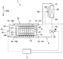
本実施形態の機器温調装置は、電気自動車やハイブリッド車などの電動車両(以下、単に「車両」という)に搭載されるものである。図1に示すように、機器温調装置1は、車両に搭載される二次電池2(以下、「組電池2」という)を冷却する冷却装置として機能する。また、機器温調装置1は、組電池2を暖機する暖機装置としても機能する。
(First embodiment)
The device temperature control device of the present embodiment is installed in an electric vehicle (hereinafter, simply referred to as “vehicle”) such as an electric vehicle or a hybrid vehicle. As shown in FIG. 1, the device
まず、機器温調装置1が温度調整を行う対象機器としての組電池2について説明する。
First, the assembled
機器温調装置1を搭載する車両では、組電池2を主要構成部品として含む蓄電装置(言い換えれば、電池パック)に蓄えた電力がインバータなどを介して車両走行用モータに供給される。組電池2は車両走行中などに電力供給等を行うと自己発熱する。組電池2は高温になると、十分な機能を発揮できないだけでなく、劣化が促進されることから、自己発熱が少なくなるように出力および入力を制限する必要がある。このため、組電池2の出力および入力を確保するためには、組電池2を所定の温度以下に維持するための冷却装置が必要となる。
In a vehicle equipped with the device
また、夏季などの外気温が高い季節では、車両走行中だけでなく、駐車放置中などにも電池温度は上昇する。また、組電池2は車両の床下やトランクルーム下などに配置されることが多く、組電池2に与えられる単位時間当たりの熱量は小さいものの、長時間の放置により電池温度は徐々に上昇する。組電池2を高温状態で放置すると組電池2の寿命が短くなるので、車両の駐車中等にも組電池2の温度を所定の温度以下に維持することが望まれている。
In addition, in a high outside temperature such as summer, the battery temperature rises not only while the vehicle is running but also when the vehicle is left parked. In addition, the assembled
さらに、組電池2は、複数の電池セル21により構成されている。組電池2は、各電池セル21の温度にばらつきがあると電池セル21の劣化に偏りが生じ、蓄電性能が低下してしまう。これは、組電池2が電池セル21の直列接続体を含んでいることで、最も劣化した電池セル21の特性に合わせて組電池2の入出力特性が決まるからである。そのため、長期間にわたって組電池2に所望の性能を発揮させるためには、複数の電池セル21相互間の温度ばらつきを低減させる均温化が重要となる。
Furthermore, the assembled
また、一般に、組電池2を冷却する他の冷却装置として、送風機による空冷式の冷却手段、蒸気圧縮式の冷凍サイクルの冷熱を利用した冷却手段が一般的である。しかし、送風機による空冷式の冷却手段は、車室内の空気を送風するだけなので、冷却能力は低い。また、送風機による送風は、空気の顕熱で組電池2を冷却するので、空気流れの上流と下流との間で温度差が大きくなり、複数の電池セル21同士の温度ばらつきを十分に抑制できない。また、冷凍サイクルの冷熱を利用した冷却手段は、冷却能力は高いものの、車両の駐車中に、電力消費量の多いコンプレッサ等を駆動させることが必要となる。このことは、電力消費量の増大、騒音の増大等を招くことになるため好ましくない。
In addition, as another cooling device for cooling the assembled
そこで、本実施形態の機器温調装置1は、作動流体をコンプレッサにより強制循環させることなく、作動流体の自然循環によって組電池2の温度を調整するサーモサイフォン方式を採用している。
Therefore, the device
次に、機器温調装置1の構成について説明する。
Next, the configuration of the device
図1に示すように、機器温調装置1は、作動流体が循環する流体循環回路4と、その流体循環回路4の動作を制御する制御装置5を備えている。
As shown in FIG. 1, the equipment
流体循環回路4は、作動流体の蒸発および凝縮により熱移動を行うヒートパイプであり、詳細には、気相の作動流体が流れる流路と液相の作動流体が流れる流路とが分離されたループ型のサーモサイフォンである。流体循環回路4は、機器用熱交換器10、凝縮器30、液相通路40、気相通路50および流体通路60などが互いに接続され、閉じられた流体回路として構成されている。また、流体通路60には、作動流体を加熱するための加熱部61が設けられている。
The
流体循環回路4には、その内部が真空排気された状態で、所定量の作動流体が封入されている。作動流体として、例えば、蒸気圧縮式の冷凍サイクルで利用されるHFO−1234yfまたはHFC−134aなどのフロン系冷媒が採用される。なお、図1の矢印DGは、流体循環回路4が車両に搭載された状態における重力方向を示している。
The
流体循環回路4の作動流体の充填量は、後述する暖機時に、機器用熱交換器10の高さ方向の中央付近に液面が形成されるように調整されている。図1では、暖機時の液面の高さの一例を、一点鎖線FLで示している。
The amount of working fluid filled in the
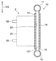
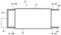
図2〜図4に示すように、機器用熱交換器10は、筒状の上タンク11と、筒状の下タンク12と、その上タンク11と下タンク12とを連通する流路を有する複数のチューブ131により構成されている。なお、複数のチューブ131に代えて、板状の部材の内側に複数の流路を形成したものにより、上タンク11と下タンク12とを接続してもよい。機器用熱交換器10の各構成部材は、例えばアルミニウム、銅等の熱伝導性の高い金属から形成されている。なお、機器用熱交換器10の各構成部材は、金属以外の熱伝導性の高い材料により構成することも可能である。機器用熱交換器10のうち、複数のチューブ131または板状の部材により構成された部位を、熱交換部13ということとする。
As shown in FIGS. 2 to 4, the
上タンク11は、機器用熱交換器10のうち重力方向上側となる位置に設けられる。下タンク12は、機器用熱交換器10のうち重力方向下側となる位置に設けられる。
The
熱交換部13の外側には、電気絶縁性の熱伝導シート14を介して、組電池2が設置される。熱伝導シート14により、熱交換部13と組電池2との間の絶縁が保障されると共に、熱交換部13と組電池2との間の熱抵抗が小さいものとなる。本実施形態では、組電池2は、端子22が設けられた面25とは反対側の面23が、熱伝導シート14を介して、熱交換部13に設置されている。組電池2を構成する複数の電池セル21は、重力方向に交差する方向に並べられている。これにより、複数の電池セル21は、機器用熱交換器10の内側の作動流体との熱交換により、均等に冷却および加熱される。
The assembled
なお、後述する第15〜第18実施形態で説明するように、組電池2の設置方法は、図1〜図3に示したものに限らず、組電池2の他の面が熱伝導シート14を介して熱交換部13に設置されていてもよい。なお、組電池2を構成する各電池セル21の個数、形状なども、図1〜図3に示したものに限らず、任意のものを採用することができる。
As will be described in the fifteenth to eighteenth embodiments described below, the method of installing the assembled
機器用熱交換器10には、上接続部15と下接続部16が設けられている。上接続部15と下接続部16はいずれも、機器用熱交換器10に作動流体を流入させ、または、機器用熱交換器10から作動流体を流出させるための配管接続部である。
The
上接続部15は、機器用熱交換器10のうち重力方向上側の部位に設けられる。本実施形態では、上接続部15は、上タンク11の両側に設けられている。以下の説明では、上タンク11の一端に設けられた上接続部15を第1上接続部151と呼び、上タンク11の他端に設けられた上接続部15を第2上接続部152と呼ぶ。
The
一方、下接続部16は、機器用熱交換器10のうち重力方向下側の部位に設けられる。本実施形態では、下接続部16は、下タンク12の両側に設けられている。以下の説明では、下タンク12の一端に設けられた下接続部16を第1下接続部161と呼び、下タンク12の他端に設けられた下接続部16を第2下接続部162と呼ぶ。
On the other hand, the
第1上接続部151には、気相通路50が接続されている。気相通路50は、凝縮器30の流入口31と、機器用熱交換器10の第1上接続部151とを連通する通路である。一方、第1下接続部161には、液相通路40が接続されている。液相通路40は、凝縮器30の流出口32と、機器用熱交換器10の第1上接続部151とを連通する通路である。なお、気相通路50と液相通路40は、便宜上の呼び名であり、気相または液相の作動流体のみが流れる通路という意味ではない。すなわち、気相通路50と液相通路40のいずれにも、気相と液相の両方の作動流体が流れることがある。また、気相通路50と液相通路40の形状等は、車両への搭載性を考慮して適宜変更可能である。
The
凝縮器30は、機器用熱交換器10より重力方向上側に配置される。凝縮器30のうち上側の部位に流入口31が設けられ、凝縮器30のうち下側の部位に流出口32が設けられている。凝縮器30は、気相通路50を通って流入口31から凝縮器30の内側に流入した気相の作動流体と、所定の受熱流体とを熱交換させるための熱交換器である。本実施形態の凝縮器30は、送風ファン33から送風された空気と気相の作動流体とを熱交換させる空冷式の熱交換器である。すなわち、本実施形態では、所定の受熱流体は空気である。なお、後述する実施形態で説明するように、受熱流体は空気に限るものではなく、例えば冷凍サイクルを循環する冷媒、または、冷却水回路を循環する冷却水など、種々の流体を採用することが可能である。
The
送風ファン33は、車室外の空気または車室内の空気を凝縮器30に向けて流すことが可能である。送風ファン33は、制御装置5からの制御信号に基づいて送風能力が制御される。気相の作動流体は、凝縮器30を通過する空気に放熱することで凝縮する。液相となった作動流体は、自重によって、流出口32から液相通路40を流下し、機器用熱交換器10に流入する。
The
液相通路40の途中には、液相通路40を流れる作動流体の流れを遮断することの可能な流体制御弁70が設けられている。本実施形態の流体制御弁70は、電磁弁であり、制御装置5から伝送される制御信号により、流路断面積が調整される。流体制御弁70が液相通路40を流れる作動流体の流れを遮断すると、流体制御弁70より重力方向上側の液相通路40から凝縮器30に亘って液相の作動流体が貯まり、それ以降、凝縮器30による作動流体の放熱が抑制されるか、または略停止される。したがって、流体制御弁70は、凝縮器30による作動流体の放熱を抑制可能な放熱抑制部として機能するものである。
A
第2上接続部152と第2下接続部162には、流体通路60が接続されている。流体通路60は、その経路上に凝縮器30を含むことなく、機器用熱交換器10の上接続部15と下接続部16とを接続する通路であるので、バイパス通路とも呼ばれる。後述する第20実施形態で説明するように、流体通路60は、第2上接続部152と第2下接続部162とを接続するものに限定されず、気相通路50の途中と液相通路40の途中とを接続してもよい。
The
流体通路60には、流体通路60を流れる液相の作動流体を加熱することの可能な加熱部61が設けられている。本実施形態の加熱部61は、通電により発熱する電気ヒータで構成されている。加熱部61への通電のオンオフは、制御装置5からの制御信号に応じて制御される。加熱部61は、流体通路60が上下方向に延びている部位に設けられている。これにより、加熱部61が流体通路60の作動流体を加熱すると、蒸気となった作動流体は、流体通路60を重力方向上側に流れ、第2上接続部152から機器用熱交換器10に流入する。
The
制御装置5は、プロセッサ、メモリ(例えば、ROM、RAM)を含むマイクロコンピュータと、その周辺回路から構成されている。なお、制御装置5のメモリは、非遷移的実体的記憶媒体で構成されている。制御装置5は、上述した流体循環回路4が備える加熱部61、送風ファン33、および流体制御弁70などの各機器の作動を制御する。
The
続いて、機器温調装置1の作動について説明する。
Next, the operation of the device
図5および図6に示すように、組電池2は、所定の最適温度範囲よりも低温になると、内部抵抗が増加し、出力特性と入力特性が共に低下する。また、組電池2は、所定の最適温度範囲よりも高温になると、出力特性と入力特性が共に低下すると共に、劣化や破損に至るおそれがある。そのため、組電池2に所望の性能を発揮させるためには、組電池2が所定の最適温度範囲よりも低温となるときに組電池2を暖機し、組電池2が所定の最適温度範囲よりも高温となるときに組電池2を冷却することが必要である。
As shown in FIGS. 5 and 6, when the assembled
<冷却時の作動>
図7では、機器温調装置1が組電池2を冷却するときの作動流体の流れを実線および破線の矢印で示している。組電池2の冷却時、制御装置5は、加熱部61への通電をオフし、加熱部61の作動を停止させる。また、制御装置5は、流体制御弁70を開弁し、液相通路40に作動流体が流れるようにする。さらに、制御装置5は、車両が停車中の時には、凝縮器30に送風する送風ファン33の電源をオンする。ただし、制御装置5は、車両が走行中の時には、走行風が凝縮器30に流れるため、送風ファン33の電源をオフする。
<Operation during cooling>
In FIG. 7, the flow of the working fluid when the device
これにより、凝縮器30で凝縮した液相の作動流体は、自重により液相通路40を流れ、第1下接続部161から機器用熱交換器10の下タンク12に流入する。下タンク12に流入した作動流体は、熱交換部13を構成する複数のチューブ131に分流し、組電池2を構成する各電池セル21と熱交換することにより蒸発する。この過程で電池セル21は、作動流体の蒸発潜熱により冷却される。その後、気相となった作動流体は機器用熱交換器10の上タンク11で合流し、第1上接続部151から気相通路50を通り、凝縮器30に流れる。
As a result, the liquid-phase working fluid condensed in the
上述の通り、組電池2の冷却時の作動流体の流れは、凝縮器30→液相通路40→下タンク12→熱交換部13→上タンク11→気相通路50→凝縮器30の順となる。すなわち、機器用熱交換器10と凝縮器30を通るループ状の流路が形成される。
As described above, the flow of the working fluid during cooling of the
なお、組電池2の冷却時に、作動流体の一部は流体通路60にも供給されるが、加熱部61への通電をオフしていることから、流体通路60では作動流体が気化しないため、流体通路60に作動流体の流れは殆ど生じない。
Note that when the assembled
<暖機時の作動>
図8では、機器温調装置1が組電池2を暖機するときの作動流体の流れを実線および破線の矢印で示している。組電池2の暖機時、制御装置5は、加熱部61への通電をオンし、加熱部61を作動させる。また、制御装置5は、流体制御弁70を閉弁し、液相通路40の作動流体の流れを遮断する。
<Operation during warm-up>
In FIG. 8, the flow of the working fluid when the device
加熱部61が作動することにより、流体通路60の作動流体が気化し、蒸気となった作動流体は、流体通路60を重力方向上側に流れ、第2上接続部152から機器用熱交換器10の上タンク11に流入する。気相の作動流体は、温度が低い方へ流れる性質から、低温の電池セル21が接触している複数のチューブ131に分流し、低温の各電池セル21と熱交換することにより凝縮する。この過程で電池セル21は、作動流体の凝縮潜熱により暖機(すなわち加熱)される。その後、液相となった作動流体は機器用熱交換器10の下タンク12で合流し、第2下接続部162から流体通路60に流れる。上述の通り、組電池2の暖機時の作動流体の流れは、流体通路60→上タンク11→熱交換部13→下タンク12→流体通路60の順となる。すなわち、凝縮器30を通ることなく、機器用熱交換器10と流体通路60を通るループ状の流路が形成される。
When the
なお、組電池2の暖機時に、気相の作動流体の一部は気相通路50と凝縮器30にも供給されるが、流体制御弁70を閉弁しているので、流体制御弁70より重力方向上側の液相通路40から凝縮器30に亘り液相の作動流体が貯まる。これにより、凝縮器30による作動流体の放熱が抑制または略停止され、気相通路50と液相通路40に作動流体の流れは殆ど生じない。
Note that when the assembled
上述したように、暖機時には、流体制御弁70より重力方向上側の液相通路40から凝縮器30に亘り液相の作動流体が貯まった状態となる。この状態で、機器用熱交換器10の熱交換部13の中央部付近に液面FLが形成されるよう、流体循環回路4への作動流体の封入量、および、流体制御弁70の取付位置が調整されている。
As described above, during warming up, the working fluid in the liquid phase is accumulated from the
本実施形態の機器温調装置1は、冷却時と暖機時で、機器用熱交換器10のチューブ131を流れる作動流体の流れを逆方向にするよう切り替え、機器用熱交換器10を流れる作動流体の液相と気相との相変化により組電池2の温度を調整する。その際、機器温調装置1は、冷却時には機器用熱交換器10を蒸発器として使用し、暖機時には機器用熱交換器10を凝縮器30として使用することで、同一の機器用熱交換器10を使用して冷却と暖機を可能としている。
The device
以上説明した本実施形態の機器温調装置1は、次の作用効果を奏する。
The device
(1)本実施形態の機器温調装置1は、組電池2の暖機時に、機器用熱交換器10の外側に設けた流体通路60を流れる作動流体を加熱部61により加熱する構成である。そのため、流体通路60で気化した作動流体の蒸気が機器用熱交換器10に供給されるため、機器用熱交換器10の内側で作動流体の蒸気温度のばらつきが抑制される。したがって、この機器温調装置1は、組電池2を均一に暖機することが可能である。その結果、組電池2の入出力特性の低下を防ぎ、その組電池2の劣化や破損を抑制することができる。
(1) The device
(2)本実施形態の機器温調装置1は、組電池2の冷却時に、凝縮器30→液相通路40→下接続部16→機器用熱交換器10→上接続部15→気相通路50→凝縮器30の順に作動流体が循環する。一方、組電池2の暖機時に、流体通路60→上接続部15→機器用熱交換器10→下接続部16→流体通路60の順に作動流体が循環する。すなわち、この機器温調装置1は、組電池2の冷却時と暖機時のいずれにおいても、作動流体の流れる流路がループ状に形成される。そのため、液相の作動流体と気相の作動流体とが一つの流路を対向して流れることが防がれる。したがって、この機器温調装置1は、作動流体を円滑に循環させることで、組電池2の暖機と冷却を高効率に行うことができる。
(2) When cooling the assembled
(3)本実施形態の機器温調装置1は、機器用熱交換器10の上接続部15と下接続部16とを接続する流体通路60の高さ方向に、加熱部61を設けるための空間が確保されるので、機器用熱交換器10より下側に加熱部61を設ける必要性が低減される。したがって、この機器温調装置1は、車両への搭載性を向上することができる。
(3) The equipment
(4)本実施形態の機器温調装置1は、凝縮器30による作動流体の放熱を抑制可能な放熱抑制部としての流体制御弁70を備えている。これによれば、組電池2の暖機時に流体制御弁70を閉弁することで、流体制御弁70から凝縮器30に液相の作動流体が貯まり、凝縮器30による作動流体の放熱が抑制される。それに伴い、気相通路50、凝縮器30および液相通路40の作動流体の循環が抑制される。そのため、組電池2の暖機時に、流体通路60側のループに作動流体を流すことが可能である。したがって、この機器温調装置1は、作動流体を円滑に循環させることで、組電池2の暖機を高効率に行うことができる。
(4) The device
(5)本実施形態では、加熱部61は、流体通路60のうち、重力方向上下に延びている部位に設けられる。これによれば、加熱部61により加熱されて気化した作動流体は、流体通路60を重力方向上側に速やかに流れる。そのため、気相の作動流体が流体通路60から第2下接続部162側へ逆流することが防がれる。したがって、この機器温調装置1は、作動流体を円滑に循環させることで、組電池2の暖機を高効率に行うことができる。
(5) In the present embodiment, the
(第2実施形態)
第2実施形態について説明する。第2実施形態は、第1実施形態に対して、機器温調装置1の作動流体の冷却するための構成を変更したものであり、その他については第1実施形態と同様であるため、第1実施形態と異なる部分についてのみ説明する。
(Second embodiment)
The second embodiment will be described. The second embodiment is different from the first embodiment in the configuration for cooling the working fluid of the device
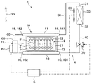
図9に示すように、第2実施形態の機器温調装置1は、冷凍サイクル8を備えている。冷凍サイクル8は、圧縮機81、高圧側熱交換器82、第1流量規制部83、第1膨張弁84、冷媒―作動流体熱交換器85、第2流量規制部86、第2膨張弁87、低圧側熱交換器88、および、それらを接続する冷媒配管89などを有している。冷凍サイクル8に使用する冷媒は、機器温調装置1に用いられる作動流体と同一のものであってもよく、または、異なるものであってもよい。
As shown in FIG. 9, the equipment
圧縮機81は、冷媒―作動流体熱交換器85および低圧側熱交換器88側の冷媒配管89から冷媒を吸引し圧縮する。圧縮機81は、図示していない車両の走行用エンジンまたは電動機等から動力が伝達されて駆動する。
The
圧縮機81から吐出された高圧の気相冷媒は高圧側熱交換器82に流入する。高圧側熱交換器82に流入した高圧の気相冷媒は、高圧側熱交換器82の流路を流れる際、外気との熱交換により放熱して凝縮する。
The high-pressure vapor-phase refrigerant discharged from the
高圧側熱交換器82で凝縮された液相冷媒の一部は、第1流量規制部83を通り、第1膨張弁84を通過する際に減圧され、霧状の気液二相状態となって冷媒―作動流体熱交換器85に流入する。第1流量規制部83は、第1膨張弁84から冷媒―作動流体熱交換器85に流入する冷媒量を調整可能である。冷媒―作動流体熱交換器85に流入した冷媒は、冷媒―作動流体熱交換器85の流路を流れる際、冷媒の蒸発潜熱により、機器温調装置1の流体循環回路4を構成する凝縮器30を流れる作動流体を冷却する。すなわち、本実施形態の機器温調装置1の流体循環回路4の凝縮器30と、冷凍サイクル8の冷媒―作動流体熱交換器85とは一体に構成され、流体循環回路4を流れる作動流体と冷凍サイクル8を流れる冷媒とを熱交換させるものである。冷媒―作動流体熱交換器85を通過した冷媒は、図示していないアキュムレータを経由して圧縮機81に吸引される。
A part of the liquid-phase refrigerant condensed in the high-pressure
一方、高圧側熱交換器82で凝縮された液相冷媒の他の一部は、第2流量規制部86を通り、第2膨張弁87を通過する際に減圧され、霧状の気液二相状態となって低圧側熱交換器88に流入する。第2流量規制部86は、第2膨張弁87から低圧側熱交換器88に流入する冷媒量を調整可能である。低圧側熱交換器88は、例えば車室内の空気調和を行うための空調装置に用いられる。その場合、低圧側熱交換器88に流入した冷媒は、冷媒の蒸発潜熱により、車室内に送風される空気を冷却する。低圧側熱交換器88を通過した冷媒も、図示していないアキュムレータを経由して圧縮機81に吸引される。
On the other hand, the other part of the liquid-phase refrigerant condensed in the high-pressure
以上説明した第2実施形態では、流体循環回路4を構成する凝縮器30と冷凍サイクル8を構成する冷媒―作動流体熱交換器85とが一体に構成され、流体循環回路4を流れる作動流体が冷凍サイクル8を流れる冷媒との熱交換により冷却される構成である。
In the second embodiment described above, the
これによれば、冷凍サイクル8を構成する冷媒―作動流体熱交換器85に流れる冷媒量を第1流量規制部83などにより調整することで、機器温調装置1の凝縮器30を流れる作動流体に供給する冷熱量を調整することが可能である。したがって、第2実施形態では、機器温調装置1による組電池2の冷却能力を、組電池2の発熱量に応じて適切に調整することができる。
According to this, the working fluid flowing through the
なお、上述した冷凍サイクル8は、クーラサイクルだけでなく、ヒートポンプサイクルとしてもよい。また、上述した冷凍サイクル8は、車室内の空気調和を行うための空調装置とは切り離された、組電池2の冷却に用いるためのスタンドアローンとしてもよい。
The
(第3実施形態)
第3実施形態について説明する。第3実施形態は、第1および第2実施形態に対して、機器温調装置1の作動流体の冷却するための構成を変更したものであり、その他については第1および第2実施形態と同様であるため、第1および第2実施形態と異なる部分についてのみ説明する。
(Third Embodiment)
A third embodiment will be described. The third embodiment is different from the first and second embodiments in the configuration for cooling the working fluid of the device
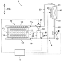
図10に示すように、第3実施形態の機器温調装置1は、冷却水回路9を備えている。冷却水回路9は、ウォータポンプ91、冷却水放熱器92、水―作動流体熱交換器93、および、それらを接続する冷却水配管94を有している。冷却水回路9には、冷却水が流れる。
As shown in FIG. 10, the device
ウォータポンプ91は、冷却水を圧送し、冷却水回路9に冷却水を循環させる。冷却水放熱器92は、その冷却水放熱器92の流路を流れる冷却水を、冷凍サイクル8を構成する蒸発器を流れる冷媒との熱交換により冷却する。すなわち、本実施形態の冷却水回路9の冷却水放熱器92は、冷凍サイクル8の蒸発器と一体に構成されたチラーであり、冷却水回路9を流れる冷却水と冷凍サイクル8を流れる低圧冷媒とを熱交換させるものである。冷却水放熱器92から流出した冷却水は、水―作動流体熱交換器93に流入する。
The
水―作動流体熱交換器93に流入した冷却水は、その水―作動流体熱交換器93の流路を流れる際、機器温調装置1の流体循環回路4を構成する凝縮器30を流れる作動流体を冷却する。すなわち、本実施形態の機器温調装置1の流体循環回路4の凝縮器30と、冷却水回路9の水―作動流体熱交換器93とは一体に構成され、流体循環回路4を流れる作動流体と冷却水回路9を流れる冷却水とを熱交換させるものである。
When the cooling water that has flowed into the water-working fluid heat exchanger 93 flows through the flow path of the water-working fluid heat exchanger 93, the cooling water that flows through the
以上説明した第3実施形態では、流体循環回路4を構成する凝縮器30と冷却水回路9を構成する水―作動流体熱交換器93とが一体に構成され、流体循環回路4を流れる作動流体が冷却水回路9を流れる冷却水との熱交換により冷却される構成である。
In the third embodiment described above, the
これによれば、冷凍サイクル8を流れる低圧冷媒の温度と、冷却水回路9を流れる冷却水の温度を異なる温度に設定することが可能である。そのため、この機器温調装置1は、冷凍サイクル8を流れる低圧冷媒の温度と、冷却水回路9を流れる冷却水の温度をそれぞれ適切に調整することが可能である。したがって、冷却水回路9を流れる冷却水から機器温調装置1の凝縮器30を流れる作動流体に供給する冷熱量を調整し、機器温調装置1による組電池2の冷却能力を、組電池2の発熱量に応じて適切に調整することができる。
According to this, it is possible to set the temperature of the low-pressure refrigerant flowing through the
(第4実施形態)
第4実施形態について説明する。第4実施形態は、第3実施形態に対して、冷却水回路9の構成の一部を変更したものであり、その他については第3実施形態と同様であるため、第3実施形態と異なる部分についてのみ説明する。
(Fourth Embodiment)
A fourth embodiment will be described. In the fourth embodiment, a part of the configuration of the cooling
図11に示すように、第4実施形態の機器温調装置1は、冷却水回路9に空冷放熱器95を備えている。空冷放熱器95は、その空冷放熱器95の流路を流れる冷却水を、外気との熱交換により冷却する。冷却水回路9の中で、空冷放熱器95と冷却水放熱器92とは、並列に接続されている。
As shown in FIG. 11, the device
第4実施形態では、冷却水回路9を流れる冷却水の冷却能力を高めることが可能である。そのため、この機器温調装置1は、組電池2の冷却能力を向上することができる。
In the fourth embodiment, it is possible to enhance the cooling capacity of the cooling water flowing through the cooling
(第5実施形態)
第5実施形態について説明する。第5実施形態は、第1実施形態に対して、流体循環回路4の構成の一部を変更したものであり、その他については第1実施形態と同様であるため、第1実施形態と異なる部分についてのみ説明する。
(Fifth Embodiment)
A fifth embodiment will be described. In the fifth embodiment, a part of the configuration of the
図12および図13に示すように、第5実施形態の機器温調装置1は、液相通路40の途中に流体制御弁70が設けられていない。その代り、第5実施形態では、空冷式の凝縮器30に対し、その凝縮器30を通過する空気の流通を遮断可能な扉部材としてのシャッタ34を設置している。シャッタ34は、制御装置5から伝送される制御信号により、開閉動作が制御される。
As shown in FIGS. 12 and 13, in the device
図12に示すように、シャッタ34が開いた状態となると、凝縮器30を通過する空気の流通が許容される。そのため、送風ファン33による送風空気または走行風が凝縮器30を通過し、凝縮器30による作動流体の放熱が行われる。そのため、組電池2の冷却時に、機器温調装置1の流体循環回路4を作動流体が、凝縮器30→液相通路40→下タンク12→熱交換部13→上タンク11→気相通路50→凝縮器30の順に流れるようにすることができる。
As shown in FIG. 12, when the
一方、図13に示すように、シャッタ34が閉じた状態となると、凝縮器30を通過する空気の流通が遮断される。これにより、凝縮器30による作動流体の放熱が抑制されるか、または略停止される。そのため、組電池2の暖機時に、機器温調装置1の流体循環回路4を作動流体が、流体通路60→上タンク11→熱交換部13→下タンク12→流体通路60の順に流れるようにすることができる。したがって、本実施形態のシャッタ34は、凝縮器30による作動流体の放熱を抑制可能な放熱抑制部として機能するものである。
On the other hand, as shown in FIG. 13, when the
以上説明した第5実施形態では、空冷式の凝縮器30にシャッタ34を設けることで、第1〜第4実施形態において液相通路40の途中に設置した流体制御弁70を廃止することが可能である。
In the fifth embodiment described above, by providing the
(第6実施形態)
第6実施形態について説明する。第6実施形態は、第2実施形態に対して、流体循環回路4の構成の一部を変更したものであり、その他については第2実施形態と同様であるため、第2実施形態と異なる部分についてのみ説明する。
(Sixth Embodiment)
A sixth embodiment will be described. The sixth embodiment is a modification of the second embodiment with a part of the configuration of the
図14に示すように、第6実施形態の機器温調装置1は、液相通路40の途中に流体制御弁70が設けられていない。そのため、第6実施形態では、組電池2の暖機時に、流体制御弁70の制御に代えて、冷凍サイクル8に設置した第1流量規制部83により、第1膨張弁84から冷媒―作動流体熱交換器85に流入する冷媒を遮断する。これにより、凝縮器30による作動流体の放熱が抑制されるか、または略停止される。そのため、組電池2の暖機時に、機器温調装置1の流体循環回路4を作動流体が、流体通路60→上タンク11→熱交換部13→下タンク12→流体通路60の順に流れるようにすることができる。したがって、本実施形態の第1流量規制部83は、凝縮器30による作動流体の放熱を抑制可能な放熱抑制部として機能するものである。
As shown in FIG. 14, the device
なお、第6実施形態では、低圧側熱交換器88を使用していない場合、組電池2の暖機時に、圧縮機81の作動を停止してもよい。
In the sixth embodiment, when the low-pressure
以上説明した第6実施形態では、組電池2の暖機時に、第1流量規制部83を閉状態に制御することにより、第1〜第4実施形態において液相通路40の途中に設置した流体制御弁70を廃止することが可能である。
In the sixth embodiment described above, the fluid installed in the
(第7実施形態)
第7実施形態について説明する。第7実施形態は、第3実施形態に対して、流体循環回路4の構成の一部を変更したものであり、その他については第3実施形態と同様であるため、第3実施形態と異なる部分についてのみ説明する。
(Seventh embodiment)
The seventh embodiment will be described. In the seventh embodiment, a part of the configuration of the
図15に示すように、第7実施形態の機器温調装置1は、液相通路40の途中に流体制御弁70が設けられていない。そのため、第7実施形態では、組電池2の暖機時に、流体制御弁70の制御に代えて、冷却水回路9に設置したウォータポンプ91の駆動を停止し、水―作動流体熱交換器93の冷却水の流れを遮断する。これにより、凝縮器30による作動流体の放熱が抑制されるか、または略停止される。そのため、組電池2の暖機時に、機器温調装置1の流体循環回路4を作動流体が、流体通路60→上タンク11→熱交換部13→下タンク12→流体通路60の順に流れるようにすることができる。したがって、本実施形態のウォータポンプ91は、凝縮器30による作動流体の放熱を抑制可能な放熱抑制部として機能するものである。
As shown in FIG. 15, in the device
以上説明した第7実施形態では、組電池2の暖機時に、ウォータポンプ91の駆動を停止することにより、第1〜第4実施形態において液相通路40の途中に設置した流体制御弁70を廃止することが可能である。
In the seventh embodiment described above, when the assembled
(第8実施形態)
第8実施形態について説明する。第8実施形態は、第1実施形態に対して、流体制御弁70の取付位置を変更したものであり、その他については第1実施形態と同様であるため、第1実施形態と異なる部分についてのみ説明する。
(Eighth Embodiment)
The eighth embodiment will be described. The eighth embodiment differs from the first embodiment in that the mounting position of the
図16に示すように、第8実施形態の機器温調装置1は、気相通路50の途中に流体制御弁70が設けられている。そのため、第8実施形態では、組電池2の暖機時に、流体制御弁70が気相通路50を流れる作動流体の流れを遮断すると、凝縮器30による作動流体の凝縮が停止する。そのため、組電池2の暖機時に、機器温調装置1の流体循環回路4を作動流体が、流体通路60→上タンク11→熱交換部13→下タンク12→流体通路60の順に流れるようにすることができる。
As shown in FIG. 16, the equipment
(第9実施形態)
第9実施形態について説明する。第9実施形態は、第2実施形態に対して、機器温調装置1の流体循環回路4の構成の一部を変更したものであり、その他については第2実施形態と同様であるため、第2実施形態と異なる部分についてのみ説明する。
(9th Embodiment)
The ninth embodiment will be described. In the ninth embodiment, a part of the configuration of the
図17に示すように、第9実施形態の機器温調装置1は、流体循環回路4に2種類の凝縮器30a、30bを備えている。一方の凝縮器30aは、第1実施形態などで説明した空冷式の凝縮器30aである。他方の凝縮器30bは、第2実施形態などで説明した冷凍サイクル8の冷媒―作動流体熱交換器85と一体に構成されたものである。この2種類の凝縮器30a、30bは、並列に接続されている。なお、流体制御弁70は、2種類の凝縮器30a、30bから延びる液相通路40の合流部47と、機器用熱交換器10の第1下接続部161との間に設けられている。
As shown in FIG. 17, the device
第9実施形態の機器温調装置1は、凝縮器30a、30bによる作動流体の凝縮能力を高めることで、組電池2の冷却性能を向上することができる。
The device
なお、機器温調装置1の流体循環回路4に設けられる複数の凝縮器30a、30bの組み合わせは、図17に示したものに限らず、種々の組み合わせを採用することができる。
The combination of the plurality of
(第10実施形態)
第10実施形態について説明する。第10実施形態は、第9実施形態に対して、流体制御弁70の取付位置を変更したものであり、その他については第9実施形態と同様であるため、第9実施形態と異なる部分についてのみ説明する。
(10th Embodiment)
A tenth embodiment will be described. The tenth embodiment differs from the ninth embodiment in that the mounting position of the
図18に示すように、第10実施形態では、空冷式の凝縮器30aと液相通路40の合流部47との間に流体制御弁70が設けられている。
As shown in FIG. 18, in the tenth embodiment, a
空冷式の凝縮器30aでは、シャッタ34が設けていない場合、走行風などにより熱交換が行われることとなる。しかし、空冷式の凝縮器30aに対してシャッタ34を設ける場合、凝縮器30の周りに大きなスペースが必要となり、車両への搭載性が悪化する場合が考えられる。そこで、第10実施形態では、空冷式の凝縮器30aと液相通路40の合流部47との間に流体制御弁70を設けることで、機器温調装置1の体格を小型化し、車両への搭載性を向上することができる。
In the air-cooled
一方、冷凍サイクル8の冷媒―作動流体熱交換器85と一体に構成された凝縮器30bは、冷凍サイクル8に設置した第1流量規制部83を閉じることで、作動流体の放熱を抑制または略停止することが可能である。したがって、第10実施形態においても、組電池2の暖機時に、流体制御弁70と第1流量規制部83を制御することで、作動流体が、流体通路60→上タンク11→熱交換部13→下タンク12→流体通路60の順に流れるようにすることができる。
On the other hand, the
なお、第10実施形態においても、第1実施形態と同様、組電池2の暖機時に、流体制御弁70より重力方向上側の液相通路40から上側に液相の作動流体が貯まる。この状態で、機器用熱交換器10の熱交換部13の中央部付近に液面FLが形成されるよう、流体循環回路4への作動流体の封入量、および、流体制御弁70の取付位置が調整されている。
In the tenth embodiment, as in the first embodiment, when the
(第11実施形態)
第11実施形態について説明する。第11実施形態は、第9実施形態に対して、2種類の凝縮器30の接続方法を変更したものであり、その他については第9実施形態と同様であるため、第9実施形態と異なる部分についてのみ説明する。
(Eleventh embodiment)
An eleventh embodiment will be described. The eleventh embodiment differs from the ninth embodiment in that the connection method of the two types of
図19に示すように、第11実施形態の機器温調装置1は、流体循環回路4に2種類の凝縮器30a、30bを備えている。一方の凝縮器30aは、空冷式の凝縮器30である。他方の凝縮器30bは、冷凍サイクル8の冷媒―作動流体熱交換器85と一体に構成されたものである。この2種類の凝縮器30a、30bは、直列に接続されている。
As shown in FIG. 19, the equipment
なお、機器温調装置1の流体循環回路4に設けられる複数の凝縮器30a、30bの数は、図19などに示したものに限らず、3個以上としてもよい。また、複数の凝縮器30a、30bの接続方法も、図19などに示したものに限らず、並列と直列とを組み合わせてもよい。
The number of the plurality of
第11実施形態の機器温調装置1は、凝縮器30による作動流体の凝縮能力を高めることで、組電池2の冷却性能を向上することができる。
The equipment
(第12実施形態)
第12実施形態について説明する。第12実施形態は、第1実施形態に対して、流体通路60と加熱部61の構成を変更したものであり、その他については第1実施形態と同様であるため、第1実施形態と異なる部分についてのみ説明する。
(Twelfth Embodiment)
A twelfth embodiment will be described. The twelfth embodiment is different from the first embodiment in the configuration of the
図20に示すように、第12実施形態では、流体通路60が略水平方向に延びている部位に加熱部61が設けられている。この場合、仮に、加熱部61により加熱されて蒸気となった作動流体が流体通路60を第2下接続部162側へ逆流すると、作動流体の循環が悪化することが考えられる。
As shown in FIG. 20, in the twelfth embodiment, the
そこで、第12実施形態では、流体通路60は、機器用熱交換器10の第2下接続部162と加熱部61との間に、加熱部61より重力方向下側に延びる逆流抑制部62を有している。具体的には、第12実施形態では、流体通路60の一部がU字状に形成されている。流体通路60のU字状の部位のうち、そのU字状の中央から加熱部61側の部分が逆流抑制部62に相当している。
Therefore, in the twelfth embodiment, the
逆流抑制部62は、加熱部61より重力方向下側に延びていることで、加熱部61により加熱されて気化した作動流体が第2下接続部162側へ逆流することを防ぐことが可能である。したがって、この機器温調装置1は、組電池2の暖機時に、流体通路60→上タンク11→熱交換部13→下タンク12→流体通路60の順に、作動流体を円滑に循環させることができる。
The
(第13実施形態)
第13実施形態について説明する。第13実施形態は、第1実施形態に対して、複数の機器用熱交換器10を備えたものであり、その他については第1実施形態と同様であるため、第1実施形態と異なる部分についてのみ説明する。
(13th Embodiment)
The thirteenth embodiment will be described. The thirteenth embodiment is different from the first embodiment in that a plurality of
図21に示すように、第13実施形態の機器温調装置1は、複数の機器用熱交換器10a、10bを備えている。気相通路50は、一方の機器用熱交換器10aの第1上接続部151aと他方の機器用熱交換器10bの第1上接続部151bとを接続する第1気相通路部51と、その第1気相通路部51の途中から上方に延びて凝縮器30の流入口31に接続される第2気相通路部52とを有している。また、液相通路40は、一方の機器用熱交換器10aの第1下接続部161aと他方の機器用熱交換器10bの第1下接続部161bとを接続する第1液相通路部41と、その第1液相通路部41の途中から上方に延びて凝縮器30の流出口32に接続される第2液相通路部42とを有している。
As shown in FIG. 21, the equipment
一方の機器用熱交換器10aの第2上接続部152aと第2下接続部162aとを流体通路60aが接続し、その流体通路60aに加熱部61aが設けられている。また、他方の機器用熱交換器10bの第2上接続部152bと第2下接続部162bとを別の流体通路60bが接続し、その別の流体通路60bにも別の加熱部61bが設けられている。
The fluid passage 60a connects the second upper connecting portion 152a and the second lower connecting portion 162a of the one
この構成により、第13実施形態の機器温調装置1は、車両の複数個所に組電池2が配置されている場合でも、その組電池2の場所に応じて複数の機器用熱交換器10を配置することができる。
With this configuration, the device
(第14実施形態)
第14実施形態について説明する。第14実施形態も、第1実施形態に対して、複数の機器用熱交換器10を備えたものであり、その他については第1実施形態と同様であるため、第1実施形態と異なる部分についてのみ説明する。
(14th Embodiment)
A fourteenth embodiment will be described. The fourteenth embodiment also includes a plurality of
図22に示すように、第14実施形態の機器温調装置1も、複数の機器用熱交換器10a、10bを備えている。気相通路50は、一方の機器用熱交換器10aの第1上接続部151aと他方の機器用熱交換器10bの第2上接続部152bとを接続する熱交換器用気相通路53と、他方の機器用熱交換器10bの第1上接続部151bと凝縮器30の流入口31とを接続する凝縮器用気相通路54とを有している。また、液相通路40は、一方の機器用熱交換器10aの第1下接続部161aと他方の機器用熱交換器10bの第2下接続部162bとを接続する熱交換器用液相通路43と、他方の機器用熱交換器10bの第1下接続部161bと凝縮器30の流出口32とを接続する凝縮器用液相通路44とを有している。
As shown in FIG. 22, the equipment
一方の機器用熱交換器10aの第2上接続部152aと第2下接続部162aとを流体通路60aが接続し、その流体通路60aに加熱部61aが設けられている。
The fluid passage 60a connects the second upper connecting portion 152a and the second lower connecting portion 162a of the one
この構成によっても、第14実施形態の機器温調装置1は、車両の複数個所に組電池2が配置されている場合でも、その組電池2の場所に応じて複数の機器用熱交換器10を配置することができる。
With this configuration as well, the device
(第15実施形態)
第15実施形態について説明する。以下に説明する第15および第16実施形態は、上述した第1〜第14実施形態に対して、機器用熱交換器10に対する組電池2の設置方法を変更したものであり、その他については第1〜第14実施形態と同様であるため、第1〜第14実施形態と異なる部分についてのみ説明する。
(15th Embodiment)
A fifteenth embodiment will be described. Fifteenth and sixteenth embodiments described below are different from the above-described first to fourteenth embodiments in that the installation method of the assembled
図23に示すように、第15実施形態では、組電池2は、その組電池2を構成する各電池セル21の端子22が重力方向上側となるように設置されている。組電池2は、端子22が設けられた面25に対して垂直な面24が、機器用熱交換器10の熱交換部13の側面に、熱伝導シート14を介して設置されている。
As shown in FIG. 23, in the fifteenth embodiment, the assembled
(第16実施形態)
図24に示すように、第16実施形態では、組電池2は、その組電池2を構成する各電池セル21の端子22が重力方向に対して交差する向きとなるように設置されている。組電池2は、端子22が設けられた面25とは反対側の面23が、機器用熱交換器10の熱交換部13の側面に、熱伝導シート14を介して設置されている。なお、組電池2は、熱交換部13の一方の側面にのみ設置されており、他方の側面には設置されていない。
(16th Embodiment)
As shown in FIG. 24, in the sixteenth embodiment, the
(第17実施形態)
第17実施形態について説明する。以下に説明する第17および第18実施形態は、上述した第1〜第14実施形態に対して、機器用熱交換器10の構成と、それに対する組電池2の設置方法を変更したものであり、その他については第1〜第14実施形態と同様であるため、第1〜第14実施形態と異なる部分についてのみ説明する。
(17th Embodiment)
A seventeenth embodiment will be described. The seventeenth and eighteenth embodiments described below are different from the above-described first to fourteenth embodiments in that the configuration of the
図25に示すように、第17実施形態では、機器用熱交換器10は、2本の下タンク121、122と、1本の上タンク11とを有している。また、この機器用熱交換器10は、2本の下タンク121、122同士を接続する水平熱交換部132と、その水平熱交換部132に対し垂直に設けられた垂直熱交換部133とを有している。垂直熱交換部133のうち重力方向下側の部位は水平熱交換部132の中間位置に接続されており、垂直熱交換部133のうち重力方向下側の部位は上タンク11に接続されている。なお、2本の下タンク121、122、1本の上タンク11、水平熱交換部132および垂直熱交換部133は一体に形成されている。
As shown in FIG. 25, in the seventeenth embodiment, the
組電池2は、その組電池2を構成する各電池セル21の端子22が重力方向に対して交差する向きとなるように設置されている。組電池2は、端子22が設けられた面25に対して垂直な面24が、熱伝導シート14を介して、水平熱交換部132に設置されている。また、組電池2は、端子22が設けられた面25とは反対側の面23が、熱伝導シート14を介して、垂直熱交換部133に設置されている。
The assembled
第17実施形態では、機器用熱交換器10は、組電池2の端子22が設けられた面25に対して垂直な面24と、端子22が設けられた面25とは反対側の面23を、同時に冷却または暖機することができる。
In the seventeenth embodiment, the
(第18実施形態)
図26に示すように、第18実施形態では、機器用熱交換器10の熱交換部13は、水平方向に延びる水平部134と、その水平部134の一方の部位から重力方向斜め下に延びる第1傾斜部135と、水平部134の他方の部位から重力方向斜め上に延びる第2傾斜部136とを有している。第1傾斜部135のうち水平部134とは反対側の部位に下タンク12が接続されている。第2傾斜部136のうち水平部134とは反対側の部位に上タンク11が接続されている。すなわち、上タンク11は、下タンク12より高い位置に配置されている。水平部134、第1傾斜部135、第2傾斜部136、下タンク12および上タンク11は一体に形成されている。
(Eighteenth embodiment)
As shown in FIG. 26, in the eighteenth embodiment, the
組電池2は、その組電池2を構成する各電池セル21の端子22が重力方向上向きとなるように設置されている。組電池2は、端子22が設けられた面25とは反対側の面23が、熱伝導シート14を介して、熱交換部13の水平部134に設置されている。
The assembled
なお、組電池2の設置方法は、第1〜第18実施形態で示したものに限らず、種々の設置方法を採用することが可能である。なお、組電池2を構成する各電池セル21の個数、形状なども、第1〜第18実施形態で示したものに限らず、任意のものを採用することが可能である。
The installation method of the assembled
(第19実施形態)
第19実施形態について説明する。第19実施形態は、第1実施形態に対して、流体通路60の構成の一部を変更したものであり、その他については第1実施形態と同様であるため、第1実施形態と異なる部分についてのみ説明する。
(19th Embodiment)
A nineteenth embodiment will be described. In the nineteenth embodiment, a part of the configuration of the
図27および図28に示すように、第19実施形態では、流体通路60は、経路の途中に、流体通路60を流れる液相の作動流体を貯める貯液部63を有している。貯液部63は、少なくとも一部が、機器用熱交換器10の上接続部15と下接続部16との高さ範囲内に位置している。これにより、機器温調装置1は、組電池2の冷却および暖機に必要な作動流体の量を貯液部63に貯め、その貯液部63の液面FLの高さを調整することで、組電池2の加熱時と冷却時で、機器用熱交換器10の作動流体の液面FLの高さを容易に調整することができる。
As shown in FIGS. 27 and 28, in the nineteenth embodiment, the
図28は、機器用熱交換器10と流体通路60の断面図である。貯液部63は、流体通路60の経路のうち一部の内径を大きくすることで形成されている。これにより、流体通路60に対し、貯液部63を簡素な構成で設けることができる。
FIG. 28 is a cross-sectional view of the
また、加熱部61は、貯液部63に貯められた液相の作動流体を加熱可能な位置に設けられている。これにより、加熱部61による作動流体の加熱効率を高めることができる。
The
(第20実施形態)
第20実施形態について説明する。第20実施形態は、第1実施形態に対して、流体通路60の構成等を変更したものであり、その他については第1実施形態と同様であるため、第1実施形態と異なる部分についてのみ説明する。
(Twentieth Embodiment)
A twentieth embodiment will be described. The twentieth embodiment is different from the first embodiment in the configuration of the
図29および図30に示すように、第20実施形態では、流体通路60は、貯液部63を有している。流体通路60が有する貯液部63は、液相通路40に連通している。また、流体通路60のうち、貯液部63とは反対側の部位は、三方切替弁71を介して気相通路50に連通している。
As shown in FIGS. 29 and 30, in the twentieth embodiment, the
図29では、機器温調装置1が組電池2を冷却するときの作動流体の流れを実線および破線の矢印で示している。第1実施形態で説明したように、組電池2の冷却時、制御装置5は、加熱部61への通電をオフし、加熱部61の作動を停止させる。また、制御装置5は、流体制御弁70を開弁し、液相通路40に作動流体が流れるようにする。さらに、制御装置5は、車両が停車中の時には、凝縮器30に送風する送風ファン33の電源をオンする。ただし、制御装置5は、車両が走行中の時には、走行風が凝縮器30に流れるため、送風ファン33の電源をオフする。
In FIG. 29, the flow of the working fluid when the
さらに、第20実施形態では、組電池2の冷却時、制御装置5は、三方切替弁71を制御する。三方切替弁71の動作により、三方切替弁71よりも上接続部15側の気相通路50と、三方切替弁71よりも凝縮器30側の気相通路50とが連通すると共に、流体通路60と気相通路50との連通が遮断される。
Furthermore, in the twentieth embodiment, the
これにより、組電池2の冷却時の作動流体の流れは、凝縮器30→液相通路40→下タンク12→熱交換部13→上タンク11→気相通路50→凝縮器30の順となる。すなわち、機器用熱交換器10と凝縮器30を通るループ状の流路が形成される。
Accordingly, the flow of the working fluid when the assembled
これに対し、図30では、機器温調装置1が組電池2を暖機するときの作動流体の流れを実線および破線の矢印で示している。第1実施形態で説明したように、組電池2の暖機時、制御装置5は、加熱部61への通電をオンし、加熱部61を作動させる。また、制御装置5は、流体制御弁70を閉弁し、液相通路40の作動流体の流れを遮断する。
On the other hand, in FIG. 30, the flow of the working fluid when the device
さらに、第20実施形態では、組電池2の暖機時、制御装置5は、三方切替弁71を制御する。三方切替弁71の動作により、三方切替弁71よりも上接続側の気相通路50と流体通路60とが連通すると共に、三方切替弁71よりも凝縮器30側の気相通路50と流体通路60との連通が遮断される。
Furthermore, in the twentieth embodiment, when the
これにより、組電池2の暖機時の作動流体の流れは、流体通路60→上タンク11→熱交換部13→下タンク12→流体通路60の順となる。すなわち、凝縮器30を通ることなく、機器用熱交換器10と流体通路60を通るループ状の流路が形成される。
As a result, the flow of the working fluid when the assembled
(第21実施形態)
第21実施形態について説明する。第21実施形態は、第1〜第20実施形態に対して、機器用熱交換器10の構成を変更したものであり、その他については第1〜第20実施形態と同様であるため、第1〜第20実施形態と異なる部分についてのみ説明する。
(Twenty-first embodiment)
The twenty-first embodiment will be described. The twenty-first embodiment differs from the first to twentieth embodiments in that the configuration of the
図31に示すように、第21実施形態の機器用熱交換器10は、上タンク、下タンクおよび複数のチューブを有していない。第21実施形態の機器用熱交換器10は、単一の容器17により構成されている。このような第21実施形態の機器用熱交換器10でも、第1〜第20実施形態で説明した機器用熱交換器10と同様の作用効果を奏することができる。
As shown in FIG. 31, the
(第22実施形態)
第22実施形態について説明する。第22実施形態は、第1実施形態に対して、機器温調装置1の冷却機能を除いたものであり、その他については第1実施形態と同様であるため、第1実施形態と異なる部分についてのみ説明する。
(22nd Embodiment)
A twenty-second embodiment will be described. The 22nd embodiment is the same as the first embodiment except that the cooling function of the device
図32に示すように、第22実施形態の機器用熱交換器10は、凝縮器30、液相通路40、気相通路50を備えていない。第22実施形態の機器用熱交換器10が備える流体循環回路4は、機器用熱交換器10と流体通路60とが閉じられた流体回路として構成されている。
As shown in FIG. 32, the
流体通路60は、一端が機器用熱交換器10の上接続部15に接続され、他端が機器用熱交換器10の下接続部16に接続されている。流体通路60には、流体通路60を流れる液相の作動流体を加熱するための加熱部61が設けられている。
The
組電池2の暖機時、制御装置5は、加熱部61への通電をオンし、加熱部61を作動させる。加熱部61により加熱されて蒸気となった作動流体は、流体通路60を重力方向上側に流れ、上接続部15から機器用熱交換器10の上タンク11に流入する。気相の作動流体は、温度が低い方へ流れる性質から、低温の電池セル21が接触している複数のチューブ131に分流し、低温の各電池セル21と熱交換することにより凝縮する。この過程で電池セル21は、作動流体の凝縮潜熱により暖機(すなわち加熱)される。その後、液相となった作動流体は機器用熱交換器10の下タンク12で合流し、下接続部16から流体通路60に流れる。上述の通り、組電池2の暖機時の作動流体の流れは、流体通路60→上タンク11→熱交換部13→下タンク12→流体通路60の順となる。すなわち、機器用熱交換器10と流体通路60を通るループ状の流路が形成される。
When the assembled
第22実施形態の機器温調装置1は、上述した第1実施形態で説明した機器温調装置1の暖機時の作用効果と、同様の作用効果を奏することが可能である。また、第22実施形態の構成に対し、上述した第1〜第21実施形態で説明した構成を適宜組み合わせることも可能である。
The equipment
(第23実施形態)
第23実施形態について図33〜図39を参照して説明する。上述の第1〜第22実施形態で説明したように、機器温調装置1が対象機器としての組電池2の暖機を行う際、加熱部61により加熱されて気相となった作動流体は、流体通路60から上接続部15を経由して機器用熱交換器10に流入する。その気相の作動流体は、機器用熱交換器10内で低温の各電池セル21に放熱して凝縮し、液相となる。その際、機器用熱交換器10内では、複数のチューブ131内の上方部分で作動流体の凝縮量が多く、複数のチューブ131内の下方部分では液相の作動流体が底部および側壁に溜まることから作動流体の凝縮量が少ない。そのため、各電池セル21の上方部分は作動流体の凝縮潜熱による加熱量が大きいが、各電池セル21の下方部分は上方部分に比べて加熱量が小さい。その結果、電池セル21の上方部分と下方部分とで温度のばらつき(すなわち温度分布)が大きくなると、組電池2が充放電を行う際に、電池セル21の温度の高い上方部分に電流集中が発生することが懸念される。
(23rd Embodiment)
The twenty-third embodiment will be described with reference to FIGS. 33 to 39. As described in the above-described first to twenty-second embodiments, when the device
そこで、以下に説明する第23実施形態から第26実施形態は、機器温調装置1が組電池2の暖機を行う際に、組電池2の温度分布を抑制することを目的としている。
Therefore, the 23rd to 26th embodiments described below are intended to suppress the temperature distribution of the assembled
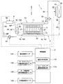
図33に示すように、本実施形態の機器温調装置1の構成は、第8実施形態で説明した構成と同じである。すなわち、加熱部61は、通電により発熱する電気ヒータで構成されている。
As shown in FIG. 33, the configuration of the device
なお、図33では、制御装置5に接続される各センサおよび制御装置5の構成が例示されている。制御装置5には、電池の温度を検出する1個または複数の電池温度センサ101、サーモサイフォン回路を循環する作動流体の温度を検出する作動流体温度センサ102、および、加熱部61の温度を検出するヒータ温度センサ103などから伝送される信号が入力される。また、制御装置5は、組電池2の温度分布の大きさを判定する温度分布判定部110、加熱部61への通電時間を検出するヒータ通電時間検出部111、加熱部61へ供給される電力を検出するヒータ電力検出部112などを有している。なお、制御装置5、温度分布判定部110、ヒータ通電時間検出部111、ヒータ電力検出部112などは、一体に構成されていてもよく、それぞれが別々に構成されていてもよい。このことは、後述する実施形態でも同じである。
Note that FIG. 33 illustrates the configuration of each sensor connected to the
図33および図35は、機器温調装置1が組電池2の暖機を行う前の状態を示している。制御装置5は、加熱部61への通電を停止している。この状態で、図35に示すように、機器用熱交換器10内の作動流体の液面FLは、電池セル21の高さ方向で比較的低い位置にある。
33 and 35 show a state before the device
次に、図34および図36は、機器温調装置1が組電池2の暖機を行っているときの状態を示している。組電池2の暖機時、制御装置5は、加熱部61への通電を行い、加熱部61により作動流体を加熱する。また、制御装置5は、流体制御弁70を閉弁し、気相通路50の作動流体の流れを遮断する。
Next, FIGS. 34 and 36 show a state in which the device
図34では、組電池2の暖機時の作動流体の流れを実線および破線の矢印で示している。加熱部61が流体通路60の作動流体を加熱すると、流体通路60の作動流体は蒸発し、上接続部15から機器用熱交換器10の上タンク11に流入する。機器用熱交換器10の複数のチューブ131内で気相の作動流体は組電池2に放熱して凝縮する。この過程で電池セル21は、作動流体の凝縮潜熱により暖機(すなわち加熱)される。機器用熱交換器10内で凝縮した作動流体の液面FLと流体通路60の作動流体の液面FLとのヘッド差により、機器用熱交換器10の液相の作動流体は下タンク12から下接続部16を経由して流体通路60に流れる。その作動流体は、流体通路60で加熱部61により加熱されて再び蒸発し、機器用熱交換器10に流入する。このような作動流体の循環により、機器温調装置1は、組電池2の暖機を行うことが可能である。
In FIG. 34, the flow of the working fluid when the assembled
図36に示すように、組電池2の暖機時、機器用熱交換器10の複数のチューブ131内では、気相の作動流体が凝縮され、チューブ131内の側壁137を伝って重力方向下側へ流れる。そのため、チューブ131内の側壁137に形成される作動流体の液膜は、上方から下方に向かって次第に厚くなる。したがって、機器用熱交換器10内の上方では作動流体の液膜が薄いので電池セル21に対する作動流体の凝縮潜熱による加熱能力が比較的大きいが、機器用熱交換器10の下方では作動流体の液膜が厚くなることから電池セル21に対する作動流体の凝縮潜熱による加熱能力が比較的小さくなる。また、機器用熱交換器10の下方では作動流体の液面FLが高くなり、その液面FLより下では電池セル21に対する作動流体の凝縮潜熱による加熱能力が非常に小さくなる。そのため、暖機時間の経過と共に、各電池セル21は、上方部分と下方部分の温度分布が次第に大きくなる。
As shown in FIG. 36, when the
そこで、本実施形態では、組電池2の暖機開始から一定時間経過後、制御装置5は、加熱部61への通電を停止する制御を行う。これにより、流体通路60から機器用熱交換器10への作動流体の流入が停止する。そのため、機器用熱交換器10内の液面FLと流体通路60の液面FLとのヘッド差がなくなるので、図37に示すように、機器用熱交換器10内の作動流体の液面FLが下がる。また、図37の矢印αに示すように機器用熱交換器10のチューブ131内の側壁137の液膜は下方に流下し、さらに、矢印βに示すようにチューブ131内の上部側壁の液膜は電池セル21のうちそれまでに加熱された部位との熱交換により蒸発する。したがって、チューブ131内の側壁137の液膜が薄くなり、チューブ131内の側壁137が気相の作動流体に露出する面積が広くなる。これにより、チューブ131内の上部から下部に亘り広い範囲で作動流体の凝縮が可能になる。そのため、チューブ131内の上方の比較的高温な部位で蒸発した作動流体が、チューブ131内の下方の比較的低温な部位で凝縮し、各電池セル21は、上方部分と下方部分の温度分布が次第に小さくなる。また、各電池セル21内部での熱伝導も生じることから、時間の経過と共に各電池セル21の均温化が促進される。
Therefore, in the present embodiment, the
制御装置5は、加熱部61への通電停止から一定時間経過後、再び加熱部61への通電を開始する。このように、制御装置5は、加熱部61の駆動と停止を間欠的に繰り返しながら組電池2の暖機を行うことで、組電池2の温度分布の増大を抑制することが可能である。
The
次に、本実施形態の制御装置5が行う暖機制御処理について、図38のフローチャートを参照して説明する。
Next, the warm-up control process performed by the
まず、ステップS10で制御装置5は、組電池2の暖機要求があるか否かを判定する。組電池2の暖機要求がある場合、制御装置5は処理をステップS20に移行する。
First, in step S10, the
ステップS20で制御装置5は、加熱部61への通電を開始し、処理をステップS30に移行する。
In step S20, the
ステップS30で制御装置5は、組電池2の温度分布が所定の第1温度閾値以上であるか否かを判定する。第1温度閾値は、例えば実験等により設定され、制御装置5のメモリに予め記憶してある値である。
In step S30, the
ここで、制御装置5が有する温度分布判定部110は、図33に示した各センサから入力される信号等に基づき、組電池2の温度分布の大きさを、次の方法により検出することが可能である。
Here, the temperature
第1の方法として、制御装置5は、電池の温度を検出する複数の電池温度センサ101から入力される信号に基づいて、組電池2の温度分布の大きさを検出する。複数の電池温度センサ101は、電池セル21の上方部分と下方部分に設置することが好ましい。これにより、制御装置5は、電池セル21の上方部分と下方部分の温度分布の大きさを直接検出することが可能である。
As a first method, the
第2の方法として、制御装置5は、加熱部61の温度を検出するヒータ温度センサ103と、機器温調装置1のサーモサイフォン回路を循環する作動流体の温度を検出する作動流体温度センサ102から入力される信号に基づいて、組電池2の温度分布の大きさを検出する。サーモサイフォン回路を循環する作動流体の温度に対し、加熱部61の温度が高いほど、機器温調装置1による組電池2の加熱能力が大きいので、組電池2の温度分布が大きくなる。
As a second method, the
第3の方法として、制御装置5は、加熱部61が連続して作動している時間に基づいて、組電池2の温度分布の大きさを検出する。加熱部61が連続して作動している時間は、ヒータ通電時間検出部111により検出される加熱部61への連続通電オン時間である。加熱部61が連続して作動している時間が長いほど、組電池2の温度分布が大きくなる。
As a third method, the
なお、制御装置5は、加熱部61が連続して作動を停止している時間に基づいて、組電池2の温度分布の大きさを検出することも可能である。加熱部61が連続して作動を停止している時間は、ヒータ通電時間検出部111により検出される加熱部61への連続通電オフ時間である。加熱部61が連続して作動を停止している時間が長いほど、組電池2の温度分布が小さくなる。
The
第4の方法として、制御装置5は、加熱部61に供給される電力に基づいて、組電池2の温度分布の大きさを検出する。加熱部61に供給される電力は、ヒータ電力検出部112により検出される。加熱部61に供給される電力が大きいほど、機器温調装置1による組電池2の加熱能力が大きくなるので、組電池2の温度分布が大きくなる。一方、加熱部61に供給される電力が小さいほど、機器温調装置1による組電池2の加熱能力が小さくなるので、組電池2の温度分布が小さくなる。
As a fourth method, the
図38のステップS30で制御装置5は、組電池2の温度分布が所定の第1温度閾値以上であると判定すると、処理をステップS40に移行する。
When the
ステップS40で制御装置5は、加熱部61への通電を停止する。これにより、流体通路60から機器用熱交換器10への作動流体の流入が停止し、作動流体の流れが停止する。そのため、図37に示したように、機器用熱交換器10内の作動流体の液面FLが下がり、チューブ131内の側壁137の液膜が薄くなることで、チューブ131内の側壁137が気相の作動流体に露出する面積が広くなる。したがって、チューブ131内の上部から下部に亘り広い範囲で作動流体の凝縮が可能になり、各電池セル21は、上方部分と下方部分の温度分布が次第に小さくなる。また、各電池セル21内部での熱伝導も生じることから、時間の経過と共に各電池セル21の温度分布が小さくなる。
In step S40, the
ステップS40に続くステップS50で制御装置5は、組電池2の温度ばらつきが解消したか否かを判定する。具体的には、制御装置5は、組電池2の温度分布が所定の第2温度閾値以下か否かを判定する。第2温度閾値は、例えば実験等により設定され、制御装置5のメモリに予め記憶してある値である。制御装置5は、組電池2の温度分布が所定の第2温度閾値より大きいと判定すると、組電池2の温度ばらつきが解消していないとして、処理をステップS60に移行する。ステップS60で制御装置5は、加熱部61への通電を停止した状態を維持し、処理をステップS50に移行する。ステップS50とステップS60の処理は、組電池2の温度分布が所定の第2温度閾値以下になるまで繰り返し行われる。
In step S50 following step S40, the
一方、ステップS50で制御装置5は、組電池2の温度分布が所定の第2温度閾値以下であると判定すると、組電池2の温度ばらつきが解消したとして、処理をステップS70に移行する。ステップS70で制御装置5は、加熱部61への通電を再開し、処理を一旦終了する。そして、所定時間経過後、制御装置5は再びステップS10から上述した処理を繰り返す。
On the other hand, when the
なお、上述したステップS10で組電池2の暖機要求がない場合、制御装置5は処理をステップS80に移行し、加熱部61への通電を停止した状態として、処理を一旦終了する。そして、所定時間経過後、再びステップS10から処理を繰り返す。
If there is no warm-up request for the assembled
また、上述したステップS30で制御装置5は、組電池2の温度分布が所定の第1温度閾値より小さいと判定すると、処理をステップS90に移行し、加熱部61への通電を継続して、処理を一旦終了する。そして、所定時間経過後、再びステップS10から処理を繰り返す。
When the
本実施形態の暖機制御処理による作用効果を、図39のグラフを参照して説明する。 The effect of the warm-up control process of this embodiment will be described with reference to the graph of FIG.
図39では、本実施形態の暖機制御処理を行った場合の組電池2の温度分布の推移を実線TD1に示している。一方、本実施形態の暖機制御処理を行わず、暖機時に加熱部61への通電を継続してオンした場合の組電池2の温度分布の推移を実線TD2に示している。
In FIG. 39, the transition of the temperature distribution of the
実線TD2に示すように、本実施形態の暖機制御処理を行わず、暖機時に加熱部61への通電を継続してオンした場合、時刻t1から時刻t3にかけて組電池2の温度分布は時間経過とともに大きくなる。時刻t3で組電池2の温度分布は最大となっている。時刻t3で組電池2の暖機が完了すると、加熱部61への通電が停止されるので、組電池2の温度分布は時間経過とともに小さくなる。
As shown by the solid line TD2, when the warm-up control process of the present embodiment is not performed and the
これに対し、実線TD1に示すように、本実施形態の暖機制御処理を行った場合、時刻t1からt2、t4からt5、t6からt7で加熱部61への通電が行われ、時刻t2からt4、t5からt6、t7以降で加熱部61への通電が停止されている。このように、暖機時に加熱部61への通電のオンオフを間欠的に繰り返した場合、組電池2の温度分布は一定の範囲内で推移する。したがって、制御装置5は、組電池2の暖機時に加熱部61の駆動と停止を間欠的に繰り返すことで、組電池2の温度分布の増大を抑制しつつ、組電池2を暖機することが可能である。その結果、この機器温調装置1は、組電池2が充放電を行う際に、電池セル21の中の温度の高い部分に電流集中が発生することを防ぎ、組電池2の劣化や破損を防ぐことができる。
On the other hand, as shown by the solid line TD1, when the warm-up control process of the present embodiment is performed, the
(第24実施形態)
第24実施形態について図40〜図43を参照して説明する。本実施形態の機器温調装置1の構成は、第23実施形態で説明した構成と同じである。ただし、本実施形態は、上述した第23実施形態に対し、制御装置5による暖機制御処理が異なっている。上述した第23実施形態では、制御装置5は、組電池2の暖機時に、加熱部61への通電のオン、オフを間欠的に行う制御により、組電池2の温度分布の増大を抑制した。これに対し、本実施形態では、制御装置5は、組電池2の暖機時に、加熱部61の加熱能力の増大と低下を繰り返す制御により、組電池2の温度分布の増大を抑制するものである。
(24th Embodiment)
A twenty-fourth embodiment will be described with reference to FIGS. The configuration of the equipment
図41は、機器温調装置1が組電池2の暖機を行う前の状態を示している。制御装置5が加熱部61への通電を停止している。この状態で、機器用熱交換器10内の作動流体の液面FLは、電池セル21の高さ方向で比較的低い位置にある。
FIG. 41 shows a state before the device
次に、図42は、機器温調装置1が組電池2の暖機を行っているときの状態を示している。組電池2の暖機時、制御装置5は、加熱部61への通電を行い、加熱部61により作動流体を加熱する。組電池2の暖機時、機器用熱交換器10の複数のチューブ131内では、気相の作動流体が凝縮され、チューブ131内の側壁137を伝って重力方向下側へ流れる。そのため、チューブ131内の側壁137に形成される作動流体の液膜は、上方から下方に向かって次第に厚くなる。したがって、機器用熱交換器10内の上方では作動流体の液膜が薄いので電池セル21に対する作動流体の凝縮潜熱による加熱能力が大きいが、機器用熱交換器10の下方では作動流体の液膜が厚くなることから電池セル21に対する作動流体の凝縮潜熱による加熱能力が比較的小さくなる。また、機器用熱交換器10の下方では作動流体の液面FLが高くなり、その液面FLより下では電池セル21に対する作動流体の凝縮潜熱による加熱能力が非常に小さくなる。そのため、暖機時間の経過と共に、各電池セル21は、上方部分と下方部分の温度分布が次第に大きくなる。
Next, FIG. 42 shows a state when the device
そこで、本実施形態では、組電池2の暖機開始から一定時間経過後、制御装置5は、加熱部61の加熱能力を低下させる制御を行う。これにより、流体通路60から機器用熱交換器10への作動流体の流入量が減少し、作動流体の流れが穏やかになる。そのため、図43に示すように、機器用熱交換器10内の作動流体の液面FLが下がる。また、機器用熱交換器10のチューブ131内の側壁137の液膜は薄くなるので、チューブ131内の上部と下部で作動流体の凝縮潜熱による加熱能力の差が縮小する。すなわち、チューブ131内の上部と下部で熱交換量の差が縮小する。また、各電池セル21内部での熱伝導も生じる。したがって、加熱能力の低下開始から時間の経過と共に、各電池セル21は、上方部分と下方部分の温度分布が次第に小さくなる。
Therefore, in the present embodiment, the
制御装置5は、加熱部61の加熱能力を減少してから一定時間経過後、再び加熱部61の加熱能力を増大する制御を行う。このように、制御装置5は、加熱部61の加熱能力の増大と低下を繰り返しながら組電池2の暖機を行うことで、組電池2の温度分布の増大を抑制することが可能である。
The
本実施形態の制御装置5が行う暖機制御処理について、図40のフローチャートを参照して説明する。
The warm-up control process performed by the
ステップS10からステップS30までの処理は、第23実施形態で説明した処理と同じである。 The processing from step S10 to step S30 is the same as the processing described in the twenty-third embodiment.
ステップS30で制御装置5は、組電池2の温度分布が所定の第1温度閾値以上であると判定すると、処理をステップS41に移行する。ステップS41で制御装置5は、加熱部61へ供給する電力量を低減し、加熱部61の加熱能力を減少させる。これにより、流体通路60から機器用熱交換器10への気相の作動流体の流入量が減少し、作動流体の流れが穏やかになる。そのため、図43に示すように、機器用熱交換器10内の作動流体の液面FLが下がる。また、機器用熱交換器10のチューブ131内の側壁137の液膜は薄くなり、チューブ131内の上部と下部の熱交換量の差が縮小する。また、各電池セル21内部での熱伝導も生じる。したがって、各電池セル21は、時間の経過と共に上方部分と下方部分の温度分布が次第に小さくなる。
When the
ステップS41に続くステップS50で制御装置5は、組電池2の温度ばらつきが解消したか否かを判定する。制御装置5は、組電池2の温度ばらつきが解消していないと判定すると、処理をステップS61に移行する。ステップS61で制御装置5は、加熱部61の加熱能力を減少した状態を維持する。ステップS50とステップS61の処理は、組電池2の温度ばらつきが解消するまで繰り返し行われる。
In step S50 following step S41, the
一方、ステップS50で制御装置5は、組電池2の温度ばらつきが解消したと判定すると、処理をステップS71に移行する。ステップS71で制御装置5は、加熱部61の加熱能力を再び増大する。具体的には、制御装置5は、加熱部61へ供給する電力量を増大する。ステップS71の後、処理は一旦終了する。そして、所定時間経過後、制御装置5は再びステップS10から処理を繰り返す。
On the other hand, when the
なお、上述したステップS30で制御装置5は、組電池2の温度分布が所定の第1温度閾値より小さいと判定すると、処理をステップS91に移行し、加熱部61の加熱能力を継続して維持する。そして、所定時間経過後、再びステップS10から処理を繰り返す。
When the
本実施形態で説明した暖機制御処理は、上述した第23実施形態の暖機制御処理と同様の作用効果を奏することができる。 The warm-up control process described in the present embodiment can achieve the same operational effects as the warm-up control process of the twenty-third embodiment described above.
(第25実施形態)
第25実施形態について図44を参照して説明する。第25実施形態は、上述した第23および第24実施形態に対し、加熱部61を電気ヒータに代えてペルチェ素子64を採用したものである。
(25th Embodiment)
A twenty-fifth embodiment will be described with reference to FIG. The twenty-fifth embodiment differs from the twenty-third and twenty-fourth embodiments described above in that the
図44では、制御装置5に接続される各センサが例示されている。制御装置5には、電池温度センサ101、作動流体温度センサ102、および、ペルチェ素子64の温度を検出するペルチェ素子温度センサ104などから伝送される信号が入力される。また、制御装置5は、温度分布判定部110、ペルチェ素子64への通電時間を検出するペルチェ素子通電時間検出部113、および、ペルチェ素子64へ供給される電力を検出するペルチェ素子電力検出部114などを有している。
In FIG. 44, each sensor connected to the
本実施形態の制御装置5が行う暖機制御処理は、上述した第23および第24実施形態で説明した暖機制御処理と同じである。
The warm-up control process performed by the
ここで、本実施形態では、制御装置5が有する温度分布判定部110は、図44に示した各センサから入力される信号等に基づき、組電池2の温度分布の大きさを、次の方法により検出することが可能である。
Here, in the present embodiment, the temperature
第1の方法として、制御装置5は、電池の温度を検出する複数の電池温度センサ101から入力される信号に基づいて、組電池2の温度分布の大きさを検出する。これにより、制御装置5は、電池セル21の上方部分と下方部分の温度分布の大きさを直接検出することが可能である。
As a first method, the
第2の方法として、制御装置5は、ペルチェ素子温度センサ104と作動流体温度センサ102から入力される信号に基づいて、組電池2の温度分布の大きさを検出する。サーモサイフォン回路を循環する作動流体の温度に対し、ペルチェ素子64の温度が高いほど、機器温調装置1による組電池2の加熱能力が大きいので、組電池2の温度分布が大きくなる。
As a second method, the
第3の方法として、制御装置5は、ペルチェ素子64が連続して作動している時間、またはペルチェ素子64が連続して作動を停止している時間に基づいて、組電池2の温度分布の大きさを検出する。ペルチェ素子64が連続して作動している時間が長いほど、組電池2の温度分布が大きくなる。ペルチェ素子64が作動を停止している時間が長いほど、組電池2の温度分布が小さくなる。
As a third method, the
第4の方法として、制御装置5は、ペルチェ素子64に供給される電力に基づいて、組電池2の温度分布の大きさを検出する。ペルチェ素子64に供給される電力が大きいほど、機器温調装置1による組電池2の加熱能力が大きくなるので、組電池2の温度分布が大きくなる。
As a fourth method, the
本実施形態も、上述した第23および第24実施形態と同様の作用効果を奏することができる。 This embodiment can also achieve the same effects as those of the 23rd and 24th embodiments described above.
(第26実施形態)
第26実施形態について図45を参照して説明する。本実施形態は、上述した第23〜第25実施形態に対し、加熱部61に関する構成を変更したものである。本実施形態の加熱部61は、水―作動流体熱交換器93であり、組電池2の暖機時に温水が流れるように構成されている。
(Twenty-sixth embodiment)
A twenty-sixth embodiment will be described with reference to FIG. In this embodiment, the configuration of the
本実施形態の機器温調装置1は、冷却水回路9を利用している。冷却水回路9は、ウォータポンプ91、温水ヒータ96、水―作動流体熱交換器93、および、それらを接続する冷却水配管94を有している。冷却水回路9には、水が流れる。
The device
ウォータポンプ91は、水を圧送し、図45の矢印WFに示すように、冷却水回路9に水を循環させる。温水ヒータ96は、冷却水回路9を流れる水を加熱し、水を温水にすることが可能である。温水ヒータ96から流出した温水は、水―作動流体熱交換器93に流入する。水―作動流体熱交換器93は、機器温調装置1の流体通路60を流れる作動流体と冷却水回路9を流れる温水とを熱交換させる熱交換器である。すなわち、本実施形態の加熱部61としての水―作動流体熱交換器93は、冷却水回路9を流れる温水により、機器温調装置1の流体通路60を流れる作動流体を加熱することが可能である。
The
図45では、制御装置5に接続される各センサが例示されている。制御装置5には、電池温度センサ101、作動流体温度センサ102、水―作動流体熱交換器93を流れる水温を検出する水―作動流体温度センサ105、および、冷却水回路9を流れる水の流量を検出する水回路流量センサ106などから伝送される信号が入力される。また、制御装置5は、温度分布判定部110、および、ウォータポンプ91に通電する時間を検出するウォータポンプ通電時間検出部115などを有している。
In FIG. 45, each sensor connected to the
本実施形態の制御装置5が行う暖機制御処理は、上述した第23および第24実施形態で説明した暖機制御処理と同じである。
The warm-up control process performed by the
ここで、本実施形態では、制御装置5が有する温度分布判定部110は、図45に示した各センサから入力される信号等に基づき、組電池2の温度分布の大きさを、次の方法により検出することが可能である。
Here, in the present embodiment, the temperature
第1の方法として、制御装置5は、電池の温度を検出する複数の電池温度センサ101から入力される信号に基づいて、組電池2の温度分布の大きさを検出する。これにより、制御装置5は、電池セル21の上方部分と下方部分の温度分布の大きさを直接検出することが可能である。
As a first method, the
第2の方法として、制御装置5は、水―作動流体温度センサ105により検出される水―作動流体熱交換器93を流れる水温と、電池温度センサ101により検出される組電池2の温度との差に基づいて、組電池2の温度分布の大きさを検出する。組電池2の温度に対し、水―作動流体熱交換器93を流れる水温(すなわち、温水の温度)が高いほど、組電池2の加熱能力が大きいので、組電池2の温度分布が大きくなる。
As a second method, the
第3の方法として、制御装置5は、水―作動流体温度センサ105により検出される水―作動流体熱交換器93を流れる水温と、電池温度センサ101により検出される組電池2の温度との差に加え、さらに、冷却水回路9を流れる水の流量に基づいて、組電池2の温度分布の大きさを検出する。冷却水回路9を流れる水の流量は、水回路流量センサ106により検出される。冷却水回路9を流れる水の流量が多いほど、組電池2の加熱能力が大きいので、組電池2の温度分布が大きくなる。一方、冷却水回路9を流れる水の流量が少ないほど、組電池2の温度分布が小さくなる。
As a third method, the
第4の方法として、制御装置5は、水―作動流体温度センサ105により検出される水―作動流体熱交換器93を流れる水温と、作動流体温度センサ102により検出されるサーモサイフォン回路を循環する作動流体の温度との差に基づいて、組電池2の温度分布の大きさを検出する。サーモサイフォン回路を循環する作動流体の温度に対し、水―作動流体熱交換器93を流れる水温が高いほど、組電池2の加熱能力が大きいので、組電池2の温度分布が大きくなる。
As a fourth method, the
第5の方法として、制御装置5は、加熱部61が連続して作動している時間に基づいて、組電池2の温度分布の大きさを検出する。加熱部61が連続して作動している時間は、ウォータポンプ通電時間検出部115により検出されるウォータポンプ91への連続通電オン時間である。ウォータポンプ91が連続して作動している時間が長いほど、組電池2の温度分布が大きくなる。一方、ウォータポンプ91が連続して作動を停止している時間が長いほど、組電池2の温度分布が小さくなる。
As a fifth method, the
なお、本実施形態の制御装置5が行う暖機制御処理の中で、組電池2の温度分布が大きくなったときに制御装置5が行う加熱部61の加熱能力の減少は、具体的には、ウォータポンプ91の流量減少または温水ヒータ96の加熱能力減少などにより行われる。組電池2の温度分布が大きくなったときに制御装置5が行う加熱部61の作動停止は、具体的には、ウォータポンプ91の作動停止などにより行われる。
Note that, in the warm-up control process performed by the
本実施形態も、上述した第23〜第25実施形態と同様の作用効果を奏することができる。 This embodiment can also achieve the same effects as those of the 23rd to 25th embodiments described above.
(第27実施形態)
第27実施形態について図46および図47を参照して説明する。本実施形態は、上述した第23〜第26実施形態に対し、加熱部61に関する構成を変更したものである。本実施形態の加熱部61は、冷媒―作動流体熱交換器200であり、組電池2の暖機時に温度の高い冷媒が流れるように構成されている。なお、図46では、図が煩雑になることを防ぐため、制御装置5と各機器とを接続する信号線、制御装置5およびセンサ類の記載を省略している。制御装置5とセンサ類の構成は、図47に記載している。
(Twenty-seventh embodiment)
The twenty-seventh embodiment will be described with reference to FIGS. 46 and 47. The present embodiment is a modification of the configuration of the
本実施形態の機器温調装置1は、ヒートポンプサイクル201を利用している。ヒートポンプサイクル201は、コンプレッサ202、室内コンデンサ203、第1膨張弁204、室外器205、逆止弁206、第2膨張弁207、エバポレータ208、アキュムレータ209、および、それらを接続する冷媒配管などを備えている。
The device
室外器205と逆止弁206との間に設けられた第1分岐部211と、エバポレータ208とアキュムレータ209との間に設けられた第2分岐部212とをバイパス配管220が接続している。そのバイパス配管220に第1電磁弁221が設けられ、逆止弁206と第2膨張弁207とを接続する冷媒配管に第2電磁弁222が設けられている。
The
加熱部61としての冷媒―作動流体熱交換器200には、その冷媒―作動流体熱交換器200に冷媒を供給するための第1配管231と第2配管232とが接続されている。第1配管231は、一端が冷媒―作動流体熱交換器200に接続され、他端が逆止弁206と第2電磁弁222とを接続する冷媒配管の途中に設けられた第3分岐部213に接続されている。第1配管231の途中に設けられた第4分岐部214には、室内コンデンサ203と第1膨張弁204との間に設けられた第1三方弁241から延びる配管243が接続されている。第1配管231の途中には、第4分岐部214と冷媒―作動流体熱交換器200との間に、第3膨張弁233が設けられている。また、第1配管231の途中には、第4分岐部214と第3分岐部213との間に、第3電磁弁223が設けられている。
A
一方、第2配管232は、一端が冷媒―作動流体熱交換器200に接続され、他端がエバポレータ208と第2分岐部212とを接続する冷媒配管の途中に設けられた第5分岐部215に接続されている。第2配管232の途中には第2三方弁242が設けられている。第2三方弁242から延びる配管244は、第1三方弁241と第1膨張弁204との間に設けられた第6分岐部216に接続されている。
On the other hand, one end of the
ヒートポンプサイクル201が備える室内コンデンサ203およびエバポレータ208は、車室内空調用のHVAC(Heating, Ventilation and Air-Conditioning)ユニット250の一部を構成している。HVACユニット250は、空調用ブロア251により空調ケース252内の通風路に流れる風をエバポレータ208により冷却し、また、室内コンデンサ203により加熱することで、車室内に空調風を吹き出すものである。HVACユニット250は、エバポレータ208と室内コンデンサ203との間にエアミックスドア253を有している。なお、HVACユニット250は、ヒータコア254を備えていてもよい。
The
<暖機時の作動>
図46では、機器温調装置1が組電池2を暖機するときの作動流体および冷媒の流れを実線および破線の矢印で示している。組電池2の暖機時、制御装置5は、第1三方弁241を冷媒の一部が室内コンデンサ203から第4分岐部214へ流れるように切り替え、第2三方弁242を冷媒が第2配管232から第6分岐部216へ流れるように切り替える。また、制御装置5は、第1膨張弁204を絞り、第1電磁弁221を開き、第2電磁弁222と第3電磁弁223を閉じ、第3膨張弁233を開くか又は適切な開度に絞り、コンプレッサ202をオンする。
<Operation during warm-up>
In FIG. 46, the flows of the working fluid and the refrigerant when the device
これにより、コンプレッサ202から吐き出された冷媒は、ヒートポンプサイクル201の室内コンデンサ203→第1膨張弁204→室外器205→第1電磁弁221→アキュムレータ209→コンプレッサ202の順にヒートポンプサイクル201を循環する。また、ヒートポンプサイクル201を循環する冷媒の一部は、第1三方弁241から第1配管231→第3膨張弁233→冷媒―作動流体熱交換器200→第2配管232→第2三方弁242→第6分岐部216を流れる。第1配管231から冷媒―作動流体熱交換器200に流入する冷媒は、第3膨張弁233により電池暖機のために適切な温度となるように減圧され、機器温調装置1の流体通路60を流れる作動流体を加熱する。この際、機器温調装置1の流体通路60を流れる作動流体は、冷媒―作動流体熱交換器200で蒸発(すなわち気化)し、上方へ流れ、上接続部15から機器用熱交換器10に供給される。その後、機器用熱交換器10の内側の作動流体は、電池セル21に放熱して凝縮する。そして、機器用熱交換器10内で凝縮した作動流体と流体通路60の作動流体とのヘッド差により、機器用熱交換器10の液相の作動流体は、下接続部16から流体通路60を通じて冷媒―作動流体熱交換器200に戻る。
As a result, the refrigerant discharged from the
なお、HVACユニット250による車室内の暖房と組電池2の暖機を同時に行う場合、室内コンデンサ203に必要な温度と組電池2の暖機に必要な温度とに差があるため、第3膨張弁233の開度の調整が必要となる。一方、HVACユニット250による車室内の空調を行わず、組電池2の暖機のみを行う場合、コンプレッサ202の冷媒吐出量が組電池2の暖機に必要な冷媒量となるように調整し、第3膨張弁233を開いてもよい。
When the vehicle interior is heated by the
なお、本実施形態では、車室内空調用に使用されるヒートポンプサイクル201を用いたが、これに限らず、車室内空調とは切り離した機器温調装置1の加熱部61に専用のヒートポンプサイクルを用いてもよい。
In the present embodiment, the
また、本実施形態では、ヒートポンプサイクル201を用いて、冷媒―作動流体熱交換器200を流れる冷媒により、機器温調装置1の流体通路60を流れる作動流体を冷却することも可能であるが、本明細書ではその説明を省略する。
Further, in the present embodiment, the
図47では、制御装置5に接続される各センサが例示されている。制御装置5には、電池温度センサ101、作動流体温度センサ102、冷媒―作動流体熱交換器200を流れる冷媒の温度を検出する冷媒温度センサ107、および、ヒートポンプサイクル201を流れる冷媒の流量を検出する冷媒流量センサ108などから伝送される信号が入力される。また、制御装置5は、温度分布判定部110、コンプレッサ202の作動時間を検出するコンプレッサ作動時間検出部116、コンプレッサ202の回転数を検出するコンプレッサ回転数検出部117、および、冷媒―作動流体熱交換器200の冷媒流通時間を検出する冷媒流通時間検出部118などを有している。
In FIG. 47, each sensor connected to the
本実施形態の制御装置5が行う暖機制御処理は、上述した第23および第24実施形態で説明した暖機制御処理と同じである。
The warm-up control process performed by the
ここで、本実施形態では、制御装置5が有する温度分布判定部110は、図47に示した各センサから入力される信号等に基づき、組電池2の温度分布の大きさを、次の方法により検出することが可能である。
Here, in the present embodiment, the temperature
第1の方法として、制御装置5は、電池の温度を検出する複数の電池温度センサ101から入力される信号に基づいて、組電池2の温度分布の大きさを検出する。これにより、制御装置5は、電池セル21の上方部分と下方部分の温度分布の大きさを直接検出することが可能である。
As a first method, the
第2の方法として、制御装置5は、冷媒温度センサ107により検出される冷媒―作動流体熱交換器200を流れる冷媒の温度と、電池温度センサ101により検出される組電池2の温度との差に基づいて、組電池2の温度分布の大きさを検出する。組電池2の温度に対し、冷媒―作動流体熱交換器200を流れる冷媒の温度が高いほど、組電池2の加熱能力が大きいので、組電池2の温度分布が大きくなる。
As a second method, the
第3の方法として、制御装置5は、冷媒温度センサ107により検出される冷媒―作動流体熱交換器200を流れる冷媒の温度と、電池温度センサ101により検出される組電池2の温度との差に加え、さらに、ヒートポンプサイクルを流れる冷媒の流量に基づいて、組電池2の温度分布の大きさを検出する。ヒートポンプサイクルを流れる冷媒の流量は、冷媒流量センサ108により検出される。ヒートポンプサイクルを流れる冷媒の流量が多いほど、組電池2の加熱能力が大きいので、組電池2の温度分布が大きくなる。一方、ヒートポンプサイクルを流れる冷媒の流量が少ないほど、組電池2の温度分布が小さくなる。
As a third method, the
第4の方法として、制御装置5は、冷媒温度センサ107により検出される冷媒―作動流体熱交換器200を流れる冷媒の温度と、作動流体温度センサ102により検出されるサーモサイフォン回路を循環する作動流体の温度との差に基づいて、組電池2の温度分布の大きさを検出する。サーモサイフォン回路を循環する作動流体の温度に対し、冷媒―作動流体熱交換器200を流れる冷媒の温度が高いほど、組電池2の加熱能力が大きいので、組電池2の温度分布が大きくなる。
As a fourth method, the
第5の方法として、制御装置5は、加熱部61が連続して作動している時間に基づいて、組電池2の温度分布の大きさを検出する。加熱部61が連続して作動している時間は、コンプレッサ作動時間検出部116により検出されるコンプレッサ202の連続作動時間である。コンプレッサ202が連続して作動している時間が長いほど、組電池2の温度分布が大きくなる。一方、コンプレッサ202が連続して作動を停止している時間が長いほど、組電池2の温度分布が小さくなる。
As a fifth method, the
第6の方法として、制御装置5は、コンプレッサ202の回転数に基づいて、組電池2の温度分布の大きさを検出する。コンプレッサ202の回転数は、コンプレッサ回転数検出部117により検出される。コンプレッサ202の回転数が高いほど、組電池2の温度分布が大きくなる。一方、コンプレッサ202の回転数が低いほど、組電池2の温度分布が小さくなる。
As a sixth method, the
第7の方法として、制御装置5は、冷媒―作動流体熱交換器200に流れる冷媒の流通時間に基づいて、組電池2の温度分布の大きさを検出する。冷媒―作動流体熱交換器200に流れる冷媒の流通時間は、冷媒流通時間検出部118により検出される。冷媒―作動流体熱交換器200に流れる冷媒の流通時間が長いほど、組電池2の温度分布が大きくなる。一方、冷媒―作動流体熱交換器200に流れる冷媒の流通遮断時間が長いほど、組電池2の温度分布が小さくなる。
As a seventh method, the
なお、本実施形態の制御装置5が行う暖機制御処理において、組電池2の温度分布が大きくなったときに制御装置5が行う加熱部61の加熱能力の減少は、具体的には、コンプレッサ202の回転数減少などにより行われる。また、組電池2の温度分布が大きくなったときに制御装置5が行う加熱部61の作動停止は、具体的には、コンプレッサ202の作動停止などにより行われる。
In the warm-up control process performed by the
本実施形態も、上述した第23〜第26実施形態と同様の作用効果を奏することができる。 This embodiment can also achieve the same effects as those of the 23rd to 26th embodiments described above.
(第28実施形態)
第28実施形態について図48および図49を参照して説明する。第28実施形態では、機器温調装置1は、機器用熱交換器10、上接続部15、下接続部16、流体通路60および熱供給部材100を備えている。機器用熱交換器10は、第21実施形態で説明したような、単一の容器17により構成されるものであってもよく、或いは、第21実施形態以外の実施形態で説明したような上タンク11、下タンク12、および複数のチューブを有する熱交換部13などにより構成されるものであってもよい。
(28th Embodiment)
The twenty-eighth embodiment will be described with reference to FIGS. 48 and 49. In the twenty-eighth embodiment, the device
機器用熱交換器10のうち重力方向上側となる位置に上接続部15が設けられ、機器用熱交換器10のうち重力方向下側となる位置に下接続部16が設けられている。上接続部15と下接続部16はいずれも、機器用熱交換器10に作動流体を流入させ、または、機器用熱交換器10から作動流体を流出させるための配管接続部である。
The upper connecting
上接続部15と下接続部16とを連通させるように流体通路60が接続されている。流体通路60に設けられた熱供給部材100は、流体通路60を流れる作動流体に対し冷熱または温熱を選択的に供給可能な構成である。熱供給部材100として、後述する実施形態で説明するように、水―作動流体熱交換器、冷媒―作動流体熱交換器、またはペルチェ素子などを採用することが可能である。この熱供給部材100は、機器用熱交換器10の内側にある作動流体の液面FLの高さを跨ぐ高さ方向の位置で流体通路60に設けられている。そのため、熱供給部材100は、流体通路60を流れる気相の作動流体に対し冷熱を供給し、その作動流体を凝縮させることが可能である。また、熱供給部材100は、流体通路60を流れる液相の作動流体に対し温熱を供給し、その作動流体を蒸発させることも可能である。
A
次に、第28実施形態の機器温調装置1の作動について説明する。
Next, the operation of the device
<冷却時の作動>
図48では、機器温調装置1が組電池を冷却するときの作動流体の流れを実線の矢印で示している。なお、図48および図49では組電池を図示していない。組電池の冷却時、熱供給部材100は、流体通路60を流れる作動流体に対し冷熱を供給する。これにより、流体通路60の作動流体が凝縮すると、流体通路60で凝縮した液相の作動流体と機器用熱交換器10内の液相の作動流体とのヘッド差により、流体通路60の液相の作動流体は下接続部16から機器用熱交換器10に流入する。機器用熱交換器10内の作動流体は、組電池を構成する各電池セル21から吸熱することにより蒸発する。この過程で電池セル21は、作動流体の蒸発潜熱により冷却される。その後、気相となった作動流体は上接続部15から流体通路60に流れる。
<Operation during cooling>
In FIG. 48, the flow of the working fluid when the
組電池の冷却時の作動流体の流れは、流体通路60→下接続部16→機器用熱交換器10→上接続部15→流体通路60となる。すなわち、機器用熱交換器10と流体通路60を通るループ状の流路が形成される。
The flow of the working fluid when the assembled battery is cooled is in the order of the
<暖機時の作動>
図49では、機器温調装置1が組電池を暖機するときの作動流体の流れを実線の矢印で示している。組電池の暖機時、熱供給部材100は、流体通路60を流れる作動流体に対し温熱を供給する。これにより、流体通路60の作動流体が蒸発し、上接続部15から機器用熱交換器10に流入する。機器用熱交換器10の内側で気相の作動流体は、組電池を構成する各電池セルに放熱し凝縮する。この過程で電池セルは暖機される。そして、機器用熱交換器10内で凝縮した液相の作動流体と流体通路60の液相の作動流体とのヘッド差により、機器用熱交換器10の液相の作動流体は下接続部16から流体通路60に流れる。
<Operation during warm-up>
In FIG. 49, the flow of the working fluid when the device
組電池の暖機時の作動流体の流れは、流体通路60→上接続部15→機器用熱交換器10→下接続部16→流体通路60となる。すなわち、機器用熱交換器10と流体通路60を通るループ状の流路が形成される。
The flow of the working fluid when the assembled battery is warmed up is in the order of
以上説明した第28実施形態の機器温調装置1は、次の作用効果を奏する。
The device
第28実施形態の機器温調装置1は、熱供給部材100により、流体通路60を流れる作動流体に対し冷熱または温熱を選択的に供給することで、組電池の暖機と冷却のどちらも行うことが可能である。したがって、この機器温調装置1は、部品点数を少なくし、配管等の構成を簡素にすることで、小型化、軽量、低コストを実現できる。
In the device
また、この機器温調装置1も、上述した第1〜第27実施形態と同様に、組電池の暖機時に、機器用熱交換器10の外側にある流体通路60の作動流体を熱供給部材100により加熱する構成である。そのため、流体通路60で気化した作動流体の蒸気が機器用熱交換器10に供給されるため、機器用熱交換器10の内側で作動流体の蒸気温度のばらつきが抑制される。したがって、この機器温調装置1は、組電池を均一に暖機することが可能である。その結果、組電池の入出力特性の低下を防ぎ、その組電池の劣化や破損を抑制することができる。
Also, in the device
さらに、この機器温調装置1は、組電池の冷却時と暖機時のいずれにおいても、作動流体の流れる流路がループ状に形成される。そのため、液相の作動流体と気相の作動流体とが一つの流路を対向して流れることが防がれる。したがって、この機器温調装置1は、作動流体を円滑に循環させることで、組電池の暖機と冷却を高効率に行うことができる。
Further, in the device
また、この機器温調装置1は、機器用熱交換器10の上接続部15と下接続部16とを接続する流体通路60の高さ方向に、熱供給部材100を設けるための空間が確保されるので、機器用熱交換器10より下側に配管や部品を設ける必要性が低減される。したがって、この機器温調装置1は、車両への搭載性を向上することができる。
In addition, in the device
(第29実施形態)
第29実施形態について図50および図51を参照して説明する。第29実施形態は、第28実施形態に対して、熱供給部材100に関する構成を変更したものである。
(Twenty-ninth Embodiment)
A twenty-ninth embodiment will be described with reference to FIGS. 50 and 51. The twenty-ninth embodiment differs from the twenty-eighth embodiment in that the configuration related to the
本実施形態の熱供給部材100は、水―作動流体熱交換器93であり、組電池2の冷却時には冷水が流れ、組電池2の暖機時には温水が流れるよう選択的に切り替えられるように構成されている。本実施形態の機器用熱交換器10は、上タンク11、下タンク12および、および複数のチューブを有する熱交換部13などにより構成されている。
The
本実施形態の機器温調装置1は、冷却水回路9を利用している。冷却水回路9は、ウォータポンプ91、冷却水放熱器92、温水ヒータ96、水―作動流体熱交換器93、および、それらを接続する冷却水配管94を有している。冷却水回路9には、冷却水が流れる。
The device
ウォータポンプ91は、冷却水を圧送し、冷却水回路9に冷却水を循環させる。冷却水回路9の冷却水放熱器92は、冷凍サイクル8の蒸発器と一体に構成されたチラーであり、冷却水回路9を流れる冷却水と冷凍サイクル8を流れる低圧冷媒とを熱交換させる熱交換器である。したがって、冷却水放熱器92は、その冷却水放熱器92の流路を流れる冷却水を、冷凍サイクル8を構成する蒸発器を流れる冷媒との熱交換により冷却することが可能である。冷却水放熱器92から流出した冷却水は、温水ヒータ96を経由し、水―作動流体熱交換器93に流入する。
The
水―作動流体熱交換器93は、機器温調装置1の流体通路60を流れる作動流体と冷却水回路9を流れる冷却水とを熱交換させる熱交換器である。本実施形態の機器温調装置1の熱供給部材100は、水―作動流体熱交換器93であり、機器温調装置1の流体通路60を流れる作動流体を冷却および加熱することが可能である。
The water-working fluid heat exchanger 93 is a heat exchanger for exchanging heat between the working fluid flowing through the
<冷却時の作動>
図50では、機器温調装置1が組電池2を冷却するときの作動流体および冷却水の流れを実線および破線の矢印で示している。組電池2の冷却時、制御装置5は、冷凍サイクル8の圧縮機81をオンし、第1流量規制部83を開き、温水ヒータ96をオフし、ウォータポンプ91をオンする。これにより、冷却水回路9を流れる冷却水は、冷凍サイクル8の蒸発器と一体に構成された冷却水放熱器92により冷却され、冷却水回路9を流れて水―作動流体熱交換器93に供給される。そのため、機器温調装置1の流体通路60を流れる作動流体は、水―作動流体熱交換器93で凝縮(すなわち液化)し、機器用熱交換器10内の作動流体と流体通路60の作動流体とのヘッド差により、下接続部16から機器用熱交換器10に供給される。その後、機器用熱交換器10の内側の作動流体は、電池セル21から吸熱して蒸発し、上接続部15から流体通路60を通じて水―作動流体熱交換器93に戻る。
<Operation during cooling>
In FIG. 50, the flows of the working fluid and the cooling water when the device
<暖機時の作動>
図51では、機器温調装置1が組電池2を暖機するときの作動流体および冷却水の流れを実線および破線の矢印で示している。組電池2の暖機時、制御装置5は、冷凍サイクル8の圧縮機81をオフし、温水ヒータ96をオンし、ウォータポンプ91をオンする。これにより、冷却水回路9を流れる冷却水は、温水ヒータ96により加熱され、冷却水回路9を流れて水―作動流体熱交換器93に供給される。この際、機器温調装置1の流体通路60を流れる作動流体は、水―作動流体熱交換器93で蒸発(すなわち気化)し、上方へ流れ、上接続部15から機器用熱交換器10に供給される。その後、機器用熱交換器10の内側の気相の作動流体は、電池セル21に放熱して凝縮する。そして、機器用熱交換器10内で凝縮した作動流体と流体通路60の作動流体とのヘッド差により、機器用熱交換器10の液相の作動流体は、下接続部16から流体通路60を通じて水―作動流体熱交換器93に戻る。
<Operation during warm-up>
In FIG. 51, the flows of the working fluid and the cooling water when the device
以上説明した第29実施形態では、機器温調装置1は、冷熱または温熱を選択的に供給する熱供給部材100として、水―作動流体熱交換器93を使用することが可能である。これによれば、冷凍サイクル8を流れる低圧冷媒の温度と、冷却水回路9を流れる冷却水の温度を異なる温度に設定することが可能である。そのため、この機器温調装置1は、冷凍サイクル8を流れる低圧冷媒の温度と、冷却水回路9を流れる冷却水の温度をそれぞれ適切に調整することが可能である。したがって、冷却水回路9を流れる冷却水から機器温調装置1の凝縮器30を流れる作動流体に供給する冷熱量を調整し、機器温調装置1による組電池2の冷却能力を、組電池2の発熱量に応じて適切に調整することができる。
In the twenty-ninth embodiment described above, the device
また、機器温調装置1は、熱供給部材100としての水―作動流体熱交換器93により、流体通路60を流れる作動流体に対し冷熱または温熱を選択的に供給することで、組電池2の暖機と冷却のどちらも行うことが可能である。したがって、この機器温調装置1は、部品点数を少なくし、配管等の構成を簡素にすることで、小型化、軽量、低コストを実現できる。
In addition, the device
なお、上述した第29実施形態では、組電池2の暖機時、制御装置5は、冷凍サイクル8の圧縮機81をオフしたが、冷凍サイクル8の低圧側熱交換器88を車室内空調に使用したい場合には、圧縮機81をオンし、第1流量規制部83を閉じることで冷却水放熱器92への冷媒供給を停止させても良い。
In the twenty-ninth embodiment described above, when the assembled
また、冷却水回路9を流れる冷却水の加熱手段は、上述した温水ヒータ96に限らず、ヒートポンプや、車載機器の廃熱などを利用しても良い。
Further, the heating means for the cooling water flowing through the cooling
(第30実施形態)
第30実施形態について図52および図53を参照して説明する。第30実施形態は、第28および第29実施形態に対して、熱供給部材100に関する構成を変更したものである。なお、図52および図53では、図が煩雑になることを防ぐため、制御装置5およびその制御装置5と各機器とを接続する信号線の記載を省略している。
(30th Embodiment)
The thirtieth embodiment will be described with reference to FIGS. 52 and 53. The thirtieth embodiment differs from the twenty-eighth and twenty-ninth embodiments in that the configuration related to the
本実施形態の熱供給部材100は、冷媒―作動流体熱交換器200であり、組電池2の冷却時には低温低圧の冷媒が流れ、組電池2の暖機時には高温高圧の冷媒が流れるよう選択的に切り替えられるように構成されている。本実施形態の機器用熱交換器10は、上タンク11、下タンク12、および複数のチューブを有する熱交換部13などにより構成されている。
The
本実施形態の機器温調装置1は、ヒートポンプサイクル201を利用している。ヒートポンプサイクル201は、コンプレッサ202、室内コンデンサ203、第1膨張弁204、室外器205、逆止弁206、第2膨張弁207、エバポレータ208、アキュムレータ209、および、それらを接続する冷媒配管などを備えている。
The device
室外器205と逆止弁206との間に設けられた第1分岐部211と、エバポレータ208とアキュムレータ209との間に設けられた第2分岐部212とをバイパス配管220が接続している。そのバイパス配管220に第1電磁弁221が設けられ、逆止弁206と第2膨張弁207とを接続する冷媒配管に第2電磁弁222が設けられている。
The
熱供給部材100としての冷媒―作動流体熱交換器200には、その冷媒―作動流体熱交換器200に冷媒を流すための第1配管231と第2配管232とが接続されている。第1配管231は、一端が冷媒―作動流体熱交換器200に接続され、他端が逆止弁206と第2電磁弁222とを接続する冷媒配管の途中に設けられた第3分岐部213に接続されている。第1配管231の途中に設けられた第4分岐部214には、室内コンデンサ203と第1膨張弁204との間に設けられた第1三方弁241から延びる配管243が接続されている。第1配管231の途中には、第4分岐部214と冷媒―作動流体熱交換器200との間に、第3膨張弁233が設けられている。また、第1配管231の途中には、第4分岐部214と第3分岐部213との間に、第3電磁弁223が設けられている。
The refrigerant-working fluid heat exchanger 200 serving as the
一方、第2配管232は、一端が冷媒―作動流体熱交換器200に接続され、他端がエバポレータ208と第2分岐部212とを接続する冷媒配管の途中に設けられた第5分岐部215に接続されている。第2配管232の途中には第2三方弁242が設けられている。第2三方弁242から延びる配管244は、第1三方弁241と第1膨張弁204との間に設けられた第6分岐部216に接続されている。
On the other hand, one end of the
ヒートポンプサイクル201が備える室内コンデンサ203およびエバポレータ208は、車室内空調用のHVAC(Heating, Ventilation and Air-Conditioning)ユニット250の一部を構成している。HVACユニットは、空調用ブロア251により空調ケース252内の通風路に流れる風をエバポレータ208により冷却し、また、室内コンデンサ203により加熱することで、車室内に空調風を吹き出すものである。HVACユニット250は、エバポレータ208と室内コンデンサ203との間にエアミックスドア253を有している。なお、HVACユニット250は、ヒータコア254を備えていてもよい。
The
<冷却時の作動>
図52では、機器温調装置1が組電池2を冷却するときの作動流体および冷媒の流れを実線および破線の矢印で示している。組電池2の冷却時、制御装置5は、第1三方弁241を冷媒が室内コンデンサ203から第1膨張弁204へ流れるように切り替え、第2三方弁242を冷媒が冷媒―作動流体熱交換器200から第5分岐部215へ流れるように切り替える。また、制御装置5は、第1膨張弁204を開き、第1電磁弁221を閉じ、第2電磁弁222と第3電磁弁223を開き、第3膨張弁233を絞り、コンプレッサ202をオンする。
<Operation during cooling>
In FIG. 52, the flows of the working fluid and the refrigerant when the device
これにより、コンプレッサ202から吐き出された冷媒は、ヒートポンプサイクル201の室内コンデンサ203→第1膨張弁204→室外器205→逆止弁206→第2電磁弁222→第2膨張弁207→エバポレータ208→アキュムレータ209→コンプレッサ202の順にヒートポンプサイクル201を循環する。また、ヒートポンプサイクル201を循環する冷媒の一部は、第3分岐部213から第1配管231→第3電磁弁223→第3膨張弁233→冷媒―作動流体熱交換器200→第2配管232→第5分岐部215を流れる。第1配管231から冷媒―作動流体熱交換器200に流入する冷媒は、第3膨張弁233により減圧されて低温低圧となり、機器温調装置1の流体通路60を流れる作動流体を冷却する。この際、その流体通路60を流れる作動流体は、冷媒―作動流体熱交換器200で凝縮(すなわち液化)し、流体通路60の作動流体と機器用熱交換器10内の作動流体とのヘッド差により、下接続部16から機器用熱交換器10に供給される。その後、機器用熱交換器10の内側の作動流体は、電池セル21から吸熱して蒸発し、上接続部15から流体通路60を通じて冷媒―作動流体熱交換器200に戻る。
As a result, the refrigerant discharged from the
<暖機時の作動>
図53では、機器温調装置1が組電池2を暖機するときの作動流体および冷媒の流れを実線および破線の矢印で示している。組電池2の暖機時、制御装置5は、第1三方弁241を冷媒の一部が室内コンデンサ203から第4分岐部214へ流れるように切り替え、第2三方弁242を冷媒が第2配管232から第6分岐部216へ流れるように切り替える。また、制御装置5は、第1膨張弁204を絞り、第1電磁弁221を開き、第2電磁弁222と第3電磁弁223を閉じ、第3膨張弁233を開くか又は適切な開度に絞り、コンプレッサ202をオンする。
<Operation during warm-up>
In FIG. 53, the flows of the working fluid and the refrigerant when the device
これにより、コンプレッサ202から吐き出された冷媒は、ヒートポンプサイクル201の室内コンデンサ203→第1膨張弁204→室外器205→第1電磁弁221→アキュムレータ209→コンプレッサ202の順にヒートポンプサイクル201を循環する。また、ヒートポンプサイクル201を循環する冷媒の一部は、第1三方弁241から第1配管231→第3膨張弁233→冷媒―作動流体熱交換器200→第2配管232→第2三方弁242→第6分岐部216を流れる。第1配管231から冷媒―作動流体熱交換器200に流入する冷媒は、第3膨張弁233により電池暖機のために適切な温度となるように減圧され、機器温調装置1の流体通路60を流れる作動流体を加熱する。この際、機器温調装置1の流体通路60を流れる作動流体は、冷媒―作動流体熱交換器200で蒸発(すなわち気化)し、上方へ流れ、上接続部15から機器用熱交換器10に供給される。その後、機器用熱交換器10の内側の作動流体は、電池セル21に放熱して凝縮する。そして、機器用熱交換器10内で凝縮した作動流体と流体通路60の作動流体とのヘッド差により、機器用熱交換器10の液相の作動流体は、下接続部16から流体通路60を通じて冷媒―作動流体熱交換器200に戻る。
As a result, the refrigerant discharged from the
なお、HVACユニット250による車室内の暖房と組電池2の暖機を同時に行う場合、室内コンデンサ203に必要な温度と組電池2の暖機に必要な温度とに差があるため、第3膨張弁233の開度の調整が必要となる。一方、HVACユニット250による車室内の空調を行わず、組電池2の暖機のみを行う場合、コンプレッサ202の冷媒吐出量が組電池2の暖機に必要な冷媒量となるように調整し、第3膨張弁233を開いてもよい。
When the vehicle interior is heated by the
以上説明した第30実施形態では、機器温調装置1は、冷熱または温熱を選択的に供給する熱供給部材100として、冷媒―作動流体熱交換器200を使用することが可能である。これによれば、ヒートポンプサイクル201を循環する冷媒量またはヒートポンプサイクル201から冷媒―作動流体熱交換器200に流れる冷媒量を調整することで、機器温調装置1の流体通路60を流れる作動流体に供給する熱量を調整することが可能である。また、第3膨張弁233の開度の調整によっても、機器温調装置1の流体通路60を流れる作動流体に供給する熱量を調整することが可能である。したがって、第30実施形態では、機器温調装置1による組電池2の冷却能力および暖機能力を、組電池2の発熱量に応じて適切に調整することができる。
In the thirtieth embodiment described above, the device
また、機器温調装置1は、熱供給部材100により、流体通路60を流れる作動流体に対し冷熱または温熱を選択的に供給することで、組電池2の暖機と冷却のどちらも行うことが可能である。したがって、この機器温調装置1は、部品点数を少なくし、配管等の構成を簡素にすることで、小型化、軽量、低コストを実現できる。
Further, the device
なお、上述した第30実施形態では、車室内空調用に使用されるヒートポンプサイクル201を用いたが、これに限らず、車室内空調とは切り離した機器温調装置1の熱供給部材100に専用のヒートポンプサイクルを用いてもよい。
In addition, in 30th Embodiment mentioned above, although the
(第31実施形態)
第31実施形態について図54および図55を参照して説明する。第31実施形態は、第29実施形態に対して、熱供給部材100に関する構成を変更したものである。本実施形態の熱供給部材100は、水―作動流体熱交換部1010と冷媒―作動流体熱交換部1020とを含んで構成されている。熱供給部材100の中で、水―作動流体熱交換部1010は、重力方向下側に配置されている。一方、熱供給部材100の中で、冷媒―作動流体熱交換部1020は、重力方向上側に配置されている。
(Thirty-first embodiment)
The 31st embodiment will be described with reference to FIGS. 54 and 55. The thirty-first embodiment differs from the twenty-ninth embodiment in that the configuration related to the
水―作動流体熱交換部1010は、組電池2の暖機時に温水が流れるように構成されている。すなわち、水―作動流体熱交換部1010は、流体通路60を流れる作動流体に対し温熱を供給可能な温熱供給機構の一例である。一方、冷媒―作動流体熱交換部1020は、組電池2の冷却時に低温低圧の冷媒が流れるように構成されている。すなわち、冷媒―作動流体熱交換部1020は、流体通路60を流れる作動流体に対し冷熱を供給可能な冷熱供給機構の一例である。
The water-working fluid
<冷却時の作動>
図54では、機器温調装置1が組電池2を冷却するときの作動流体および冷媒の流れを実線および破線の矢印で示している。組電池2の冷却時、制御装置5は、冷凍サイクル8の圧縮機81をオンし、第1流量規制部83を開き、温水ヒータ96およびウォータポンプ91をオフする。これにより、冷凍サイクル8の冷媒は、圧縮機81→高圧側熱交換器82→第1流量規制部83→第1膨張弁84→冷媒―作動流体熱交換部1020→圧縮機81の順に流れる。したがって、高圧側熱交換器82で放熱し凝縮した冷媒は第1膨張弁84により減圧され、低温低圧となって熱供給部材100の冷媒―作動流体熱交換部1020に供給される。この際、機器温調装置1の流体通路60を流れる気相の作動流体は、熱供給部材100の冷媒―作動流体熱交換部1020で凝縮(すなわち液化)し、機器用熱交換器10内の作動流体と流体通路60の作動流体とのヘッド差により、下接続部16から機器用熱交換器10に供給される。その後、機器用熱交換器10の内側の作動流体は、電池セル21から吸熱して蒸発し、上接続部15から流体通路60を通じて熱供給部材100に戻る。
<Operation during cooling>
In FIG. 54, the flows of the working fluid and the refrigerant when the device
<暖機時の作動>
図55では、機器温調装置1が組電池2を暖機するときの作動流体および冷却水の流れを実線および破線の矢印で示している。組電池2の暖機時、制御装置5は、冷凍サイクル8の圧縮機81をオフし、温水ヒータ96およびウォータポンプ91をオンする。これにより、温水ヒータ96により加熱された高温の冷却水が冷却水回路9を流れて熱供給部材100の水―作動流体熱交換部1010に供給される。この際、機器温調装置1の流体通路60を流れる液相の作動流体は、熱供給部材100の水―作動流体熱交換部1010で蒸発(すなわち気化)し、上接続部15から機器用熱交換器10に供給される。その後、機器用熱交換器10の内側の気相の作動流体は、電池セル21に放熱して凝縮する。そして、機器用熱交換器10内で凝縮した作動流体と流体通路60の作動流体とのヘッド差により、機器用熱交換器10の液相の作動流体は、下接続部16から流体通路60を通じて熱供給部材100に戻る。
<Operation during warm-up>
In FIG. 55, the flows of the working fluid and the cooling water when the device
以上説明した第31実施形態では、機器温調装置1は、熱供給部材100として、水―作動流体熱交換部1010と冷媒―作動流体熱交換部1020とを併用するものである。熱供給部材100の中で、温熱供給機構として機能する水―作動流体熱交換部1010は重力方向下側に配置され、冷熱供給機構として機能する冷媒―作動流体熱交換部1020は重力方向上側に配置されている。
In the 31st embodiment described above, the device
熱供給部材100は、機器用熱交換器10の内側にある作動流体の液面FLの高さを跨ぐ高さ方向の位置で流体通路60に設けられていることから、熱供給部材100の中では、上方が気相の作動流体、下方が液相の作動流体となっている。そのため、組電池2の冷却時には、熱供給部材100の上方に冷熱を供給することで、気相の作動流体に対して確実に冷熱を供給し、作動流体の凝縮を促進させることができる。また、組電池2の暖機時には、熱供給部材100の下方に温熱を供給することで、液相の作動流体に対して確実に温熱を供給し、作動流体の蒸発を促進させることができる。
Since the
(第32実施形態)
第32実施形態について図56および図57を参照して説明する。第32実施形態は、熱供給部材100に関する構成を変更したものである。本実施形態の熱供給部材100は、空気式熱交換器1030を用いている。この空気式熱交換器1030は、組電池2の冷却時には熱供給部材100のうち重力方向上側の部位に冷風が供給され、組電池2の暖機時には熱供給部材100のうち重力方向下側の部位に温風が供給されるように構成されている。
(Thirty-second embodiment)
A thirty-second embodiment will be described with reference to FIGS. 56 and 57. The 32nd embodiment is a modification of the configuration relating to the
空気式熱交換器1030は、HVACユニット250内に配置されている。HVACユニット250の空調ケース252内には、室内コンデンサ203とエバポレータ208が設けられている。なお、室内コンデンサ203に代えてヒータコアを設置してもよく、または、室内コンデンサ203と共にヒータコアを設置してもよい。室内コンデンサ203とエバポレータ208との間には、空気の流れを分離するための仕切板255が設けられている。また、室内コンデンサ203とエバポレータ208の上流側には、空調用ブロア251及び通風路切替ドア256が設けられている。
The air heat exchanger 1030 is arranged in the
なお、空気式熱交換器1030は、HVACユニット250の空調ケース252の外側に配置されていてもよい。その場合、室内コンデンサ203を通過した風が空調ケース252から空気式熱交換器1030に供給されるようにダクトを設け、エバポレータ208を通過した風が空調ケース252から空気式熱交換器1030に供給されるようにダクトを設ける構成となる。
The air heat exchanger 1030 may be arranged outside the
<冷却時の作動>
図56では、機器温調装置1が組電池2を冷却するときの作動流体および風の流れを実線および破線の矢印で示している。組電池2の冷却時、制御装置5は、通風路切替ドア256により室内コンデンサ203側の風流れを遮断し、エバポレータ208側の風流れを許容する。これにより、空調ケース252内に、矢印AF1に示すように風が流れ、エバポレータ208で冷やされた空気により空気式熱交換器1030に冷熱が供給される。この際、機器温調装置1の流体通路60を流れる気相の作動流体は、空気式熱交換器1030で凝縮(すなわち液化)し、機器用熱交換器10内の作動流体と流体通路60の作動流体とのヘッド差により、下接続部16から機器用熱交換器10に供給される。その後、機器用熱交換器10の内側の作動流体は、電池セル21から吸熱して蒸発し、上接続部15から流体通路60を通じて空気式熱交換器1030に戻る。
<Operation during cooling>
In FIG. 56, the flows of the working fluid and the wind when the device
<暖機時の作動>
図57では、機器温調装置1が組電池2を暖機するときの作動流体および風の流れを実線および破線の矢印で示している。組電池2の暖機時、制御装置5は、通風路切替ドア256により室内コンデンサ203側の風流れを許容し、エバポレータ208側の風流れを遮断する。これにより、空調ケース252内に、矢印AF2に示すように風が流れ、室内コンデンサ203で加熱された空気により空気式熱交換器1030に温熱が供給される。この際、機器温調装置1の流体通路60を流れる液相の作動流体は、空気式熱交換器1030で蒸発(すなわち気化)し、上接続部15から機器用熱交換器10に供給される。その後、機器用熱交換器10の内側の気相の作動流体は、電池セル21に放熱して凝縮する。そして、機器用熱交換器10内で凝縮した作動流体と流体通路60の作動流体とのヘッド差により、機器用熱交換器10の液相の作動流体は、下接続部16から流体通路60を通じて空気式熱交換器1030に戻る。
<Operation during warm-up>
In FIG. 57, the flows of the working fluid and the wind when the device
以上説明した第32実施形態では、機器温調装置1は、熱供給部材100として、空気式熱交換器1030を用いることが可能である。空気式熱交換器1030には、重力方向下側の部位に温熱が供給され、重力方向上側の部位に冷熱が供給されるように構成されている。熱供給部材100は、機器用熱交換器10の内側にある作動流体の液面FLの高さを跨ぐ高さ方向の位置で流体通路60に設けられていることから、熱供給部材100の中では、上方が気相の作動流体、下方が液相の作動流体となっている。そのため、組電池2の冷却時には、空気式熱交換器1030の上方に冷熱を供給することで、気相の作動流体に対して確実に冷熱を供給し、作動流体の凝縮を促進させることができる。また、組電池2の暖機時には、空気式熱交換器1030の下方に温熱を供給することで、液相の作動流体に対して確実に温熱を供給し、作動流体の蒸発を促進させることができる。
In the 32nd embodiment described above, the device
(第33実施形態)
第33実施形態について説明する。図58に示すように、本実施形態の熱供給部材100は、熱電素子1040により構成されている。具体的に、熱電素子は、例えばペルチェ素子である。この構成においても、熱供給部材100は、流体通路60を流れる作動流体に対し冷熱または温熱を選択的に供給することができる。
(33rd Embodiment)
A 33rd embodiment will be described. As shown in FIG. 58, the
(第34実施形態)
第34実施形態について説明する。図59に示すように、第34実施形態は、上述の第29実施形態で説明した構成に対して、凝縮器30、液相通路40および気相通路50を追加したものである。凝縮器30、液相通路40および気相通路50の構成は、第1実施形態などで説明した構成と同じであるので、説明を省略する。
(34th Embodiment)
A 34th embodiment will be described. As shown in FIG. 59, the 34th embodiment has a configuration in which a
第34実施形態では、組電池2が必要とする冷却の能力または車両の状態などに応じて、凝縮器30による冷却、または、熱供給部材100による冷却を選択することが可能である。このように、上述した第1〜第34実施形態は、任意に組み合わせることが可能なものである。
In the thirty-fourth embodiment, it is possible to select cooling by the
(他の実施形態)
本発明は上記した実施形態に限定されるものではなく、特許請求の範囲に記載した範囲内において適宜変更が可能である。また、上記各実施形態は、互いに無関係なものではなく、組み合わせが明らかに不可な場合を除き、適宜組み合わせが可能である。また、上記各実施形態において、実施形態を構成する要素は、特に必須であると明示した場合および原理的に明らかに必須であると考えられる場合等を除き、必ずしも必須のものではないことは言うまでもない。また、上記各実施形態において、実施形態の構成要素の個数、数値、量、範囲等の数値が言及されている場合、特に必須であると明示した場合および原理的に明らかに特定の数に限定される場合等を除き、その特定の数に限定されるものではない。また、上記各実施形態において、構成要素等の形状、位置関係等に言及するときは、特に明示した場合および原理的に特定の形状、位置関係等に限定される場合等を除き、その形状、位置関係等に限定されるものではない。
(Other embodiments)
The present invention is not limited to the above-described embodiments, but can be appropriately modified within the scope of the claims. Further, the above embodiments are not unrelated to each other, and can be appropriately combined unless a combination is obviously impossible. In addition, in each of the above-described embodiments, it goes without saying that the elements constituting the embodiment are not necessarily essential unless explicitly stated as being essential and in principle considered to be essential. Yes. Further, in each of the above-mentioned embodiments, when numerical values such as the number of components of the embodiment, numerical values, amounts, ranges, etc. are mentioned, it is clearly limited to a particular number when explicitly stated as being essential. The number is not limited to the specific number, except in the case of being. Further, in each of the above-mentioned embodiments, when referring to the shapes of the components and the like, the positional relationship, etc., unless otherwise explicitly stated and in principle the specific shape, the positional relationship, etc., the shape thereof, It is not limited to the positional relationship or the like.
(1)上述した実施形態では、作動流体としてフロン系冷媒を採用する例について説明したが、この限りでは無い。作動流体は、例えばプロパン、二酸化炭素等の他の流体を採用してもよい。 (1) In the above-described embodiment, an example in which a CFC-based refrigerant is used as the working fluid has been described, but the invention is not limited to this. As the working fluid, other fluids such as propane and carbon dioxide may be adopted.
(2)上述した実施形態では、加熱部61として電気ヒータを採用する例について説明したが、この限りでは無い。加熱部61は、例えばヒートポンプや、ペルチェ素子等の加熱ができる手段を用いても良い。また、加熱部61は、例えばSMR(システムメインリレー)など、他の車載発熱機器の廃熱を用いても良い。
(2) In the above-described embodiment, an example in which an electric heater is used as the
(3)上述した実施形態では、機器温調装置1が温度を調節する対象機器として組電池2の例を示したが、この限りでは無い。対象機器は、例えばモータ、インバータ、充電器など、冷却と暖機が必要な他の機器でも良い。
(3) In the above-described embodiment, an example of the
(まとめ)
上述の実施形態の一部または全部で示された第1の観点によれば、作動流体の液相と気相との相変化により対象機器の温度を調整する機器温調装置は、機器用熱交換器、上接続部、下接続部、凝縮器、気相通路、液相通路、流体通路、加熱部および制御装置を備える。機器用熱交換器は、対象機器の冷却時に作動流体が蒸発し、対象機器の暖機時に作動流体が凝縮するように、対象機器と作動流体とが熱交換可能に構成されたものである。上接続部は、機器用熱交換器のうち重力方向上側の部位に設けられ、作動流体が流入または流出する。下接続部は、機器用熱交換器のうち上接続部よりも重力方向下側の部位に設けられ、作動流体が流入または流出する。凝縮器は、機器用熱交換器より重力方向上側に配置され、機器用熱交換器で蒸発した作動流体を放熱させることにより作動流体を凝縮させる。気相通路は、凝縮器に気相の作動流体が流入する流入口と機器用熱交換器の上接続部とを連通する。液相通路は、凝縮器から液相の作動流体を流出する流出口と機器用熱交換器の下接続部とを連通する。流体通路は、凝縮器を経路上に含むことなく、機器用熱交換器の上接続部と下接続部とを連通する。加熱部は、流体通路を流れる液相の作動流体を加熱可能である。制御装置は、対象機器を加熱するときに加熱部を作動させ、対象機器を冷却するときに加熱部の作動を停止する。
(Summary)
According to the first aspect shown in part or all of the above-described embodiment, the device temperature control device that adjusts the temperature of the target device by the phase change between the liquid phase and the gas phase of the working fluid is the device heat control device. It is provided with an exchanger, an upper connection part, a lower connection part, a condenser, a gas phase passage, a liquid phase passage, a fluid passage, a heating part and a control device. The heat exchanger for a device is configured such that the target device and the working fluid can exchange heat so that the working fluid evaporates when the target device is cooled and the working fluid is condensed when the target device is warmed up. The upper connection portion is provided in a portion on the upper side in the gravity direction of the heat exchanger for equipment, and the working fluid flows in or out. The lower connection portion is provided in a portion of the heat exchanger for equipment on the lower side in the gravity direction than the upper connection portion, and the working fluid flows in or out. The condenser is disposed above the heat exchanger for equipment in the direction of gravity, and radiates the working fluid evaporated in the heat exchanger for equipment to condense the working fluid. The gas-phase passage communicates the inflow port where the gas-phase working fluid flows into the condenser with the upper connection portion of the device heat exchanger. The liquid-phase passage communicates the outlet port for outflowing the liquid-phase working fluid from the condenser with the lower connection portion of the device heat exchanger. The fluid passage connects the upper connection portion and the lower connection portion of the device heat exchanger without including the condenser on the path. The heating unit can heat the liquid-phase working fluid flowing through the fluid passage. The control device operates the heating unit when heating the target device, and stops the operation of the heating unit when cooling the target device.
第2の観点によれば、凝縮器による作動流体の放熱を抑制可能な放熱抑制部をさらに備える。これによれば、対象機器の暖機時に、凝縮器による作動流体の放熱を放熱抑制部によって抑制することで、機器用熱交換器から気相通路、凝縮器および液相通路に作動流体が循環することが抑制される。そのため、対象機器の暖機時に、流体通路、上接続部、機器用熱交換器、下接続部および流体通路に作動流体を流すことが可能である。したがって、この機器温調装置は、作動流体を円滑に循環させることで、対象機器の暖機を高効率に行うことができる。 According to the second aspect, a heat radiation suppressing portion that can suppress heat radiation of the working fluid by the condenser is further provided. According to this, when the target device is warmed up, the heat dissipation of the working fluid by the condenser is suppressed by the heat dissipation suppressing section, so that the working fluid circulates from the device heat exchanger to the gas phase passage, the condenser and the liquid phase passage. Is suppressed. Therefore, when the target device is warmed up, it is possible to flow the working fluid through the fluid passage, the upper connection portion, the device heat exchanger, the lower connection portion, and the fluid passage. Therefore, this equipment temperature control device can warm up the target equipment with high efficiency by smoothly circulating the working fluid.
第3の観点によれば、放熱抑制部は、液相通路または気相通路に設けられた流体制御弁である。これによれば、流体制御弁は、液相通路または気相通路の作動流体の流れを遮断することで、凝縮器による作動流体の放熱を抑制または略停止することが可能である。 According to the third aspect, the heat radiation suppressing portion is a fluid control valve provided in the liquid phase passage or the gas phase passage. According to this, the fluid control valve can suppress or substantially stop the heat dissipation of the working fluid by the condenser by blocking the flow of the working fluid in the liquid phase passage or the gas phase passage.
第4の観点によれば、放熱抑制部は、凝縮器を通過する空気の流通を遮断可能な扉部材である。これによれば、扉部材は、凝縮器を通過する空気の流通を遮断することで、凝縮器による作動流体の放熱を抑制または略停止することが可能である。 According to the fourth aspect, the heat radiation suppressing portion is a door member capable of blocking the flow of air passing through the condenser. According to this, the door member can suppress or substantially stop the heat radiation of the working fluid by the condenser by blocking the flow of the air passing through the condenser.
第5の観点によれば、機器温調装置は、圧縮機、高圧側熱交換器、膨張弁、冷媒―作動流体熱交換器、冷媒配管および流量規制部を有する冷凍サイクルをさらに備える。圧縮機は、冷媒を圧縮する。高圧側熱交換器は、圧縮機により圧縮された冷媒を放熱させる。膨張弁は、高圧側熱交換器により放熱した冷媒を減圧する。冷媒―作動流体熱交換器は、膨張弁から流出する冷媒と凝縮器を流れる作動流体とを熱交換させる。冷媒配管は、圧縮機と高圧側熱交換器と膨張弁と冷媒―作動流体熱交換器とを接続する。流量規制部は、冷媒配管を流れる冷媒の流れを規制する。ここで、放熱抑制部は、冷凍サイクルが有する流量規制部であり、冷媒配管を流れる冷媒の流れを遮断することで、凝縮器による作動流体の放熱を抑制可能である。 According to a fifth aspect, the device temperature control apparatus further includes a refrigeration cycle including a compressor, a high pressure side heat exchanger, an expansion valve, a refrigerant-working fluid heat exchanger, a refrigerant pipe, and a flow rate control unit. The compressor compresses the refrigerant. The high-pressure side heat exchanger radiates heat of the refrigerant compressed by the compressor. The expansion valve depressurizes the refrigerant radiated by the high-pressure side heat exchanger. The refrigerant-working fluid heat exchanger exchanges heat between the refrigerant flowing out of the expansion valve and the working fluid flowing through the condenser. The refrigerant pipe connects the compressor, the high-pressure side heat exchanger, the expansion valve, and the refrigerant-working fluid heat exchanger. The flow rate control unit controls the flow of the refrigerant flowing through the refrigerant pipe. Here, the heat dissipation suppressing unit is a flow rate restricting unit included in the refrigeration cycle, and is capable of suppressing heat dissipation of the working fluid by the condenser by blocking the flow of the refrigerant flowing through the refrigerant pipe.
第6の観点によれば、機器温調装置は、ウォータポンプ、冷却水放熱器、水―作動流体熱交換器、および、冷却水配管を有する冷却水回路をさらに備える。ウォータポンプは、冷却水を圧送する。冷却水放熱器は、ウォータポンプにより圧送された冷却水を放熱させる。水―作動流体熱交換器は、冷却水放熱器から流出する冷却水と凝縮器を流れる作動流体とを熱交換させる。冷却水配管は、ウォータポンプと冷却水放熱器と水―作動流体熱交換器とを接続する。ここで、放熱抑制部は、冷却水回路が有するウォータポンプであり、冷却水配管を流れる冷却水の流れを遮断することで、凝縮器による作動流体の放熱を抑制可能である。 According to a sixth aspect, the device temperature control apparatus further includes a water pump, a cooling water radiator, a water-working fluid heat exchanger, and a cooling water circuit having a cooling water pipe. The water pump sends cooling water under pressure. The cooling water radiator radiates the cooling water pumped by the water pump. The water-working fluid heat exchanger causes heat exchange between the cooling water flowing out from the cooling water radiator and the working fluid flowing through the condenser. The cooling water pipe connects the water pump, the cooling water radiator, and the water-working fluid heat exchanger. Here, the heat radiation suppressing unit is a water pump included in the cooling water circuit, and can block the heat radiation of the working fluid by the condenser by interrupting the flow of the cooling water flowing through the cooling water pipe.
第7の観点によれば、作動流体の液相と気相との相変化により対象機器の温度を調整する機器温調装置は、機器用熱交換器、上接続部、下接続部、流体通路、加熱部および制御装置を備える。機器用熱交換器は、対象機器の暖機時に作動流体が凝縮するように、対象機器と作動流体とが熱交換可能に構成されている。上接続部は、機器用熱交換器のうち重力方向上側の部位に設けられ、作動流体が流入または流出する。下接続部は、機器用熱交換器のうち上接続部よりも重力方向下側の部位に設けられ、作動流体が流入または流出する。流体通路は、機器用熱交換器の上接続部と下接続部とを連通する。加熱部は、流体通路を流れる液相の作動流体を加熱可能である。制御装置は、対象機器を加熱するときに加熱部を作動する。 According to a seventh aspect, a device temperature adjusting device that adjusts the temperature of a target device by a phase change between a liquid phase and a gas phase of a working fluid includes a device heat exchanger, an upper connection part, a lower connection part, and a fluid passage. , A heating unit and a control device. The equipment heat exchanger is configured to be capable of exchanging heat between the target device and the working fluid so that the working fluid is condensed when the target device is warmed up. The upper connection portion is provided in a portion on the upper side in the gravity direction of the heat exchanger for equipment, and the working fluid flows in or out. The lower connection portion is provided in a portion of the heat exchanger for equipment on the lower side in the gravity direction than the upper connection portion, and the working fluid flows in or out. The fluid passage connects the upper connection part and the lower connection part of the heat exchanger for equipment. The heating unit can heat the liquid-phase working fluid flowing through the fluid passage. The control device operates the heating unit when heating the target device.
第8の観点によれば、加熱部は、流体通路のうち、重力方向上下に延びている部位に設けられる。これによれば、加熱部により加熱されて気化した作動流体は、流体通路を重力方向上側に速やかに流れる。そのため、気相の作動流体が流体通路から下接続部側へ逆流することが防がれる。したがって、この機器温調装置は、作動流体を円滑に循環させることで、対象機器の暖機を高効率に行うことができる。 According to the eighth aspect, the heating unit is provided in a portion of the fluid passage that extends vertically in the gravity direction. According to this, the working fluid that has been heated and vaporized by the heating unit quickly flows through the fluid passage in the gravity direction to the upper side. Therefore, it is possible to prevent the gas-phase working fluid from flowing backward from the fluid passage to the lower connection portion side. Therefore, this equipment temperature control device can warm up the target equipment with high efficiency by smoothly circulating the working fluid.
第9の観点によれば、流体通路は、機器用熱交換器の下接続部と加熱部との間に、加熱部より重力方向下側に延びる逆流抑制部を有する。これによれば、加熱部より重力方向下側に延びる逆流抑制部は、加熱部により加熱されて気化した作動流体が下接続部側へ逆流することを防ぐことが可能である。したがって、この機器温調装置は、対象機器の暖機時に、流体通路→上接続部→機器用熱交換器→下接続部→流体通路の順に作動流体を円滑に循環させることができる。 According to a ninth aspect, the fluid passage has a backflow suppressing portion extending between the lower connecting portion of the heat exchanger for equipment and the heating portion, the downward portion extending downward in the direction of gravity from the heating portion. According to this, the backflow suppressing portion extending downward from the heating portion in the gravity direction can prevent the working fluid heated and vaporized by the heating portion from flowing back to the lower connection portion side. Therefore, this equipment temperature control device can smoothly circulate the working fluid in the order of fluid passage→upper connection portion→heat exchanger for equipment→lower connection portion→fluid passage when the target equipment is warmed up.
第10の観点によれば、流体通路は、経路の途中に、流体通路を流れる液相の作動流体を貯める貯液部を有する。これによれば、機器温調装置は、対象機器の冷却および暖機に必要な作動流体の量を貯液部に貯めることができる。 According to the tenth aspect, the fluid passage has a liquid storage part in the middle of the passage for storing the liquid-phase working fluid flowing through the fluid passage. According to this, the equipment temperature control device can store the amount of the working fluid required for cooling and warming up the target equipment in the liquid storage section.
第11の観点によれば、貯液部は、流体通路の経路のうち一部の内径を大きくすることで形成されたものである。これによれば、流体通路に貯液部を簡素な構成で設けることができる。 According to the eleventh aspect, the liquid storage part is formed by enlarging the inner diameter of a part of the path of the fluid passage. According to this, the liquid storage portion can be provided in the fluid passage with a simple configuration.
第12の観点によれば、貯液部の少なくとも一部は、機器用熱交換器の上接続部と下接続部との高さ範囲内に位置している。これによれば、機器温調装置は、貯液部の液面の高さを調整することで、機器用熱交換器内の作動流体の液面の高さを容易に調整することができる。 According to the twelfth aspect, at least a part of the liquid storage portion is located within the height range between the upper connection portion and the lower connection portion of the device heat exchanger. According to this, the equipment temperature control device can easily adjust the height of the liquid surface of the working fluid in the equipment heat exchanger by adjusting the height of the liquid surface of the liquid storage section.
第13の観点によれば、加熱部は、貯液部に貯められた液相の作動流体を加熱可能な位置に設けられている。これによれば、加熱部による作動流体の加熱効率を高めることができる。 According to a thirteenth aspect, the heating section is provided at a position where the liquid-phase working fluid stored in the liquid storage section can be heated. According to this, the heating efficiency of the working fluid by the heating unit can be improved.
第14の観点によれば、制御装置は、加熱部の加熱能力の増大と低下を繰り返しながら対象機器を加熱する。これによれば、対象機器を暖機する際、加熱部の加熱能力を増大すると対象機器の暖機が促進され、加熱部の加熱能力を低下すると対象機器の温度分布が小さくなる。そのため、制御装置は、対象機器を加熱する際、加熱部の加熱能力の増大と低下を繰り返すことで、対象機器の温度分布を抑制しつつ、対象機器を暖機することが可能である。したがって、この機器温調装置は、対象機器として組電池を適用した場合、組電池が充放電を行う際に、組電池の中の温度の高い部分に電流集中が発生することを防ぐことができる。 According to the fourteenth aspect, the control device heats the target device while repeatedly increasing and decreasing the heating capacity of the heating unit. According to this, when warming up the target device, increasing the heating capacity of the heating unit promotes warming up of the target device, and decreasing the heating capability of the heating unit reduces the temperature distribution of the target device. Therefore, when heating the target device, the control device can warm up the target device while suppressing the temperature distribution of the target device by repeatedly increasing and decreasing the heating capacity of the heating unit. Therefore, when the battery pack is applied as the target device, this device temperature control device can prevent current concentration from occurring in a high temperature portion of the battery pack when the battery pack is charged and discharged. ..
第15の観点によれば、制御装置は、対象機器の温度分布の大きさを判定する機能を有する。制御装置は、対象機器の温度分布が、所定の第1温度閾値以上になると、加熱部の加熱能力を低下させ、対象機器の温度分布が、所定の第2温度閾値以下になると、加熱部の加熱能力を増大させる。これによれば、制御装置は、対象機器の温度分布が所定の第1温度閾値より大きくなることを防ぐことができる。 According to the fifteenth aspect, the control device has a function of determining the size of the temperature distribution of the target device. The control device reduces the heating capacity of the heating unit when the temperature distribution of the target device is equal to or higher than the predetermined first temperature threshold value, and reduces the heating capacity of the heating unit when the temperature distribution of the target device is equal to or lower than the predetermined second temperature threshold value. Increase heating capacity. According to this, the control device can prevent the temperature distribution of the target device from becoming larger than the predetermined first temperature threshold value.
第16の観点によれば、制御装置は、加熱部の加熱能力に基づき、対象機器の温度分布の大きさを判定する。これによれば、加熱部の加熱能力が大きいほど、加熱部から作動流体を介して対象機器に供給される熱流量が大きくなるので、対象機器の温度分布が大きくなる。一方、加熱部の加熱能力が小さいほど、加熱部から作動流体を介して対象機器に供給される熱流量が小さくなるので、対象機器の温度分布は小さくなる。したがって、制御装置は、加熱部の加熱能力を検出することで、簡素な構成で、対象機器の温度分布の大きさを判定することが可能である。 According to the sixteenth aspect, the control device determines the size of the temperature distribution of the target device based on the heating capacity of the heating unit. According to this, the larger the heating capacity of the heating unit, the larger the heat flow rate supplied from the heating unit to the target device via the working fluid, and the larger the temperature distribution of the target device. On the other hand, the smaller the heating capacity of the heating unit, the smaller the heat flow rate supplied from the heating unit to the target device via the working fluid, and the smaller the temperature distribution of the target device. Therefore, the control device can determine the size of the temperature distribution of the target device with a simple configuration by detecting the heating capacity of the heating unit.
第17の観点によれば、制御装置は、加熱部の駆動と停止を間欠的に繰り返しながら対象機器を加熱する。これによれば、対象機器を暖機する際、加熱部の駆動により対象機器の暖機が促進され、加熱部の駆動停止により対象機器の均温化が促進される。そのため、制御装置は、対象機器を加熱する際、加熱部の駆動と停止を間欠的に繰り返すことで、対象機器の温度分布を抑制しつつ、対象機器を暖機することが可能である。 According to the seventeenth aspect, the control device heats the target device while intermittently repeating driving and stopping of the heating unit. According to this, when warming up the target device, warming of the target device is promoted by driving the heating unit, and equalization of the target device is promoted by stopping driving of the heating unit. Therefore, the control device can warm up the target device while suppressing the temperature distribution of the target device by intermittently repeating driving and stopping of the heating unit when heating the target device.
第18の観点によれば、制御装置は、対象機器の温度分布の大きさを判定する機能を有する。制御装置は、対象機器の温度分布が、所定の第1温度閾値以上になると、加熱部の動作を停止し、対象機器の温度分布が、所定の第2温度閾値以下になると、加熱部の動作を再開する。これによれば、制御装置は、対象機器の温度分布が所定の第1温度閾値より大きくなることを防ぐことができる。 According to the eighteenth aspect, the control device has a function of determining the size of the temperature distribution of the target device. The control device stops the operation of the heating unit when the temperature distribution of the target device is equal to or higher than the predetermined first temperature threshold value, and the operation of the heating unit when the temperature distribution of the target device is equal to or lower than the predetermined second temperature threshold value. To resume. According to this, the control device can prevent the temperature distribution of the target device from becoming larger than the predetermined first temperature threshold value.
第19の観点によれば、制御装置は、加熱部が連続して作動している時間、または、加熱部が連続して作動を停止している時間に基づき、対象機器の温度分布の大きさを判定する。これによれば、加熱部が連続して作動している時間が長いほど、加熱部から作動流体を介して対象機器に供給される熱量が大きくなるので、対象機器の温度分布が大きくなる。一方、加熱部が連続して作動を停止している時間が長いほど、対象機器の各部の温度が平均化され、対象機器の温度分布は小さくなる。したがって、制御装置は、加熱部が連続して作動または停止している時間を検出することで、簡素な構成で、対象機器の温度分布の大きさを判定することが可能である。 According to a nineteenth aspect, the control device determines the size of the temperature distribution of the target device based on the time during which the heating unit continuously operates or the time during which the heating unit continuously stops operating. To judge. According to this, the longer the heating unit is continuously operating, the larger the amount of heat supplied from the heating unit to the target device via the working fluid becomes, so that the temperature distribution of the target device becomes larger. On the other hand, the longer the heating section is continuously deactivated, the more the temperature of each part of the target device is averaged, and the smaller the temperature distribution of the target device becomes. Therefore, the control device can determine the size of the temperature distribution of the target device with a simple configuration by detecting the time during which the heating unit continuously operates or stops.
第20の観点によれば、制御装置は、加熱部に供給される電力に基づき、対象機器の温度分布の大きさを判定する。これによれば、加熱部が例えばヒータまたはペルチェ素子などの場合、加熱部に供給される電力が大きいほど、加熱部から作動流体を介して対象機器に供給される熱流量が大きくなるので、対象機器の温度分布が大きくなる。一方、加熱部に供給される電力が小さいほど、加熱部から作動流体を介して対象機器に供給される熱流量が小さくなるので、対象機器の温度分布は小さくなる。したがって、制御装置は、加熱部に供給される電力を検出することで、簡素な構成で、対象機器の温度分布の大きさを判定することが可能である。 According to the twentieth aspect, the control device determines the size of the temperature distribution of the target device based on the electric power supplied to the heating unit. According to this, when the heating unit is, for example, a heater or a Peltier element, the larger the electric power supplied to the heating unit, the larger the heat flow rate supplied from the heating unit to the target device via the working fluid. The temperature distribution of the device becomes large. On the other hand, the smaller the electric power supplied to the heating unit, the smaller the heat flow rate supplied from the heating unit to the target device via the working fluid, and the smaller the temperature distribution of the target device. Therefore, the control device can determine the size of the temperature distribution of the target device with a simple configuration by detecting the power supplied to the heating unit.
第21の観点によれば、加熱部は、対象機器の暖機時に温水が流れるように構成されている水―作動流体熱交換器である。制御装置は、水―作動流体熱交換器による作動流体の加熱能力に基づき、対象機器の温度分布の大きさを判定する。これによれば、水―作動流体熱交換器による作動流体の加熱能力が大きいほど、水―作動流体熱交換器から作動流体を介して対象機器に供給される熱流量が大きくなるので、対象機器の温度分布が大きくなる。一方、水―作動流体熱交換器による作動流体の加熱能力が小さいほど、水―作動流体熱交換器から作動流体を介して対象機器に供給される熱流量が小さくなるので、対象機器の温度分布は小さくなる。したがって、制御装置は、水―作動流体熱交換器による作動流体の加熱能力を検出することで、簡素な構成で、対象機器の温度分布の大きさを判定することが可能である。 According to a twenty-first aspect, the heating unit is a water-working fluid heat exchanger configured so that hot water flows when the target device is warmed up. The control device determines the size of the temperature distribution of the target device based on the heating capacity of the working fluid by the water-working fluid heat exchanger. According to this, the larger the heating capacity of the working fluid by the water-working fluid heat exchanger, the greater the heat flow rate supplied from the water-working fluid heat exchanger to the target equipment via the working fluid. The temperature distribution of is large. On the other hand, the smaller the heating capacity of the working fluid by the water-working fluid heat exchanger, the smaller the heat flow rate supplied from the water-working fluid heat exchanger to the target equipment via the working fluid. Becomes smaller. Therefore, the control device can determine the size of the temperature distribution of the target device with a simple configuration by detecting the heating capacity of the working fluid by the water-working fluid heat exchanger.
第22の観点によれば、制御装置は、水―作動流体熱交換器を流れる水温と対象機器の温度との差に基づき、対象機器の温度分布の大きさを判定する。これによれば、対象機器の温度に対し、水―作動流体熱交換器を流れる水温(すなわち、温水の温度)が高いほど、水―作動流体熱交換器から対象機器に供給される熱流量が大きくなるので、対象機器の温度分布が大きくなる。一方、水―作動流体熱交換器を流れる水温と対象機器の温度との差が小さいほど、水―作動流体熱交換器から対象機器に供給される熱流量が小さくなるので、対象機器の温度分布は小さくなる。したがって、制御装置は、水―作動流体熱交換器を流れる水温と対象機器の温度を検出することで、簡素な構成で、対象機器の温度分布の大きさを判定することが可能である。 According to the twenty-second aspect, the control device determines the size of the temperature distribution of the target device based on the difference between the temperature of the water flowing through the water-working fluid heat exchanger and the temperature of the target device. According to this, as the temperature of water flowing through the water-working fluid heat exchanger (that is, the temperature of hot water) is higher than the temperature of the target equipment, the heat flow rate supplied from the water-working fluid heat exchanger to the target equipment is higher. Since it becomes large, the temperature distribution of the target device becomes large. On the other hand, the smaller the difference between the water temperature flowing through the water-working fluid heat exchanger and the temperature of the target equipment, the smaller the heat flow rate supplied from the water-working fluid heat exchanger to the target equipment. Becomes smaller. Therefore, the control device can determine the size of the temperature distribution of the target device with a simple configuration by detecting the temperature of the water flowing through the water-working fluid heat exchanger and the temperature of the target device.
第23の観点によれば、制御装置は、水―作動流体熱交換器を流れる水の温度と対象機器の温度との差、および、水―作動流体熱交換器を流れる水の流量に基づき、対象機器の温度分布の大きさを判定する。これによれば、水―作動流体熱交換器を流れる水温と対象機器の温度との差が大きく、水―作動流体熱交換器を流れる水の流量が多いほど、水―作動流体熱交換器から対象機器に供給される熱流量が大きくなるので、対象機器の温度分布が大きくなる。一方、水―作動流体熱交換器を流れる水温と対象機器の温度との差が小さく、水―作動流体熱交換器を流れる水の流量が少ないほど、水―作動流体熱交換器から対象機器に供給される熱流量が小さくなるので、対象機器の温度分布は小さくなる。したがって、制御装置は、水―作動流体熱交換器を流れる水温、対象機器の温度、および水―作動流体熱交換器を流れる水の流量を検出することで、簡素な構成で、対象機器の温度分布の大きさを判定することが可能である。 According to a twenty-third aspect, the control device, based on the difference between the temperature of the water flowing through the water-working fluid heat exchanger and the temperature of the target device, and the flow rate of the water flowing through the water-working fluid heat exchanger, Determine the size of the temperature distribution of the target device. According to this, there is a large difference between the temperature of the water flowing through the water-working fluid heat exchanger and the temperature of the target device, and the greater the flow rate of water flowing through the water-working fluid heat exchanger, the more Since the heat flow supplied to the target device is large, the temperature distribution of the target device is large. On the other hand, the smaller the difference between the temperature of the water flowing in the water-working fluid heat exchanger and the temperature of the target equipment, and the smaller the flow rate of the water flowing in the water-working fluid heat exchanger, the more the water-working fluid heat exchanger moves to the target equipment. Since the supplied heat flow rate is small, the temperature distribution of the target device is small. Therefore, the control device detects the temperature of the target device with a simple configuration by detecting the water temperature flowing through the water-working fluid heat exchanger, the temperature of the target device, and the flow rate of water flowing through the water-working fluid heat exchanger. It is possible to determine the size of the distribution.
第24の観点によれば、加熱部は、対象機器の暖機時に温度の高い冷媒が流れるように構成されている冷媒―作動流体熱交換器である。制御装置は、冷媒―作動流体熱交換器による作動流体の加熱能力に基づき、対象機器の温度分布の大きさを判定する。これによれば、冷媒―作動流体熱交換器による作動流体の加熱能力が大きいほど、冷媒―作動流体熱交換器から作動流体を介して対象機器に供給される熱流量が大きくなるので、対象機器の温度分布が大きくなる。一方、冷媒―作動流体熱交換器による作動流体の加熱能力が小さいほど、冷媒―作動流体熱交換器から作動流体を介して対象機器に供給される熱流量が小さくなるので、対象機器の温度分布は小さくなる。したがって、制御装置は、冷媒―作動流体熱交換器による作動流体の加熱能力を検出することで、簡素な構成で、対象機器の温度分布の大きさを判定することが可能である。 According to a twenty-fourth aspect, the heating section is a refrigerant-working fluid heat exchanger configured such that a high-temperature refrigerant flows when the target device warms up. The control device determines the size of the temperature distribution of the target device based on the heating capacity of the working fluid by the refrigerant-working fluid heat exchanger. According to this, the greater the heating capacity of the working fluid by the refrigerant-working fluid heat exchanger, the greater the heat flow rate supplied from the refrigerant-working fluid heat exchanger to the target equipment via the working fluid. The temperature distribution of is large. On the other hand, the smaller the heating capacity of the working fluid by the refrigerant-working fluid heat exchanger, the smaller the heat flow rate supplied from the refrigerant-working fluid heat exchanger to the target equipment via the working fluid. Becomes smaller. Therefore, the control device can determine the size of the temperature distribution of the target device with a simple configuration by detecting the heating capacity of the working fluid by the refrigerant-working fluid heat exchanger.
第25の観点によれば、制御装置は、冷媒―作動流体熱交換器を流れる冷媒の温度と対象機器の温度との差に基づき、対象機器の温度分布の大きさを判定する。これによれば、冷媒―作動流体熱交換器を流れる冷媒の温度と対象機器の温度との差が大きいほど、冷媒―作動流体熱交換器から対象機器に供給される熱流量が大きくなるので、対象機器の温度分布が大きくなる。一方、冷媒―作動流体熱交換器を流れる冷媒の温度と対象機器の温度との差が小さいほど、冷媒―作動流体熱交換器から対象機器に供給される熱流量が小さくなるので、対象機器の温度分布は小さくなる。したがって、制御装置は、冷媒―作動流体熱交換器を流れる冷媒の温度と対象機器の温度を検出することで、簡素な構成で、対象機器の温度分布の大きさを判定することが可能である。 According to a twenty-fifth aspect, the control device determines the size of the temperature distribution of the target device based on the difference between the temperature of the refrigerant flowing through the refrigerant-working fluid heat exchanger and the temperature of the target device. According to this, as the difference between the temperature of the refrigerant flowing through the refrigerant-working fluid heat exchanger and the temperature of the target device is larger, the heat flow rate supplied from the refrigerant-working fluid heat exchanger to the target device is larger, The temperature distribution of the target device becomes large. On the other hand, the smaller the difference between the temperature of the refrigerant flowing through the refrigerant-working fluid heat exchanger and the temperature of the target device, the smaller the heat flow rate supplied from the refrigerant-working fluid heat exchanger to the target device. The temperature distribution becomes smaller. Therefore, the control device can determine the size of the temperature distribution of the target device with a simple configuration by detecting the temperature of the refrigerant flowing through the refrigerant-working fluid heat exchanger and the temperature of the target device. ..
第26の観点によれば、制御装置は、冷媒―作動流体熱交換器を流れる冷媒の温度と対象機器の温度との差、および、冷媒―作動流体熱交換器を流れる冷媒の流量に基づき、対象機器の温度分布の大きさを判定する。これによれば、対象機器の温度に対して冷媒―作動流体熱交換器を流れる冷媒の温度が高く、冷媒―作動流体熱交換器を流れる冷媒の流量が多いほど、冷媒―作動流体熱交換器から対象機器に供給される熱流量が大きくなるので、対象機器の温度分布が大きくなる。一方、冷媒―作動流体熱交換器を流れる冷媒の温度と対象機器の温度との差が小さく、冷媒―作動流体熱交換器を流れる冷媒の流量が少ないほど、冷媒―作動流体熱交換器から対象機器に供給される熱流量が小さくなるので、対象機器の温度分布は小さくなる。したがって、制御装置は、冷媒―作動流体熱交換器を流れる冷媒の温度、対象機器の温度、および冷媒―作動流体熱交換器を流れる冷媒の流量を検出することで、簡素な構成で、対象機器の温度分布の大きさを判定することが可能である。 According to a twenty-sixth aspect, the control device, based on the difference between the temperature of the refrigerant flowing through the refrigerant-working fluid heat exchanger and the temperature of the target device, and the flow rate of the refrigerant flowing through the refrigerant-working fluid heat exchanger, Determine the size of the temperature distribution of the target device. According to this, as the temperature of the refrigerant flowing through the refrigerant-working fluid heat exchanger is higher than the temperature of the target device and the flow rate of the refrigerant flowing through the refrigerant-working fluid heat exchanger increases, the refrigerant-working fluid heat exchanger increases. Since the flow rate of heat supplied from the target device to the target device increases, the temperature distribution of the target device increases. On the other hand, the smaller the difference between the temperature of the refrigerant flowing through the refrigerant-working fluid heat exchanger and the temperature of the target device and the smaller the flow rate of the refrigerant flowing through the refrigerant-working fluid heat exchanger, the more the target from the refrigerant-working fluid heat exchanger. Since the heat flow rate supplied to the device is small, the temperature distribution of the target device is small. Therefore, the control device detects the temperature of the refrigerant flowing through the refrigerant-working fluid heat exchanger, the temperature of the target device, and the flow rate of the refrigerant flowing through the refrigerant-working fluid heat exchanger, so that the target device has a simple configuration. It is possible to determine the size of the temperature distribution of.
第27の観点によれば、作動流体の液相と気相との相変化により対象機器の温度を調整する機器温調装置は、機器用熱交換器、上接続部、下接続部、流体通路および熱供給部材を備える。機器用熱交換器は、対象機器の冷却時に作動流体が蒸発し、対象機器の暖機時に作動流体が凝縮するように、対象機器と作動流体とが熱交換可能に構成されたものである。上接続部は、機器用熱交換器のうち重力方向上側の部位に設けられ、作動流体が流入または流出する。下接続部は、機器用熱交換器のうち上接続部よりも重力方向下側の部位に設けられ、作動流体が流入または流出する。流体通路は、機器用熱交換器の上接続部と下接続部とを連通する。熱供給部材は、機器用熱交換器の内側にある作動流体の液面の高さを跨ぐ高さ方向の位置で流体通路に設けられ、流体通路を流れる作動流体に対し冷熱または温熱を選択的に供給可能である。 According to a twenty-seventh aspect, a device temperature adjusting device for adjusting the temperature of a target device by a phase change between a liquid phase and a gas phase of a working fluid includes a device heat exchanger, an upper connection part, a lower connection part, a fluid passage And a heat supply member. The heat exchanger for a device is configured such that the target device and the working fluid can exchange heat so that the working fluid evaporates when the target device is cooled and the working fluid is condensed when the target device is warmed up. The upper connection portion is provided in a portion on the upper side in the gravity direction of the heat exchanger for equipment, and the working fluid flows in or out. The lower connection portion is provided in a portion of the heat exchanger for equipment on the lower side in the gravity direction than the upper connection portion, and the working fluid flows in or out. The fluid passage connects the upper connection part and the lower connection part of the heat exchanger for equipment. The heat supply member is provided in the fluid passage at a position in the height direction that straddles the level of the working fluid inside the heat exchanger for equipment, and selectively selects cold heat or warm heat for the working fluid flowing in the fluid passage. Can be supplied to.
第28の観点によれば、熱供給部材は、水―作動流体熱交換器であり、対象機器の冷却時には作動流体に対し冷熱を供給するための冷水が流れ、対象機器の暖機時には作動流体に対し温熱を供給するための温水が流れるよう選択的に切り替えられるように構成されている。これによれば、冷熱または温熱を選択的に供給する熱供給部材として、水―作動流体熱交換器を使用することが可能である。 According to a twenty-eighth aspect, the heat supply member is a water-working fluid heat exchanger, cold water for supplying cold heat to the working fluid flows when the target device is cooled, and the working fluid is warmed when the target device is warmed up. It is configured so that hot water for supplying warm heat can be selectively switched to flow. According to this, the water-working fluid heat exchanger can be used as a heat supply member that selectively supplies cold heat or warm heat.
第29の観点によれば、熱供給部材は、冷媒―作動流体熱交換器であり、対象機器の冷却時には作動流体に対し冷熱を供給するための低温低圧の冷媒が流れ、対象機器の暖機時には作動流体に対し温熱を供給するための高温高圧の冷媒が流れるよう選択的に切り替えられるように構成されている。これによれば、冷熱または温熱を選択的に供給する熱供給部材として、冷媒―作動流体熱交換器を使用することが可能である。 According to a twenty-ninth aspect, the heat supply member is a refrigerant-working fluid heat exchanger, and a low-temperature low-pressure refrigerant for supplying cold heat to the working fluid flows during cooling of the target device, thereby warming up the target device. At times, the high-temperature and high-pressure refrigerant for supplying warm heat to the working fluid is selectively switched to flow. According to this, the refrigerant-working fluid heat exchanger can be used as a heat supply member that selectively supplies cold heat or warm heat.
第30の観点によれば、熱供給部材の中で、流体通路を流れる作動流体に対し冷熱を供給可能な冷熱供給機構が重力方向上側に配置されている。また、熱供給部材の中で、流体通路を流れる作動流体に対し温熱を供給可能な温熱供給機構が重力方向下側に配置されている。これによれば、対象機器の冷却時に、流体通路を流れる気相の作動流体に対し、冷媒―作動流体熱交換部から確実に冷熱を供給し、作動流体の凝縮を促進させることができる。また、対象機器の暖機時に、流体通路を流れる液相の作動流体に対し、水―作動流体熱交換部から確実に温熱を供給し、作動流体の蒸発を促進させることができる。 According to the thirtieth aspect, in the heat supply member, the cold heat supply mechanism capable of supplying cold heat to the working fluid flowing through the fluid passage is arranged on the upper side in the gravity direction. Further, in the heat supply member, a warm heat supply mechanism capable of supplying warm heat to the working fluid flowing through the fluid passage is arranged on the lower side in the gravity direction. According to this, when the target device is cooled, it is possible to reliably supply the cold heat from the refrigerant-working fluid heat exchange unit to the vapor-phase working fluid flowing through the fluid passage, and to accelerate the condensation of the working fluid. Further, when the target device is warmed up, it is possible to reliably supply the heat from the water-working fluid heat exchange section to the working fluid in the liquid phase flowing through the fluid passage, thereby promoting the evaporation of the working fluid.
第31の観点によれば、冷熱供給機構は、対象機器の冷却時に低温低圧の冷媒が流れる冷媒―作動流体熱交換部である。一方、温熱供給機構は、前記対象機器の暖機時に温水が流れる水―作動流体熱交換部である。これによれば、冷熱供給機構として冷媒―作動流体熱交換器を使用し、温熱供給機構として水―作動流体熱交換器を使用することが可能である。 According to the thirty-first aspect, the cold heat supply mechanism is a refrigerant-working fluid heat exchange section in which a low-temperature low-pressure refrigerant flows when the target device is cooled. On the other hand, the warm heat supply mechanism is a water-working fluid heat exchange section through which warm water flows when the target device is warmed up. According to this, it is possible to use the refrigerant-working fluid heat exchanger as the cold heat supply mechanism and use the water-working fluid heat exchanger as the warm heat supply mechanism.
第32の観点によれば、熱供給部材は、空気式熱交換器であり、対象機器の冷却時に熱供給部材のうち重力方向上側の部位に冷風が供給され、対象機器の暖機時に熱供給部材のうち重力方向下側の部位に温風が供給されるように構成されている。これによれば、対象機器の暖機時に、空気式熱交換器を流れる液相の作動流体を温風により加熱することができる。また、対象機器の冷却時に、空気式熱交換器を流れる気相の作動流体を冷風により冷却することができる。 According to a thirty-second aspect, the heat supply member is an air heat exchanger, the cool air is supplied to a part of the heat supply member on the upper side in the gravity direction when the target device is cooled, and the heat supply is performed when the target device is warmed up. The warm air is supplied to the lower part of the member in the direction of gravity. According to this, when the target device is warmed up, the liquid-phase working fluid flowing through the air heat exchanger can be heated by the warm air. Further, when the target device is cooled, the gas-phase working fluid flowing through the air heat exchanger can be cooled by cold air.
第33の観点によれば、熱供給部材は、熱電素子により構成されている。これによれば、冷熱または温熱を選択的に供給する熱供給部材として、ペルチェ素子などの熱電素子を使用することが可能である。 According to the thirty-third aspect, the heat supply member is composed of a thermoelectric element. According to this, a thermoelectric element such as a Peltier element can be used as a heat supply member that selectively supplies cold heat or warm heat.
第34の観点によれば、機器温調装置は、凝縮器、気相通路および液相通路をさらに備える。凝縮器は、機器用熱交換器より重力方向上側に配置され、機器用熱交換器で蒸発した作動流体を放熱させることにより作動流体を凝縮させる。気相通路は、凝縮器に気相の作動流体が流入する流入口と機器用熱交換器の上接続部とを連通する。液相通路は、凝縮器から液相の作動流体を流出する流出口と機器用熱交換器の下接続部とを連通する。上述の流体通路は、凝縮器を経路上に含むことなく、機器用熱交換器の上接続部と下接続部とを連通するものである。これによれば、機器温調装置は、熱供給部材による対象機器の暖機機能および冷却機能に対し、機器温調装置に対して重力方向上側に配置される凝縮器により対象機器の冷却機能を加えることができる。 According to the thirty-fourth aspect, the device temperature control apparatus further includes a condenser, a gas phase passage, and a liquid phase passage. The condenser is disposed above the heat exchanger for equipment in the direction of gravity, and radiates the working fluid evaporated in the heat exchanger for equipment to condense the working fluid. The gas-phase passage communicates the inflow port where the gas-phase working fluid flows into the condenser with the upper connection portion of the device heat exchanger. The liquid-phase passage communicates the outlet port for outflowing the liquid-phase working fluid from the condenser with the lower connection portion of the device heat exchanger. The fluid passage described above communicates the upper connection portion and the lower connection portion of the device heat exchanger without including the condenser on the path. According to this, the device temperature control device performs the cooling function of the target device by the condenser arranged on the upper side in the gravity direction with respect to the device temperature control device, in contrast to the warm-up function and the cooling function of the target device by the heat supply member. Can be added.
1 機器温調装置
5 制御装置
10 機器用熱交換器
15 上接続部
16 下接続部
30 凝縮器
40 液相通路
50 気相通路
60 流体通路
61 加熱部
1 Equipment
Claims (33)
前記対象機器の冷却時に作動流体が蒸発し、前記対象機器の暖機時に作動流体が凝縮するように、前記対象機器と作動流体とが熱交換可能に構成された機器用熱交換器(10、10a、10b)と、
前記機器用熱交換器のうち重力方向上側の部位に設けられ、作動流体が流入または流出する上接続部(15、151、151a、151b、152、152a、152b)と、
前記機器用熱交換器のうち前記上接続部よりも重力方向下側の部位に設けられ、作動流体が流入または流出する下接続部(16、161、161a、161b、162、162a、162b)と、
前記機器用熱交換器より重力方向上側に配置され、前記機器用熱交換器で蒸発した作動流体を放熱させることにより作動流体を凝縮させる凝縮器(30、30a、30b)と、
前記凝縮器に気相の作動流体が流入する流入口と前記機器用熱交換器の前記上接続部とを連通する気相通路(50〜54)と
前記凝縮器から液相の作動流体を流出する流出口と前記機器用熱交換器の前記下接続部とを連通する液相通路(40〜44)と、
前記凝縮器を経路上に含むことなく、前記機器用熱交換器の前記上接続部と前記下接続部とを連通する流体通路(60、60a、60b)と、
前記流体通路を流れる液相の作動流体を加熱可能な加熱部(61、61a、61b)と、
前記対象機器を加熱するときに前記加熱部を作動させ、前記対象機器を冷却するときに前記加熱部の作動を停止する制御装置(5)と、を備える機器温調装置。 A device temperature control device for adjusting the temperature of a target device (2) by a phase change between a liquid phase and a gas phase of a working fluid,
A heat exchanger (10) for a device configured such that the target device and the working fluid can exchange heat so that the working fluid evaporates when the target device cools and the working fluid condenses when the target device warms up. 10a, 10b),
An upper connection part (15, 151, 151a, 151b, 152, 152a, 152b) provided in an upper part of the heat exchanger for equipment in the direction of gravity and into which a working fluid flows in or out;
A lower connection part (16, 161, 161a, 161b, 162, 162a, 162b) which is provided in a lower part of the heat exchanger for equipment in the gravity direction than the upper connection part and into which a working fluid flows in or out; ,
A condenser (30, 30a, 30b) arranged above the heat exchanger for equipment in the direction of gravity and condensing the working fluid by radiating the working fluid evaporated in the heat exchanger for equipment;
A liquid phase working fluid flows out from the gas phase passages (50 to 54) that connect the inflow port where the gas phase working fluid flows into the condenser and the upper connection part of the equipment heat exchanger, and the condenser. A liquid phase passage (40 to 44) that communicates the outflow port with the lower connection portion of the device heat exchanger,
A fluid passage (60, 60a, 60b) that communicates the upper connection portion and the lower connection portion of the heat exchanger for equipment without including the condenser on the path;
A heating unit (61, 61a, 61b) capable of heating the liquid-phase working fluid flowing through the fluid passage;
A controller (5) that activates the heating unit when heating the target device and stops the action of the heating unit when cooling the target device.
前記放熱抑制部は、前記冷凍サイクルが有する前記流量規制部であり、前記冷媒配管を流れる冷媒の流れを遮断することで、前記凝縮器による作動流体の放熱を抑制可能である請求項2ないし4のいずれか1つに記載の機器温調装置。 A compressor (81) for compressing the refrigerant, a high pressure side heat exchanger (82) for radiating the refrigerant compressed by the compressor, an expansion valve (84) for decompressing the refrigerant radiating for the high pressure side heat exchanger, A refrigerant-working fluid heat exchanger (85) for exchanging heat between a refrigerant flowing out of an expansion valve and a working fluid flowing through the condenser, the compressor, the high-pressure side heat exchanger, the expansion valve, and the refrigerant-working fluid. A refrigeration cycle (8) further comprising a refrigerant pipe (89) connecting to the heat exchanger, and a flow rate restricting portion (83) restricting the flow of the refrigerant flowing through the refrigerant pipe,
The heat dissipation suppressing unit is the flow rate restricting unit included in the refrigeration cycle, and is capable of suppressing heat dissipation of the working fluid by the condenser by blocking the flow of the refrigerant flowing through the refrigerant pipe. The equipment temperature control device according to any one of 1.
前記放熱抑制部は、前記冷却水回路が有する前記ウォータポンプであり、前記冷却水配管を流れる冷却水の流れを遮断することで、前記凝縮器による作動流体の放熱を抑制可能である請求項2ないし5のいずれか1つに記載の機器温調装置。 A water pump (91) for pumping cooling water, a cooling water radiator (92) for radiating the cooling water pumped by the water pump, a cooling water flowing out from the cooling water radiator and a working fluid flowing through the condenser. Water-working fluid heat exchanger (93) for exchanging heat, and a cooling water circuit having a cooling water pipe (94) connecting the water pump, the cooling water radiator, and the water-working fluid heat exchanger. (9) is further provided,
The heat dissipation suppressing unit is the water pump included in the cooling water circuit, and is capable of suppressing heat dissipation of the working fluid by the condenser by interrupting the flow of the cooling water flowing through the cooling water pipe. 6. The device temperature control device according to any one of items 1 to 5.
前記対象機器の暖機時に作動流体が凝縮するように、前記対象機器と作動流体とが熱交換可能に構成された機器用熱交換器(10、10a、10b)と、
前記機器用熱交換器のうち重力方向上側の部位に設けられ、作動流体が流入または流出する上接続部(15、151、151a、151b、152、152a、152b)と、
前記機器用熱交換器のうち前記上接続部よりも重力方向下側の部位に設けられ、作動流体が流入または流出する下接続部(16、161、161a、161b、162、162a、162b)と、
前記機器用熱交換器の前記上接続部と前記下接続部とを連通する流体通路(60、60a、60b)と、
前記流体通路を流れる液相の作動流体を加熱可能な加熱部(61、61a、61b)と、
前記対象機器を加熱するときに前記加熱部を作動させる制御装置(5)と、を備え、
前記加熱部は、前記流体通路のうち、重力方向上下に延びている部位に設けられる機器温調装置。 A device temperature control device for adjusting the temperature of a target device (2) by a phase change between a liquid phase and a gas phase of a working fluid,
A heat exchanger for equipment (10, 10a, 10b) configured to exchange heat between the target device and the working fluid so that the working fluid is condensed when the target device is warmed up;
An upper connection part (15, 151, 151a, 151b, 152, 152a, 152b) provided in an upper part of the heat exchanger for equipment in the direction of gravity and into which a working fluid flows in or out;
A lower connection part (16, 161, 161a, 161b, 162, 162a, 162b) which is provided in a lower part of the heat exchanger for equipment in the gravity direction than the upper connection part and into which a working fluid flows in or out; ,
A fluid passage (60, 60a, 60b) communicating the upper connection part and the lower connection part of the heat exchanger for equipment;
A heating unit (61, 61a, 61b) capable of heating the liquid-phase working fluid flowing through the fluid passage;
A control device (5) for operating the heating unit when heating the target device ,
The said heating part is an apparatus temperature control apparatus provided in the site|part which extends in the gravity direction up and down among the said fluid passages .
前記対象機器の温度分布が、所定の第1温度閾値以上になると、前記加熱部の加熱能力を低下させ、
前記対象機器の温度分布が、所定の第2温度閾値以下になると、前記加熱部の加熱能力を増大させる、請求項13に記載の機器温調装置。 The control device has a function of determining the size of the temperature distribution of the target device,
When the temperature distribution of the target device is equal to or higher than a predetermined first temperature threshold value, the heating capacity of the heating unit is reduced,
Temperature distribution of the target device is equal to or less than a predetermined second temperature threshold value, increasing the heating capacity of the heating unit, equipment temperature control device according to claim 1 3.
前記対象機器の温度分布が、所定の第1温度閾値以上になると、前記加熱部の動作を停止し、
前記対象機器の温度分布が、所定の第2温度閾値以下になると、前記加熱部の動作を再開する、請求項16に記載の機器温調装置。 The control device has a function of determining the size of the temperature distribution of the target device,
When the temperature distribution of the target device exceeds a predetermined first temperature threshold value, the operation of the heating unit is stopped,
The device temperature control apparatus according to claim 16 , wherein when the temperature distribution of the target device becomes equal to or lower than a predetermined second temperature threshold, the operation of the heating unit is restarted.
前記制御装置は、前記水―作動流体熱交換器による作動流体の加熱能力に基づき、前記対象機器の温度分布の大きさを判定する、請求項13ないし18のいずれか1つに記載の機器温調装置。 The heating unit is a water-working fluid heat exchanger (93) configured to allow hot water to flow when the target device is warmed up,
The control device, the water - based on the heating capacity of the working fluid by the working fluid heat exchanger, determines the magnitude of the temperature distribution of the target device, according to any one of claims 1 3 to 1 8 Equipment temperature control device.
前記制御装置は、前記冷媒―作動流体熱交換器による作動流体の加熱能力に基づき、前記対象機器の温度分布の大きさを判定する、請求項13ないし18のいずれか1つに記載の機器温調装置。 The heating unit is a refrigerant-working fluid heat exchanger (200) configured such that a high-temperature refrigerant flows when the target device is warmed up,
The control device, the refrigerant - based on the heating capacity of the working fluid by the working fluid heat exchanger, determines the magnitude of the temperature distribution of the target device, according to any one of claims 1 3 to 1 8 Equipment temperature control device.
前記対象機器の冷却時に作動流体が蒸発し、前記対象機器の暖機時に作動流体が凝縮するように、前記対象機器と作動流体とが熱交換可能に構成された機器用熱交換器(10、10a、10b)と、
前記機器用熱交換器のうち重力方向上側の部位に設けられ、作動流体が流入または流出する上接続部(15、151、151a、151b、152、152a、152b)と、
前記機器用熱交換器のうち前記上接続部よりも重力方向下側の部位に設けられ、作動流体が流入または流出する下接続部(16、161、161a、161b、162、162a、162b)と、
前記機器用熱交換器の前記上接続部と前記下接続部とを連通する流体通路(60、60a、60b)と、
前記機器用熱交換器の内側にある作動流体の液面(FL)の高さを跨ぐ高さ方向の位置で前記流体通路に設けられ、前記流体通路を流れる作動流体に対し冷熱または温熱を選択的に供給可能な熱供給部材(85、93、100、1010、1020、1030、1040、200)と、を備える機器温調装置。 A device temperature control device for adjusting the temperature of a target device (2) by a phase change between a liquid phase and a gas phase of a working fluid,
A heat exchanger (10) for a device configured such that the target device and the working fluid can exchange heat so that the working fluid evaporates when the target device cools and the working fluid condenses when the target device warms up. 10a, 10b),
An upper connection part (15, 151, 151a, 151b, 152, 152a, 152b) provided in an upper part of the heat exchanger for equipment in the direction of gravity and into which a working fluid flows in or out;
A lower connection part (16, 161, 161a, 161b, 162, 162a, 162b) which is provided in a lower part of the heat exchanger for equipment in the gravity direction than the upper connection part and into which a working fluid flows in or out; ,
A fluid passage (60, 60a, 60b) communicating the upper connection part and the lower connection part of the heat exchanger for equipment;
Cold or hot heat is selected for the working fluid that is provided in the fluid passage at a position in the height direction that straddles the height of the liquid level (FL) of the working fluid inside the equipment heat exchanger. Device, which includes a heat supply member (85, 93, 100, 1010, 1020, 1030, 1040, 200) that can be supplied electrically.
前記温熱供給機構は、前記対象機器の暖機時に温水が流れる水―作動流体熱交換部(1010)である請求項29に記載の機器温調装置。 The cold heat supply mechanism is a refrigerant-working fluid heat exchange section (1020) in which a low-temperature low-pressure refrigerant flows when the target device is cooled,
The equipment temperature control apparatus according to claim 29 , wherein the warm heat supply mechanism is a water-working fluid heat exchange section (1010) through which warm water flows when the target equipment is warmed up.
前記凝縮器に気相の作動流体が流入する流入口と前記機器用熱交換器の前記上接続部とを連通する気相通路(50〜54)と、
前記凝縮器から液相の作動流体を流出する流出口と前記機器用熱交換器の前記下接続部とを連通する液相通路(40〜44)と、をさらに備え、
前記流体通路は、前記凝縮器を経路上に含むことなく、前記機器用熱交換器の前記上接続部と前記下接続部とを連通するものである、請求項26ないし32のいずれか1つに記載の機器温調装置。 A condenser (30, 30a, 30b) arranged above the heat exchanger for equipment in the direction of gravity and condensing the working fluid by radiating the working fluid evaporated in the heat exchanger for equipment;
A gas phase passage (50 to 54) which communicates between an inlet through which a gas-phase working fluid flows into the condenser and the upper connection part of the equipment heat exchanger;
A liquid-phase passage (40 to 44) that connects the outlet for discharging the liquid-phase working fluid from the condenser and the lower connection portion of the device heat exchanger,
Said fluid passageway, said condenser without inclusion on a path, and is for communicating the said on the connection portion of the heat exchanger equipment and the lower connecting portions, any one of claims 2 6 to 3 2 The equipment temperature control device according to one.
Priority Applications (4)
| Application Number | Priority Date | Filing Date | Title |
|---|---|---|---|
| CN201880018230.7A CN110418933B (en) | 2017-03-16 | 2018-02-08 | Equipment temperature adjusting device |
| PCT/JP2018/004464 WO2018168276A1 (en) | 2017-03-16 | 2018-02-08 | Device temperature adjusting apparatus |
| DE112018001381.2T DE112018001381T5 (en) | 2017-03-16 | 2018-02-08 | Device temperature controller |
| US16/537,225 US20190363411A1 (en) | 2017-03-16 | 2019-08-09 | Device temperature regulator |
Applications Claiming Priority (6)
| Application Number | Priority Date | Filing Date | Title |
|---|---|---|---|
| JP2017051489 | 2017-03-16 | ||
| JP2017051489 | 2017-03-16 | ||
| JP2017122281 | 2017-06-22 | ||
| JP2017122281 | 2017-06-22 | ||
| JP2017136552 | 2017-07-12 | ||
| JP2017136552 | 2017-07-12 |
Publications (3)
| Publication Number | Publication Date |
|---|---|
| JP2019016584A JP2019016584A (en) | 2019-01-31 |
| JP2019016584A5 JP2019016584A5 (en) | 2019-06-13 |
| JP6724888B2 true JP6724888B2 (en) | 2020-07-15 |
Family
ID=65356934
Family Applications (1)
| Application Number | Title | Priority Date | Filing Date |
|---|---|---|---|
| JP2017235120A Expired - Fee Related JP6724888B2 (en) | 2017-03-16 | 2017-12-07 | Equipment temperature controller |
Country Status (4)
| Country | Link |
|---|---|
| US (1) | US20190363411A1 (en) |
| JP (1) | JP6724888B2 (en) |
| CN (1) | CN110418933B (en) |
| DE (1) | DE112018001381T5 (en) |
Families Citing this family (15)
| Publication number | Priority date | Publication date | Assignee | Title |
|---|---|---|---|---|
| AT519672B1 (en) * | 2017-05-18 | 2018-09-15 | Plasser & Theurer Export Von Bahnbaumaschinen Gmbh | track vehicle |
| JP7349628B2 (en) * | 2018-06-22 | 2023-09-25 | パナソニックIpマネジメント株式会社 | battery system |
| JP7128165B2 (en) * | 2019-09-30 | 2022-08-30 | 豊田鉄工株式会社 | battery cooler |
| JP7065331B2 (en) * | 2020-03-31 | 2022-05-12 | パナソニックIpマネジメント株式会社 | Vehicle and temperature control system |
| JP2021163638A (en) * | 2020-03-31 | 2021-10-11 | パナソニックIpマネジメント株式会社 | Vehicle, heat exchange plate, and battery pack |
| CN115315844A (en) * | 2020-03-27 | 2022-11-08 | 松下知识产权经营株式会社 | Vehicle, heat exchange plate, and battery pack |
| JP7365620B2 (en) | 2020-03-31 | 2023-10-20 | パナソニックIpマネジメント株式会社 | Vehicle and temperature control system |
| JP7065332B2 (en) * | 2020-03-31 | 2022-05-12 | パナソニックIpマネジメント株式会社 | Vehicle and temperature control system |
| KR20210127413A (en) * | 2020-04-14 | 2021-10-22 | 삼성에스디아이 주식회사 | Battery pack |
| WO2021229952A1 (en) * | 2020-05-13 | 2021-11-18 | 株式会社デンソー | Heat exchanger |
| US11642933B2 (en) * | 2020-06-24 | 2023-05-09 | Honda Motor Co., Ltd. | Heat transfer system for a vehicle |
| KR20220048783A (en) * | 2020-10-13 | 2022-04-20 | 주식회사 엘지에너지솔루션 | Battery module, battery pack comprising the battery module and vehicle comprising the battery pack |
| EP4174306A1 (en) * | 2021-10-26 | 2023-05-03 | MANN+HUMMEL GmbH | Method for calculating a filter load estimation, system for cleaning environmental air, and vehicle comprising the same |
| AT525276B1 (en) * | 2021-12-07 | 2023-02-15 | Avl List Gmbh | PROCESS FOR TEMPERATURE CONTROL OF AT LEAST TWO COMPONENT ARRANGEMENTS |
| CN114158196B (en) * | 2021-12-07 | 2024-02-27 | 江西华兴四海机械设备有限公司 | Heating device and heating method for working groove of circuit board manufacturing equipment |
Family Cites Families (8)
| Publication number | Priority date | Publication date | Assignee | Title |
|---|---|---|---|---|
| JPH04287710A (en) * | 1991-03-15 | 1992-10-13 | Nissan Motor Co Ltd | Heat exchanger |
| JP3543448B2 (en) * | 1995-11-13 | 2004-07-14 | ダイキン工業株式会社 | Heat transfer device |
| JP2003148885A (en) * | 2001-11-09 | 2003-05-21 | Mitsubishi Electric Building Techno Service Co Ltd | Refrigerant natural circulation type heating system |
| JP3909520B2 (en) * | 2002-08-29 | 2007-04-25 | 三菱電機株式会社 | Cooling system |
| JP4318567B2 (en) * | 2004-03-03 | 2009-08-26 | 三菱電機株式会社 | Cooling system |
| KR20140116370A (en) * | 2012-01-27 | 2014-10-02 | 후루카와 덴끼고교 가부시키가이샤 | Heat transport apparatus |
| JP2014179194A (en) * | 2013-03-14 | 2014-09-25 | Toyota Motor Corp | Temperature adjusting device and battery equipped with the same |
| JP5942943B2 (en) * | 2013-08-20 | 2016-06-29 | トヨタ自動車株式会社 | Battery temperature control device |
-
2017
- 2017-12-07 JP JP2017235120A patent/JP6724888B2/en not_active Expired - Fee Related
-
2018
- 2018-02-08 CN CN201880018230.7A patent/CN110418933B/en not_active Expired - Fee Related
- 2018-02-08 DE DE112018001381.2T patent/DE112018001381T5/en not_active Withdrawn
-
2019
- 2019-08-09 US US16/537,225 patent/US20190363411A1/en not_active Abandoned
Also Published As
| Publication number | Publication date |
|---|---|
| CN110418933A (en) | 2019-11-05 |
| JP2019016584A (en) | 2019-01-31 |
| CN110418933B (en) | 2020-12-01 |
| DE112018001381T5 (en) | 2019-11-28 |
| US20190363411A1 (en) | 2019-11-28 |
Similar Documents
| Publication | Publication Date | Title |
|---|---|---|
| JP6724888B2 (en) | Equipment temperature controller | |
| WO2018168276A1 (en) | Device temperature adjusting apparatus | |
| JP5626194B2 (en) | Heat exchange system | |
| US20200254845A1 (en) | Equipment cooling device | |
| JP5920175B2 (en) | Heat exchanger | |
| JP6973446B2 (en) | In-vehicle temperature control device | |
| US20160116197A1 (en) | Refrigeration cycle device | |
| US20170197490A1 (en) | Refrigeration cycle device | |
| WO2015136768A1 (en) | In-vehicle temperature adjusting device, vehicle air-conditioning device, and battery temperature adjsuting device | |
| JP6610800B2 (en) | Equipment temperature controller | |
| KR102290776B1 (en) | Heat pump system for electric vehicle and control method thereof | |
| JP2020172178A (en) | On-vehicle temperature controller | |
| JP7354580B2 (en) | cooling water circuit | |
| CN110914082B (en) | Air conditioner | |
| US20220011006A1 (en) | Air conditioner | |
| JP2003097857A (en) | Air conditioning cycle | |
| CN109477696B (en) | Equipment temperature adjusting device | |
| JP2020147161A (en) | On-vehicle temperature control device | |
| JP2011152808A (en) | Air conditioner of vehicle | |
| JP2021054279A (en) | Cooling system | |
| CN113646594A (en) | Air conditioner | |
| WO2020004219A1 (en) | Apparatus temperature adjusting device | |
| JP6004734B2 (en) | Transportation refrigeration equipment | |
| WO2017163563A1 (en) | Heat exchanging unit and vehicular air conditioning device | |
| JP4213535B2 (en) | Air conditioner for vehicles |
Legal Events
| Date | Code | Title | Description |
|---|---|---|---|
| A521 | Request for written amendment filed |
Free format text: JAPANESE INTERMEDIATE CODE: A523 Effective date: 20190506 |
|
| A621 | Written request for application examination |
Free format text: JAPANESE INTERMEDIATE CODE: A621 Effective date: 20190506 |
|
| TRDD | Decision of grant or rejection written | ||
| A01 | Written decision to grant a patent or to grant a registration (utility model) |
Free format text: JAPANESE INTERMEDIATE CODE: A01 Effective date: 20200526 |
|
| A61 | First payment of annual fees (during grant procedure) |
Free format text: JAPANESE INTERMEDIATE CODE: A61 Effective date: 20200608 |
|
| R151 | Written notification of patent or utility model registration |
Ref document number: 6724888 Country of ref document: JP Free format text: JAPANESE INTERMEDIATE CODE: R151 |
|
| LAPS | Cancellation because of no payment of annual fees |