JP6724802B2 - Temperature control storage device - Google Patents
Temperature control storage device Download PDFInfo
- Publication number
- JP6724802B2 JP6724802B2 JP2017009563A JP2017009563A JP6724802B2 JP 6724802 B2 JP6724802 B2 JP 6724802B2 JP 2017009563 A JP2017009563 A JP 2017009563A JP 2017009563 A JP2017009563 A JP 2017009563A JP 6724802 B2 JP6724802 B2 JP 6724802B2
- Authority
- JP
- Japan
- Prior art keywords
- conditioned air
- temperature control
- storage device
- storage chamber
- temperature
- Prior art date
- Legal status (The legal status is an assumption and is not a legal conclusion. Google has not performed a legal analysis and makes no representation as to the accuracy of the status listed.)
- Expired - Fee Related
Links
- 230000001143 conditioned effect Effects 0.000 claims description 105
- 238000005192 partition Methods 0.000 claims description 60
- 238000009423 ventilation Methods 0.000 claims description 46
- 238000007789 sealing Methods 0.000 claims description 16
- 238000007664 blowing Methods 0.000 claims description 8
- 230000000903 blocking effect Effects 0.000 claims description 3
- 239000011248 coating agent Substances 0.000 claims 2
- 238000000576 coating method Methods 0.000 claims 2
- 230000001105 regulatory effect Effects 0.000 claims 1
- 230000000694 effects Effects 0.000 description 9
- 238000004378 air conditioning Methods 0.000 description 7
- 238000005057 refrigeration Methods 0.000 description 5
- 230000004308 accommodation Effects 0.000 description 4
- 229910052751 metal Inorganic materials 0.000 description 4
- 239000002184 metal Substances 0.000 description 4
- 230000017525 heat dissipation Effects 0.000 description 3
- 229920003023 plastic Polymers 0.000 description 3
- 230000006835 compression Effects 0.000 description 2
- 238000007906 compression Methods 0.000 description 2
- 239000012141 concentrate Substances 0.000 description 2
- 235000013399 edible fruits Nutrition 0.000 description 2
- 235000013305 food Nutrition 0.000 description 2
- 230000004048 modification Effects 0.000 description 2
- 238000012986 modification Methods 0.000 description 2
- 230000005855 radiation Effects 0.000 description 2
- 239000003507 refrigerant Substances 0.000 description 2
- 235000013311 vegetables Nutrition 0.000 description 2
- 125000000391 vinyl group Chemical group [H]C([*])=C([H])[H] 0.000 description 2
- 229920002554 vinyl polymer Polymers 0.000 description 2
- 229910052782 aluminium Inorganic materials 0.000 description 1
- XAGFODPZIPBFFR-UHFFFAOYSA-N aluminium Chemical compound [Al] XAGFODPZIPBFFR-UHFFFAOYSA-N 0.000 description 1
- 230000015572 biosynthetic process Effects 0.000 description 1
- 230000006866 deterioration Effects 0.000 description 1
- 238000010586 diagram Methods 0.000 description 1
- 235000013611 frozen food Nutrition 0.000 description 1
- 235000012055 fruits and vegetables Nutrition 0.000 description 1
- 235000013372 meat Nutrition 0.000 description 1
- 239000007769 metal material Substances 0.000 description 1
- 238000004080 punching Methods 0.000 description 1
- 238000000638 solvent extraction Methods 0.000 description 1
Images


Classifications
-
- F—MECHANICAL ENGINEERING; LIGHTING; HEATING; WEAPONS; BLASTING
- F25—REFRIGERATION OR COOLING; COMBINED HEATING AND REFRIGERATION SYSTEMS; HEAT PUMP SYSTEMS; MANUFACTURE OR STORAGE OF ICE; LIQUEFACTION SOLIDIFICATION OF GASES
- F25D—REFRIGERATORS; COLD ROOMS; ICE-BOXES; COOLING OR FREEZING APPARATUS NOT OTHERWISE PROVIDED FOR
- F25D17/00—Arrangements for circulating cooling fluids; Arrangements for circulating gas, e.g. air, within refrigerated spaces
- F25D17/04—Arrangements for circulating cooling fluids; Arrangements for circulating gas, e.g. air, within refrigerated spaces for circulating air, e.g. by convection
- F25D17/06—Arrangements for circulating cooling fluids; Arrangements for circulating gas, e.g. air, within refrigerated spaces for circulating air, e.g. by convection by forced circulation
- F25D17/08—Arrangements for circulating cooling fluids; Arrangements for circulating gas, e.g. air, within refrigerated spaces for circulating air, e.g. by convection by forced circulation using ducts
-
- F—MECHANICAL ENGINEERING; LIGHTING; HEATING; WEAPONS; BLASTING
- F25—REFRIGERATION OR COOLING; COMBINED HEATING AND REFRIGERATION SYSTEMS; HEAT PUMP SYSTEMS; MANUFACTURE OR STORAGE OF ICE; LIQUEFACTION SOLIDIFICATION OF GASES
- F25D—REFRIGERATORS; COLD ROOMS; ICE-BOXES; COOLING OR FREEZING APPARATUS NOT OTHERWISE PROVIDED FOR
- F25D2317/00—Details or arrangements for circulating cooling fluids; Details or arrangements for circulating gas, e.g. air, within refrigerated spaces, not provided for in other groups of this subclass
- F25D2317/06—Details or arrangements for circulating cooling fluids; Details or arrangements for circulating gas, e.g. air, within refrigerated spaces, not provided for in other groups of this subclass with forced air circulation
- F25D2317/063—Details or arrangements for circulating cooling fluids; Details or arrangements for circulating gas, e.g. air, within refrigerated spaces, not provided for in other groups of this subclass with forced air circulation with air guides
Description
この明細書における開示は、内部に温調の対象とする調温対象物を収容する調温貯蔵装置に関する。 The disclosure in this specification relates to a temperature control storage device that accommodates a temperature control target object that is a target of temperature control.
特許文献1には、調温貯蔵装置が開示されている。この調温貯蔵装置は、吹出口と吸込口とが収容空間の対角位置に設けられているため、全ての収容物に空調風が通風可能となっている。調温貯蔵装置は、収容空間の天井から垂れ下がるように設けられた可撓性の膜部材よりなるシャッターを有する。シャッターは、収容物と収容空間の天井との間を塞ぐように配置されることで、冷風が上部隙間を抜けることを抑制できる。
特許文献1の調温貯蔵装置は、収容物全体に空調風をムラなく通風させるには限界があり、調温ムラのさらなる改善が求められている。さらに、収容物の量が少ないとシャッターで収容物の上部隙間を十分に閉塞することができず、空調風が上部隙間を抜けて通風してしまうという問題がある。また、収容物を配置する際に収容物と収容物との間の隙間が大きくなると、この隙間から吹き抜けるて収容物の調温に寄与しない空調風の量が大きくなってしまうという問題がある。すなわち、特許文献1の調温貯蔵装置は、収容物の量または配置によって調温性能が低下しやすく、これを考慮して収容物を収容しなければならないため作業性が悪いという問題がある。また、収容物の収容作業においてシャッターを配置する作業が必要となるため、この点においても作業性が悪い。
The temperature-controlled storage device of
開示される目的は、調温ムラを改善するとともに、作業性を向上可能な調温貯蔵装置を提供することである。 An object of the disclosure is to provide a temperature controlled storage device capable of improving temperature control unevenness and improving workability.
この明細書に開示された複数の態様は、それぞれの目的を達成するために、互いに異なる技術的手段を採用する。また、特許請求の範囲およびこの項に記載した括弧内の符号は、ひとつの態様として後述する実施形態に記載の具体的手段との対応関係を示す一例であって、技術的範囲を限定するものではない。 The aspects disclosed in this specification employ different technical means to achieve their respective purposes. The claims and the reference numerals in parentheses in this section are examples showing the correspondence with specific means described in the embodiments described later as one aspect, and limit the technical scope. is not.
開示された調温貯蔵装置のひとつは、調温対象物(10)が収容される貯蔵室(30A)を内部に有する筐体(3)と、送風機(21)を有し、筐体に一体に設置されて、送風機によって貯蔵室に送風される空調風をつくる空調機(2)と、送風機によって送風された空調風を貯蔵室に向けて吹き出す吹出部(23)と、貯蔵室を通過した空調風を吸い込む吸込部(24)と、調温対象物よりも吸込部側に設けられ、貯蔵室と吸込部との間に貯蔵室に対して負圧となる差圧形成室(30B)を区画形成する区画部材(6)とを備える。区画部材は、貯蔵室の天井部から所定の高さまで空調風の通風を遮断する遮風部(6a)と、最大収容量収容された場合の調温対象物の高さと同等の上下寸法で遮風部の下方に設けられ、空調風が貯蔵室から差圧形成室へ通風抵抗を受けつつ通過可能な整流部(6b)とを調温対象物と別体に有する。 One of the disclosed temperature control storage devices includes a housing (3) having a storage chamber (30A) in which a temperature control target (10) is housed, and a blower (21), which is integrated with the housing. Installed in the air conditioner (2) for generating conditioned air that is blown into the storage room by the blower, and a blowout part (23) that blows out the conditioned air blown by the blower toward the storage room and the storage room. A suction part (24) for sucking in the conditioned air and a differential pressure forming chamber (30B) provided between the storage chamber and the suction part, the pressure difference forming chamber (30B) being a negative pressure with respect to the storage chamber. And a partition member (6) for partition formation. The partitioning member has a wind shield (6a) that blocks ventilation of the conditioned air from the ceiling of the storage room to a predetermined height, and a shield that has the same vertical dimension as the height of the temperature-controlled object when the maximum storage amount is stored. A rectifying part (6b), which is provided below the wind part and allows conditioned air to pass from the storage chamber to the differential pressure forming chamber while receiving ventilation resistance, is provided separately from the temperature control object .
この開示によれば、区画部材によって差圧形成室を形成することによって、貯蔵室から差圧形成室に対して空調風が吸い込まれる流れが形成される。区画部材は、遮風部と整流部を有しているため、区画部材を通過する空調風は、整流部側に片寄るようにして流れる。この整流部側に片寄った空調風の流れにより、貯蔵室における調温対象物が収容され得る空間に対して空調風を均一に通風させることができる。これにより、調温ムラを改善できる。また、整流部側に片寄った空調風の流れは、調温対象物の量または配置に関わらず形成される。したがって、空調風が調温対象物の上部を吹き抜けることを抑制できる。また、調温対象物と調温対象物との間の隙間が大きくなるような場合でも、均一な通風により調温に寄与しない空調風の量を抑制できる。すなわち、調温対象物の量や配置による調温性能の低下を抑制でき、これにより作業性を向上できる。さらに、調温対象物の収容作業においてシャッター等を設置する必要がないため、この点でも作業性を向上できる。以上により、調温ムラを改善するとともに、作業性を向上可能な調温貯蔵装置を提供することができる。 According to this disclosure, by forming the differential pressure forming chamber by the partition member, a flow in which the conditioned air is sucked from the storage chamber to the differential pressure forming chamber is formed. Since the partition member has the wind shielding part and the rectifying part, the conditioned air passing through the partition member flows so as to be biased toward the rectifying part side. Due to the flow of the conditioned air that is biased toward the rectifying unit side, the conditioned air can be uniformly ventilated through the space in the storage chamber where the temperature control object can be stored. This can improve temperature control unevenness. In addition, the flow of the conditioned air that is biased toward the rectification unit side is formed regardless of the amount or the arrangement of the temperature adjustment target. Therefore, it is possible to prevent the conditioned air from blowing through the upper portion of the temperature control object. Further, even when the gap between the temperature control target and the temperature control target becomes large, the amount of conditioned air that does not contribute to temperature control can be suppressed by uniform ventilation. That is, it is possible to suppress a decrease in the temperature control performance due to the amount and arrangement of the temperature control target, and thereby improve workability. Further, since it is not necessary to install a shutter or the like in the work of accommodating the temperature controlled object, workability can be improved also in this respect. As described above, it is possible to provide a temperature controlled storage device capable of improving temperature control unevenness and improving workability.
以下に、図面を参照しながら本発明を実施するための複数の形態を説明する。各形態において先行する形態で説明した事項に対応する部分には同一の参照符号を付して重複する説明を省略する場合がある。各形態において構成の一部のみを説明している場合は、構成の他の部分については先行して説明した他の形態を適用することができる。各実施形態で具体的に組み合わせが可能であることを明示している部分同士の組み合わせばかりではなく、特に組み合わせに支障が生じなければ、明示してなくとも実施形態同士を部分的に組み合わせることも可能である。 Hereinafter, a plurality of modes for carrying out the present invention will be described with reference to the drawings. In each form, parts corresponding to the items described in the preceding form may be designated by the same reference numerals, and redundant description may be omitted. In the case where only a part of the configuration is described in each mode, the other mode described above can be applied to the other part of the configuration. Not only the combination of the parts clearly showing that the respective embodiments can be specifically combined, but also the embodiments may be partially combined even if not explicitly stated unless there is a problem in the combination. It is possible.
(第1実施形態)
開示する調温貯蔵装置は、例えば、貯蔵室に収容した調温対象物を冷凍状態または冷蔵状態にして、運搬することができる装置である。調温貯蔵装置は、車両、船舶、航空機等の移動体に載せて運搬される。この運搬の際に調温貯蔵装置は運搬用のコンテナとして搭載される。運搬される調温対象物は、野菜、果物、肉等の生鮮食品、冷凍状態で運搬される各種の冷凍食品等である。また、調温対象物は、食品ではないが所定の温度での運搬を要する生物、物品とすることも可能である。
(First embodiment)
The temperature control storage device disclosed is a device that can transport, for example, a temperature control target housed in a storage chamber in a frozen state or a refrigerated state. The temperature controlled storage device is carried on a moving body such as a vehicle, a ship, or an aircraft. At the time of this transportation, the temperature controlled storage device is mounted as a container for transportation. The temperature-controlled objects to be transported include fresh foods such as vegetables, fruits, and meats, various frozen foods transported in a frozen state, and the like. Further, the temperature-controlled object may be a living thing or an article which is not a food but needs to be transported at a predetermined temperature.
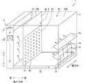
第1実施形態では、運搬用のコンテナ3に収容される調温対象物10を所定の温度に調温可能な調温貯蔵装置1について、図1〜図4を参照して説明する。図面に図示する上下方向は、奥行き方向と幅方向の両方に直交する方向であり、奥行き方向は、上下方向と幅方向の両方に直交する方向である。また、幅方向は、上下方向と奥行き方向の両方に直交する方向である。また、各図には、調温貯蔵装置の構成を理解しやすくするために、コンテナの内蔵部品を実線で表示している。
In the first embodiment, a temperature controlled
調温貯蔵装置1は、筐体の一例であるコンテナ3に空調機2を一体に組み立てた箱体状の装置であり、空調機2がつくり出す空調風により、コンテナ3内の通風空間30における貯蔵室30Aに収容された調温対象物10を所定の温度に調温する。ここで、調温対象物10の一例は、野菜、果物等の青果を入れた多数のプラコンや段ボール箱である。プラコンは、側面及び底面に網状の通気面が形成され、上下方向に嵌め合い積層可能な構成を有するプラスチック箱の略称である。また段ボール箱には、側面及び底面に通気穴が形成されている。貯蔵室30Aを流れる空調風は、この通気穴からプラコンや段ボール箱の内部に対して出入りする。
The temperature controlled
空調機2は、例えば、冷凍サイクル装置、放熱用ファン、空調空気を駆動する送風機21、空調空気が貯蔵室30Aに向けて流れる送風用ダクト22、各機器の作動を制御する制御装置等を空調ユニットとして構成した装置である。冷凍サイクル装置は、例えば電動圧縮機、凝縮器、膨張弁、蒸発器20等を環状に配管接続して構成される冷媒回路であり、電動圧縮機の駆動力により冷媒が循環する。空調機2のうち、冷凍サイクル装置、放熱用ファン、送風機21、及び制御装置はコンテナ3の奥行き方向の一方の端部に装着され、送風用ダクト22はコンテナ3に対して奥行き方向の一方の端部及び下部に装着される。以下、奥行き方向の一方の端部を、説明の便宜上、前部と称する。
The
電動圧縮機は、電動モータと圧縮機構部とを組み合わせて構成される。電動圧縮機は、電動モータにより圧縮機構部が駆動され、制御装置によって電動モータへの印加電圧制御されることで冷凍サイクルの運転状態を制御し、蒸発器20によって空気調和される空気の温度が制御される。送風用ダクト22は、前述したように、コンテナ3の前部で上下方向に延び、さらにコンテナ3の底部で奥行き方向に延びる空気通路を構成する。この送風用ダクト22は、貯蔵室30Aの空気を吸引して再び貯蔵室30Aに戻すための空気通路を構成する部材であり、その内部に送風機21及び蒸発器20が設置されている。
The electric compressor is configured by combining an electric motor and a compression mechanism section. In the electric compressor, the compression mechanism is driven by the electric motor, and the control device controls the voltage applied to the electric motor to control the operating state of the refrigeration cycle, and the temperature of the air conditioned by the
放熱用ファンは、凝縮器とコンテナ3の外部の空気とを強制的に熱交換させる電動ファンであり、制御装置によって風量が制御される。送風機21は、貯蔵室30Aの空気を送風用ダクト22の内部に吸込み、蒸発器20を通過した空気を再び貯蔵室30Aに吹き出させるための電動ファンであり、制御装置によって風量が制御される。
The heat dissipation fan is an electric fan that forcibly exchanges heat between the condenser and the air outside the
また制御装置は、貯蔵室30Aに吹き出される冷気の温度を検出する温度センサから冷気温度を取得する。制御装置は、設定された設定温度と、温度センサから取得した冷気温度に基づいて、貯蔵室30Aの温度が設定温度を維持するように、電動圧縮機の電動モータ等を制御する。例えば、制御装置は、設定温度と冷気温度に基づいて電動モータの通電量をインバータ制御して、圧縮機の回転数を制御する。また、制御装置は、冷凍サイクル装置の運転状態に応じて放熱用ファンの電動モータへの通電をオン、オフ制御して凝縮器の放熱量を制御する。
Further, the control device acquires the cold air temperature from the temperature sensor that detects the temperature of the cold air blown into the
コンテナ3内の通風空間30には、空調機2で作り出した空調風を通風空間30に吹き出させる吹出口23と、通風空間30の空気を空調機2へ戻す吸込口24とが開口している。吹出口23は、送風用ダクト22の下流端に開口する空調風の吹出部であり、通風空間30において、奥行き方向の他方の端部の下端に位置する。以下、奥行き方向の他方の端部を、説明の便宜上、後部と称する。したがって、吹出口23は、通風空間30において後部の下端で開口する。吸込口24は、通風空間30に形成される貯蔵室30Aおよび差圧形成室30Bを流れてきた空調風が通風空間30から流出する吸込部であり、通風空間30において、前部の上端に位置する。したがって、吹出口23と吸込口24は、通風空間30において、対角の位置関係にあり、互いに最も遠く離れた場所に設けられている。通風空間30は、区画板6によって貯蔵室30Aと差圧形成室30Bの2つの室に区画されている。
In the
区画板6は、遮風部6aと整流部6bとを有する。区画板6は、例えばアルミ等の金属材料により形成された板部材である。区画板6は、例えば高さ方向および幅方向に平行な平板である。区画板6は、吸込口24と所定の距離だけ離間して設置されている。区画板6は、吹出口23と吸込口24とがそれぞれ別の室に対して開口するように通風空間30を区画している。より具体的には、区画板6は、吹出口23が貯蔵室30Aに対して開口し、吸込口24が差圧形成室30Bに対して開口するように通風空間30を区画する。換言すれば、区画板6によって区画された通風空間30の2つの室のうち、吹出口23の開口する室が貯蔵室30Aであり、吸込口24の開口する室が差圧形成室30Bである。すなわち、貯蔵室30Aは、吹出口23と差圧形成室30Bとの間に区画形成される室であり、差圧形成室30Bは、貯蔵室30Aと吸込口24との間に区画形成される室である。区画板6は、貯蔵室30Aの体積が差圧形成室30Bよりも大きくなるように通風空間30を区画する。
The
区画板6は、コンテナ3に固定されて設置されている。区画板6は、例えば通風空間30の天井部、壁部および底部に形成されたフレーム部にねじ止めされてあらかじめ決められた位置に固定されている。貯蔵室30Aを区画しているコンテナ3の壁部には、調温対象物10を内部に搬入するための、ドア等の入口部が設けられている。したがって、差圧形成室30Bには調温対象物10を収容できない構成になっている。
The
遮風部6aは、区画板6において空調風の通風を遮断する領域である。遮風部6aは、孔部やスリット等の開口が形成されていない板部として構成され、空調風の通風を遮断できる構造となっている。遮風部6aは、区画板6における通風空間30の天井部から下方の所定の高さまでの所定寸法の部分である。すなわち遮風部6aは、通風空間30の上方で空調風が貯蔵室30Aから差圧形成室30Bへと通風することを阻止する。
The
整流部6bは、区画板6において空調風の通風を許容する領域である。整流部6bは、遮風部6aの下方に設けられている。整流部6bは、例えば複数の孔部61が形成された金属板、いわゆるパンチングメタルとして構成されている。複数の孔部61は、整流部6bの全体にわたって形成されている。図1では複数の孔部61を円形状の貫通孔として示しているが、その形状は限定されるものではなく、例えば孔部61は多角形状の貫通孔であってもよい。複数の孔部61は、例えば整流部6bにおける単位面積当たりの数および大きさが一定となるように形成されている。換言すれば、複数の孔部61は、整流部6bの全領域に片寄りなく形成されている。整流部6bを通過する空調風は、貯蔵室30Aから複数の孔部61を通過して差圧形成室30Bへと流入する。整流部6bにおいて、複数の孔部61が形成されていない部分は、整流部6bを通過する空調風に通風抵抗を与える抵抗部62である。
The rectifying
整流部6bは、貯蔵室30Aの底部から遮風部6aの下端の高さまでの上下寸法を有する。整流部6bの上下寸法は、調温対象物10が収容され得る最大の高さと同等となっている。すなわち、整流部6bの上下寸法によって調温対象物10の好適な最大収容量が決定される。整流部6bの上下寸法は、例えば調温対象物10の収容作業における作業性を考慮して決定される。または、調温貯蔵装置1が貯蔵可能な重量等から調温対象物10の最大収容量が決定され、この最大収容量から整流部6bの上下寸法が決定されていてもよい。
The rectifying
整流部6bは、その開口率が0.5%から30%の間となっている。ここで、開口率とは、整流部6bの面積に対して複数の孔部61の開口面積が占める割合である。整流部6bの開口率は、送風機21が送風する空気の風量に対して適宜設定される。
The
第1案内板5aおよび第2案内板5bは、吹出口から吹き出した空調風の風向を案内する風向案内部材である。以下において、第1案内板5aおよび第2案内板5bを特に区別する必要がない場合、単に案内板と表記する場合がある。案内板は、吹出口23に対応する位置で、吹出口23の幅方向長さ以上の幅方向長さを有する矩形状の板である。したがって、案内板は、吹出口23の幅の全範囲にわたって設けられるものである。案内板は、吹出口から吹き出した空調風の風向が貯蔵室30Aの前部へ向かうように、その角度を設定されて設けられている。調温貯蔵装置1においては、第1案内板5aおよび第2案内板5bの2つの案内板が、上下方向に配置されている。
The
第1案内板5aは、第2案内板5bの下方に設けられた案内板であり、吹出口23から吹き出された空調風の一部を貯蔵室30Aの前部に向かうように案内する。第1案内板5aには、空調風の残りが第2案内板5bへと吹き抜ける際に通過する開口部51が形成されている。開口部51は、第1案内板5aによって案内される空調風の風量と、第2案内板5bによって案内される空調風の風量とが同等になるような開口面積の開口である。
The
第2案内板5bは、第1案内板5aの開口部51を通過した空調風の風向を案内する風向案内部材である。第1案内板5aおよび第2案内板5bは、これら2つの案内板によって分岐した空調風が、整流部6bの高さに対して等間隔で案内される高さにそれぞれ設置されている。
The
案内板が上下方向に2つ設置されていることにより、吹出口23から吹き出された空調風は、流れが上下方向に分配されるように調整されて貯蔵室30Aに対して案内される。これにより、後述の整流部6bの高さ領域における空調風の流れの層がより形成されやすくなる。また案内板は、上下方向に3つ以上設置されていてもよい。案内板は、上下方向に設置される数が多いほどより整流部6bに対して空調風の流れの層を形成しやすくなる。
Since the two guide plates are installed in the vertical direction, the conditioned air blown from the
案内板は、上下方向の角度が変更可能に構成されていてもよい。すなわち、案内板の角度を調整することで、空調風の吹出角度を荷物積載の現場や調温貯蔵装置1の出荷段階や納入段階で所望の角度に調整可能に構成されていてもよい。また、案内板がレール等によって上下方向にスライド可能に設置される構成等により、案内板の高さが変更可能に構成されていてもよい。このような構成によれば、空調風を調温対象物10の配置によってより効率的に調温できる空調風の流れを形成するために、空調風の風向を調整することができる。
The guide plate may be configured so that the vertical angle can be changed. That is, by adjusting the angle of the guide plate, the blowing angle of the conditioned air may be adjusted to a desired angle at the site of luggage loading or at the shipping stage or delivery stage of the temperature controlled
次に、通風空間30を通風する空調風の流れについて図2および図3を用いて説明する。空調機2が作動すると、送風機21が空気の送風を開始する。この送風によって、送風機21の前後で差圧が発生する。すなわち、区画板6から送風機21までの間の空気が送風機21によって吸い出され、送風機21から送風用ダクト22を通過して区画板6に到達するまでの空間に吹き出されるため、区画板6から送風機21までの区間は、他の区間に対して負圧となる。これは、空調機2が吸込口24から差圧形成室30Bの空気を吸い出し、吹出口23から貯蔵室30Aへと吹き出すことによって、差圧形成室30Bが貯蔵室30Aに対して負圧になる、と言い換えることもできる。これにより、差圧形成室30Bと貯蔵室30Aとの間に差圧が形成される。
Next, the flow of the conditioned air that passes through the
吹出口23から貯蔵室30Aに吹き出された空調風は、案内板5a、5bによって整流部6bの方向に案内される。差圧形成室30Bと貯蔵室30Aとの間の差圧により、貯蔵室30A内の空調風は、整流部6bによって吸引される。すなわち、空調風は、整流部6bに形成された複数の孔部61の全部に対して分散して吸い込まれる。また、遮風部6aの高さ領域を通風する空調風は、遮風部6aによって貯蔵室30Aから差圧形成室30Bへの通過を遮られている。したがって、遮風部6aの高さ領域を通風する空調風は遮風部6aによって整流部6bへと導かれるように貯蔵室30A内を流れる。このため、貯蔵室30A内において、整流部6bが形成されている上下方向の領域全体に対して空調風が流れる。すなわち、区画板6に形成された遮風部6aおよび整流部6bによって、貯蔵室30Aを通風する空調風は、整流部6b側に片寄って流れる。換言すれば、貯蔵室30Aには、整流部6bの高さ領域で空調風の流れの層が形成される。
The conditioned air blown from the
以上のように、貯蔵室30Aにおいて形成される空調風の流れの層は、区画板6によって差圧形成室30Bに形成される負圧によるものであり、調温対象物10の量や配置に関わらず形成されるものである。したがって、例えば図2のように調温対象物10が隙間を空けて配置されていても、この隙間を吹き抜ける空調風の流れが支配的となることを抑制でき、調温対象物10に対して均一に空調風が通風する。このように、調温対象物10の量または配置が適宜変更されても、貯蔵室30Aに収容された全ての調温対象物10に対して均一に空調風が通風される。すなわち、調温対象物10の調温ムラを改善することができる。
As described above, the layer of the flow of the conditioned air formed in the
図4に示すように、貯蔵室30Aに収容された調温対象物10は、その高さが整流部6bの高さを超えて収容されてもよい。貯蔵室30Aにおける空調風の流れは、整流部6b側に片寄った流れになるが、一部の空調風は整流部6bの高さよりも高い領域、すなわち遮風部6aの高さ領域を通風した後、整流部6bの上方の孔部61へと吸い込まれる流れを形成する。したがって、調温対象物10が整流部6bの高さよりも高く積載された場合であっても、この一部の空調風の流れによって、全ての調温対象物10に対して空調風を通風させることができる。
As shown in FIG. 4, the
貯蔵室30A内を通風する空調風は、貯蔵室30Aに収容された調温対象物10を所定の温度に調温する。区画板6によって貯蔵室30Aに均一な空調風の流れが形成されているため、空調風は貯蔵室30Aに収容された全ての調温対象物10に対して通過する。したがって、調温対象物10は、すべてムラなく調温される。
The conditioned air that ventilates the inside of the
次に、第1実施形態の調温貯蔵装置1がもたらす作用効果について説明する。調温貯蔵装置1は、調温対象物10が収容される貯蔵室30Aを内部に有するコンテナ3と、コンテナ3に一体に設置されて、送風機21によって貯蔵室30Aに送風される空調風をつくる空調機2とを備える。調温貯蔵装置1は、送風機21によって送風された空調風を貯蔵室30Aに向けて吹き出す吹出口23と、吹出口23と貯蔵室30Aを介して設けられ、空調風を吸い込む吸込口24とを備える。調温貯蔵装置1は、貯蔵室30Aと吸込口24との間に貯蔵室30Aに対して負圧となる差圧形成室30Bを区画形成する区画板6を備える。区画板6は、貯蔵室30Aの天井部から所定の高さまで空調風の通風を遮断する遮風部6aと、遮風部6aの下方に設けられ、空調風が貯蔵室30Aから差圧形成室30Bへ通風抵抗を受けつつ通過可能な整流部6bとを有する。
Next, the function and effect of the temperature controlled
この調温貯蔵装置1によれば、区画板6によって差圧形成室30Bを形成することによって、貯蔵室30Aから差圧形成室30Bに対して空調風が吸い込まれる流れが形成される。区画板6は、遮風部6aと整流部6bを有しているため、区画板6を通過する空調風は、整流部6b側に片寄るようにして流れる。この整流部6b側に片寄った空調風の流れにより、貯蔵室30Aにおける調温対象物10が収容され得る空間に対して空調風を均一に通風させることができる。これにより、調温ムラを改善できる。また、整流部6b側に片寄った空調風の流れは、調温対象物10の量または配置に関わらず形成される。したがって、空調風が調温対象物10の上部や、調温対象物10と調温対象物10との間を吹き抜けることを抑制できる。すなわち、調温対象物10の量や配置による調温性能の低下を抑制でき、これにより作業性を向上できる。さらに、調温対象物10の収容作業においてシャッター等を設置する必要がないため、この点でも作業性を向上できる。以上により、調温ムラを改善するとともに、作業性を向上可能な調温貯蔵装置1を提供することができる。
According to this temperature controlled
区画板6は、コンテナ3の内部においてあらかじめ決められた位置に固定されている。これによれば、区画板6があらかじめコンテナ3に対して備え付けられているため、調温対象物10を収容する際に作業者が区画板6を取り付けるといった作業を行う必要がない。したがって、作業性をより向上することができる。
The
区画板6は、遮風部6aと整流部6bとを一体に有する板状部材である。この構成によれば、遮風部6aと整流部6bとを別体に設置する場合よりも、区画板6をコンテナ3に対して簡単に組み付けることができる。
The
整流部6bは、空調風が通風可能な複数の孔部61を全体にわたって有する。これによれば、整流部6bの全体に対して空調風が吸引される。したがって、貯蔵室30Aにおける整流部6bの高さ領域においてより均一に空調風を通風することができる。したがって、貯蔵室30A内における調温ムラをさらに改善することができる。
The rectifying
調温貯蔵装置1は、貯蔵室30Aに吹き出した空調風を案内する案内板を上下方向に複数有する。これによれば、貯蔵室30Aに吹き出す空調風の流れを上下方向に分配するように調整できるため、整流部6bによる空調風の流れの層をより容易に形成することができる。
The temperature controlled
調温貯蔵装置1は、車両、船舶、航空機の少なくとも1つによって運搬される。これによれば、車両、船舶、航空機の少なくとも1つの移動体によって運搬される運搬用のコンテナに調温貯蔵装置1を適用できる。運搬用のコンテナは、比較的長い期間にわたって調温対象物10を収容するため、調温対象物10を調温ムラなく均一に調温する必要性が高い。したがってこのようなコンテナに対して調温貯蔵装置1を適用することで、調温ムラの改善の効果が大きい。
The temperature controlled
(第2実施形態)
第2実施形態について図5を参照して説明する。第2実施形態において、第1実施形態に係る図面と同一符号を付した構成部品及び説明しない構成は、第1実施形態と同様であり、同様の作用効果を奏するものである。第2実施形態では、第1実施形態と異なる部分のみ説明する。
(Second embodiment)
The second embodiment will be described with reference to FIG. In the second embodiment, the components denoted by the same reference numerals as those in the drawings according to the first embodiment and the configurations not described are the same as those in the first embodiment, and have the same operational effects. In the second embodiment, only parts different from the first embodiment will be described.
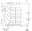
第2実施形態の調温貯蔵装置1は、送風用ダクト222がコンテナ3の前部で上下方向に延び、さらにコンテナ3の天井部で奥行方向に延びる空気通路を形成する。吹出口23は、通風空間30において、奥行き方向の他方の端部の上端に位置する。すなわち、吹出口23は、通風空間30において後部の上端で開口する。吸込口24は、貯蔵室30Aにおいて、前部の下端に位置する。すなわち、空調風は貯蔵室30Aの後部の上端から吹き出し、差圧形成室30Bに形成された差圧によって整流部6bに対して吸引され、差圧形成室30Bの前部の下端から吸い込まれる。
In the temperature controlled
第1案内板5aおよび第2案内板5bは、第1案内板5aが上方で第2案内板5bが下方に位置するように設けられている。案内板は、貯蔵室30Aの後部の上端から吹き出した空調風を整流部6bに対して案内するように角度および位置が調整されている。
The
第2実施形態の調温貯蔵装置1においても、差圧形成室30Bに貯蔵室30Aに対する負圧を付与できる。したがって、貯蔵室30Aにおいて調温対象物10が収容され得る部分に空調風を層のように通風させることができ、第1実施形態の調温貯蔵装置1と同様の作用効果を得ることができる。
Also in the temperature controlled
(第3実施形態)
第3実施形態について図6を参照して説明する。第3実施形態において、第1実施形態に係る図面と同一符号を付した構成部品及び説明しない構成は、第1実施形態と同様であり、同様の作用効果を奏するものである。第3実施形態では、第1実施形態と異なる部分のみ説明する。
(Third Embodiment)
A third embodiment will be described with reference to FIG. In the third embodiment, the components denoted by the same reference numerals as those in the drawings according to the first embodiment and the configurations not described are the same as those in the first embodiment, and have the same operational effects. In the third embodiment, only parts different from the first embodiment will be described.
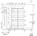
第3実施形態の調温貯蔵装置1は、送風用ダクト222がコンテナ3の天井部で奥行方向に延びる空気通路を形成する。吹出口23は、第2実施形態の調温貯蔵装置と同様に通風空間30において、奥行き方向の他方の端部の上端に位置する。すなわち、吹出口23は、通風空間30において後部の上端で開口する。吸込口24は、差圧形成室30Bにおいて、前部の上端に位置する。したがって、差圧形成室30Bはコンテナ3の前端に位置している。送風機21および蒸発器20は、送風用ダクト222の内部、すなわちコンテナ3の天井部に配置されている。したがって、第3実施形態の調温貯蔵装置1は、貯蔵室30Aの奥行方向の寸法を大きく設定でき、調温対象物10を収容可能な容積を大きくすることができる。
In the temperature controlled
すなわち、空調風は貯蔵室30Aの後部の上端から吹き出し、差圧形成室30Bに形成された差圧によって整流部6bに対して吸引され、差圧形成室30Bの前部の上端から吸い込まれる。第2実施形態の調温貯蔵装置1においても、差圧形成室30Bに貯蔵室30Aに対する負圧を付与できる。したがって、貯蔵室30Aにおいて調温対象物10が収容され得る部分に空調風を層のように通風させることができ、上述の実施形態の調温貯蔵装置1と同様の作用効果を得ることができる。
That is, the conditioned air is blown from the upper end of the rear portion of the
(第4実施形態)
第4実施形態について図7を参照して説明する。第4実施形態において、前述の実施形態に係る図面と同一符号を付した構成部品及び説明しない構成は、前述の実施形態と同様であり、同様の作用効果を奏するものである。第4実施形態では、前述の実施形態と異なる部分のみ説明する。
(Fourth Embodiment)
A fourth embodiment will be described with reference to FIG. In the fourth embodiment, the components denoted by the same reference numerals as those in the drawings according to the above-described embodiment and the components not described are the same as those in the above-described embodiment, and have the same operational effects. In the fourth embodiment, only parts different from the above-described embodiments will be described.
第4実施形態の調温貯蔵装置1は、区画板6に、整流部6bの上部の通風を遮断する封止部材7が設置されている。封止部材7は、ビニルシート等の可撓性のシート部材によって提供することができる。封止部材7は、例えば遮風部6aの下端から吊り下げられるようにして区画板6に固定される。封止部材7は、その上端部分のみが区画板6に固定される。封止部材7は、整流部6bの上端から所定の高さまでの領域を、空調風が通風しないように封止することができる。すなわち、封止部材7は、整流部6bを閉塞し、空調風の孔部61の通過を遮断する。封止部材7は、整流部6bの上端から下端まで、すなわちコンテナ3の底部までを封止可能な上下方向寸法を有していてもよい。
In the temperature controlled
図7に示すように、封止部材7は、調温対象物10を収容した際に調温対象物10の上部に乗せるようにして設置される。収容された調温対象物10の高さが整流部6bの上端の高さよりも低いと、図7に示すように、封止部材7は整流部6bの上端から調温対象物10の上部の高さまでの領域を閉塞する。この整流部6bの封止部材7によって閉塞された領域を上部領域と表記する。封止部材7は、上部領域を閉塞することで、空調風が上部領域を通過することを阻止している。封止部材7は可撓性のシート部材により形成されており、調温対象物10の上部に容易に乗せることができる。このため、調温対象物10の量および配置が変化して調温対象物10の高さが変化した場合でも、上下寸法の範囲内において確実に整流部6bにおける上部領域を閉塞することができる。
As shown in FIG. 7, the sealing
次に第4実施形態の調温貯蔵装置1がもたらす作用効果について説明する。調温貯蔵装置1は、整流部6bの上部領域における空調風の通風を規制する封止部材7を有する。これによれば、調温対象物10の高さが整流部6bの上端よりも低い場合に、整流部6bにおける上端と調温対象物10の上部の高さとの間を空調風が通風することを阻止することができる。したがって、調温対象物10により多くの空調風を通風させることができ、調温性能をさらに向上することができる。
Next, the function and effect of the temperature controlled
(第5実施形態)
第5実施形態について図8を参照して説明する。第5実施形態において、前述の実施形態に係る図面と同一符号を付した構成部品及び説明しない構成は、前述の実施形態と同様であり、同様の作用効果を奏するものである。第5実施形態では、前述の実施形態と異なる部分のみ説明する。
(Fifth Embodiment)
The fifth embodiment will be described with reference to FIG. In the fifth embodiment, the components denoted by the same reference numerals as those in the drawings according to the above-described embodiment and the components not described are the same as those in the above-described embodiment, and have the same operational effects. In the fifth embodiment, only parts different from the above-described embodiments will be described.
第5実施形態の調温貯蔵装置1は、調温対象物10の上部を被覆可能な被覆部材8を有する。被覆部材8は、例えば所定の面積を有する可撓性のシート部材により提供される。被覆部材8は、調温貯蔵装置1の他の部材に固定されてない状態で調温対象物10の上部に設置される。または、被覆部材8は、調温貯蔵装置1の所定の部材、例えば貯蔵室30Aの天井部または壁部等に吊り下げられるように固定されていてもよい。被覆部材8は、調温対象物10の上部を被覆することで空調風の通風を遮断する。したがって、調温対象物10の上部付近に空調風が集中して通風することを抑制することができるため、調温ムラをより改善することができる。
The temperature controlled
(他の実施形態)
この明細書の開示は、例示された実施形態に制限されない。開示は、例示された実施形態と、それらに基づく当業者による変形態様を包含する。例えば、開示は、実施形態において示された部品、要素の組み合わせに限定されず、種々変形して実施することが可能である。開示は、多様な組み合わせによって実施可能である。開示は、実施形態に追加可能な追加的な部分をもつことができる。開示は、実施形態の部品、要素が省略されたものを包含する。開示は、ひとつの実施形態と他の実施形態との間における部品、要素の置き換え、または組み合わせを包含する。開示される技術的範囲は、実施形態の記載に限定されない。開示されるいくつかの技術的範囲は、特許請求の範囲の記載によって示され、さらに特許請求の範囲の記載と均等の意味および範囲内での全ての変更を含むものと解されるべきである。
(Other embodiments)
The disclosure of this specification is not limited to the illustrated embodiments. The disclosure encompasses the illustrated embodiments and variations on them based on them. For example, the disclosure is not limited to the combination of parts and elements shown in the embodiments, and various modifications can be implemented. The disclosure can be implemented in various combinations. The disclosure may have additional parts that may be added to the embodiments. The disclosure includes parts and elements of the embodiments omitted. The disclosure includes replacements or combinations of parts, elements between one embodiment and another. The disclosed technical scope is not limited to the description of the embodiments. It is to be understood that some technical scopes disclosed are shown by the description of the claims and further include meanings equivalent to the description of the claims and all modifications within the scope. ..
上述の実施形態において、整流部6bに形成された複数の孔部61は、全体にわたって数および大きさが一様であるとしたが、数および大きさが領域によって変更されている構成であってもよい。例えば、複数の孔部61は整流部6bの上部ほど数が少なくなるように、または大きさが小さくなるように形成されている構成であってもよい。換言すれば、整流部6bは、上部ほど通風抵抗が大きくなる構成であってもよい。この構成では、整流部6bの上部ほど空調風の通風量が小さくなる。このため、一部の空調風が整流部6bよりも高い位置を通風してしまう場合でも、この一部の空調風が整流部6bの上部に集中して吹き込み調温対象物10の上部に集中して空調風が通風することによる調温ムラを抑制することができる。
In the above-described embodiment, the plurality of
上述の実施形態において、区画板6は遮風部6aと整流部6bが形成された1枚の板部材であるとした。これに代えて、区画板6は、遮風板と整流板の2枚の板部材によって構成されていてもよい。
In the above-described embodiment, the
上述の実施形態において、整流部は、複数の孔部61が形成されているとしたが、空調風が通風抵抗を受けつつ通過できる構成であれば、この構成に限定されない。例えば、整流部は、複数のスリットが並んで形成された構成であってもよい。このとき、複数のスリットは、一様に並んでいる構成であるとより空調風の流速が均一化されるため望ましい。または、整流部は、複数の板が間隙を開けて並べられた構成であってもよい。
In the above-described embodiment, the rectifying unit is formed with the plurality of
上述の実施形態において、区画板6は金属の平板であるとしたが、区画部材としての機能を有していれば遮風部6aまたは整流部6bの少なくとも一方が金属以外の板部材でもよい。また、区画板6の代わりに、遮風部6aまたは整流部6bの少なくとも一方にシート部材を適用してもよい。例えば、整流部6bに孔部またはスリット等が形成されたビニルシートを区画部材として適用してもよい。
Although the
上述の実施形態において、区画板6はコンテナ3に対して固定されている構成であるとした。これに代えて、区画板6はコンテナ3に対して移動可能な構成であってもよい。例えば、コンテナ3に設置されたレール部に区画板6が取り付けられ、このレール部に沿って区画板6が奥行き方向に移動可能な構成であってもよい。この構成であれば、貯蔵室30Aの体積を変更できるため、調温対象物10の収容可能量を任意に変更することができる。
In the above embodiment, the
上述の実施形態において、調温貯蔵装置1は風向調整板を備えるとしたが、風向調整板を備えない構成であってもよい。風向調整板を備えない場合であっても、貯蔵室30Aに空調風が吹き出せば、区画板6によって貯蔵室30Aの空調風が吸引されるため、整流部6bの高さ領域において空調風の流れの層を形成することができる。
In the above-described embodiment, the temperature controlled
1…調温貯蔵装置、 2…空調機、 3…コンテナ(筐体)、5a…第1案内板(風向案内部材)、 5b…第2案内板(風向案内部材)、 6…区画板(区画部材)、 6a…遮風部、 6b…整流部、 61…孔部、 7…封止部材、 8…被覆部材、 10…調温対象物、 21…送風機、 23…吹出口(吹出部)、 24…吸込口(吸込部)、 30A…貯蔵室、 30B…差圧形成室、
DESCRIPTION OF
Claims (9)
送風機(21)を有し、前記筐体に一体に設置されて、前記送風機によって前記貯蔵室に送風される空調風をつくる空調機(2)と、
前記送風機によって送風された前記空調風を前記貯蔵室に向けて吹き出す吹出部(23)と、
前記貯蔵室を通過した前記空調風を吸い込む吸込部(24)と、
前記調温対象物よりも前記吸込部側に設けられ、前記貯蔵室と前記吸込部との間に前記貯蔵室に対して負圧となる差圧形成室(30B)を区画形成する区画部材(6)と、
を備え、
前記区画部材は、
前記貯蔵室の天井部から所定の高さまで前記空調風の通風を遮断する遮風部(6a)と、
最大収容量収容された場合の前記調温対象物の高さと同等の上下寸法で前記遮風部の下方に設けられ、前記空調風が前記貯蔵室から前記差圧形成室へ通風抵抗を受けつつ通過可能な整流部(6b)と、
を前記調温対象物と別体に有する調温貯蔵装置。 A housing (3) having therein a storage chamber (30A) in which the temperature control object (10) is housed;
An air conditioner (2) that has a blower (21) and is integrally installed in the housing, and creates conditioned air that is blown into the storage chamber by the blower;
A blower (23) for blowing out the conditioned air blown by the blower toward the storage chamber;
A suction unit (24) for sucking the conditioned air that has passed through the storage chamber;
A partition member that is provided closer to the suction unit than the temperature control target and that partitions and forms a differential pressure forming chamber (30B) between the storage chamber and the suction unit, which is a negative pressure with respect to the storage chamber (30B). 6),
Equipped with
The partition member is
An air shield (6a) for blocking ventilation of the conditioned air from the ceiling of the storage room to a predetermined height;
It is provided below the wind shield with a vertical dimension equivalent to the height of the temperature controlled object when the maximum storage amount is stored, and while the conditioned air receives ventilation resistance from the storage chamber to the differential pressure forming chamber. A rectifying part (6b) that can pass through,
A temperature control storage device having the temperature control object separately from the temperature control target object .
Priority Applications (4)
| Application Number | Priority Date | Filing Date | Title |
|---|---|---|---|
| JP2017009563A JP6724802B2 (en) | 2017-01-23 | 2017-01-23 | Temperature control storage device |
| CN201780084103.2A CN110199164A (en) | 2017-01-23 | 2017-09-12 | Temperature adjustment storage facilities |
| PCT/JP2017/032752 WO2018135034A1 (en) | 2017-01-23 | 2017-09-12 | Temperature regulating storage device |
| PH12019501229A PH12019501229A1 (en) | 2017-01-23 | 2019-05-31 | Temperature regulation storage device |
Applications Claiming Priority (1)
| Application Number | Priority Date | Filing Date | Title |
|---|---|---|---|
| JP2017009563A JP6724802B2 (en) | 2017-01-23 | 2017-01-23 | Temperature control storage device |
Publications (3)
| Publication Number | Publication Date |
|---|---|
| JP2018119697A JP2018119697A (en) | 2018-08-02 |
| JP2018119697A5 JP2018119697A5 (en) | 2019-05-09 |
| JP6724802B2 true JP6724802B2 (en) | 2020-07-15 |
Family
ID=62908001
Family Applications (1)
| Application Number | Title | Priority Date | Filing Date |
|---|---|---|---|
| JP2017009563A Expired - Fee Related JP6724802B2 (en) | 2017-01-23 | 2017-01-23 | Temperature control storage device |
Country Status (4)
| Country | Link |
|---|---|
| JP (1) | JP6724802B2 (en) |
| CN (1) | CN110199164A (en) |
| PH (1) | PH12019501229A1 (en) |
| WO (1) | WO2018135034A1 (en) |
Families Citing this family (1)
| Publication number | Priority date | Publication date | Assignee | Title |
|---|---|---|---|---|
| CN112781401B (en) * | 2019-11-06 | 2023-07-25 | 广东美的白色家电技术创新中心有限公司 | Heat transfer device wind channel subassembly and refrigeration plant |
Family Cites Families (15)
| Publication number | Priority date | Publication date | Assignee | Title |
|---|---|---|---|---|
| JPS55110867A (en) * | 1979-02-20 | 1980-08-26 | Matsuhashi Reinetsu Kogyo Kk | Differential pressure ventilating refrigerator |
| JPH0754788Y2 (en) * | 1991-06-12 | 1995-12-18 | 日本フルハーフ株式会社 | Packing box for frozen transportation of flowers etc. |
| JP3807518B2 (en) * | 1996-12-26 | 2006-08-09 | 大成建設株式会社 | Refrigerated warehouse |
| JP2004125211A (en) * | 2002-09-30 | 2004-04-22 | Matsushita Refrig Co Ltd | Refrigerator |
| KR100916217B1 (en) * | 2008-12-03 | 2009-09-08 | 주식회사 이에스티 | Refrigerator car using cold storage material |
| CA2688005A1 (en) * | 2009-01-30 | 2010-07-30 | Husky Injection Molding Systems Ltd. | Hydraulic reservoir tank |
| CN101670924A (en) * | 2009-09-16 | 2010-03-17 | 烟台冰轮股份有限公司 | Movable energy-saving differential pressure precooling device |
| CN103075861B (en) * | 2012-12-27 | 2014-12-17 | 合肥美的电冰箱有限公司 | Air-cooling refrigerator |
| JP6187317B2 (en) * | 2014-02-28 | 2017-08-30 | 株式会社デンソー | Temperature control storage device |
| CN104197606B (en) * | 2014-08-26 | 2016-03-09 | 广东星星制冷设备有限公司 | A kind of refrigerator with wind deflector |
| CN204227798U (en) * | 2014-10-10 | 2015-03-25 | 黄河彬 | For the cold air damping device in refrigerating chamber |
| JP2016161179A (en) * | 2015-02-27 | 2016-09-05 | 株式会社デンソー | Temperature adjusting storage device |
| CN204739829U (en) * | 2015-06-08 | 2015-11-04 | 上海海洋大学 | Improve scattered class of baffle device of freezer air current homogeneity |
| CN204880923U (en) * | 2015-06-19 | 2015-12-16 | 邱丽香 | Case is air -dried in cooling |
| CN105043080B (en) * | 2015-07-06 | 2017-04-05 | 南京师范大学 | A kind of vertical ventilation type heat pump thermostatic equipment |
-
2017
- 2017-01-23 JP JP2017009563A patent/JP6724802B2/en not_active Expired - Fee Related
- 2017-09-12 CN CN201780084103.2A patent/CN110199164A/en active Pending
- 2017-09-12 WO PCT/JP2017/032752 patent/WO2018135034A1/en active Application Filing
-
2019
- 2019-05-31 PH PH12019501229A patent/PH12019501229A1/en unknown
Also Published As
| Publication number | Publication date |
|---|---|
| PH12019501229A1 (en) | 2019-12-02 |
| WO2018135034A1 (en) | 2018-07-26 |
| JP2018119697A (en) | 2018-08-02 |
| CN110199164A (en) | 2019-09-03 |
Similar Documents
| Publication | Publication Date | Title |
|---|---|---|
| JP6038328B2 (en) | Air conditioner indoor unit | |
| JP6729009B2 (en) | Showcase | |
| US20190186759A1 (en) | Indoor unit | |
| JP4800237B2 (en) | Electronic device storage device | |
| JP6724802B2 (en) | Temperature control storage device | |
| JP2003130531A (en) | Refrigerator | |
| JP2015052441A (en) | Freezing car | |
| JP6187317B2 (en) | Temperature control storage device | |
| JP6888924B2 (en) | Air conditioning system | |
| JP5957762B2 (en) | Open showcase | |
| JP4370461B2 (en) | Indoor unit of air conditioner | |
| WO2018061071A1 (en) | Outdoor unit of air conditioner | |
| JP2016161179A (en) | Temperature adjusting storage device | |
| US20200298671A1 (en) | Grill for transport refrigeration unit | |
| JP5899561B2 (en) | Temperature control system | |
| JP5914801B2 (en) | Open showcase | |
| JP2016099034A (en) | Air conditioning device, adjustment method of air conditioning device and manufacturing method of air conditioning facility | |
| JP5284712B2 (en) | Banana ripening equipment | |
| JP6713836B2 (en) | refrigerator | |
| JP6511991B2 (en) | Cold storage | |
| KR100566800B1 (en) | air conditioner | |
| JP2010266084A (en) | Blower device in box type cargo bed including refrigerating device | |
| JP2018066550A (en) | Allocation variable structure for air conditioner ventilation port | |
| NL2004589C2 (en) | Device for forming an air-curtain for screening the entrance of an acclimated space, acclimated space and transport vehicle. | |
| JP3318829B2 (en) | Air conditioner |
Legal Events
| Date | Code | Title | Description |
|---|---|---|---|
| A521 | Request for written amendment filed |
Free format text: JAPANESE INTERMEDIATE CODE: A523 Effective date: 20190320 |
|
| A621 | Written request for application examination |
Free format text: JAPANESE INTERMEDIATE CODE: A621 Effective date: 20190320 |
|
| A131 | Notification of reasons for refusal |
Free format text: JAPANESE INTERMEDIATE CODE: A131 Effective date: 20200212 |
|
| A521 | Request for written amendment filed |
Free format text: JAPANESE INTERMEDIATE CODE: A523 Effective date: 20200410 |
|
| TRDD | Decision of grant or rejection written | ||
| A01 | Written decision to grant a patent or to grant a registration (utility model) |
Free format text: JAPANESE INTERMEDIATE CODE: A01 Effective date: 20200526 |
|
| A61 | First payment of annual fees (during grant procedure) |
Free format text: JAPANESE INTERMEDIATE CODE: A61 Effective date: 20200608 |
|
| R151 | Written notification of patent or utility model registration |
Ref document number: 6724802 Country of ref document: JP Free format text: JAPANESE INTERMEDIATE CODE: R151 |
|
| LAPS | Cancellation because of no payment of annual fees |