JP6720894B2 - Steel sheet cooling method, steel sheet cooling device, and steel sheet manufacturing method - Google Patents
Steel sheet cooling method, steel sheet cooling device, and steel sheet manufacturing method Download PDFInfo
- Publication number
- JP6720894B2 JP6720894B2 JP2017038973A JP2017038973A JP6720894B2 JP 6720894 B2 JP6720894 B2 JP 6720894B2 JP 2017038973 A JP2017038973 A JP 2017038973A JP 2017038973 A JP2017038973 A JP 2017038973A JP 6720894 B2 JP6720894 B2 JP 6720894B2
- Authority
- JP
- Japan
- Prior art keywords
- cooling
- plate
- steel sheet
- steel
- steel plate
- Prior art date
- Legal status (The legal status is an assumption and is not a legal conclusion. Google has not performed a legal analysis and makes no representation as to the accuracy of the status listed.)
- Active
Links
- 229910000831 Steel Inorganic materials 0.000 title claims description 145
- 239000010959 steel Substances 0.000 title claims description 145
- 238000001816 cooling Methods 0.000 title claims description 126
- 238000004519 manufacturing process Methods 0.000 title description 16
- 238000000034 method Methods 0.000 claims description 17
- 239000000498 cooling water Substances 0.000 claims description 11
- 238000005098 hot rolling Methods 0.000 claims description 3
- 238000005507 spraying Methods 0.000 claims description 2
- 239000011295 pitch Substances 0.000 description 37
- 238000010438 heat treatment Methods 0.000 description 13
- 238000010586 diagram Methods 0.000 description 12
- XLYOFNOQVPJJNP-UHFFFAOYSA-N water Substances O XLYOFNOQVPJJNP-UHFFFAOYSA-N 0.000 description 8
- 230000008602 contraction Effects 0.000 description 6
- 230000007547 defect Effects 0.000 description 5
- 238000012937 correction Methods 0.000 description 4
- 238000009826 distribution Methods 0.000 description 4
- 230000000052 comparative effect Effects 0.000 description 3
- 230000000694 effects Effects 0.000 description 3
- 238000005096 rolling process Methods 0.000 description 3
- 238000007796 conventional method Methods 0.000 description 2
- 230000007423 decrease Effects 0.000 description 2
- 230000002950 deficient Effects 0.000 description 2
- 238000013461 design Methods 0.000 description 2
- 239000000463 material Substances 0.000 description 2
- 230000000452 restraining effect Effects 0.000 description 2
- 238000003466 welding Methods 0.000 description 2
- 238000005520 cutting process Methods 0.000 description 1
- 238000009795 derivation Methods 0.000 description 1
- 238000002474 experimental method Methods 0.000 description 1
- 238000000605 extraction Methods 0.000 description 1
- 238000005259 measurement Methods 0.000 description 1
- 238000011002 quantification Methods 0.000 description 1
- 238000010791 quenching Methods 0.000 description 1
- 230000000171 quenching effect Effects 0.000 description 1
- 230000001603 reducing effect Effects 0.000 description 1
- 238000003303 reheating Methods 0.000 description 1
- 238000010008 shearing Methods 0.000 description 1
- 238000004904 shortening Methods 0.000 description 1
- 239000007921 spray Substances 0.000 description 1
Images


Classifications
-
- B—PERFORMING OPERATIONS; TRANSPORTING
- B21—MECHANICAL METAL-WORKING WITHOUT ESSENTIALLY REMOVING MATERIAL; PUNCHING METAL
- B21B—ROLLING OF METAL
- B21B45/00—Devices for surface or other treatment of work, specially combined with or arranged in, or specially adapted for use in connection with, metal-rolling mills
- B21B45/02—Devices for surface or other treatment of work, specially combined with or arranged in, or specially adapted for use in connection with, metal-rolling mills for lubricating, cooling, or cleaning
- B21B45/0203—Cooling
- B21B45/0209—Cooling devices, e.g. using gaseous coolants
- B21B45/0215—Cooling devices, e.g. using gaseous coolants using liquid coolants, e.g. for sections, for tubes
- B21B45/0218—Cooling devices, e.g. using gaseous coolants using liquid coolants, e.g. for sections, for tubes for strips, sheets, or plates
-
- B—PERFORMING OPERATIONS; TRANSPORTING
- B21—MECHANICAL METAL-WORKING WITHOUT ESSENTIALLY REMOVING MATERIAL; PUNCHING METAL
- B21B—ROLLING OF METAL
- B21B37/00—Control devices or methods specially adapted for metal-rolling mills or the work produced thereby
- B21B37/74—Temperature control, e.g. by cooling or heating the rolls or the product
-
- B—PERFORMING OPERATIONS; TRANSPORTING
- B21—MECHANICAL METAL-WORKING WITHOUT ESSENTIALLY REMOVING MATERIAL; PUNCHING METAL
- B21B—ROLLING OF METAL
- B21B45/00—Devices for surface or other treatment of work, specially combined with or arranged in, or specially adapted for use in connection with, metal-rolling mills
- B21B45/02—Devices for surface or other treatment of work, specially combined with or arranged in, or specially adapted for use in connection with, metal-rolling mills for lubricating, cooling, or cleaning
- B21B45/0203—Cooling
- B21B45/0209—Cooling devices, e.g. using gaseous coolants
- B21B45/0215—Cooling devices, e.g. using gaseous coolants using liquid coolants, e.g. for sections, for tubes
- B21B45/0233—Spray nozzles, Nozzle headers; Spray systems
-
- B—PERFORMING OPERATIONS; TRANSPORTING
- B21—MECHANICAL METAL-WORKING WITHOUT ESSENTIALLY REMOVING MATERIAL; PUNCHING METAL
- B21B—ROLLING OF METAL
- B21B2275/00—Mill drive parameters
- B21B2275/02—Speed
- B21B2275/06—Product speed
-
- B—PERFORMING OPERATIONS; TRANSPORTING
- B21—MECHANICAL METAL-WORKING WITHOUT ESSENTIALLY REMOVING MATERIAL; PUNCHING METAL
- B21B—ROLLING OF METAL
- B21B37/00—Control devices or methods specially adapted for metal-rolling mills or the work produced thereby
- B21B37/74—Temperature control, e.g. by cooling or heating the rolls or the product
- B21B37/76—Cooling control on the run-out table
Landscapes
- Engineering & Computer Science (AREA)
- Mechanical Engineering (AREA)
- Heat Treatment Of Strip Materials And Filament Materials (AREA)
- Metal Rolling (AREA)
Description
本発明は、熱間圧延された高温の鋼板を、ロールにより拘束した状態で通過冷却を実施する制御冷却に関する。特に板厚が10mm以下と薄く、且つ板幅が3000mm以上厚鋼板に対して、歪の少ない鋼板を製造することができる、鋼板の冷却方法および冷却装置ならびに鋼板の製造方法に関する。 TECHNICAL FIELD The present invention relates to control cooling for carrying out passage cooling in a state in which a hot-rolled high-temperature steel plate is restrained by rolls. Particularly, the present invention relates to a steel plate cooling method, a cooling device, and a steel plate manufacturing method capable of manufacturing a steel plate having a plate thickness as thin as 10 mm or less and a plate width of 3000 mm or more and having less distortion.
鋼板の製造に当たっては、鋼板に要求される機械的性質、特に強度と靭性を確保する必要がある。これを達成するために、圧延後の高温の鋼板をそのまま冷却したり、一旦室温まで空冷して、オフラインで再加熱・焼入れしたりする作業が行われる。この冷却では、鋼板に要求される材質上の特性を確保するために、冷却速度を大きくすることが必要である。同時に、材質の均一性を確保し、冷却時の歪み(冷却歪)の発生を抑制するために冷却が鋼板面全体にわたって均一に行われることが重要である。冷却歪が発生した場合、冷却後の鋼板をローラー矯正機やプレスなどの矯正機を用いて平坦度を確保することが必要となるため、追加工程が発生することから納期短縮の大きな障害となる。 In manufacturing a steel sheet, it is necessary to secure the mechanical properties required for the steel sheet, particularly strength and toughness. In order to achieve this, a work of cooling the hot steel sheet after rolling as it is, or once air-cooling to room temperature and reheating and quenching off-line is performed. In this cooling, it is necessary to increase the cooling rate in order to secure the material properties required for the steel sheet. At the same time, it is important that the cooling be performed uniformly over the entire surface of the steel sheet in order to ensure the uniformity of the material and suppress the occurrence of distortion (cooling distortion) during cooling. When cooling distortion occurs, it is necessary to secure the flatness of the cooled steel plate by using a straightening machine such as a roller straightening machine or a press, which causes an additional process, which is a major obstacle to shortening the delivery time. ..
これに対応して、現在、鋼板の冷却は複数のロールにより鋼板を拘束し、その拘束ロール間に冷却ノズルを配置して、鋼板を通過させながら冷却する手法が広く行われており、これにより歪の少ない鋼板を製造している。 Correspondingly, at present, for cooling the steel sheet, a method is widely used in which the steel sheet is constrained by a plurality of rolls, a cooling nozzle is arranged between the constraining rolls, and the steel sheet is cooled while passing through it. We manufacture steel plates with low distortion.
このような方法で制御冷却する理由として、通過冷却とすることで短い設備長で冷却が可能になるため、初期投資コストの抑制が可能であることが挙げられる。また、拘束ロールは冷却中の鋼板上下面や鋼板面内の温度分布の不均一に起因して発生する歪を押さえ込み、且つロール間に冷却ノズルを配置することにより、冷却装置外部に冷却水が出ないようにして、鋼板上に冷却水が滞留する事を防止している。 The reason why the controlled cooling is performed by such a method is that the passage cooling enables cooling with a short equipment length, and thus the initial investment cost can be suppressed. Further, the constraining roll suppresses distortion generated due to uneven temperature distribution in the upper and lower surfaces of the steel sheet or the steel sheet surface during cooling, and by disposing a cooling nozzle between the rolls, cooling water is provided outside the cooling device. The cooling water is prevented from staying on the steel plate by preventing it from coming out.
以上の観点から、たとえば特許文献1には、冷却後の鋼板温度分布の不均一に起因した形状不良に対して、冷却後の鋼板の温度分布の測定から鋼板に発生する残留応力を予測することで、矯正の必要可否を判断する方法が記載されている。 From the above point of view, for example, in Patent Document 1, for a shape defect due to non-uniformity of the steel plate temperature distribution after cooling, the residual stress generated in the steel plate is predicted from the measurement of the temperature distribution of the steel plate after cooling. Describes a method for determining whether or not correction is necessary.
また、特許文献2には、水冷中に発生するC反りを抑制する観点で、拘束ロールに着目し、そのロールピッチ、鋼板厚みの関数として必要な拘束ロールの拘束力の範囲で負荷をかけることにより、平坦度のよい鋼板の製造方法について記載されている。
Further, in
上記で説明したような手法により歪の少ない鋼板が製造できるようになったものの、幅方向や上下面の温度均一性を確保して冷却しても、依然として歪が発生することがある。そこで本発明者らが歪の発生について検討した結果、水冷時の鋼板幅方向の収縮による座屈変形に起因して冷却歪が発生することがわかった。座屈変形に起因する冷却歪は、板厚が薄く且つ板幅が広い鋼板の場合、上記で説明したような手法による低減効果が発現しにくく、特に板厚が10mm以下であり且つ板幅3000mm以上の鋼板の冷却時には、幅方向や上下面の温度均一性を確保して冷却しても歪が発生するということがわかった。 Although a steel plate with less strain can be manufactured by the method as described above, the strain may still occur even if the steel plate is cooled while ensuring the temperature uniformity in the width direction and the upper and lower surfaces. Therefore, as a result of the inventors' studying the occurrence of strain, it was found that cooling strain occurs due to buckling deformation due to contraction in the steel sheet width direction during water cooling. In the case of a steel plate having a thin plate thickness and a wide plate width, the cooling strain due to buckling deformation is unlikely to exhibit the reducing effect by the method described above, and particularly the plate thickness is 10 mm or less and the plate width is 3000 mm. It was found that when the above steel sheet is cooled, distortion occurs even if it is cooled while ensuring temperature uniformity in the width direction and the upper and lower surfaces.
水冷時の鋼板幅方向の収縮による座屈変形は、これまでに想定されている上下面の温度偏差による歪と異なるメカニズムであるため、従来の手法で冷却を行っても歪が発生すると考えられる。特許文献1のような鋼板の冷却後の温度分布から予測する方法では、予測した板形状よりも大きな変形が発生する。そのため予測が外れ、矯正の発生率の削減は困難である。また、特許文献2では、上下面の温度偏差起因の歪の抑制は可能であるものの、水冷時に伴う板幅収縮に起因した座屈変形は考慮してないため、板厚が薄く且つ板幅が広い領域に関して効果が発現しない。
Buckling deformation due to contraction in the steel sheet width direction during water cooling is a mechanism different from the strain caused by temperature deviation of the upper and lower surfaces assumed so far, so it is considered that strain occurs even if cooling is performed by the conventional method. .. In the method of predicting the temperature distribution of the steel sheet after cooling as in Patent Document 1, a larger deformation than the predicted plate shape occurs. Therefore, the prediction is wrong and it is difficult to reduce the incidence of correction. Further, in
そこで本発明は、上記従来技術の問題点を解決することを課題とし、熱間圧延後の鋼板をロールで拘束しながら冷却する制御冷却において、歪の少ない鋼板の冷却方法および鋼板の冷却装置ならびに鋼板の製造方法を提供することを目的とする。 Therefore, the present invention has an object to solve the problems of the above-mentioned conventional techniques, in controlled cooling while cooling the steel sheet after hot rolling while restraining the steel sheet with rolls, a method for cooling a steel sheet with less distortion and a cooling device for the steel sheet, and An object is to provide a method for manufacturing a steel sheet.
本発明の要旨は、以下の通りである。
[1]鋼板搬送方向に所定のピッチに配置される複数のロールにより鋼板を拘束した状態で搬送し、複数のロール間に配置される冷却ノズルにより鋼板の上下面に冷却水を噴射して鋼板を冷却する鋼板の冷却方法において、
下記式(1)を満足する通板速度Vで冷却することを特徴とする鋼板の冷却方法。
V>2.21×10⁻⁵×Cv×L3×t−2×(24.2+204.3×(L/W)2)−1・・・(1)
ただし、式(1)において、
V:通板速度(m/s)
Cv:板厚方向の鋼板平均温度に対する冷却速度(℃/s)
L:ロールピッチ(m)
t:板厚(m)
W:板幅(m)
である。
[2]板厚tは10mm以下であることを特徴とする[1]に記載の鋼板の冷却方法。
[3]板幅Wは3000mm以上であることを特徴とする[1]または[2]に記載の鋼板の冷却方法。
[4]鋼板搬送方向に所定のピッチで配置されて、鋼板を拘束して搬送する複数のロールと、
複数のロール間に配置されて、鋼板の上下面に冷却水を噴射して鋼板を冷却する冷却ノズルと、
下記式(1)を満足するように通板速度Vを制御する制御機構と
を備えることを特徴とする鋼板の冷却装置。
V>2.21×10⁻⁵×Cv×L3×t−2×(24.2+204.3×(L/W)2)−1・・・(1)
ただし、式(1)において、
V:通板速度(m/s)
Cv:板厚方向の鋼板平均温度に対する冷却速度(℃/s)
L:ロールピッチ(m)
t:板厚(m)
W:板幅(m)
である。
[5]板厚tは10mm以下であることを特徴とする[4]に記載の鋼板の冷却装置。
[6]板幅Wは3000mm以上であることを特徴とする[4]または[5]に記載の鋼板の冷却装置。
[7]熱間圧延後の鋼板を[1]〜[3]のいずれかに記載の冷却方法を用いて冷却し、鋼板を製造することを特徴とする鋼板の製造方法。
The gist of the present invention is as follows.
[1] A steel plate is conveyed while being constrained by a plurality of rolls arranged at a predetermined pitch in the steel plate conveyance direction, and cooling water is jetted onto the upper and lower surfaces of the steel plate by a cooling nozzle arranged between the plurality of rolls. In the cooling method of the steel sheet for cooling
A method for cooling a steel sheet, comprising cooling at a sheet passing speed V satisfying the following formula (1).
V>2.21×10 −5 ×Cv×L 3 ×t −2 ×(24.2+204.3×(L/W) 2 ) −1 (1)
However, in equation (1),
V: Plate passing speed (m/s)
Cv: Cooling rate (°C/s) with respect to the average temperature of the steel plate in the plate thickness direction
L: Roll pitch (m)
t: plate thickness (m)
W: Board width (m)
Is.
[2] The method for cooling a steel sheet according to [1], wherein the plate thickness t is 10 mm or less.
[3] The method for cooling a steel plate according to [1] or [2], wherein the plate width W is 3000 mm or more.
[4] A plurality of rolls arranged at a predetermined pitch in the steel plate transport direction to constrain and transport the steel plate,
A cooling nozzle which is arranged between a plurality of rolls and cools the steel sheet by spraying cooling water on the upper and lower surfaces of the steel sheet,
A cooling mechanism for a steel sheet, comprising: a control mechanism that controls the strip passing speed V so as to satisfy the following formula (1).
V>2.21×10 −5 ×Cv×L 3 ×t −2 ×(24.2+204.3×(L/W) 2 ) −1 (1)
However, in equation (1),
V: Plate passing speed (m/s)
Cv: Cooling rate (°C/s) with respect to the average temperature of the steel plate in the plate thickness direction
L: Roll pitch (m)
t: plate thickness (m)
W: Board width (m)
Is.
[5] The steel plate cooling device according to [4], wherein the plate thickness t is 10 mm or less.
[6] The steel plate cooling device according to [4] or [5], wherein the plate width W is 3000 mm or more.
[7] A method for producing a steel sheet, comprising cooling the steel sheet after hot rolling using the cooling method according to any one of [1] to [3] to produce a steel sheet.
本発明によれば、歪の少ない鋼板の製造が可能となる。特に厚鋼板のオフライン熱処理に適用することでその効果を発揮できる。 According to the present invention, it is possible to manufacture a steel plate with little distortion. Especially, the effect can be exhibited by applying it to the off-line heat treatment of thick steel plate.
まず、冷却歪の原因と考えられる水冷時の鋼板幅方向の収縮による座屈変形について説明する。図1は、本発明の鋼板の冷却装置を用いた製造設備の一部の構成を示す模式図である。圧延機ラインで製造した所定の板厚の鋼板1を、図1の製造ラインに搬送する。加熱炉10により鋼板1を所定の温度に加熱した後、複数のロール2により拘束しながら鋼板1を搬送させ、各ロール2間に設置されている複数の冷却ノズル3により冷却を行う。なお、図中の矢印は鋼板の搬送方向である。また、ロール2および冷却ノズル3は鋼板1の上下面に設置される。
First, buckling deformation due to contraction in the width direction of the steel sheet during water cooling, which is considered to be the cause of cooling distortion, will be described. FIG. 1 is a schematic diagram showing a partial configuration of a manufacturing facility using a steel sheet cooling device of the present invention. The steel plate 1 having a predetermined plate thickness manufactured on the rolling mill line is conveyed to the manufacturing line in FIG. After the steel plate 1 is heated to a predetermined temperature by the
図2(a)は、本発明の鋼板の冷却装置の構成を示す模式図である。図2(a)に示すように、鋼板1は搬送方向に沿って、ロール2−0、ロール2−1、…ロール2−i、ロール2−nといった、複数のロール2により上下面を拘束されている。各ロール2間には、冷却ノズル3が鋼板1の上下面にそれぞれ設置されている。
FIG. 2A is a schematic diagram showing the configuration of the steel plate cooling device of the present invention. As shown in FIG. 2( a ), the steel plate 1 restrains the upper and lower surfaces by a plurality of
図2(b)は、鋼板冷却時における鋼板の板幅Wの変化を説明する図であり、図2(a)に示す鋼板の冷却装置内を通過する際の、鋼板1の板幅Wの変化を上から見た図である。各ロール2を通過する際の鋼板1の板幅をW、ロールピッチをLとすると、水冷により鋼板1は収縮する。例えば、ロール2−0からロール2−1へ鋼板が移動した場合、図2(b)に示すように、板幅はΔW(Δ=W0−W1、なお、Wo:ロール2−0を通過する際の板幅、W1:ロール2−1を通過する際の板幅である。)だけ収縮する。このとき、板幅の広い鋼板と板幅の狭い鋼板が同じ幅となるように接合させているのと同じ状態となるため、板幅の広い部分(例えば板幅Wo)は大きな圧縮応力を受ける。この圧縮応力による鋼板の変形を本発明では座屈変形とよぶ。
FIG. 2B is a diagram for explaining changes in the plate width W of the steel plate during cooling of the steel plate, and shows the plate width W of the steel plate 1 when passing through the cooling device for the steel plate shown in FIG. It is the figure which looked at a change from the top. When the plate width of the steel plate 1 when passing through each
このとき、通板速度が遅い若しくは冷却速度が速い場合は、その搬送方向に対する収縮勾配ΔW/Lが急峻となることで大きな圧縮応力が発生し、座屈変形が発生しやすくなる。また、板厚が薄く且つ板幅が広い場合は、板の剛性が低くなることで、圧縮応力による耐性が低くなり、同じく座屈変形が発生しやすくなる。 At this time, when the plate passing speed is slow or the cooling speed is fast, the contraction gradient ΔW/L with respect to the conveying direction becomes steep, so that a large compressive stress is generated and buckling deformation easily occurs. Further, when the plate thickness is thin and the plate width is wide, the rigidity of the plate is low, so that the resistance to the compressive stress is low and the buckling deformation is likely to occur.
そこで、上記の板幅Wの収縮メカニズムを確認するために、実際の製造ラインにおいて、通板速度V、板厚t、板幅Wや冷却速度Cvなど様々な条件で冷却した鋼板の形状と各冷却条件との関係について調査した。具体的には、圧延機ラインで製造した板厚6mm〜10mmの鋼板1を、図1の製造ラインに搬送し、加熱炉(ハースロール加熱炉)10により950℃まで加熱したのちに、ロール2により拘束しながら、冷却ノズル3により100℃まで冷却を行った。冷却後の鋼板形状から座屈変形したかどうかの判断を行った。
Therefore, in order to confirm the contraction mechanism of the plate width W, in the actual manufacturing line, the shape and the shape of the steel plate cooled under various conditions such as the plate passing speed V, the plate thickness t, the plate width W, and the cooling speed Cv. The relationship with the cooling conditions was investigated. Specifically, the steel plate 1 having a plate thickness of 6 mm to 10 mm manufactured by a rolling mill line is conveyed to the manufacturing line of FIG. 1 and heated to 950° C. by a heating furnace (hearth roll heating furnace) 10, and then the
図3は、形状不良が発生した鋼板の形状を示す一例の図であり、鋼板1のエッジ部にいわゆる耳波と呼ばれる形状不良が発生していた。この耳波形状の不良を、図4および下記式(2)に示す定義で表される急峻度λ(%)を用いて定量化した。なお、耳波は一ヶ所に発生するわけではなく、鋼板の両端部に複数発生する。そこで、下記式(2)におけるδ/Pの値は、鋼板両端部に発生した全ての耳波の平均値とする。
λ=(δ/P)×100・・・(2)
ただし、式(2)において、
λ:急峻度(%)
δ:波高さ
P:波ピッチ
である。
FIG. 3 is an example of a shape of a steel sheet in which a shape defect has occurred, and a shape defect called a so-called selvage wave has occurred in the edge portion of the steel plate 1. This ear wave shape defect was quantified using the steepness λ(%) represented by the definition shown in FIG. 4 and the following expression (2). It should be noted that the ear waves do not occur at one place, but a plurality of them occur at both ends of the steel plate. Therefore, the value of δ/P in the following equation (2) is the average value of all the ear waves generated at both ends of the steel plate.
λ=(δ/P)×100 (2)
However, in equation (2),
λ: steepness (%)
δ: wave height P: wave pitch.
定量化した結果、形状不良が発生した鋼板の波ピッチPは0.6〜1.4m程度であった。急峻度の許容値に関しては、たとえば複数の板を溶接する際に大きな形状不良があると、鋼板が持つ変形を拘束して平らにした状態で溶接する作業などが発生することから、可能な限り急峻度は小さい方が好ましい。一般的な基準としては、波ピッチPを2mとした時に、波高さδを10mm以下とすることが要求されている。そこで、本発明では、急峻度λ=(10/2000)×100=0.5%未満を座屈変形が無いと考え、λが0.5%以上を座屈変形があると判断した。 As a result of the quantification, the wave pitch P of the steel sheet having the defective shape was about 0.6 to 1.4 m. Regarding steepness tolerance, if there is a large shape defect when welding multiple plates, for example, the work of binding the deformation of the steel plates and welding in a flat state will occur. It is preferable that the steepness is small. As a general reference, when the wave pitch P is 2 m, the wave height δ is required to be 10 mm or less. Therefore, in the present invention, when the steepness λ=(10/2000)×100=less than 0.5%, it is considered that there is no buckling deformation, and when λ is 0.5% or more, it is determined that there is buckling deformation.
図5は、板厚t=10mm、板幅W=3000mm、通板速度V=0.58m/s、冷却速度Cv=220℃/sとして、ロールピッチLと耳波形状の急峻度λとの関係を示す図である。ロールピッチLが短くなるほど急峻度λは小さくなることが確認された。ロールピッチLが600mm以下の場合、耳波は発生しなかった。 FIG. 5 shows the relationship between the roll pitch L and the steepness λ of the ear wave shape when the plate thickness t=10 mm, the plate width W=3000 mm, the plate passing speed V=0.58 m/s, and the cooling speed Cv=220° C./s. It is a figure which shows a relationship. It was confirmed that the steepness λ becomes smaller as the roll pitch L becomes shorter. When the roll pitch L was 600 mm or less, no ear wave was generated.
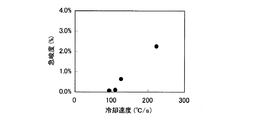
図6は、板厚t=10mm、板幅W=3000mm、通板速度V=0.58m/s、ロールピッチL=750mmとして、冷却速度Cvと耳波形状の急峻度λとの関係を示す図である。冷却速度Cvが小さくなるほど急峻度λは小さくなることが確認された。冷却速度Cvが110℃/s以下の場合、耳波は発生しなかった。 FIG. 6 shows the relationship between the cooling speed Cv and the steepness λ of the spike shape, where the plate thickness t=10 mm, the plate width W=3000 mm, the plate passing speed V=0.58 m/s, and the roll pitch L=750 mm. It is a figure. It was confirmed that the steepness λ decreases as the cooling rate Cv decreases. When the cooling rate Cv was 110° C./s or less, no ear wave was generated.
図7は、板厚t=6mm、ロールピッチL=750mm、冷却速度Cv=300℃/sとして、板幅Wが1500mmと板幅Wが3000mmの場合の鋼板について、通板速度Vと急峻度λとの関係を示す図である。いずれの板幅であっても、通板速度Vが速いほど、急峻度λは小さくなることが確認された。また、板幅Wが1500mmでは、通板速度Vが1.8m/s以上で耳波が発生しなかった。一方、板幅Wが3000mmでは、通板速度Vが3.0m/s以上で耳波が発生しなかった。これらの結果から、同じ通板速度の場合、板幅が大きいほど形状が悪くなることが分かった。 FIG. 7 shows a plate thickness t=6 mm, a roll pitch L=750 mm, a cooling rate Cv=300° C./s, and a sheet passing speed V and steepness for a steel sheet having a sheet width W of 1500 mm and a sheet width W of 3000 mm. It is a figure which shows the relationship with (lambda). It was confirmed that the steepness λ becomes smaller as the sheet passing speed V becomes faster regardless of the plate width. Further, when the plate width W was 1500 mm, the running speed V was 1.8 m/s or more, and no seismic wave was generated. On the other hand, when the plate width W was 3000 mm, the running speed V was 3.0 m/s or more, and no ear wave was generated. From these results, it was found that the shape becomes worse as the plate width becomes larger at the same plate passing speed.
なお、厚鋼板では板厚が厚いほど、冷却時に鋼板表面と鋼板中心において、温度差が生じる。そのため、ここでの冷却速度Cvは、板厚方向の平均温度に対する冷却速度である。 The thicker the steel plate, the greater the difference in temperature between the steel plate surface and the steel plate center during cooling. Therefore, the cooling rate Cv here is a cooling rate with respect to the average temperature in the plate thickness direction.
これらの知見から、座屈変形は、通板速度V、冷却速度Cv、ロールピッチL、板厚t、板幅Wに起因して発生するといえる。そこで本発明者らがさらに検討した結果、下記式(1)で表される通板速度Vを満足すれば、座屈変形が発生せず、歪の少ない鋼板を得られることがわかった。
V>2.21×10⁻⁵×Cv×L3×t−2×(24.2+204.3×(L/W)2)−1・・・(1)
ただし、式(1)において、
V:通板速度(m/s)
Cv:板厚方向の鋼板平均温度に対する冷却速度(℃/s)
L:ロールピッチ(m)
t:板厚(m)
W:板幅(m)
である。
From these findings, it can be said that the buckling deformation occurs due to the plate passing speed V, the cooling speed Cv, the roll pitch L, the plate thickness t, and the plate width W. As a result of further study by the present inventors, it was found that buckling deformation does not occur and a steel plate with less distortion can be obtained if the strip running speed V represented by the following formula (1) is satisfied.
V>2.21×10 −5 ×Cv×L 3 ×t −2 ×(24.2+204.3×(L/W) 2 ) −1 (1)
However, in equation (1),
V: Plate passing speed (m/s)
Cv: Cooling rate (°C/s) with respect to the average temperature of the steel plate in the plate thickness direction
L: Roll pitch (m)
t: plate thickness (m)
W: Board width (m)
Is.
以下、上記式(1)の導出について説明する。 The derivation of the above equation (1) will be described below.
弾性学ハンドブック(中原ら,2001年,朝倉書店,P.264)によれば、座屈限界の圧縮応力は以下のように記載されている。 According to the Elasticity Handbook (Nakahara et al., 2001, Asakura Shoten, P.264), the compressive stress at the buckling limit is described as follows.

σe:座屈限界応力(MPa)
k:座屈係数
E:ヤング率(MPa)
π:円周率
ν:ポアソン比
t:板厚(m)
L:ロールピッチ(m)
W:板幅(m)
m:波数(通常1をとる)
なお、Lは弾性学ハンドブックでは板長さと記載されているが、今回はロールで拘束している系であるため、応力の方向から判断してロールピッチと読み替える。また、座屈係数kに関しては、式(4)は初等解析の一例である。実際は鋼板の拘束状態などが変化するため、この式(4)通りの座屈係数にはならない。そのため、座屈係数kは、式(4)を参考に実態に合うように適宜修正して利用されることが多い。
σ e : Buckling limit stress (MPa)
k: Buckling coefficient E: Young's modulus (MPa)
π: Circumferential ratio ν: Poisson's ratio t: Plate thickness (m)
L: Roll pitch (m)
W: Board width (m)
m: wave number (normally 1)
Although L is described as a plate length in the elasticity handbook, it is a system constrained by rolls this time, so it is read as a roll pitch by judging from the stress direction. Regarding the buckling coefficient k, equation (4) is an example of elementary analysis. In reality, the buckling coefficient does not satisfy the equation (4) because the restraint state of the steel sheet changes. Therefore, the buckling coefficient k is often used by referring to the equation (4) and appropriately correcting it so as to match the actual condition.
図8のように、一部のロール間の鋼板(ロールピッチL間の鋼板)を切り出して考えると、ロール間入側温度およびロール間出側温度から、鋼板の幅方向に及ぼす圧縮応力は以下のように記載できる。 As shown in FIG. 8, when a steel sheet between some rolls (a steel sheet between roll pitches L) is cut out and considered, the compressive stress exerted in the width direction of the steel sheet from the interroll temperature between rolls and the interroll temperature between rolls is as follows. Can be described as follows.
![]()
![]()
σa:幅方向の圧縮応力(MPa)
α:線膨張率(1/℃)
E:ヤング率(MPa)
Tin:ロール間入側温度(℃)
Tout:ロール間出側温度(℃)
ロール間において、一定の冷却速度で冷却されたとすると、上記の式(5)のロール間入側温度Tinおよびロール間出側温度Toutは以下のように記載することができる。
σ a : compressive stress in the width direction (MPa)
α: linear expansion coefficient (1/°C)
E: Young's modulus (MPa)
T in : Temperature between rolls (°C)
T out : Roll-out temperature (°C)
Assuming that the rolls are cooled at a constant cooling rate, the inter-roll temperature T in and the inter-roll temperature T out between the rolls in the above formula (5) can be described as follows.
![]()
![]()
Cv:冷却速度(℃/s)
V:通板速度(m/s)
すなわち、幅方向の圧縮応力σaは次のように記載することができる。
Cv: Cooling rate (°C/s)
V: Plate passing speed (m/s)
That is, the compressive stress σ a in the width direction can be described as follows.
幅方向の圧縮応力σaが、座屈限界応力σeよりも小さい場合は座屈しないことから、式(8)の関係式を満たせば座屈変形はしない。 When the compressive stress σ a in the width direction is smaller than the buckling limit stress σ e , the buckling does not occur, so that the buckling deformation does not occur if the relational expression (8) is satisfied.
式(8)を通板速度Vに対して書き直すと以下のようになる。 The equation (8) is rewritten for the strip speed V as follows.
なお、鋼の場合は、ポアソン比ν及び熱膨張率αは固有値を持つため、定数として考えると、座屈変形しない通板速度Vは以下のように記載できる。(高温域での操業を想定し、ポアソン比ν及び熱膨張率αはそれぞれν=0.3、α=2.0×10⁻⁵で換算) In the case of steel, the Poisson's ratio ν and the coefficient of thermal expansion α have eigenvalues. Therefore, when considered as constants, the striping speed V at which buckling does not occur can be described as follows. (Assuming operation in high temperature range, Poisson's ratio ν and coefficient of thermal expansion α are converted into ν=0.3 and α=2.0×10 −5 , respectively)
座屈係数kは、上記式(10)から導き出される下記式(11)となる。 The buckling coefficient k is given by the following equation (11) derived from the above equation (10).
![]()
![]()
ここで、座屈係数kはプロセス固有の値となるため、種々の実験を実機で行い、座屈係数kを実際に求めた。実際に座屈係数kを求めるべく、実験条件としては、板厚tを5〜15mm、板幅Wを3000〜5000mm、ロールピッチLを500〜750mm、通板速度を0.3〜2.0m/sとした。 Here, since the buckling coefficient k is a value peculiar to the process, various experiments were conducted with an actual machine to actually obtain the buckling coefficient k. In order to actually obtain the buckling coefficient k, as the experimental conditions, the plate thickness t is 5 to 15 mm, the plate width W is 3000 to 5000 mm, the roll pitch L is 500 to 750 mm, and the sheet passing speed is 0.3 to 2.0 m. /S.
一方、実際に座屈する境界の座屈定数kは、上記式(4)から、ロールピッチLと板幅Wの2乗に関係すると考えられる。先に述べたように、座屈係数kは各端部の拘束や変形条件などで式(4)の理論式からずれることがあり、例えばせん断力がある場合は(W/L)項を省略する例も存在する。そこで、今回は(W/L)項を省略した場合で実機にて実際に求めた座屈係数kと、ロールピッチLと板幅Wの2乗との関係をプロットした。その結果を図9に示す。図9において、○は急峻度λが0.5%未満であり、×は急峻度λが0.5%以上であることを示す。図9から、実際に座屈する境界の座屈定数kと急峻度λとの間に相関関係があるといえる。 On the other hand, the buckling constant k of the boundary that actually buckles is considered to be related to the square of the roll pitch L and the strip width W from the above equation (4). As described above, the buckling coefficient k may deviate from the theoretical formula of the formula (4) due to the constraint of each end and the deformation condition. For example, when there is shearing force, the (W/L) term is omitted. There is also an example. Therefore, this time, the relationship between the buckling coefficient k actually found in the actual machine when the (W/L) term was omitted, and the roll pitch L and the square of the strip width W was plotted. The result is shown in FIG. In FIG. 9, ◯ indicates that the steepness λ is less than 0.5%, and x indicates that the steepness λ is 0.5% or more. From FIG. 9, it can be said that there is a correlation between the buckling constant k of the boundary that actually buckles and the steepness λ.
図9の結果から、座屈係数kは、以下の関係で表すことができる。
k=204.3(L/W)2+24.2・・・(12)
式(10)および式(12)を組み合わせることで、座屈しない通板速度Vは、下記式(1)で表すことができる。
V>2.21×10⁻⁵×Cv×L3×t−2×(24.2+204.3×(L/W)2)−1・・・(1)
ただし、式(1)において、
V:通板速度(m/s)
Cv:板厚方向の鋼板平均温度に対する冷却速度(℃/s)
L:ロールピッチ(m)
t:板厚(m)
W:板幅(m)
である。
From the result of FIG. 9, the buckling coefficient k can be expressed by the following relationship.
k=204.3 (L/W) 2 +24.2 (12)
By combining the equations (10) and (12), the buckling-free threading speed V can be expressed by the following equation (1).
V>2.21×10 −5 ×Cv×L 3 ×t −2 ×(24.2+204.3×(L/W) 2 ) −1 (1)
However, in equation (1),
V: Plate passing speed (m/s)
Cv: Cooling rate (°C/s) with respect to the average temperature of the steel plate in the plate thickness direction
L: Roll pitch (m)
t: plate thickness (m)
W: Board width (m)
Is.
なお、ロールピッチLは機械構成から来るパラメータであるため、機械設置後は変更できないパラメータである。また、板厚t、板幅Wや冷却速度Cvは、商品の特性を決定するのに関連するパラメータであり、これも単純に変更することができない。そこで、操業上、適宜変更が可能なパラメータである通板速度Vに着目して式(1)を整理している。 Since the roll pitch L is a parameter that depends on the machine configuration, it is a parameter that cannot be changed after the machine is installed. Further, the plate thickness t, the plate width W, and the cooling rate Cv are parameters related to determining the characteristics of the product, and these cannot be simply changed. Therefore, the formula (1) is organized by focusing on the strip passing speed V, which is a parameter that can be appropriately changed in operation.
上記式(1)から、座屈変形は板厚tが薄いほど、ロールピッチLが広いほど、冷却速度Cvが速いほど、板幅が広い場合、座屈変形させないためには早い通板速度Vで冷却する必要があることがわかる。ここで、ロールピッチL、冷却速度Cv、通板速度Vは冷却設備固有の値であり、板厚t、板幅Wは製品により決まる。一方、冷却速度Cvは冷却装置の冷却水の流量、通板速度Vはテーブルロールの回転数であり、それぞれ変更可能である。そこで、設計段階で予め製造品種の範囲に応じて、冷却装置のロールピッチを可能な限り短く設計しておき(たとえば500mmピッチ)、テーブルロールの回転数はなるべく早く回転するようにし(たとえば2m/s以上まで)、冷却水の流量の調整範囲も広くするように設計するのがよい。また、既存の設備を活用するなどのロールピッチLを短縮できない場合は、冷却水の流量の調整範囲を広くして、少ない流量での冷却を可能とすることで冷却速度Cvを遅くするのが有効である(たとえば、板厚10mmで100℃/s以下)。熱延鋼帯を製造するホットストリップミルや厚鋼板のオンライン制御冷却では、板厚10mmの厚みでおおよそ2.5m/s程度の通板速度となり、比較的速度が早いため、このような座屈変形は発生しにくい。一方、厚鋼板のオフライン熱処理時の冷却では、加熱炉の抽出速度と連動して水冷するため、1.0m/s程度の通板速度となるため、本発明で説明したような座屈変形が発生しやすい。 From the above formula (1), when the plate thickness t is thinner, the roll pitch L is wider, the cooling rate Cv is faster, and the plate width is wider, the buckling deformation is faster in order to prevent buckling deformation. It turns out that it is necessary to cool with. Here, the roll pitch L, the cooling speed Cv, and the plate passing speed V are values unique to the cooling equipment, and the plate thickness t and the plate width W are determined by the product. On the other hand, the cooling speed Cv is the flow rate of the cooling water of the cooling device, and the plate passing speed V is the rotation speed of the table roll, which can be changed. Therefore, in the design stage, the roll pitch of the cooling device is designed in advance as short as possible (for example, 500 mm pitch) in accordance with the range of manufactured products, and the rotation speed of the table roll is set to rotate as fast as possible (for example, 2 m/m). (up to s or more), it is preferable to design so as to widen the adjustment range of the flow rate of cooling water. Further, when the roll pitch L cannot be shortened by utilizing the existing equipment, the cooling speed Cv is slowed down by widening the adjustment range of the cooling water flow rate to enable cooling with a small flow rate. Effective (for example, 100° C./s or less at a plate thickness of 10 mm). In hot strip mills for producing hot-rolled steel strips and on-line controlled cooling of thick steel plates, a plate passing speed of about 2.5 m/s is achieved at a plate thickness of 10 mm, and the speed is relatively high. Deformation is unlikely to occur. On the other hand, in the cooling of the thick steel plate during the off-line heat treatment, since the water cooling is performed in conjunction with the extraction speed of the heating furnace, the plate passing speed is about 1.0 m/s, so that the buckling deformation as described in the present invention occurs. Likely to happen.
以上より、本発明では、上記式(1)を満足する通板速度Vで鋼板を冷却させることにより、冷却歪の少ない鋼板の製造が可能となる。本発明では、板厚が薄く且つ板幅が広い鋼板に関して効果が発現する。特に板厚が10mm以下および/または板幅3000mm以上の厚鋼板の冷却に好適であり、厚鋼板のオフライン熱処理に適用することができる。 As described above, according to the present invention, it is possible to manufacture a steel sheet with a small cooling strain by cooling the steel sheet at the sheet passing speed V satisfying the above formula (1). In the present invention, the effect is exerted on a steel plate having a small plate thickness and a wide plate width. In particular, it is suitable for cooling a thick steel plate having a plate thickness of 10 mm or less and/or a plate width of 3000 mm or more, and can be applied to off-line heat treatment of a thick steel plate.
図1に示す製造設備を用いて、鋼板を冷却させた。ここで、加熱炉10における加熱温度は930℃とし、板厚は座屈変形が発生しやすい板厚5mm、10mm、12mmとした。冷却ノズル3はフラットスプレーを幅方向に複数並べたものを用いた。冷却水量は変更可能であり、最大水量を噴射した場合の板厚5mmの厚鋼板の冷却速度は400℃/s、最小流量を噴射した時の冷却速度は100℃/sである。なお、冷却水量を一定として、板厚だけ変更して冷却した場合、冷却速度は板厚に逆比例する。よって、板厚10mmの場合の最大冷却速度は200℃/s、最小冷却速度は50℃/sとなる。また、ロールピッチLは各条件毎に変更した。
The steel sheet was cooled using the manufacturing equipment shown in FIG. Here, the heating temperature in the
鋼板形状は急峻度λで判断した。急峻度λが0.5%未満を鋼板形状がフラットであると判断し、一方、急峻度λが0.5%以上を鋼板形状が座屈変形していると判断した。なお、急峻度λを求めるに際し、δ/Pは鋼板両端部に発生した全ての耳波の平均値から算出した。 The shape of the steel sheet was judged by the steepness λ. When the steepness λ was less than 0.5%, it was determined that the steel sheet shape was flat, while when the steepness λ was 0.5% or more, it was determined that the steel sheet shape was buckled. In obtaining the steepness λ, δ/P was calculated from the average value of all the ear waves generated at both ends of the steel sheet.
結果を表1に示す。 The results are shown in Table 1.
本発明例は、式(1)で求められる通板速度Vよりも速い通板速度にて冷却している。いずれの本発明例も座屈変形は発生せずフラットな形状となった。一方、比較例はいずれも、式(1)で求められる通板速度Vよりも遅い通板速度にて冷却している。いずれの比較例もすべての条件で座屈変形が発生した。その結果、比較例の全ての鋼板は、冷却後にローラー矯正機で形状修正を行って出荷した。本発明例の全ての鋼板は、再矯正せずにそのまま出荷が可能であった。 In the example of the present invention, cooling is performed at a plate passing speed higher than the plate passing speed V obtained by the formula (1). In each of the examples of the present invention, buckling deformation did not occur and the shape was flat. On the other hand, in all of the comparative examples, cooling is performed at a strip passing speed lower than the strip passing speed V obtained by the equation (1). In all comparative examples, buckling deformation occurred under all conditions. As a result, all the steel sheets of the comparative example were shipped after being subjected to shape correction by a roller straightening machine after cooling. All the steel sheets of the examples of the present invention could be shipped as they were without re-correction.
なお、一般的な厚鋼板のオフライン熱処理装置の搬送速度制御は、加熱炉の駆動機構に影響され、搬送速度はおよそ0.02〜0.5m/s程度の速度制御が可能なものが多い。実施例の結果からもわかるように、特に板厚12mmの実験条件では、冷却速度が速くても、本発明の式(1)で求められる通板速度、すなわち搬送速度は、実機の搬送速度制御範囲に入るため、形状調整は容易である。更に板幅の狭い鋼板も、同じく本発明の式(1)で求められる通板速度、すなわち搬送速度が実機の搬送速度制御範囲に入るため、形状調整は容易である。一方、特に本発明の冷却速度制御やロールピッチの変更などは、板厚10mm以下、および/または、板幅3000mm以上の鋼板においては、本発明の式(1)で求められる通板速度、すなわち搬送速度が実機の搬送速度制御範囲外となることがある。このため、板厚10mm以下、および/または、板幅3000mm以上の鋼板に対して本発明を実施する場合には、冷却速度制御やロールピッチの変更などが必要であることが分かる。また、特に板厚5mmと薄く且つ板幅5000mmの条件では、ロールピッチを500mmと狭くするのに加えて、通板速度を2.0m/sと一般的な設備より若干早く制御することで、座屈変形が防止できることがわかる。 In addition, the transporting speed control of a general off-line heat treatment apparatus for thick steel plates is affected by the driving mechanism of the heating furnace, and the transporting speed is often about 0.02 to 0.5 m/s. As can be seen from the results of the examples, particularly under the experimental condition of the plate thickness of 12 mm, even if the cooling rate is high, the plate passing speed obtained by the formula (1) of the present invention, that is, the carrying speed is the carrying speed control of the actual machine. Shape adjustment is easy because it falls within the range. Further, the shape of a steel sheet having a narrow width can be easily adjusted because the sheet passing speed obtained by the formula (1) of the present invention, that is, the conveying speed falls within the conveying speed control range of the actual machine. On the other hand, particularly in the cooling rate control and roll pitch change of the present invention, in the case of a steel plate having a plate thickness of 10 mm or less and/or a plate width of 3000 mm or more, the strip running speed obtained by the formula (1) of the present invention, that is, The transport speed may be outside the transport speed control range of the actual machine. Therefore, when the present invention is applied to a steel plate having a plate thickness of 10 mm or less and/or a plate width of 3000 mm or more, it is necessary to control the cooling rate and change the roll pitch. Further, in particular, under the condition that the plate thickness is as thin as 5 mm and the plate width is 5000 mm, in addition to narrowing the roll pitch to 500 mm, by controlling the passing speed to 2.0 m/s, which is slightly faster than general equipment, It can be seen that buckling deformation can be prevented.
1 鋼板
2 ロール
2−0 ロール
2−1 ロール
2−i ロール
2−n ロール
3 冷却ノズル
10 加熱炉(ハースロール加熱炉)
δ 波高さ
P 波ピッチ
1
δ Wave height P Wave pitch
Claims (7)
下記式(1)を満足する通板速度Vで冷却することを特徴とする鋼板の冷却方法。
V>2.21×10⁻⁵×Cv×L3×t−2×(24.2+204.3×(L/W)2)−1・・・(1)
ただし、式(1)において、
V:通板速度(m/s)
Cv:板厚方向の鋼板平均温度に対する冷却速度(℃/s)
L:ロールピッチ(m)
t:板厚(m)
W:板幅(m)
である。 The steel plate is conveyed while being constrained by a plurality of rolls arranged at a predetermined pitch in the steel plate conveyance direction, and cooling water is sprayed onto the upper and lower surfaces of the steel plate by a cooling nozzle arranged between the plurality of rolls to cool the steel plate. In the method of cooling the steel sheet,
A method for cooling a steel sheet, comprising cooling at a sheet passing speed V satisfying the following formula (1).
V>2.21×10 −5 ×Cv×L 3 ×t −2 ×(24.2+204.3×(L/W) 2 ) −1 (1)
However, in equation (1),
V: Plate passing speed (m/s)
Cv: Cooling rate (°C/s) with respect to the average temperature of the steel plate in the plate thickness direction
L: Roll pitch (m)
t: plate thickness (m)
W: Board width (m)
Is.
複数のロール間に配置されて、鋼板の上下面に冷却水を噴射して鋼板を冷却する冷却ノズルと、
下記式(1)を満足するように通板速度Vを制御する制御機構と
を備えることを特徴とする鋼板の冷却装置。
V>2.21×10⁻⁵×Cv×L3×t−2×(24.2+204.3×(L/W)2)−1・・・(1)
ただし、式(1)において、
V:通板速度(m/s)
Cv:板厚方向の鋼板平均温度に対する冷却速度(℃/s)
L:ロールピッチ(m)
t:板厚(m)
W:板幅(m)
である。 A plurality of rolls arranged at a predetermined pitch in the steel plate transport direction to constrain and transport the steel plate,
A cooling nozzle arranged between a plurality of rolls to cool the steel sheet by spraying cooling water on the upper and lower surfaces of the steel sheet,
A cooling mechanism for a steel sheet, comprising: a control mechanism that controls the strip passing speed V so as to satisfy the following formula (1).
V>2.21×10 −5 ×Cv×L 3 ×t −2 ×(24.2+204.3×(L/W) 2 ) −1 (1)
However, in equation (1),
V: Plate passing speed (m/s)
Cv: Cooling rate (°C/s) with respect to the average temperature of the steel plate in the plate thickness direction
L: Roll pitch (m)
t: plate thickness (m)
W: Board width (m)
Is.
Priority Applications (5)
| Application Number | Priority Date | Filing Date | Title |
|---|---|---|---|
| JP2017038973A JP6720894B2 (en) | 2017-03-02 | 2017-03-02 | Steel sheet cooling method, steel sheet cooling device, and steel sheet manufacturing method |
| EP18760481.4A EP3560616B1 (en) | 2017-03-02 | 2018-03-01 | Method for cooling steel sheet and method for manufacturing steel sheet |
| PCT/JP2018/007743 WO2018159749A1 (en) | 2017-03-02 | 2018-03-01 | Method for cooling steel sheet, cooling device for steel sheet and method for manufacturing steel sheet |
| CN201880015172.2A CN110366456B (en) | 2017-03-02 | 2018-03-01 | Method and apparatus for cooling steel sheet, and method for manufacturing steel sheet |
| KR1020197025297A KR102303872B1 (en) | 2017-03-02 | 2018-03-01 | A method for cooling a steel sheet, a cooling device for a steel sheet, and a method for manufacturing a steel sheet |
Applications Claiming Priority (1)
| Application Number | Priority Date | Filing Date | Title |
|---|---|---|---|
| JP2017038973A JP6720894B2 (en) | 2017-03-02 | 2017-03-02 | Steel sheet cooling method, steel sheet cooling device, and steel sheet manufacturing method |
Publications (3)
| Publication Number | Publication Date |
|---|---|
| JP2018144050A JP2018144050A (en) | 2018-09-20 |
| JP2018144050A5 JP2018144050A5 (en) | 2018-12-06 |
| JP6720894B2 true JP6720894B2 (en) | 2020-07-08 |
Family
ID=63371165
Family Applications (1)
| Application Number | Title | Priority Date | Filing Date |
|---|---|---|---|
| JP2017038973A Active JP6720894B2 (en) | 2017-03-02 | 2017-03-02 | Steel sheet cooling method, steel sheet cooling device, and steel sheet manufacturing method |
Country Status (5)
| Country | Link |
|---|---|
| EP (1) | EP3560616B1 (en) |
| JP (1) | JP6720894B2 (en) |
| KR (1) | KR102303872B1 (en) |
| CN (1) | CN110366456B (en) |
| WO (1) | WO2018159749A1 (en) |
Families Citing this family (6)
| Publication number | Priority date | Publication date | Assignee | Title |
|---|---|---|---|---|
| CN115786683A (en) * | 2017-10-31 | 2023-03-14 | 杰富意钢铁株式会社 | Manufacturing equipment and manufacturing method of thick steel plate |
| JP7076323B2 (en) * | 2018-07-31 | 2022-05-27 | 株式会社ユニバーサルエンターテインメント | Pachinko machine |
| CN109794506B (en) * | 2019-04-04 | 2023-10-24 | 哈尔滨工业大学(威海) | Roll forming device and method for hot formed steel plate |
| CN114728320A (en) * | 2019-11-25 | 2022-07-08 | 杰富意钢铁株式会社 | Steel plate manufacturing equipment and manufacturing method |
| CN117083133A (en) | 2021-02-18 | 2023-11-17 | 杰富意钢铁株式会社 | Shape prediction method, shape control method, manufacturing method, shape prediction model generation method, and manufacturing apparatus for steel plate |
| CN114130834B (en) * | 2021-11-30 | 2023-08-22 | 宝武集团鄂城钢铁有限公司 | Production method for precisely controlling thickness range of thin steel plate by adopting single-frame rolling mill |
Family Cites Families (11)
| Publication number | Priority date | Publication date | Assignee | Title |
|---|---|---|---|---|
| JPS5193769A (en) * | 1975-02-15 | 1976-08-17 | ||
| JPH0222424A (en) * | 1988-07-08 | 1990-01-25 | Sumitomo Metal Ind Ltd | Roll cooling method for hoop |
| JPH0763750B2 (en) * | 1988-12-28 | 1995-07-12 | 新日本製鐵株式会社 | Cooling control device for hot rolled steel sheet |
| JPH0866713A (en) * | 1994-08-30 | 1996-03-12 | Kawasaki Steel Corp | Cooling control method for rolled stock |
| JP2843273B2 (en) | 1995-01-05 | 1999-01-06 | 株式会社神戸製鋼所 | Hot rolled steel sheet shape prediction method |
| JP3925789B2 (en) | 2002-05-17 | 2007-06-06 | Jfeスチール株式会社 | High temperature steel sheet cooling method, high temperature steel sheet cooling device, and steel sheet manufacturing method |
| JP3978141B2 (en) * | 2003-01-16 | 2007-09-19 | 新日本製鐵株式会社 | Thick steel plate cooling method and cooling device |
| KR100935490B1 (en) * | 2005-06-23 | 2010-01-06 | 신닛뽄세이테쯔 카부시키카이샤 | Cooling device for thick steel plate |
| JP4586791B2 (en) * | 2006-10-30 | 2010-11-24 | Jfeスチール株式会社 | Cooling method for hot-rolled steel strip |
| FI20070622L (en) * | 2007-08-17 | 2009-04-15 | Outokumpu Oy | Method and device for checking evenness during cooling of a strip made of stainless steel |
| JP5626275B2 (en) * | 2011-07-27 | 2014-11-19 | 新日鐵住金株式会社 | Method for cooling hot-rolled steel sheet |
-
2017
- 2017-03-02 JP JP2017038973A patent/JP6720894B2/en active Active
-
2018
- 2018-03-01 KR KR1020197025297A patent/KR102303872B1/en active IP Right Grant
- 2018-03-01 EP EP18760481.4A patent/EP3560616B1/en active Active
- 2018-03-01 CN CN201880015172.2A patent/CN110366456B/en active Active
- 2018-03-01 WO PCT/JP2018/007743 patent/WO2018159749A1/en unknown
Also Published As
| Publication number | Publication date |
|---|---|
| KR102303872B1 (en) | 2021-09-17 |
| JP2018144050A (en) | 2018-09-20 |
| WO2018159749A1 (en) | 2018-09-07 |
| CN110366456A (en) | 2019-10-22 |
| CN110366456B (en) | 2021-08-31 |
| EP3560616B1 (en) | 2023-01-25 |
| EP3560616A4 (en) | 2020-01-15 |
| EP3560616A1 (en) | 2019-10-30 |
| KR20190112085A (en) | 2019-10-02 |
Similar Documents
| Publication | Publication Date | Title |
|---|---|---|
| JP6720894B2 (en) | Steel sheet cooling method, steel sheet cooling device, and steel sheet manufacturing method | |
| JP6521193B1 (en) | Steel plate manufacturing equipment and steel plate manufacturing method | |
| WO2011042934A1 (en) | Cooling apparatus and cooling method for hot rolling | |
| JP2008238241A (en) | Manufacturing method of aluminum metal sheet | |
| JP2020196049A (en) | Manufacturing method for hat-shaped steel sheet pile | |
| JP4289480B2 (en) | Straightening method to obtain steel plate with good shape with little variation in residual stress | |
| JP6897609B2 (en) | Hot rolling equipment and hot-rolled steel sheet manufacturing method | |
| JP2005279703A (en) | Method and equipment for manufacturing steel sheet | |
| JP6172108B2 (en) | Hot rolled steel sheet rolling method | |
| JP6569691B2 (en) | Manufacturing method of unequal side unequal thickness angle steel | |
| JP7173377B2 (en) | Steel plate manufacturing equipment and manufacturing method | |
| JP2008231476A (en) | Method for producing steel sheet | |
| JP5854177B1 (en) | Hot rolling method for high carbon steel | |
| JP6447836B2 (en) | Hot-rolled steel strip manufacturing method and hot-rolled steel strip manufacturing equipment | |
| JP7501465B2 (en) | Method for determining twist under width reduction of hot slab, method for width reduction of hot slab, and method for manufacturing hot rolled steel sheet | |
| JP6172110B2 (en) | Hot rolled steel sheet rolling method | |
| JP4305156B2 (en) | Heat treatment method for steel sheet | |
| JP2005125351A (en) | Steel plate producing line and steel plate producing method | |
| JP5673370B2 (en) | Method for cooling hot-rolled steel sheet | |
| JP2005074480A (en) | Facility for producing hot-rolled steel plate, and its production method | |
| KR100711385B1 (en) | A method for diminishing slit camber of stripping plate | |
| JP2023158774A (en) | Width press device and slab width press method | |
| JP6627730B2 (en) | Hot slab width reduction device, hot slab width reduction method, and hot rolled steel sheet manufacturing method | |
| JP6168006B2 (en) | Hearth roll equipment for continuous annealing furnace and control method thereof | |
| JPS60115306A (en) | Thick plate manufacturing installation |
Legal Events
| Date | Code | Title | Description |
|---|---|---|---|
| RD03 | Notification of appointment of power of attorney |
Free format text: JAPANESE INTERMEDIATE CODE: A7423 Effective date: 20180502 |
|
| RD04 | Notification of resignation of power of attorney |
Free format text: JAPANESE INTERMEDIATE CODE: A7424 Effective date: 20180509 |
|
| A621 | Written request for application examination |
Free format text: JAPANESE INTERMEDIATE CODE: A621 Effective date: 20181024 |
|
| A521 | Request for written amendment filed |
Free format text: JAPANESE INTERMEDIATE CODE: A523 Effective date: 20181026 |
|
| RD04 | Notification of resignation of power of attorney |
Free format text: JAPANESE INTERMEDIATE CODE: A7424 Effective date: 20190327 |
|
| A131 | Notification of reasons for refusal |
Free format text: JAPANESE INTERMEDIATE CODE: A131 Effective date: 20191126 |
|
| TRDD | Decision of grant or rejection written | ||
| A01 | Written decision to grant a patent or to grant a registration (utility model) |
Free format text: JAPANESE INTERMEDIATE CODE: A01 Effective date: 20200519 |
|
| A61 | First payment of annual fees (during grant procedure) |
Free format text: JAPANESE INTERMEDIATE CODE: A61 Effective date: 20200601 |
|
| R150 | Certificate of patent or registration of utility model |
Ref document number: 6720894 Country of ref document: JP Free format text: JAPANESE INTERMEDIATE CODE: R150 |
|
| R250 | Receipt of annual fees |
Free format text: JAPANESE INTERMEDIATE CODE: R250 |
|
| R250 | Receipt of annual fees |
Free format text: JAPANESE INTERMEDIATE CODE: R250 |