JP6718256B2 - Image processing device, imaging device, control method thereof, and program - Google Patents
Image processing device, imaging device, control method thereof, and program Download PDFInfo
- Publication number
- JP6718256B2 JP6718256B2 JP2016036313A JP2016036313A JP6718256B2 JP 6718256 B2 JP6718256 B2 JP 6718256B2 JP 2016036313 A JP2016036313 A JP 2016036313A JP 2016036313 A JP2016036313 A JP 2016036313A JP 6718256 B2 JP6718256 B2 JP 6718256B2
- Authority
- JP
- Japan
- Prior art keywords
- light source
- subject
- image
- virtual light
- state
- Prior art date
- Legal status (The legal status is an assumption and is not a legal conclusion. Google has not performed a legal analysis and makes no representation as to the accuracy of the status listed.)
- Active
Links
- 238000012545 processing Methods 0.000 title claims description 99
- 238000000034 method Methods 0.000 title claims description 40
- 238000003384 imaging method Methods 0.000 title claims description 15
- 230000008859 change Effects 0.000 claims description 26
- 238000006243 chemical reaction Methods 0.000 description 21
- 230000008569 process Effects 0.000 description 21
- 238000004364 calculation method Methods 0.000 description 18
- 238000005286 illumination Methods 0.000 description 9
- 238000001514 detection method Methods 0.000 description 7
- 238000012937 correction Methods 0.000 description 5
- 238000010586 diagram Methods 0.000 description 5
- 230000006870 function Effects 0.000 description 5
- 230000007274 generation of a signal involved in cell-cell signaling Effects 0.000 description 5
- 229920006395 saturated elastomer Polymers 0.000 description 4
- 201000005569 Gout Diseases 0.000 description 3
- 230000003321 amplification Effects 0.000 description 2
- 238000005259 measurement Methods 0.000 description 2
- 238000003199 nucleic acid amplification method Methods 0.000 description 2
- 230000003287 optical effect Effects 0.000 description 2
- 239000004065 semiconductor Substances 0.000 description 2
- 238000013528 artificial neural network Methods 0.000 description 1
- 230000008901 benefit Effects 0.000 description 1
- 238000004891 communication Methods 0.000 description 1
- 230000000694 effects Effects 0.000 description 1
- 238000005516 engineering process Methods 0.000 description 1
- 239000011159 matrix material Substances 0.000 description 1
- 230000007246 mechanism Effects 0.000 description 1
- 238000012544 monitoring process Methods 0.000 description 1
Images


Classifications
-
- H—ELECTRICITY
- H04—ELECTRIC COMMUNICATION TECHNIQUE
- H04N—PICTORIAL COMMUNICATION, e.g. TELEVISION
- H04N23/00—Cameras or camera modules comprising electronic image sensors; Control thereof
- H04N23/70—Circuitry for compensating brightness variation in the scene
- H04N23/74—Circuitry for compensating brightness variation in the scene by influencing the scene brightness using illuminating means
-
- H—ELECTRICITY
- H04—ELECTRIC COMMUNICATION TECHNIQUE
- H04N—PICTORIAL COMMUNICATION, e.g. TELEVISION
- H04N23/00—Cameras or camera modules comprising electronic image sensors; Control thereof
- H04N23/70—Circuitry for compensating brightness variation in the scene
- H04N23/76—Circuitry for compensating brightness variation in the scene by influencing the image signals
-
- H—ELECTRICITY
- H04—ELECTRIC COMMUNICATION TECHNIQUE
- H04N—PICTORIAL COMMUNICATION, e.g. TELEVISION
- H04N23/00—Cameras or camera modules comprising electronic image sensors; Control thereof
- H04N23/80—Camera processing pipelines; Components thereof
Landscapes
- Engineering & Computer Science (AREA)
- Multimedia (AREA)
- Signal Processing (AREA)
- Studio Devices (AREA)
- Stroboscope Apparatuses (AREA)
Description
本発明は、画像処理装置、撮像装置およびそれらの制御方法ならびにプログラムに関する。 The present invention relates to an image processing device, an imaging device, a control method thereof, and a program.
一般に、被写体を撮影する際に光源の光量が不足する場合、撮影した画像が暗くなる。このため、暗くなる画像をより明るくするために、例えばストロボ等の照明装置を用いて被写体に光を照射し、十分な光量を確保したうえで撮影する方法が知られている。 Generally, when the amount of light from a light source is insufficient when photographing a subject, the photographed image becomes dark. Therefore, in order to make an image that becomes darker brighter, a method is known in which an illumination device such as a strobe is used to irradiate a subject with light, and a sufficient amount of light is secured before shooting.
しかし、照明装置から被写体までの距離が被写体ごとに異なる場合、被写体ごとに照射される光量が異なるため、被写体によっては照射される光量が適切でない場合がある。例えば、主被写体に照射される光量が適切となるように照明装置から光を照射する場合、主被写体より照明装置に近い被写体では光量が過剰となり白飛びが発生する可能性がある。一方、主被写体より照明装置から遠い被写体では光量が不足し黒潰れが発生する可能性がある。 However, when the distance from the illumination device to the subject is different for each subject, the amount of light emitted is different for each subject, and therefore the amount of light emitted may not be appropriate for some subjects. For example, when light is emitted from the illumination device so that the main subject is irradiated with an appropriate amount of light, the amount of light may be excessive in a subject closer to the illumination device than the main subject, and whiteout may occur. On the other hand, a subject farther from the illumination device than the main subject may have insufficient light quantity and black crushing may occur.
このような課題に対して、特許文献1は、照明装置からの距離が異なる被写体の明るさを調整するため、照明装置から被写体までの距離情報に応じて被写体に異なるゲインをかけることにより、明るさを調整する技術を提案している。 In order to solve such a problem, Patent Literature 1 adjusts the brightness of a subject whose distance from the illumination device is different, and therefore, by applying different gains to the subject according to the distance information from the illumination device to the subject, We propose a technology to adjust the height.
しかしながら、特許文献1で提案された技術では、画像処理によってゲインをかける(すなわち信号を増幅する)ためノイズも増幅されてしまう。また、光源の特性が考慮されていないため、被写体の明るさの差が軽減するだけで照明装置から照射される光による反射成分や光源色を再現することができず、結果的に不自然な画像となる場合がある。 However, in the technique proposed in Patent Document 1, noise is amplified because gain is applied (that is, signal is amplified) by image processing. In addition, since the characteristics of the light source are not taken into consideration, it is not possible to reproduce the reflection component and the light source color due to the light emitted from the lighting device only by reducing the difference in brightness of the subject, resulting in unnaturalness. It may be an image.
本発明は、上述の従来技術の問題点に鑑みてなされたものである。すなわち、発光させる光源からの距離が異なる複数の被写体を撮影した画像に、光源の特性を反映した陰影の調整を行うことが可能な画像処理装置、撮像装置およびそれらの制御方法ならびにプログラムを提供することを目的とする。 The present invention has been made in view of the above-mentioned problems of the conventional art. That is, the present invention provides an image processing device, an imaging device, a control method therefor, and a program capable of adjusting a shadow reflecting the characteristics of a light source in an image obtained by photographing a plurality of subjects having different distances from a light source for emitting light. The purpose is to
この課題を解決するため、例えば本発明の画像処理装置は以下の構成を備える。すなわち、所定の光源の発光を伴って撮影された画像を取得する取得手段と、所定の光源の特性に基づいて、画像に適用する仮想光源を設定する設定手段と、仮想光源によって画像に含まれる複数の被写体の少なくともいずれかの陰影状態を変更した画像を生成する生成手段と、を備え、設定手段は、画像に含まれる、第1の被写体と第2の被写体とが所定の光源から異なる距離に存在する場合に、所定の光源による第1の被写体における陰影状態の変化と所定の光源による第2の被写体における陰影状態の変化との差を低減するように、仮想光源を設定し、更に、設定手段は、第1の被写体における仮想光源による陰影状態の変化が差を低減するように、仮想光源を設定し、第1の被写体における仮想光源による陰影状態の変化は、第1の被写体における仮想光源の反射成分であり、生成手段は、第1の被写体の陰影状態を変更した画像を生成する、ことを特徴とする。
In order to solve this problem, for example, the image processing apparatus of the present invention has the following configuration. That is, an acquisition unit that acquires an image captured with emission of a predetermined light source, a setting unit that sets a virtual light source to be applied to the image based on the characteristics of the predetermined light source, and a virtual light source that is included in the image. And a setting unit configured to generate an image in which at least one of the plurality of subjects has a shaded state changed, wherein the setting unit includes distances at which the first subject and the second subject included in the image are different from a predetermined light source. the when present, so as to reduce the difference between the change in the shading state in the second object according to a predetermined first change and a predetermined light source shading state in the subject by the light source, set the virtual light source, further, The setting means sets the virtual light source so that the change in the shadow state due to the virtual light source in the first subject reduces the difference, and the change in the shadow state due to the virtual light source in the first subject is virtual in the first subject. It is a reflection component of the light source, and the generation means generates an image in which the shaded state of the first subject is changed .
本発明によれば、発光させる光源からの距離が異なる複数の被写体を撮影した画像に、光源の特性を反映した陰影の調整を行うことが可能になる。 ADVANTAGE OF THE INVENTION According to this invention, it becomes possible to adjust the shadow which reflected the characteristic of a light source in the image which image|photographed several to-be-photographed subjects from which the distance from the light source to light-emit differs.
(実施形態1)
以下、本発明の例示的な実施形態について、図面を参照して詳細に説明する。なお、以下では画像処理装置の一例として、撮像可能な任意のデジタルカメラに本発明を適用した例を説明する。しかし、本発明は、デジタルカメラに限らず、撮像された画像を取得してリライティング処理を行うことが可能な任意の機器にも適用可能である。これらの機器には、例えば携帯電話機、ゲーム機、タブレット端末、パーソナルコンピュータ、時計型や眼鏡型の情報端末、監視システム、医療機器などが含まれてよい。
(Embodiment 1)
Hereinafter, exemplary embodiments of the present invention will be described in detail with reference to the drawings. An example in which the present invention is applied to an arbitrary digital camera capable of capturing an image will be described below as an example of the image processing apparatus. However, the present invention is not limited to a digital camera, and can be applied to any device capable of acquiring a captured image and performing relighting processing. These devices may include, for example, a mobile phone, a game machine, a tablet terminal, a personal computer, a watch-type or eyeglass-type information terminal, a monitoring system, a medical device, and the like.
(デジタルカメラ100の構成)
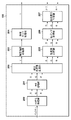
図1は、本実施形態の画像処理装置の一例としてデジタルカメラ100の機能構成例を示すブロック図である。なお、図1に示す機能ブロックの1つ以上は、ASICやプログラマブルロジックアレイ(PLA)などのハードウェアによって実現されてもよいし、CPUやMPU等のプログラマブルプロセッサがソフトウェアを実行することによって実現されてもよい。また、ソフトウェアとハードウェアの組み合わせによって実現されてもよい。従って、以下の説明において、異なる機能ブロックが動作主体として記載されている場合であっても、同じハードウェアが主体として実現されうる。
(Configuration of digital camera 100)
FIG. 1 is a block diagram showing a functional configuration example of a
レンズ群101は、フォーカスレンズやズームレンズを含むレンズ群である。シャッター102は絞り機能を備え、レンズ群101と撮像部103との間に設けられている。撮像部103は、レンズ群101によって撮像面に形成される光学像を2次元状に配列された画素で光電変換し、画素単位の電気信号に出力する撮像素子を有する。撮像素子は、CCDイメージセンサやCMOSイメージセンサであってよい。A/D変換部104は、撮像部103が出力するアナログ信号をデジタル信号(画像データ)に変換する。
The
画像処理部105は、A/D変換部104から出力される画像データに対し、後述する各種画像処理を行う。画像メモリ106は揮発性の半導体メモリを含み、A/D変換部104や画像処理部105から出力された画像データを一時的に記憶する。
The
メモリ制御部107は、画像処理部105や顔検出部113による画像メモリ106の読み書きを制御する。D/A変換部108は、メモリ制御部107から読み出したデジタルをアナログ信号に変換する回路又はモジュールを含む。表示部109は、LCDや有機ELディスプレイ等の表示装置を含み、デジタルカメラ100を操作するための各種GUI、ライブビュー画像、又は記録媒体112から読み出して再生される画像などを表示する。
The
コーデック部110は、画像メモリ106に記憶されている画像データを記録媒体に記録するために予め定められた方法で符号化したり、画像ファイルに含まれる符号化画像データを例えば表示のために復号したりする。インタフェース(I/F)111は、例えば半導体メモリカードやカード型ハードディスクなどの着脱可能な記録媒体112を挿抜する機構を備え、デジタルカメラ100と機械的および電気的に接続する。
The
システム制御部50は、例えばCPUやMPUなどのプロセッサを含み、不揮発性メモリ121等に記録されたプログラムをシステムメモリ122に展開、実行して必要なブロックや回路を制御することにより、デジタルカメラ100の機能を実現する。
The
顔検出部113は、撮影された画像に含まれる顔領域を検出し、検出された顔領域のそれぞれについて、位置、大きさ、信頼度などの顔情報を求める。なお、顔検出部113はニューラルネットワークに代表される学習を用いた手法や、目、鼻、口などの特徴部位を、画像領域からテンプレートマッチングにより探索し類似度が高い領域を顔とみなす手法など、任意の方法を用いることができる。
The
リライティング処理部114は、撮影された画像データに対して後述するリライティング処理を行って被写体の陰影状態を変更した画像を出力する。操作部120は、ユーザがデジタルカメラ100に対する各種の指示を入力するためのボタンやスイッチなどの入力デバイスを含む。表示部109がタッチディスプレイである場合、タッチパネルは操作部120に含まれる。また、音声入力や視線入力など、非接触で指示を入力するタイプの入力デバイスが操作部120に含まれてもよい。
The
不揮発性メモリ121は、電気的に消去・記録可能な、例えばEEPROM等であってよい。不揮発性メモリ121は、例えば各種の設定値、GUIデータを記録するほか、システム制御部50がMPUやCPUである場合、システム制御部50が実行するためのプログラムを記録する。システムメモリ122は、システム制御部50の動作用の定数や変数、不揮発性メモリ121から読み出したプログラム等を展開したデータを一時的に記憶する。
The
ストロボ123は、ストロボなどの発光装置を含み、システム制御部50の指示に応じて撮影前や撮影時に発光する。測距センサ124は、被写体とデジタルカメラ100との距離を測定するセンサを含み、撮影画像の画素単位で得られる2次元の距離情報(被写体距離情報)を出力する。
The
(デジタルカメラ100における撮影時の基本動作)
次に、上記のように構成されたデジタルカメラ100における被写体撮影時の基本動作について説明する。
(Basic operation of the
Next, a basic operation of the
撮像部103は、シャッター102が開いている所定の時間内にレンズ群101が撮像面に形成する被写体像を撮像素子によって光電変換し、電荷を蓄積する。そして、撮像部103は蓄積された電荷を所定のタイミングで読み出してアナログ画像信号としてA/D変換部104へ出力する。A/D変換部104は、撮像部103から出力されるアナログ画像信号をデジタル画像信号(画像データ)に変換し画像処理部105に出力する。
The
画像処理部105は、A/D変換部104からの画像データ、又は、メモリ制御部107からの画像データに対し、例えば、同時化処理(色補間処理或いはデモザイク処理)、ガンマ(γ)補正などの画像処理を行う。また、画像処理部105では、撮影で得られた画像データを用いて輝度やコントラストなどに関する所定の演算処理を行い、得られた演算結果に基づいてシステム制御部50が焦点調節や露光制御を行う。焦点検出や露出制御に顔検出部113の検出結果を考慮してもよい。このように、本実施形態のデジタルカメラ100では、TTL(スルー・ザ・レンズ)方式のAF(オートフォーカス)処理、AE(自動露出)処理を行う。画像処理部105ではさらに、撮影で得られた画像データを用いたオートホワイトバランス(AWB)調整も行う。
The
画像処理部105から出力された画像データは、メモリ制御部107を介して画像メモリ106に書き込まれる。画像メモリ106は、撮像部103から出力された画像データや、表示部109に表示するための画像データを格納する。また、D/A変換部108は、画像メモリ106に格納されている画像表示用のデータをアナログ信号に変換して表示部109に供給する。表示部109は、LCD等の表示装置に、D/A変換部108からのアナログ信号に応じた表示を行う。
The image data output from the
コーデック部110は、例えばJPEGやMPEGなどの規格に準拠した処理を行って、画像メモリ106に記録された画像データを符号化する。システム制御部50は、符号化された画像データに対して予め定められたヘッダなどを付与して画像ファイルを形成し、I/F111を介して記録媒体112に記録する。
The
なお、デジタルカメラ100は、撮影スタンバイ状態において動画撮影を行い、撮影された動画を表示部109に表示し続けることにより表示部109を電子ビューファインダ(EVF)として機能させることができる。この場合、システム制御部50は、シャッター102を開いた状態に制御し、撮像部103のいわゆる電子シャッターを用いて例えば30フレーム/秒の撮影を行うように撮像部103を制御する。
Note that the
また、システム制御部50は、操作部120に含まれるシャッターボタンが半押しされた場合に上述のAF、AE制御を実行し、更にシャッターボタンが全押しされた場合、本撮影による記録用の静止画撮影を実行して画像データを記録媒体112に記録する。さらに、動画撮影ボタンなどにより動画撮影が指示された場合、記録媒体112への動画記録を開始する。
In addition, the
(画像処理部105の構成及び動作)
次に、画像処理部105の構成及び動作について、図2を参照して説明する。
(Structure and operation of the image processing unit 105)
Next, the configuration and operation of the
図2において、200は同時化処理部、201はWB増幅部、202は輝度色信号生成部、203は輪郭強調処理部、204は輝度ガンマ処理部、205は色変換処理部、206は色ガンマ処理部、207は色差信号生成部である。
In FIG. 2, 200 is a synchronization processing unit, 201 is a WB amplification unit, 202 is a luminance color signal generation unit, 203 is an edge enhancement processing unit, 204 is a luminance gamma processing unit, 205 is a color conversion processing unit, and 206 is a color gamma. A
画像処理部105には、A/D変換部104から画像データが入力され、画像処理部105の各部による以下の処理が行われる。同時化処理部200は、A/D変換部104から画像処理部105に入力されたベイヤーRGBの画像データに対して、同時化処理を行って、色信号R、G、Bを生成する。WB増幅部201は、システム制御部50が算出するホワイトバランスゲイン値に基づいて、RGBの色信号にゲインをかけ、ホワイトバランスを調整する。WB増幅部201によって出力されたRGB信号は輝度色信号生成部202に入力される。輝度色信号生成部202はRGB信号から輝度信号Yを生成して、生成した輝度信号Yを輪郭強調処理部203に、生成した色信号RGBを色変換処理部205にそれぞれ出力する。
Image data is input to the
輪郭強調処理部203は、輝度信号に対して輪郭強調処理を行い、輝度ガンマ処理部204へ出力する。輝度ガンマ処理部204は、例えば表示部109等の有する表示特性と整合させるために輝度信号Yにガンマ補正を行って、補正後の輝度信号Yを画像メモリ106に出力する。
The contour
色変換処理部205は、RGB信号に対するマトリクス演算などにより、入力されたRGB信号を所望のカラーバランスへ変換する。色ガンマ処理部206は、例えば表示部109等の有する表示特性と整合させるためRGBの色信号にガンマ補正を行う。色差信号生成部207は、RGB信号から色差信号R−Y、B−Y信号を生成する。画像メモリ106に出力された画像信号Y、R−Y、B−Y信号はコーデック部110によって圧縮符号化され、記録媒体112に記録される。
The color
(リライティング処理部114の構成)
次に、リライティング処理部114の構成について、図3を参照して説明する。なお、リライティング処理は、リライティング処理の実行が指定された状態で撮影された画像や、メニュー画面等からリライティング処理の実施が指示された、例えば記録媒体112に記録済の画像に対して実施することができる。リライティング処理において撮影時の情報が必要な場合、不揮発性メモリ121またはシステムメモリ122から読み出したり、画像ファイルのヘッダなどから取得したりするものとする。
(Structure of relighting processing unit 114)
Next, the configuration of the relighting
図3において、RGB信号変換部301は、リライティングに係る演算をRGB信号において処理するため、入力された輝度・色信号(Y、R−Y、B−Y)をRGB信号に変換する。デガンマ処理部302は、画像処理部105におけるガンマ処理によって特性の変更された信号をリニアな特性に戻すため、デガンマ処理を行う。反対に、ガンマ処理部306は、リライティング処理によって陰影状態を変更したRGB信号に対してガンマ処理を行って再び信号特性を変更する。また、輝度色差信号変換部307はRGB信号を再び輝度・色差信号(Y、R−Y、B−Y)に戻してリライティング処理部114から出力する。
In FIG. 3, the RGB
一方、法線算出部303は、測距センサ124から出力される被写体距離情報に基づいて被写体の表面形状における法線を算出する。なお、被写体の表面形状における法線を算出する方法は後述する。仮想光源反射成分算出部304は、仮想的に配置する擬似的な光源(仮想光源ともいう)を設定すると共に、仮想光源による光が被写体の表面において反射する成分を算出する。仮想光源付加処理部305は、仮想光源を配置することによって生じる被写体上の反射成分を入力画像に付加して被写体の陰影状態を変更した画像(RGB信号)を出力する。
On the other hand, the
(リライティング処理に係る一連の動作)
次に、図4を参照して、リライティング処理に係る一連の動作を説明する。なお、本処理は、例えば操作部120に含まれるメニュー画面等において記録媒体112に記録された画像が選択された場合に開始される。また、本処理は、システム制御部50が不揮発性メモリ121に記憶されたプログラムをシステムメモリ122の作業用領域に展開、実行すると共に、リライティング処理部114(内部の構成要素を含む)等の各部を制御することにより実現される。
(A series of operations related to rewriting processing)
Next, a series of operations related to the relighting process will be described with reference to FIG. It should be noted that this process is started, for example, when an image recorded on the
S401では、システム制御部50は、操作部120に対するユーザからの操作によってリライティング処理が選択されているか否かを判定する。すなわち、システム制御部50は、リライティング処理部114による処理を行うか否かを判定する。システム制御部50は、例えば画像ファイルのヘッダ等のリライティング処理の実施を示すパラメータを参照し、リライティング処理を行うと判定した場合はS402に処理を進める。一方、当該パラメータを参照してリライティング処理を行わないと判定した場合は、本処理を終了する。
In S401, the
S402では、システム制御部50は、撮影画像に含まれる主被写体を決定する。なお、本実施形態では、主被写体が人物の顔である場合を例に説明する。システム制御部50は、顔検出部113が公知の手法で検出した顔領域の位置や大きさの情報を取得する。システム制御部50は、人物の顔が複数ある場合、顔領域の位置や大きさに基づいて主被写体を決定する。例えば、顔の大きさが最も大きい人物を主被写体として選択してもよいし、画像の中心に最も近い人物を主被写体としてもよい。なお、主被写体は人物の顔でなくてもよく、人体やその一部などでもよい。
In S402, the
S403では、システム制御部50は、主被写体の領域の明るさを解析して、ストロボ発光の有無を判定する。具体的に、システム制御部50は、主被写体の領域の明るさが所定の閾値より低く、適正な明るさに対して不足していると判定した場合、主被写体の明るさを適正な明るさにするためストロボ123を発光させる。システム制御部50は、ストロボ123を発光させると判定した場合、S404へ処理を進め、ストロボを発光させないと判定した場合は本処理を終了する。
In step S403, the
S404では、画像処理部105は、ストロボを発光した状態で撮影された画像データに対して前述した所定の画像処理を行う。画像処理部105から出力された輝度・色差信号(Y、R−Y、B−Y)からなる画像データは、メモリ制御部107を介して画像メモリ106に記憶される。
In step S404, the
S405では、RGB信号変換部301は、メモリ制御部107を介して画像メモリ106に記憶された輝度・色差信号(Y、R−Y、B−Y)を読み出して、RGB信号に変換する。変換されたRGB信号は、デガンマ処理部302に出力される。
In step S405, the RGB
S406では、デガンマ処理部302は、画像処理部105のガンマ処理部で適用されたガンマ特性と逆の特性の演算を行ってリニアデータに変換する。デガンマ処理部302は、変換後のRGB信号(Rt、Gt、Bt)を、仮想光源反射成分算出部304と仮想光源付加処理部305とにそれぞれ出力する。
In step S<b>406, the
S407では、法線算出部303は、入力されたRGB信号を、測距センサ124から取得した被写体距離情報(すなわち撮影画像の画素単位で得られる2次元の距離情報)に基づいて法線マップを算出する。被写体距離情報に基づく法線マップの生成は、公知の技術を用いて行うことができるため詳細は省略するが、本実施形態における法線マップの概略について図5を参照して説明する。
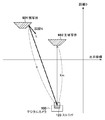
In step S<b>407, the
図5は、撮影された画像上の水平座標と被写体の存在する3次元の座標との関係を示している。本実施形態では、被写体距離情報を用いることにより、画像上の水平方向の差分ΔHに対する、距離(奥行き)Dの差分ΔDが得られる。このため、法線算出部303は、この差分ΔHに対する距離の差分ΔDに基づいて、被写体501の表面形状の勾配を算出することができる。そして、算出した勾配に対する法線を求めることにより、被写体の表面形状における法線ベクトルNを算出することができる。法線算出部303は、同様の処理により撮影画像の各画素に対応する法線を算出し、算出した法線を法線マップとして仮想光源反射成分算出部304に出力する。
FIG. 5 shows the relationship between the horizontal coordinates on the captured image and the three-dimensional coordinates where the subject exists. In the present embodiment, by using the subject distance information, the difference ΔD of the distance (depth) D with respect to the horizontal difference ΔH on the image can be obtained. Therefore, the
S408では、仮想光源反射成分算出部304は、仮想光源を設定して、被写体601における仮想光源による反射成分を算出する。具体的には、本ステップでは、ストロボ発光によって生じた被写体間の陰影状態の差を補うための仮想光源を設定する。換言すれば、設定する仮想光源は、ストロボ発光による主被写体602への影響度(例えば主被写体602の陰影状態の変化)と、ストロボ光による被写体601への影響度(例えば被写体601の陰影状態の変化)の差を低減させるものである。そして、算出される仮想光源の反射成分は、設定された仮想光源によって生じる被写体における陰影状態の変化を表すものであり、ストロボ発光によって生じた被写体間の陰影状態の差を低減する。
In step S<b>408, the virtual light source reflection
仮想光源による反射成分は、各被写体におけるストロボ強度がストロボと被写体との距離Kの二乗に反比例し、且つ、ストロボ光が被写体に照射するストロボ強度とストロボ光が主被写体に照射するストロボ強度との差分と、被写体表面における法線ベクトルNとストロボ光の光源方向ベクトルLの内積とに比例する特性を用いて算出される。 The reflection component of the virtual light source is such that the strobe intensity of each subject is inversely proportional to the square of the distance K between the strobe and the subject, and the strobe intensity with which the strobe light illuminates the subject and the strobe intensity with which the strobe light illuminates the main subject. It is calculated using a characteristic that is proportional to the difference and the inner product of the normal vector N on the subject surface and the light source direction vector L of the strobe light.
この仮想光源による反射成分の具体的な算出方法について、図6を参照して説明する。図6では、撮影時における、主被写体以外の被写体601と、主被写体602と、デジタルカメラ100及びストロボ123との位置の関係を示している。
A specific method of calculating the reflection component by the virtual light source will be described with reference to FIG. FIG. 6 shows the positional relationship between the subject 601, other than the main subject, the main subject 602, the
仮想光源反射成分算出部304は、ストロボ123が被写体601に照射するストロボ強度Skを、ストロボ123と被写体601との距離K、ストロボの光量に基づいた仮想光源の光量αを用いて、式1に従って求めることができる。
The virtual light source reflection
Sk = α / K^2 ・・・ (式1)
なお、光量αは、例えば実際のストロボの光量と同等となるように設定される。
Sk=α/K^2 (Equation 1)
The light amount α is set to be equal to the actual light amount of the strobe, for example.
また、ストロボ123が主被写体602に照射するストロボ強度Smは、ストロボ123と主被写体602との距離Km、ストロボの光量に基づいた仮想光源の光量αを用いて、式2に従って求めることができる。
Further, the strobe intensity Sm that the
Sm = α / Km^2 ・・・ (式2)
なお、光量αは、例えば式1に示すストロボの光量と同一である。
Sm = α / Km^2 (Equation 2)
The light amount α is the same as the light amount of the strobe light shown in Expression 1, for example.
更に、ストロボ123が被写体601に照射するストロボ強度Sk、及び、ストロボ123が主被写体602に照射するストロボ強度Smを用いて、被写体601の表面における仮想光源による反射成分(Ra、Ga、Ba)は、式3に従って求めることができる。
Further, using the strobe intensity Sk that the
Ra = β × (Sm−Sk) × (−L・N) × Rw × Rt
Ga = β × (Sm−Sk) × (−L・N) × Gt
Ba = β × (Sm−Sk) × (−L・N) × Bw × Bt
・・・ (式3)
ここで、Lはストロボ123の3次元ベクトル、法線Nは被写体の3次元法線ベクトル、(Rt、Gt、Bt)はデガンマ処理部302から出力されたRGB信号である。仮想光源反射成分算出部304は、測距センサ124からの被写体距離情報に基づいて距離(K、Km)やLを取得し、法線算出部303からの法線マップに基づいて法線Nを取得する。また、Rw、Bwは光源の色を制御する色パラメータであり、ストロボ123の特性に合わせるための所定の値を設定する。このように色パラメータを用いることにより、仮想光源の反射成分に光源の特性を反映することができる。
Ra=β×(Sm−Sk)×(−L·N)×Rw×Rt
Ga=β×(Sm−Sk)×(−L·N)×Gt
Ba=β×(Sm−Sk)×(−L·N)×Bw×Bt
... (Formula 3)
Here, L is the three-dimensional vector of the
なお、βは仮想光源による反射成分(Ra、Ga、Ba)の調整を行うためのゲインであり、リライティング処理の効果を調整するために設定する。具体的には、ゲインβは、距離K(ストロボ123と被写体601との距離)と距離Ks(ストロボ123と主被写体602との距離)の差分の絶対値に基づいて算出する。
Note that β is a gain for adjusting the reflection component (Ra, Ga, Ba) by the virtual light source, and is set to adjust the effect of the relighting process. Specifically, the gain β is calculated based on the absolute value of the difference between the distance K (distance between the
図7を参照してゲインβの算出例について説明する。図7は、距離Kと距離Ksとの差分の絶対値であるΔK(距離差分の絶対値)からゲインβを算出する変換テーブルの一例を示している。図7に示す横軸は距離差分の絶対値ΔKであり、縦軸はゲインβである。ゲインβは、距離差分の絶対値ΔKが所定の閾値Th0より小さい場合には1.0に設定されて出力される。また、ゲインβは、距離差分の絶対値ΔKが所定の閾値Th1より大きい場合には0.0に設定されて出力される。距離差分の絶対値ΔKが閾値Th0と閾値Th1の間である場合には、ゲインβは1.0〜0.0の間の値に設定されて出力される。 An example of calculating the gain β will be described with reference to FIG. 7. FIG. 7 shows an example of a conversion table for calculating the gain β from ΔK (absolute value of distance difference) which is the absolute value of the difference between the distance K and the distance Ks. The horizontal axis shown in FIG. 7 is the absolute value ΔK of the distance difference, and the vertical axis is the gain β. The gain β is set to 1.0 and output when the absolute value ΔK of the distance difference is smaller than the predetermined threshold Th0. Further, the gain β is set to 0.0 and output when the absolute value ΔK of the distance difference is larger than the predetermined threshold Th1. When the absolute value ΔK of the distance difference is between the threshold Th0 and the threshold Th1, the gain β is set to a value between 1.0 and 0.0 and output.
このように設定されたゲインβを用いることにより、例えば背景の被写体のように、主被写体602と比べてストロボ123からの距離が遠い被写体が、リライティング処理によって主被写体と同程度の明るさとなることを抑圧することができる。すなわち、ストロボを使用する際に自然な明るさに補正することができる。
By using the gain β set in this way, a subject that is farther from the
したがって、式3では、被写体601が主被写体602よりも遠い(被写体601に対する光量が主被写体602に対する光量より不足する)場合、ストロボ強度Smがストロボ強度Skより大きくなり、仮想光源による反射成分は正の値となる。つまり、仮想光源による反射成分によって被写体601の明るさを補うことができる。 Therefore, in Expression 3, when the subject 601 is farther than the main subject 602 (the amount of light for the subject 601 is less than the amount of light for the main subject 602), the strobe intensity Sm becomes larger than the strobe intensity Sk, and the reflection component by the virtual light source is positive. It becomes the value of. That is, the brightness of the subject 601 can be supplemented by the reflection component of the virtual light source.
一方、被写体601が主被写体602よりも近い(被写体601に対する光量が主被写体602に対する光量より過剰となる)場合、ストロボ強度Smがストロボ強度Skより小さくなり、仮想光源による反射成分は負の値となる。つまり、仮想光源による反射成分によって、被写体601の明るさを抑制することができる。 On the other hand, when the subject 601 is closer to the main subject 602 (the amount of light for the subject 601 is more than the amount of light for the main subject 602), the strobe intensity Sm becomes smaller than the strobe intensity Sk, and the reflection component of the virtual light source has a negative value. Become. That is, the brightness of the subject 601 can be suppressed by the reflection component of the virtual light source.
仮想光源反射成分算出部304は、式3に従って算出した仮想光源による反射成分(Ra、Ga、Ba)を仮想光源付加処理部305へ出力する。
The virtual light source reflection
S409では、仮想光源付加処理部305は、上述した仮想光源成分(Ra、Ga、Ba)を撮影画像に付加する。具体的に、仮想光源付加処理部305は、以下の式に従って、仮想光源成分(Ra、Ga、Ba)を、デガンマ処理部302から出力されたリニア変換後のRGB信号(Rt、Gt、Bt)に付加する。
Rout = Rt + Ra
Gout = Gt + Ga
Bout = Bt + Ra
In S409, the virtual light source
Rout = Rt + Ra
Gout = Gt + Ga
Bout = Bt + Ra
このように、ストロボの特性を反映した仮想光源による反射成分を撮影画像の信号に付加することにより、発光させる光源の特性を反映した陰影の調整を行うことができる。そして、仮想光源付加処理部305から出力されたRGB信号(Rout、Gout、Bout)はガンマ処理部306に入力される。
In this way, by adding the reflection component of the virtual light source that reflects the characteristics of the strobe to the signal of the captured image, it is possible to adjust the shadow that reflects the characteristics of the light source that emits light. Then, the RGB signals (Rout, Gout, Bout) output from the virtual light source
S410では、ガンマ処理部306は、仮想光源付加処理部305から出力されたRGB信号(Rout、Gout、Bout)にガンマ補正を行う。ガンマ補正後のRGB信号(R´out、G´out、B´out)は、輝度色差信号変換部307へ出力される。
In S410, the
S411では、輝度色差信号変換部307は、ガンマ補正後のRGB信号(R´out、G´out、B´out)から輝度Y、色差信号R−Y、B−Y信号を生成し、画像メモリ106に出力し、本処理に係る一連の動作を終了する。
In step S411, the luminance/color difference
なお、本実施形態では、ストロボ123とデジタルカメラ100とが一体である場合を例に説明した。しかし、ストロボ123がデジタルカメラ100から離れた場所に設置され、通信(有線又は無線)によりデジタルカメラ100と接続されてもよい。この場合、仮想光源反射成分算出部304は、ストロボ123の位置情報を予め取得することにより、本実施形態と同様に仮想光源による反射成分を算出することができる。
In the present embodiment, the case where the
また、仮想光源反射成分算出部304は、絞りを備えるシャッター102から絞り値の情報を更に取得し、取得した絞り値の情報を用いて仮想光源の光量αを調整してもよい。絞り値の情報を更に参照することにより、ストロボ123から照射される光に対する絞りの影響を考量して、リライティング処理の精度を向上させることができる。仮想光源反射成分算出部304は、また、ストロボ123の照射角に基づき、ストロボ123の光軸からの角度によって仮想光源の光量αを調整してもよい。
Further, the virtual light source reflection
また、被写体601が主被写体602よりもストロボ123に近い位置に存在する場合、ストロボ強度Smがストロボ強度Skより小さい値となり、仮想光源による反射成分(Ra、Ga、Ba)は、式3において負の値となる。また、主被写体602を基準に露出を調整するため、被写体601の一部が飽和する場合がある。このため、被写体601に飽和している領域がある場合には、被写体601の陰影状態が仮想光源による反射成分によって適切に補正できなくなる。そこで、被写体601が主被写体602よりもストロボ123に近い位置に存在する場合には、周辺の非飽和領域のRGB信号(Rout、Gout、Bout)を用いて飽和領域を補間してもよい。
Further, when the subject 601 is closer to the
以上説明したように本実施形態では、複数の被写体がストロボ123から異なる距離に存在する場合、ストロボ123による被写体601における陰影状態の変化とストロボ123による主被写体における陰影状態の変化との差を低減する仮想光源を設定した。またこの仮想光源の特性は、ストロボ123の特性に基づいて決定した。これにより、ストロボ等の照明装置を使用した場合でも、照明装置の特性を反映した被写体領域の明るさの調整(すなわちリライティング)を行うことができる。換言すれば、発光させる光源からの距離が異なる複数の被写体を撮影した画像に、光源の特性を反映した陰影の調整を行うことが可能になる。
As described above, in the present embodiment, when a plurality of subjects are present at different distances from the
(その他の実施形態)
本発明は、上述の実施形態の1以上の機能を実現するプログラムを、ネットワーク又は記憶媒体を介してシステム又は装置に供給し、そのシステム又は装置のコンピュータにおける1つ以上のプロセッサがプログラムを読出し実行する処理でも実現可能である。また、1以上の機能を実現する回路(例えば、ASIC)によっても実現可能である。
(Other embodiments)
The present invention supplies a program that implements one or more functions of the above-described embodiments to a system or apparatus via a network or a storage medium, and one or more processors in a computer of the system or apparatus read and execute the program. It can also be realized by the processing. It can also be realized by a circuit (for example, ASIC) that realizes one or more functions.
50…システム制御部、103…撮像部、114…リライティング処理部、304…仮想光源反射成分算出部、305…仮想光源付加処理部 50... System control unit, 103... Imaging unit, 114... Relighting processing unit, 304... Virtual light source reflection component calculation unit, 305... Virtual light source addition processing unit
Claims (13)
前記所定の光源の特性に基づいて、前記画像に適用する仮想光源を設定する設定手段と、
前記仮想光源によって前記画像に含まれる複数の被写体の少なくともいずれかの陰影状態を変更した画像を生成する生成手段と、を備え、
前記設定手段は、前記画像に含まれる、第1の被写体と第2の被写体とが前記所定の光源から異なる距離に存在する場合に、前記所定の光源による前記第1の被写体における陰影状態の変化と前記所定の光源による前記第2の被写体における陰影状態の変化との差を低減するように、前記仮想光源を設定し、更に、前記設定手段は、前記第1の被写体における前記仮想光源による陰影状態の変化が前記差を低減するように、前記仮想光源を設定し、
前記第1の被写体における前記仮想光源による陰影状態の変化は、前記第1の被写体における前記仮想光源の反射成分であり、
前記生成手段は、前記第1の被写体の陰影状態を変更した画像を生成する、
ことを特徴とする画像処理装置。 An acquisition unit that acquires an image captured with the emission of light from a predetermined light source,
Based on the characteristics of the predetermined light source, setting means for setting a virtual light source to be applied to the image,
Generating means for generating an image in which the shadow state of at least one of the plurality of subjects included in the image is changed by the virtual light source,
When the first subject and the second subject included in the image are present at different distances from the predetermined light source, the setting unit changes the shadow state of the first subject by the predetermined light source. so as to reduce the difference between the change in the shading state in the second object by the predetermined light source and to set the virtual light source, further, the setting means, shading by the virtual light source in the first object Setting the virtual light source such that a change in state reduces the difference,
The change in the shaded state of the first subject due to the virtual light source is a reflection component of the virtual light source at the first subject,
The generating unit generates an image in which a shaded state of the first subject is changed,
An image processing device characterized by the above.
ことを特徴とする請求項1に記載の画像処理装置。 The setting means determines that a change in a shadow state of the first subject due to the virtual light source is a distance from the predetermined light source to the first subject and a distance from the predetermined light source to the second subject. The virtual light source is set so as to change according to the difference,
The image processing apparatus according to claim 1 , wherein:
ことを特徴とする請求項1又は2に記載の画像処理装置。 In the setting means, a change in a shadow state of the first subject caused by the virtual light source is determined by a light intensity of the predetermined light source of the first subject and a light intensity of the predetermined light source of the second subject. The virtual light source is set so as to change according to the difference between
The image processing apparatus according to claim 1 or 2, characterized in that.
ことを特徴とする請求項1から3のいずれか1項に記載の画像処理装置。 The setting unit sets the virtual light source such that a change in a shadow state of the first subject due to the virtual light source changes according to a state of an aperture when the image is captured,
The image processing apparatus according to any one of claims 1 to 3 , characterized in that.
前記生成手段は、前記所定の光源から前記第1の被写体までの距離が前記所定の光源から前記第2の被写体までの距離より近い場合、前記第1の被写体の飽和していない信号に基づいて、陰影状態を変更した画像を生成する、
ことを特徴とする請求項1から4のいずれか1項に記載の画像処理装置。 The image is an image taken by adjusting the brightness with the second subject as a reference,
When the distance from the predetermined light source to the first subject is shorter than the distance from the predetermined light source to the second subject, the generating means is based on the unsaturated signal of the first subject. , Generate an image with changed shaded state,
The image processing apparatus according to any one of claims 1 to 4 , characterized in that:
ことを特徴とする請求項1から5のいずれか1項に記載の画像処理装置。 The second subject is a main subject, and the first subject is a subject different from the main subject,
The image processing apparatus according to any one of claims 1 to 5 , characterized in that.
ことを特徴とする請求項1から6のいずれか1項に記載の画像処理装置。 The predetermined light source is a strobe, and the characteristic of the predetermined light source includes a characteristic regarding a color of the light source,
The image processing apparatus according to any one of claims 1 to 6 , characterized in that.
請求項1から7のいずれか1項に記載の画像処理装置と、を備える、
ことを特徴とする撮像装置。 An image sensor for outputting a captured image,
An image processing apparatus according to any one of claims 1 to 7 , comprising:
An imaging device characterized by the above.
ことを特徴とする請求項8に記載の撮像装置。 Further comprising a light emitting device which is the predetermined light source, which emits light when taking a picture,
The imaging device according to claim 8 , wherein
設定手段が、前記所定の光源の特性に基づいて、前記画像に適用する仮想光源を設定する設定工程と、
生成手段が、前記仮想光源によって前記画像に含まれる複数の被写体の少なくともいずれかの陰影状態を変更した画像を生成する生成工程と、を備え、
前記設定工程では、前記画像に含まれる、第1の被写体と第2の被写体とが前記所定の光源から異なる距離に存在する場合に、前記所定の光源による前記第1の被写体における陰影状態の変化と前記所定の光源による前記第2の被写体における陰影状態の変化との差を低減するように、前記仮想光源を設定し、
更に、前記設定工程では、前記第1の被写体における前記仮想光源による陰影状態の変化が前記差を低減するように、前記仮想光源を設定し、
前記第1の被写体における前記仮想光源による陰影状態の変化は、前記第1の被写体における前記仮想光源の反射成分であり、
前記生成工程では、前記第1の被写体の陰影状態を変更した画像を生成する、
ことを特徴とする画像処理装置の制御方法。 An acquisition step in which the acquisition means acquires an image captured with the emission of a predetermined light source;
A setting step, based on the characteristics of the predetermined light source, a setting step of setting a virtual light source to be applied to the image;
And a generating step of generating an image in which at least one of a plurality of subjects included in the image is changed in a shaded state by the virtual light source,
In the setting step, when the first subject and the second subject included in the image are present at different distances from the predetermined light source, the change of the shadow state of the first subject by the predetermined light source. so as to reduce the difference between the change in the shading state in the second object by the predetermined light source and to set the virtual light source,
Furthermore, in the setting step, the virtual light source is set such that a change in a shadow state of the first subject caused by the virtual light source reduces the difference.
The change in the shaded state of the first subject due to the virtual light source is a reflection component of the virtual light source at the first subject,
In the generating step, an image in which the shaded state of the first subject is changed is generated,
A method for controlling an image processing apparatus, comprising:
撮像素子が、前記発光装置の発光を伴って画像を撮影する撮影工程と、
設定手段が、前記発光装置の特性に基づいて、前記画像に適用する仮想光源を設定する設定工程と、
生成手段が、前記仮想光源によって前記画像に含まれる複数の被写体の少なくともいずれかの陰影状態を変更した画像を生成する生成工程と、を備え、
前記設定工程では、前記画像に含まれる、第1の被写体と第2の被写体とが前記発光装置から異なる距離に存在する場合に、前記発光装置による前記第1の被写体における陰影状態の変化と前記発光装置による前記第2の被写体における陰影状態の変化との差を低減するように、前記仮想光源を設定し、
更に、前記設定工程では、前記第1の被写体における前記仮想光源による陰影状態の変化が前記差を低減するように、前記仮想光源を設定し、
前記第1の被写体における前記仮想光源による陰影状態の変化は、前記第1の被写体における前記仮想光源の反射成分であり、
前記生成工程では、前記第1の被写体の陰影状態を変更した画像を生成する、
ことを特徴とする撮像装置の制御方法。 A method for controlling an image pickup device including an image pickup element and a light emitting device, comprising:
A photographing step in which the image pickup element photographs an image with the light emission of the light emitting device;
A setting step in which the setting means sets a virtual light source to be applied to the image based on the characteristics of the light emitting device;
And a generating step of generating an image in which at least one of a plurality of subjects included in the image is changed in a shaded state by the virtual light source,
In the setting step, when the first subject and the second subject included in the image exist at different distances from the light emitting device, the change in the shadow state of the first subject by the light emitting device and the change in the shadow state of the first subject. so as to reduce the difference between the change in the shading state in the second object by the light-emitting device, and set the virtual light source,
Furthermore, in the setting step, the virtual light source is set such that a change in a shadow state of the first subject caused by the virtual light source reduces the difference.
The change in the shaded state of the first subject due to the virtual light source is a reflection component of the virtual light source at the first subject,
In the generating step, an image in which the shaded state of the first subject is changed is generated,
A method of controlling an imaging device, comprising:
Priority Applications (2)
| Application Number | Priority Date | Filing Date | Title |
|---|---|---|---|
| JP2016036313A JP6718256B2 (en) | 2016-02-26 | 2016-02-26 | Image processing device, imaging device, control method thereof, and program |
| US15/435,504 US10021314B2 (en) | 2016-02-26 | 2017-02-17 | Image processing apparatus, image capturing apparatus, method of controlling the same, and storage medium for changing shading using a virtual light source |
Applications Claiming Priority (1)
| Application Number | Priority Date | Filing Date | Title |
|---|---|---|---|
| JP2016036313A JP6718256B2 (en) | 2016-02-26 | 2016-02-26 | Image processing device, imaging device, control method thereof, and program |
Publications (3)
| Publication Number | Publication Date |
|---|---|
| JP2017153045A JP2017153045A (en) | 2017-08-31 |
| JP2017153045A5 JP2017153045A5 (en) | 2019-04-04 |
| JP6718256B2 true JP6718256B2 (en) | 2020-07-08 |
Family
ID=59679973
Family Applications (1)
| Application Number | Title | Priority Date | Filing Date |
|---|---|---|---|
| JP2016036313A Active JP6718256B2 (en) | 2016-02-26 | 2016-02-26 | Image processing device, imaging device, control method thereof, and program |
Country Status (2)
| Country | Link |
|---|---|
| US (1) | US10021314B2 (en) |
| JP (1) | JP6718256B2 (en) |
Families Citing this family (2)
| Publication number | Priority date | Publication date | Assignee | Title |
|---|---|---|---|---|
| JP6995554B2 (en) * | 2017-10-02 | 2022-01-14 | キヤノン株式会社 | Imaging device and imaging method |
| JP7292905B2 (en) * | 2019-03-06 | 2023-06-19 | キヤノン株式会社 | Image processing device, image processing method, and imaging device |
Family Cites Families (4)
| Publication number | Priority date | Publication date | Assignee | Title |
|---|---|---|---|---|
| JP5237066B2 (en) * | 2008-11-28 | 2013-07-17 | キヤノン株式会社 | Mixed reality presentation system, mixed reality presentation method, and program |
| US20120120071A1 (en) * | 2010-07-16 | 2012-05-17 | Sony Ericsson Mobile Communications Ab | Shading graphical objects based on face images |
| JP5699652B2 (en) | 2011-02-07 | 2015-04-15 | 株式会社ニコン | Camera and camera system |
| JP6442209B2 (en) * | 2014-09-26 | 2018-12-19 | キヤノン株式会社 | Image processing apparatus and control method thereof |
-
2016
- 2016-02-26 JP JP2016036313A patent/JP6718256B2/en active Active
-
2017
- 2017-02-17 US US15/435,504 patent/US10021314B2/en active Active
Also Published As
| Publication number | Publication date |
|---|---|
| US20170251136A1 (en) | 2017-08-31 |
| JP2017153045A (en) | 2017-08-31 |
| US10021314B2 (en) | 2018-07-10 |
Similar Documents
| Publication | Publication Date | Title |
|---|---|---|
| JP6445844B2 (en) | Imaging device and method performed in imaging device | |
| JP5108093B2 (en) | Imaging apparatus and imaging method | |
| JP5743696B2 (en) | Image processing apparatus, image processing method, and program | |
| JP6049343B2 (en) | Image processing apparatus, image processing method, and program | |
| JP2009212853A (en) | White balance controller, its control method, and imaging apparatus | |
| JP6381404B2 (en) | Image processing apparatus and method, and imaging apparatus | |
| JP6463177B2 (en) | Image processing apparatus and control method thereof | |
| JP2013058858A (en) | Image processor, image processing method, and program | |
| JP7059076B2 (en) | Image processing device, its control method, program, recording medium | |
| JP6718256B2 (en) | Image processing device, imaging device, control method thereof, and program | |
| JP2018182699A (en) | Image processing apparatus, control method of the same, program, and storage medium | |
| JP2010183460A (en) | Image capturing apparatus and method of controlling the same | |
| JP2018092350A (en) | Image processing apparatus, image processing method, and program | |
| JP6570311B2 (en) | Image processing apparatus and image processing method | |
| CN112911161B (en) | Image processing apparatus, image processing method, image capturing apparatus, and storage medium | |
| JP6541416B2 (en) | IMAGE PROCESSING APPARATUS, IMAGE PROCESSING METHOD, PROGRAM, AND STORAGE MEDIUM | |
| JP2018107741A (en) | Image processing system, image processing method, and program | |
| JP2018182700A (en) | Image processing apparatus, control method of the same, program, and storage medium | |
| JP2017138927A (en) | Image processing device, imaging apparatus, control method and program thereof | |
| KR20110074417A (en) | Image taking device and method and program for taking image therewith | |
| JP2015119436A (en) | Imaging apparatus | |
| JP7011694B2 (en) | Image processing equipment and its control method, program | |
| JP6601062B2 (en) | Imaging control apparatus, imaging control method, and program | |
| US9936158B2 (en) | Image processing apparatus, method and program | |
| JP2021087125A (en) | Image processing device, control method thereof, and program |
Legal Events
| Date | Code | Title | Description |
|---|---|---|---|
| A521 | Request for written amendment filed |
Free format text: JAPANESE INTERMEDIATE CODE: A523 Effective date: 20190221 |
|
| A621 | Written request for application examination |
Free format text: JAPANESE INTERMEDIATE CODE: A621 Effective date: 20190221 |
|
| A977 | Report on retrieval |
Free format text: JAPANESE INTERMEDIATE CODE: A971007 Effective date: 20191106 |
|
| A131 | Notification of reasons for refusal |
Free format text: JAPANESE INTERMEDIATE CODE: A131 Effective date: 20191111 |
|
| A521 | Request for written amendment filed |
Free format text: JAPANESE INTERMEDIATE CODE: A523 Effective date: 20191227 |
|
| TRDD | Decision of grant or rejection written | ||
| A01 | Written decision to grant a patent or to grant a registration (utility model) |
Free format text: JAPANESE INTERMEDIATE CODE: A01 Effective date: 20200515 |
|
| A61 | First payment of annual fees (during grant procedure) |
Free format text: JAPANESE INTERMEDIATE CODE: A61 Effective date: 20200612 |
|
| R151 | Written notification of patent or utility model registration |
Ref document number: 6718256 Country of ref document: JP Free format text: JAPANESE INTERMEDIATE CODE: R151 |