JP7059076B2 - Image processing device, its control method, program, recording medium - Google Patents
Image processing device, its control method, program, recording medium Download PDFInfo
- Publication number
- JP7059076B2 JP7059076B2 JP2018069289A JP2018069289A JP7059076B2 JP 7059076 B2 JP7059076 B2 JP 7059076B2 JP 2018069289 A JP2018069289 A JP 2018069289A JP 2018069289 A JP2018069289 A JP 2018069289A JP 7059076 B2 JP7059076 B2 JP 7059076B2
- Authority
- JP
- Japan
- Prior art keywords
- image
- mode
- distribution information
- distance distribution
- acquisition means
- Prior art date
- Legal status (The legal status is an assumption and is not a legal conclusion. Google has not performed a legal analysis and makes no representation as to the accuracy of the status listed.)
- Active
Links
- 238000012545 processing Methods 0.000 title claims description 113
- 238000000034 method Methods 0.000 title claims description 71
- 230000000694 effects Effects 0.000 claims description 17
- 238000006243 chemical reaction Methods 0.000 description 10
- 208000029152 Small face Diseases 0.000 description 8
- 238000010586 diagram Methods 0.000 description 8
- 238000012937 correction Methods 0.000 description 7
- 230000006870 function Effects 0.000 description 7
- 230000007274 generation of a signal involved in cell-cell signaling Effects 0.000 description 6
- 230000001678 irradiating effect Effects 0.000 description 6
- 238000001514 detection method Methods 0.000 description 5
- 238000005259 measurement Methods 0.000 description 4
- 230000003321 amplification Effects 0.000 description 3
- 238000003199 nucleic acid amplification method Methods 0.000 description 3
- 238000011156 evaluation Methods 0.000 description 2
- 201000005569 Gout Diseases 0.000 description 1
- 238000005282 brightening Methods 0.000 description 1
- 230000006835 compression Effects 0.000 description 1
- 238000007906 compression Methods 0.000 description 1
- 238000003384 imaging method Methods 0.000 description 1
- 239000011159 matrix material Substances 0.000 description 1
- 230000003287 optical effect Effects 0.000 description 1
- 238000001454 recorded image Methods 0.000 description 1
- 239000002689 soil Substances 0.000 description 1
- 230000002194 synthesizing effect Effects 0.000 description 1
- 230000003313 weakening effect Effects 0.000 description 1
Images


Classifications
-
- G06T5/94—
-
- H—ELECTRICITY
- H04—ELECTRIC COMMUNICATION TECHNIQUE
- H04N—PICTORIAL COMMUNICATION, e.g. TELEVISION
- H04N5/00—Details of television systems
- H04N5/222—Studio circuitry; Studio devices; Studio equipment
- H04N5/262—Studio circuits, e.g. for mixing, switching-over, change of character of image, other special effects ; Cameras specially adapted for the electronic generation of special effects
- H04N5/2621—Cameras specially adapted for the electronic generation of special effects during image pickup, e.g. digital cameras, camcorders, video cameras having integrated special effects capability
-
- G—PHYSICS
- G06—COMPUTING; CALCULATING OR COUNTING
- G06T—IMAGE DATA PROCESSING OR GENERATION, IN GENERAL
- G06T5/00—Image enhancement or restoration
- G06T5/50—Image enhancement or restoration by the use of more than one image, e.g. averaging, subtraction
-
- G—PHYSICS
- G06—COMPUTING; CALCULATING OR COUNTING
- G06T—IMAGE DATA PROCESSING OR GENERATION, IN GENERAL
- G06T7/00—Image analysis
- G06T7/50—Depth or shape recovery
- G06T7/55—Depth or shape recovery from multiple images
- G06T7/593—Depth or shape recovery from multiple images from stereo images
-
- H—ELECTRICITY
- H04—ELECTRIC COMMUNICATION TECHNIQUE
- H04N—PICTORIAL COMMUNICATION, e.g. TELEVISION
- H04N13/00—Stereoscopic video systems; Multi-view video systems; Details thereof
- H04N13/20—Image signal generators
- H04N13/271—Image signal generators wherein the generated image signals comprise depth maps or disparity maps
-
- H—ELECTRICITY
- H04—ELECTRIC COMMUNICATION TECHNIQUE
- H04N—PICTORIAL COMMUNICATION, e.g. TELEVISION
- H04N23/00—Cameras or camera modules comprising electronic image sensors; Control thereof
- H04N23/10—Cameras or camera modules comprising electronic image sensors; Control thereof for generating image signals from different wavelengths
-
- H—ELECTRICITY
- H04—ELECTRIC COMMUNICATION TECHNIQUE
- H04N—PICTORIAL COMMUNICATION, e.g. TELEVISION
- H04N23/00—Cameras or camera modules comprising electronic image sensors; Control thereof
- H04N23/60—Control of cameras or camera modules
- H04N23/667—Camera operation mode switching, e.g. between still and video, sport and normal or high- and low-resolution modes
-
- H—ELECTRICITY
- H04—ELECTRIC COMMUNICATION TECHNIQUE
- H04N—PICTORIAL COMMUNICATION, e.g. TELEVISION
- H04N23/00—Cameras or camera modules comprising electronic image sensors; Control thereof
- H04N23/80—Camera processing pipelines; Components thereof
-
- G—PHYSICS
- G06—COMPUTING; CALCULATING OR COUNTING
- G06T—IMAGE DATA PROCESSING OR GENERATION, IN GENERAL
- G06T2207/00—Indexing scheme for image analysis or image enhancement
- G06T2207/10—Image acquisition modality
- G06T2207/10004—Still image; Photographic image
- G06T2207/10012—Stereo images
-
- G—PHYSICS
- G06—COMPUTING; CALCULATING OR COUNTING
- G06T—IMAGE DATA PROCESSING OR GENERATION, IN GENERAL
- G06T2207/00—Indexing scheme for image analysis or image enhancement
- G06T2207/30—Subject of image; Context of image processing
- G06T2207/30196—Human being; Person
- G06T2207/30201—Face
-
- H—ELECTRICITY
- H04—ELECTRIC COMMUNICATION TECHNIQUE
- H04N—PICTORIAL COMMUNICATION, e.g. TELEVISION
- H04N13/00—Stereoscopic video systems; Multi-view video systems; Details thereof
- H04N2013/0074—Stereoscopic image analysis
- H04N2013/0081—Depth or disparity estimation from stereoscopic image signals
Description
本発明は、画像処理装置に関し、特に入力された画像の明るさを補正する画像処理装置に関するものである。 The present invention relates to an image processing device, and more particularly to an image processing device that corrects the brightness of an input image.
従来から写真撮影においては、補助照明やレフ板による光の調整によって、被写体に生じる光と影の領域の調整が行われている。これにより、被写体の印象をさまざまに変化させた写真撮影が可能となる。また、これらの光の調整を撮影後に行う技術として、被写体の形状情報を利用して仮想的な光源による光と影を被写体像に加える方法がある。 Conventionally, in photography, the area of light and shadow generated in a subject has been adjusted by adjusting the light by an auxiliary lighting or a reflector. This makes it possible to take photographs with various impressions of the subject. Further, as a technique for adjusting these lights after shooting, there is a method of adding light and shadow by a virtual light source to a subject image by using the shape information of the subject.
これにより、絵画的な印象深い画像にすることや、ハイライトと陰影を付けることで立体感を強調した画像にすることが可能となる。被写体の形状情報を取得する方法としては、測距センサを用いる方法や、複数枚の画像の視差情報から距離マップデータを生成する方法がある。この距離マップは種々の要因によりエラーを含んでいる場合があり、そのため距離マップの各画素の距離情報を補正する技術が提案されている。 This makes it possible to create an impressive pictorial image, or to create an image that emphasizes the three-dimensional effect by adding highlights and shadows. As a method of acquiring the shape information of the subject, there are a method of using a distance measuring sensor and a method of generating distance map data from the parallax information of a plurality of images. This distance map may contain an error due to various factors, and therefore a technique for correcting the distance information of each pixel of the distance map has been proposed.
例えば、特許文献1では、補正対象画素の演算範囲内の複数の画素の画素値及び距離値を用いて、クラスタリングを行い、そのクラスタリング結果に基づいて、補正対象画素の距離値を算出することで、各画素の距離情報を補正している。 For example, in Patent Document 1, clustering is performed using the pixel values and distance values of a plurality of pixels within the calculation range of the correction target pixel, and the distance value of the correction target pixel is calculated based on the clustering result. , The distance information of each pixel is corrected.
しかしながら、どのような距離マップなどの被写体情報を用いるのが最適であるかは、どのような画像処理を行うか、例えばどのような仮想的な光源を用いて被写体に効果を付加するかによって異なる。 However, what kind of distance map or other subject information is optimal to use depends on what kind of image processing is performed, for example, what kind of virtual light source is used to add the effect to the subject. ..
本発明に係る画像処理装置は、画像に対して仮想光の効果を付与するリライティング処理を行う画像処理装置であって、前記画像に含まれる被写体の距離分布情報を取得する複数の取得手段を有し、ここで前記複数の取得手段は、前記画像の視差情報に基づく、前記画像に含まれる被写体の距離分布情報を取得する第1の取得手段と、前記視差情報とは異なる特徴量に基づく、前記画像に含まれる被写体の距離分布情報を取得する第2の取得手段と、を含み、前記設定手段により設定されたモードに基づき、前記複数の取得手段のうち、どの取得手段により取得された距離分布情報を用いて前記リライティング処理を行うかを決定する決定手段をさらに有することを特徴とする。 The image processing device according to the present invention is an image processing device that performs rewriting processing for imparting an effect of virtual light to an image, and has a plurality of acquisition means for acquiring distance distribution information of a subject included in the image. However , here, the plurality of acquisition means are based on the first acquisition means for acquiring the distance distribution information of the subject included in the image based on the disparity information of the image and the feature amount different from the disparity information. A second acquisition means for acquiring the distance distribution information of the subject included in the image, and a distance acquired by any of the plurality of acquisition means based on the mode set by the setting means . It is characterized by further having a determination means for determining whether to perform the rewriting process using the distribution information.
本発明によれば、状況に適した被写体情報の取得を行うことが可能である。 According to the present invention, it is possible to acquire subject information suitable for the situation.
以下に、本発明の好ましい実施の形態を、添付の図面に基づいて詳細に説明する。本実施例では、画像処理装置としてデジタルカメラに適用した例について説明する。 Hereinafter, preferred embodiments of the present invention will be described in detail with reference to the accompanying drawings. In this embodiment, an example applied to a digital camera as an image processing device will be described.
<実施例1>
以下、図面を参照して、本発明の第1の実施例における、デジタルカメラについて説明する。
<Example 1>
Hereinafter, the digital camera according to the first embodiment of the present invention will be described with reference to the drawings.
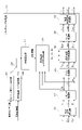
図1は、本発明の実施形態によるデジタルカメラの構成例を示すブロック図である。 FIG. 1 is a block diagram showing a configuration example of a digital camera according to an embodiment of the present invention.
図1において、100はデジタルカメラ全体、101はズームレンズ、フォーカスレンズを含むレンズ群、102は絞り機能を備えるシャッター、103は光学像を電気信号に変換するCCDやCMOS素子等で構成される撮像部である。104は、アナログ信号をデジタル信号に変換するA/D変換器、105はA/D変換器104から出力される画像データに対し、ホワイトバランス処理や、γ処理、輪郭強調、色補正処理などの各種画像処理を行う画像処理部である。106は画像メモリ、107は画像メモリ106を制御するメモリ制御部、108は入力デジタル信号をアナログ信号に変換するD/A変換器、109はLCD等の表示器、110は画像データを圧縮符号化・復号化するコーデック部である。111は記録媒体200とのインタフェースI/F、112はメモリカードやハードディスク等の記録媒体、113は、撮影画像中から顔が映っている領域を検出する顔検出処理部である。114は、撮影画像にリライティング処理を行うリライティング処理部、50はデジタルカメラ100のシステム全体を制御するシステム制御部である。また、121は、プログラムやパラメータなどを格納するEEPROMなどの不揮発性メモリであり、122はシステム制御部50の動作用の定数、変数、不揮発性メモリ124から読みだしたプログラム等を展開するシステムメモリである。123はストロボなどの物理的な光源装置、124は被写体とデジタルカメラ100との距離を測定し、撮影画素の距離情報を2次元の距離マップ画像として出力する測距センサである。本実施例の測距センサ124はいわゆる視差画像を用いた測距を行う。測距センサ124は独立したセンサであってもよいし、撮像部103(例えばCMOSセンサの撮像面)が測距センサ124を兼ねてもよい。例えば撮像部103の画素単位で視差画像を取得する構成を採用すれば、画素ごとに被写体距離が取得できるため、画素単位の距離マップ画像を生成することができる。
In FIG. 1, 100 is an entire digital camera, 101 is a lens group including a zoom lens and a focus lens, 102 is a shutter having an aperture function, and 103 is an image pickup composed of a CCD or a CMOS element that converts an optical image into an electric signal. It is a department.
なお、デジタルカメラの構成は図1に示した構成には限定されない。例えば1つのハードウェアが、実行するプログラムに応じて複数の処理部や制御部などとして機能してもよい。逆に、複数のハードウェアが協働して1つの処理部や制御部などとして機能してもよい。また、各種の処理はプログラムに従い実行されてもよいし、各種処理を行うための回路を設けてもよい。 The configuration of the digital camera is not limited to the configuration shown in FIG. For example, one piece of hardware may function as a plurality of processing units, control units, or the like depending on the program to be executed. On the contrary, a plurality of hardware may cooperate to function as one processing unit, control unit, or the like. Further, various processes may be executed according to a program, or a circuit for performing various processes may be provided.
以上が、デジタルカメラ100の構成である。次に、上記のように構成されたデジタルカメラ100における被写体撮影時の基本動作について説明する。撮像部103は、レンズ101及びシャッター102を介して入射した光を光電変換し、入力画像信号としてA/D変換器104へ出力する。A/D変換器104は撮像部103から出力されるアナログ画像信号をデジタル画像信号に変換し画像処理部105に出力する。
The above is the configuration of the
画像処理部105は、A/D変換器104からの画像データ、又は、メモリ制御部107からの画像データに対し、ホワイトバランスなどの色変換処理、γ処理、輪郭強調処理などを行う。また、画像処理部105では、顔検出部113の顔検出結果や、撮像した画像データを用いて所定の評価値算出処理を行い、得られた評価値結果に基づいてシステム制御部50が露光制御、測距制御を行う。これにより、TTL(スルー・ザ・レンズ)方式のAF(オートフォーカス)処理、AE(自動露出)処理、AWB(オートホワイトバランス)処理などを行う。
The
画像処理部105から出力された画像データは、メモリ制御部107を介して画像メモリ106に書き込まれる。画像メモリ106は、撮像部103から出力された画像データや、表示部109に表示するための画像データを格納する。
The image data output from the
また、D/A変換器108は、画像メモリ106に格納されている画像表示用のデータをアナログ信号に変換して表示部109に供給する。表示部109は、LCD等の表示器上に、D/A変換器108からのアナログ信号に応じた表示を行う。
Further, the D /
コーデック部110は、画像メモリ106に記録された画像データをJPEG,MPEGなどの規格に基づきそれぞれ圧縮符号化する。システム制御部50は符号化した画像データを関連付けて、記録インタフェース111を介して記録媒体に格納する。
The
以上、被写体撮影時の基本動作について説明した。 The basic operation when shooting a subject has been described above.
上記の基本動作以外に、システム制御部50は、前述した不揮発性メモリ124に記録されたプログラムを実行することで、後述する本実施形態の各処理を実現する。ここでいうプログラムとは、本実施形態にて後述する各種フローチャートを実行するためのプログラムのことである。この際、システム制御部50の動作用の定数、変数、不揮発性メモリ121から読み出したプログラム等をシステムメモリ122に展開する。
In addition to the above basic operations, the
次に、画像処理部105の詳細について図2を用いて説明する。図2は画像処理部105の構成を示すブロック図である。なお、図2、図3に示す構成を実現するための具体的な構成は種々の形態が考えられる。例えば図2、図3に示す1つの部分ごとに1つのハードウェアを用意してもよいし、1つのハードウェアが複数の部分として機能してもよい。また、画像処理部105以外のハードウェアを含む複数のハードウェアが共同して図2、図3に示すいずれかの部分として機能してもよい。
Next, the details of the
図2において、200は同時化処理部、201はWB増幅部、202は輝度・色信号生成部、203は輪郭強調処理部、204は輝度ガンマ処理部、205は色変換処理部、206は色γ処理部、207は色差信号生成部、である。 In FIG. 2, 200 is a simultaneous processing unit, 201 is a WB amplification unit, 202 is a luminance / color signal generation unit, 203 is a contour enhancement processing unit, 204 is a luminance gamma processing unit, 205 is a color conversion processing unit, and 206 is a color. The γ processing unit and 207 are color difference signal generation units.
次に、画像処理部105における処理について説明する。図1のA/D変換部104から入力された画像信号が画像処理部105に入力される。
Next, the processing in the
画像処理部105に入力された画像信号は同時化処理部200に入力される。同時化処理部200は入力されたベイヤーRGBの画像データに対して、同時化処理を行い、色信号R,G,Bを生成する。WB増幅部201は、システム制御部50が算出するホワイトバランスゲイン値に基づき、RGBの色信号にゲインをかけ、ホワイトバランスを調整する。WB増幅部201が出力したRGB信号は輝度・色信号生成部202に入力される。輝度・色信号生成部202RGB信号から輝度信号Yを生成し、生成した輝度信号Yを輪郭強調処理部203、色信号RGBを色変換処理部205へ出力する。
The image signal input to the
輪郭強調処理部203では、輝度信号に対して輪郭強調処理を行い、輝度ガンマ処理部204へ出力する。輝度ガンマ処理部204では輝度信号Yに対してガンマ補正を行い、輝度信号Yを画像メモリ106に出力する。
The contour
色変換処理部205は、RGB信号に対するマトリクス演算などにより、所望のカラーバランスへ変換する。色ガンマ処理部206では、RGBの色信号にガンマ補正を行う。色差信号生成部207では、RGB信号から色差信号R-Y、B-Y信号を生成する。
The color
画像メモリ106に出力された画像信号Y,R-Y,B-Y信号は、コーデック部110によって圧縮符号化し、記録媒体200に記録する。
The image signals Y, RY, and BY signals output to the
また、色変換処理部205の出力RGB信号は陰影情報取得部208へも入力する。
Further, the output RGB signal of the color
次にリライティング処理部114の構成および動作について図3を用いて説明する。本実施例でいうリライティング処理とは、仮想的な光源を想定し、撮影により得られた画像に仮想光源により照らされた効果を付与する処理である。本実施例におけるリライティング処理は、例えば撮影前にリライティング処理を行うかをユーザ操作などに基づき設定しておくことで、撮影時に実行される。もちろん、撮影のたびにリライティング処理を行うかをユーザに確認する構成にしてもよいし、撮影・記録済みの画像に対してユーザが任意のタイミングでリライティング処理を行うよう指示してもよい。
Next, the configuration and operation of the
ユーザ操作によりリライティング処理を行うよう選択された場合は、画像処理部105から出力したデータをリライティング処理部114に入力し、仮想光源によるリライティング処理を行う。なお、リライティング処理の中でも、複数のモードを選択できるようにしてもよい。本実施例では、「全体ライティングモード」と「小顔ライティングモード」と「キャッチライトモード」を選択可能とする。これらのモードについては後述する。
When the rewriting process is selected by the user operation, the data output from the
図3はリライティング処理部114の構成を示すブロック図である。
FIG. 3 is a block diagram showing the configuration of the
図3において、301は入力された輝度・色差信号(Y、B-Y、R-Y)をRGB信号に変換するRGB信号変換部、302はデガンマ処理を行うデガンマ処理部である。303は入力画像に対してゲインをかけるゲイン処理部であり、304は仮想光源によるリライティング信号を付加する仮想光源付加処理部である。また、305はRGB信号にガンマ特性をかけるガンマ処理部、306は、RGB信号を輝度・色差信号(Y、B-Y、R-Y)に変換する輝度・色差信号変換部である。
In FIG. 3, 301 is an RGB signal conversion unit that converts an input luminance / color difference signal (Y, BY, RY) into an RGB signal, and 302 is a degamma processing unit that performs degamma processing.
また、307は前述した測距センサ124から出力される被写体距離情報から距離マップを生成するセンサ距離マップ生成部であり、308は被写体の顔座標などの特徴点から距離マップを生成する特徴距離マップ生成部である。このように本実施例のデジタルカメラ100は被写体情報を示す2種類のマップを生成することが可能であり、いずれのマップを使用するかは距離マップを切り替えるスイッチ309で切り替え可能である。なお、スイッチは物理的・電気的なスイッチであってもよいし、プログラム等でフラグ等が内部的に切り替わる論理的なスイッチであってもよい。310は距離マップから被写体の(被写体面に対する)法線を算出する法線算出部、311は、仮想光源が被写体に反射した成分を算出する仮想光源反射成分算出部である。
Further, 307 is a sensor distance map generation unit that generates a distance map from the subject distance information output from the
以下、上記の構成のリライティング処理部114の動作について説明する。
Hereinafter, the operation of the
リライティング処理部114は、画像メモリ106に記録された輝度・色差信号(Y、B-Y、R-Y)を読み出し、入力とする。
The rewriting
RGB信号変換部301は、入力された輝度・色差信号(Y、B-Y、R-Y)をRGB信号に変換し、デガンマ処理部302へ出力する。
The RGB
デガンマ処理部302は、画像処理部105のガンマ処理部で掛けられたガンマ特性と逆の特性の演算を行いリニアデータに変換する。デガンマ処理部302は、リニア変換後のRGB信号(Rt、Gt、Bt)を、仮想光源反射成分算出部311およびゲイン処理部303に出力する。
The
次に、センサ距離マップ生成部307のマップ生成について説明する。センサ距離マップ生成部307は測距センサ(図1の124)から出力された被写体距離情報に対してノイズの除去を行い、センサ距離マップを生成する。センサ距離マップの例を図4に示す。図4は距離マップの例を示した図である。図4において図4(A)は撮影した撮影画像を示している。図4(B)はセンサ距離マップ生成部307で生成したセンサ距離マップの一例を示す。距離マップにおいて、輝度が高い(図4(B)では白色に近い)程、対応する被写体領域がカメラ側に近い状態を示している。距離マップは、被写体の画像内における空間的な位置(撮像面をxy座標とした場合の座標位置や、撮像面から被写体までの距離)と、被写体の形状を示している。
Next, the map generation of the sensor distance
また、センサ距離マップ生成部307は、センサ距離マップと併せて、センサ距離マップの信頼度を算出する。この信頼度はセンサ距離マップの確からしさを示す値である。信頼土は、例えば生成された距離マップのノイズの量やマップに含まれる穴の量、サイズによって総合的に算出可能であり、公知の方法を利用するものとする。穴とは、視差量が取得できなかった領域であり、平坦な被写体などを撮影した場合に生じやすい。また、ノイズは被写体が類似した画像パターンなどを含む場合に生じやすい。
Further, the sensor distance
次に、特徴点距離マップ生成部308のマップ生成について説明する。特徴点距離マップ生成部308は、顔検出部113で検出した顔の位置及び目、口の位置に基づき、特徴距離マップを生成する。具体的には、顔検出を行い、顔検出した被写体の目、口の位置関係から被写体のサイズを推定する。そして予め保持している人体のシルエット画像を被写体のサイズに合わせて拡大縮小し、位置を合わせることで特徴距離マップを生成する。特徴距離マップの例を図4(C)に示す。被写体の顔位置401に合わせて、サイズと位置を合わせたシルエットが402である。被写体の本来の形状とは細部は異なるが大まかな形状はあっており、またノイズや穴がないという特徴がある。なお、本実施例ではシルエット部分の距離は最前面、それ以外の部分の距離は最背面としている。
Next, the map generation of the feature point distance
ここまで説明したように、センサ距離マップは距離の精度は高いものの、穴やノイズの影響を受けやすい。対して特徴点距離マップは、距離の精度は高くないものの、穴やノイズの影響は少ない。このように、2種類のマップはそれぞれ異なる特徴を有している。 As described above, the sensor distance map has high distance accuracy, but is susceptible to holes and noise. On the other hand, the feature point distance map is not highly accurate in distance, but is less affected by holes and noise. As described above, the two types of maps have different characteristics.
スイッチ309はセンサ距離マップと、特徴距離マップのどちらを利用するかを切り替える。切り替えの判断フローに関しては後述する。
The
法線算出部310は距離マップから法線マップを算出する。距離マップから法線マップを生成する方法に関しては、公知の技術を用いるものとするが、一例について図5を用いて説明する。図5はカメラ撮影座標と、被写体の関係を示す図である。例えば、図5に示すようにある被写体501に対して、撮影画像の水平方向の差分ΔHに対する距離(奥行き)Dの差分ΔDから勾配情報を算出し、勾配情報から法線Nを算出することが可能である。撮影した各画素に対して上記の処理を行うことで、撮影画像の各画素に対応する法線情報Nを算出可能である。法線算出部310は、撮影画像の各画素に対応する法線情報を法線マップとして仮想光源反射成分算出部311に出力する。
The
仮想光源反射成分算出部311では、光源と被写体の距離K、法線情報N、仮想光源パラメータ(後述するフローで決定したもの)に基づき、設置した仮想光源が被写体に反射する成分を算出する。
The virtual light source reflection
具体的には、光源と被写体との距離Kの二乗に反比例し、被写体法線ベクトルNと光源方向ベクトルLの内積に比例するように、撮影画像に対応する座標位置の反射成分を算出する。 Specifically, the reflection component of the coordinate position corresponding to the captured image is calculated so as to be inversely proportional to the square of the distance K between the light source and the subject and proportional to the inner product of the subject normal vector N and the light source direction vector L.
これについて、図5を用いて説明する。図5において、501が被写体、502は設定した仮想光源の位置を示している。カメラ100で撮影された撮影画像の水平画素位置H1(垂直画素位置は説明の簡略化のため省略)における反射成分は、カメラ座標H1における法線N1と仮想光源の方向ベクトルL1の内積に比例し、仮想光源と被写体位置の距離K1に反比例する値となる。
This will be described with reference to FIG. In FIG. 5, 501 indicates the subject and 502 indicates the position of the set virtual light source. The reflection component at the horizontal pixel position H1 (the vertical pixel position is omitted for simplification of explanation) of the captured image taken by the
この関係を数式で表現すると仮想光源による被写体反射成分(Ra、Ga、Ba)は下記の通りとなる。
Ra = α × (-L・N)/K^2 × Rw × Rt
Ga = α × (-L・N)/K^2 × 1 × Gt
Ba = α × (-L・N)/K^2 × Bw × Bt
When this relationship is expressed by a mathematical formula, the subject reflection components (Ra, Ga, Ba) by the virtual light source are as follows.
Ra = α × (-L ・ N) / K ^ 2 × Rw × Rt
Ga = α × (-L ・ N) / K ^ 2 × 1 × Gt
Ba = α × (-L ・ N) / K ^ 2 × Bw × Bt
ここで、αは仮想光源の強さ、Lは仮想光源の3次元方向ベクトル、Nは被写体の3次元法線ベクトル、Rは仮想光源と被写体の距離である。Rt、Gt、Btはデガンマ処理部302から出力された撮影RGBデータである。また、Rw、Bwは仮想光源の色を制御するパラメータである。上記のように算出した仮想光源による反射成分(Ra、Ga、Ba)は仮想光源付加処理部304へ出力される。
Here, α is the strength of the virtual light source, L is the three-dimensional direction vector of the virtual light source, N is the three-dimensional normal vector of the subject, and R is the distance between the virtual light source and the subject. Rt, Gt, and Bt are captured RGB data output from the
一方、ゲイン処理部303では、入力したリニア信号(Rt、Gt、Bt)に対して、次式のように、1/Sのゲインをかける。
Rg = Rt / S
Gg = Gt / S
Bg = Bt / S
On the other hand, the
Rg = Rt / S
Gg = Gt / S
Bg = Bt / S
ここで、SはS>1であり、1/Sは入力信号の明るさを落とすゲインである。 Here, S is S> 1, and 1 / S is a gain that reduces the brightness of the input signal.
仮想光源付加処理部304では、被写体領域に対して、仮想光源成分(Ra、Ga、Ba)を付加する下記の処理を行う。
Rout = Rg + Ra
Gout = Gg + Ga
Bout = Bg + Ba
The virtual light source
Rout = Rg + Ra
Gout = Gg + Ga
Bout = Bg + Ba
仮想光源付加処理部304から出力された画像信号(Rout、Gout、Bout)はガンマ処理部305に入力される。ガンマ処理部305では、RGBの入力信号にガンマ補正を行う。色差信号生成部306では、RGB信号から輝度Y、色差信号R-Y、B-Y信号を生成する。
The image signals (Rout, Gout, Bout) output from the virtual light source
以上が、リライティング処理部114の動作である。
The above is the operation of the
システム制御部50は、リライティング補正部114が出力した輝度・色差信号を、メモリ制御部107の制御によって、画像メモリ106に蓄積したのち、コーデック部110で圧縮符号化を行う。また、I/F111を介して記録媒体112に記録する。
The
次に、システム制御部50が、距離マップの生成を制御する際の処理フローについて説明する。
Next, the processing flow when the
システム制御部50はリライティング処理に先だって、ユーザによる操作部120への操作を受け付け、リライティングモードを設定する。前述したように、本実施例のデジタルカメラ100は全体ライティングモード、小顔ライティングモード、キャッチライトモードを有する。ユーザは、操作部120によるメニュー操作などにより上記3つのリライティングモードの中から一つを選択する。これらのモードは、それぞれリライティング処理におけるパラメータが異なる。つまり選択したリラティングモードに応じて、リライティングによって被写体に生じるハイライトや陰影状態が決まることになる。つまり、リライティングモードの選択も、リライティングのパラメータの少なくとも一部を設定していると言える。
Prior to the rewriting process, the
図6に、各リライティングのモードによって生じるハイライトと陰影状態の例を示す。 FIG. 6 shows an example of highlight and shading states caused by each relighting mode.
図6(A)は全体リライティングモードの例である。全体リライティングモードでは被写体全体に広く仮想光を照射した効果を付与する。そのため、特定の被写体だけでなく背景も含めてリライティングを行う。 FIG. 6A is an example of the overall rewriting mode. In the whole rewriting mode, the effect of irradiating a wide range of virtual light on the entire subject is given. Therefore, rewriting is performed not only for a specific subject but also for the background.
図6(B)は小顔照明モードでリライティングした例である。小顔照明モードは被写体の上側から光をあて、顔の輪郭にやや強い陰影を付け、小顔に見せる効果を出すモードである。 FIG. 6B is an example of rewriting in the small face lighting mode. The small face lighting mode is a mode in which light is applied from the upper side of the subject to add a slightly strong shadow to the outline of the face to give an effect of making the face look small.
図6(C)はキャッチライトモードでリライティングした例である。キャッチライトモードは被写体の顔(特に目)を中心に仮想光源を当て、黒目にキャッチライトを入れる。 FIG. 6C is an example of rewriting in the catch light mode. In the catch light mode, a virtual light source is applied to the subject's face (especially the eyes), and the catch light is turned on to the black eyes.
これらのリライティングモードは、大きく分けると、被写体全体に対して仮想光を照射する効果を付与する全体ライティングモードと、一部の被写体に照射する効果を付与する部分ライティングモード(小顔ライティングモードとキャッチライトモード)に分けられる。 These rewriting modes can be broadly divided into a general lighting mode that gives the effect of irradiating the entire subject with virtual light, and a partial lighting mode that gives the effect of irradiating a part of the subject (small face lighting mode and catch). It can be divided into light mode).
リライティングモードが設定されると、システム制御部50はモードに応じた仮想照明を実現するためにリライティングのパラメータを決定する。全体ライティングモードの場合は拡散反射を中心とする特性の光を被写体全体に照射する。
When the rewriting mode is set, the
小顔ライティングモードの場合は、図3の303のゲイン処理部で撮影画像のゲインをやや弱めつつ、顔の斜め上方から顔を中心にスポット的に光を照射する特性とする。これにより、顔の輪郭はやや暗めで顔の中心が明るくなり小顔の印象を与える特性となる。 In the case of the small face lighting mode, the gain processing unit of FIG. 3 has a characteristic of irradiating light in a spot around the face from diagonally above the face while slightly weakening the gain of the captured image. As a result, the outline of the face is slightly dark and the center of the face becomes bright, which gives the impression of a small face.
キャッチライトモードの場合は、顔の斜め下から目を中心にスポット的に光を当てる。また、鏡面反射成分のゲインを強くするように制御する。これにより、目領域にキャッチライトを生成する。 In the catch light mode, shine light from diagonally below the face in a spot around the eyes. In addition, the gain of the specular reflection component is controlled to be strong. This creates a catch light in the eye area.
次に、システム制御部50が距離マップの生成を制御するフローについて図7のフローチャートを用いて説明する。
Next, the flow in which the
図7において、ステップS701では、前述のように設定されたリライティングモードの情報を読み込む。 In FIG. 7, in step S701, the information of the rewriting mode set as described above is read.
ステップS702では、読み込んだリライティングモードが、被写体全体を照射するモードであるか、被写体の一部分を照射する部分ライティングモードであるかを判定する。部分ライティングモードの場合は、ステップS705に進む。全体ライティングモードの場合は、ステップS703に進む。 In step S702, it is determined whether the read rewriting mode is a mode for illuminating the entire subject or a partial lighting mode for illuminating a part of the subject. In the case of the partial lighting mode, the process proceeds to step S705. In the case of the whole lighting mode, the process proceeds to step S703.
ステップS703では、センサ距離マップ生成部(図3の307)を動作させるように制御する。 In step S703, the sensor distance map generation unit (307 in FIG. 3) is controlled to operate.
ステップS704では、センサ距離マップ生成部307が出力した距離マップの信頼度を取得し、その信頼度が所定の閾値よりも高いか低いかを判定する。センサ距離マップ生成部307は前述の通り距離マップと併せて信頼度を出力する。例えばノイズが多い等の要因で距離マップの信頼度が低くなった場合は、ステップS705へ進み、信頼度が高い場合はステップS707へ進む。
In step S704, the reliability of the distance map output by the sensor distance
ステップS705では、特徴距離マップ生成部(図3の308)を動作させるように制御する。 In step S705, the feature distance map generation unit (308 in FIG. 3) is controlled to operate.
ステップS706では、スイッチ(図3の309)を切り替え、特徴距離マップを利用するように設定する。 In step S706, the switch (309 in FIG. 3) is switched and the feature distance map is set to be used.
ステップS707では、スイッチ(図3の309)を切り替え、センサ距離マップを利用するように設定する。 In step S707, the switch (309 in FIG. 3) is switched and the sensor distance map is set to be used.
以上、システム制御部50における距離マップ生成の制御フローについて説明した。
The control flow for generating the distance map in the
以上、説明した通り、本実施例のデジタルカメラ100は、生成パラメータの異なる2種類の距離マップを生成可能であり、リライティングのモードに基づき生成方法を切り替える構成とした。これにより、エラーを低減させるとともに演算コストが少なく距離情報を生成し、仮想光源による所望のライティング効果が得られるようにすることが可能となる。
As described above, the
特に本実施例では、全体ライティングモードの場合は、センサ距離マップを優先的に使用することとした。これは全体ライティングモードの場合は主要な被写体のみならず、背景等にも仮想光の効果を付与するため、画像全体の距離情報(画像内の被写体の奥行きの前後関係)を利用する方がより適切なリライティングが可能となることによる。これに対し部分ライティングモードの場合は、特徴量距離マップを優先的に使用することとした。部分ライティングモードの場合は例えば主要な被写体のみに仮想光の効果を付与すればよいからである。 In particular, in this embodiment, the sensor distance map is preferentially used in the case of the overall lighting mode. In the case of the whole lighting mode, the effect of virtual light is given not only to the main subject but also to the background etc., so it is better to use the distance information of the whole image (the context of the depth of the subject in the image). By enabling proper rewriting. On the other hand, in the case of the partial lighting mode, the feature distance map is preferentially used. This is because, in the case of the partial lighting mode, for example, it is sufficient to apply the effect of virtual light only to the main subject.
<他の実施例>
上記実施例では、部分的に仮想光源を照射するモードと全体に仮想光源を照射するモードで生成する距離マップを切り替える構成としたが、仮想光源のパラメータに基づき距離マップを切り替える構成であれば、どのような実施形態であってもよい。例えば仮想光源のパラメータとして、仮想光源の被写体からの距離、方向、照射角、強度があり、それらのパラメータから照射範囲を特定する。照射範囲が被写体に対して局所的であれば、特徴距離マップに切り替え、全体を照射している場合はセンサ距離マップに切り替える制御を行うことも可能である。
<Other Examples>
In the above embodiment, the distance map generated in the mode of partially irradiating the virtual light source and the mode of irradiating the entire virtual light source is switched. However, if the configuration is such that the distance map is switched based on the parameters of the virtual light source, the distance map is switched. It may be any embodiment. For example, the parameters of the virtual light source include the distance, direction, irradiation angle, and intensity of the virtual light source from the subject, and the irradiation range is specified from these parameters. If the irradiation range is local to the subject, it is possible to switch to the feature distance map, and if the entire irradiation is performed, it is possible to perform control to switch to the sensor distance map.
また、上記実施例では、センサ距離マップと特徴距離マップの2種類について説明したが、距離マップの生成方法をこれらに限定するものではない。リライティングのパラメータに基づき採用する距離マップを切り替えるのであればどのような構成をとってもかまわない。例えばセンサ距離マップの代わりに、多視点の画像の視差を用いて、視差距離マップを生成し、視差距離マップと特徴距離マップを切り替える構成としてもよい。 Further, in the above embodiment, two types of the sensor distance map and the feature distance map have been described, but the method of generating the distance map is not limited to these. Any configuration can be used as long as the distance map to be adopted is switched based on the parameters of rewriting. For example, instead of the sensor distance map, the parallax distance map may be generated by using the parallax of the multi-viewpoint image, and the parallax distance map and the feature distance map may be switched.
また、上記実施例では、リライティングモードが「全体ライティングモード」と「小顔ライティングモード」「キャッチライトモード」の3つがある場合について説明したが、リライティングモードをこれらに限定するものではない。リライティングモードに応じて、生成する距離マップを切り替えるのであれば、どのようなリライティングモードであってもかまわない。 Further, in the above embodiment, the case where there are three rewriting modes, "whole lighting mode", "small face lighting mode", and "catch light mode", has been described, but the rewriting mode is not limited to these. Any rewriting mode can be used as long as the generated distance map is switched according to the rewriting mode.
また、上記実施例ではリライティングモードとして仮想光源の照射特性を決めるモードについて説明したが、リライティングモードはリライティングを行うタイミングを決定するモードであってもよい。例えば、撮影直後に処理内容の確定したリライティング処理を行うモードなのか、撮影後にユーザの選択でリライティングの処理内容を確定させ、リライティング処理を実行するモードなのかで、距離マップを切り替える構成とすることも可能である。上記の例の場合、リライティングの処理内容が確定している場合は、前述の実施例に従って、仮想光源のパラメータに基づき距離マップを切り替え、リライティング処理を行う。一方で、リライティングの処理内容が確定しておらず、撮影後にユーザ操作によってリライティングパラメータが確定する場合は、情報量の多いセンサ距離マップを生成し、画像と合わせて記録しておく。特徴距離マップは撮影後でも生成可能なため、後でリライティング処理する際に距離マップの情報が不足することがなくなる。 Further, in the above embodiment, the mode for determining the irradiation characteristic of the virtual light source has been described as the rewriting mode, but the rewriting mode may be a mode for determining the timing for performing rewriting. For example, the distance map should be switched depending on whether the mode is to perform the rewriting process in which the processing content is fixed immediately after shooting, or the mode in which the rewriting processing content is fixed by the user's selection after shooting and the rewriting process is executed. Is also possible. In the case of the above example, when the rewriting processing content is determined, the distance map is switched based on the parameters of the virtual light source and the rewriting processing is performed according to the above-mentioned embodiment. On the other hand, when the rewriting processing content is not determined and the rewriting parameter is determined by the user operation after shooting, a sensor distance map having a large amount of information is generated and recorded together with the image. Since the feature distance map can be generated even after shooting, the distance map information will not be insufficient when the rewriting process is performed later.
また、上記実施例では距離マップを作成する方法を切り替える構成としたが、切り替えるだけではなく複数の方法で生成された距離マップを合成する構成をとることも可能である。その場合、リライティングのモード・パラメータに応じて各距離マップの優先度に応じた合成比率を決定するようにしてもよい。 Further, in the above embodiment, the method of creating the distance map is switched, but it is also possible to take a configuration of synthesizing the distance maps generated by a plurality of methods as well as switching. In that case, the composition ratio may be determined according to the priority of each distance map according to the mode parameter of the rewriting.
また、上記実施例のリライティング処理は、画像を明るくする効果を付与するものとしたが、画像を暗くする効果を付与してもよい。例えば、被写体領域のうち明るすぎる場所(例えば顔のてかり)の輝度を低下させるよう、リライティング処理にてマイナスのゲインを適用するようにしてもよい。 Further, although the rewriting process of the above embodiment is intended to impart the effect of brightening the image, the effect of darkening the image may be imparted. For example, a negative gain may be applied in the rewriting process so as to reduce the brightness of a part of the subject area that is too bright (for example, the shining of a face).
また、本発明は必ずしもデジタルカメラですべてを行う必要はない。デジタルカメラで撮影された画像を、例えばパーソナルコンピュータ、スマートフォン、タブレットなど、画像処理機能を備えた外部装置に送信し、外部装置でリライティング処理を行うようにしてもよい。この際の距離マップの生成は、デジタルカメラと外部装置で適宜処理を分担できるものとする。 Also, the present invention does not necessarily have to do everything with a digital camera. An image taken by a digital camera may be transmitted to an external device having an image processing function, such as a personal computer, a smartphone, or a tablet, and the rewriting process may be performed by the external device. The generation of the distance map at this time can be appropriately shared between the digital camera and the external device.
また、本発明は、以下の処理を実行することによっても実現される。即ち、上述した実施形態の機能を実現するソフトウェア(プログラム)を、ネットワーク又は各種記憶媒体を介してシステム或いは装置に供給し、そのシステム或いは装置のコンピュータ(またはCPUやMPU等)がプログラムを読み出して実行する処理である。 The present invention is also realized by executing the following processing. That is, software (program) that realizes the functions of the above-described embodiment is supplied to the system or device via a network or various storage media, and the computer (or CPU, MPU, etc.) of the system or device reads the program. This is the process to be executed.
Claims (14)
前記画像に含まれる被写体の距離分布情報を取得する複数の取得手段を有し、
ここで前記複数の取得手段は、前記画像の視差情報に基づく、前記画像に含まれる被写体の距離分布情報を取得する第1の取得手段と、前記視差情報とは異なる特徴量に基づく、前記画像に含まれる被写体の距離分布情報を取得する第2の取得手段と、を含み、
前記設定手段により設定されたモードに基づき、前記複数の取得手段のうち、どの取得手段により取得された距離分布情報を用いて前記リライティング処理を行うかを決定する決定手段をさらに有することを特徴とする画像処理装置。 An image processing device that performs rewriting processing to apply the effect of virtual light to an image.
It has a plurality of acquisition means for acquiring the distance distribution information of the subject included in the image.
Here, the plurality of acquisition means are a first acquisition means for acquiring distance distribution information of a subject included in the image based on the parallax information of the image, and the image based on a feature amount different from the parallax information. A second acquisition means for acquiring the distance distribution information of the subject included in the
It is characterized by further having a determination means for determining which acquisition means of the plurality of acquisition means is used to perform the rewriting process based on the mode set by the setting means . Image processing device.
前記第2のモードにおいて、前記第3の取得手段により取得された信頼度が所定値より低い場合、前記決定手段は前記第2の取得手段により取得された距離分布情報を用いることを特徴とする請求項3に記載の画像処理装置。 Further including a third acquisition means for acquiring the reliability of the distance distribution information acquired by the first acquisition means.
In the second mode, when the reliability acquired by the third acquisition means is lower than a predetermined value, the determination means uses the distance distribution information acquired by the second acquisition means. The image processing apparatus according to claim 3 .
する請求項1乃至4のいずれか1項に記載の画像処理装置。 The image processing apparatus according to any one of claims 1 to 4 , wherein the second acquisition means acquires distance distribution information only in the face region in the image.
前記リライティング処理のモードを設定する設定手段と、
前記画像に含まれる被写体の距離分布情報を取得する複数の取得手段を有し、
ここで前記複数の取得手段は、前記画像の視差情報に基づく、前記画像に含まれる被写体の距離分布情報を取得する第1の取得手段と、前記視差情報とは異なる特徴量に基づく、前記画像に含まれる被写体の距離分布情報を取得する第2の取得手段と、を含み、
前記設定手段により設定されたモードに基づき、前記第1の取得手段により取得された前記画像に含まれる被写体の距離分布情報と前記第2の取得手段により取得された前記画像に含まれる被写体の距離分布情報とを選択的に用いて前記リライティング処理を行う処理手段をさらに有する画像処理装置。 An image processing device that performs rewriting processing to apply the effect of virtual light to an image.
The setting means for setting the mode of the rewriting process and
It has a plurality of acquisition means for acquiring the distance distribution information of the subject included in the image.
Here, the plurality of acquisition means are a first acquisition means for acquiring distance distribution information of a subject included in the image based on the parallax information of the image, and the image based on a feature amount different from the parallax information. A second acquisition means for acquiring the distance distribution information of the subject included in the
Based on the mode set by the setting means, the distance distribution information of the subject included in the image acquired by the first acquisition means and the distance of the subject included in the image acquired by the second acquisition means. An image processing apparatus further comprising a processing means for performing the rewriting process by selectively using distribution information.
前記リライティング処理のモードを設定する設定ステップと、 複数の取得方法のうち少なくとも1つを用いて、前記画像に含まれる被写体の距離分布情報を取得するステップを有し、
ここで前記複数の取得方法は、前記画像の視差情報に基づく、前記画像に含まれる被写体の距離分布情報を取得する第1の取得方法と、前記画像の、前記視差情報とは異なる特徴量に基づく、前記画像に含まれる被写体の距離分布情報を取得する第2の取得方法とを含み、
前記設定ステップで設定されたモードに基づき、前記複数の取得方法のうち、どの取得方法により取得された距離分布情報を用いて前記リライティング処理を行うかを決定するステップをさらに有する制御方法。 It is a control method of an image processing device that performs rewriting processing to give the effect of virtual light to an image.
It has a setting step for setting the mode of the rewriting process and a step for acquiring the distance distribution information of the subject included in the image by using at least one of a plurality of acquisition methods.
Here, the plurality of acquisition methods are the first acquisition method for acquiring the distance distribution information of the subject included in the image based on the parallax information of the image, and the feature amount of the image different from the parallax information. A second acquisition method for acquiring the distance distribution information of the subject included in the image based on the above is included.
A control method further comprising a step of determining which acquisition method of the plurality of acquisition methods is used to perform the rewriting process based on the mode set in the setting step .
前記リライティング処理のモードを設定する設定ステップと、
複数の取得方法のうち少なくとも1つを用いて、前記画像に含まれる被写体の距離分布情報を取得するステップを有し、
ここで前記複数の取得方法は、前記画像の視差情報に基づく、前記画像に含まれる被写体の距離分布情報を取得する第1の取得方法と、前記画像の、前記視差情報とは異なる特徴量に基づく、前記画像に含まれる被写体の距離分布情報を取得する第2の取得方法とを含み、
前記設定ステップで設定されたモードに基づき、前記第1の取得方法により取得された前記画像に含まれる被写体の距離分布情報と前記第2の取得方法により取得された前記画像に含まれる被写体の距離分布情報とを選択的に用いて前記リライティング処理を行う処理ステップをさらに有する制御方法。 It is a control method of an image processing device that performs rewriting processing to give the effect of virtual light to an image.
The setting step for setting the mode of the rewriting process and
It has a step of acquiring distance distribution information of a subject included in the image by using at least one of a plurality of acquisition methods.
Here, the plurality of acquisition methods are the first acquisition method for acquiring the distance distribution information of the subject included in the image based on the parallax information of the image, and the feature amount of the image different from the parallax information. A second acquisition method for acquiring the distance distribution information of the subject included in the image based on the above is included.
Based on the mode set in the setting step, the distance distribution information of the subject included in the image acquired by the first acquisition method and the distance of the subject included in the image acquired by the second acquisition method . A control method further comprising a processing step of performing the rewriting process by selectively using distribution information.
Priority Applications (3)
| Application Number | Priority Date | Filing Date | Title |
|---|---|---|---|
| JP2018069289A JP7059076B2 (en) | 2018-03-30 | 2018-03-30 | Image processing device, its control method, program, recording medium |
| US16/363,773 US10977777B2 (en) | 2018-03-30 | 2019-03-25 | Image processing apparatus, method for controlling the same, and recording medium |
| CN201910249202.2A CN110324529B (en) | 2018-03-30 | 2019-03-29 | Image processing apparatus and control method thereof |
Applications Claiming Priority (1)
| Application Number | Priority Date | Filing Date | Title |
|---|---|---|---|
| JP2018069289A JP7059076B2 (en) | 2018-03-30 | 2018-03-30 | Image processing device, its control method, program, recording medium |
Publications (3)
| Publication Number | Publication Date |
|---|---|
| JP2019179463A JP2019179463A (en) | 2019-10-17 |
| JP2019179463A5 JP2019179463A5 (en) | 2021-02-12 |
| JP7059076B2 true JP7059076B2 (en) | 2022-04-25 |
Family
ID=68057105
Family Applications (1)
| Application Number | Title | Priority Date | Filing Date |
|---|---|---|---|
| JP2018069289A Active JP7059076B2 (en) | 2018-03-30 | 2018-03-30 | Image processing device, its control method, program, recording medium |
Country Status (3)
| Country | Link |
|---|---|
| US (1) | US10977777B2 (en) |
| JP (1) | JP7059076B2 (en) |
| CN (1) | CN110324529B (en) |
Families Citing this family (3)
| Publication number | Priority date | Publication date | Assignee | Title |
|---|---|---|---|---|
| CN111489448A (en) * | 2019-01-24 | 2020-08-04 | 宏达国际电子股份有限公司 | Method for detecting real world light source, mixed reality system and recording medium |
| JP7446080B2 (en) * | 2019-10-15 | 2024-03-08 | キヤノン株式会社 | Image processing device, imaging device, control method, program and imaging system |
| CN113141518B (en) * | 2021-04-20 | 2022-09-06 | 北京安博盛赢教育科技有限责任公司 | Control method and control device for video frame images in live classroom |
Citations (13)
| Publication number | Priority date | Publication date | Assignee | Title |
|---|---|---|---|---|
| JP2014158117A (en) | 2013-02-14 | 2014-08-28 | Olympus Imaging Corp | Imaging apparatus, management server, image transmission method and program |
| US20150312553A1 (en) | 2012-12-04 | 2015-10-29 | Lytro, Inc. | Capturing and relighting images using multiple devices |
| WO2015166684A1 (en) | 2014-04-30 | 2015-11-05 | ソニー株式会社 | Image processing apparatus and image processing method |
| JP2015201839A (en) | 2014-03-31 | 2015-11-12 | キヤノン株式会社 | Image processing system and control method and program of the same |
| JP2016086246A (en) | 2014-10-23 | 2016-05-19 | キヤノン株式会社 | Image processing apparatus and method, and imaging device |
| JP2016208098A (en) | 2015-04-15 | 2016-12-08 | キヤノン株式会社 | Image processor, image processing method, and program |
| JP2016218729A (en) | 2015-05-20 | 2016-12-22 | キヤノン株式会社 | Image processor, image processing method and program |
| JP2017130106A (en) | 2016-01-21 | 2017-07-27 | キヤノン株式会社 | Data processing apparatus, imaging apparatus and data processing method |
| JP2017129950A (en) | 2016-01-19 | 2017-07-27 | キヤノン株式会社 | Image processing device, imaging device and image processing program |
| JP2017150878A (en) | 2016-02-23 | 2017-08-31 | キヤノン株式会社 | Image processing device, imaging device, and image processing program |
| WO2017159312A1 (en) | 2016-03-15 | 2017-09-21 | ソニー株式会社 | Image processing device, imaging device, image processing method, and program |
| JP2016171391A5 (en) | 2015-03-11 | 2018-04-19 | ||
| JP2019518268A (en) | 2016-04-12 | 2019-06-27 | クイッディエント・エルエルシー | Everyday scene restoration engine |
Family Cites Families (8)
| Publication number | Priority date | Publication date | Assignee | Title |
|---|---|---|---|---|
| JP5631125B2 (en) * | 2010-09-01 | 2014-11-26 | キヤノン株式会社 | Image processing apparatus, control method thereof, and program |
| JP5150698B2 (en) | 2010-09-30 | 2013-02-20 | 株式会社東芝 | Depth correction apparatus and method |
| JP2013080544A (en) | 2011-10-05 | 2013-05-02 | Fujifilm Corp | Exposure system and exposure method |
| WO2013080544A1 (en) * | 2011-11-30 | 2013-06-06 | パナソニック株式会社 | Stereoscopic image processing apparatus, stereoscopic image processing method, and stereoscopic image processing program |
| US9113235B2 (en) * | 2012-11-14 | 2015-08-18 | Symbol Technologies, Llc | Device and method for functionality sequencing |
| CN103345109B (en) * | 2013-07-02 | 2016-01-27 | 南昌欧菲光电技术有限公司 | Supporting structure and there is the camera module of this supporting structure |
| JP6674192B2 (en) * | 2014-05-28 | 2020-04-01 | ソニー株式会社 | Image processing apparatus and image processing method |
| JP6463177B2 (en) * | 2015-03-11 | 2019-01-30 | キヤノン株式会社 | Image processing apparatus and control method thereof |
-
2018
- 2018-03-30 JP JP2018069289A patent/JP7059076B2/en active Active
-
2019
- 2019-03-25 US US16/363,773 patent/US10977777B2/en active Active
- 2019-03-29 CN CN201910249202.2A patent/CN110324529B/en active Active
Patent Citations (13)
| Publication number | Priority date | Publication date | Assignee | Title |
|---|---|---|---|---|
| US20150312553A1 (en) | 2012-12-04 | 2015-10-29 | Lytro, Inc. | Capturing and relighting images using multiple devices |
| JP2014158117A (en) | 2013-02-14 | 2014-08-28 | Olympus Imaging Corp | Imaging apparatus, management server, image transmission method and program |
| JP2015201839A (en) | 2014-03-31 | 2015-11-12 | キヤノン株式会社 | Image processing system and control method and program of the same |
| WO2015166684A1 (en) | 2014-04-30 | 2015-11-05 | ソニー株式会社 | Image processing apparatus and image processing method |
| JP2016086246A (en) | 2014-10-23 | 2016-05-19 | キヤノン株式会社 | Image processing apparatus and method, and imaging device |
| JP2016171391A5 (en) | 2015-03-11 | 2018-04-19 | ||
| JP2016208098A (en) | 2015-04-15 | 2016-12-08 | キヤノン株式会社 | Image processor, image processing method, and program |
| JP2016218729A (en) | 2015-05-20 | 2016-12-22 | キヤノン株式会社 | Image processor, image processing method and program |
| JP2017129950A (en) | 2016-01-19 | 2017-07-27 | キヤノン株式会社 | Image processing device, imaging device and image processing program |
| JP2017130106A (en) | 2016-01-21 | 2017-07-27 | キヤノン株式会社 | Data processing apparatus, imaging apparatus and data processing method |
| JP2017150878A (en) | 2016-02-23 | 2017-08-31 | キヤノン株式会社 | Image processing device, imaging device, and image processing program |
| WO2017159312A1 (en) | 2016-03-15 | 2017-09-21 | ソニー株式会社 | Image processing device, imaging device, image processing method, and program |
| JP2019518268A (en) | 2016-04-12 | 2019-06-27 | クイッディエント・エルエルシー | Everyday scene restoration engine |
Also Published As
| Publication number | Publication date |
|---|---|
| CN110324529A (en) | 2019-10-11 |
| US20190304071A1 (en) | 2019-10-03 |
| JP2019179463A (en) | 2019-10-17 |
| US10977777B2 (en) | 2021-04-13 |
| CN110324529B (en) | 2021-10-26 |
Similar Documents
| Publication | Publication Date | Title |
|---|---|---|
| US10475237B2 (en) | Image processing apparatus and control method thereof | |
| JP5108093B2 (en) | Imaging apparatus and imaging method | |
| JP5743696B2 (en) | Image processing apparatus, image processing method, and program | |
| JP6381404B2 (en) | Image processing apparatus and method, and imaging apparatus | |
| JP6833415B2 (en) | Image processing equipment, image processing methods, and programs | |
| JP2014033276A (en) | Image processing device, image processing method and program | |
| JP6412386B2 (en) | Image processing apparatus, control method therefor, program, and recording medium | |
| JP7059076B2 (en) | Image processing device, its control method, program, recording medium | |
| US9894339B2 (en) | Image processing apparatus, image processing method and program | |
| JP7307541B2 (en) | IMAGE PROCESSING DEVICE, IMAGING DEVICE, IMAGE PROCESSING METHOD, AND PROGRAM | |
| JP6718253B2 (en) | Image processing apparatus and image processing method | |
| US11089236B2 (en) | Image processing apparatus and image processing method, and image capturing apparatus | |
| JP6921606B2 (en) | Image processing equipment, image processing methods and programs | |
| JP5854716B2 (en) | Image processing apparatus, image processing method, and program | |
| JP6718256B2 (en) | Image processing device, imaging device, control method thereof, and program | |
| JP2017138927A (en) | Image processing device, imaging apparatus, control method and program thereof | |
| JP7446080B2 (en) | Image processing device, imaging device, control method, program and imaging system | |
| JP7462464B2 (en) | Image processing device and method, program, and storage medium | |
| JP7102192B2 (en) | Image processing device, its control method, program | |
| JP7356255B2 (en) | Image processing device and its processing method, imaging device, program, storage medium | |
| JP6675461B2 (en) | Image processing apparatus, control method therefor, and program | |
| JP6946055B2 (en) | Image processing equipment and image processing methods, programs | |
| JP2021087125A (en) | Image processing device, control method thereof, and program | |
| JP6616674B2 (en) | Image processing apparatus and method, and imaging apparatus | |
| JP2021005418A (en) | Image processing apparatus and control method for the same, and program |
Legal Events
| Date | Code | Title | Description |
|---|---|---|---|
| A521 | Request for written amendment filed |
Free format text: JAPANESE INTERMEDIATE CODE: A523 Effective date: 20201222 |
|
| A621 | Written request for application examination |
Free format text: JAPANESE INTERMEDIATE CODE: A621 Effective date: 20201222 |
|
| A131 | Notification of reasons for refusal |
Free format text: JAPANESE INTERMEDIATE CODE: A131 Effective date: 20211207 |
|
| A521 | Request for written amendment filed |
Free format text: JAPANESE INTERMEDIATE CODE: A523 Effective date: 20220202 |
|
| TRDD | Decision of grant or rejection written | ||
| A01 | Written decision to grant a patent or to grant a registration (utility model) |
Free format text: JAPANESE INTERMEDIATE CODE: A01 Effective date: 20220315 |
|
| A61 | First payment of annual fees (during grant procedure) |
Free format text: JAPANESE INTERMEDIATE CODE: A61 Effective date: 20220413 |
|
| R151 | Written notification of patent or utility model registration |
Ref document number: 7059076 Country of ref document: JP Free format text: JAPANESE INTERMEDIATE CODE: R151 |