JP6463177B2 - Image processing apparatus and control method thereof - Google Patents
Image processing apparatus and control method thereof Download PDFInfo
- Publication number
- JP6463177B2 JP6463177B2 JP2015048494A JP2015048494A JP6463177B2 JP 6463177 B2 JP6463177 B2 JP 6463177B2 JP 2015048494 A JP2015048494 A JP 2015048494A JP 2015048494 A JP2015048494 A JP 2015048494A JP 6463177 B2 JP6463177 B2 JP 6463177B2
- Authority
- JP
- Japan
- Prior art keywords
- virtual light
- image
- image processing
- processing apparatus
- sharpness
- Prior art date
- Legal status (The legal status is an assumption and is not a legal conclusion. Google has not performed a legal analysis and makes no representation as to the accuracy of the status listed.)
- Active
Links
- 238000000034 method Methods 0.000 title claims description 51
- 238000009792 diffusion process Methods 0.000 claims description 35
- 238000009499 grossing Methods 0.000 claims description 25
- 238000003384 imaging method Methods 0.000 claims description 13
- 238000005286 illumination Methods 0.000 claims description 6
- 230000000295 complement effect Effects 0.000 claims 1
- 230000000694 effects Effects 0.000 description 14
- 230000006870 function Effects 0.000 description 11
- 230000007274 generation of a signal involved in cell-cell signaling Effects 0.000 description 7
- 238000010586 diagram Methods 0.000 description 6
- 238000006243 chemical reaction Methods 0.000 description 5
- 238000011156 evaluation Methods 0.000 description 5
- 201000005569 Gout Diseases 0.000 description 4
- 238000001514 detection method Methods 0.000 description 3
- 230000014509 gene expression Effects 0.000 description 3
- 230000003287 optical effect Effects 0.000 description 3
- 238000004364 calculation method Methods 0.000 description 2
- 230000007423 decrease Effects 0.000 description 2
- 230000006866 deterioration Effects 0.000 description 2
- 239000000284 extract Substances 0.000 description 2
- 230000003321 amplification Effects 0.000 description 1
- 230000006835 compression Effects 0.000 description 1
- 238000007906 compression Methods 0.000 description 1
- 238000001914 filtration Methods 0.000 description 1
- 230000001678 irradiating effect Effects 0.000 description 1
- 239000011159 matrix material Substances 0.000 description 1
- 238000003199 nucleic acid amplification method Methods 0.000 description 1
- 230000002093 peripheral effect Effects 0.000 description 1
- 239000004065 semiconductor Substances 0.000 description 1
Images


Classifications
-
- H—ELECTRICITY
- H04—ELECTRIC COMMUNICATION TECHNIQUE
- H04N—PICTORIAL COMMUNICATION, e.g. TELEVISION
- H04N9/00—Details of colour television systems
- H04N9/64—Circuits for processing colour signals
- H04N9/646—Circuits for processing colour signals for image enhancement, e.g. vertical detail restoration, cross-colour elimination, contour correction, chrominance trapping filters
-
- H—ELECTRICITY
- H04—ELECTRIC COMMUNICATION TECHNIQUE
- H04N—PICTORIAL COMMUNICATION, e.g. TELEVISION
- H04N23/00—Cameras or camera modules comprising electronic image sensors; Control thereof
- H04N23/80—Camera processing pipelines; Components thereof
-
- H—ELECTRICITY
- H04—ELECTRIC COMMUNICATION TECHNIQUE
- H04N—PICTORIAL COMMUNICATION, e.g. TELEVISION
- H04N9/00—Details of colour television systems
- H04N9/64—Circuits for processing colour signals
- H04N9/74—Circuits for processing colour signals for obtaining special effects
Landscapes
- Engineering & Computer Science (AREA)
- Multimedia (AREA)
- Signal Processing (AREA)
- Image Processing (AREA)
- Studio Devices (AREA)
Description
本発明は、画像処理装置およびその制御方法に関し、特には画像の明るさおよび鮮鋭度を補正する技術に関する。 The present invention relates to an image processing apparatus and a control method thereof, and more particularly to a technique for correcting the brightness and sharpness of an image.
従来、画像中の被写体に対して、仮想的な光源からの光を照射することで、明るさを補正する技術(リライティング)が知られている(特許文献1)。これにより、環境光によって生じた影などの暗部領域を明るくすることができ、例えば黒つぶれした部分に存在する被写体が判別できるように画像を補正することが可能となる。 Conventionally, a technique (relighting) that corrects brightness by irradiating light from a virtual light source onto a subject in an image is known (Patent Document 1). As a result, dark areas such as shadows caused by ambient light can be brightened, and the image can be corrected so that, for example, a subject existing in a blackened portion can be identified.
例えば顔領域に対してリライティングを行う場合、顔領域全体の平均輝度よりも低い輝度領域を影領域として抽出し、影領域の明度を上げることで、他の領域の明るさに影響を与えずに顔領域の影を抑制することができる。 For example, when relighting a face area, a brightness area lower than the average brightness of the entire face area is extracted as a shadow area, and the brightness of the shadow area is increased without affecting the brightness of other areas. Shadows in the face area can be suppressed.
特許文献1の方法では、影領域の明度を、ゲインアップにより上昇させている。しかしながら、ゲインアップを用いた場合、信号成分だけでなくノイズ成分も増幅され、補正後の領域のS/Nが低下する。特許文献1では、このS/Nの低下を抑制するため、ノイズ除去フィルタを適用しているが、ノイズ除去処理は平滑化処理であるため、画像の鮮鋭度が低下する可能性がある。 In the method of Patent Document 1, the brightness of the shadow area is increased by increasing the gain. However, when gain increase is used, not only the signal component but also the noise component is amplified, and the S / N of the corrected region is reduced. In Patent Document 1, a noise removal filter is applied in order to suppress the decrease in S / N. However, since the noise removal process is a smoothing process, there is a possibility that the sharpness of the image is lowered.
本発明はこのような従来技術の課題に鑑みてなされたものであり、画質の低下を抑制しながら、疑似照明効果を画像に適用可能な画像処理装置およびその制御方法を提供することを目的とする。 The present invention has been made in view of the above-described problems of the prior art, and an object thereof is to provide an image processing apparatus and a control method thereof capable of applying a pseudo-illumination effect to an image while suppressing deterioration in image quality. To do.
上述の目的は、仮想光を用いて画像の明るさを補正する画像処理装置であって、画像の、仮想光の照射範囲に含まれる画素の明るさを補正する明るさ補正手段と、前記画像の照射範囲内の鮮鋭度を補正する鮮鋭度補正手段とを有し、鮮鋭度補正手段は、仮想光の拡散度合いが第1の度合いよりも小さい第2の度合いである場合、第1の度合いである場合よりも鮮鋭度が強くなるように補正することを特徴とする画像処理装置によって達成される。 The above objects, an image processing apparatus for correcting the brightness of the image using the virtual light, image, and brightness correcting means for correcting the brightness of the pixels included in the irradiation range of the virtual light, before Symbol and a sharpness accessory Seite stage for correcting the sharpness in the irradiation range of the image, sharpness correction means, if the diffusion degree of the virtual light is small second degree than the first degree, the This is achieved by an image processing apparatus that corrects the sharpness so that it is stronger than the degree of 1 .
このような構成により本発明によれば、画質の低下を抑制しながら、疑似照明効果を画像に適用可能な画像処理装置およびその制御方法を提供することができる。 With such a configuration, according to the present invention, it is possible to provide an image processing apparatus and a control method thereof that can apply the pseudo-illumination effect to an image while suppressing deterioration in image quality.
以下、本発明の例示的な実施形態を、添付の図面に基づいて詳細に説明する。なお、以下に説明する実施形態では、本発明に係る画像処理装置をデジタルカメラに適用した例について説明する。なお、デジタルカメラは光電変換素子を用いた撮影機能を有する電子機器を意味し、携帯電話機、ゲーム機、パーソナルコンピュータ等、カメラを有するまたは使用可能な任意の電子機器が含まれる。また、本発明に撮影機能は必須でなく、本発明に係る画像処理装置は、画像処理が可能な任意の電子機器に対して適用可能である。 Hereinafter, exemplary embodiments of the present invention will be described in detail with reference to the accompanying drawings. In the embodiment described below, an example in which the image processing apparatus according to the present invention is applied to a digital camera will be described. Note that a digital camera means an electronic device having a photographing function using a photoelectric conversion element, and includes any electronic device having or usable with a camera, such as a mobile phone, a game machine, and a personal computer. In addition, the photographing function is not essential in the present invention, and the image processing apparatus according to the present invention can be applied to any electronic device capable of image processing.
●(第1の実施形態)
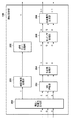
図1は、本発明の第1の実施形態に係るデジタルカメラ100の構成例を示すブロック図である。
図1において、レンズ群101は、フォーカスレンズを含むズームレンズである。絞り機能を備えるシャッター102が、レンズ群101と撮像部103との間に設けられている。撮像部103は、レンズ群101によって撮像面に形成される光学像を画素単位の電気信号に変換するCCD/CMOSイメージセンサを代表とする撮像素子を有する。A/D変換器104は、撮像部103が出力するアナログ信号をデジタル信号(画像データ)に変換する。
● (first embodiment)
FIG. 1 is a block diagram illustrating a configuration example of a
In FIG. 1, a
画像処理部105は、A/D変換器104から出力される画像データに対し、色補間(デモザイク)、ホワイトバランス調整、γ補正、輪郭強調、ノイズリダクション、色補正などの各種画像処理を行う。
The
画像メモリ106は画像データを一時的に記憶する。メモリ制御部107は、画像メモリ106の読み書きを制御する。D/A変換器108は、画像データをアナログ信号に変換する。表示部109はLCDや有機ELディスプレイ等の表示装置を有し、各種GUIやライブビュー画像、記録媒体112から読み出して再生した画像などを表示する。コーデック部110は、画像メモリ106に記憶されている画像データを記録媒体に記録するために予め定められた方法で符号化したり、画像ファイルに含まれる符号化画像データを例えば表示のために復号したりする。
The
インタフェース(I/F)111は、例えば半導体メモリカードやカード型ハードディスクなどの着脱可能な記録媒体112を、デジタルカメラ100と機械的および電気的に接続する。システム制御部50は例えばCPUやMPUなどのプログラマブルなプロセッサであってよい。システム制御部50は、例えば不揮発性メモリ121や内蔵する不揮発性メモリに記録されたプログラムを実行して必要なブロックや回路を制御することにより、デジタルカメラ100の機能を実現する。リライティング処理部114は、撮影画像に対して仮想光源による疑似照明効果を付与するリライティング処理を行う。
The interface (I / F) 111 mechanically and electrically connects a
距離情報生成部115は、画像メモリ106に格納された撮影画像データについて、画素ごとのコントラスト評価値や被写体輝度などを算出し、システム制御部50に供給する。また、距離情報生成部115は、撮影画像データから被写体の距離情報を取得し、例えば画素値が被写体距離を表すデプスマップを生成する。さらに距離情報生成部115は、リライティング処理を行う場合、処理対象の画像のデプスマップから、画素ごとの法線ベクトルを表す法線マップを生成し、リライティング処理部114に供給する。
The distance
操作部120は、ユーザがデジタルカメラ100に各種の指示を入力するためのボタンやスイッチなどをまとめて記載したものである。
The
不揮発性メモリ121は電気的に消去・記録可能な、例えばEEPROM等であってよい。不揮発性メモリ121は、各種の設定値、GUIデータをはじめ、システム制御部50がMPUやCPUである場合には、システム制御部50が実行するためのプログラムが記録される。
システムメモリ122は、システム制御部50の動作用の定数、変数、不揮発性メモリ121から読みだしたプログラム等を展開するために用いる。
The
The
次に、デジタルカメラ100における撮影時の動作について説明する。
例えば撮像部103は、シャッター102が開いている際にレンズ群101が撮像面に形成している被写体像を撮像素子によって光電変換し、アナログ画像信号としてA/D変換器104へ出力する。A/D変換器104は撮像部103から出力されるアナログ画像信号をデジタル画像信号(画像データ)に変換し画像処理部105に出力する。
Next, the operation at the time of shooting in the
For example, the
画像処理部105は、A/D変換器104からの画像データ、又は、メモリ制御部107からの画像データに対し、色補間(デモザイク)、γ補正、輪郭強調、ノイズリダクション、色補正などの各種画像処理を行う。画像処理部105ではさらに、撮影で得られた画像データを用いたオートホワイトバランス(AWB)調整も行う。
The
画像処理部105から出力された画像データは、メモリ制御部107を介して画像メモリ106に書き込まれる。画像メモリ106は、撮像部103から出力された画像データや、表示部109に表示するための画像データを格納する。
The image data output from the
距離情報生成部115は、画像メモリ106に格納された撮影画像データについて、画素ごとのコントラスト評価値や被写体輝度などを算出する。距離情報生成部115は、設定されている焦点検出領域についてのコントラスト評価値や、被写体輝度をシステム制御部50に供給する。システム制御部50はコントラスト評価値に基づいて自動焦点検出(AF)を実行したり、被写体輝度に基づいて自動露出制御(AE)を実行したりする。このように、本実施形態のデジタルカメラ100では、TTL(スルー・ザ・レンズ)方式のAF(オートフォーカス)処理、AE(自動露出)処理を行う。距離情報生成部115はさらに、撮影画像データから被写体の距離情報を取得し、例えば画素値が被写体距離を表すデプスマップを生成する。
The distance
また、D/A変換器108は、画像メモリ106に格納されている画像表示用のデータをアナログ信号に変換して表示部109に供給する。表示部109は、LCD等の表示装置に、D/A変換器108からのアナログ信号に応じた表示を行う。
The D /
コーデック部110は、画像メモリ106に記録された画像データをJPEGやMPEGなどの規格に基づき符号化する。システム制御部50は符号化した画像データに対して予め定められたヘッダなどを付与して画像ファイルを形成し、インタフェース111を介して記録媒体112に記録する。
The
なお、現在のデジタルカメラでは、撮影スタンバイ状態においては動画撮影を行い、撮影された動画を表示部109に表示し続けることにより表示部109を電子ビューファインダ(EVF)として機能させるのが一般的である。この場合、シャッター102は開いた状態とし、撮像部103のいわゆる電子シャッターを用いて例えば30フレーム/秒の撮影を行う。
Note that with current digital cameras, it is common to perform moving image shooting in the shooting standby state, and keep the captured moving image displayed on the
そして、操作部120に含まれるシャッターボタンが半押しされると上述のAF,AE制御が行われ、全押しされると本撮影により記録用の静止画撮影が実行され、記録媒体112に記録される。また、動画撮影ボタンなどにより動画撮影が指示された場合は、記録媒体112への動画記録を開始する。本実施形態においては、画像の記録時には、距離情報生成部115が生成した距離情報(デプスマップ)も対応付けて記録される。
When the shutter button included in the
なお、距離情報生成部115が距離情報を生成する方法に特に制限は無く、公知の方法を用いることができる。距離情報は画素ごとに被写体距離を表す情報であり、輝度値が距離を表すデプスマップ(距離画像、奥行き画像などと呼ばれることもある)であってよい。例えば、視差画像を用いずにデプスマップを生成する方法としては、上述したコントラスト評価値が極大となるフォーカスレンズ位置を画素ごとに求めることで、画素ごとに被写体距離を取得することができる。また、合焦距離を変えて同一シーンを複数回撮影して得られる画像データと光学系の点像分布関数(PSF)とから、ぼけ量と距離との相関関係に基づいて画素ごとの距離情報を求めることもできる。これらの技術に関しては例えば特開2010−177741号公報や米国特許第4,965,840号公報などに記載されている。また、視差画像対を取得可能な撮像素子を用いている場合には、ステレオマッチング等の手法で画素ごとに被写体距離を取得することができる。
In addition, there is no restriction | limiting in particular in the method in which the distance
また、デプスマップから画素ごとに被写体面の法線情報を生成する方法についても例えば特開2014−6658号公報に記載されるような公知の方法を用いることができる。法線情報は例えば、画素のRGB値が法線ベクトルの成分を表す法線マップの形式で生成することができる。デプスマップは撮影時(記録時)に生成する必要があるが、法線マップはデプスマップに基づいて生成可能であるため、リライティング処理時など、任意のタイミングで生成することができる。 Also, as a method for generating the normal information of the subject surface for each pixel from the depth map, a known method described in, for example, Japanese Patent Application Laid-Open No. 2014-6658 can be used. For example, the normal line information can be generated in the form of a normal map in which the RGB values of the pixels represent the components of the normal vector. The depth map needs to be generated at the time of shooting (recording). However, since the normal map can be generated based on the depth map, it can be generated at any timing such as during relighting processing.
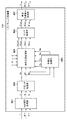
図2は画像処理部105の機能構成例を示すブロック図である。
図1のA/D変換器104から出力された画像データは、輝度・色信号生成部200に入力される。画像データは、撮像素子に設けられたカラーフィルタを構成する色成分の1つに対応した値を有する。一般的に用いられるベイヤー配列の原色カラーフィルタが用いられる場合、画像データは、R画素,G画素,B画素のデータから構成される。
FIG. 2 is a block diagram illustrating a functional configuration example of the
The image data output from the A /
輝度・色信号生成部200はこのような画像データに対してデモザイク処理を行って各画素が色信号R,G,Bを有するようにし、さらに色信号から輝度信号Yを生成する。輝度・色信号生成部200は、生成した色信号R,G,Bをホワイトバランス(WB)増幅部203へ、輝度信号Yを輪郭強調処理部201へ出力する。
The luminance / color
輪郭強調処理部201では、輝度信号Yに対して輪郭強調処理を行い、輝度ガンマ処理部202へ出力する。輝度ガンマ処理部202では輝度信号Yに対してガンマ補正を行い、補正後の輝度信号Yを画像メモリ106に出力する。
The contour
WB増幅部203は、後述する処理によりシステム制御部50が算出するホワイトバランスゲイン値に基づき、色信号R,G,Bにゲインを適用し、ホワイトバランスを調整する。色変換処理部204は、色信号R,G,Bに対するマトリクス演算などにより、所望のカラーバランスへ変換する。色ガンマ処理部205では、色信号R,G,Bにガンマ補正を行う。色差信号生成部206では、色信号R,G,Bから色差信号R−Y、B−Y信号を生成し、画像メモリ106に出力する。
The
画像メモリ106に出力された輝度信号Yと色差信号R−Y,B−Yが、コーデック部110によって符号化され、最終的に記録媒体112に記録される。
The luminance signal Y and the color difference signals RY and BY output to the
次に、リライティング処理部114の動作について説明する。
本実施形態では、リライティング処理の一例として、図3に示すような、人物700の顔の左側半分(図では右側半分)が影になっている画像に対して、ユーザの指示に基づいた仮想光源を照射し、影領域の明るさを補正することを想定している。
Next, the operation of the relighting
In the present embodiment, as an example of the relighting process, a virtual light source based on a user instruction is applied to an image in which the left half (right half in the figure) of the face of a person 700 is shaded as shown in FIG. It is assumed that the brightness of the shadow area is corrected.
次に、画像処理部105から出力された画像に対するリライティング処理について説明する。本実施形態において、リライティング処理は、システム制御部50が算出する制御パラメータを用いてリライティング処理部114が実行する。従って、まず、リライティング処理に用いる制御パラメータの算出および設定処理について図4(A)のフローチャートを用いて説明する。
Next, the relighting process for the image output from the
S501でシステム制御部50は、操作部120を通じてユーザからリライティング処理の指示を受け付ける。具体的にはシステム制御部50は、図示しないメニュー画面において、リライティング処理の実行に対応する項目を選択するユーザ操作を操作部120を通じて受け付ける。またシステム制御部50は、リライティング処理の実行指示とともに、例えばメニュー画面で指定されたリライティング処理のパラメータも受け付ける。
In step S <b> 501, the
リライティングのパラメータとしては本実施形態では説明の簡略化のため、仮想光源の位置、光源の強度(α)および光源の拡散特性(β)をユーザが入力するものとする(予め設定された選択肢から選択する方法でもよい)。仮想光源が被写体面を垂直に照射しているものとすると、仮想光源の位置が決まれば、仮想光源の光(仮想光)が最も強く当る位置(中心照射位置)も決まる。なお、仮想光源の位置は、仮想光源と例えば合焦距離に存在する主要被写体との位置関係を表す情報であってよい。 In this embodiment, the relighting parameters are assumed to be input by the user for the sake of simplification of description, the position of the virtual light source, the intensity (α) of the light source, and the diffusion characteristic (β) of the light source (from preset options). You can choose the method). Assuming that the virtual light source irradiates the subject surface vertically, if the position of the virtual light source is determined, the position (center irradiation position) where the light of the virtual light source (virtual light) is the strongest is also determined. Note that the position of the virtual light source may be information representing the positional relationship between the virtual light source and, for example, the main subject existing at the in-focus distance.
仮想光源の位置と、中心照射位置の例を図3に模式的に示す。図3には、仮想光源701の照射範囲703と中心照射位置702を示している。なお、本実施形態において仮想光源701からの仮想光は照射範囲703に対してのみ影響を与えるものとする。
An example of the position of the virtual light source and the center irradiation position is schematically shown in FIG. FIG. 3 shows the
S502でシステム制御部50は、ユーザから指示された光源の強度(α)および光源の拡散特性(β)を、制御パラメータとしてリライティング処理部114に設定する。
S503でシステム制御部50は、入力画像の画素ごとに、図3(b)に示すような中心照射位置702と対象画素704との距離Dを算出し、画素位置と対応付けてシステムメモリ122に格納する。なお、画素位置ごとの距離Dの情報は、制御パラメータとしてリライティング処理部114に設定してもよい。
In S502, the
In step S503, the
S504でシステム制御部50は、距離情報生成部115に、入力画像に対する法線マップを生成するよう指示する。距離情報生成部115は、入力画像のデータに対応付けて記録されているデプスマップから上述したような公知の方法で法線マップを生成し、システム制御部50へ供給する。システム制御部50は、法線マップをシステムメモリ122に格納する。なお、法線マップは制御パラメータとしてリライティング処理部114に設定してもよい。
S505でシステム制御部50は、リライティング処理部114にリライティング処理の実行を指示する。
In step S504, the
In step S505, the
次にリライティング処理部114の構成および動作の例について説明する。
図5はリライティング処理部114の構成を示すブロック図である。RGB信号変換部601は画像メモリ106から入力される、入力画像の処理対象画素の輝度および色差信号(Y,B−Y,R−Y)を、色信号(R,G,B)に変換する。デガンマ処理部602はデガンマ処理(輝度ガンマ処理部202および色ガンマ処理部205の逆処理)を行い、ガンマ補正前のリニアな特性の信号値に変換する。
Next, an example of the configuration and operation of the relighting
FIG. 5 is a block diagram showing a configuration of the relighting
平滑化処理部603はデガンマ処理部602の出力する色信号(R,G,B)を平滑化して仮想光源処理部604に出力する。仮想光源処理部604は仮想光によるライティング効果を画像に(対象画素ごとに)付加する。
ガンマ処理部606は仮想光源処理部604の出力する色信号(R,G,B)にガンマ補正を行う。輝度色差信号生成部607は、ガンマ補正後の色信号(R,G,B)を輝度および色差信号(Y,B−Y,R−Y)に変換し、画像メモリ106に出力する。
The smoothing
A
次にリライティング処理部114の動作について説明する。
リライティング処理部114は、画像メモリ106に記録された入力画像の、処理対象画素の輝度・色差信号(Y,B−Y,R−Y)を読み出す。RGB信号変換部601は、入力された輝度・色差信号(Y,B−Y,R−Y)をRGB信号に変換し、デガンマ処理部602へ出力する。
Next, the operation of the relighting
The relighting
デガンマ処理部602は、画像処理部105の輝度ガンマ処理部202および色ガンマ処理部205で適用されたガンマ特性と逆の特性の演算を行い、ガンマ補正前のリニアな特性における信号値(Rt,Gt,Bt)に変換する。デガンマ処理部602は、変換後の画素信号を、平滑化処理部603および仮想光源処理部604へ出力する。なお、デガンマ処理部602をRGB信号変換部601の前段に配置してデガンマ処理を行ってもよい。例えば、Y信号に対しては輝度ガンマ処理部202と逆の処理を適用し、色差信号R−Y,B−YについてはRGB信号に戻してから色ガンマ処理部205と逆の処理を適用し、色差信号R−Y,B−Yに再変換してからRGB信号変換部601に入力する。
The
平滑化処理部603は、仮想光源の拡散特性(β)を考慮して光源反射色成分を平滑化する関数fを用いて、処理対象の画素信号(Rt,Gt,Bt)を、色成分ごとに平滑化する。一例として、本実施形態では、関数fを、仮想光源の拡散特性(β)を標準偏差とするガウス関数とし、このガウス関数を近似する1次元または2次元ガウシアンフィルタを画素の信号値に適用することにより平滑化を行う。拡散特性(β)が大きく、仮想光の拡散度合いが大きいほど、光源反射色成分の信号が平滑化される。平滑化処理部603は、平滑化した画素信号(Ra,Ga,Ba)を仮想光源処理部604へ出力する。平滑化処理で得られる画素信号(Ra,Ga,Ba)は、処理対象画素の近傍における環境光の反射特性を表し、仮想光の反射成分を算出する際に用いられる。
The smoothing
平滑化処理部603はさらに、平滑化処理で得られる画素信号(Ra,Ga,Ba)に、例えば、画像のエッジ部に対応した特定の周波数成分を抽出する2次元フィルタを適用して輪郭補償信号を生成する。そして、色成分から輝度値を振幅値f(Mt(x,y),β)=Maとして算出し、仮想光源処理部604へ出力する。
The smoothing
仮想光源処理部604は、仮想光によるリライティングの効果を入力画像に付加するための補正信号の生成と、補正信号を用いた補正処理とを行う。
具体的には、デガンマ処理部602から出力される画素信号(Rt,Gt,Bt)に対し、
・平滑化処理部603から出力される平滑化後の画素信号(Ra,Ga,Ba)と、
・システム制御部50から入力される、制御パラメータ(仮想光源の位置情報、仮想光源の強度(α)、仮想光源の拡散特性(β)、仮想光源の中心照射位置からの距離(D)、被写体の3次元形状情報(被写体面の法線情報(N)))と
から、仮想光を照射した場合の反射色成分(Rv,Gv,Bv)を推定する。
The virtual light
Specifically, for the pixel signal (Rt, Gt, Bt) output from the
A smoothed pixel signal (Ra, Ga, Ba) output from the smoothing
Control parameters (virtual light source position information, virtual light source intensity (α), virtual light source diffusion characteristics (β), distance from the center irradiation position of the virtual light source (D), subject input from the
仮想光源処理部604は、反射色成分(Rv,Gv,Bv)を例えば以下の式によって求める。

仮想光源処理部604は、推定した反射色成分(Rv,Gv,Bv)を、デガンマ処理部602から出力される画素信号(Rt,Gt,Bt)に加算し、仮想光源によるリライティング効果を処理対象画素に付与する。すなわち、仮想光源処理部604は、以下の式(4)〜(6)の演算により、処理後の画素信号(Rout,Gout,Bout)を生成し、ガンマ処理部606に出力する。
Rout(x,y) = Rt(x,y) + Rv(x,y) 式(4)
Gout(x,y) = Gt(x,y) + Gv(x,y) 式(5)
Bout(x,y) = Bt(x,y) + Bv(x,y) 式(6)
The virtual light
Rout (x, y) = Rt (x, y) + Rv (x, y) Equation (4)
Gout (x, y) = Gt (x, y) + Gv (x, y) Equation (5)
Bout (x, y) = Bt (x, y) + Bv (x, y) Equation (6)
さらに仮想光源処理部604は、デガンマ処理部602から出力される画素信号(Rt,Gt,Bt)について、例えば、画像のエッジ部に対応した特定の周波数成分を抽出する2次元フィルタを適用することにより輪郭補償信号ACt(x,y)を生成する。そして仮想光源処理部604は輪郭補償信号ACt(x,y)に対し、仮想光源の拡散特性に応じた補正を適用することで、仮想光源の特性を反映しつつ、リライティング処理によって低下する鮮鋭度を補正するための輪郭補償信号ACout(x,y)を生成する。
Further, the virtual light
ここで、本実施形態における、仮想光源の拡散特性を考慮した輪郭補償について説明する。一般に、ディフューザーを用いる等により拡散した照明光で撮影した場合、反射光の強度が弱いためエッジ部の振幅も小さく、鮮鋭度の低い画像が得られる。一方、ベアバルブ撮影のような直進性の高い照明光で撮影した場合、反射光の強度が強いためエッジ部の振幅も大きく、鮮鋭度の高い画像が得られる。 Here, the contour compensation in consideration of the diffusion characteristic of the virtual light source in this embodiment will be described. In general, when photographing with illumination light diffused by using a diffuser or the like, the intensity of reflected light is weak, so that the amplitude of the edge portion is small and an image with low sharpness is obtained. On the other hand, when photographing with illumination light having high straightness such as bare bulb photographing, the intensity of the reflected light is strong, so that the amplitude of the edge portion is large and an image with high sharpness can be obtained.
そのため、本実施形態では、リライティング処理において用いる仮想光源の拡散特性(β)を考慮して輪郭補正することで、より自然なリライティング効果を付与する。つまり、拡散度の高い特性を有する仮想光源を用いる場合にはエッジ部の振幅が小さくなるように輪郭補償を行い、拡散度の低い(直進性の高い)特性を有する仮想光源を用いる場合にはエッジ部の振幅が大きくなるように輪郭補償を行う。 For this reason, in the present embodiment, a more natural relighting effect is given by correcting the contour in consideration of the diffusion characteristic (β) of the virtual light source used in the relighting process. In other words, when using a virtual light source having a high diffusivity characteristic, contour compensation is performed so that the amplitude of the edge portion becomes small, and when using a virtual light source having a low diffusivity characteristic (high straightness) Contour compensation is performed so that the amplitude of the edge portion is increased.
本実施形態で仮想光源処理部604は、画素位置(x,y)における輪郭補償信号の振幅の大きさMv(x,y)を、以下の式(7)によって求める。
そして、仮想光源処理部604は、輪郭補償信号ACt(x,y)に対して、仮想光源の特性を反映させた輪郭補償信号ACout(x,y)を、以下の式(8)に従って求める。
ACout(x,y) = ACt(x,y) × Mv(x,y)/Mt(x,y) 式(8)
式(8)において、Mt(x,y)は、ACt(x,y)の振幅の大きさであり、例えば輝度値である。
Then, the virtual light
ACout (x, y) = ACt (x, y) x Mv (x, y) / Mt (x, y) Equation (8)
In Equation (8), Mt (x, y) is the magnitude of the amplitude of ACt (x, y), for example, a luminance value.
式(8)の処理により、設定された仮想光源の拡散特性βが大きいほど(仮想光の拡散度が高いほど)、輪郭強調が弱くなり、拡散特性βが小さいほど(仮想光の拡散度が低いほど)、輪郭強調が強くなるような輪郭補償信号が生成される。 As a result of the processing of Expression (8), the larger the diffusion characteristic β of the set virtual light source (the higher the diffusion degree of the virtual light), the weaker the edge enhancement, and the smaller the diffusion characteristic β (the diffusion degree of the virtual light). The contour compensation signal is generated so that the contour enhancement becomes stronger as the value is lower.
なお、本実施形態では、輪郭補償時の振幅制御を例に、仮想光源の拡散特性に応じた鮮鋭度の調整を実現する場合について説明した。しかし、本質は、画像の鮮鋭度を調整するための処理のパラメータを仮想光源の拡散特性(仮想光の拡散度もしくは直進性)に応じて制御することであって、振幅制御以外のパラメータに対する制御であってもよい。すなわち、画像の鮮鋭度を調整するための処理のパラメータを仮想光源の拡散特性(仮想光の拡散度もしくは直進性)に応じて制御する方法は、上記の例に限定されない。 In the present embodiment, the case of realizing the sharpness adjustment according to the diffusion characteristic of the virtual light source has been described by taking the amplitude control at the time of contour compensation as an example. However, the essence is to control the processing parameters for adjusting the sharpness of the image according to the diffusion characteristics (virtual light diffusion degree or straightness) of the virtual light source, and control over parameters other than amplitude control. It may be. In other words, the method for controlling the processing parameter for adjusting the sharpness of the image according to the diffusion characteristic of the virtual light source (the diffusion degree or straightness of the virtual light) is not limited to the above example.
次に、図4(B)のフローチャートを用い、上述した、リライティング処理部114におけるリライティング効果付与処理動作、特に平滑化処理部603および仮想光源処理部604、ガンマ処理部606の動作について詳細に説明する。
入力画像に対するリライティング効果の付与は画素単位で行うため、以下に説明する動作は、特に説明しない限り処理対象の画素(着目画素)に対して行われる。ただし、空間フィルタリング処理のように、着目画素の周辺画素値が必要な処理については、これら処理対象画素以外の画素も処理に用いられる。
Next, the above-described relighting effect imparting processing operation in the relighting
Since the relighting effect is applied to the input image in units of pixels, the operation described below is performed on the pixel to be processed (target pixel) unless otherwise specified. However, for a process that requires a peripheral pixel value of the pixel of interest, such as a spatial filtering process, pixels other than these process target pixels are also used in the process.
S510で仮想光源処理部604は、着目画素が仮想光源の照射範囲内に位置するかどうかを判定する。本実施形態では、S503(図4(A))においてシステム制御部50が画素ごとに中心照射位置702(図3(a))からの距離Dを算出している。そのため、仮想光源処理部604は、着目画素の距離Dが、仮想光源の拡散特性や仮想光源と被写体との距離などに応じて定まる閾値以下であれば照射範囲内と判定して処理をS511へ進め、閾値より大きければ照射範囲外と判定し、処理を終了する。
In step S510, the virtual light
S511では、平滑化処理部603および仮想光源処理部604により、仮想光の反射色成分(Rv,Gv,Bv)と、輪郭補償信号ACtを生成する。具体的には、以下の処理を行う。
・平滑化処理部603が、着目画素の信号(Rt,Gt,Bt)を平滑化し、平滑化後の画素信号(Ra,Ga,Ba)を仮想光源処理部604へ出力する。
・仮想光源処理部604が、平滑化処理部603から入力される平滑化後の画素信号(Ra,Ga,Ba)と、システム制御部50から入力される制御パラメータとから、着目画素における仮想光の反射色成分(Rv,Gv,Bv)を算出する。
なお、制御パラメータは、仮想光源の位置情報、仮想光源の強度(α)、仮想光源の拡散特性(β)、仮想光源の中心照射位置からの距離(D)、被写体の3次元形状情報(N)である。
・仮想光源処理部604が、着目画素の信号(Rt,Gt,Bt)から輪郭補償信号ACtを生成する。
In S511, the smoothing
The smoothing
The virtual light
The control parameters include the position information of the virtual light source, the intensity (α) of the virtual light source, the diffusion characteristic (β) of the virtual light source, the distance (D) from the central irradiation position of the virtual light source, and the three-dimensional shape information (N ).
The virtual light
S512で仮想光源処理部604は、S511で求めた仮想光の反射色成分(Rv,Gv,Bv)を、着目画素の信号(Rt,Gt,Bt)に加算し、仮想光によるリライティング効果を付加する。そして、仮想光源処理部604は、リライティング効果を付加した画素信号(Rout,Gout,Bout)をガンマ処理部606に出力する。
In S512, the virtual light
S513では、仮想光源処理部604が輪郭補償信号ACtを仮想光源の拡散特性に基づいて補正し、補正後の輪郭補償信号ACoutを生成して、ガンマ処理部606に出力する。具体的には以下の処理を行う。
・平滑化処理部603が、平滑化後の画素信号(Ra,Ga,Ba)から輪郭補償信号を生成し、その振幅値Ma(=f(Mt(x,y),β))を算出して仮想光源処理部604へ出力する。
・仮想光源処理部604が、輪郭補償信号ACtとその振幅値Mtと、平滑化処理部603から入力されるMaに仮想光の拡散特性を反映させたMvとから、補正後の輪郭補償信号ACoutを生成する。
In step S <b> 513, the virtual light
The smoothing
The virtual light
S515でガンマ処理部606は、仮想光源処理部604から出力された画素信号(Rout,Gout,Bout)に、輪郭補償信号ACoutを参照して輪郭補償を行い、リライティング処理による解像感の低下を補う。その後、ガンマ処理部606は所定のガンマ補正を適用し、画素信号(R’out,G’out,B’out)を輝度色差信号生成部607へ出力する。輝度色差信号生成部607では、画素信号(R’out,G’out,B’out)から輝度信号Yおよび、色差信号R−Y、B−Y信号を生成して出力する。以上の処理により、補正対象の画素についての処理が完了する。上述の処理を、入力画像の各画素に対して適用する。
S51 5
システム制御部50は、リライティング処理部114が出力した輝度および色差信号を、メモリ制御部107の制御によって、画像メモリ106に蓄積する。そして、システム制御部50は、入力画像全体に対してリライティング処理が終了すると、コーデック部110を用いて圧縮符号化を行い、I/F111を介して記録媒体112に記録する。
The
以上説明したように、本実施形態では仮想光源を設定してリライティング効果を付加した画像に対して輪郭補償することにより、リライティング効果の付加によって低下する鮮鋭度を補正することができる。特に、仮想光の拡散度を考慮した輪郭補償を行うことにより、仮想光源の特性に対応した輪郭補正が実現でき、好適な画質が得られる。 As described above, in the present embodiment, the sharpness that decreases due to the addition of the relighting effect can be corrected by performing contour compensation on the image to which the relighting effect is added by setting the virtual light source. In particular, by performing contour compensation in consideration of the diffusion degree of virtual light, contour correction corresponding to the characteristics of the virtual light source can be realized, and a suitable image quality can be obtained.
例えば、仮想光の拡散度が大きい場合には、拡散度が小さい場合よりも輪郭補償の強度が弱くなり、逆に仮想光の拡散度が小さい場合には輪郭補償の強度が強くなるため、仮想光の特性とマッチした鮮鋭度の補正を実現できる。 For example, when the diffusivity of virtual light is large, the strength of contour compensation is weaker than when the diffusivity is small, and conversely, when the diffusivity of virtual light is small, the strength of contour compensation is high. Sharpness correction that matches the characteristics of light can be realized.
なお、本実施形態では、仮想光の照射範囲に存在する被写体が人物である場合を例に説明したが、他の被写体であってもよい。また、本実施形態では、仮想光源の照射範囲の画素を明るく補正するリライティング処理について説明したが、暗く補正する場合でも同様に適用できる。また、仮想光の色反射成分(Rv,Gv,Bv)の算出方法は、本実施形態の形態で説明した方法に限らず、他の方法で算出してもよい。 In the present embodiment, the case where the subject existing in the virtual light irradiation range is a person has been described as an example, but another subject may be used. In the present embodiment, the relighting process for correcting brightly the pixels in the irradiation range of the virtual light source has been described. However, the present invention can be similarly applied even when correcting darkly. Further, the calculation method of the color reflection components (Rv, Gv, Bv) of the virtual light is not limited to the method described in the embodiment, and may be calculated by other methods.
また、輪郭補償信号の振幅を仮想光源の照射特性に応じて制御する際、制御係数が着目画素と中心照射位置との距離Dの2乗に反比例するようにしたが、例えば、距離Dに反比例させたり、ガウス分布的に強度が変化するようにしたりしてもよい。 Further, when controlling the amplitude of the contour compensation signal in accordance with the irradiation characteristics of the virtual light source, the control coefficient is inversely proportional to the square of the distance D between the target pixel and the central irradiation position. For example, the control coefficient is inversely proportional to the distance D. The intensity may be changed in a Gaussian distribution.
(その他の実施形態)
また、本発明は、以下の処理を実行することによっても実現される。即ち、上述した実施形態の機能を実現するソフトウェア(プログラム)を、ネットワーク又は各種記憶媒体を介してシステム或いは装置に供給し、そのシステム或いは装置のコンピュータ(またはCPUやMPU等)がプログラムを読み出して実行する処理である。
(Other embodiments)
The present invention can also be realized by executing the following processing. That is, software (program) that realizes the functions of the above-described embodiments is supplied to a system or apparatus via a network or various storage media, and a computer (or CPU, MPU, etc.) of the system or apparatus reads the program. It is a process to be executed.
50…システム制御部,101…光学系,102…シャッター,103…撮像部,104…A/D変換器,105…画像処理部,106…画像メモリ,107…メモリ制御部,109…表示部,110…コーデック部,111…記録I/F,112…記録媒体,113…顔検出部,114…リライティング処理部,120…操作部,121…不揮発性メモリ,122…システムメモリ
DESCRIPTION OF
Claims (13)
画像の、前記仮想光の照射範囲に含まれる画素の明るさを補正する明るさ補正手段と、
前記画像の前記照射範囲内の鮮鋭度を補正する鮮鋭度補正手段とを有し、
前記鮮鋭度補正手段は、前記仮想光の拡散度合いが第1の度合いよりも小さい第2の度合いである場合、前記第1の度合いである場合よりも前記鮮鋭度が強くなるように補正することを特徴とする画像処理装置。 An image processing apparatus that corrects image brightness using virtual light,
And brightness correction means for correcting the image, the brightness of the pixels included in the irradiation range of the virtual light,
And a sharpness accessory Seite stage for correcting the sharpness within the irradiation range of the previous SL image,
The sharpness correction means corrects the sharpness to be stronger when the virtual light diffusion degree is a second degree smaller than the first degree than when the virtual light is diffused. An image processing apparatus.
前記平滑化手段は、前記仮想光の拡散度合いが大きいほど、平滑化の度合いを強くすることを特徴とする請求項1乃至3のいずれか1項に記載の画像処理装置。 The image processing apparatus according to claim 1, wherein the smoothing unit increases the degree of smoothing as the degree of diffusion of the virtual light increases.
前記明るさ補正手段は、前記推定された反射色成分を前記仮想光の照射範囲に含まれる画素に反映させることにより、前記仮想光の照射範囲に含まれる画素の明るさを補正することを特徴とする請求項1から5のいずれか1項に記載の画像処理装置。 An estimation unit that estimates a reflection color component of the virtual light in pixels included in the irradiation range of the virtual light;
The brightness correction unit corrects the brightness of pixels included in the virtual light irradiation range by reflecting the estimated reflected color component on the pixels included in the virtual light irradiation range. The image processing apparatus according to any one of claims 1 to 5 .
前記推定手段により推定される前記仮想光の反射色成分は、前記仮想光の強度に依存することを特徴とする請求項6に記載の画像処理装置。 The image processing apparatus according to claim 6, wherein the reflected color component of the virtual light estimated by the estimation unit depends on the intensity of the virtual light.
前記明るさ補正手段は、前記撮像手段により撮像を行うことによって得られた画像の、前記仮想光の照射範囲に含まれる画素の明るさを補正することを特徴とする請求項1から10のいずれか1項に記載の画像処理装置。 It further has an imaging means,
The brightness correction means, the image obtained by performing image pickup by the image pickup means, any of claims 1 to 10, characterized in that to correct the brightness of the pixels included in the irradiation range of the virtual light The image processing apparatus according to claim 1.
補正手段が、画像の、前記仮想光の照射範囲に含まれる画素の明るさを補正する明るさ補正工程と、
鮮鋭度補正手段が、前記画像の前記照射範囲内の鮮鋭度を補正する鮮鋭度補正工程と、を有し、
前記鮮鋭度補正工程では、前記仮想光の拡散度合いが第1の度合いよりも小さい第2の度合いである場合、前記第1の度合いである場合よりも前記鮮鋭度が強くなるように補正することを特徴とする画像処理装置の制御方法。 A control method for an image processing apparatus that corrects the brightness of an image using virtual light,
Correction means, and brightness correction step of correcting the brightness of the pixels included in the image, the illumination range of the virtual light,
Sharpness correction means has a higher sharpness complement Seiko for correcting the sharpness within the irradiation range of the previous SL image and,
In the sharpness correction step, when the degree of diffusion of the virtual light is a second degree smaller than the first degree, the sharpness is corrected so as to be stronger than when the degree is the first degree. A method for controlling an image processing apparatus.
Priority Applications (2)
| Application Number | Priority Date | Filing Date | Title |
|---|---|---|---|
| JP2015048494A JP6463177B2 (en) | 2015-03-11 | 2015-03-11 | Image processing apparatus and control method thereof |
| US15/066,715 US9961319B2 (en) | 2015-03-11 | 2016-03-10 | Image processing apparatus and control method thereof |
Applications Claiming Priority (1)
| Application Number | Priority Date | Filing Date | Title |
|---|---|---|---|
| JP2015048494A JP6463177B2 (en) | 2015-03-11 | 2015-03-11 | Image processing apparatus and control method thereof |
Publications (3)
| Publication Number | Publication Date |
|---|---|
| JP2016171391A JP2016171391A (en) | 2016-09-23 |
| JP2016171391A5 JP2016171391A5 (en) | 2018-04-19 |
| JP6463177B2 true JP6463177B2 (en) | 2019-01-30 |
Family
ID=56886974
Family Applications (1)
| Application Number | Title | Priority Date | Filing Date |
|---|---|---|---|
| JP2015048494A Active JP6463177B2 (en) | 2015-03-11 | 2015-03-11 | Image processing apparatus and control method thereof |
Country Status (2)
| Country | Link |
|---|---|
| US (1) | US9961319B2 (en) |
| JP (1) | JP6463177B2 (en) |
Families Citing this family (7)
| Publication number | Priority date | Publication date | Assignee | Title |
|---|---|---|---|---|
| US9922452B2 (en) * | 2015-09-17 | 2018-03-20 | Samsung Electronics Co., Ltd. | Apparatus and method for adjusting brightness of image |
| JP6742231B2 (en) * | 2016-12-09 | 2020-08-19 | キヤノン株式会社 | Image processing apparatus and method, and imaging apparatus |
| US10740954B2 (en) | 2018-03-17 | 2020-08-11 | Nvidia Corporation | Shadow denoising in ray-tracing applications |
| JP7059076B2 (en) * | 2018-03-30 | 2022-04-25 | キヤノン株式会社 | Image processing device, its control method, program, recording medium |
| JP7199849B2 (en) * | 2018-06-27 | 2023-01-06 | キヤノン株式会社 | Image processing device, image processing method, and program |
| US10991079B2 (en) | 2018-08-14 | 2021-04-27 | Nvidia Corporation | Using previously rendered scene frames to reduce pixel noise |
| US10916051B2 (en) * | 2019-07-08 | 2021-02-09 | Google Llc | Video lighting using depth and virtual lights |
Family Cites Families (12)
| Publication number | Priority date | Publication date | Assignee | Title |
|---|---|---|---|---|
| US4965840A (en) | 1987-11-27 | 1990-10-23 | State University Of New York | Method and apparatus for determining the distances between surface-patches of a three-dimensional spatial scene and a camera system |
| JP5088220B2 (en) * | 2008-04-24 | 2012-12-05 | カシオ計算機株式会社 | Image generating apparatus and program |
| JP5158202B2 (en) * | 2008-08-19 | 2013-03-06 | 富士通株式会社 | Image correction apparatus and image correction method |
| JP5237066B2 (en) * | 2008-11-28 | 2013-07-17 | キヤノン株式会社 | Mixed reality presentation system, mixed reality presentation method, and program |
| JP5281878B2 (en) | 2008-12-03 | 2013-09-04 | オリンパスイメージング株式会社 | IMAGING DEVICE, LIGHTING PROCESSING DEVICE, LIGHTING PROCESSING METHOD, AND LIGHTING PROCESSING PROGRAM |
| IL196161A (en) * | 2008-12-24 | 2015-03-31 | Rafael Advanced Defense Sys | Removal of shadows from images in a video signal |
| JP5178553B2 (en) | 2009-01-27 | 2013-04-10 | オリンパス株式会社 | Imaging device |
| JP5235805B2 (en) * | 2009-07-13 | 2013-07-10 | キヤノン株式会社 | Color processing method, color processing apparatus, and program |
| JP2012194756A (en) * | 2011-03-16 | 2012-10-11 | Mitsubishi Electric Corp | Display device and navigation device |
| JP5795556B2 (en) | 2012-06-22 | 2015-10-14 | 日本電信電話株式会社 | Shadow information deriving device, shadow information deriving method and program |
| US9483815B2 (en) * | 2013-10-23 | 2016-11-01 | Cornell University | Systems and methods for computational lighting |
| JP2015184952A (en) * | 2014-03-25 | 2015-10-22 | ソニー株式会社 | Image processing device, image processing method, and program |
-
2015
- 2015-03-11 JP JP2015048494A patent/JP6463177B2/en active Active
-
2016
- 2016-03-10 US US15/066,715 patent/US9961319B2/en active Active
Also Published As
| Publication number | Publication date |
|---|---|
| US20160269705A1 (en) | 2016-09-15 |
| JP2016171391A (en) | 2016-09-23 |
| US9961319B2 (en) | 2018-05-01 |
Similar Documents
| Publication | Publication Date | Title |
|---|---|---|
| JP6463177B2 (en) | Image processing apparatus and control method thereof | |
| JP6445844B2 (en) | Imaging device and method performed in imaging device | |
| US10574961B2 (en) | Image processing apparatus and image processing method thereof | |
| JP6442209B2 (en) | Image processing apparatus and control method thereof | |
| US10861136B2 (en) | Image processing apparatus, image processing method, and storage medium | |
| JP6006543B2 (en) | Image processing apparatus and image processing method | |
| JP2016086246A (en) | Image processing apparatus and method, and imaging device | |
| JP6742231B2 (en) | Image processing apparatus and method, and imaging apparatus | |
| JP2010183460A (en) | Image capturing apparatus and method of controlling the same | |
| JP6541416B2 (en) | IMAGE PROCESSING APPARATUS, IMAGE PROCESSING METHOD, PROGRAM, AND STORAGE MEDIUM | |
| US10021314B2 (en) | Image processing apparatus, image capturing apparatus, method of controlling the same, and storage medium for changing shading using a virtual light source | |
| JP2010183461A (en) | Image capturing apparatus and method of controlling the same | |
| JP6663246B2 (en) | Image processing apparatus, imaging apparatus, control method thereof, and program | |
| JP6701299B2 (en) | Image processing apparatus and image processing method | |
| JP2017182668A (en) | Data processor, imaging device, and data processing method | |
| JP5789330B2 (en) | Imaging apparatus and control method thereof | |
| JP2024071082A (en) | Imaging device and control method thereof, and program | |
| JP2021087125A (en) | Image processing device, control method thereof, and program | |
| JP2019037004A (en) | Image processing apparatus, control method thereof, and program | |
| JP2018041203A (en) | Image processor, image processing method, and program |
Legal Events
| Date | Code | Title | Description |
|---|---|---|---|
| A521 | Request for written amendment filed |
Free format text: JAPANESE INTERMEDIATE CODE: A523 Effective date: 20180309 |
|
| A621 | Written request for application examination |
Free format text: JAPANESE INTERMEDIATE CODE: A621 Effective date: 20180309 |
|
| A977 | Report on retrieval |
Free format text: JAPANESE INTERMEDIATE CODE: A971007 Effective date: 20181119 |
|
| TRDD | Decision of grant or rejection written | ||
| A01 | Written decision to grant a patent or to grant a registration (utility model) |
Free format text: JAPANESE INTERMEDIATE CODE: A01 Effective date: 20181203 |
|
| A61 | First payment of annual fees (during grant procedure) |
Free format text: JAPANESE INTERMEDIATE CODE: A61 Effective date: 20181228 |
|
| R151 | Written notification of patent or utility model registration |
Ref document number: 6463177 Country of ref document: JP Free format text: JAPANESE INTERMEDIATE CODE: R151 |