JP6717826B2 - Electric power supply and energy harvesting auxiliary system for electric vehicle and method of operating the power supply and energy harvesting auxiliary system - Google Patents
Electric power supply and energy harvesting auxiliary system for electric vehicle and method of operating the power supply and energy harvesting auxiliary system Download PDFInfo
- Publication number
- JP6717826B2 JP6717826B2 JP2017528512A JP2017528512A JP6717826B2 JP 6717826 B2 JP6717826 B2 JP 6717826B2 JP 2017528512 A JP2017528512 A JP 2017528512A JP 2017528512 A JP2017528512 A JP 2017528512A JP 6717826 B2 JP6717826 B2 JP 6717826B2
- Authority
- JP
- Japan
- Prior art keywords
- power supply
- voltage
- operating state
- drive chain
- battery assembly
- Prior art date
- Legal status (The legal status is an assumption and is not a legal conclusion. Google has not performed a legal analysis and makes no representation as to the accuracy of the status listed.)
- Active
Links
Images


Classifications
-
- B—PERFORMING OPERATIONS; TRANSPORTING
- B60—VEHICLES IN GENERAL
- B60L—PROPULSION OF ELECTRICALLY-PROPELLED VEHICLES; SUPPLYING ELECTRIC POWER FOR AUXILIARY EQUIPMENT OF ELECTRICALLY-PROPELLED VEHICLES; ELECTRODYNAMIC BRAKE SYSTEMS FOR VEHICLES IN GENERAL; MAGNETIC SUSPENSION OR LEVITATION FOR VEHICLES; MONITORING OPERATING VARIABLES OF ELECTRICALLY-PROPELLED VEHICLES; ELECTRIC SAFETY DEVICES FOR ELECTRICALLY-PROPELLED VEHICLES
- B60L53/00—Methods of charging batteries, specially adapted for electric vehicles; Charging stations or on-board charging equipment therefor; Exchange of energy storage elements in electric vehicles
- B60L53/50—Charging stations characterised by energy-storage or power-generation means
-
- B—PERFORMING OPERATIONS; TRANSPORTING
- B60—VEHICLES IN GENERAL
- B60L—PROPULSION OF ELECTRICALLY-PROPELLED VEHICLES; SUPPLYING ELECTRIC POWER FOR AUXILIARY EQUIPMENT OF ELECTRICALLY-PROPELLED VEHICLES; ELECTRODYNAMIC BRAKE SYSTEMS FOR VEHICLES IN GENERAL; MAGNETIC SUSPENSION OR LEVITATION FOR VEHICLES; MONITORING OPERATING VARIABLES OF ELECTRICALLY-PROPELLED VEHICLES; ELECTRIC SAFETY DEVICES FOR ELECTRICALLY-PROPELLED VEHICLES
- B60L15/00—Methods, circuits, or devices for controlling the traction-motor speed of electrically-propelled vehicles
- B60L15/20—Methods, circuits, or devices for controlling the traction-motor speed of electrically-propelled vehicles for control of the vehicle or its driving motor to achieve a desired performance, e.g. speed, torque, programmed variation of speed
- B60L15/2045—Methods, circuits, or devices for controlling the traction-motor speed of electrically-propelled vehicles for control of the vehicle or its driving motor to achieve a desired performance, e.g. speed, torque, programmed variation of speed for optimising the use of energy
-
- B—PERFORMING OPERATIONS; TRANSPORTING
- B60—VEHICLES IN GENERAL
- B60L—PROPULSION OF ELECTRICALLY-PROPELLED VEHICLES; SUPPLYING ELECTRIC POWER FOR AUXILIARY EQUIPMENT OF ELECTRICALLY-PROPELLED VEHICLES; ELECTRODYNAMIC BRAKE SYSTEMS FOR VEHICLES IN GENERAL; MAGNETIC SUSPENSION OR LEVITATION FOR VEHICLES; MONITORING OPERATING VARIABLES OF ELECTRICALLY-PROPELLED VEHICLES; ELECTRIC SAFETY DEVICES FOR ELECTRICALLY-PROPELLED VEHICLES
- B60L50/00—Electric propulsion with power supplied within the vehicle
- B60L50/50—Electric propulsion with power supplied within the vehicle using propulsion power supplied by batteries or fuel cells
- B60L50/53—Electric propulsion with power supplied within the vehicle using propulsion power supplied by batteries or fuel cells in combination with an external power supply, e.g. from overhead contact lines
-
- B—PERFORMING OPERATIONS; TRANSPORTING
- B60—VEHICLES IN GENERAL
- B60L—PROPULSION OF ELECTRICALLY-PROPELLED VEHICLES; SUPPLYING ELECTRIC POWER FOR AUXILIARY EQUIPMENT OF ELECTRICALLY-PROPELLED VEHICLES; ELECTRODYNAMIC BRAKE SYSTEMS FOR VEHICLES IN GENERAL; MAGNETIC SUSPENSION OR LEVITATION FOR VEHICLES; MONITORING OPERATING VARIABLES OF ELECTRICALLY-PROPELLED VEHICLES; ELECTRIC SAFETY DEVICES FOR ELECTRICALLY-PROPELLED VEHICLES
- B60L53/00—Methods of charging batteries, specially adapted for electric vehicles; Charging stations or on-board charging equipment therefor; Exchange of energy storage elements in electric vehicles
-
- B—PERFORMING OPERATIONS; TRANSPORTING
- B60—VEHICLES IN GENERAL
- B60L—PROPULSION OF ELECTRICALLY-PROPELLED VEHICLES; SUPPLYING ELECTRIC POWER FOR AUXILIARY EQUIPMENT OF ELECTRICALLY-PROPELLED VEHICLES; ELECTRODYNAMIC BRAKE SYSTEMS FOR VEHICLES IN GENERAL; MAGNETIC SUSPENSION OR LEVITATION FOR VEHICLES; MONITORING OPERATING VARIABLES OF ELECTRICALLY-PROPELLED VEHICLES; ELECTRIC SAFETY DEVICES FOR ELECTRICALLY-PROPELLED VEHICLES
- B60L7/00—Electrodynamic brake systems for vehicles in general
- B60L7/10—Dynamic electric regenerative braking
- B60L7/12—Dynamic electric regenerative braking for vehicles propelled by dc motors
-
- B—PERFORMING OPERATIONS; TRANSPORTING
- B60—VEHICLES IN GENERAL
- B60L—PROPULSION OF ELECTRICALLY-PROPELLED VEHICLES; SUPPLYING ELECTRIC POWER FOR AUXILIARY EQUIPMENT OF ELECTRICALLY-PROPELLED VEHICLES; ELECTRODYNAMIC BRAKE SYSTEMS FOR VEHICLES IN GENERAL; MAGNETIC SUSPENSION OR LEVITATION FOR VEHICLES; MONITORING OPERATING VARIABLES OF ELECTRICALLY-PROPELLED VEHICLES; ELECTRIC SAFETY DEVICES FOR ELECTRICALLY-PROPELLED VEHICLES
- B60L7/00—Electrodynamic brake systems for vehicles in general
- B60L7/10—Dynamic electric regenerative braking
- B60L7/14—Dynamic electric regenerative braking for vehicles propelled by ac motors
-
- B—PERFORMING OPERATIONS; TRANSPORTING
- B60—VEHICLES IN GENERAL
- B60L—PROPULSION OF ELECTRICALLY-PROPELLED VEHICLES; SUPPLYING ELECTRIC POWER FOR AUXILIARY EQUIPMENT OF ELECTRICALLY-PROPELLED VEHICLES; ELECTRODYNAMIC BRAKE SYSTEMS FOR VEHICLES IN GENERAL; MAGNETIC SUSPENSION OR LEVITATION FOR VEHICLES; MONITORING OPERATING VARIABLES OF ELECTRICALLY-PROPELLED VEHICLES; ELECTRIC SAFETY DEVICES FOR ELECTRICALLY-PROPELLED VEHICLES
- B60L7/00—Electrodynamic brake systems for vehicles in general
- B60L7/10—Dynamic electric regenerative braking
- B60L7/16—Dynamic electric regenerative braking for vehicles comprising converters between the power source and the motor
-
- H—ELECTRICITY
- H02—GENERATION; CONVERSION OR DISTRIBUTION OF ELECTRIC POWER
- H02J—CIRCUIT ARRANGEMENTS OR SYSTEMS FOR SUPPLYING OR DISTRIBUTING ELECTRIC POWER; SYSTEMS FOR STORING ELECTRIC ENERGY
- H02J50/00—Circuit arrangements or systems for wireless supply or distribution of electric power
- H02J50/001—Energy harvesting or scavenging
-
- H—ELECTRICITY
- H02—GENERATION; CONVERSION OR DISTRIBUTION OF ELECTRIC POWER
- H02J—CIRCUIT ARRANGEMENTS OR SYSTEMS FOR SUPPLYING OR DISTRIBUTING ELECTRIC POWER; SYSTEMS FOR STORING ELECTRIC ENERGY
- H02J7/00—Circuit arrangements for charging or depolarising batteries or for supplying loads from batteries
- H02J7/34—Parallel operation in networks using both storage and other dc sources, e.g. providing buffering
- H02J7/345—Parallel operation in networks using both storage and other dc sources, e.g. providing buffering using capacitors as storage or buffering devices
-
- H—ELECTRICITY
- H02—GENERATION; CONVERSION OR DISTRIBUTION OF ELECTRIC POWER
- H02P—CONTROL OR REGULATION OF ELECTRIC MOTORS, ELECTRIC GENERATORS OR DYNAMO-ELECTRIC CONVERTERS; CONTROLLING TRANSFORMERS, REACTORS OR CHOKE COILS
- H02P3/00—Arrangements for stopping or slowing electric motors, generators, or dynamo-electric converters
- H02P3/06—Arrangements for stopping or slowing electric motors, generators, or dynamo-electric converters for stopping or slowing an individual dynamo-electric motor or dynamo-electric converter
- H02P3/08—Arrangements for stopping or slowing electric motors, generators, or dynamo-electric converters for stopping or slowing an individual dynamo-electric motor or dynamo-electric converter for stopping or slowing a dc motor
- H02P3/14—Arrangements for stopping or slowing electric motors, generators, or dynamo-electric converters for stopping or slowing an individual dynamo-electric motor or dynamo-electric converter for stopping or slowing a dc motor by regenerative braking
-
- Y—GENERAL TAGGING OF NEW TECHNOLOGICAL DEVELOPMENTS; GENERAL TAGGING OF CROSS-SECTIONAL TECHNOLOGIES SPANNING OVER SEVERAL SECTIONS OF THE IPC; TECHNICAL SUBJECTS COVERED BY FORMER USPC CROSS-REFERENCE ART COLLECTIONS [XRACs] AND DIGESTS
- Y02—TECHNOLOGIES OR APPLICATIONS FOR MITIGATION OR ADAPTATION AGAINST CLIMATE CHANGE
- Y02T—CLIMATE CHANGE MITIGATION TECHNOLOGIES RELATED TO TRANSPORTATION
- Y02T10/00—Road transport of goods or passengers
- Y02T10/60—Other road transportation technologies with climate change mitigation effect
- Y02T10/64—Electric machine technologies in electromobility
-
- Y—GENERAL TAGGING OF NEW TECHNOLOGICAL DEVELOPMENTS; GENERAL TAGGING OF CROSS-SECTIONAL TECHNOLOGIES SPANNING OVER SEVERAL SECTIONS OF THE IPC; TECHNICAL SUBJECTS COVERED BY FORMER USPC CROSS-REFERENCE ART COLLECTIONS [XRACs] AND DIGESTS
- Y02—TECHNOLOGIES OR APPLICATIONS FOR MITIGATION OR ADAPTATION AGAINST CLIMATE CHANGE
- Y02T—CLIMATE CHANGE MITIGATION TECHNOLOGIES RELATED TO TRANSPORTATION
- Y02T10/00—Road transport of goods or passengers
- Y02T10/60—Other road transportation technologies with climate change mitigation effect
- Y02T10/70—Energy storage systems for electromobility, e.g. batteries
-
- Y—GENERAL TAGGING OF NEW TECHNOLOGICAL DEVELOPMENTS; GENERAL TAGGING OF CROSS-SECTIONAL TECHNOLOGIES SPANNING OVER SEVERAL SECTIONS OF THE IPC; TECHNICAL SUBJECTS COVERED BY FORMER USPC CROSS-REFERENCE ART COLLECTIONS [XRACs] AND DIGESTS
- Y02—TECHNOLOGIES OR APPLICATIONS FOR MITIGATION OR ADAPTATION AGAINST CLIMATE CHANGE
- Y02T—CLIMATE CHANGE MITIGATION TECHNOLOGIES RELATED TO TRANSPORTATION
- Y02T10/00—Road transport of goods or passengers
- Y02T10/60—Other road transportation technologies with climate change mitigation effect
- Y02T10/7072—Electromobility specific charging systems or methods for batteries, ultracapacitors, supercapacitors or double-layer capacitors
-
- Y—GENERAL TAGGING OF NEW TECHNOLOGICAL DEVELOPMENTS; GENERAL TAGGING OF CROSS-SECTIONAL TECHNOLOGIES SPANNING OVER SEVERAL SECTIONS OF THE IPC; TECHNICAL SUBJECTS COVERED BY FORMER USPC CROSS-REFERENCE ART COLLECTIONS [XRACs] AND DIGESTS
- Y02—TECHNOLOGIES OR APPLICATIONS FOR MITIGATION OR ADAPTATION AGAINST CLIMATE CHANGE
- Y02T—CLIMATE CHANGE MITIGATION TECHNOLOGIES RELATED TO TRANSPORTATION
- Y02T10/00—Road transport of goods or passengers
- Y02T10/60—Other road transportation technologies with climate change mitigation effect
- Y02T10/72—Electric energy management in electromobility
-
- Y—GENERAL TAGGING OF NEW TECHNOLOGICAL DEVELOPMENTS; GENERAL TAGGING OF CROSS-SECTIONAL TECHNOLOGIES SPANNING OVER SEVERAL SECTIONS OF THE IPC; TECHNICAL SUBJECTS COVERED BY FORMER USPC CROSS-REFERENCE ART COLLECTIONS [XRACs] AND DIGESTS
- Y02—TECHNOLOGIES OR APPLICATIONS FOR MITIGATION OR ADAPTATION AGAINST CLIMATE CHANGE
- Y02T—CLIMATE CHANGE MITIGATION TECHNOLOGIES RELATED TO TRANSPORTATION
- Y02T10/00—Road transport of goods or passengers
- Y02T10/80—Technologies aiming to reduce greenhouse gasses emissions common to all road transportation technologies
- Y02T10/90—Energy harvesting concepts as power supply for auxiliaries' energy consumption, e.g. photovoltaic sun-roof
-
- Y—GENERAL TAGGING OF NEW TECHNOLOGICAL DEVELOPMENTS; GENERAL TAGGING OF CROSS-SECTIONAL TECHNOLOGIES SPANNING OVER SEVERAL SECTIONS OF THE IPC; TECHNICAL SUBJECTS COVERED BY FORMER USPC CROSS-REFERENCE ART COLLECTIONS [XRACs] AND DIGESTS
- Y02—TECHNOLOGIES OR APPLICATIONS FOR MITIGATION OR ADAPTATION AGAINST CLIMATE CHANGE
- Y02T—CLIMATE CHANGE MITIGATION TECHNOLOGIES RELATED TO TRANSPORTATION
- Y02T90/00—Enabling technologies or technologies with a potential or indirect contribution to GHG emissions mitigation
- Y02T90/10—Technologies relating to charging of electric vehicles
- Y02T90/12—Electric charging stations
-
- Y—GENERAL TAGGING OF NEW TECHNOLOGICAL DEVELOPMENTS; GENERAL TAGGING OF CROSS-SECTIONAL TECHNOLOGIES SPANNING OVER SEVERAL SECTIONS OF THE IPC; TECHNICAL SUBJECTS COVERED BY FORMER USPC CROSS-REFERENCE ART COLLECTIONS [XRACs] AND DIGESTS
- Y02—TECHNOLOGIES OR APPLICATIONS FOR MITIGATION OR ADAPTATION AGAINST CLIMATE CHANGE
- Y02T—CLIMATE CHANGE MITIGATION TECHNOLOGIES RELATED TO TRANSPORTATION
- Y02T90/00—Enabling technologies or technologies with a potential or indirect contribution to GHG emissions mitigation
- Y02T90/10—Technologies relating to charging of electric vehicles
- Y02T90/14—Plug-in electric vehicles
Description
本発明は、電動車両のための電力供給及び環境発電(energy harvesting)の補助システム、及び、電力供給及び環境発電の補助システムを運用する方法に関する。特に、電動車両は、架空線を備える電車又は路面電車のために使用される電動車両、とりわけ線路の上を走る電動車両である。 The present invention relates to a power supply and energy harvesting auxiliary system for an electric vehicle and a method of operating the power supply and energy harvesting auxiliary system. In particular, the electric vehicle is an electric vehicle used for electric or tramcars with overhead lines, especially electric vehicles that run on railroad tracks.
例えば、電気の供給の望まない中断が存在する場合に電気負荷に電力を供給するために使用される、又は、一般的にはアプリケーションのバックアップのための、再充電可能なバッテリ(「スタック」)が知られている。さらに、これらのバッテリは、電動車両に制動をかける間に放出されるエネルギーによって充電される。 For example, a rechargeable battery ("stack") used to power an electrical load when there is an undesired interruption of electricity supply, or commonly for application backup. It has been known. Furthermore, these batteries are charged by the energy released during braking of the electric vehicle.
米国特許第6265851号公報は、モノレールの線路上で電子材料の運搬のための路面電車を動かすためのシステムについて述べている。この電力供給システムは、スイッチで接続されるバッテリとウルトラキャパシタとを含む。電気路面電車のモータは、モータによって、及び、ウルトラキャパシタとバッテリとによって供給され得る残留エネルギーによって必要とされるエネルギーに依存して、ウルトラキャパシタによって、バッテリによって、又は、その両方によって、選択的に電力を供給される。ウルトラキャパシタは電力の主電源であり、バッテリは電力の補助電源又は二次電源として使用される。バッテリは、加速段階の間と、エネルギーの余剰分が必要なときに使用される。 U.S. Pat. No. 6,265,851 describes a system for moving trams for the transport of electronic materials on monorail tracks. The power supply system includes a battery and an ultracapacitor connected by a switch. The motor of an electric tram is selectively operated by the ultracapacitor, by the battery, or both, depending on the energy required by the motor and by the residual energy that may be supplied by the ultracapacitor and the battery. Powered. The ultracapacitor is the main power source of electric power, and the battery is used as an auxiliary power source or secondary power source of electric power. Batteries are used during the acceleration phase and when a surplus of energy is needed.
出願人は、ウルトラキャパシタによって可能になるエネルギーの交換は、相対的に短い時間(約10秒)に対して高いピーク電力(鉄道の分野ではおおよそ数百kW)で特徴付けられることを発見した。ウルトラキャパシタは、非常に急速に、且つ、非常に高いピーク電力で弱くなるため、米国特許第6265851号公報によるシステムは、鉄道の分野において、車両が動作する間に車両に電力を供給する目的のために使用することはできない。 Applicants have discovered that the energy exchange enabled by ultracapacitors is characterized by high peak power (roughly several hundred kW in the field of railways) for a relatively short time (about 10 seconds). Since ultracapacitors weaken very rapidly and at very high peak powers, the system according to US Pat. No. 6,265,851 is intended in the field of railways to power vehicles while they are in operation. Can not be used for.
欧州特許出願第2306610号公報は、ある地域でエネルギーを生成し、貯蔵し、伝達するシステムに関連し、電気ネットワークは、2つの異なるエネルギー貯蔵手段、特に特定のバッテリとスーパーキャパシタとを含む。この電気ネットワークは、電気エネルギーを伝達するために所与の地域に広がり、架空線を備える電車又は路面電車による運送とは関係がない。 European patent application EP 2306610 relates to a system for producing, storing and transmitting energy in a region, the electrical network comprising two different energy storage means, in particular a particular battery and a supercapacitor. This electrical network spans a given area for the transmission of electrical energy and is unrelated to haul or tram transportation with overhead lines.
国際特許出願第2007/082168号公報は、1つ以上のスーパーキャパシタと、1つ以上のバッテリとを含む方法とシステムとについて述べている。スーパーキャパシタは、一般的なエネルギー源に由来するエネルギーによって充電され、スーパーキャパシタに貯蔵される電気エネルギーは、バッテリの充電と、電気負荷への電力の供給の両方に使用される。この場合、欧州特許出願第2306610号公報について議論したときにすでに触れた通り、このシステムは、ある地域でエネルギーを貯蔵し、輸送するために使用され、架空線を備える路面電車のための車両におけるエネルギーの使用とは関係がない。 International patent application WO 2007/082168 describes a method and system that includes one or more supercapacitors and one or more batteries. The supercapacitor is charged with energy derived from a general energy source, and the electric energy stored in the supercapacitor is used both for charging the battery and supplying electric power to the electric load. In this case, as already mentioned when discussing European Patent Application No. 2306610, the system is used in a vehicle for a tram with overhead lines, which is used to store and transport energy in a certain area. It has nothing to do with the use of energy.
本願発明の目的は、先行技術の問題を解決できる、電動車両のための電力供給及び環境発電の補助システム、及び、電力供給及び環境発電の補助システムを運用する方法を提供することである。 It is an object of the present invention to provide a power supply and energy harvesting auxiliary system for an electric vehicle and a method of operating the power supply and energy harvesting auxiliary system that can solve the problems of the prior art.
本願発明によって、添付した特許請求の範囲でそれぞれ請求されるように、電動車両のための電力供給及び環境発電の補助システム、及び、電力供給及び環境発電の補助システムを運用する方法が提供される。 The present invention provides a power supply and energy harvesting auxiliary system for an electric vehicle and a method of operating the power supply and energy harvesting auxiliary system, as claimed respectively in the appended claims. ..
本願発明は、例示の目的で提供され制限的なものではない以下の好ましい実施形態の詳細な記述を、添付された図面を参照して熟読することにより、最も良く理解されるだろう。
本願発明によって、電動車両のための電力の供給及び運動エネルギーの収穫のための、特に架空線を備える電車又は路面電車のための、とりわけ鉄道車両のような線路を走る車両のためのシステムが提供される。従って、一般性を失うことなく、以下、電動車両、線路の上を走る車両、又は架空線を備える路面電車について述べる。本願発明によるシステムは以下の機能を実行する:制動エネルギーの車内での収穫とそれに続く加速ステップにおける再利用によるエネルギー効率の向上、カテナリー式架線の電力ピークの抑制、すなわち、同一のカテナリー式架線電力パワーを与えられた鉄道車両の最高性能の向上、カテナリー式架線なしで、すなわち、電力が供給されないカテナリー式架線を用いて大幅に長い経路を走る能力。本願発明によるシステムは、エネルギーをバッテリのスタック及びスーパーキャパシタの配列に貯蔵することと、バッテリのスタック及びスーパーキャパシタの配列から収穫することとを異なる時間間隔で行うことと、共通のエネルギー交換回路を使用することとによって上述した機能を実行する。混合貯蔵システムの使用は、利用者が、エネルギー効率の向上の機能を実行することとカテナリー式架線の電力ピークを抑制することとにとって不可欠な大電力の交換におけるスーパーキャパシタの能力、及び、電気鉄道線路からの電力の供給がない場合に大幅に長い経路を自動的に走る機能を実行するために使用される、バッテリのエネルギー貯蔵容量を同時に享受することを許す。 The present invention provides a system for the supply of electric power and the harvesting of kinetic energy for electric vehicles, in particular for trains or trams with overhead lines, and in particular for vehicles running on railroad tracks. To be done. Therefore, without loss of generality, an electric vehicle, a vehicle running on a track, or a tram with overhead lines will be described below. The system according to the present invention performs the following functions: improved energy efficiency by in-vehicle harvesting of braking energy and subsequent reuse in acceleration steps, suppression of power peaks in catenary overhead lines, ie identical catenary overhead line power. Improved maximum performance of powered railcars, the ability to run significantly longer routes without catenary overhead lines, ie without catenary overhead lines. The system according to the present invention stores energy in a stack of batteries and an array of supercapacitors, harvests from the stack of batteries and an array of supercapacitors at different time intervals, and provides a common energy exchange circuit. Use to perform the functions described above. The use of a mixed storage system is dependent on the ability of the supercapacitor in the exchange of high power, which is essential for the user to perform the function of improving energy efficiency and to suppress the power peak of the catenary overhead line, and the electric railway. Allows to simultaneously enjoy the energy storage capacity of the battery, which is used to perform the function of automatically running a much longer path in the absence of power from the line.
言い換えると、スーパーキャパシタは、容量は制限されるが充電/放電サイクルに関しては長続きする耐用期間を提供するため、充電/放電サイクルの大半に使用され、バッテリの使用は、充電/放電サイクルに関する期間が制限されるため、不可欠な場合にだけ制限される。 In other words, supercapacitors are used for most of the charge/discharge cycles because they provide a limited capacity but a long lasting life with respect to charge/discharge cycles, and battery use is limited to the duration of charge/discharge cycles. Limited, so limited only when absolutely necessary.
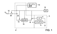
図1は、本願発明の一態様による、電動車両(特に、線路を走る車両、又は架空線を備える路面電車)のための電力供給システム1を図式的に示す。電力供給システム1は、スーパーキャパシタの配列2とバッテリのスタック4(例:リチウムイオンバッテリ)とを含む補助電力供給アセンブリ3と、スーパーキャパシタの配列2とバッテリのスタック4とにより共同使用されるエネルギー交換回路6とを含む。スーパーキャパシタの配列2とバッテリのスタック4は、直流タイプのそれぞれの電気量(電圧/電流)を供給するよう構成され、それぞれの電圧値を有する(例:バッテリのスタックが約500Vの電圧を提供するのに対し、スーパーキャパシタの配列2は、その充電のレベルに応じて55〜250Vの範囲の電圧を供給する)。
FIG. 1 schematically shows a
エネルギー交換回路6は以下を含む:
− 主電力供給スイッチ22。エネルギー交換回路6を主電力供給線12(電力供給電圧VAL、特に、例えば750Vの値を有する直流電圧を供給する)へ/から電気的に連結/分離するよう構成される。
− 伝送スイッチ14。(主電力供給スイッチ22と共に)スーパーキャパシタの配列2及びバッテリのスタック4を主電力供給線12へ/から電気的に連結/分離し、電気負荷10をスーパーキャパシタの配列2及びバッテリのスタック4へ/から電気的に連結/分離するよう構成される。
The energy exchange circuit 6 includes:
The main
-
主電力供給スイッチ22は、電力供給システム1のそれぞれの動作手順の間、主電力供給線12を電力供給システム1へ/から電気的に連結/分離する機能を実行する。例えば、主電力供給線12が電気負荷10から及び補助電力供給アセンブリ3から電気的に分離されなければならない状況は、供給のない線の区域(中立区域)の通過を含む。
The main
明らかに、代替的な実施形態によると、主電力供給スイッチ22、及び/又は伝送スイッチ12は省略され得る。エネルギー交換回路6は、さらに、伝送スイッチ14をバッテリ4のスタックに、又はスーパーキャパシタの配列2に、代替的に動作可能に連結するよう構成されるスイッチ16を含む。スイッチ16は、電気機械的デバイスによって、又は半導体と共に製造され得る。
Obviously, according to alternative embodiments, the main
特に、双方向DC−DCコンバータ18は、伝送スイッチ14と選択スイッチ16との間に電気的に介在する。
In particular, the bidirectional DC-
主電力供給線12が、バッテリのスタック4、及び/又はスーパーキャパシタの配列2が動作する電圧より高い電圧で動作する特定の場合、DC−DCコンバータ18は、電気エネルギーを主電力供給線12からバッテリのスタック4へ又はスーパーキャパシタの配列2へ供給するためのバックコンバータとして、また、電気エネルギーをバッテリのスタック4から又はスーパーキャパシタの配列2から電気負荷10へ供給するためのブーストコンバータとして動作するよう構成される。
In the particular case where the main
明らかに、主電力供給線12が、バッテリ4のスタック及び/又はスーパーキャパシタの配列2が動作する電圧より低い電圧で動作する場合、DC−DCコンバータ18は、上述されたものと反対に動作する。
Obviously, if the main
さらに、我々が詳細を以下で説明するように、バッテリのスタック4から、又は、代わりにスーパーキャパシタの配列2から電気負荷10へエネルギーを伝送するために、DC−DCコンバータ18は、バッテリのスタック4によって、又は、代わりにスーパーキャパシタの配列2によって電気負荷10に電力が供給されるステップの間も動作する。
Further, to transfer energy from the battery stack 4, or alternatively from the
一般的に、DC−DCコンバータ18は、主電力供給線12からバッテリのスタック4及び/又はスーパーキャパシタの配列2へエネルギーを伝送し、バッテリのスタック4から又はスーパーキャパシタの配列2から電気負荷10へエネルギーを伝送するためのエネルギー適合を実行する。
In general, the DC-
伝送スイッチ14は、電力供給スイッチ22が閉のときに主電力供給線12から電力の供給を受ける中間ノード25と電気的に連結する端子を有する。
The
この点に関して、電気負荷10は、車両の少なくとも1つのインバータと1つの電気モータを含み、車両自身のためのトルクを生成するために適合する。主電力供給線12は、電力を一般的な電動車両に供給することに適する全ての配線であり、電気車両の外部に配置され、特に架空線を備える電車又は路面電車のための電力の供給のための基盤の一部である。
In this regard, the
バッテリのスタック4の蓄電池の数、及びスーパーキャパシタの配列2を構成するスーパーキャパシタの数は、以下の基準によって選択される:各充電/放電サイクルの間に貯蔵及び解放されるエネルギーの量、吸収/供給される最大電力、スーパーキャパシタ及びバッテリの耐用期間に関して得られる性能。
The number of accumulators in the stack of batteries 4 and the number of supercapacitors that make up the
スーパーキャパシタは、エネルギーを変換及び貯蔵するためのデバイスであり、高い比容量によって特徴づけられ、体積単位あたりで従来のキャパシタと比較して際立って大きなエネルギーの量を貯蔵することができる。スーパーキャパシタは、科学文献によく記録されており、市場では異なるサイズの容量−数ファラドから数千ファラドまで−が入手でき、製造技術に依存するどのような場合でも、数ボルトの動作電圧の、互いに直列に配置される単位セルの「ストリング」を並列に接続して通常製造される。いくつかの製造業者は、1つのキャパシタのパッケージで、又は、直列及び/又は並列に接続された異なるスーパーキャパシタからなるモジュールでキャパシタを供給する。 Supercapacitors are devices for converting and storing energy, which are characterized by a high specific capacity and can store a significantly larger amount of energy per volume unit compared to conventional capacitors. Supercapacitors are well documented in the scientific literature and are available in capacities of different sizes on the market-from a few farads to thousands of farads-and at any operating voltage of a few volts, depending on the manufacturing technology. It is usually manufactured by connecting "strings" of unit cells arranged in series with each other in parallel. Some manufacturers supply capacitors in one capacitor package or in modules consisting of different supercapacitors connected in series and/or in parallel.
本願発明の一態様によると、スーパーキャパシタの配列2は第1の付加電力供給ユニットを形成し、電動車両の所定の動作ステップの間、特に電動車両の加速ステップの間に、第1の付加電力供給ユニットは、電気負荷10(電気モータ)への電力の供給において主電力供給線12をサポートする機能を実行する。
According to one aspect of the present invention, the array of
本願発明の追加的な一態様によると、バッテリのスタック4は第2の付加電力供給ユニットを形成し、電動車両の所定の動作ステップの間、特に主電力供給線12が、電気負荷10に電力を供給するための電流を提供しないとき(例えば、電力供給の中断の原因となった主電力供給線12の一般的な故障に起因する)、又は、環境的な又は都市計画的な理由に起因して主電力供給線12が利用できない区域で、第2の付加電力供給ユニットは、電気負荷10(電気モータ)への電力の供給において主電力供給線12を置き換える機能を実行する。
According to an additional aspect of the present invention, the battery stack 4 forms a second additional power supply unit such that the main
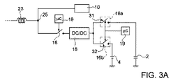
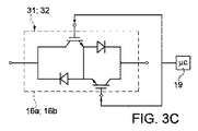
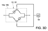
スイッチ16は図3Aに示されるように、例えば、第1及び第2の双方向電気スイッチ31、32によって作ることが可能であり、それらは両方とも開に保持されるか、相補ロジック(一方が閉、他方が開)により動作する。第1の双方向電気スイッチ31がインダクタ62とスーパーキャパシタの配列2との間を連結するのに対し、第2の双方向スイッチ32はインダクタ62とバッテリのスタック4との間を連結する。それらの動作の間、2つの双方向電気スイッチ31、32は、相補ロジックにより制御される:第1のスイッチ31が、DC−DCコンバータ18をスーパーキャパシタの配列2へ電気的に接続することにより(そして、従って、後者を中間ノード25へ接続することにより)オンになるよう制御されるとき、第2のスイッチ32は開に保たれ、逆もまた同様である。それ故に、第1及び第2のスイッチ31、32は、決して両方がON状態になるように制御されない。双方向電気スイッチ31、32は、TRIACによって(図3)、共通するそれぞれのエミッタにより互いに直列に連結する一組の逆導通MOSFET/IGBTによって(図3C)、又は、逆並列に連結する2つの逆阻止IGBTによって(図3D)、それぞれ実装され得る。
notが使用されるとき(例えば、電気モータ32がオフのとき)、第1及び第2の電気スイッチ31、32は、OFF状態になるように制御され得る。
When not is used (eg, when the
スイッチ14及びスイッチ16は、それらそれぞれの動作状態において、補助電力供給システム1の特定の要素に内蔵される又は補助電力供給システム1の外部にある汎用コントローラ又はマイクロコントローラ19によって、閉になるよう制御され得る。
The
もし、それが電力供給システム1の外側にあるなら、マイクロコントローラ19は、例えば、電動車両の制御/監視システム(図1に不図示)に内蔵されることができ、それは、スーパーキャパシタの配列2によって又はバッテリのスタック4によって車両の電気モータに供給される電力を必要とするイベントを検出するよう構成され得る。図5を参照してより詳細に説明されるステップによって、マイクロコントローラ19は、スーパーキャパシタの配列2又はバッテリのスタック4が充電され得るステップを検出するようさらに構成される。
If it is outside the
代わりに、マイクロコントローラ19への参照によって説明された機能は、インバータ30及びDC−DCコンバータ18に属する制御及び管理システムによって、分散方式で実行され得る。
Alternatively, the functions described by reference to the
マイクロコントローラ19(又は、代わりに、インバータ30の、及びDC−DCコンバータ18の制御及び管理システム)は、電流/電圧センサによって、線12の電力供給の状態の、及び、バッテリ4の及びスーパーキャパシタ2の充電の状態の情報を取得することによって、上述したタスクを実行し、それらは、電圧/電流のそれぞれのレベルを検出し、ひいてはバッテリ4及び/又はスーパーキャパシタ2を充電する必要/機会があるか、又は(主電力供給VALが存在しない場合に)バッテリ4によって電気モータ32に電力を供給する必要があるかを評価するために、線12の、DC−DCコンバータ18の出力に、及び、バッテリのスタック4の及びスーパーキャパシタ2の出力に、適切に配置される。
The microcontroller 19 (or, alternatively, the control and management system of the
そして、マイクロコントローラ19は、以下のために、それぞれの制御信号をスイッチ14に、及びスイッチ16に送信する:
電気負荷10に電力を供給するために、スーパーキャパシタの配列2を電気負荷10に接続するため。
又は、電気負荷10に電力を供給するために、バッテリのスタック4を電気負荷10に接続するため。
又は、バッテリのスタック4を充電するために、バッテリのスタック4をネットワーク電力供給12のソースに接続するため。
又は、特に電動車両の制動ステップの間、DC−DCコンバータ18によって電流発生器として使用される電気モータ32を介してスーパーキャパシタの配列2を充電するために、スーパーキャパシタの配列2を電気負荷10に接続するため。実際、制動ステップにおける電動車両の運動エネルギーは、既知の方法で電気エネルギーに変わり得るものであり、電気エネルギーは、スーパーキャパシタに貯蔵され、電動車両の以下の動作ステップで再使用され得る。
The
To connect the
Alternatively, to connect the stack 4 of batteries to the
Or to connect the stack 4 of batteries to the source of the
Alternatively, the
スイッチ14及びスイッチ16は電気機械デバイスであってもよく、また、それらは電子デバイス(例:ダイオード、トランジスタ、MOSFET、TRIAC、IGBT等)の組み合わせによって製造され得る。
図1の電力供給システム1は、さらに、既に上述した通り、双方向DC−DCコンバータであり、且つ、その入力電圧をブースト又はバックすることにより動作するDC−DCコンバータ18を含む。例えば、それはバック/ブーストコンバータであってもよく、必要に基づいてバックステップ又はブーストステップを実行するため、その動作の中で、既知の方法でマイクロコントローラ19によって制御される。
The
負荷10の、及び、利用可能な異なる電力供給源(すなわち、線12、バッテリ4及びスーパーキャパシタ2)の電圧レベルは、互いに異なり、また、スーパーキャパシタの場合は充電/放電ステップの間に極めて変化しやすいため、DC−DCコンバータ18は有効になる。
The voltage levels of the
要約すると、DC−DCキャパシタ18は、バッテリのスタック4及びスーパーキャパシタの配列2が電気負荷10から要求される電力を供給することを許可し、生成される電圧及び電流値に関して電気負荷10のために最適な条件で同時に動作する機能を実行する。さらに、主電力供給線12に存在する電圧に関わらず出力を一定値に保つために、DC−DCコンバータ18は、バッテリのスタック4の、及びスーパーキャパシタの配列2の充電電圧を調整することによって動作する。DC−DCコンバータ18は、バッテリのスタック4によって、また、スーパーキャパシタの配列2によって供給される電流及び/又は電圧を測定する機能を、さらに実行できる。バッテリのスタック4の、及びスーパーキャパシタの配列2の動作条件をチェックするために、測定結果はマイクロコントローラ19に送信され処理され得る。
In summary, the DC-
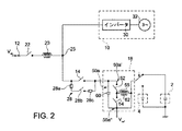
図2は、本願発明の一態様による電力供給システム1をより詳細に示す。図1を参照して既に上述された電力供給システムの要素は、同一の参照番号で示され、これ以上説明されない。
FIG. 2 shows the
図2を参照すると、電力供給システム1は、電力供給線12によって吸収される高調波電流を減衰させるよう構成されるフィルタをさらに含む。このフィルタは、特に、LCフィルタである。本実施形態によると、このフィルタ、特にインダクタ23(LCフィルタの誘導成分“L”を構成する)、の一部は、主電力供給スイッチ22の端子と、電力供給システム1の中間ノード25との間に配置される。LCフィルタの容量成分“C”は、DC−DCコンバータ18に存在する容量成分(例えば、図2のキャパシタ60を参照)から、又は、電気モータを制御するトラクションコンバータに存在する容量成分(図2のトラクションコンバータ30を参照)から構成される。このようにして、LCフィルタは、電気負荷10を含むブランチと、補助電力供給アセンブリ3を含むブランチの両方に影響を与える。LCフィルタは任意であり、省略したり、上述されたものと異なるように製造されたりすることもできる。
Referring to FIG. 2, the
ここに考慮される実施形態において、電気負荷10は、主電力供給線12と電力が供給される電気モータ32との間のインタフェースの役割を果たす、少なくとも1つの既知のトラクションコンバータ30を含む。トラクションコンバータ30及びモータ32は、駆動チェーンを形成する。
In the embodiment considered here, the
プリチャージ回路28は、伝送スイッチ14と並列に電気的に連結し、保護素子28a(例:ヒューズ)と、保護素子28aと直接に接続される接触器28bと、接触器28bと直接に接続される抵抗28cとを含む。接触器28bが閉の時間における抵抗28cの下流のショートの場合、保護素子28aは抵抗28cを保護するよう適合するのに対し、抵抗28cは、DC−DCコンバータ18に供給される電圧/電流の起こり得る振動を弱めるよう適合する。このステップの間、DC−DCコンバータ18の容量成分は、保護素子28a及び抵抗28cを介して、電力供給電圧VALによって充電される。(ほんのわずかな秒数続き得る)プリチャージステップの終わりに、接触器28bはオフになり、伝送スイッチ14はオンになる。
The
「バックブーストコンバータ」と呼ばれる実施形態の1つとして、単なる例として、DC−DCコンバータ18は図2に図式的に示される。図2のDC−DCコンバータ18は、第1及び第2の端子50a´、50a´´(後者は基準電圧Vref、例えばグランド基準又は負の基準電圧、と接続する)を含む。第1の端子50a´は第1のスイッチ52と接続されるのに対し、第2の端子50a´´は第2のスイッチ54と接続される。従って、第1のスイッチ52及び第2のスイッチ54は、電気ノード55の領域で互いに接続される。
As one of the embodiments referred to as a "buck-boost converter," by way of example only, a DC-
さらに、第1及び第2の端子50b´、50b´´の間で、第1及び第2のスイッチ52、54によって形成される直列接続と並列に、蓄電池素子60(一般的には、キャパシタ又はキャパシタの配列)が介在する。
Further, between the first and second terminals 50b′, 50b″, in parallel with the series connection formed by the first and
最後に、電気ノード55はインダクタ62と接続される。
Finally,
第1及び第2のスイッチ52、54は、例えば逆導通IGBT素子、言い換えれば、逆並列に集められたそれぞれのダイオードにより提供されるIGBTである。
The first and
使用するとき、双方向DC−DCコンバータは、補助電力供給アセンブリ3が電力を電気負荷10に供給するステップの間と、スーパーキャパシタの配列2、又は、代わりに、バッテリのスタックが充電されるステップの間との両方で使用される。明らかに、電力供給システム1は、図2で示されたタイプとは異なる、双方向DC−DCコンバータのその他の既知のタイプを含むことができる。
In use, the bi-directional DC-DC converter includes a step in which the auxiliary power supply assembly 3 supplies power to the
さらに、2つの単方向DC−DCコンバータが使用され得る。例えば、ブーストコンバータとバックコンバータ、又は、伝送スイッチ14と補助電力供給ユニット3との間で接続される2つのバックブーストコンバータ。
Moreover, two unidirectional DC-DC converters can be used. For example, a boost converter and a buck converter, or two buck boost converters connected between the
図4を参照して、図1及び2の電力供給システム1が動作する方法の例について説明する。
An example of how the
図4において、x座標の“t”軸は時間軸であり、電力供給システム1によって実行される機能を識別する信号の時間の進行を示す。この目的のために、y座標の軸は、kWで示される、電力供給システム1を構成する異なる要素の間で交換される電力を示す。この図はまた、電動車両の異なる動作ステップと関連づけて電力曲線の進行を示すために、電動車両の速度(km/h)の進行を示す曲線をこれらの電力曲線に重ねて示す。
In FIG. 4, the “t” axis of the x coordinate is the time axis, and shows the time progression of the signal for identifying the function performed by the
曲線S1は、表示の均等性を確保するために電動車両の速度を10km/hで示す。時刻t0において、電動車両は駐車場にあると仮定され、その速度は0に等しい。時刻t0と時刻t1との間に電動車両は加速し、時刻t1で70km/hの最高速度に達する。 Curve S1 shows the speed of the electric vehicle at 10 km/h in order to ensure display uniformity. At time t 0 , the electric vehicle is assumed to be in the parking lot and its speed is equal to 0. The electric vehicle accelerates between time t 0 and time t 1 and reaches the maximum speed of 70 km/h at time t 1 .
曲線S2は、時刻t0と時刻t1との間、すなわち電動車両の加速ステップの間に主電力供給線により供給される電力を示す。曲線S3は、電動車両のモータ32によって吸収される電力を示す。
Curve S2 shows the power supplied by the main power supply line between time t 0 and time t 1 , ie during the acceleration step of the electric vehicle. Curve S3 shows the electric power absorbed by the
ご覧の通り、主電力供給線12により供給される電力(曲線S2)は、最大値まで増加し、そして落ち着き、モータ32によって必要とされ吸収される電力の機能に応じてその値は次第に減少する。特に、モータ32は、時刻t1に近い時刻に達するとき、電力の要求を次第に減少させる。
As can be seen, the power supplied by the mains supply line 12 (curve S2) increases to a maximum value and then settles down, the value gradually decreasing depending on the function of the power required and absorbed by the
図4で分かるように、曲線S2は曲線S3の近くを進む。しかしながら、曲線S3は、モータによって吸収されるkWの値を、主電力供給線12により提供されるそれぞれのkWの値より常に大きく保つ。実際、本願発明によると、エネルギーの要求とその消費とが最大のステップの間に電動車両のモータ32へ付加的な電力(曲線S4)を供給するために、スーパーキャパシタの配列2に貯蔵されたエネルギーは、時刻t0と時刻t1との間にモータ32へ伝達される。従って、結果として、モータ32により吸収される電力は、主電力供給線12から引き込まれ得る電力よりも大きく、特に、スーパーキャパシタの配列2により提供される量と等しい量だけ大きい。
As can be seen in FIG. 4, curve S2 runs near curve S3. However, the curve S3 keeps the value of kW absorbed by the motor always greater than the value of the respective kW provided by the
図2及び3を参照すると、時刻t0と時刻t1との間で動作ステップが行われる間、電力供給スイッチ22は閉である。このステップの間、スーパーキャパシタの配列2をDC−DCコンバータ18へ電気的に連結するように、且つ、バッテリのスタック4をDC−DCコンバータ18から電気的に分離するように、選択スイッチ16は制御される。キャパシタの配列の電圧レベルをブーストし、結果としてスーパーキャパシタの配列2に貯蔵されたエネルギーを電気負荷10へ伝送するため、伝送スイッチ14はON状態に制御され、DC−DCコンバータ18は一般的に「ブースト」モードで動作する。
Referring to FIGS. 2 and 3, the
時刻t1に、電動車両は加速ステップを終了する。従って、その間に徐々に弱くなり、最低電圧値に達したスーパーキャパシタの配列2によって、モータへさらに電力を供給することは不要である。加速ステップが終了した後に、実質的に一定速度(「惰性走行(coasting)」と呼ばれる)の走行ステップ(時刻t1と時刻t2との間の時間間隔)が開始し、その間、主電力供給線12はモータへ電力を供給しない。このステップの間、電動車両は慣性によって走行する。主電力供給線12はモータへ電力を供給するために使用されないので、主電力供給線12により供給される電力は、この時間間隔t1−t2の間、バッテリのスタック4を充電するために使用され得る。この目的のため、時刻t1において、選択スイッチ16は、スーパーキャパシタの配列2をDC−DCコンバータ18から分離し、バッテリのスタック4をDC−DCコンバータ18へ連結する。スイッチ22はオンにされ、伝送スイッチ14も同様にオンにされる。充電電流は、主電力供給線12からDC−DCコンバータ18を経由して、バッテリのスタック4へ流れる。DC−DCコンバータ18は一般的に「バック」設定で動作する。
At time t1, the electric vehicle ends the acceleration step. Therefore, it is not necessary to supply further power to the motor by the
時刻t2において、電動車両は制動ステップを開始する。このステップの間、モータ32はエネルギー発生器として働く。時刻t2において、選択スイッチ16は、スーパーキャパシタの配列2をDC−DCコンバータ18へ電気的に連結するよう、且つ、バッテリのスタック4をDC−DCコンバータ18から電気的に分離するよう切り替わる。
In time t 2, the electric vehicle starts braking step. During this step, the
主電力供給スイッチ22及び伝送スイッチ14はオンになる。DC−DCコンバータ18は「バック」モードで動作し、電流発生器として動作するモータ32によって提供されるエネルギーを受け取り、このようにしてそれをスーパーキャパシタの配列2へ向けて伝送し、そうすることによってスーパーキャパシタの配列2は充電される。
The main
実際、曲線S4は、t2とt3との間で負の値をとる(すなわち、スーパーキャパシタ2は電力を受け取り、エネルギーを貯蔵する)。同じ時間間隔で、曲線S3は負である。すなわち、モータは電力を吸収する代わりに発生する。モータによって提供されるエネルギーのすべてがスーパーキャパシタの配列2によって貯蔵されるとは限らない。モータから供給されるエネルギーがスーパーキャパシタの配列2の容量を超える場合、貯蔵されないエネルギーはそこから主電力供給線12へ導入され得る。後者が受け入れ可能な場合、エネルギーは、適切なチョッパーによって挿入される適切な制動抵抗器によって熱に変わる。これは図4において曲線S2によって示され、t2とt3との間で負の値を有する(すなわち、主電力供給線12が電力を吸収する)。
In fact, the curve S4 has a negative value between t 2 and t 3 (ie the
時刻t3において、電動車両は制動ステップを終了し、停止する(例:電車の駅において)。このステップの間に、バッテリのスタック4の充電を完了し得る。この目的のために、駐車ステップが検出されたとき、選択スイッチ16は、バッテリのスタック4をDC−DCコンバータ18へ電気的に連結し、伝送スイッチ14を開に保つことによって、電気エネルギーを主電力供給線12からバッテリのスタック4へ提供する(DC−DCコンバータ18は一般的に「バック」モードで動作する)。
At time t3, the electric vehicle ends the braking step and stops (eg, at a train station). During this step, charging of the battery stack 4 may be completed. To this end, when a parking step is detected, the
本願発明の一態様によると、1つのステップから次のステップへの移行は、図4を参照して説明されたことに従って、電動車両全体の制御/監視システム(例:鉄道車両の場合、TCM −“Train Control and Monitoring System”)、すなわち、1つのトラクション及びエネルギー貯蔵チェーンを制御するトラクション制御部(TCU − “Traction Control Unit”)によって制御される。このタイプの車内制御システムは、少なくとも1つのコントローラ又はマイクロコントローラ(例:マイクロコントローラ19)が提供される処理システムを一般的に含む。図4の動作ステップは、例えば、マイクロコントローラ19で実行される、図5に示されるようなステートマシンのステップとして説明される。 In accordance with one aspect of the present invention, the transition from one step to the next is in accordance with what has been described with reference to FIG. 4, a control/monitoring system for the entire electric vehicle (eg TCM- "Train Control and Monitoring System"), that is, a traction control unit (TCU-"Traction Control Unit") that controls one traction and energy storage chain. This type of in-vehicle control system typically includes a processing system in which at least one controller or microcontroller (eg, microcontroller 19) is provided. The operational steps of FIG. 4 are described, for example, as steps of a state machine as shown in FIG.
図5を参照すると、ノードN1は、電動車両の加速ステップの間に補助電力供給をモータ32に提供するためにスーパーキャパシタの配列2が放電される状況を表す。電動車両が加速状態にとどまる限り(そして、明らかに、スーパーキャパシタの配列がエネルギーを供給するために十分に充電されている限り)、車内制御システムはノードN1の条件にとどまる。
Referring to FIG. 5, node N1 represents the situation where
ノードN2は、バッテリのスタック4の充電状態を表す。この状態は、すでに上述した通り、電動車両が駐車しているとき、又は、一定速度の走行ステップにあるとき(電力供給電圧VALによって供給されない、又は、最小限供給される)に発生する。電動車両がこの状態にとどまる限り、バッテリのスタック4は、主電力供給線12から取得されるエネルギーによって充電される。電動車両が加速するよう制御される場合、ノードN1のステップに戻る。
Node N2 represents the state of charge of the stack 4 of batteries. As already mentioned above, this state occurs when the electric vehicle is parked or in a constant speed traveling step (not supplied by the power supply voltage V AL or supplied at a minimum). As long as the electric vehicle remains in this state, the battery stack 4 will be charged by the energy taken from the
ノードN3は、スーパーキャパシタの配列2が充電される状態を表す。ノードN1又はノードN2からノードN3への進展は、制動の存在下で、すなわち、モータ32が電気エネルギー発生器として動作するときに発生する。電動車両の制御システムが制動を介してエネルギー発生の状態にとどまる限り、ノードN3の状態にとどまる。加速の存在下で、ノードN3ノードN1への移行が存在し、そうでなければ、電動車両の駐車の、又は、供給のない走行の存在下で、ノードN2への移行が存在する。
Node N3 represents the state in which
バッテリのスタック4は、例えば主電力供給線12の一般的な障害のような特定の場合に、又は、バッテリのスタック4が電動車両の電力の唯一のソースである条件下で、電力を電動車両へ供給するために使用される。これらの場合において、バッテリのスタックによって提供されるエネルギーは、電動車両を安全な場所へ移動するために、例えば、トンネルから脱出するため又は電車の駅か街の近くに到着するために使用される。この目的のために、システムが主電力供給電圧VALの欠如を検出し、且つ、電動車両の走行を許可するために電気モータ32に電力を供給することが必要な場合、ノードN1、N2及びN3から、バッテリのスタック4が電気モータ32へ電力を供給することにより放電されるノードN4への移行が存在する。制動ステップの間、電力供給電圧VALが存在するか否かに関わらずノードN3に戻り、そうでなければ、ノードN3の状態にとどまる。電力供給電圧VALが復帰するとき、必要に応じて、ノードN4からノードN1、N2及びN3への移行が存在し得る。
The battery stack 4 may provide power to the electric vehicle in certain cases, such as a general failure of the main
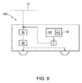
図6は、加速、一定速度での走行、及び制動を制御するために、特にトラクションコンバータ30を介して主電力供給線12と電気的に連結し、且つ、電動車両100のトラクションシステムと動作可能なように連結する電気モータ32と、図5のステップを実行するよう構成される、マイクロコントローラ19を含む制御システム102と、上述したそれぞれの実施例に従う、図1又は図2の電力供給システム1と、を含む電動車両100を図式的に示す。
FIG. 6 shows an electrical connection, in particular via the
電動車両は以下からなるグループから選択される:電車、トロリーバス、又は、一般的な外部電力供給ネットワークによって電力を供給される他の電動車両。 The electric vehicle is selected from the group consisting of: a train, trolleybus, or other electric vehicle powered by a common external power supply network.
上述され、添付された図面に示された特徴の分析より、本願発明が達成しようとする長所を明らかに理解することができる。特に、本願発明の結果、
(i)制動ステップの間に車両の運動エネルギーを車内で収穫し、スーパーキャパシタに貯蔵される電気エネルギーに変換し、以下の加速ステップにおいて再使用することによって、車両のエネルギー効率を向上させ得る。これは、コスト及び環境の持続可能性の観点における鉄道会社にとっての優れた強みであるとともに、メーカーがエネルギー消費を削減することを許す。
(ii)主電力供給線の電力のピーク及び実効電流を制限し得る。すなわち、主電力供給線の同一のピーク電力を仮定すると、鉄道車両のピーク性能を増加させ得る。これは、基幹施設に投資することなく、特に電力供給変電所をさらに開発したり増加させたりする必要なしに、メーカーが保有鉄道車両の性能を向上させる(言い換えれば、線上の車両の数を増加させる、すなわち、加速の観点からはその性能を向上させる)ことを許す。
(iii)電動車両は、主電力供給なしで著しい長さの経路をカバーすることが可能である。これは、車両の用途をより広くし、主電力供給線の存在と両立しない歴史的及び建築学的価値を有する場所、主電力供給線の存在しない倉庫又は修理店、基幹施設で実施される保守作業により電力が供給されない主電力供給線の区域、例えば主電力供給線の電力供給故障の場合、乗客を安全に外に出すために車両をトンネルの外へ出し駅に到着することを許す緊急走行、及び、主電力供給線の凍結した小区域を含む経路で使用されることを許す。
From the analysis of the features described above and shown in the accompanying drawings, the advantages to be achieved by the present invention can be clearly understood. In particular, as a result of the present invention,
(I) The energy efficiency of the vehicle may be improved by harvesting the kinetic energy of the vehicle in the vehicle during the braking step, converting it into electrical energy stored in a supercapacitor and reusing it in the following acceleration step. This is a great strength for railway companies in terms of cost and environmental sustainability, as well as allowing manufacturers to reduce energy consumption.
(Ii) It may limit the peak power and the effective current of the main power supply line. That is, assuming the same peak power of the main power supply line, the peak performance of the railway vehicle can be increased. This improves the performance of railway vehicles owned by manufacturers without the need to invest in infrastructure, especially without the need to further develop or increase power supply substations (in other words, increase the number of vehicles on the line). That is, from the viewpoint of acceleration, improve its performance).
(Iii) Electric vehicles can cover paths of significant length without a mains supply. This makes the vehicle more versatile and has historical and architectural value that is incompatible with the existence of main power supply lines, warehouses or repair shops where there is no main power supply line, maintenance carried out in infrastructure. In the case of an area of the main power supply line where power is not supplied due to work, for example, in the case of a power supply failure of the main power supply line, an emergency run that allows the vehicle to move out of the tunnel and reach the station in order to safely leave passengers , And allow it to be used on routes that include frozen subregions of the mains supply lines.
スーパーキャパシタの配列は、電動車両の1回の制動で収穫されるエネルギーを貯蔵することができるようなサイズにすることができる。このエネルギーは、電動車両が駐車している限りスーパーキャパシタに保持され、加速ステップの間に速やかに供給され、結果としてスーパーキャパシタを初期の「放電」状態に戻し、以下の制動ステップのエネルギーを貯蔵する準備がなされる。このエネルギー交換は、極めて短い時間(約10秒)の間の関連のあるピーク電力(電動車両次第で、約数百kW)によって特徴づけられ、従って、適度なエネルギーを有する。結果として、スーパーキャパシタは、適度な重みの部品の関連するピーク電力を吸収する/供給する能力のおかげで、非常に便利であると分かる部品である。 The array of supercapacitors can be sized to store the energy harvested with a single braking of the electric vehicle. This energy is retained in the supercapacitor as long as the electric vehicle is parked, and is quickly delivered during the acceleration step, resulting in the supercapacitor returning to its initial “discharge” state, storing energy for the following braking steps. Ready to do. This energy exchange is characterized by a relevant peak power (about several hundred kW, depending on the electric vehicle) for a very short time (about 10 seconds) and thus has a modest energy. As a result, supercapacitors are components that prove to be very convenient, due to their ability to absorb/deliver the associated peak power of moderately weighted components.
他方で、バッテリのスタックは、主電力供給線の電力供給がない場合に車両を動かすために必要とされる大量のエネルギーを貯蔵するためのサイズである。この走行モードは低速で起こるので、必要とされる充電電力は制限される。他方で、バッテリは相対的に短時間で、電動車両のすべての「惰性走行」(一定速度で走行すること)及び駐車ステップ(例えば、2つのバッテリ走行ステップの間で生じる)を利用して充電され得る。通常の加速及び制動のサイクルの間、バッテリは環境発電を実行するために使用されないため、バッテリによって供給され得る制限された比電力(specific power)は重要なサイズの制限を構成せず、それらの比エネルギー(specific energy)は全部利用され得る。同様に、バッテリが経験する充電及び放電サイクルの数は、スーパーキャパシタが受けるそれよりも非常に少なく、それらの耐用期間の間に許される制限された数に対応する。 On the other hand, the battery stack is sized to store the large amount of energy needed to power the vehicle in the absence of power on the mains supply line. Since this driving mode occurs at low speed, the charging power required is limited. On the other hand, the battery is charged in a relatively short time using all "coasting" of the electric vehicle (running at a constant speed) and parking steps (eg occurring between two battery driving steps). Can be done. During normal acceleration and braking cycles, the battery is not used to perform energy harvesting, so the limited specific power that can be supplied by the battery does not constitute a significant size limitation, and those Specific energy can be fully utilized. Similarly, the number of charge and discharge cycles that batteries experience is much less than that experienced by supercapacitors, corresponding to the limited number allowed during their lifetime.
鉄道車両に一般的に存在する低電圧の車内サービスのバッテリとは違って、本願発明の実施態様に従って使用されるリチウムバッテリは、トラクション回路へ(言い換えれば、電気モータ32へ)接続され、そして、従って、それらはガルバニック絶縁を確保するために動作する充電器を必要としない。従って、リチウムバッテリの充電/放電曲線を温度にも応じて実行することは可能なので、スーパーキャパシタ(言い換えれば、DC−DCコンバータ18及びスイッチ16)とのエネルギー交換のために使用される電力回路はまた、バッテリからの電力を充電/入手するためにも使用される。特に、多くのスペースを占めるコンバータの部品であるインダクタ62は、重く高価であり、ユニークであり、スーパーキャパシタの充電/放電モードとバッテリの充電/放電モードとの両方で動作する。
Unlike low voltage in-vehicle service batteries commonly present in rail vehicles, lithium batteries used in accordance with embodiments of the present invention are connected to a traction circuit (in other words, to electric motor 32), and Therefore, they do not require a working charger to ensure galvanic isolation. Therefore, since it is possible to carry out the charge/discharge curve of a lithium battery as a function of temperature, the power circuit used for energy exchange with the supercapacitor (in other words, the DC-
最後に、添付の図面を参照して上述された特徴は、添付された特許請求の範囲に記述される本願発明の保護の範囲をこの理由により超えることなく、変更及び変形され得る。 Finally, the features described above with reference to the accompanying drawings may be modified and varied for this reason without exceeding the scope of protection of the invention as described in the appended claims.
例えば、バッテリのスタックによって及び/又はスーパーキャパシタ2によって生成される電圧レベルが、電気負荷10が電力を直接供給されるような場合、DC−DCコンバータ18は一方向のコンバータであり、バッテリのスタック/スーパーキャパシタ2を充電するために(逆もまた同様に)、ネットワーク電圧VALの及び負荷10により生成される電圧の変換を行うように適合する。さらに、ネットワーク電圧VAL及び負荷10により生成される電圧が、バッテリのスタック/スーパーキャパシタ2を充電するためにDC−DC変換を必要としない場合、DC−DCコンバータは省略され得る。
For example, if the voltage level produced by the stack of batteries and/or by the
特に、バッテリのスタック4は、例えばリチウム、鉛、NiCd、NiMH、ZEBRA又は他の、全ての利用可能な技術のバッテリを含み得る。同様に、スーパーキャパシタの配列はウルトラキャパシタによって置き換えられ得る。 In particular, the battery stack 4 may include batteries of all available technologies, for example lithium, lead, NiCd, NiMH, ZEBRA or other. Similarly, the array of supercapacitors can be replaced by ultracapacitors.
一般的に、補助電力供給アセンブリ3は、第1の蓄電池モジュール(上述されたスーパーキャパシタの配列2に対応)、及び、第2の蓄電池モジュール(上述されたバッテリのスタック4に対応)を含む。2つの蓄電池モジュールのそれぞれの電圧値は、ある制限内で、線間電圧と調和するよう適切に決定され得るが、バッテリモジュールは充電及び放電ステップの間にあまり変わらない電圧を有するのに対して、スーパーキャパシタは充電及び放電ステップの間に大きな電圧変動、例えば50%の変動、を受ける。さらに、図7は、現在市場で入手可能ないくつかのスーパーキャパシタ及びバッテリの性能の電力密度−エネルギー密度図を示す。例えば、電力は重量単位で供給/吸収されるものとして考慮され、エネルギーは重量単位で貯蔵/解放されるものとして考慮される。
In general, the auxiliary power supply assembly 3 comprises a first accumulator module (corresponding to the
本願発明によると、重量と、占めるスペースと、電力供給及び環境発電システムのコストとを最小化するために、第1の蓄電池モジュールは、その低いエネルギー密度を受け入れるために、高電力密度を供給しなければならず、且つ、その耐用期間に多くのサイクルを可能にしなければならない。反対に、第2の蓄電池モジュールは、その低い電力密度(すなわち、第1の蓄電池モジュールにより提供される電力密度より低い)と、その耐用期間に少数の充電/放電サイクルを担う能力(すなわち、第1の蓄電池モジュールが担い得る充電/放電サイクルの数より少ない)とを受け入れるために、高いエネルギー密度(第1の蓄電池モジュールにより提供されるエネルギー密度より高い)を供給しなければならない。 According to the present invention, in order to minimize the weight, the space occupied, and the cost of the power supply and the energy harvesting system, the first storage battery module supplies a high power density to accept its low energy density. It must be, and must allow for many cycles in its useful life. On the contrary, the second accumulator module has a low power density (ie lower than the power density provided by the first accumulator module) and the ability to carry a small number of charge/discharge cycles during its useful life (ie the first accumulator module). A high energy density (higher than the energy density provided by the first accumulator module) must be provided in order to accept (less than the number of charge/discharge cycles that one accumulator module can carry).
Claims (12)
ネットワーク電力供給電圧(VAL)を供給するネットワーク電力供給線(12)及び前記駆動チェーン(10;30,32)と電気的に連結し得る電力供給端子(25)と、
第1の値を有する第1の補助電力供給電圧を生成するように構成される第1の蓄電池アセンブリ(2)及び第2の値を有する第2の補助電力供給電圧を生成するように構成される第2の蓄電池アセンブリ(4)を含む、前記電力供給端子(25)と電気的に連結し得る補助電力供給アセンブリ(3)と、
前記補助電力供給アセンブリ(3)と前記電力供給端子(25)との間に連結するスイッチ(16)と、
前記スイッチ(16)と動作可能に連結し、前記第1の蓄電池アセンブリ(2)又は前記第2の蓄電池アセンブリ(4)を、前記電力供給端子(25)と電気的に連結するように前記スイッチ(16)を制御するよう適合し、前記電動車両のそれぞれの動作条件を実行する制御ユニット(102,19)であって、
(i)前記第1の補助電力供給電圧と少なくとも一部が相互に関連する第1の中間電圧を前記駆動チェーンに供給する第1の動作状態と、
(ii)前記ネットワーク電力供給電圧(VAL)と相互に関連する第2の中間電圧によって、前記第2の蓄電池アセンブリ(4)を充電する第2の動作状態と、
(iii)前記第2の補助電力供給電圧と相互に関連する第3の中間電圧を前記駆動チェーン(10;30,32)に供給する第3の動作状態と、
(iv)電気発生器として動作する前記駆動チェーン(10;30,32)によって生成される回収電圧と相互に関連する第4の中間電圧によって、前記第1の蓄電池アセンブリ(2)を充電する第4の動作状態と、を含む制御ユニットと、
を含み、
前記第1の動作状態は、前記電動車両の加速であり、且つ、前記駆動チェーン(10;30,32)に、前記ネットワーク電力供給線(12)から電力の一部と、前記第1の蓄電池アセンブリ(2)から電力のさらなる一部とを供給して、前記第1の中間電圧を生成することを含み、
前記第2の動作状態は、前記電動車両の駐車又は実質的に一定速度での走行であり、且つ、前記第2の蓄電池アセンブリを充電することを目的とする電力に従って値が選択される前記第2の中間電圧によって、前記第2の蓄電池アセンブリ(4)を充電することを含み、
前記第3の動作状態は、主電力供給電圧(VAL)が欠如し、且つ、前記駆動チェーン(10;30,32)によって必要とされる動作電圧に従って値が選択される前記第3の中間電圧を前記駆動チェーン(10;30,32)に供給することを含み、
前記第4の動作状態は、前記電動車両の制動であり、且つ、前記回収電圧から得られ、前記第1の蓄電池アセンブリ(2)を充電することを目的とする前記電力に従って値が選択される、前記第4の中間電圧によって、前記第1の蓄電池アセンブリ(2)を充電することを含む、補助エネルギー管理システム。 An auxiliary energy management system (1) for at least one drive chain (10; 30, 32) of an electric vehicle (100),
A network power supply line (12) for supplying a network power supply voltage (V AL ) and a power supply terminal (25) electrically connectable with the drive chain (10; 30, 32);
A first accumulator assembly (2) configured to generate a first auxiliary power supply voltage having a first value and a second storage battery assembly configured to generate a second auxiliary power supply voltage having a second value. An auxiliary power supply assembly (3) that can be electrically coupled to the power supply terminal (25), including a second storage battery assembly (4),
A switch (16) connected between the auxiliary power supply assembly (3) and the power supply terminal (25);
The switch is operably connected to the switch (16) to electrically connect the first storage battery assembly (2) or the second storage battery assembly (4) to the power supply terminal (25). A control unit (102, 19) adapted to control (16) and executing respective operating conditions of said electrically powered vehicle,
(I) a first operating state for supplying to the drive chain a first intermediate voltage, at least a portion of which is interrelated with the first auxiliary power supply voltage;
(Ii) a second operating state of charging the second accumulator assembly (4) with a second intermediate voltage that correlates to the network power supply voltage (V AL );
(Iii) a third operating state in which a third intermediate voltage, which correlates to the second auxiliary power supply voltage, is applied to the drive chain (10; 30, 32);
(Iv) charging a first accumulator assembly (2) with a fourth intermediate voltage that correlates with a recovery voltage generated by the drive chain (10; 30, 32) operating as an electricity generator. And a control unit including four operating states,
Including
The first operating state is acceleration of the electric vehicle, and a part of the power from the network power supply line (12) to the drive chain (10; 30, 32) and the first storage battery. Supplying a further portion of electrical power from the assembly (2) to generate the first intermediate voltage,
The second operating state is parking or traveling at a substantially constant speed of the electric vehicle, and the value is selected according to power intended to charge the second storage battery assembly. Charging the second accumulator assembly (4) with an intermediate voltage of 2;
The third operating state is the third intermediate state in which the main power supply voltage (V AL ) is absent and the value is selected according to the operating voltage required by the drive chain (10; 30, 32). Supplying a voltage to the drive chain (10; 30, 32),
The fourth operating state is braking of the electric vehicle and is derived from the recovered voltage and a value is selected according to the power intended to charge the first storage battery assembly (2). An auxiliary energy management system comprising charging the first storage battery assembly (2) with the fourth intermediate voltage.
前記第1の動作状態の間に、前記スイッチ(16)は、前記第1の蓄電池アセンブリ(2)を前記双方向DC−DCコンバータ(18)と電気的に連結するように制御され、前記双方向DC−DCコンバータ(18)は、前記駆動チェーン(10;30,32)が受け入れる電圧レベルの関数として前記第1の補助電力供給電圧をブースト又はバックするように制御され、前記第1の中間電圧で前記駆動チェーンに供給する電力を、ネットワーク電力供給電圧(VAL)とともに供給し、
前記第2の動作状態の間に、前記スイッチ(16)は、前記第2の蓄電池アセンブリ(4)を前記双方向DC−DCコンバータ(18)と電気的に連結するように制御され、前記双方向DC−DCコンバータ(18)は、前記第2の蓄電池アセンブリ(4)が受け入れる電圧レベルの関数として前記ネットワーク電力供給電圧(VAL)をブースト又はバックするように制御され、前記駆動チェーン(10;30,32)に供給することに加えて又は前記駆動チェーン(10;30,32)に供給することの代わりに、前記ネットワーク電力供給線(12)は、前記第2の中間電圧(4)で前記第2の蓄電池アセンブリ(4)を充電する電力を供給し、
前記第3の動作状態の間に、前記スイッチ(16)は、前記第2の蓄電池アセンブリ(4)を前記双方向DC−DCコンバータ(18)と電気的に連結するように制御され、前記双方向DC−DCコンバータ(18)は、前記駆動チェーン(10;30,32)が受け入れる電圧レベルの関数として前記第2の補助電力供給電圧をブースト又はバックするように制御され、前記第3の中間電圧で前記駆動チェーンに供給する電力を供給し、
前記第4の動作状態の間に、前記スイッチ(16)は、前記第1の蓄電池アセンブリ(2)を前記双方向DC−DCコンバータ(18)と電気的に連結するように制御され、前記双方向DC−DCコンバータ(18)は、前記第1の蓄電池アセンブリ(2)が受け入れる電圧レベルの関数として前記回収電圧をブースト又はバックするように制御され、前記ネットワーク電力供給線(12)に加えて又は前記ネットワーク電力供給線(12)の代わりに、前記制動の間に発電機として動作する前記駆動チェーン(10;30,32)は、前記第1の蓄電池アセンブリ(2)を充電する電力を供給する、請求項1に記載の補助エネルギー管理システム。 A voltage level adaptation between the auxiliary power supply assembly (3) and the drive chain (10; 30, 32) operably arranged between the switch (16) and the power supply terminal (25). Adjusting the voltage level between the drive chain (10; 30, 32) and the auxiliary power supply assembly (3), and between the network power supply line (12) and the auxiliary power supply assembly (3) Further comprising one bidirectional DC-DC converter (18) configured to form an interface shared at alternating times for matching voltage levels of
During the first operating state, the switch (16) is controlled to electrically couple the first battery assembly (2) with the bidirectional DC-DC converter (18), and A direct DC-DC converter (18) is controlled to boost or buck the first auxiliary power supply voltage as a function of the voltage level received by the drive chain (10; 30, 32), the first intermediate The power supplied to the drive chain in voltage with the network power supply voltage (V AL ),
During the second operating state, the switch (16) is controlled to electrically couple the second storage battery assembly (4) with the bidirectional DC-DC converter (18), and both switches are connected to each other. A DC-DC converter (18) is controlled to boost or buck the network power supply voltage (V AL ) as a function of the voltage level received by the second storage battery assembly (4), and the drive chain (10). The network power supply line (12) in addition to or instead of supplying the drive chain (10; 30, 32), the second intermediate voltage (4). Power for charging the second battery assembly (4) at
During the third operating state, the switch (16) is controlled to electrically connect the second storage battery assembly (4) with the bidirectional DC-DC converter (18), and both switches are connected to each other. A direct DC-DC converter (18) is controlled to boost or buck the second auxiliary power supply voltage as a function of the voltage level received by the drive chain (10; 30, 32), and the third intermediate power supply voltage is controlled. Supply power to the drive chain with a voltage,
During the fourth operating state, the switch (16) is controlled to electrically couple the first storage battery assembly (2) with the bidirectional DC-DC converter (18), the both. A DC-DC converter (18) is controlled to boost or buck the recovery voltage as a function of the voltage level received by the first battery assembly (2), and in addition to the network power supply line (12). Or, instead of the network power supply line (12), the drive chain (10; 30, 32), which acts as a generator during the braking, supplies power to charge the first storage battery assembly (2). The supplemental energy management system according to claim 1.
前記第1の動作状態の間に、電圧ブーストモードで動作して、前記第1の蓄電池アセンブリ(2)から前記駆動チェーン(10;30,32)へエネルギーを伝送し、
前記第2の動作状態の間に、電圧バックモードで動作して、前記駆動チェーン(10;30,32)から前記第1の蓄電池アセンブリ(2)へエネルギーを伝送し、
前記第3の動作状態の間に、電圧バックモードで動作して、前記ネットワーク電力供給線(12)から前記第2の蓄電池アセンブリ(4)へエネルギーを伝送し、
前記第4の動作状態の間に、電圧ブーストモードで動作して、前記第2の蓄電池アセンブリ(4)から前記駆動チェーンへエネルギーを伝送するように、さらに構成される、請求項2に記載の補助エネルギー管理システム。 The bidirectional DC-DC converter (18) is
Operating in a voltage boost mode during the first operating state to transfer energy from the first battery assembly (2) to the drive chain (10; 30, 32);
Operating in a voltage back mode during the second operating state to transfer energy from the drive chain (10; 30, 32) to the first accumulator assembly (2);
Operating in a voltage back mode during the third operating state to transfer energy from the network power supply line (12) to the second storage battery assembly (4);
The method of claim 2, further configured to operate in a voltage boost mode to transfer energy from the second battery assembly (4) to the drive chain during the fourth operating state. Auxiliary energy management system.
前記第2の蓄電池アセンブリ(4)は、その耐用期間の間に、前記第1の蓄電池アセンブリ(2)がその耐用期間の間にサポートするように適合する充電又は放電サイクルの数より少ない充電又は放電サイクルの数をサポートするように適合する、請求項1〜4の何れか一項に記載の補助エネルギー管理システム。 The first storage battery assembly (2) is adapted to supply a first power density and a first energy density, and the second storage battery assembly (4) is lower than the first power density. Adapted to provide a second power density and a second energy density higher than said first energy density,
The second accumulator assembly (4) has less than the number of charge or discharge cycles during its useful life that the first accumulator assembly (2) is adapted to support during its useful life. An auxiliary energy management system according to any one of the preceding claims, adapted to support a number of discharge cycles.
トラクションコンバータ(30)を介して前記ネットワーク電力供給線(12)と電気的に連結する電気モータ(32)と、
前記電気モータ(32)と動作可能に連結し、加速、制動、駐車、及び実質的に一定速度の走行において前記電動車両(100)を制御する、前記電動車両(100)のトラクションシステムと、
前記電気モータ(32)と動作可能に連結する、請求項1〜7の何れか一項に記載の補助エネルギー管理システム(1)と、
前記補助エネルギー管理システム(1)と動作可能に連結し、前記第1の動作状態、前記第2の動作状態、前記第3の動作状態、及び前記第4の動作状態の間に前記補助エネルギー管理システム(1)の前記動作を制御する、制御ユニット(102,19)と、
を備える、電動車両(100)。 An electric vehicle (100),
An electric motor (32) electrically connected to the network power supply line (12) through a traction converter (30);
A traction system for the electric vehicle (100) operably coupled to the electric motor (32) for controlling the electric vehicle (100) during acceleration, braking, parking, and traveling at a substantially constant speed;
An auxiliary energy management system (1) according to any one of claims 1 to 7, operably connected to the electric motor (32),
Operatively coupled to the supplemental energy management system (1) for managing the supplemental energy during the first operating state, the second operating state, the third operating state, and the fourth operating state. A control unit (102, 19) for controlling said operation of the system (1),
An electric vehicle (100) comprising:
電力供給端子(25)でネットワーク電力供給電圧(VAL)を供給するステップと、
第1の蓄電池アセンブリ(2)によって、第1の値を有する第1の補助電力供給電圧を生成するステップと、
第2の蓄電池アセンブリ(4)によって、第2の値を有する第2の補助電力供給電圧を生成するステップと、
前記第1の蓄電池アセンブリ(2)又は前記第2の蓄電池アセンブリを、前記電力供給端子(25)と電気的に接続し、前記電動車両のそれぞれの動作状態を実行するステップであって、
(i)前記第1の補助電力供給電圧と少なくとも一部が相互に関連する第1の中間電圧を前記駆動チェーンに供給する第1の動作状態と、
(ii)前記ネットワーク電力供給電圧(VAL)と相互に関連する第2の中間電圧によって、前記第2の蓄電池アセンブリ(4)を充電する第2の動作状態と、
(iii)前記第2の補助電力供給電圧と相互に関連する第3の中間電圧を前記駆動チェーン(10;30,32)に供給する第3の動作状態と、
(iv)電気発生器として動作する前記駆動チェーン(10;30,32)によって生成される回収電圧と相互に関連する第4の中間電圧によって、前記第1の蓄電池アセンブリ(2)を充電する第4の動作状態と、を含む、ステップと、
を含み、
前記第1の動作状態は、前記電動車両の加速であり、且つ、前記駆動チェーン(10;30,32)に、ネットワーク電力供給線(12)から電力の一部と、前記第1の蓄電池アセンブリ(2)から電力のさらなる一部を引き込むことにより供給し、前記第1の中間電圧を生成するステップを含み、
前記第2の動作状態は、前記電動車両の駐車又は実質的に一定速度での走行であり、且つ、前記第2の蓄電池アセンブリを充電することを目的とする前記電力に従って値が選択される前記第2の中間電圧によって、前記第2の蓄電池アセンブリ(4)を充電するステップを含み、
前記第3の動作状態は、主電力供給電圧(VAL)が欠如し、且つ、前記駆動チェーン(10;30,32)によって必要とされる動作電圧に従って値が選択される前記第3の中間電圧を前記駆動チェーン(10;30,32)に供給するステップを含み、
前記第4の動作状態は、前記電動車両の制動であり、且つ、前記回収電圧から得られ、前記第1の蓄電池アセンブリを充電することを目的とする前記電力に従って選択される、前記第4の中間電圧によって、前記第1の蓄電池アセンブリ(2)を充電するステップを含む、方法。 A method of supplemental energy management of at least one drive chain (10; 30, 32) of an electric vehicle (100), comprising:
Supplying a network power supply voltage (V AL ) at a power supply terminal (25),
Generating a first auxiliary power supply voltage having a first value by the first battery assembly (2);
Generating a second auxiliary power supply voltage having a second value by the second battery assembly (4);
Electrically connecting the first storage battery assembly (2) or the second storage battery assembly to the power supply terminal (25) to execute respective operating states of the electric vehicle,
(I) a first operating state for supplying to the drive chain a first intermediate voltage, at least a portion of which is interrelated with the first auxiliary power supply voltage;
(Ii) a second operating state of charging the second accumulator assembly (4) with a second intermediate voltage that correlates to the network power supply voltage (V AL );
(Iii) a third operating state in which a third intermediate voltage, which correlates to the second auxiliary power supply voltage, is applied to the drive chain (10; 30, 32);
(Iv) charging a first accumulator assembly (2) with a fourth intermediate voltage that correlates with a recovery voltage generated by the drive chain (10; 30, 32) operating as an electricity generator. And 4 operating states, and
Including
The first operating state is acceleration of the electric vehicle and a portion of the power from the network power supply line (12) to the drive chain (10; 30, 32) and the first storage battery assembly. Supplying a further portion of power from (2) to produce the first intermediate voltage,
The second operating state is parking or traveling at a substantially constant speed of the electric vehicle, and the value is selected according to the power intended to charge the second storage battery assembly. Charging the second accumulator assembly (4) with a second intermediate voltage;
The third operating state is the third intermediate state in which the main power supply voltage (V AL ) is absent and the value is selected according to the operating voltage required by the drive chain (10; 30, 32). Providing a voltage to the drive chain (10; 30, 32),
The fourth operating state is braking of the electric vehicle and is derived from the recovered voltage and is selected according to the power intended to charge the first storage battery assembly. A method comprising charging said first accumulator assembly (2) with an intermediate voltage.
前記第2の動作状態の間に、前記第2の蓄電池アセンブリ(4)が受け入れる電圧レベルの関数として前記ネットワーク電力供給電圧(VAL)をブースト又はブックすることにより、前記第2の中間電圧を生成するステップと、
前記第3の動作状態の間に、前記駆動チェーン(10;30,32)が受け入れる電圧レベルの関数として前記第2の補助電力供給電圧をブースト又はブックすることにより、前記第3の中間電圧を生成するステップと、
前記第4の動作状態の間に、前記第1の蓄電池アセンブリ(2)が受け入れる電圧レベルの関数として前記回収電圧をブースト又はブックすることにより、前記第4の中間電圧を生成するステップと、をさらに含む、請求項9に記載の方法。 During the first operating state, the first intermediate voltage is boosted by boosting or booking the first auxiliary power supply voltage as a function of the voltage level received by the drive chain (10; 30, 32). The steps to generate,
During the second operating state, boosting or booking the network power supply voltage (V AL ) as a function of the voltage level received by the second battery assembly (4) reduces the second intermediate voltage. The steps to generate,
During the third operating state, boosting or booking the second auxiliary power supply voltage as a function of the voltage level received by the drive chain (10; 30, 32) reduces the third intermediate voltage. The steps to generate,
Generating the fourth intermediate voltage by boosting or booking the recovery voltage as a function of the voltage level received by the first battery assembly (2) during the fourth operating state. The method of claim 9, further comprising:
前記第2の動作状態の間に、電圧バックモードで動作して、前記駆動チェーンから前記第1の蓄電池アセンブリ(2)へエネルギーを伝送するステップと、
前記第3の動作状態の間に、電圧バックモードで動作して、前記ネットワーク電力供給線(12)から前記第2の蓄電池アセンブリ(4)へエネルギーを伝送するステップと、
前記第4の動作状態の間に、電圧ブーストモードで動作して、前記第2の蓄電池アセンブリ(4)から前記駆動チェーンへエネルギーを伝送するステップと、をさらに含む、請求項9に記載の方法。 Operating in a voltage boost mode to transfer energy from the first battery assembly (2) to the drive chain (10; 30, 32) during the first operating state;
Operating in a voltage buck mode to transfer energy from the drive chain to the first battery assembly (2) during the second operating state;
Operating in a voltage buck mode to transfer energy from the network power supply line (12) to the second storage battery assembly (4) during the third operating state;
Operating in a voltage boost mode to transfer energy from the second battery assembly (4) to the drive chain during the fourth operating state. ..
電力供給端子(25)でネットワーク電力供給電圧(VAL)を供給するステップと、
第1の蓄電池アセンブリ(2)によって、第1の値を有する第1の補助電力供給電圧を生成するステップと、
第2の蓄電池アセンブリ(4)によって、第2の値を有する第2の補助電力供給電圧を生成するステップと、
前記第1の蓄電池アセンブリ(2)又は前記第2の蓄電池アセンブリを、前記電力供給端子(25)と電気的に接続し、前記電動車両のそれぞれの動作状態を実行するステップであって、
(i)前記第1の補助電力供給電圧と少なくとも一部が相互に関連する第1の中間電圧を前記駆動チェーンに供給する第1の動作状態と、
(ii)前記ネットワーク電力供給電圧(VAL)と相互に関連する第2の中間電圧によって、前記第2の蓄電池アセンブリ(4)を充電する第2の動作状態と、
(iii)前記第2の補助電力供給電圧と相互に関連する第3の中間電圧を前記駆動チェーン(10;30,32)に供給する第3の動作状態と、
(iv)電気発生器として動作する前記駆動チェーン(10;30,32)によって生成される回収電圧と相互に関連する第4の中間電圧によって、前記第1の蓄電池アセンブリ(2)を充電する第4の動作状態と、を含む、ステップと、
前記第1の蓄電池アセンブリ(2)によって、第1の電力密度と第1のエネルギー密度とを供給するステップと、
前記第2の蓄電池アセンブリ(4)によって、前記第1の電力密度より低い第2の電力密度と、前記第1のエネルギー密度より高い第2のエネルギー密度とを供給するステップと、を含む、方法。 A method of supplemental energy management of at least one drive chain (10; 30, 32) of an electric vehicle (100), comprising:
Supplying a network power supply voltage (V AL ) at a power supply terminal (25),
Generating a first auxiliary power supply voltage having a first value by the first battery assembly (2);
Generating a second auxiliary power supply voltage having a second value by the second battery assembly (4);
Electrically connecting the first storage battery assembly (2) or the second storage battery assembly to the power supply terminal (25) to execute respective operating states of the electric vehicle,
(I) a first operating state for supplying to the drive chain a first intermediate voltage, at least a portion of which is interrelated with the first auxiliary power supply voltage;
(Ii) a second operating state of charging the second accumulator assembly (4) with a second intermediate voltage that correlates to the network power supply voltage (V AL );
(Iii) a third operating state in which a third intermediate voltage, which correlates to the second auxiliary power supply voltage, is applied to the drive chain (10; 30, 32);
(Iv) charging a first accumulator assembly (2) with a fourth intermediate voltage that correlates with a recovery voltage generated by the drive chain (10; 30, 32) operating as an electricity generator. And 4 operating states, and
Providing a first power density and a first energy density by the first battery assembly (2),
Providing by the second storage battery assembly (4) a second power density lower than the first power density and a second energy density higher than the first energy density. ..
Applications Claiming Priority (3)
| Application Number | Priority Date | Filing Date | Title |
|---|---|---|---|
| ITTO20140984 | 2014-11-28 | ||
| ITTO2014A000984 | 2014-11-28 | ||
| PCT/IB2015/059178 WO2016084043A1 (en) | 2014-11-28 | 2015-11-27 | Auxiliary system of power supply and energy harvesting for an electric vehicle, and method for operating the auxiliary system of power supply and energy harvesting |
Publications (3)
| Publication Number | Publication Date |
|---|---|
| JP2017537596A JP2017537596A (en) | 2017-12-14 |
| JP2017537596A5 JP2017537596A5 (en) | 2019-01-10 |
| JP6717826B2 true JP6717826B2 (en) | 2020-07-08 |
Family
ID=52444557
Family Applications (1)
| Application Number | Title | Priority Date | Filing Date |
|---|---|---|---|
| JP2017528512A Active JP6717826B2 (en) | 2014-11-28 | 2015-11-27 | Electric power supply and energy harvesting auxiliary system for electric vehicle and method of operating the power supply and energy harvesting auxiliary system |
Country Status (4)
| Country | Link |
|---|---|
| US (1) | US10144294B2 (en) |
| EP (1) | EP3224927B8 (en) |
| JP (1) | JP6717826B2 (en) |
| WO (1) | WO2016084043A1 (en) |
Families Citing this family (24)
| Publication number | Priority date | Publication date | Assignee | Title |
|---|---|---|---|---|
| US20180126857A1 (en) * | 2016-02-12 | 2018-05-10 | Capacitor Sciences Incorporated | Electric vehicle powered by capacitive energy storage modules |
| EP3276787B1 (en) * | 2016-07-29 | 2019-01-02 | Ford Global Technologies, LLC | On-board electrical system for motor vehicles comprising a converter and a high-load consumer |
| EP3276768B1 (en) * | 2016-07-29 | 2019-04-24 | Ford Global Technologies, LLC | On-board electrical system for motor vehicles comprising a converter and a high-load consumer |
| FR3055481B1 (en) * | 2016-08-24 | 2018-08-17 | Ifp Energies Now | METHOD AND SYSTEM FOR ENERGY MANAGEMENT OF A SUPERCAPACITY USING AN AGING MODEL AND A PREDICTION OF THE WAVE |
| CN106274508A (en) * | 2016-08-30 | 2017-01-04 | 中车株洲电力机车有限公司 | A kind of Diesel Multiple Unit and electric power system thereof and traction control method |
| US10017169B1 (en) * | 2016-12-30 | 2018-07-10 | Textron Innovations Inc. | Controlling an electric brake of a utility vehicle which has a lithium battery management system |
| NL2019562B1 (en) | 2017-09-15 | 2019-03-28 | Fms Advisers | Power system and associated methods |
| CN107738583A (en) * | 2017-11-02 | 2018-02-27 | 株洲田龙铁道电气股份有限公司 | A kind of electric locomotive non-Electric region mobile device and electric locomotive |
| CN108032862B (en) * | 2017-12-08 | 2020-01-17 | 中车株洲电力机车有限公司 | Hybrid power supply power system and power supply method for internal combustion motor train unit |
| CN108501729A (en) * | 2018-01-23 | 2018-09-07 | 上海展枭新能源科技有限公司 | A kind of energy-storage system and its charging/discharging thereof of alternate track traffic braking resistor |
| JP7146168B2 (en) * | 2018-03-20 | 2022-10-04 | マツダ株式会社 | vehicle drive |
| CN108512239B (en) * | 2018-05-10 | 2021-04-20 | 安徽大学 | Hybrid energy source system for electric vehicle and control strategy thereof |
| ES2929736T3 (en) | 2018-06-29 | 2022-12-01 | Knorr Bremse Systeme | Monitoring and diagnostic system for an intelligent freight wagon |
| US10865759B2 (en) * | 2018-08-24 | 2020-12-15 | A Tech Aerospace, Inc. | Battery enhancer for a vehicle |
| RU2704459C1 (en) * | 2018-12-28 | 2019-10-28 | Общество с ограниченной ответственностью "ТОВАРИЩЕСТВО ЭНЕРГЕТИЧЕСКИХ И ЭЛЕКТРОМОБИЛЬНЫХ ПРОЕКТОВ" (ООО "ТЭЭМП") | Method of driving an electric vehicle equipped with a supercapacitor or ionistor battery |
| US11133537B2 (en) | 2018-12-31 | 2021-09-28 | Textron Inc. | Performing temperature control on a lithium battery of a vehicle |
| DE102019200034A1 (en) | 2019-01-04 | 2020-07-09 | Robert Bosch Gmbh | Electric vehicle, in particular construction machine, and method for operating an electric vehicle |
| CN110126634A (en) * | 2019-05-30 | 2019-08-16 | 江苏易飞特科技有限公司 | The method of supplying power to of rail vehicle |
| CN110196393B (en) * | 2019-05-31 | 2024-03-12 | 中国矿业大学 | Combined on-line estimation method for lithium battery charge state, energy state and power state |
| CN110549860A (en) * | 2019-08-12 | 2019-12-10 | 刘昌国 | Electric vehicle energy recovery system and electric vehicle |
| CN111497621A (en) * | 2020-04-30 | 2020-08-07 | 芜湖瑞来电子科技有限公司 | Trolley bus deconcentrator control circuit, control system and working method thereof |
| KR102602630B1 (en) * | 2021-07-12 | 2023-11-14 | 국민대학교산학협력단 | Energy storage system comprising battery and super capacitor cell |
| WO2023114276A1 (en) * | 2021-12-14 | 2023-06-22 | Sustainable Energy Technologies, Inc. | Supercapacitor to electrochemical hybrid system |
| CN114475280A (en) * | 2022-03-01 | 2022-05-13 | 武汉理工大学 | Energy management method and system for hybrid power system of electric vehicle |
Family Cites Families (16)
| Publication number | Priority date | Publication date | Assignee | Title |
|---|---|---|---|---|
| JPH04340328A (en) * | 1991-05-16 | 1992-11-26 | Elna Co Ltd | Power supply |
| US6268666B1 (en) * | 1999-02-25 | 2001-07-31 | Southwest Research Institute | Bi-directional power conversion apparatus for combination of energy sources |
| US6265851B1 (en) | 1999-06-11 | 2001-07-24 | Pri Automation, Inc. | Ultracapacitor power supply for an electric vehicle |
| JP2001260718A (en) * | 2000-03-16 | 2001-09-26 | Railway Technical Res Inst | Dc power supply facility for electric railroad |
| US6995992B2 (en) * | 2003-06-20 | 2006-02-07 | Wisconsin Alumni Research Foundation | Dual bridge matrix converter |
| FR2866607A1 (en) * | 2004-02-23 | 2005-08-26 | Herve Benjamin Afriat | Urban transmission line for streetcar, has power supply unit supplying average power, and one supply rail electrically joined with running rail, while other supply rail is electrically distinct from running rails |
| US7692411B2 (en) | 2006-01-05 | 2010-04-06 | Tpl, Inc. | System for energy harvesting and/or generation, storage, and delivery |
| US7489048B2 (en) * | 2006-01-09 | 2009-02-10 | General Electric Company | Energy storage system for electric or hybrid vehicle |
| EP1864849A1 (en) | 2006-05-19 | 2007-12-12 | Siemens Transportation System S.A.S. | Energy control system for a vehicle |
| ES2340074T3 (en) * | 2007-02-08 | 2010-05-28 | Sma Solar Technology Ag | DEVICE FOR THE POWER SUPPLY OF ELECTRICAL POWER FROM AN ENERGY SOURCE. |
| JP2009273198A (en) * | 2008-04-30 | 2009-11-19 | Kawasaki Heavy Ind Ltd | Power flow control method and control device of battery-driven vehicle |
| JP5558022B2 (en) * | 2009-04-15 | 2014-07-23 | 株式会社東芝 | Electric vehicle storage control device and storage control method |
| AT508191B1 (en) * | 2009-04-24 | 2012-04-15 | Univ Wien Tech | actuator system |
| EP2306610A1 (en) | 2009-09-30 | 2011-04-06 | Siemens Aktiengesellschaft | System to store and to transmit electrical power |
| JP5568583B2 (en) * | 2012-03-08 | 2014-08-06 | 株式会社日立製作所 | Lithium ion secondary battery system, inspection method for lithium ion secondary battery, control method for lithium ion secondary battery |
| WO2013161550A1 (en) * | 2012-04-24 | 2013-10-31 | 住友電気工業株式会社 | Electrical power source system and method for controlling same |
-
2015
- 2015-11-27 JP JP2017528512A patent/JP6717826B2/en active Active
- 2015-11-27 EP EP15825816.0A patent/EP3224927B8/en active Active
- 2015-11-27 WO PCT/IB2015/059178 patent/WO2016084043A1/en active Application Filing
- 2015-11-27 US US15/528,669 patent/US10144294B2/en active Active
Also Published As
| Publication number | Publication date |
|---|---|
| EP3224927A1 (en) | 2017-10-04 |
| EP3224927B8 (en) | 2019-10-02 |
| US10144294B2 (en) | 2018-12-04 |
| EP3224927B1 (en) | 2019-08-28 |
| WO2016084043A1 (en) | 2016-06-02 |
| JP2017537596A (en) | 2017-12-14 |
| US20170267105A1 (en) | 2017-09-21 |
Similar Documents
| Publication | Publication Date | Title |
|---|---|---|
| JP6717826B2 (en) | Electric power supply and energy harvesting auxiliary system for electric vehicle and method of operating the power supply and energy harvesting auxiliary system | |
| US20170001538A1 (en) | Tramcar power system and method for controlling the same | |
| CN103221246B (en) | Vehicle charging device | |
| US8640629B2 (en) | Battery-powered all-electric and/or hybrid locomotive and related locomotive and train configurations | |
| US8342103B2 (en) | Battery-powered all-electric locomotive and related locomotive and train configurations | |
| CN103561993B (en) | The control method of vehicle and vehicle | |
| US20070158118A1 (en) | Vehicle propulsion system | |
| CN102627109B (en) | Battery control circuit for double-electrical-energy locomotive | |
| CN105398353A (en) | Electric source system of track traffic locomotive and control method of electric source system | |
| CN101842957A (en) | Power supply device | |
| CN103209856A (en) | Electric vehicle power supply system, control method thereof, and electric vehicle | |
| US20120013181A1 (en) | On-board regenerative electric power storage system for dc electric rail car | |
| JP5525492B2 (en) | Railway power system | |
| CN106797186A (en) | Power drive system and the method for running the motor of electric car | |
| JP5350843B2 (en) | Power supply control device and power supply control method | |
| Mir et al. | A supercapacitor based light rail vehicle: system design and operations modes | |
| Moghbeli et al. | Design and simulation of hybrid electrical energy storage (HEES) for Esfahan urban railway to store regenerative braking energy | |
| JP3960557B1 (en) | Hybrid storage device for electric vehicle and electric vehicle | |
| Pugi et al. | Design and testing of a supercapacitor storage system for the flash recharge of electric buses | |
| CN109733199B (en) | High-voltage isolation system applied to energy storage device of tramcar | |
| US20110018492A1 (en) | Power storage system for a rail-guided vehicle | |
| CN105555583A (en) | Energy storage arrangement, energy storage system and method for operating an energy storage arrangement | |
| JP2008079436A (en) | Power supply control unit | |
| Boudoudouh et al. | Smart control in a DC railway by multi agent system (MAS) | |
| CN100396509C (en) | Power supply method and connection configuration for train power network on magnetic suspension train without power tracks |
Legal Events
| Date | Code | Title | Description |
|---|---|---|---|
| A521 | Request for written amendment filed |
Free format text: JAPANESE INTERMEDIATE CODE: A523 Effective date: 20181126 |
|
| A621 | Written request for application examination |
Free format text: JAPANESE INTERMEDIATE CODE: A621 Effective date: 20181126 |
|
| A977 | Report on retrieval |
Free format text: JAPANESE INTERMEDIATE CODE: A971007 Effective date: 20191113 |
|
| A131 | Notification of reasons for refusal |
Free format text: JAPANESE INTERMEDIATE CODE: A131 Effective date: 20191119 |
|
| A521 | Request for written amendment filed |
Free format text: JAPANESE INTERMEDIATE CODE: A523 Effective date: 20200117 |
|
| A131 | Notification of reasons for refusal |
Free format text: JAPANESE INTERMEDIATE CODE: A131 Effective date: 20200317 |
|
| A521 | Request for written amendment filed |
Free format text: JAPANESE INTERMEDIATE CODE: A523 Effective date: 20200416 |
|
| TRDD | Decision of grant or rejection written | ||
| A01 | Written decision to grant a patent or to grant a registration (utility model) |
Free format text: JAPANESE INTERMEDIATE CODE: A01 Effective date: 20200512 |
|
| A61 | First payment of annual fees (during grant procedure) |
Free format text: JAPANESE INTERMEDIATE CODE: A61 Effective date: 20200611 |
|
| R150 | Certificate of patent or registration of utility model |
Ref document number: 6717826 Country of ref document: JP Free format text: JAPANESE INTERMEDIATE CODE: R150 |
|
| R250 | Receipt of annual fees |
Free format text: JAPANESE INTERMEDIATE CODE: R250 |