JP6712558B2 - Construction machinery - Google Patents
Construction machinery Download PDFInfo
- Publication number
- JP6712558B2 JP6712558B2 JP2017051048A JP2017051048A JP6712558B2 JP 6712558 B2 JP6712558 B2 JP 6712558B2 JP 2017051048 A JP2017051048 A JP 2017051048A JP 2017051048 A JP2017051048 A JP 2017051048A JP 6712558 B2 JP6712558 B2 JP 6712558B2
- Authority
- JP
- Japan
- Prior art keywords
- door
- frame
- cab
- main body
- revolving
- Prior art date
- Legal status (The legal status is an assumption and is not a legal conclusion. Google has not performed a legal analysis and makes no representation as to the accuracy of the status listed.)
- Active
Links
Images


Landscapes
- Component Parts Of Construction Machinery (AREA)
Description
本発明は、メンテナンス通路を運転室の側方に設置した油圧ショベル等の建設機械に関する。 The present invention relates to a construction machine such as a hydraulic excavator having a maintenance passage installed laterally of an operator's cab.
建設機械は、走行体と、走行体の上部に旋回自在に設置された旋回体と、旋回体の前部に設置された作業機から構成される。旋回体を構成する旋回フレーム上の前部には運転室が設置されている。旋回フレーム上における運転室の後方には、エンジン、ポンプ、コントロールバルブ等の油圧制御装置、配管や配線等が設置された機械室が設置されている。旋回フレームの後端部にはカウンタウェイトが設置されている。 The construction machine is composed of a traveling body, a revolving structure installed on the upper part of the traveling structure so as to be freely rotatable, and a work machine installed in front of the revolving structure. An operator's cab is installed in the front part on the revolving frame which constitutes the revolving structure. Behind the operator's cab on the swivel frame, a machine room in which an engine, a pump, a hydraulic control device such as a control valve, and pipes and wiring are installed is installed. A counterweight is installed at the rear end of the revolving frame.
解体現場や泥地等で使用される建設機械や中型から比較的大型位までの建設機械では、旋回フレームの左右の少なくとも一方側(運転室の乗降口側)に点検等のメンテナンスの際の足場となるメンテナンス通路(いわゆるキャットウォーク)が取り付けられている。旋回体の位置が高いこと、足場が悪いこと等が理由である。上記メンテナンス通路は、旋回体の旋回半径からなるべく張り出さないようにするため、人一人が通行できる程度の幅しか取れないのが実情である。 For construction machinery used at dismantling sites, swamps, etc., and medium to relatively large construction machinery, a scaffold for maintenance such as inspection on at least one of the left and right sides of the revolving frame (driver's cab entrance side) A maintenance passage (so-called catwalk) is installed. The reason is that the position of the revolving structure is high and the footing is bad. In order to prevent the maintenance passage from overhanging as much as possible from the turning radius of the revolving structure, the actual condition is that the maintenance passage can have a width that allows only one person to pass through.
機械室のメンテナンスを行う場合、例えば作業者は走行体の側面に備え付けた乗降用ステップに足を掛けて走行体の履帯上に上がり、そこから上記メンテナンス通路に上がる。そしてメンテナンス通路を通って後方の機械室に向かって移動し、機械室の側部のカバーを開けてポンプやエンジン等にアクセスする。またメンテナンス通路から機械室の上に上がり、エンジン、油圧制御装置、配管や配線等に上方からアクセスすることもできる。 When performing maintenance on the machine room, for example, an operator places his/her foot on a step for getting on/off a vehicle provided on a side surface of the traveling body to climb onto the crawler belt of the traveling body, and then to the maintenance passage. Then, it moves through the maintenance passage toward the rear machine room, opens the side cover of the machine room, and accesses the pump, engine, and the like. It is also possible to go up from the maintenance passage to above the machine room and access the engine, hydraulic control device, piping, wiring, etc. from above.
中型程度の建設機械では、運転室の乗降口のドアを乗車時に外側から開けるためのドアノブがドアの下部に備わっている。地上に立つ作業者が丁度手を掛け易い高さであるからである。建設機械の運転室は居住性等を考慮して規格に沿って設計されるため、建設機械の大きさが違っても同じ運転室が使用されることが多い。そのため中型から比較的大型の機種では運転室外側のドアノブがドアの下部に設置されていることが多い。 A medium-sized construction machine has a door knob at the bottom of the door for opening the door of the driver's cab from the outside when getting on. This is because it is a height at which a worker standing on the ground can easily reach his/her hand. Since the cab of a construction machine is designed in accordance with the standard in consideration of habitability, the same cab is often used even if the size of the construction machine is different. For this reason, the door knob on the outside of the cab is often installed in the lower part of the door in medium to relatively large models.
中型から比較的大型の機種では前述した通りメンテナンス通路が設けられる場合があるが、ドアの下部に設けたドアノブはメンテナンス通路上の作業者が操作し易い位置とは必ずしも言えない。メンテナンス通路から運転室に載り込む際に狭いメンテナンス通路上で腰を落としてドアの下部に設けたドアノブを操作するのは不便である。 The medium to relatively large model may have the maintenance passage provided as described above, but the door knob provided at the lower portion of the door is not necessarily a position on the maintenance passage where an operator can easily operate. It is inconvenient to sit down on the narrow maintenance passage and operate the door knob provided at the lower portion of the door when the operator enters the operator's cab from the maintenance passage.
本発明の目的は、運転室の側方に設置した狭隘なメンテナンス通路上からでも安定した姿勢で乗車することができる建設機械を提供することにある。 An object of the present invention is to provide a construction machine capable of riding in a stable posture even on a narrow maintenance passage installed on the side of a driver's cab.
上記目的を達成するために、本発明は、走行体、前記走行体の上部に設置された旋回体、及び前記旋回体の前部に設置された作業機を備え、前記旋回体は、ベースフレームである旋回フレーム、前記旋回フレームの前部に配置された運転室、前記旋回フレームにおける前記運転室の後側に配置された機械室、前記旋回フレームに取り付けられて前記運転室の側部から前記機械室の側部まで延びるメンテナンス通路を有し、前記運転室のドアは、ドアフレーム、前記ドアフレームの上部に取り付けられた窓枠、前記ドアフレームの下部に取り付けられたインナパネル、及びドア開閉装置を有しており、前記ドア開閉装置は、ラッチ機構、内ノブ機構、前記ドアの外側の下部に設けられた第1外ノブ機構、及び前記ドアの外側における前記第1外ノブ機構よりも高位置に設けられた第2外ノブ機構を備えている建設機械において、前記第1外ノブ機構及び前記第2外ノブ機構のいずれでも前記ドアが開閉可能に構成されており、前記内ノブ機構は、前記インナパネルに固定されたブラケットに回転自在に取り付けられた本体と、前記窓枠の下縁付近において前記窓枠の前後方向の中央よりも前寄りの位置に配置され、前記本体に固定されて前記運転室の室内に突出したインナハンドルレバーと、前記本体と前記ラッチ機構との間に位置して前記ブラケットに回転自在に取り付けられ、一方側が前記ラッチ機構に、他方側が前記本体に連結されたリンクとを備え、前記インナハンドルレバーを引いて前記本体が回転すると、前記本体に連動して前記リンクが回転し、前記ラッチ機構が作動して前記ドアが開くように構成されており、前記第2外ノブ機構は、前記ブラケットに回動可能に取り付けられ、ケーブルを介して前記ラッチ機構に連結されると共に、付勢手段により後方に延びる姿勢に付勢された作動レバーと、前記ドアの外側面における前記窓枠と前記インナパネルの間の位置で前後方向の中央部よりも前方寄りに位置し、前記作動レバーに固定されて前記ドアの外壁に露出した第2アウタハンドルレバーとを備え、前記第2アウタハンドルレバーを前方に引いて前記作動レバーが回動すると、前記ケーブルに引っ張られて前記ラッチ機構が作動して前記ドアが開くように構成されていることを特徴とする。
In order to achieve the above-mentioned object, the present invention comprises a traveling body, a revolving structure installed on the upper part of the traveling structure, and a working machine installed in the front part of the revolving structure, wherein the revolving structure is a base frame. A swivel frame, a driver's cab arranged in the front part of the swivel frame, a machine room arranged on the rear side of the driver's cab in the swivel frame, a machine room mounted on the swivel frame from the side of the cab a maintenance passage extending to the side of the machine room, the door of the cab, the door frame, the window frame attached to an upper portion of the door frame, the inner panel attached to the lower portion of the front SL door frame, and the door An opening /closing device, wherein the door opening/closing device includes a latch mechanism, an inner knob mechanism, a first outer knob mechanism provided at a lower portion on the outer side of the door, and a first outer knob mechanism on the outer side of the door. In a construction machine including a second outer knob mechanism provided at a high position as well, the door is configured to be opened and closed by both the first outer knob mechanism and the second outer knob mechanism, and the inner knob is The mechanism includes a main body rotatably attached to a bracket fixed to the inner panel, and a position near the lower edge of the window frame that is closer to the front than the center of the window frame in the front-rear direction. The inner handle lever is fixed and protrudes into the cabin of the cab, and is rotatably attached to the bracket between the main body and the latch mechanism, one side of which is the latch mechanism, and the other side of which is the main body. When the inner handle lever is pulled and the main body rotates, the link rotates in conjunction with the main body, and the latch mechanism operates to open the door. The second outer knob mechanism is rotatably attached to the bracket, is connected to the latch mechanism via a cable, and is biased by a biasing means to a rearward extending posture; and A second outer handle lever that is located between the window frame and the inner panel on the outer side surface of the door, is located closer to the front than the central portion in the front-rear direction, and is fixed to the operating lever and exposed to the outer wall of the door; And pulling the second outer handle lever forward to rotate the actuating lever, the cable is pulled and the latch mechanism is actuated to open the door. ..
本発明によれば、運転室の側方に設置した狭隘なメンテナンス通路上からでも安定した姿勢で乗車することができる。 According to the present invention, it is possible to ride in a stable posture even on a narrow maintenance passage installed on the side of the operator's cab.
以下に図面を用いて本発明の実施の形態を説明する。 Embodiments of the present invention will be described below with reference to the drawings.
1.建設機械
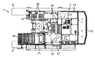
図1は本発明の一実施形態に係る建設機械の全体構造を表す左側面図、図2は平面図である。以降、運転席に着いた作業者の前側(図2中の左側)、後側(同右側)、左側(同下側)、右側(同上側)を建設機械の前、後、左、右とし、それぞれ単に前側、後側、左側、右側と記載する。なお、図2においては、繁雑防止のため後述する作業機3を図示省略してある。クレーン等の他の建設機械も発明の適用対象とすることはできるが、図1及び図2では建設機械の代表例として油圧ショベルを図示している。これらの図に示した油圧ショベルは、走行体1、旋回体2及び作業機3を備えている。
1. Construction Machine FIG. 1 is a left side view showing the overall structure of a construction machine according to an embodiment of the present invention, and FIG. 2 is a plan view. After that, the front side (left side in FIG. 2), rear side (same right side), left side (same lower side), and right side (same upper side) of the worker seated in the driver's seat are referred to as front, rear, left, and right of the construction machine. , Respectively, simply described as front side, rear side, left side, and right side. Note that, in FIG. 2, a work machine 3 described later is omitted in order to prevent complication. Although other construction machines such as cranes can be applied to the invention, FIGS. 1 and 2 show a hydraulic excavator as a typical example of construction machines. The hydraulic excavator shown in these drawings includes a traveling body 1, a revolving
2.走行体
走行体1は油圧ショベルの自力走行を可能とする基礎構造体でホイール式の走行体でも良いが本実施形態ではクローラ式の走行体であり、トラックフレーム4、アイドラ5、走行モータ6、スプロケット7及び履帯(クローラ)8等を備えている。トラックフレーム4はセンタフレーム4a及びその両側に連結した平行な一対のサイドフレーム4bにより上方から見てH型に形成されている。両サイドフレーム4bの一端側にはアイドラ5が、他端側にはスプロケット7がそれぞれ回転自在に支持されている。スプロケット7の回転軸には走行モータ6の出力軸が連結されている。走行モータ6は油圧モータである。アイドラ5とスプロケット7の間には無限軌道状の履帯8が掛け回されていて、履帯8をスプロケット7で駆動することによって走行体1が自走する。サイドフレーム4bの上下部には履帯8を内周側から支持する複数の転輪9が回転自在に支持されている。
2. The traveling body 1 is a basic structure that enables the hydraulic excavator to travel by itself, and may be a wheel type traveling body, but in the present embodiment, it is a crawler type traveling body, and includes a
3.旋回体
旋回体2は、旋回フレーム10、運転室11、カウンタウェイト12、機械室(エンジン室)13等を備えている。旋回フレーム10は旋回体2のベースフレームであり、旋回輪14を介してトラックフレーム4のセンタフレーム4aの上部に設けられている。旋回フレーム10には旋回輪14の付近に旋回モータ(不図示)が搭載されており、旋回モータの出力軸が旋回輪14に設けた歯車と噛み合うことで、走行体1に対して旋回体2が旋回する。旋回モータには電動モータを用いることもできるが、本実施形態では油圧モータが用いてある。
3. Revolving structure The revolving
旋回フレーム10の前部には、作業機3の左右方向の一方側(本例では左側)に位置するように運転室11が設置されている。旋回フレーム10における運転室11の後側には、ボンネットカバー13aに覆われた機械室13が設置されている。旋回フレーム10の後端にはカウンタウェイト12が取り付けられている。機械室13には、原動機、原動機で駆動される油圧ポンプ、油圧ポンプから油圧アクチュエータ(後述するブームシリンダ25等)への圧油を制御するコントロールバルブ等の油圧制御装置、熱交換器類、タンク類、各種配管や配線等が収容されている。原動機には電動機を用いることもあるが、本例ではエンジン(内燃機関)を用いている。また、本実施形態は分解しないで輸送できる(一般道路の輸送制限寸法に納められる)中型の建設機械を想定しており、原動機や原動機により駆動されるファンは各1つである。
A driver's
ここで、走行体1の左右両側の側面(サイドフレーム4bの側面)には、乗降時等に作業者が足を掛ける乗降用ステップ15(図1)が設けられている。旋回フレーム10の左右方向における運転室11を設けた側(本例では左側)の側面には、機械室13等に対して側方からアクセスしてメンテナンスをする際の足場となるメンテナンス通路(キャットウォーク)16が設置されている。メンテナンス通路16は、グレーチング、パンチングメタル又はエキスパンドメタル等の複数の貫通孔を有する例えばメッシュ状の板材によって平面視で矩形状に形成されている。メンテナンス通路16は、前記運転室の側部から前記機械室の側部まで延びている。メンテナンス通路16を設けた側の旋回体2の側面(本例では左側面)には、メンテナンス通路16上から旋回体2の上部に上がる際に利用するラダー17が備えられている。ラダー17を上った先、つまり旋回体2の上面には、エンジン等のメンテナンスの際の足場となる滑り止めステップ18(図2)が設けられている。また、旋回フレーム10の運転室11と反対側(本例では右側)の前部にも、旋回体2に上る際に利用するステップ19(図2)が備えられている。更に旋回フレーム10の前面には、運転室11の前側に位置するように例えば運転室11の前窓を清掃したりするための足場である作業フロア20が設けられている。この作業フロア20には、同じレベルで近接したメンテナンス通路16の前部から行き来することができる。
Here, on the left and right side surfaces of the traveling body 1 (side surfaces of the
4.作業機
作業機3は、作業腕21及び作業具であるバケット24を含む多関節型のフロント作業装置である。作業腕21は、ブーム22、アーム23、ブームシリンダ25、アームシリンダ26及びバケットシリンダ27を備えている。ブーム22は旋回体2の前部に上下方向に回動可能に連結され、アーム23はブーム22の先端に、バケット24はアーム23の先端に、それぞれ回動可能に連結されている。ブームシリンダ25は旋回体2及びブーム22に、アームシリンダ26はブーム22及びアーム23に、それぞれ両端が連結されている。バケットシリンダ27は、基端がアーム23に連結される一方、先端がリンクを介してアーム23の先端部及びバケット24に連結されている。ブームシリンダ25、アームシリンダ26及びバケットシリンダ27はいずれも油圧シリンダである。作業具にはバケット24に代えて、グラップルやマグネット、クラムシェルバケット等が用いられることもある。
4. Working Machine The working machine 3 is a multi-joint type front working apparatus including a working
5.運転室サイドパネル
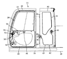
図3は運転室11のドアを周辺構造物と共に表した分解構造図である。図3に示したように、運転室11のボディの乗降側(作業機3と反対側であって本例では左側)の側面を構成するサイドパネルは、前部を構成するドア30と後部を構成する後部パネル40とを含んでいる。なお、図3ではサイドパネルの各アウタパネルを透視してパネルの内部構造を表している。
5. Driver's cab side panel FIG. 3 is an exploded structural view showing the door of the driver's
・ドア
ドア30は運転室11の乗降口を開閉する扉であり、ドアフレーム31、インナパネル32、アウタパネル(不図示)、窓枠33、窓34、ドア開閉装置50を備えている。ドアフレーム31には、上部と下部に運転室11内の運転席(不図示)に座った作業者の視界を確保するための開口(不図示)が上半部及び下半部に設けられている。またドアフレーム31の前部の上下方向の中央部にはドア開閉装置50を配置するための開口(不図示)が設けられている。ドアフレーム31の上半部の開口には防水シールを介して窓枠33が嵌め込まれ、ガラスやアクリル等の透明な板で形成された前後にスライドして開閉する窓34が窓枠33で支持されている。ドアフレーム31の下部にはインナパネル32が取り付けられている。ドア開閉装置50はインナパネル32とドアフレーム31の間に支持されている。インナパネル32の外側(左側)は図示しないアウタパネルで覆われている。ドア30は後縁が上下のヒンジ35を介して後部パネル40に回動自在に連結され(図3ではヒンジ35とドア30とを離して図示している)、後部パネル40に対してヒンジ35を介して前部が水平方向に回動して開閉するようにている。
Door The
・後部パネル
後部パネル40は、上下方向の中央部から上半部に視界確保用の窓41を備えている他、窓41よりも下側の下半部に開ロック装置42を備えている。開ロック装置42はドア30を全開状態(閉じた状態から180度開いた状態)で保持する機構であり、ラッチ部43及び開ロック解除レバー44を備えている。ドア30の凡そ中央部(インナパネル32における窓34の下縁付近)にはリング状の掛け金45が固定されており、ドア30が全開になると掛け金45に対応する位置(この例では後部パネル40の後部で上下方向中央部)にラッチ部43は配置されている。ラッチ部43はバネで付勢された外れ止め(不図示)を備えた空錠であり、後部パネル40の外壁に露出している。ドア30が全開状態になるとドア30に設けた掛け金45がラッチ部43の外れ止めに掛かり、ドア30が全開状態で保持される構成である。開ロック解除レバー44は、後部パネル40の前縁部の上下方向の中央部から前方に運転室11の室内に突出するよう設置されている。この開ロック解除レバー44は作動レバー46とワイヤ47を介してラッチ部43の外れ止めに連結されており、開ロック解除レバー44を操作することによってラッチ部43から掛け金45が外れてドア30が閉じられるようになる。
Rear Panel The
・ドア開閉装置
図4はドア開閉装置を抜き出して表した構造図、図5はドア開閉装置の要部構造を抜き出して表した模式図である。ドア開閉装置50はドア30の開閉に用いる機構であり、ラッチ機構51、内ノブ機構52、第1外ノブ機構53及び第2外ノブ機構54を備えている。
Door Opening/Closing Device FIG. 4 is a structural view showing the door opening/closing device extracted, and FIG. 5 is a schematic view showing a main part structure of the door opening/closing device extracted. The door opening/
ラッチ機構51はドア30を閉じた状態で保持する空錠であり、ドア30の前縁における上下方向の中央部に設置されている。ラッチ機構51は図5に示したように本体55とフック56からなっている。図4ではフック56はラッチ機構51のハウジング58に隠れている。ハウジング58はドア30のインナパネル32に固定されたブラケット62に固定されている。本体55はブラケット62及びハウジング58の少なくとも一方に左右に延びるピン61を介して回転可能に支持されている。また運転室11のボディにはドア30が閉じた状態でラッチ機構51に対応する位置に掛け金63が固定されている。ドア30が完全に閉じるとドア30に設けたラッチ機構51が掛け金63に掛かり、ドア30が閉じた状態で保持される構成である。
The
・内ノブ機構
内ノブ機構52は、本体65、インナハンドルレバー66及びリンク67を備えている。内ノブ機構52の本体65は左右に延びるピン68を介してブラケット62に回転自在に取り付けられている。インナハンドルレバー66は運転室11内の運転席に座った作業者が例えば降車のためにドア30を開ける際に用いる操作部であり、本体65に固定されて運転室11の室内に突出している。またインナハンドルレバー66は、ドア30における窓34の下縁付近において窓34の前後方向の中央よりも前寄りの位置に配置されている。リンク67は内ノブ機構52の本体65とラッチ機構51の本体55の間に位置し、左右に延びるピン69を介してブラケット62に回転自在に取り付けられている。リンク67のピン69を挟んだ両側のうちの一方側はピン71を介してラッチ機構51の本体55に連結されている。リンク67の他方側には長穴72が設けられており、この長穴72の内側に本体65のピン73が収まることで、リンク67は内ノブ機構52の本体65にも連結されている。インナハンドルレバー66を後方に引いて本体65が回転すると、本体65に連動してリンク67が図5に矢印で示したように回転し、ラッチ機構51のフック56が掛け金63から外れ、ドア30が開けられるようになる。
-Inner Knob Mechanism The
・第1外ノブ機構
第1外ノブ機構53は、作動レバー75、第1アウタハンドルレバー76及びケーブル77を備えている。作動レバー75はドア30のインナパネル32に固定されたブラケット78に対し、上下に延びるピン79を介して回動可能に取り付けられている。作動レバー75は、つる巻きばね等の付勢手段(不図示)により後方に延びる姿勢(ロック姿勢)に付勢されている。第1アウタハンドルレバー76は作業者が乗車時等に地上側からドア30を開く際に利用する操作部であり、作動レバー75に固定されてドア30の外壁に露出している。また第1アウタハンドルレバー76はドア30の外側面における前方下部に配置されている。作動レバー75のピン79を挟んで第1アウタハンドルレバー76と反対側の端部は、ケーブル77を介してラッチ機構51の本体55に連結されている。第1アウタハンドルレバー76を前方に引いて作動レバー75が回動すると、ケーブル77に引っ張られてラッチ機構51の本体55が図5に矢印で示したように回転し、ラッチ機構51のフック56が掛け金63から外れ、ドア30が開けられるようになる。
First Outer Knob Mechanism The first
・第2外ノブ機構
第2外ノブ機構54は、作動レバー81、第2アウタハンドルレバー82及びケーブル83を備えている。作動レバー81は上記ブラケット62に対し、上下に延びるピン84を介して回動可能に取り付けられている。作動レバー81は、つる巻きばね等の付勢手段(不図示)により後方に延びる姿勢(ロック姿勢)に付勢されている。第2アウタハンドルレバー82は作業者が乗車時等にメンテナンス通路16の上からドア30を開く際に利用する操作部であり、作動レバー81に固定されてドア30の外壁に露出している。また第2アウタハンドルレバー82は、ドア30の外側面の上下方向の中央部における前後方向の中央部よりも前方寄りの位置に配置されている。第2アウタハンドルレバー82は、ドア30の外側面における第1アウタハンドルレバー76よりも高位置に設けられており、本実施形態ではドアフレーム31における窓枠33とインナパネル32の間の位置に窓枠33に沿って取り付けられている。作動レバー81のピン84を挟んで第2アウタハンドルレバー82と反対側の端部は、ケーブル83を介してラッチ機構51の本体55に連結されている。第2アウタハンドルレバー82を前方に引いて作動レバー81が回動すると、ケーブル83に引っ張られてラッチ機構51の本体55が図5に矢印で示したように回転し、ラッチ機構51のフック56が掛け金63から外れ、ドア30が開けられるようになる。
Second outer knob mechanism The second
・その他
図4に示したように、本実施形態では第1アウタハンドルレバー76を設置したブラケット78に施錠用キーシリンダ90が設置してある。施錠用キーシリンダ90はロッド91を介して連結部材92に連結されている。施錠用キーシリンダ90で施錠操作をすると、連結部材92によりラッチ機構51の本体55が拘束され、ラッチ機構51の動きが制限される構成である。
-Others As shown in FIG. 4, in the present embodiment, the locking
6.作用
作業者が運転室11の内部からドア30を開ける場合、インナハンドルレバー66を後方へ引く。これによって内ノブ機構52の本体65がピン68を中心に回転し、リンク67を介してラッチ機構51の本体55が連動し掛け金63が解放され、ドア30を開けられるようになる。
6. When the operator opens the
作業者が運転室11の外部で地上からドア30を開ける場合、必要に応じて乗降用ステップ15や履帯8等を足場として、第1アウタハンドルレバー76に手が届く高さまで上る。第1アウタハンドルレバー76を引くと、作動レバー75がピン79を中心に回動し、ケーブル77で引っ張られてラッチ機構51の本体55が回転し、掛け金63が解放される。作業者は自身が運転室11に乗り込める程度までドア30を開け、運転室11に乗り込む。
When the operator opens the
また作業者が運転室11の外部でメンテナンス通路16からドア30を開ける場合、第2アウタハンドルレバー82を引く。第2アウタハンドルレバー82を引くと、作動レバー81がピン84を中心に回動し、ケーブル83で引っ張られてラッチ機構51の本体55が回転し、掛け金63が解放される。作業者はそのままドア30を全開にしてメンテナンス通路16を通って前方に移動し、乗降口から運転室11に乗り込んで開ロック解除レバー44を操作してドア30を閉める。
Further, when the operator opens the
以上のように本実施形態におけるドア30は、第1外ノブ機構53及び第2外ノブ機構54のいずれでも開閉操作を行うことができるように構成されている。そのため、通常通り地上から乗車できることは勿論のこと、運転室11の側方に設置した狭隘なメンテナンス通路16の上からでも安定した姿勢で容易に乗車することができる。
As described above, the
また、運転席に沿わった作業者の視界を広く確保するためドア30の少なくとも上半部は大きな窓34になっている。従ってドア30の上半部にドアノブを追加することは難しい。そのようなレイアウトの制約下において、本実施形態では窓枠33の下縁に沿うようにドアフレーム31に設置した。これにより、メンテナンス通路16に立った作業者が必要以上に腰を落とさなくても手が掛けられる位置に第2アウタハンドルレバー82を配置することができる。窓34に掛からないようにドアフレーム31に第2アウタハンドルレバー82を設置したので、第2アウタハンドルレバー82が窓34からの視界を妨げることもない。
Further, at least the upper half portion of the
また、旋回フレーム10の前面に運転室11の前側に位置する作業フロア20を設けたことにより、作業者は作業フロア20からでも第2アウタハンドルレバー82を操作することができる。この場合、メンテナンス通路16上でドア30を開ける場合、ドア30で通路が塞がれるため一端全開にしてドア30を通り越す必要があるが、作業フロア20を利用してドア30を開ける場合にはそのような工程を経る必要がない。
Further, by providing the
1…走行体、2…旋回体、3…作業機、10…旋回フレーム、11…運転室、13…機械室、16…メンテナンス通路、20…作業フロア、30…ドア、31…ドアフレーム、32…インナパネル、33…窓枠、53…第1外ノブ機構、54…第2外ノブ機構 DESCRIPTION OF SYMBOLS 1... Running body, 2... Revolving structure, 3... Working machine, 10... Revolving frame, 11... Operator room, 13... Machine room, 16... Maintenance passage, 20... Work floor, 30... Door, 31... Door frame, 32 ... Inner panel, 33... Window frame, 53... First outer knob mechanism, 54... Second outer knob mechanism
Claims (3)
前記第1外ノブ機構及び前記第2外ノブ機構のいずれでも前記ドアが開閉可能に構成されており、
前記内ノブ機構は、
前記インナパネルに固定されたブラケットに回転自在に取り付けられた本体と、
前記窓枠の下縁付近において前記窓枠の前後方向の中央よりも前寄りの位置に配置され、前記本体に固定されて前記運転室の室内に突出したインナハンドルレバーと、
前記本体と前記ラッチ機構との間に位置して前記ブラケットに回転自在に取り付けられ、一方側が前記ラッチ機構に、他方側が前記本体に連結されたリンクとを備え、
前記インナハンドルレバーを引いて前記本体が回転すると、前記本体に連動して前記リンクが回転し、前記ラッチ機構が作動して前記ドアが開くように構成されており、
前記第2外ノブ機構は、
前記ブラケットに回動可能に取り付けられ、ケーブルを介して前記ラッチ機構に連結されると共に、付勢手段により後方に延びる姿勢に付勢された作動レバーと、
前記ドアの外側面における前記窓枠と前記インナパネルの間の位置で前後方向の中央部よりも前方寄りに位置し、前記作動レバーに固定されて前記ドアの外壁に露出した第2アウタハンドルレバーとを備え、
前記第2アウタハンドルレバーを前方に引いて前記作動レバーが回動すると、前記ケーブルに引っ張られて前記ラッチ機構が作動して前記ドアが開くように構成されている
ことを特徴とする建設機械。 A traveling body, a revolving structure installed on the upper portion of the traveling structure, and a work machine installed on the front part of the revolving structure, wherein the revolving structure is a revolving frame that is a base frame, and a front part of the revolving frame. A cab arranged, a machine room arranged behind the cab in the swivel frame, and a maintenance passage attached to the swivel frame and extending from a side part of the cab to a side part of the machine room. door of the cab, the door frame, window frame attached to an upper portion of the door frame, before Symbol inner panel attached to the lower part of the door frame, and has a door opening and closing device, the door opening and closing device Is a latch mechanism, an inner knob mechanism, a first outer knob mechanism provided at a lower portion outside the door, and a second outer knob mechanism provided at a position higher than the first outer knob mechanism on the outer side of the door. In a construction machine equipped with
The door can be opened and closed by either the first outer knob mechanism or the second outer knob mechanism,
The inner knob mechanism is
A main body rotatably attached to a bracket fixed to the inner panel,
An inner handle lever, which is disposed near the lower edge of the window frame and is located at a position closer to the front than the center in the front-rear direction of the window frame, is fixed to the main body, and protrudes into the cabin of the cab
A link that is positioned between the main body and the latch mechanism and is rotatably attached to the bracket, and one side of the link is connected to the latch mechanism and the other side is linked to the main body;
When the inner handle lever is pulled to rotate the main body, the link is interlocked with the main body to operate the latch mechanism to open the door,
The second outer knob mechanism,
An operating lever that is rotatably attached to the bracket, is connected to the latch mechanism via a cable, and is biased by a biasing means in a posture extending rearward;
A second outer handle lever, which is located between the window frame and the inner panel on the outer side surface of the door, is located closer to the front than the central portion in the front-rear direction, and is fixed to the operating lever and exposed to the outer wall of the door. With and
When the second outer handle lever is pulled forward to rotate the operating lever, the cable is pulled and the latch mechanism is operated to open the door. Construction machinery.
Priority Applications (1)
| Application Number | Priority Date | Filing Date | Title |
|---|---|---|---|
| JP2017051048A JP6712558B2 (en) | 2017-03-16 | 2017-03-16 | Construction machinery |
Applications Claiming Priority (1)
| Application Number | Priority Date | Filing Date | Title |
|---|---|---|---|
| JP2017051048A JP6712558B2 (en) | 2017-03-16 | 2017-03-16 | Construction machinery |
Publications (3)
| Publication Number | Publication Date |
|---|---|
| JP2018154984A JP2018154984A (en) | 2018-10-04 |
| JP2018154984A5 JP2018154984A5 (en) | 2019-03-28 |
| JP6712558B2 true JP6712558B2 (en) | 2020-06-24 |
Family
ID=63716304
Family Applications (1)
| Application Number | Title | Priority Date | Filing Date |
|---|---|---|---|
| JP2017051048A Active JP6712558B2 (en) | 2017-03-16 | 2017-03-16 | Construction machinery |
Country Status (1)
| Country | Link |
|---|---|
| JP (1) | JP6712558B2 (en) |
Families Citing this family (2)
| Publication number | Priority date | Publication date | Assignee | Title |
|---|---|---|---|---|
| JP7423493B2 (en) | 2020-11-13 | 2024-01-29 | プレス工業株式会社 | Construction machinery cabin door structure |
| CN116113593A (en) | 2021-03-18 | 2023-05-12 | 日立建机株式会社 | Engineering machinery |
-
2017
- 2017-03-16 JP JP2017051048A patent/JP6712558B2/en active Active
Also Published As
| Publication number | Publication date |
|---|---|
| JP2018154984A (en) | 2018-10-04 |
Similar Documents
| Publication | Publication Date | Title |
|---|---|---|
| US6170588B1 (en) | Revolving construction machine | |
| JP2009241817A (en) | Door device of small vehicle | |
| ITMI20000445A1 (en) | OSCILLATING TYPE WORK VEHICLE | |
| CN108138462B (en) | Small construction machine | |
| JP6712558B2 (en) | Construction machinery | |
| JP2018048470A (en) | Construction machine | |
| JP6075401B2 (en) | Construction machinery | |
| EP3719215B1 (en) | Work machine cab and work machine | |
| JP5785128B2 (en) | Manual storage structure in the operating section of a swing work machine | |
| JP2007285003A (en) | Construction machinery | |
| JP5054802B2 (en) | Construction machinery | |
| JP4673269B2 (en) | Construction machinery | |
| JP2004190276A (en) | Handrail in construction machine | |
| JP3178386B2 (en) | Revolving superstructure of construction equipment | |
| JP3772545B2 (en) | Driver's seat unit for construction machinery | |
| JP2009243189A (en) | Door device of small vehicle | |
| JP2004257000A (en) | Battery mounting device for construction machine and construction machine | |
| JP3576832B2 (en) | Turning work machine | |
| JP6369495B2 (en) | Work machine | |
| JP6920265B2 (en) | Construction machinery | |
| JP2004156334A (en) | Working machine | |
| JP2006056375A (en) | Construction machine | |
| JP2005163533A (en) | Working machine | |
| JP2021080640A (en) | Construction machine | |
| JP2001163268A (en) | Exterior cover device for apparatus equipped with engine |
Legal Events
| Date | Code | Title | Description |
|---|---|---|---|
| A521 | Written amendment |
Free format text: JAPANESE INTERMEDIATE CODE: A523 Effective date: 20190208 |
|
| A621 | Written request for application examination |
Free format text: JAPANESE INTERMEDIATE CODE: A621 Effective date: 20190208 |
|
| A977 | Report on retrieval |
Free format text: JAPANESE INTERMEDIATE CODE: A971007 Effective date: 20191114 |
|
| A131 | Notification of reasons for refusal |
Free format text: JAPANESE INTERMEDIATE CODE: A131 Effective date: 20191126 |
|
| A521 | Written amendment |
Free format text: JAPANESE INTERMEDIATE CODE: A523 Effective date: 20200121 |
|
| TRDD | Decision of grant or rejection written | ||
| A01 | Written decision to grant a patent or to grant a registration (utility model) |
Free format text: JAPANESE INTERMEDIATE CODE: A01 Effective date: 20200519 |
|
| A61 | First payment of annual fees (during grant procedure) |
Free format text: JAPANESE INTERMEDIATE CODE: A61 Effective date: 20200601 |
|
| R150 | Certificate of patent or registration of utility model |
Ref document number: 6712558 Country of ref document: JP Free format text: JAPANESE INTERMEDIATE CODE: R150 |