JP2004156334A - Working machine - Google Patents
Working machine Download PDFInfo
- Publication number
- JP2004156334A JP2004156334A JP2002323728A JP2002323728A JP2004156334A JP 2004156334 A JP2004156334 A JP 2004156334A JP 2002323728 A JP2002323728 A JP 2002323728A JP 2002323728 A JP2002323728 A JP 2002323728A JP 2004156334 A JP2004156334 A JP 2004156334A
- Authority
- JP
- Japan
- Prior art keywords
- upper revolving
- seat
- peripheral portion
- driver
- frame
- Prior art date
- Legal status (The legal status is an assumption and is not a legal conclusion. Google has not performed a legal analysis and makes no representation as to the accuracy of the status listed.)
- Pending
Links
Images


Abstract
Description
【0001】
【発明の属する技術分野】
本発明は、上部旋回体の異なる仕様に対して多くの共通の部品を使用可能とした作業機械に関する。
【0002】
【従来の技術】
従来、作業機械として油圧ショベルは、自走可能な下部走行体、およびこの下部走行体の上部に旋回可能に設けられた上部旋回体を備え、上部旋回体上には運転席が設置されている。そして、油圧ショベルには、運転席を覆うキャブを備えた仕様やキャノピを備えた仕様などがある。
【0003】
比較的大型および中型の油圧ショベルの場合には、上部旋回体の前側に配置される運転席に対してエンジンや燃料タンクなどが上部旋回体の後側に配置され、運転席周りに比較的余裕があるため、大きさおよび形状の同じ共通のキャブを上部旋回体に取り付けられるように構成し、キャブの共通化が図られていることが多い。
【0004】
比較的小型の油圧ショベルでは、上部旋回体の両側および後側にわたる周辺形状を円形とし、この上部旋回体の旋回範囲を下部走行体の外形範囲内とした小旋回型の油圧ショベルがある。この油圧ショベルの場合、運転席周りにエンジンや燃料タンクなどが接近して配置されるため、共通のキャブをそのまま取り付けることが困難で、運転席周りでキャブが干渉する部分を切断するなどの加工を加えて上部旋回体に取り付けている(例えば、特許文献1参照)。
【0005】
【特許文献1】
特開平9−316931号公報(第1頁ないし第4頁、図1ないし図17)
【0006】
【発明が解決しようとする課題】
ところで、例えば市街地の小路などでの油圧ショベルによる作業を可能とするために、これまでの小型の油圧ショベルよりもより小型の油圧ショベルを求める要望がある。しかし、油圧ショベルをより小型化した場合、上部旋回体が小さくなり、この上部旋回体の運転席には共通のキャブを取り付けること自体がスペース的に困難となる。
【0007】
そこで、より小型化した油圧ショベルにおいて、共通のキャブを使用することを目的とした場合、上部旋回体のみを共通のキャブが取り付けられるように大きさを変更した仕様を作ることが考えられるが、従来の小型の油圧ショベルのように周辺形状が円形の上部旋回体の大きさを変更するには、上部旋回体の内部の旋回フレームなどとともに外側の配置される例えば燃料タンクやカバーなど含めて多くの部品を変更しなければならず、上部旋回体の異なる仕様での部品の共通化が難しい問題がある。
【0008】
本発明は、このような点に鑑みなされたもので、上部旋回体の異なる仕様に対して多くの部品を共通化できる作業機械を提供することを目的とする。
【0009】
【課題を解決するための手段】
請求項1に記載された発明は、下部走行体と、下部走行体に対して旋回可能に設けられ、両側部が前後方向に直線状で両側部から後部にわたって略U字形に形成された周辺部を有する上部旋回体と、上部旋回体上で周辺部の内側に設けられた運転席と、上部旋回体内に設けられたエンジンと、上部旋回体の周辺部に設けられエンジンに供給する燃料を貯溜する燃料タンクと、上部旋回体の周辺部に設けられ上部旋回体の内側を開閉するカバーとを具備した作業機械であり、上部旋回体を、両側部が前後方向に直線状で両側部から後部にわたって略U字形に形成された周辺部を有する形状とし、この周辺部に燃料タンクやカバーを設けた構造を採用したため、例えば上部旋回体の前後方向の長さが異なる仕様の場合でも、上部旋回体の周辺部の両側部は直線状のまま形状変更がなく、周辺部に設けられる燃料タンクやカバーなどはそのまま使用でき、したがって、上部旋回体の異なる仕様に対して多くの部品を共通化できる。
【0010】
請求項2に記載された発明は、請求項1記載の作業機械において、エンジンは、上部旋回体の運転席の下側に設けられたものであり、運転席に対して上部旋回体の両側部が前後方向に直線状で両側部から後部にわたって略U字形に形成された周辺部を実現できる。
【0011】
請求項3に記載された発明は、請求項1または2記載の作業機械において、上部旋回体上で周辺部の内側に取り付けられたキャブを備えたものであり、例えば別の機種と共通のキャブを前後方向の長さが異なる仕様の上部旋回体上で周辺部の内側に取り付けることができる。
【0012】
請求項4に記載された発明は、請求項1または2記載の作業機械において、上部旋回体上で周辺部の内側に取り付けられたキャノピを備えたものであり、例えば別の仕様と共通のキャノピを前後方向の長さが異なる仕様の上部旋回体上で周辺部の内側に取り付けることができる。
【0013】
【発明の実施の形態】
以下、本発明に係る実施の形態を図1乃至図8を参照して説明する。
【0014】
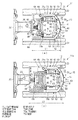
図1(a)、図2ないし図4に、キャノピ専用である第1の仕様の小旋回型の作業機械としての油圧ショベル11を示す。この油圧ショベル11は、自走可能な下部走行体12の上側に旋回軸部13を介して第1の仕様の上部旋回体14が旋回可能に取り付けられている。これら下部走行体12、旋回軸部13および上部旋回体14により作業機械本体15が構成されている。
【0015】
下部走行体12は、上面に旋回軸部13を取り付けた走行機台19を有し、この走行機台19の両側に自走可能な履帯20を有する走行装置21が取り付けられている。各走行装置21は、履帯20を回動させる流体圧作動装置としての油圧モータである図示しない走行モータを備えている。
【0016】
下部走行体12の走行機台19の前側には、下部走行体12の走行方向に交差する方向を長手方向とした略矩形状のブレード22が上下動可能に取り付けられている。このブレード22は、流体圧作動装置としての油圧シリンダである図示しないブレードシリンダにより上下動される。
【0017】
また、上部旋回体14は、両側部が前後方向に直線状かつ平行で後部が湾曲状とする周辺形状に形成され、この上部旋回体14の旋回範囲が下部走行体12の外形範囲内で下部走行体12より前後方向や左右の両側方向に突出しない小旋回型に構成されている。上部旋回体14は、下部走行体12に旋回軸部13を介して取り付けられた旋回フレーム25を有し、この旋回フレーム25には、上部旋回体14を下部走行体12に対して水平に旋回させる流体圧作動装置としての油圧モータである図示しない旋回用モータが取り付けられている。
【0018】
旋回フレーム25の前側には、上部旋回体14から前方に向けて突出した平面視略三角形状の連結突部26が設けられている。この連結突部26の先端部には、掘削作業用の作業装置27が取り付けられている。この作業装置27は、この作業装置27を動作させるための複数の流体圧作動装置としての油圧シリンダ28,29,30などを備えている。
【0019】
旋回フレーム25上の後部には、上部旋回体14の前側よりも上方に突出する動力装置収容部31が設けられている。この動力装置収容部31は、この動力装置収容部31の枠体となる座席用フレーム32を備えている。この座席用フレーム32は、上部の枠部33を備えており、この枠部33は旋回フレーム25に対して立設された複数の脚部34の上端に支持されている。座席用フレーム32は、上部旋回体14の周辺形状に対応して、両側部が前後方向に直線状かつ平行で後部が湾曲状に形成されている。
【0020】
旋回フレーム25上の後側で座席用フレーム32の内側には、エンジン35、このエンジン35からの排気に伴う排気音を消音させるマフラ36、エンジン35にて駆動されて作動流体としての作動油を加圧供給する流体圧ポンプとしての図示しない油圧ポンプ、この油圧ポンプにて循環される作動油を貯溜する作動流体タンクとしての作動油タンク37、油圧ショベル11の計器やエンジン35などへ電力を供給する図示しないバッテリなどが配置されている。
【0021】
旋回フレーム25上の前側には、図示しないコントロールバルブが取り付けられている。このコントロールバルブは、上述した各流体圧作動装置のそれぞれに対して油圧ポンプから加圧供給させる作動油を制御し、各流体圧作動装置で対応した各機構を作動させる。
【0022】
座席用フレーム32の上側部には、油圧ショベル11を運転および操作する作業者であるオペレータが座る座席としての運転席40が取り付けられている。この運転席40は、座席用フレーム32の上側部に位置する座板部41を備えており、この座板部41には、この座板部41に座ったオペレータの背凭れとなる背凭部42が角度調整可能に取り付けられている。この座板部41は、座席用フレーム32の枠部33の後側に取り付けられた図示しないヒンジによって、この座板部41の後端部を中心としてこの座板部41が後方に向けて回動可能とされている。この座板部41を後方に向けて回動させることにより、座席用フレーム32の枠部33の内側に形成されている図示しない開口部が開口され、すなわち動力装置収容部31の上面が開口される。
【0023】
運転席40の両側には、この運転席40に座ったオペレータの肘掛部となるコンソール部としての一対のコンソールボックス43がそれぞれ設けられている。これら一対のコンソールボックス43は、座席用フレーム32の枠部33の両側上面に取り付けられている。これら一対のコンソールボックス43の上側部には、表示部や、スイッチとしてのダイヤル式アクセレータ、スタータスイッチおよびライトスイッチなどを備えた操作パネル44が取り付けられている。一対のコンソールボックス43の前側の上側部には、作業装置27を操作する操作器としての一対の操作レバー45が取り付けられている。
【0024】
旋回フレーム25上の運転席40より前側には運転席40に座ったオペレータの足を置くフロアプレート46が取り付けられ、このフロアプレート46の前側に下部走行体12による走行を操作するペダル47が取り付けられている。
【0025】
これら操作レバー45およびペダル47の操作により、コントロールバルブから上述した各流体圧作動装置のそれぞれに対して加圧供給させる作動油を制御し、各流体圧作動装置で対応した各機構を作動させる。
【0026】
座席用フレーム32の両側面には枠部33と前後の脚部34との間を通じて開口する両側の開口部50が形成され、これら両側の開口部50にはサイドカバーである両側のカバー51がそれぞれ開閉可能に取り付けられている。これら両側のカバー51は、前側が上部旋回体14の両側の形状に沿って前後方向に直線状で、後側が上部旋回体14の後側に回り込むように湾曲形成されており、開口部50の側面を覆う側面カバー部52およびこの側面カバー部52の上側から座席用フレーム32の枠部33側に湾曲された上面カバー部53を有している。これら両側のカバー51は、上部旋回体14の両側部に取り付けられたヒンジ54によって外側下方へ向かって下開きに開くように開閉可能に取り付けられ、開口部50を閉塞するように閉じた状態で座席用フレーム32に着脱可能とする図示しないボルトなどによって係止される。
【0027】
座席用フレーム32の後側には枠部33と後側の一対の脚部34との間を通じて開口する後側の開口部55が形成され、この後側の開口部55にはリアカバーであるカバー56が開閉可能に取り付けられている。この後側のカバー56は、略平板状で上部旋回体14の後側の湾曲した形状に沿って湾曲形成しており、開口部55の後面を覆う後面カバー部57およびこの後面カバー部57の上側から座席用フレーム32の枠部33側に湾曲された上面カバー部58を有している。この後側のカバー56は、座席用フレーム32の枠部33に取り付けられたヒンジ59によって後側上方へ向かって上開きに開くように開閉可能に取り付けられ、開口部55を閉塞するように閉じた状態で座席用フレーム32に着脱可能とする図示しないボルトなどによって係止される。
【0028】
座席用フレーム32の前側には枠部33と前側の一対の脚部34との間にて前側の開口部60が形成され、この前側の開口部60にはフロントカバーである平板状のカバー61が開閉可能に取り付けられている。このカバー61は、座席用フレーム32内に収容された主としてバッテリを取り外し可能に覆って保護する。
【0029】
上部旋回体14の座席用フレーム32より前側の一側である右側には、エンジン35に供給する燃料を貯溜する燃料タンク64が取り付けられている。この燃料タンク64には、上部に図示しない給油口が設けられ、この給油口を開閉するキャップ65が着脱可能に取り付けられている。燃料タンク64の側面および上面は一側のカバー51の側面カバー部52および上面カバー部53に連続した面に形成されているとともに上面から前面にわたって湾曲形成されている。
【0030】
上部旋回体14の座席用フレーム32より前側の他側である左側には、オペレータが運転席40に対して乗り降りする乗降部68が形成されている。
【0031】
上部旋回体14の旋回フレーム25の周囲には、両側から前側にわたってフェンダ71がそれぞれ取り付けられ、後側に上部旋回体14の前側に取り付けられた作業装置14との質量バランスをとるためのカウンタウエート72が取り付けられている。
【0032】
そして、上部旋回体14は、両側部75a,75bが前後方向に直線状かつ平行で後部75cが湾曲し両側部75a,75bから後部75cにわたって略U字形に形成された周辺部75を有し、この周辺部75の内側で座席用フレーム32上に運転席40が設けられている。上部旋回体14の周辺部75には、一側部75aに燃料タンク64およびカバー51がそれぞれ設けられ、他側部75bに乗降部68およびカバー51がそれぞれ設けられ、後部75cにカバー56およびカウンタウエート72がなど設けられている。上部旋回体14の周辺部75の両側部75a,75bの幅は略同じ幅に形成されているとともに、後部75cの幅も略同じ幅に形成されている。
【0033】
また、図2および図3に示すように、キャノピ専用である第1の仕様の油圧ショベル11では、運転席40の上方を覆うキャノピ78が取り付けられている。このキャノピ78は、座席用フレーム32の枠部33の上面両側位置に立設される一対のキャノピ支柱79を有し、これらキャノピ支柱79の上端に、運転席40に着席したオペレータを主として上方からの陽射しまたは障害物や落下物から保護するキャノピトップ80が取り付けられている。キャノピ支柱79は、座席用フレーム32の枠部33上で運転席40の両側に設けられる取付部81にボルトなどの締結手段によって着脱可能に取り付けられている。
【0034】
上部旋回体14のフロアプレート46の前側にガード82が立設され、乗降部68の後側で座席用フレーム32にオペレータが乗降する際に握って乗降を容易にする手摺83が取り付けられている。
【0035】
また、図1(b)および図5に、キャノピおよびキャブ兼用である第2の仕様の小旋回型の作業機械としての油圧ショベル11aを示す。この油圧ショベル11aは、上述した第1の仕様の油圧ショベル11の上部旋回体14のみを両側幅は変更なく前後方向にのみ拡大延長するように変更したもので、基本構造は第1の仕様の油圧ショベル11と同一である。第1の仕様の油圧ショベル11の上部旋回体14の前後方向の長さがL1なのに対して、第2の仕様の油圧ショベル11aの上部旋回体14の前後方向の長さがL2で、L1<L2の前後方向の長さ関係にある。これにより、例えば他の大きさの異なる機種の油圧ショベルと大きさおよび形状の同じ共通のキャブ91を使用する場合、第1の仕様の油圧ショベル11では前後方向のスペースが小さいために取り付けることが困難な場合でも、この第2の仕様の油圧ショベル11aでは共通のキャブ91を取り付けることができる。
【0036】
第2の仕様の油圧ショベル11aの上部旋回体14の前後方向への延長は、第1の仕様の油圧ショベル11に対し、主として旋回フレーム25を前後方向に延長し、旋回フレーム25の前側および後側に配設される構造はそのまま前方および後方へそれぞれ移行させることで対応している。したがって、旋回フレーム25の前後方向への延長は、旋回フレーム25の中間部を前後方向に延長した形となる。
【0037】
上部旋回体14は、両側部75a,75bが前後方向に直線状かつ平行で後部75cが湾曲し両側部75a,75bから後部75cにわたって略U字形に形成された周辺部75を有する形状とし、この周辺部75に燃料タンク64、カバー51,56およびカウンタウエート72などを設けた構造を採用しているため、上部旋回体14を前後方向に延長しても、上部旋回体14の周辺部75の直線状の両側部75a,75bは直線状のままで形状変更がない。
【0038】
そのため、第2の仕様の油圧ショベル11aと第1の仕様の油圧ショベル11とで異なる部品は、前後方向の長さがそれぞれ異なる旋回フレーム25、フロアプレート46およびフェンダ71などがあり、さらに、前側のコントロールバルブと後側の油圧ポンプなどとを接続する作動油の配管や、運転席40周りの機器と上部旋回体14内に配置される制御部などとを電気接続するハーネス類などがある。
【0039】
第2の仕様の油圧ショベル11aと第1の仕様の油圧ショベル11とで異なる部品以外は、第2の仕様の油圧ショベル11aと第1の仕様の油圧ショベル11とで共通に使用でき、例えば、エンジン35などを含む駆動関係の構成部品、油圧ポンプや作動油タンク37などを含む油圧回路関係の構成部品、運転席40およびこの運転席40周りの操作系、各カバー51,56、燃料タンク64およびカウンタウエート72などは共通に使用できる。
【0040】
このように、第2の仕様の油圧ショベル11aの上部旋回体14は、両側部75a,75bが前後方向に直線状かつ平行で後部75cが湾曲し両側部75a,75bから後部75cにわたって略U字形に形成された周辺部75を有する形状とし、この周辺部75に燃料タンク64、カバー51,56およびカウンタウエート72などを設けた構造を採用しているため、第2の仕様の油圧ショベル11aに対し、キャブ91を取り付けるために上部旋回体14を前後方向に延長しても、上部旋回体14の周辺部75の両側部75a,75bは直線状のまま形状変更がなく、この周辺部75に設けられる燃料タンク64、カバー51,56およびカウンタウエート72などはそのまま使用でき、したがって、上部旋回体14の異なる第1の仕様と第2の仕様とに対して多くの部品を共通化できる。
【0041】
そして、キャブ91は、箱形のキャブ本体92を有し、このキャブ本体92の前面、両側面および後面にそれぞれ透明な窓部93が形成され、キャブ本体92には乗降部68の位置に対応して乗降口92aが形成され、この乗降口92aに扉体94が開閉可能に取り付けられている。
【0042】
キャブ本体92の下縁は上部旋回体14の周辺部75の内側に配置され、座席用フレーム32の枠部33上で運転席40の両側に設けられる取付部81やフロアプレート46などにボルトなどの締結手段によって着脱可能に取り付けられている。
【0043】
図7および図8に示すように、キャブ本体92の下縁には、上部旋回体14に対するがたつき防止や密閉性の確保のためにパッキング95が取り付けられている。燃料タンク64の部分については、図中にシール位置Sを示すように、この燃料タンク64の上面から前面にわたってパッキング95が接合されてシールされる。燃料タンク64の給油口の部分についてはキャブ本体92の内方に迂回するように湾曲形成されている。したがって、燃料タンク64は、キャブ91の内外の中間に位置し、キャブ91の内外にそれぞれはみ出した構造となっている。
【0044】
なお、キャブ91の場合には、キャノピ78の場合に用いられたガード82や手摺83は上部旋回体14側に取り付けられない。キャブ本体92がガードの機能を有し、キャブ本体92に乗降口92aの側部に手摺96が取り付けられる。
【0045】
また、第2の仕様の油圧ショベル11aでは、キャブ91の他に、図6に示すように、第1の仕様の油圧ショベル11と共通のキャノピ78を周辺部75の内側で座席用フレーム32に取り付けることができる。
【0046】
したがって、本実施の形態によれば、上部旋回体14を、両側部75a,75bが前後方向に直線状かつ平行で後部75cが湾曲し両側部75a,75bから後部75cにわたって略U字形に形成された周辺部75を有する形状とし、この周辺部75に燃料タンク64、カバー51,56およびカウンタウエート72などを設けた構造を採用したため、上部旋回体14の前後方向の長さを異なる第1の仕様および第2の仕様のいずれも、上部旋回体14の周辺部75の両側部75a,75bは直線状のまま形状変更がなく、周辺部75に設けられる燃料タンク64、カバー51,56およびカウンタウエート72などはそのまま使用でき、したがって、上部旋回体14の異なる仕様に対して多くの部品を共通化できる。
【0047】
上部旋回体14上に座席用フレーム32を取り付けてこの座席用フレーム32の上に運転席40を取り付けたことにより、運転席40の下側にエンジン35や作動油タンク37などを配置することができ、そのため、運転席40に対して上部旋回体14の両側部75a,75bが前後方向に直線状かつ平行で後部75cが湾曲し両側部75a,75bから後部75cにわたって略U字形に形成された周辺部75を実現できる。
【0048】
また、キャノピ専用である第1の仕様の油圧ショベル11は、上部旋回体14の前後方向の長さが第2の仕様に比べて短く、上部旋回体14の旋回範囲を第2の仕様に比べてより小さくできる。
【0049】
また、キャノピおよびキャブ兼用である第2の仕様の油圧ショベル11aは、他の機種と大きさ形状の同じ共通のキャブ91を取り付けることができるとともに、キャブ91に代えて第1の仕様と大きさ形状の同じ共通のキャノピ78を取り付けることができ、第1の仕様の油圧ショベル11との部品の共通化を図ることができるとともに、他の機種や仕様のキャブ91やキャノピ78などの部品の共通化を図ることができる。
【0050】
【発明の効果】
請求項1記載の発明によれば、両側部が前後方向に直線状で両側部から後部にわたって略U字形に形成された周辺部を有する上部旋回体の形状とし、この周辺部に燃料タンクやカバーを設けた構造を採用したため、例えば上部旋回体の前後方向の長さが異なる仕様の場合でも、上部旋回体の周辺部の両側部は直線状のまま形状変更がなく、周辺部に設けられる燃料タンクやカバーなどはそのまま使用でき、したがって、上部旋回体の異なる仕様に対して多くの部品を共通化できる。
【0051】
請求項2記載の発明によれば、上部旋回体の運転席の下側にエンジンを設けたため、運転席に対して上部旋回体の両側部が前後方向に直線状で両側部から後部にわたって略U字形に形成された周辺部を実現できる。
【0052】
請求項3記載の発明によれば、上部旋回体上で周辺部の内側には、例えば別の機種と共通のキャブを取り付けることができる。
【0053】
請求項4記載の発明によれば、上部旋回体上で周辺部の内側には、例えば別の仕様と共通のキャノピを取り付けることができる。
【図面の簡単な説明】
【図1】本発明に係る作業機械の一実施の形態を示し、(a)はキャノピ専用である第1の仕様の上部旋回体を備えた作業機械の平面図、(b)はキャノピおよびキャブ兼用である第2の仕様の上部旋回体を備えた作業機械の平面図である。
【図2】同上作業機械の第1の仕様の上部旋回体にキャノピおよび作業装置を取り付けた側面図である。
【図3】同上作業機械の第1の仕様の上部旋回体にキャノピを取り付けた斜視図である。
【図4】同上作業機械の上部旋回体のカバーを開いた斜視図である。
【図5】同上作業機械の第2の仕様の上部旋回体にキャブおよび作業装置を取り付けた側面図である。
【図6】同上作業機械の第2の仕様の上部旋回体にキャノピおよび作業装置を取り付けた側面図である。
【図7】同上作業機械の燃料タンクに対するキャブのシール位置を示す斜視図である。
【図8】同上作業機械の燃料タンクに対するキャブの取付状態を示す断面図である。
【符号の説明】
11,11a 作業機械としての油圧ショベル
12 下部走行体
14 上部旋回体
35 エンジン
40 運転席
51,56 カバー
64 燃料タンク
75 周辺部
75a,75b 側部
75c 後部
78 キャノピ
91 キャブ[0001]
TECHNICAL FIELD OF THE INVENTION
TECHNICAL FIELD The present invention relates to a work machine that can use many common parts for different specifications of an upper-part turning body.
[0002]
[Prior art]
2. Description of the Related Art Conventionally, a hydraulic shovel as a working machine includes a lower traveling body capable of self-propelling, and an upper revolving body rotatably provided above the lower traveling body, and a driver's seat is provided on the upper revolving body. . Hydraulic excavators include a specification having a cab that covers a driver's seat and a specification including a canopy.
[0003]
In the case of relatively large and medium-sized hydraulic excavators, the engine, fuel tank, etc. are arranged behind the upper revolving structure with respect to the driver's seat arranged in front of the upper revolving structure, so that there is relatively room around the driver's seat. Therefore, in many cases, a common cab having the same size and shape is configured to be attached to the upper swing body, and the cab is commonly used.
[0004]
2. Description of the Related Art A relatively small hydraulic shovel is a small slewing type excavator in which a peripheral shape on both sides and a rear side of an upper slewing body is circular, and a slewing range of the upper slewing body is within an outer range of a lower traveling body. In the case of this excavator, since the engine and fuel tank are placed close to the driver's seat, it is difficult to install a common cab as it is, and processing such as cutting off the part where the cab interferes around the driver's seat (See, for example, Patent Document 1).
[0005]
[Patent Document 1]
JP-A-9-316931 (
[0006]
[Problems to be solved by the invention]
By the way, there is a demand for a hydraulic excavator that is smaller than a conventional small hydraulic excavator in order to enable a hydraulic excavator to work on an alley in an urban area. However, when the hydraulic excavator is further miniaturized, the size of the upper revolving structure becomes smaller, and it is difficult to attach a common cab to the driver's seat of the upper revolving structure in terms of space.
[0007]
Therefore, if the purpose is to use a common cab in a more miniaturized hydraulic excavator, it is conceivable to create a specification in which the size is changed so that only the upper slewing body can be attached to the common cab, To change the size of an upper revolving unit with a circular shape like a conventional small hydraulic excavator, it is often necessary to include a revolving frame inside the upper revolving unit and the outside, for example, a fuel tank and a cover. Of the upper revolving unit, and it is difficult to share parts with different specifications of the upper structure.
[0008]
The present invention has been made in view of such a point, and an object of the present invention is to provide a work machine that can use many parts in common for different specifications of an upper-part turning body.
[0009]
[Means for Solving the Problems]
The invention described in
[0010]
According to a second aspect of the present invention, in the working machine according to the first aspect, the engine is provided below the driver's seat of the upper revolving unit, and both sides of the upper revolving unit with respect to the driver's seat. Can be realized in a substantially U-shaped peripheral portion which is linear in the front-rear direction and extends from both sides to the rear.
[0011]
According to a third aspect of the present invention, there is provided the working machine according to the first or second aspect, further including a cab mounted on an inner side of a peripheral portion on the upper rotating body. Can be attached to the inside of the peripheral portion on the upper revolving structure with different lengths in the front-rear direction.
[0012]
According to a fourth aspect of the present invention, there is provided the working machine according to the first or second aspect, further comprising a canopy mounted inside the peripheral portion on the upper rotating body. Can be attached to the inside of the peripheral portion on the upper revolving structure with different lengths in the front-rear direction.
[0013]
BEST MODE FOR CARRYING OUT THE INVENTION
An embodiment according to the present invention will be described below with reference to FIGS.
[0014]
FIG. 1A and FIGS. 2 to 4 show a
[0015]
The
[0016]
On the front side of the
[0017]
The upper revolving
[0018]
On the front side of the revolving
[0019]
At a rear portion on the revolving
[0020]
On the rear side of the revolving
[0021]
A control valve (not shown) is attached to the front side of the turning
[0022]
A driver's
[0023]
On both sides of the driver's
[0024]
A
[0025]
By the operation of the
[0026]
Both sides of the
[0027]
A
[0028]
On the front side of the
[0029]
A
[0030]
On the left side, which is the other side in front of the
[0031]
A
[0032]
The
[0033]
In addition, as shown in FIGS. 2 and 3, in the
[0034]
A
[0035]
FIGS. 1B and 5 show a
[0036]
The extension of the upper revolving
[0037]
The upper revolving
[0038]
Therefore, parts that differ between the
[0039]
Except for the parts that are different between the
[0040]
As described above, the
[0041]
The
[0042]
The lower edge of the
[0043]
As shown in FIGS. 7 and 8, a packing 95 is attached to the lower edge of the cab
[0044]
In the case of the
[0045]
In addition, in the
[0046]
Therefore, according to the present embodiment, upper revolving
[0047]
By mounting the
[0048]
Further, in the
[0049]
In addition, the
[0050]
【The invention's effect】
According to the first aspect of the present invention, the upper revolving structure has a peripheral portion having both sides linearly formed in the front-rear direction and formed substantially in a U-shape from both sides to the rear. For example, even in the case of specifications in which the length of the upper revolving structure in the front-rear direction is different, both sides of the peripheral portion of the upper revolving structure remain linear and have no shape change, and the fuel provided in the peripheral portion is provided. The tank and the cover can be used as they are, so that many parts can be shared for different specifications of the upper swing body.
[0051]
According to the second aspect of the present invention, since the engine is provided below the driver's seat of the upper revolving structure, both sides of the upper revolving structure are linear in the front-rear direction with respect to the driver's seat, and are substantially U from both sides to the rear. A peripheral portion formed in a letter shape can be realized.
[0052]
According to the third aspect of the present invention, for example, a cab common to another model can be mounted inside the peripheral portion on the upper swing body.
[0053]
According to the fourth aspect of the present invention, for example, a canopy common to different specifications can be attached to the inside of the peripheral portion on the upper swing body.
[Brief description of the drawings]
1A and 1B show an embodiment of a working machine according to the present invention, wherein FIG. 1A is a plan view of a working machine having an upper revolving structure of a first specification dedicated to a canopy, and FIG. 1B is a canopy and a cab. It is a top view of the working machine provided with the upper revolving superstructure of the 2nd specification which is shared.
FIG. 2 is a side view of the work machine in which a canopy and a working device are attached to an upper revolving superstructure of a first specification.
FIG. 3 is a perspective view in which a canopy is attached to an upper revolving superstructure of the first specification of the work machine;
FIG. 4 is a perspective view of the work machine in which a cover of an upper swing body is opened.
FIG. 5 is a side view of the work machine in which a cab and a working device are attached to an upper revolving superstructure of a second specification.
FIG. 6 is a side view of the work machine in which a canopy and a working device are attached to an upper revolving superstructure of a second specification.
FIG. 7 is a perspective view showing a sealing position of a cab with respect to a fuel tank of the work machine.
FIG. 8 is a cross-sectional view showing a state where the cab is attached to a fuel tank of the work machine.
[Explanation of symbols]
11, 11a
Claims (4)
下部走行体に対して旋回可能に設けられ、両側部が前後方向に直線状で両側部から後部にわたって略U字形に形成された周辺部を有する上部旋回体と、
上部旋回体上で周辺部の内側に設けられた運転席と、
上部旋回体内に設けられたエンジンと、
上部旋回体の周辺部に設けられエンジンに供給する燃料を貯溜する燃料タンクと、
上部旋回体の周辺部に設けられ上部旋回体の内側を開閉するカバーと
を具備したことを特徴とする作業機械。An undercarriage,
An upper revolving structure having a peripheral portion that is provided to be pivotable with respect to the lower traveling structure, and has a substantially U-shaped peripheral portion with both sides being straight in the front-rear direction and extending from both sides to the rear;
A driver's seat provided inside the peripheral part on the upper revolving unit,
An engine provided in the upper turning body,
A fuel tank provided at a peripheral portion of the upper revolving structure and storing fuel to be supplied to the engine;
A work machine, comprising: a cover provided on a periphery of the upper swing body to open and close the inside of the upper swing body.
ことを特徴とする請求項1記載の作業機械。The work machine according to claim 1, wherein the engine is provided below a driver's seat of the upper revolving unit.
ことを特徴とする請求項1または2記載の作業機械。The working machine according to claim 1, further comprising a cab mounted on an inside of a peripheral portion on the upper revolving structure.
ことを特徴とする請求項1または2記載の作業機械。The work machine according to claim 1, further comprising a canopy mounted inside the peripheral portion on the upper rotating body.
Priority Applications (1)
| Application Number | Priority Date | Filing Date | Title |
|---|---|---|---|
| JP2002323728A JP2004156334A (en) | 2002-11-07 | 2002-11-07 | Working machine |
Applications Claiming Priority (1)
| Application Number | Priority Date | Filing Date | Title |
|---|---|---|---|
| JP2002323728A JP2004156334A (en) | 2002-11-07 | 2002-11-07 | Working machine |
Publications (1)
| Publication Number | Publication Date |
|---|---|
| JP2004156334A true JP2004156334A (en) | 2004-06-03 |
Family
ID=32803522
Family Applications (1)
| Application Number | Title | Priority Date | Filing Date |
|---|---|---|---|
| JP2002323728A Pending JP2004156334A (en) | 2002-11-07 | 2002-11-07 | Working machine |
Country Status (1)
| Country | Link |
|---|---|
| JP (1) | JP2004156334A (en) |
Cited By (4)
| Publication number | Priority date | Publication date | Assignee | Title |
|---|---|---|---|---|
| WO2005121461A1 (en) * | 2004-06-09 | 2005-12-22 | Komatsu Ltd. | Working vehicle |
| JP2010216238A (en) * | 2010-07-06 | 2010-09-30 | Hitachi Constr Mach Co Ltd | Method for manufacturing construction machine |
| JP2010248689A (en) * | 2009-04-10 | 2010-11-04 | Hitachi Constr Mach Co Ltd | Construction machinery |
| WO2019189507A1 (en) * | 2018-03-28 | 2019-10-03 | 住友建機株式会社 | Construction machine |
-
2002
- 2002-11-07 JP JP2002323728A patent/JP2004156334A/en active Pending
Cited By (12)
| Publication number | Priority date | Publication date | Assignee | Title |
|---|---|---|---|---|
| WO2005121461A1 (en) * | 2004-06-09 | 2005-12-22 | Komatsu Ltd. | Working vehicle |
| EP1783283A1 (en) * | 2004-06-09 | 2007-05-09 | Komatsu Ltd. | Working vehicle |
| US7673931B2 (en) | 2004-06-09 | 2010-03-09 | Komatsu Ltd. | Working vehicle |
| EP1783283A4 (en) * | 2004-06-09 | 2012-02-22 | Komatsu Mfg Co Ltd | Working vehicle |
| KR101217006B1 (en) * | 2004-06-09 | 2012-12-31 | 가부시키가이샤 고마쓰 세이사쿠쇼 | Working vehicle |
| JP2010248689A (en) * | 2009-04-10 | 2010-11-04 | Hitachi Constr Mach Co Ltd | Construction machinery |
| JP2010216238A (en) * | 2010-07-06 | 2010-09-30 | Hitachi Constr Mach Co Ltd | Method for manufacturing construction machine |
| WO2019189507A1 (en) * | 2018-03-28 | 2019-10-03 | 住友建機株式会社 | Construction machine |
| KR20200130238A (en) * | 2018-03-28 | 2020-11-18 | 스미토모 겐키 가부시키가이샤 | Construction machinery |
| JPWO2019189507A1 (en) * | 2018-03-28 | 2021-04-08 | 住友建機株式会社 | Construction machinery |
| JP7267996B2 (en) | 2018-03-28 | 2023-05-02 | 住友建機株式会社 | construction machinery |
| KR102652954B1 (en) | 2018-03-28 | 2024-03-28 | 스미토모 겐키 가부시키가이샤 | construction machinery |
Similar Documents
| Publication | Publication Date | Title |
|---|---|---|
| US7320380B2 (en) | Swiveling utility machine having swivel deck | |
| EP1582635B1 (en) | Swiveling work machine | |
| JP3572719B2 (en) | Hydraulic working machine | |
| ITMI20000445A1 (en) | OSCILLATING TYPE WORK VEHICLE | |
| US20090230710A1 (en) | Rear accessible service hatch | |
| JP4246360B2 (en) | Swivel construction machine | |
| JP2004156334A (en) | Working machine | |
| JP2003064724A (en) | Revolving working machine | |
| JP3836728B2 (en) | Swivel work machine | |
| JP3772545B2 (en) | Driver's seat unit for construction machinery | |
| JP3576832B2 (en) | Turning work machine | |
| JP2004116048A (en) | Operating machine | |
| JP2001011898A (en) | Sunshade device for slewing work machine | |
| JP3737998B2 (en) | Swivel work machine | |
| JP2004142484A (en) | Seat and working machine equipped therewith | |
| JP3927429B2 (en) | Swivel work machine | |
| JP3393987B2 (en) | Turning work machine | |
| JP3290865B2 (en) | Backhoe | |
| JP4002808B2 (en) | Canopy and work machine | |
| JPH09316929A (en) | Support frame structure of working machine | |
| JP4484573B2 (en) | Swivel work machine | |
| JP4036364B2 (en) | Construction machinery | |
| JP4614894B2 (en) | Work vehicle canopy | |
| JPH0995973A (en) | Arrangement construction in bonnet of small sized back hoe | |
| JP4118777B2 (en) | Swivel work machine |
Legal Events
| Date | Code | Title | Description |
|---|---|---|---|
| A621 | Written request for application examination |
Free format text: JAPANESE INTERMEDIATE CODE: A621 Effective date: 20040902 |
|
| A977 | Report on retrieval |
Effective date: 20060609 Free format text: JAPANESE INTERMEDIATE CODE: A971007 |
|
| A131 | Notification of reasons for refusal |
Free format text: JAPANESE INTERMEDIATE CODE: A131 Effective date: 20060614 |
|
| A521 | Written amendment |
Effective date: 20060731 Free format text: JAPANESE INTERMEDIATE CODE: A523 |
|
| A02 | Decision of refusal |
Effective date: 20070110 Free format text: JAPANESE INTERMEDIATE CODE: A02 |