JP6708584B2 - Sheet storage device and printing device - Google Patents

Sheet storage device and printing device Download PDF

Info

Publication number
JP6708584B2
JP6708584B2 JP2017095406A JP2017095406A JP6708584B2 JP 6708584 B2 JP6708584 B2 JP 6708584B2 JP 2017095406 A JP2017095406 A JP 2017095406A JP 2017095406 A JP2017095406 A JP 2017095406A JP 6708584 B2 JP6708584 B2 JP 6708584B2
Authority
JP
Japan
Prior art keywords
sheet
main body
width direction
accommodation
center
Prior art date
Legal status (The legal status is an assumption and is not a legal conclusion. Google has not performed a legal analysis and makes no representation as to the accuracy of the status listed.)
Active
Application number
JP2017095406A
Other languages
Japanese (ja)
Other versions
JP2018192627A (en
JP2018192627A5 (en
Inventor
敏郎 杉山
敏郎 杉山
泰之 浅井
泰之 浅井
洋正 米山
洋正 米山
菊池 哲雄
哲雄 菊池
格 和田
格 和田
大樹 穴山
大樹 穴山
Current Assignee (The listed assignees may be inaccurate. Google has not performed a legal analysis and makes no representation or warranty as to the accuracy of the list.)
Canon Inc
Original Assignee
Canon Inc
Priority date (The priority date is an assumption and is not a legal conclusion. Google has not performed a legal analysis and makes no representation as to the accuracy of the date listed.)
Filing date
Publication date
Application filed by Canon Inc filed Critical Canon Inc
Priority to JP2017095406A priority Critical patent/JP6708584B2/en
Priority to US15/970,190 priority patent/US10754286B2/en
Publication of JP2018192627A publication Critical patent/JP2018192627A/en
Publication of JP2018192627A5 publication Critical patent/JP2018192627A5/ja
Application granted granted Critical
Publication of JP6708584B2 publication Critical patent/JP6708584B2/en
Priority to US16/929,724 priority patent/US11003123B2/en
Active legal-status Critical Current
Anticipated expiration legal-status Critical

Links

Images

Classifications

    • GPHYSICS
    • G03PHOTOGRAPHY; CINEMATOGRAPHY; ANALOGOUS TECHNIQUES USING WAVES OTHER THAN OPTICAL WAVES; ELECTROGRAPHY; HOLOGRAPHY
    • G03GELECTROGRAPHY; ELECTROPHOTOGRAPHY; MAGNETOGRAPHY
    • G03G15/00Apparatus for electrographic processes using a charge pattern
    • G03G15/65Apparatus which relate to the handling of copy material
    • G03G15/6555Handling of sheet copy material taking place in a specific part of the copy material feeding path
    • G03G15/657Feeding path after the transfer point and up to the fixing point, e.g. guides and feeding means for handling copy material carrying an unfused toner image
    • BPERFORMING OPERATIONS; TRANSPORTING
    • B41PRINTING; LINING MACHINES; TYPEWRITERS; STAMPS
    • B41JTYPEWRITERS; SELECTIVE PRINTING MECHANISMS, i.e. MECHANISMS PRINTING OTHERWISE THAN FROM A FORME; CORRECTION OF TYPOGRAPHICAL ERRORS
    • B41J11/00Devices or arrangements  of selective printing mechanisms, e.g. ink-jet printers or thermal printers, for supporting or handling copy material in sheet or web form
    • B41J11/001Handling wide copy materials
    • BPERFORMING OPERATIONS; TRANSPORTING
    • B41PRINTING; LINING MACHINES; TYPEWRITERS; STAMPS
    • B41JTYPEWRITERS; SELECTIVE PRINTING MECHANISMS, i.e. MECHANISMS PRINTING OTHERWISE THAN FROM A FORME; CORRECTION OF TYPOGRAPHICAL ERRORS
    • B41J13/00Devices or arrangements of selective printing mechanisms, e.g. ink-jet printers or thermal printers, specially adapted for supporting or handling copy material in short lengths, e.g. sheets
    • B41J13/10Sheet holders, retainers, movable guides, or stationary guides
    • B41J13/106Sheet holders, retainers, movable guides, or stationary guides for the sheet output section
    • BPERFORMING OPERATIONS; TRANSPORTING
    • B41PRINTING; LINING MACHINES; TYPEWRITERS; STAMPS
    • B41JTYPEWRITERS; SELECTIVE PRINTING MECHANISMS, i.e. MECHANISMS PRINTING OTHERWISE THAN FROM A FORME; CORRECTION OF TYPOGRAPHICAL ERRORS
    • B41J15/00Devices or arrangements of selective printing mechanisms, e.g. ink-jet printers or thermal printers, specially adapted for supporting or handling copy material in continuous form, e.g. webs
    • B41J15/04Supporting, feeding, or guiding devices; Mountings for web rolls or spindles
    • BPERFORMING OPERATIONS; TRANSPORTING
    • B65CONVEYING; PACKING; STORING; HANDLING THIN OR FILAMENTARY MATERIAL
    • B65HHANDLING THIN OR FILAMENTARY MATERIAL, e.g. SHEETS, WEBS, CABLES
    • B65H31/00Pile receivers
    • B65H31/02Pile receivers with stationary end support against which pile accumulates
    • GPHYSICS
    • G03PHOTOGRAPHY; CINEMATOGRAPHY; ANALOGOUS TECHNIQUES USING WAVES OTHER THAN OPTICAL WAVES; ELECTROGRAPHY; HOLOGRAPHY
    • G03GELECTROGRAPHY; ELECTROPHOTOGRAPHY; MAGNETOGRAPHY
    • G03G21/00Arrangements not provided for by groups G03G13/00 - G03G19/00, e.g. cleaning, elimination of residual charge
    • G03G21/16Mechanical means for facilitating the maintenance of the apparatus, e.g. modular arrangements
    • G03G21/1604Arrangement or disposition of the entire apparatus
    • G03G21/1609Arrangement or disposition of the entire apparatus for space saving, e.g. structural arrangements
    • BPERFORMING OPERATIONS; TRANSPORTING
    • B65CONVEYING; PACKING; STORING; HANDLING THIN OR FILAMENTARY MATERIAL
    • B65HHANDLING THIN OR FILAMENTARY MATERIAL, e.g. SHEETS, WEBS, CABLES
    • B65H2402/00Constructional details of the handling apparatus
    • B65H2402/40Details of frames, housings or mountings of the whole handling apparatus
    • B65H2402/42Mobile apparatus, i.e. mounted on mobile carrier such as tractor or truck
    • BPERFORMING OPERATIONS; TRANSPORTING
    • B65CONVEYING; PACKING; STORING; HANDLING THIN OR FILAMENTARY MATERIAL
    • B65HHANDLING THIN OR FILAMENTARY MATERIAL, e.g. SHEETS, WEBS, CABLES
    • B65H2405/00Parts for holding the handled material
    • B65H2405/10Cassettes, holders, bins, decks, trays, supports or magazines for sheets stacked substantially horizontally
    • B65H2405/11Parts and details thereof
    • B65H2405/111Bottom
    • B65H2405/1116Bottom with means for changing geometry
    • BPERFORMING OPERATIONS; TRANSPORTING
    • B65CONVEYING; PACKING; STORING; HANDLING THIN OR FILAMENTARY MATERIAL
    • B65HHANDLING THIN OR FILAMENTARY MATERIAL, e.g. SHEETS, WEBS, CABLES
    • B65H2701/00Handled material; Storage means
    • B65H2701/10Handled articles or webs
    • B65H2701/11Dimensional aspect of article or web
    • B65H2701/113Size
    • B65H2701/1131Size of sheets
    • B65H2701/11312Size of sheets large formats, i.e. above A3
    • BPERFORMING OPERATIONS; TRANSPORTING
    • B65CONVEYING; PACKING; STORING; HANDLING THIN OR FILAMENTARY MATERIAL
    • B65HHANDLING THIN OR FILAMENTARY MATERIAL, e.g. SHEETS, WEBS, CABLES
    • B65H2801/00Application field
    • B65H2801/36Plotting
    • GPHYSICS
    • G03PHOTOGRAPHY; CINEMATOGRAPHY; ANALOGOUS TECHNIQUES USING WAVES OTHER THAN OPTICAL WAVES; ELECTROGRAPHY; HOLOGRAPHY
    • G03GELECTROGRAPHY; ELECTROPHOTOGRAPHY; MAGNETOGRAPHY
    • G03G2215/00Apparatus for electrophotographic processes
    • G03G2215/00362Apparatus for electrophotographic processes relating to the copy medium handling
    • G03G2215/00535Stable handling of copy medium
    • G03G2215/00556Control of copy medium feeding
    • G03G2215/00599Timing, synchronisation

Description

本発明は、プリンタから排出されるシートを収容するシート収容装置、および、そのシート収容装置を備えたプリント装置に関するものである。 The present invention relates to a sheet storage device that stores a sheet discharged from a printer, and a printing apparatus that includes the sheet storage device.

特許文献1には、使用時にプリンタに接続可能なシート収容装置(シートスタッカ)が開示されている。シート収容装置は、プリンタの本体から排出されるプリント後のシートを受けて、そのシートを斜め上方に搬送して積載する。プリンタ本体とシート収容装置の本体はそれぞれ2本の支柱で支えられ、支柱同士が干渉しないような位置関係となっている。 Patent Document 1 discloses a sheet storage device (sheet stacker) that can be connected to a printer when used. The sheet storage device receives a printed sheet discharged from the printer body, conveys the sheet obliquely upward, and stacks the sheet. The main body of the printer and the main body of the sheet accommodating apparatus are supported by two columns, respectively, so that the columns do not interfere with each other.

特開2016−69156号公報JP, 2016-69156, A

特許文献1に記載のシート収容装置において、プリントされたシートは、プリンタの本体から離れた上方位置に積載されることになる。このように高い位置にシートの収容スペースを確保するためには、シート収容装置の大型化を伴うことになり、特に、シートが大判サイズであるほど問題が顕著となる。そこで、プリンタ本体の下方の空間を、シート収容装置の収容空間として利用することが望まれる。その際、プリンタおよびシート収容装置の支柱を避けつつ大きな収容空間を確保することが課題となる。 In the sheet storage device described in Patent Document 1, printed sheets are stacked at an upper position apart from the main body of the printer. In order to secure the accommodation space for the sheet at such a high position, the sheet accommodation device must be increased in size, and the problem becomes more remarkable as the sheet has a larger size. Therefore, it is desired to use the space below the printer body as a storage space for the sheet storage device. At that time, it is a problem to secure a large accommodation space while avoiding the columns of the printer and the sheet accommodation device.

本発明の目的は、シートの収容空間を大きく確保しつつ、装置全体の大型化を抑制したシート収容装置およびプリント装置を提供することにある。 It is an object of the present invention to provide a sheet storage device and a printing apparatus that can secure a large sheet storage space while suppressing an increase in the size of the entire apparatus.

本発明のシート収容装置は、本体側足部の上に備わる本体側支柱によって支えられるプリンタとは別体であり、前記プリンタに対して使用位置に配置することができるシート収容装置であって、前記プリンタの本体から排出されるシートの幅方向において、前記本体側足部よりもシートの中央の近くに位置する収容側足部と、前記収容側足部の上に設けられて、前記幅方向において前記本体側足部よりも前記中央から離れて位置する収容側支柱と、前記収容側支柱に支持されて、少なくとも前記本体の一部の下方位置を含む範囲にシートの収容空間を形成する収容部と、を備えることを特徴とする。 The sheet accommodating device of the present invention is a sheet accommodating device that is a separate member from the printer supported by the main body side support provided on the main body side foot part and that can be arranged in a use position with respect to the printer, In the width direction of the sheet discharged from the main body of the printer, the accommodation side foot portion located closer to the center of the sheet than the main body side foot portion and the accommodation side foot portion, and the width direction In the storage side support located further from the center than the main body side foot portion, and a storage space supported by the storage side support and forming a seat storage space in a range including at least a lower position of the main body. And a section.

本発明によれば、プリンタの本体の下方にシート収容装置の収容空間を大きく確保しつつ、装置全体の大型化を抑制することができる。 According to the present invention, it is possible to suppress an increase in size of the entire apparatus while securing a large accommodation space for the sheet accommodation device below the main body of the printer.

本発明の一実施形態におけるプリント装置の説明図Explanatory drawing of the printing apparatus in one Embodiment of this invention 受容体の図示を省略した、図1のプリント装置の説明図Explanatory drawing of the printing apparatus of FIG. 1 with illustration of a receptor omitted プリント装置の本体、およびシート処理装置としてのスタッカの説明図Illustration of the main body of the printing device and the stacker as a sheet processing device スタッカの分解斜視図Exploded perspective view of stacker プリント装置の本体とスタッカとの位置関係の説明図Illustration of the positional relationship between the main body of the printing device and the stacker スタッカにおけるガイドフラッパユニットの斜視図Perspective view of guide flapper unit in stacker ガイドフラッパユニットの説明図Illustration of guide flapper unit 異なる収容形態が選択されたときのガイドフラッパユニットの説明図Explanatory drawing of the guide flapper unit when different accommodation forms are selected プリント装置の本体とガイドフラッパユニットとの位置関係の説明図Illustration of the positional relationship between the main body of the printing device and the guide flapper unit ガイドフラッパユニットの他の構成例の説明図Explanatory drawing of another configuration example of the guide flapper unit ガイドフラッパユニットの要部の拡大図Enlarged view of the essential parts of the guide flapper unit 第1受容形態が選択されたときのプリント装置の状態の説明図Explanatory drawing of a state of the printing apparatus when the first receiving mode is selected 第2受容形態が選択されたときのプリント装置の状態の説明図Explanatory drawing of a state of the printing apparatus when the second receiving mode is selected 第3受容形態が選択されたときのプリント装置の状態の説明図Explanatory drawing of a state of the printing apparatus when the third receiving mode is selected 第4受容形態が選択されたときのプリント装置の状態の説明図Explanatory drawing of a state of the printing apparatus when the fourth receiving mode is selected

以下、本発明の実施形態について、添付図面を参照して詳細に説明する。 Hereinafter, embodiments of the present invention will be described in detail with reference to the accompanying drawings.

図1(a)は、本発明の一実施形態におけるシート処理装置としてのプリント装置10の斜視図であり、図1(b)は、そのプリント装置10の側面図である。プリント装置10は、プリンタの本体1と、その本体1とは別体として本体1に対して配置されるスタッカ3(シート収容装置)と、を有する。本体1は、ロール紙(プリント媒体)を回転可能に保持するロール紙保持部(ロール支持部)160、161を有し、そのロール紙は、長尺の連続シートが紙管に巻回されることによって形成される。保持部160、161に保持されたロール紙は、シートWとして巻き解かれてから、給送機構(不図示)などを介してプリント部5に供給される。保持部161(第2保持部)は、保持部160(第1保持部)の下方に位置している。すなわち、保持部160、161は、上下方向に並ぶように配置される。下方に位置する保持部161は、保持部160から供給されてプリントされたシートWを巻き取る機能を備える構成としてもよい。 FIG. 1A is a perspective view of a printing apparatus 10 as a sheet processing apparatus according to an embodiment of the present invention, and FIG. 1B is a side view of the printing apparatus 10. The printing apparatus 10 includes a main body 1 of the printer, and a stacker 3 (sheet accommodating device) that is arranged with respect to the main body 1 separately from the main body 1. The main body 1 has roll paper holding portions (roll support portions) 160 and 161 that rotatably hold roll paper (print medium). As for the roll paper, a long continuous sheet is wound around a paper tube. Formed by. The roll paper held by the holding units 160 and 161 is unwound as a sheet W and then supplied to the printing unit 5 via a feeding mechanism (not shown) or the like. The holding portion 161 (second holding portion) is located below the holding portion 160 (first holding portion). That is, the holding units 160 and 161 are arranged so as to be vertically aligned. The holding unit 161 located below may have a function of winding the printed sheet W supplied from the holding unit 160.

プリント部5は、保持部160、161から搬送機構によって搬送されたシートWに、画像をプリントする。プリント部5と、そのプリント部5によってプリントされたシートWが排出される排出口1aと、の間には、カッター6が備えられており、プリントされたシートWは、その所定の位置においてカッター6によりカットされる。本体1は、排出口1aから排出されたシートWをスタッカ3へガイドするための排出口ガイド1bを有する。プリント動作に伴って、排出口1aから徐々に排出されるシートWは、ガイド1b上を通過してから、その自重により進行方向を下向きに変えて垂れ下がる。保持部160、161は、排出口1aおよびガイド1bの下方に位置する。また、ユーザーによるロール紙の交換性などを考慮して、保持部160、161は、プリント装置10の高さ方向における概ね中央に位置するように設けられている。 The printing unit 5 prints an image on the sheet W transported by the transport mechanism from the holding units 160 and 161. A cutter 6 is provided between the printing unit 5 and the discharge port 1a through which the sheet W printed by the printing unit 5 is discharged, and the printed sheet W is cut at a predetermined position by the cutter. Cut by 6. The main body 1 has a discharge port guide 1b for guiding the sheet W discharged from the discharge port 1a to the stacker 3. The sheet W gradually discharged from the discharge port 1a in accordance with the printing operation passes over the guide 1b and then hangs down by changing its traveling direction downward due to its own weight. The holders 160 and 161 are located below the outlet 1a and the guide 1b. Further, the holding portions 160 and 161 are provided so as to be located substantially at the center in the height direction of the printing apparatus 10 in consideration of the rollability of the roll paper by the user.

保持部160、161は、排出口1aが開口するプリント装置10の正面側(図1(b)中の左側)に位置するように設けられている。これにより、例えば、本体1から離間させるようにスタッカ3を移動した後、プリント装置10の正面側から本体1の筐体を開けてから、本体1の内部に設けられた保持部160にロール紙をセットすることができる。また、プリント装置10の正面側から、保持部161にロール紙をセットすることもできる。これにより、ユーザーは、プリント装置10を移動させることなく、その正面側からロール紙の交換作業を行うことができて、ロール紙の交換作業に伴うユーザーの負担が低減される。 The holding portions 160 and 161 are provided so as to be located on the front side (left side in FIG. 1B) of the printing apparatus 10 in which the discharge port 1a opens. Thereby, for example, after moving the stacker 3 so as to be separated from the main body 1, after opening the casing of the main body 1 from the front side of the printing apparatus 10, the roll paper is held in the holding unit 160 provided inside the main body 1. Can be set. Further, the roll paper can be set on the holding portion 161 from the front side of the printing apparatus 10. As a result, the user can perform the roll paper replacement work from the front side without moving the printing apparatus 10, and the user's burden associated with the roll paper replacement work is reduced.

ユーザーは、本体1の操作部4に設けられた各種スイッチを操作することによって、シートのサイズ指定、およびオンライン/オフラインの切り替え等の各種コマンドを入力することができる。本発明は、本実施形態のような2つのロール紙保持部を備える2段構成のプリント装置に限定されず、1つ、または3つ以上のロール紙保持部を有するプリント装置にも適用することができる。また、3つ以上のロール紙保持部を有する場合には、少なくとも2つのロール紙の保持部160、161を備えることとなる。 The user can input various commands such as sheet size designation and online/offline switching by operating various switches provided on the operation unit 4 of the main body 1. The present invention is not limited to the two-stage configuration printing apparatus including the two roll paper holding units as in the present embodiment, and may be applied to a printing apparatus including one or three or more roll paper holding units. You can Further, in the case of having three or more roll paper holders, at least two roll paper holders 160 and 161 are provided.

スタッカ(シート収容装置)3は、プリント後にカッター6によってカットされたシートを収容するものであり、別体の本体1と相対移動可能であって、本体1の排出口1aから排出されるシートを収容するための使用位置(収容位置)に配置される。スタッカ3は、薄くて平坦な柔軟性の部材(布またはプラスチックなど)からなるシート状の受容体40を有する。この受容体40は、その一方の端部がフロントロッド20に保持され、その他方の端部がリアロッド30に保持されている。したがって、フロントロッド20およびリアロッド30は、受容体40の両端部のそれぞれを保持する保持部材として機能する。具体的に、トップロッド20は、排出口1aから排出されるシートの排出方向の下流側(本体1から離れる図1(b)中の左方側)において、受容体40の一方の端部を保持する。リアロッド30は、シートの排出方向の上流側(本体1に近い図1(b)中の右側)において、受容体40の他方の端部を保持する。フロントロッド20の両端は、連結部材12によって、2本のサイドロッド11のそれぞれに連結されている。サイドロッド11はサイドロッド保持部材61に保持され、この保持部材61は、後述するようにスタッカ3側に取り付けられている。 The stacker (sheet accommodating device) 3 accommodates the sheets cut by the cutter 6 after printing, is movable relative to the main body 1 that is a separate body, and ejects the sheets ejected from the ejection opening 1 a of the main body 1. It is arranged at a use position (accommodation position) for accommodating. The stacker 3 has a sheet-shaped receiver 40 made of a thin and flat flexible member (cloth or plastic). The receiving body 40 has one end held by the front rod 20 and the other end held by the rear rod 30. Therefore, the front rod 20 and the rear rod 30 function as a holding member that holds both ends of the receptor 40. Specifically, the top rod 20 has one end of the receptor 40 at the downstream side (left side in FIG. 1B away from the main body 1) of the sheet discharged from the discharge port 1a in the discharge direction. Hold. The rear rod 30 holds the other end of the receiver 40 on the upstream side (the right side in FIG. 1B near the main body 1) in the sheet discharging direction. Both ends of the front rod 20 are connected to each of the two side rods 11 by a connecting member 12. The side rod 11 is held by a side rod holding member 61, and this holding member 61 is attached to the stacker 3 side as described later.

図2(a)は、受容体40の図示を省略したプリント装置10の斜視図であり、図2(b)は、そのプリント装置の正面図である。フロントロッド20とリアロッド30の中間に位置する受容体40の部分には、シートの幅方向に沿う不図示の穴袋が形成されており、この穴袋にアッパーロッド121を通すことによって、受容体40の中間部がアッパーロッド121に保持される。アッパーロッド121は、後述するように、スタッカ3側に位置決めされることによって受容体40を支持する。アッパーロッド121は移動可能であり、受容体40の中間部を支持する支持部材として機能する。 FIG. 2A is a perspective view of the printing apparatus 10 with the receiver 40 omitted, and FIG. 2B is a front view of the printing apparatus. An unillustrated hole bag along the width direction of the seat is formed in a portion of the receptor 40 located between the front rod 20 and the rear rod 30, and the upper rod 121 is passed through the hole bag to receive the receptor. The middle portion of 40 is held by the upper rod 121. The upper rod 121 supports the receiver 40 by being positioned on the stacker 3 side, as described later. The upper rod 121 is movable and functions as a support member that supports the intermediate portion of the receiver 40.

図3(a)は、本体1のフレーム構造の説明するための本体1の正面図であり、図3(b)は、スタッカ3のフレーム構造を説明するためのスタッカ3の平面図である。 3A is a front view of the main body 1 for explaining the frame structure of the main body 1, and FIG. 3B is a plan view of the stacker 3 for explaining the frame structure of the stacker 3.

一般的なプリンタのフレーム構造において、シートの幅方向における主要構造体の外側両端は、それらに対応する計2つの支柱によって支えられている。特に、大幅なシートを扱う大判プリンタは、そのシートの幅方向におけるサイズが1mを超えるものが多く、その大重量である。そのため、プリンタの主要構造体の外側両端を下から支えるフレーム構造においては、プリンタの主要部であるプリントヘッドおよびプラテンを含むプリント部、およびシートの搬送部に撓みが生じて、プリント精度に影響を及ぼすおそれがある。 In the frame structure of a general printer, the outer ends of the main structure in the width direction of the sheet are supported by two columns corresponding to them. In particular, many large format printers that handle a large number of sheets have a size in the width direction of more than 1 m and are large in weight. Therefore, in the frame structure that supports both outer ends of the main structure of the printer from below, the print part, which is the main part of the printer, including the print head and the platen, and the sheet conveyance part are bent, which affects the printing accuracy. May affect.

そこで本実施形態では、図3(a)のように、本体1内のフレーム構造体の主要部の位置決めの要となる側部支持体610、つまりプリント部およびシートの搬送部の両側部を支える側部支持体610の直下を本体レッグ(本体側支柱)612によって支える。これにより、側部支持体610の変形を抑えて、プリント部およびシートの搬送部の撓みを抑えることができる。プリント部は、不図示のプリントヘッドを搭載してシートの幅方向に往復移動するキャリッジ601と、それを支えるキャリッジステイ602と、を含む。また、シートの搬送部は、不図示の搬送ローラと、キャリッジ601の下側に位置するプラテン603と、それらを支えるプラテンステイ604と、を含む。本例におけるプリント部と搬送部とを含めて、プリント部と表現することもある。 In view of this, in the present embodiment, as shown in FIG. 3A, the side support 610, which is the key to the positioning of the main part of the frame structure in the main body 1, that is, both sides of the print part and the sheet conveying part are supported. The body leg (main body side support) 612 supports the portion directly below the side support body 610. As a result, it is possible to suppress the deformation of the side support body 610 and suppress the bending of the print unit and the sheet conveying unit. The printing unit includes a carriage 601 that carries a print head (not shown) and reciprocates in the width direction of the sheet, and a carriage stay 602 that supports the carriage 601. In addition, the sheet transport unit includes a transport roller (not shown), a platen 603 located below the carriage 601, and a platen stay 604 that supports them. The printing unit and the transport unit in this example may be collectively referred to as a printing unit.

このように、プリント部およびシートの搬送部の両側部を支える側部支持体610の直下を本体レッグ612によって支えることにより、本体レッグ612は、主要構造体の外側両端を支える場合に比べて、シートの幅方向の内側に位置することになる。したがって、2つの本体レッグ612の間の距離L1、および、それらを支える2つの本体フット(本体側足部)613の間の距離L2が短くなる。また、SOHO等における大判プリンタ需要拡大から、本体1の設置面積の縮小化が望まれており、このような事情から、本体1の幅を縮小するために側部支持体610をより内側に配置する必要がある。そのため、2つの本体レッグ612の間隔L1は、より狭くすることが要求される。 In this manner, by supporting the body leg 612 directly below the side support 610 that supports both sides of the print unit and the sheet conveyance unit, the body leg 612 can support the outer ends of the main structure, It is located on the inner side in the width direction of the seat. Therefore, the distance L1 between the two body legs 612 and the distance L2 between the two body feet (body side foot portions) 613 that support them are shortened. Further, due to the increasing demand for large format printers in SOHO and the like, it is desired to reduce the installation area of the main body 1. For this reason, in order to reduce the width of the main body 1, the side support body 610 is arranged inside. There is a need to. Therefore, the distance L1 between the two body legs 612 is required to be narrower.

本例のスタッカ3は、本体1とは別体に構成されていて、本体1の排出口1aから排出されるシートを受ける位置(使用位置)に設置することによって使用される。そのため、図2(a),(b)のように、本体フット613、およびスタッカ3のフット620は、それらが物理的に干渉せずに、本体フット613の内側に、スタッカ3のフット(収容側足部)620が収まるように位置関係が設定されている。つまり、フット620は、本体フット613よりもシートの中央の近くに位置する。本例においては、左右のフット620のそれぞれが対応する左右の本体フット613の内側に位置する。しかし、左右2組備わるフット620のうちの少なくとも一方が、それに対応する本体フット613の内側に位置すればよい。フット620がそれに対応する本体フット613の内側に位置することにより、その本体フット613の外側に空きスペースが形成しやすくなる。その空きスペースは、例えば、本体1における操作部4の操作などのためのオペレータの作業用スペースとして利用することができる。このような空きスペースは、それを活用しやすいプリント装置10の左右側(シートの幅方向の両側)の少なくとも一方の側に形成することが望ましい。 The stacker 3 of this example is configured separately from the main body 1, and is used by being installed at a position (use position) for receiving a sheet discharged from the discharge port 1a of the main body 1. Therefore, as shown in FIGS. 2A and 2B, the main body foot 613 and the foot 620 of the stacker 3 are arranged inside the main body foot 613 without physically interfering with each other. The positional relationship is set so that the side foot portion 620 can be accommodated. That is, the foot 620 is located closer to the center of the seat than the main body foot 613. In this example, the left and right feet 620 are located inside the corresponding left and right body feet 613. However, at least one of the two left and right pairs of feet 620 may be located inside the corresponding main body foot 613. Since the foot 620 is located inside the corresponding body foot 613, it is easy to form an empty space outside the body foot 613. The empty space can be used as, for example, a working space of an operator for operating the operation unit 4 of the main body 1. It is desirable to form such an empty space on at least one of the left and right sides (both sides in the width direction of the sheet) of the printing apparatus 10 in which it is easy to utilize.

また、一般的なスタッカにおいては、フットの直上にレッグが位置するように、フットにおける幅方向の中心にレッグが配置されている。本例のスタッカ3においては、図2(a),(b)のように、レッグ(収容側支柱)312がフット620の直上に位置せず、フット620から、その幅方向の外側に張り出すように配置されている。すなわち、レッグ312がフット620の直上に位置しないように、シートの幅方向におけるレッグ312の中心軸は、シートの幅方向におけるフット620の中心軸よりも外側に距離Laだけずれている。つまり、前者の中心軸は、後者の中心軸よりもシートの幅方向の中央から離れて位置しており、左右のレッグ312間の間隔は、左右のフット620間の間隔よりも大きい。換言すれば、シートの中央寄りに位置するレッグ312の側面は、シートの中央寄りに位置するフット620の側面よりも、シートの中央から離れて位置する。本例においては、左右のレッグ312のそれぞれが対応する左右のフット620の外側に位置する。しかし、左右2組備わるレッグ312のうちの少なくとも一方が、それに対応するフット620の外側に位置すればよい。 Further, in a general stacker, the leg is arranged at the center of the foot in the width direction so that the leg is located immediately above the foot. In the stacker 3 of the present example, as shown in FIGS. 2A and 2B, the leg (accommodation side support) 312 is not located directly above the foot 620, but protrudes outward from the foot 620 in the width direction. Are arranged as follows. That is, the center axis of the leg 312 in the seat width direction is offset outward from the center axis of the foot 620 in the seat width direction by a distance La so that the leg 312 is not located directly above the foot 620. That is, the former central axis is located farther from the center of the seat in the width direction than the latter central axis, and the distance between the left and right legs 312 is larger than the distance between the left and right feet 620. In other words, the side surface of the leg 312 located near the center of the seat is located farther from the center of the seat than the side surface of the foot 620 located near the center of the seat. In this example, the left and right legs 312 are located outside the corresponding left and right feet 620. However, it suffices that at least one of the two legs 312 provided on the left and right is located outside the corresponding foot 620.

このような構成により、図3(b)のように、フット620の上方位置を含む広い範囲に渡って受容体40を配置することができ、その分、受容体40の幅を大きくして、大サイズのシートを確実に受けることができる。また、カットされたシートが斜めに傾いて受容体40に落下することがあり、これに対処するためには、シートの端部の外側にまで受容体40の幅が拡大されていることが望ましい。但し、受容体40の役割はシートを床などに落下させず受容することであるため、受容体40をフット620の上方位置に及ぶ範囲にまで大きくせず、2つのフット620の間に配置してもよい。つまり、上方から見たときに受容体40とフット620とをオーバーラップさせずに、2つのフット620の間に受容体40を配置しても受容体40の役割は役割を果たすことができる。この場合、受容体40の外側、かつレッグ312の内側の空間もシートの受容部として機能することになる。このように、レッグ312の内側、かつ本体1の下側の空間をシートの収容部として利用することにより、結果的に、プリント装置10の奥行き方向(図1(b)中の左右方向)の寸法を縮小化することができる。 With such a configuration, as shown in FIG. 3B, the receiver 40 can be arranged over a wide range including the position above the foot 620, and the width of the receiver 40 can be increased correspondingly. Can reliably receive large sheets. Further, the cut sheet may be inclined and fall on the receiver 40, and in order to cope with this, it is desirable that the width of the receiver 40 is expanded to the outside of the end portion of the sheet. .. However, since the role of the receiver 40 is to receive the sheet without dropping it on the floor or the like, the receiver 40 is not enlarged to the position above the foot 620 and is placed between the two feet 620. May be. That is, even when the receptor 40 and the foot 620 are not overlapped when viewed from above, the role of the receptor 40 can play a role even if the receptor 40 is placed between the two feet 620. In this case, the space outside the receiver 40 and inside the leg 312 also functions as a seat receiving portion. In this way, by utilizing the space inside the leg 312 and the space below the main body 1 as the sheet storage portion, as a result, the depth direction of the printing apparatus 10 (the left-right direction in FIG. 1B) is obtained. The size can be reduced.

大きなシートを多様な形態で収容するためには、本体1の直下の空間もシートの収容空間として利用することが望ましい。シートの収容形態としては、例えば、画像のプリント面を下向きにして排出されるシートを順次重ねるフェイスダウン積載を実現することができる。フェイスダウン積載は、画像のプリント面を上向きにして排出されるシートを順次重ねるフェイスアップ積載とは異なり、先に排出されたシートのプリント面に、その後に排出されたシートの先端が引っ掛かりにくい。そのためフェイスダウン積載は、プリント面のキズが付きにくいという利点がある。また、フェイスダウン積載においては、プリント面を下にしてプリントされたシートを順次積載するため、ユーザーはシートを並び替える必要がない。 In order to accommodate a large sheet in various forms, it is desirable to use the space directly below the main body 1 as a sheet accommodation space. As a form of accommodating sheets, for example, face-down stacking can be realized in which sheets to be discharged are sequentially stacked with the print surface of an image facing downward. The face-down stacking is different from the face-up stacking in which the discharged sheets are sequentially stacked with the printed surface of the image facing upward, and the leading end of the subsequently discharged sheets is unlikely to be caught on the printed surface of the first discharged sheet. Therefore, the face-down stacking has an advantage that the printed surface is not easily scratched. Further, in face-down stacking, printed sheets are stacked one after another with the print side facing down, so that the user does not need to rearrange the sheets.

本例においては、フット620の真上にレッグ312が位置しないように、それらの中心軸を距離Laだけずらしている。しかし、レッグ312は、フット620の幅方向の中心から外側にずれて位置していればよく、フット620の外側に張り出してなくてもよい。つまり、レッグ312は、その内側の面がフット620の内側の面よりもシートの幅方向の内側に位置すればよく、レッグ312の少なくとも一部がフット620の真上に位置していてもよい。後述するように、レッグ312は、後述する接触部材(位置決め部)303の上方位置にまでずれるように幅方向に張り出し、その接触部材303は、スタッカ3の前後方向において、レッグ312よりも前方(図1(b)中の左方)には位置しない。このようなレッグ312と接触部材303との位置関係により、ユーザーと接触部材303との不用意な接触を回避して、想定外の加圧による接触部材303の破損を防止することができる。 In this example, the central axes of the legs 312 are displaced by the distance La so that the legs 312 are not located directly above the foot 620. However, the leg 312 may be located outside the center of the foot 620 in the width direction, and may not project outside the foot 620. That is, it is sufficient that the inner surface of the leg 312 is located on the inner side in the seat width direction than the inner surface of the foot 620, and at least a part of the leg 312 may be located directly above the foot 620. .. As will be described later, the leg 312 projects in the width direction so as to be displaced to a position above a contact member (positioning portion) 303 described later, and the contact member 303 is located in front of the leg 312 in the front-back direction of the stacker 3 ( It is not located on the left side in FIG. 1(b). Due to such a positional relationship between the leg 312 and the contact member 303, it is possible to avoid accidental contact between the user and the contact member 303 and prevent damage to the contact member 303 due to unexpected pressure.

スタッカ3には、図2(b),(c)のように、シートの先端が突き当てられる複数の第1の突き当て部材170が配置されている。第1の突き当て部材170は、リアロッド30と並行して設けられたストッパロッド171に、シート幅方向(シートが排出される方向と交差(直交)する方向)に並ぶように設けられている。リアロッド30とストッパロッド171は、後述するように、それらの両端部に取り付けられるロッドキャップ172を介して、ロッド保持部材31に取り付けられている。第1の突き当て部材170は、図1(b)のように本体1とスタッカ3とが組み合わされたときに、ロール紙の保持部161よりもプリント装置の背面側(図1(b)中の右方側)に位置する。これにより、スタッカ3には、保持部161の重力方向の下方に位置する領域を含むように、シートの収容部が形成されている。このようにプリント装置10は、ロール紙の保持部161の下方側の空間をシートの収容部の一部として利用することにより、シートの収容空間を充分に確保しつつ、奥行き方向(図1(b)中の左右方向)の長さを短くすることができる。 As shown in FIGS. 2B and 2C, the stacker 3 is provided with a plurality of first butting members 170 against which the leading ends of the sheets are butted. The first abutting member 170 is provided on the stopper rod 171 provided in parallel with the rear rod 30 so as to be aligned in the sheet width direction (the direction intersecting (orthogonal to) the sheet discharging direction). As will be described later, the rear rod 30 and the stopper rod 171 are attached to the rod holding member 31 via rod caps 172 attached to both ends thereof. When the main body 1 and the stacker 3 are combined as shown in FIG. 1B, the first butting member 170 is located on the rear side of the printing apparatus with respect to the roll paper holder 161 (in FIG. 1B). Located on the right side of). As a result, the stacker 3 is formed with a sheet storage portion so as to include a region located below the holding portion 161 in the gravity direction. As described above, the printing apparatus 10 uses the space below the roll paper holding portion 161 as a part of the sheet storage portion, thereby ensuring a sufficient sheet storage space and in the depth direction (see FIG. The length in the left-right direction in b) can be shortened.

図4は、スタッカ3の分解斜視図であり、説明の便宜上、受容体40の図示は省略している。スタッカ3は、ユーザー先において、図4中の2点鎖線のようにセットアップ(ユーザーセットアップ)される。ユーザーセットアップ(ビス締め含む)の対象となるユニットには、フットユニット300、ステイレッグユニット310、バックステイユニット320、およびフロントロッドユニット330が含まれる。フロントロッドユニット330は、不図示の受容体40を保持する3本のロッド(フロントロッド20、リアロッド30、アッパーロッド121)からなる。さらに、ユーザーセットアップの対象としては、リアロッドユニット340、アッパーロッドユニット350、第1のシートストッパユニット360、ロールガイドユニット370、および第2のシートストッパユニット380が含まれる。第1のシートストッパユニット360には第1の突き当て部材170が備えられており、ロールガイドユニット370は複数(本例の場合は、3つ)備えられており、シートの幅方向にずれた位置に取り付け可能である。 FIG. 4 is an exploded perspective view of the stacker 3, and the illustration of the receiver 40 is omitted for convenience of description. The stacker 3 is set up at the user's end (user setup) as shown by the chain double-dashed line in FIG. The units targeted for user setup (including screw tightening) include a foot unit 300, a stay leg unit 310, a back stay unit 320, and a front rod unit 330. The front rod unit 330 is composed of three rods (a front rod 20, a rear rod 30, and an upper rod 121) that hold a receiver 40 (not shown). Further, the target of user setup includes the rear rod unit 340, the upper rod unit 350, the first sheet stopper unit 360, the roll guide unit 370, and the second sheet stopper unit 380. The first sheet stopper unit 360 is provided with the first abutting member 170, and the plurality of roll guide units 370 (three in this example) are provided, which are displaced in the width direction of the sheet. It can be installed in any position.

フットユニット300は、その左右のフットフレーム302にキャスター301が2つずつの取り付けられていて、図4中のX,Y方向に移動可能である。これにより、フットユニット300は、図1(a),(b)のように、本体1の排出口1aから排出されるシートを受ける定位置に設置されるように、本体1と組み合わされる。フットフレーム302には接触部材303が取り付けられており、この接触部材303の+Y方向を向く面303a、および+X方向および−X方向を向く面303bは、後述するように本体1に突き当てられる。また、フットフレーム302には、2つのサイドロッド11を回動可能に保持するサイドロッド保持部材61と、リアロッドユニット340および第1のシートストッパユニット360を保持するロッド保持部材31と、が取り付けられている。2つのサイドロッド11のそれぞれには、アッパーロッドユニット350を受けるためのロッドホルダー304が取り付けられている。このホルダー304には、後述するスタッカ3の受容体40の受容形態変更時に、必要に応じてアッパーロッドユニット350が保持される。 The foot unit 300 has two casters 301 attached to the left and right foot frames 302 and is movable in the X and Y directions in FIG. As a result, the foot unit 300 is combined with the main body 1 so as to be installed at a fixed position for receiving the sheet discharged from the discharge port 1a of the main body 1 as shown in FIGS. A contact member 303 is attached to the foot frame 302, and a surface 303a of the contact member 303 facing the +Y direction and a surface 303b of the contact member 303 facing the +X direction and the −X direction are abutted against the main body 1 as described later. Further, a side rod holding member 61 that rotatably holds the two side rods 11 and a rod holding member 31 that holds the rear rod unit 340 and the first seat stopper unit 360 are attached to the foot frame 302. Has been. A rod holder 304 for receiving the upper rod unit 350 is attached to each of the two side rods 11. The holder 304 holds the upper rod unit 350 as needed when the receiving form of the receiving body 40 of the stacker 3 is changed, which will be described later.

ステイレッグユニット310は、X方向に延在するステイ311と、Z方向に延在する左右2つのレッグ312と、を含む。ステイ311の両端は、不図示の部材により左右のレッグ312に連結されて、全体してコ字状のユニットを構成している。また、ステイ311とレッグ312との連結部は、カバー313によって覆われる。 The stay leg unit 310 includes a stay 311 extending in the X direction and two left and right legs 312 extending in the Z direction. Both ends of the stay 311 are connected to the left and right legs 312 by members (not shown) to form a U-shaped unit as a whole. Further, the connecting portion between the stay 311 and the leg 312 is covered with the cover 313.

バックステイユニット320は、X方向に延在するバックステイ321と、このバックステイ321上に配設されるガイドフラッパユニット180と、バックステイ321の両端に取り付けられる2つのアッパーロッドベース322と、を含む。 The backstay unit 320 includes a backstay 321 extending in the X direction, a guide flapper unit 180 arranged on the backstay 321, and two upper rod bases 322 attached to both ends of the backstay 321. Including.

受容体40は、3つのロッドユニット330,340,350によって保持される。フロントロッドユニット330は、フロントロッド20と、その両端のロッドキャップ172と、2つのフロントロッドサポート331と、を含む。リアロッドユニット340は、リアロッド30と、その両端のロッドキャップ172と、を含む。アッパーロッドユニット350は、アッパーロッド121と、その両端のロッドキャップ172と、を含む。 The receiver 40 is held by three rod units 330, 340, 350. The front rod unit 330 includes the front rod 20, rod caps 172 at both ends thereof, and two front rod supports 331. The rear rod unit 340 includes the rear rod 30 and rod caps 172 at both ends thereof. The upper rod unit 350 includes an upper rod 121 and rod caps 172 at both ends thereof.

第1のシートストッパユニット360は、シートの幅方向(X方向)にずれて位置する複数(本例の場合は、3つ)の第1の突き当て部材170と、ロッドキャップ172と、を含む。 The first sheet stopper unit 360 includes a plurality of (three in the present example) first abutting members 170 that are displaced in the sheet width direction (X direction), and a rod cap 172. ..

ロールガイドユニット370は、第1のロールガイド371と、このロールガイド371に回動可能に取り付けられた第2のロールガイド372と、このロールガイド372の下方端部に回転自在に取り付けられたコロ373と、を含む。ロールガイドユニット370は、シートの幅方向(X方向)に複数(本例の場合は、3つ)配置可能である。 The roll guide unit 370 includes a first roll guide 371, a second roll guide 372 rotatably attached to the roll guide 371, and a roller rotatably attached to a lower end portion of the roll guide 372. And 373. A plurality (three in the case of this example) of the roll guide units 370 can be arranged in the width direction (X direction) of the sheet.

第2のシートストッパユニット380は、第2のシート突き当て部材381と、その突き当て部材381の下方端部に取り付けられるワイヤートレイ382と、を含む。 The second sheet stopper unit 380 includes a second sheet abutting member 381 and a wire tray 382 attached to the lower end of the abutting member 381.

ユーザーセットアップに際して、ユーザーは、まず、左右どちらかのフットユニット300に対して、フットフレーム302が露出している開口部にステイレッグユニット310のカバー313を嵌め付ける。これにより、フットユニット300は、その面において、ステイレッグユニット310の重さを受けるけるため、自立しやすくなる。したがって、ユーザーは、一人でも左右のフットユニット300に対するステイレッグユニット310の組み付け(ビス締めを含む)ができる。 At the time of user setup, the user first fits the cover 313 of the stay leg unit 310 into the opening where the foot frame 302 is exposed in either the left or right foot unit 300. As a result, the foot unit 300 receives the weight of the stay leg unit 310 on its surface, which facilitates self-standing. Therefore, the user can assemble (including screw tightening) the stay leg unit 310 to the left and right foot units 300 alone.

次に、バックステイユニット320の左右のアッパーロッドベース322における不図示の開口部に、レッグ312の端部312aを挿入してビス締めする。その後、受容体40の一方の端部を保持するトップロッド20の両端付近に位置するフロントロッドサポート331に、左右のサイドロッド11の端部11aに挿入してビス締めする。リアロッドユニット340の両端のロッドキャップ172は、左右のロッド保持部材31の凹部に取り付け、アッパーロッドユニット350の両端は、後述するアッパーロッドベース322の凹部に配置する。アッパーロッドユニット350は、後述するように、受容体40の受容形態に応じて位置が変更されるため、ロッドホルダー304上に置いてもよい。第1のシートストッパユニット360の両端のロッドキャップ172は、左右のロッド保持部材31の凹部に取り付ける。ロールガイドユニット370は、その一部の弾性変形を伴ってバックステイ321に取り付けられる。ロールガイドユニット370は、所定の外力が加えられることによって外れるため、ユーザーの想定外の操作などによって外力が加わった場合には、壊されることなく外れることができる。第2のシートストッパユニット380は、その一部の弾性変形を伴ってバックステイ321に取り付けられる。第2のシートストッパユニット380は脱着可能であるため、ユーザーは、後述するように受容体40の受容形態を変更するときに、必要に応じて第2のシートストッパユニット380を取り付けることができる。ユニット370,380の誤装着を避けるために、バックステイ321の不図示の穴部に挿入されるユニット370の不図示の軸部と、バックステイ321の不図示の穴部に挿入されるユニット380の不図示の軸部と、は、互いに異なる位置に形成されている。第2のシートストッパユニット380における第2のシート突き当て部材381には、ワイヤートレイ382が取り付けられている。 Next, the ends 312a of the legs 312 are inserted into the openings (not shown) in the left and right upper rod bases 322 of the backstay unit 320 and screwed. Then, the end portions 11a of the left and right side rods 11 are inserted into the front rod supports 331 located near both ends of the top rod 20 that holds one end portion of the receiver 40, and are fastened with screws. The rod caps 172 at both ends of the rear rod unit 340 are attached to the recesses of the left and right rod holding members 31, and both ends of the upper rod unit 350 are arranged in the recesses of the upper rod base 322 described later. The upper rod unit 350 may be placed on the rod holder 304 because its position is changed depending on the receiving form of the receiving body 40, as described later. The rod caps 172 on both ends of the first seat stopper unit 360 are attached to the recesses of the left and right rod holding members 31. The roll guide unit 370 is attached to the back stay 321 with a part of its elastic deformation. The roll guide unit 370 is disengaged when a predetermined external force is applied, and thus can be disengaged without being broken when an external force is applied by an unexpected operation of the user. The second sheet stopper unit 380 is attached to the backstay 321 with a part of its elastic deformation. Since the second sheet stopper unit 380 is removable, the user can attach the second sheet stopper unit 380 as needed when changing the receiving form of the receiving body 40 as described later. In order to avoid erroneous mounting of the units 370 and 380, a shaft portion (not shown) of the unit 370 inserted into a hole portion (not shown) of the backstay 321 and a unit 380 inserted into a hole portion (not shown) of the backstay 321. The shaft portion (not shown) and the shaft portion (not shown) are formed at positions different from each other. A wire tray 382 is attached to the second sheet abutting member 381 of the second sheet stopper unit 380.

スタッカ3の使用時には、それを本体1に対する定位置(シートの使用位置)に位置決めするように、本体1に接触する位置までスタッカ3を移動させる。 When the stacker 3 is used, the stacker 3 is moved to a position where it comes into contact with the main body 1 so as to position it at a fixed position (sheet use position) with respect to the main body 1.

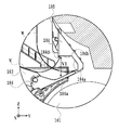
図5(a)は、スタッカ3が本体1から離れている状態の斜視図、図5(b)は、スタッカ3が本体1に接して定位置に位置決めされている状態の斜視図、図6(c)は、受容体40を省いた状態における図5(b)のVc矢視図である。ユーザーは、キャスター301を利用してスタッカ3を矢印Yの所定方向に移動させ、本体1の脚部2における正面側の面2aに対して、+Y方向を向く接触部材303の面303aを突き当てて係合させる。+X方向および−X方向を向く接触部材303,303の面303b,303b間の距離は、本体1の脚部2,2における内側面2b,2b間の距離L2より小さい。したがってスタッカ3は、本体1の脚部2,2の間においてX方向に沿って所定量移動可能である。このようなX方向の移動量を考慮し、排出口1aから排出されるシート端の基準位置X0側(図5(c)中の右側)のレッグ312は、その基準位置X0より内側(−X方向)に位置しないように、フットフレーム302の外側(X方向)にずれて配置されている。したがって、スタッカ3が図5(b)の状態において−X方向に移動しても、同図中の右側のレッグ312は、基準位置X0よりも内側(−X方向)に入ることはない。本例においては、非基準側(図5(c)中の左側)のレッグ312は、それに対応するフットフレーム302の外側(−X方向)に配置されている。しかし、この非基準側のレッグ312は、このような構成に限定されず、プリント装置10において使用されるシートの幅方向の外側に位置するように配置されればよい。 5A is a perspective view showing a state where the stacker 3 is separated from the main body 1, and FIG. 5B is a perspective view showing a state where the stacker 3 is in contact with the main body 1 and positioned at a fixed position. FIG. 5C is a view of the Vc arrow in FIG. 5B with the receptor 40 omitted. The user uses the casters 301 to move the stacker 3 in the predetermined direction of the arrow Y, and abuts the surface 303a of the contact member 303 facing the +Y direction against the front surface 2a of the leg portion 2 of the main body 1. To engage. The distance between the surfaces 303b and 303b of the contact members 303 and 303 facing the +X direction and the −X direction is smaller than the distance L2 between the inner side surfaces 2b and 2b of the legs 2 and 2 of the main body 1. Therefore, the stacker 3 can move between the legs 2 and 2 of the main body 1 along the X direction by a predetermined amount. Considering such a movement amount in the X direction, the leg 312 on the side of the reference position X0 (right side in FIG. 5C) of the sheet end discharged from the discharge port 1a is located inside (−X) of the reference position X0. The foot frame 302 is disposed outside (in the X direction) so as not to be located in the direction). Therefore, even if the stacker 3 moves in the −X direction in the state of FIG. 5B, the right leg 312 in the figure does not enter the inside (−X direction) of the reference position X 0 . In this example, the leg 312 on the non-reference side (the left side in FIG. 5C) is arranged outside (−X direction) of the corresponding foot frame 302. However, the leg 312 on the non-reference side is not limited to such a configuration, and may be arranged so as to be positioned outside in the width direction of the sheet used in the printing apparatus 10.

このように、レッグ312をシートの幅方向の外側に配置することにより、プリント装置10の下側の空間をシートの収容空間として有効利用することができる。したがって、プリント装置10の奥行き(図1(b)中の左右方向)を縮小しても大きいサイズのシートを収容することができる。また、プリント装置10の本体1とは別体のスタッカ3において、その下方部をシートの収容部として利用することにより、前述したようなフェイスダウン積載を実現することができる。 By arranging the legs 312 on the outer side in the width direction of the sheet in this manner, the space below the printing device 10 can be effectively used as a sheet accommodation space. Therefore, even if the depth of the printing device 10 (the left-right direction in FIG. 1B) is reduced, a large-sized sheet can be accommodated. Further, by using the lower portion of the stacker 3 separate from the main body 1 of the printing apparatus 10 as a sheet storage portion, face-down stacking as described above can be realized.

図6は、ガイドフラッパユニット180の要部の斜視図である。ガイドフラッパユニット180は、複数(本例の場合は、4つ)のフラッパ(可動ガイド)183と、それらのフラッパ183が回動可能に取り付けられる複数のガイド184と、複数のフラッパ183を保持するガイドロッド182と、を含む。ガイドロッド182の両端部には、ユーザーが直接触れることがないように、キャップ部材181が取り付けられている。ガイド184はガイドプレート400に取り付けられ、このガイドプレート400には、シートガイド185(可動ガイド)を回動可能に保持するシートガイドホルダ186も取り付けられている。シートガイド185は、不図示のねじりコイルバネにより、本体1側の方向(図7(b)中の矢印A方向)に付勢されている。ガイド184とシートガイドホルダ186は、ガイドプレート400を介してバックステイ321上に取り付けられる。 FIG. 6 is a perspective view of a main part of the guide flapper unit 180. The guide flapper unit 180 holds a plurality of (four in the present example) flappers (movable guides) 183, a plurality of guides 184 to which the flappers 183 are rotatably attached, and a plurality of flappers 183. And a guide rod 182. Cap members 181 are attached to both ends of the guide rod 182 so that the user does not directly touch them. The guide 184 is attached to the guide plate 400, and a sheet guide holder 186 that rotatably holds the sheet guide 185 (movable guide) is also attached to the guide plate 400. The sheet guide 185 is biased in the direction toward the main body 1 (the direction of arrow A in FIG. 7B) by a torsion coil spring (not shown). The guide 184 and the sheet guide holder 186 are mounted on the back stay 321 via the guide plate 400.

シートガイド185と接触部材303との関係について説明する。接触部材303は、前述したように、本体1とスタッカ3との位置決めを行うものである。しかし、このような接触部材303により位置決め箇所から離れた上方において、本体1とスタッカ3との間のシートのパスを接続しなければならず、そのパスの連結部(シートガイド185と本体1との接触部)には大きな部品公差が発生しやすい。本体1側の接触部は、シートの幅方向に延在する樹脂部品であるため、仮に、この接触部の位置において本体1とスタッカ3とを位置決めした場合には、その本体1側の接触部が破損するおそれがある。そのため、前述したように、接触部材303を用いて、本体1の強固な脚部2において本体1とスタッカ3とを位置決めする。仮に、ユーザーが強い力によって、スタッカ3を本体1に押し当てた場合でも、その荷重が本体1の強固な脚部2によって受けられるため破損は生じない。本例においては、パスの連結部における部品公差を吸収するために、ねじりコイルバネによって、シートガイド185を本体1側に付勢する。 The relationship between the sheet guide 185 and the contact member 303 will be described. The contact member 303 positions the main body 1 and the stacker 3 as described above. However, the sheet path between the main body 1 and the stacker 3 has to be connected above the position separated by the contact member 303, and the connecting portion of the path (the sheet guide 185 and the main body 1 is connected to each other). A large part tolerance is likely to occur in the contact part). Since the contact portion on the main body 1 side is a resin component that extends in the width direction of the sheet, if the main body 1 and the stacker 3 are positioned at the position of this contact portion, the contact portion on the main body 1 side. May be damaged. Therefore, as described above, the contact member 303 is used to position the main body 1 and the stacker 3 on the strong leg portion 2 of the main body 1. Even if the user presses the stacker 3 against the main body 1 with a strong force, the load is received by the strong leg portions 2 of the main body 1, so that no damage occurs. In this example, the seat guide 185 is biased toward the main body 1 side by a torsion coil spring in order to absorb the component tolerance in the connecting portion of the path.

図7(a)は、シートの収容部の上部に位置するフラッパ183およびシートガイド185と、本体1と、の位置関係を説明するためのプリント装置の側面図であり、説明に不要な部分の図示は省略している。図7(b)は、図7(a)のVIIb円部の拡大図である。 FIG. 7A is a side view of the printing apparatus for explaining the positional relationship between the flapper 183 and the sheet guide 185 located at the upper portion of the sheet storage portion and the main body 1. Illustration is omitted. FIG. 7B is an enlarged view of the VIIb circle portion of FIG. 7A.

フラッパ183は開閉操作され、開状態においては、本体1の排出口1aから排出されるシートを支持し、閉閉状態においては、そのシートを下方にガイドする。具体的に、フラッパ183が開いた状態とは、図7(b)中実線の回動位置にあって、ガイド184とシートガイドホルダ186とにより形成された横向きの凹部を開放し、かつ、排出口1aから排出されるシートの先端部分を支持可能な状態である。一方、フラッパ183が閉じた状態とは、図7(b)中2点鎖線の回動位置にあって、ガイド184とシートガイドホルダ186とにより形成された横向きの凹部を覆い、かつ排出口1aから排出されるシートの先端部分を支えずに下方にガイドする状態である。 The flapper 183 is operated to open and close, and supports the sheet discharged from the discharge port 1a of the main body 1 in the open state, and guides the sheet downward in the closed state. Specifically, the flapper 183 being open means that the flapper 183 is in the rotation position indicated by the solid line in FIG. 7B, the lateral recess formed by the guide 184 and the sheet guide holder 186 is opened, and the flapper 183 is discharged. The leading end portion of the sheet discharged from the outlet 1a can be supported. On the other hand, the state in which the flapper 183 is closed means that the flapper 183 is in the rotational position indicated by the chain double-dashed line in FIG. 7B, covers the lateral recess formed by the guide 184 and the sheet guide holder 186, and discharges the outlet 1a. In this state, the leading edge of the sheet discharged from the sheet is guided downward without being supported.

複数のフラッパ183のそれぞれが回動可能に取り付けられる複数のガイド184は、シートの幅方向に並んで配置されており、複数のフラッパ183は、それぞれ、図7(b)中の矢印U方向に開閉可能である。フラッパ183およびガイド184は、後述するように、シートを下方にガイドするガイド部としての機能、およびシートを支持する受け部としての機能をもつ。 The plurality of guides 184 to which each of the plurality of flappers 183 is rotatably attached are arranged side by side in the width direction of the sheet, and the plurality of flappers 183 are respectively arranged in the arrow U direction in FIG. 7B. It can be opened and closed. The flapper 183 and the guide 184 have a function as a guide portion for guiding the sheet downward and a function as a receiving portion for supporting the sheet, as described later.

図7(b)中の実線のようにフラッパ183が開いた状態(後述する第1および第2受容形態)においては、複数のシートガイド185のそれぞれの先端が本体1に接触する。その理由は、それぞれのシートガイド185が不図示のねじりコイルバネにより矢印A方向に付勢されていて、それぞれのシートガイド185が独立して本体1に接触するからである。これにより、シートガイド185は、排出口1aから排出されるシートの先端を本体1側からガイド184側へ受け渡すためのガイドとして機能する。シートガイド185の先端が接触する本体1の部分には、シートをガイドする排出ガイドが形成されている。一方、図8(b)中の2点鎖線のようにフラッパ183が閉じた状態においては、フラッパ183の先端部183aが本体1に接触する。この状態のフラッパ183は、排出口1aから排出されるシートの先端を本体1側からガイド184側へ受け渡すためのガイドとして機能する。 In the state where the flapper 183 is open as shown by the solid line in FIG. 7B (first and second receiving modes described later), the respective tip ends of the plurality of sheet guides 185 contact the main body 1. The reason is that each sheet guide 185 is biased in the direction of arrow A by a torsion coil spring (not shown), and each sheet guide 185 independently contacts the main body 1. Accordingly, the sheet guide 185 functions as a guide for delivering the leading end of the sheet discharged from the discharge port 1a from the main body 1 side to the guide 184 side. A discharge guide for guiding the sheet is formed at the portion of the main body 1 with which the leading end of the sheet guide 185 contacts. On the other hand, in the state where the flapper 183 is closed as indicated by the chain double-dashed line in FIG. 8B, the tip end 183 a of the flapper 183 contacts the main body 1. The flapper 183 in this state functions as a guide for transferring the leading edge of the sheet discharged from the discharge port 1a from the main body 1 side to the guide 184 side.

複数のフラッパ183のそれぞれの先端部183aを本体1に確実に接触させるために、フラッパ183は、図8(c),(d)のようにガイドロッド182に取り付けられている。すなわち、フラッパ183とガイドロッド182との間に隙間Tを形成して、フラッパ183にガタを持たせるように、段状のビス187などを用いてフラッパ183をガイドロッド182に取り付ける。このようにフラッパ183にガタを持たせることにより、それぞれのフラッパ183が閉じた状態において、それらの先端部183aは本体1に倣うように個別に変位する。この結果、それぞれのフラッパ183の先端部183aは本体に確実に接触して、それらの先端部183aと本体1との間へのシートの先端の入り込みが防止される。フラッパ183の先端部183aが接触する本体1の部分には、シートをガイドする排出ガイドが形成されている。 The flappers 183 are attached to the guide rod 182 as shown in FIGS. 8C and 8D in order to surely bring the respective tip portions 183a of the plurality of flappers 183 into contact with the main body 1. That is, the flapper 183 is attached to the guide rod 182 by using a stepped screw 187 or the like so that a gap T is formed between the flapper 183 and the guide rod 182 and the flapper 183 has a play. By providing the flapper 183 with backlash in this manner, the tip portions 183a of the flappers 183 are individually displaced so as to follow the main body 1 when the flappers 183 are closed. As a result, the front end portions 183a of the flappers 183 surely contact the main body, and the front end of the sheet is prevented from entering between the front end portions 183a and the main body 1. A discharge guide for guiding the sheet is formed at the portion of the main body 1 with which the tip end portion 183a of the flapper 183 contacts.

図8(a)は、後述する第3受容形態におけるフラッパ183の状態の説明図であり、ガイドロッド182が左右のアッパーロッドベース322上に位置することにより、フラッパ183が開いた状態に維持される。このような開いた状態のフラッパ183上に多数のシートが積載された場合、それぞれのフラッパ183がガイドロッド182に対してガタを持っているため、複数のフラッパ183の先端部183aは、アッパーロッド121上に倣うように位置する。したがって、それぞれの先端部183aに掛かるシートの重さをアッパーロッド121によって受けることができる。その結果、後述する第3受容形態におけるフラッパ183の耐荷重性を確保し、その破損を防止することができる。 FIG. 8A is an explanatory diagram of a state of the flapper 183 in the third receiving configuration described later, and the guide rod 182 is positioned on the left and right upper rod bases 322, so that the flapper 183 is maintained in the open state. It When a large number of sheets are stacked on the flapper 183 in the open state as described above, each flapper 183 has a backlash with respect to the guide rod 182. Therefore, the tip end portions 183a of the plurality of flappers 183 have upper rods 183a. It is located so as to follow 121. Therefore, the weight of the sheet hanging on each tip portion 183a can be received by the upper rod 121. As a result, the load bearing capacity of the flapper 183 in the third receiving mode described later can be secured and its damage can be prevented.

図8(b)は、後述する第4受容形態におけるフラッパ183の状態の説明図であり、ガイドロッド182が左右のアッパーロッドベース322上に位置することにより、フラッパ183が開いた状態に維持される。第4受容形態においては、アッパーロッド121が左右のアッパーロッドベース322上から外される。それぞれのフラッパ183がガイドロッド182に対してガタを持っているため、それらのフラッパ183は、ガイドロッド182の動きを規制しない。したがってガイドロッド182は、傾くことなく、その両端部がアッパーロッドベース322の平面部322b上に位置する。複数のフラッパ183は、その自重により、ガイドロッド182に対するガタ付きの分だけガイドロッド182からぶら下がった状態となる。ガイドロッド182は、図7(d)のようにフラッパ183の平面部183bから突出するため、シートの幅方向において一様に連続するガイドロッド182によって、排出口1aから排出されるシートを確実に受けることができる。この結果、フラッパ183の相互間からのシートの落ち込みを防止することができる。また、図6および図7(c)のように、フラッパ183の両面に突起形状(リブ)183dを形成することにより、フラッパ183とシートとの摩擦抵抗を低減させることができ、さらにフラッパ183の軽量化を図ることができる。フラッパ183の軽量化により、ユーザーはより小さな操作力によってフラッパ183を回動させることができる。 FIG.8(b) is explanatory drawing of the state of the flapper 183 in the 4th receiving form mentioned later, and when the guide rod 182 is located on the left and right upper rod bases 322, the flapper 183 is maintained in the open state. It In the fourth receiving configuration, the upper rod 121 is removed from the left and right upper rod bases 322. Since each flapper 183 has a play with respect to the guide rod 182, those flappers 183 do not regulate the movement of the guide rod 182. Therefore, the guide rod 182 does not incline and both ends thereof are positioned on the flat surface portion 322b of the upper rod base 322. Due to the weight of the flappers 183, the flappers 183 hang down from the guide rod 182 by an amount corresponding to the play of the guide rod 182. Since the guide rod 182 projects from the flat surface portion 183b of the flapper 183 as shown in FIG. 7D, the guide rod 182 that is uniformly continuous in the width direction of the sheet ensures that the sheet discharged from the discharge port 1a is discharged. Can receive. As a result, it is possible to prevent the sheets from falling between the flappers 183. Further, as shown in FIGS. 6 and 7C, by forming protrusions (ribs) 183d on both sides of the flapper 183, the frictional resistance between the flapper 183 and the sheet can be reduced. The weight can be reduced. The lighter weight of the flapper 183 allows the user to rotate the flapper 183 with a smaller operating force.

フラッパ183の回動中心189は、フラッパ183の重力方向の下側に設定されている。また、回動中心189は、上側のロール紙保持部160に保持されるロール紙の回転中心よりも下方に位置し、かつ、下側のロール紙保持部161に保持されるロール紙の回転中心よりも上方に位置する。したがってプリント装置10においては、重力方向に、排出口1a、ロール紙保持部160におけるロール紙の回転中心、フラッパ183の回動中心189、ロール紙保持部161におけるロール紙の回転中心の順に位置する。また、図7(b)中の2点鎖線のように、フラッパ183が閉じた状態においては、フラッパ183の先端部183aが回動中心189よりも本体1に近い側(図7(b)中の右側)に位置する。そのため、フラッパ183の先端部183aは、フラッパ183とガイドロッド182との自重によって寄り掛かるように本体1に接触する。その結果、付勢力を付与するためのバネ等の部品を必要とすることなく、フラッパ183の先端部183aを本体1に接触させることができる。 The rotation center 189 of the flapper 183 is set below the flapper 183 in the gravity direction. The rotation center 189 is located below the rotation center of the roll paper held by the upper roll paper holder 160, and the rotation center of the roll paper held by the lower roll paper holder 161. It is located above. Therefore, in the printing apparatus 10, the discharge port 1a, the center of rotation of the roll paper in the roll paper holder 160, the center of rotation 189 of the flapper 183, and the center of rotation of the roll paper in the roll paper holder 161 are located in this order in the direction of gravity. .. Further, as shown by the chain double-dashed line in FIG. 7B, when the flapper 183 is closed, the tip end 183a of the flapper 183 is closer to the main body 1 than the rotation center 189 (in FIG. 7B). Located on the right side of). Therefore, the tip end portion 183 a of the flapper 183 contacts the main body 1 so as to lean against the dead weight of the flapper 183 and the guide rod 182. As a result, the tip portion 183a of the flapper 183 can be brought into contact with the main body 1 without requiring a component such as a spring for applying a biasing force.

図9は、本体1にスタッカ3を接近させたときのフラッパ183の動作の説明図である。図9(a)は、図7(a)のIXa−IXa線に沿う断面図であり、説明に不要な部分の図示は省略している。図9(b)は、図9(a)のIXb円部の拡大図である。 FIG. 9 is an explanatory diagram of the operation of the flapper 183 when the stacker 3 approaches the main body 1. FIG. 9A is a cross-sectional view taken along the line IXa-IXa in FIG. 7A, and the illustration of parts unnecessary for the description is omitted. FIG. 9B is an enlarged view of the IXb circle portion of FIG. 9A.

図9(a)において、シートの基準位置側のフラッパ183におけるシートの幅方向の中央位置をXhとし、非基準側のフラッパ183におけるシートの幅方向の中央位置Xaとして、それらの位置Xh,Xaの間の距離をLfとする。プリンタ1に対してスタッカ3をY方向から接触させる際に、以下の状況を想定する。まず、接触部材303の面303aを本体1の脚部2の正面側の面2aに突き当てた状態において、フラッパ先端部183aが接触する本体1の設計上の位置をDpとする。位置Dpと基準位置側のフラッパ183の中央位置Xhとの交点をDhとし、この交点Dhを中心として、公差または歪み等の影響により、フラッパ183の先端部183aと接触する本体1の位置が角度α傾いた場合を想定する。この場合、非基準位置側のフラッパ183の中央位置XaにおけるマイナスY方向の変位量Ypは、Lf×tanαとなる。前述したように、複数のフラッパ183は、ガイドロッド182に対してガタを持っているため、ある程度の範囲において独立した回動が可能である。そのため、非基準位置側のフラッパ183は、基準位置側のフラッパ183に対してマイナスY方向にYsだけ変位可能である。この変位量Ysは、本体1側の変位量Ypよりも大きくなるように設定する。この変位量Ysは、フラッパ183の先端部183aの設計上の位置に対してマイナスY方向にずれる。しかし、それがマイナス方向にずれる場合も同様である。本例においては、マイナスY方向に15mm、プラスY方向に15mm程度の変位量を持つように設定されている。また、このようなガイドロッド182に対するフラッパ183のガタの設定条件は、フラッパ183を開いた状態とする後述の第3受容形態においても同様に適用できる。 In FIG. 9A, the center position in the width direction of the sheet in the flapper 183 on the reference position side of the sheet is Xh, and the center position Xa in the width direction of the sheet in the flapper 183 on the non-reference side is those positions Xh, Xa. The distance between them is Lf. The following situation is assumed when the stacker 3 is brought into contact with the printer 1 from the Y direction. First, in a state where the surface 303a of the contact member 303 is abutted against the front surface 2a of the leg portion 2 of the main body 1, the design position of the main body 1 with which the flapper tip 183a contacts is Dp. An intersection between the position Dp and the central position Xh of the flapper 183 on the reference position side is defined as Dh, and the position of the main body 1 in contact with the tip end 183a of the flapper 183 is an angle with the intersection Dh as a center due to the influence of tolerance or distortion. Assume a case of α inclination. In this case, the displacement amount Yp in the minus Y direction at the central position Xa of the flapper 183 on the non-reference position side is Lf×tan α. As described above, since the plurality of flappers 183 have a play with respect to the guide rod 182, they can rotate independently within a certain range. Therefore, the flapper 183 on the non-reference position side can be displaced by Ys in the negative Y direction with respect to the flapper 183 on the reference position side. The displacement amount Ys is set to be larger than the displacement amount Yp on the main body 1 side. This displacement amount Ys deviates in the negative Y direction from the designed position of the tip portion 183a of the flapper 183. However, the same applies when it shifts in the negative direction. In this example, the amount of displacement is set to about 15 mm in the minus Y direction and about 15 mm in the plus Y direction. Further, the play setting condition of the flapper 183 with respect to the guide rod 182 can be similarly applied to a third receiving mode described later in which the flapper 183 is opened.

図10は、図8のフラッパ183とガイドロッド182の他の構成例の説明図であり、図10(a)は、ガイドフラッパユニット180の斜視図、図10(b)は、図10(a)Xb円部の拡大図である。本例においては、ガイドロッドを複数の部材182a、182b、182c、182d、182eに分割されており、これらの部材によって複数のフラッパ183が連結されている。この構成においても、前述した構成と同様の効果が得られる。 FIG. 10 is an explanatory diagram of another configuration example of the flapper 183 and the guide rod 182 of FIG. 8, FIG. 10A is a perspective view of the guide flapper unit 180, and FIG. 10B is FIG. ) An enlarged view of the Xb circle portion. In this example, the guide rod is divided into a plurality of members 182a, 182b, 182c, 182d, 182e, and a plurality of flappers 183 are connected by these members. Also in this configuration, the same effect as the above-described configuration can be obtained.

図11は、ガイドフラッパユニット180の要部の拡大側面図であり、フラッパ183は開いた状態にある。ガイド184には、第1規制面184a、第2規制面184b、およびシートガイドホルダ186の第3規制面186aによって、シートの幅方向に延在する横向きの凹部(規制部)が形成されている。また、凹部の上面(第2規制面184b)における開口部近傍には、凸部184d(突起)が設けられている。第2規制面184bに対向する第3規制面186aは、図11中の左下方に傾斜する。凸部184dの先端と、その凸部184dの鉛直下方向の第3規制面186aの位置と、の間には、所定の隙間V1が形成される。隙間V1は、シートを最大数載置したときの厚さと、シート先端のカール量の最大値と、の合計より大きくなるように形成されている。シート先端のカール量は、シートを鉛直下方向に垂らした状態において、シートの最下面から、鉛直上方向に最大に反り返ったシート先端までの間の距離に対応する。 FIG. 11 is an enlarged side view of the main part of the guide flapper unit 180, and the flapper 183 is in an open state. The guide 184 is formed with a lateral recess (regulating portion) extending in the width direction of the sheet by the first regulating surface 184a, the second regulating surface 184b, and the third regulating surface 186a of the sheet guide holder 186. .. Further, a convex portion 184d (protrusion) is provided near the opening on the upper surface (second regulation surface 184b) of the concave portion. The third restriction surface 186a facing the second restriction surface 184b is inclined to the lower left in FIG. A predetermined gap V1 is formed between the tip of the protrusion 184d and the position of the third regulation surface 186a in the vertically downward direction of the protrusion 184d. The gap V1 is formed to be larger than the sum of the thickness when the maximum number of sheets are placed and the maximum value of the curl amount at the front end of the sheet. The curl amount of the sheet tip corresponds to the distance from the lowermost surface of the sheet to the sheet tip that is warped to the maximum in the vertically upward direction when the sheet is hung vertically downward.

本例においては、シート先端のカール量が大きく、かつ、一般的に多く使用される直径2インチ(50.8mm)の紙管に巻かれた普通紙を対象として場合に、その最大載置枚数を100枚に設定している。この普通紙の1枚の厚さは0.1mmであり、100枚載置した場合の厚さは10mm(=100×0.1)となる。また、シート先端のカール量の最大値(紙管に近い巻き始めの部分のシートの先端を鉛直下方向に垂らした状態において、そのシートの最下面から鉛直上方向に反り返ったシート先端までの距離)が10mmである。この場合、図11中の隙間V1は、20mm(=100×0.1+10mm)以上とする。また、凹部の奥行き方向(図11中の左右方向)における第2規制面184bの長さは、紙管の半径(25.4mm)より小さくする。凸部184dの垂直方向の高さ(すなわち、凹部の上面からの突出量)は、使用が想定されるシートの最大の厚さよりも大きくし、例えば、普通紙の紙厚0.1mmより大きくする。 In this example, when the amount of curl at the leading end of the sheet is large and the plain paper wound around a paper tube with a diameter of 2 inches (50.8 mm) that is commonly used is the target, the maximum number of sheets that can be placed Is set to 100 sheets. The thickness of one sheet of plain paper is 0.1 mm, and the thickness when 100 sheets are placed is 10 mm (=100×0.1). Also, the maximum amount of curl at the tip of the sheet (the distance from the bottom surface of the sheet to the tip of the sheet that warps vertically upward when the tip of the sheet at the beginning of winding near the paper core is hung vertically downward) ) Is 10 mm. In this case, the gap V1 in FIG. 11 is set to 20 mm (=100×0.1+10 mm) or more. Further, the length of the second restricting surface 184b in the depth direction of the recess (the left-right direction in FIG. 11) is smaller than the radius (25.4 mm) of the paper tube. The height of the convex portion 184d in the vertical direction (that is, the amount of protrusion from the upper surface of the concave portion) is set to be larger than the maximum thickness of the sheet assumed to be used, for example, larger than the paper thickness of 0.1 mm of plain paper. ..

アッパーロッドユニット350およびガイドフラッパユニット180の形態を変更して、それらの形態を組み合わせることにより、柔軟性のある受容体40の使用形態が変更可能である。すなわち、ユーザーは、本体1の排出口1aから排出されるシートを受容するときのスタッカ3の受容形態を選択して、プリント形態の多様化に対応することができる。以下、スタッカ3の受容形態について説明する。 By changing the forms of the upper rod unit 350 and the guide flapper unit 180 and combining these forms, the usage form of the flexible receiver 40 can be changed. That is, the user can select the receiving mode of the stacker 3 when receiving the sheet discharged from the discharge port 1a of the main body 1 to cope with the diversification of the printing mode. Hereinafter, the receiving form of the stacker 3 will be described.

(第1受容形態)
図12は、第1受容形態が選択されたときのプリント装置の説明図である。図12(a)は、そのプリント装置の斜視図、図12(b)は、そのプリント装置の側面図、図12(c)は、受容体40の図示を省略したプリント装置の正面図である。
(First receiving form)
FIG. 12 is an explanatory diagram of the printing apparatus when the first receiving mode is selected. 12A is a perspective view of the printing apparatus, FIG. 12B is a side view of the printing apparatus, and FIG. 12C is a front view of the printing apparatus in which the receiver 40 is omitted. ..

第1受容形態において、アッパーロッドユニット350のアッパーロッド121は、左右のアッパーロッドベース322上に位置決めされている。柔軟性の受容体40は、図12(b)のように、アッパーロッドユニット350、フロントロッドユニット330、およびリアロッドユニット340によって「への字状」に保持され、これによりシートの収容部を形成する。バックステイ321に取り付けられたロールガイドユニット370の第1のロールガイド371と、受容体40と、の間に隙間V2が形成される。本体1には、ロール紙162からシートを分離して供給するための供給手段500が、ロール紙162の幅方向にずれた位置に複数配置されており、ロールガイドユニット370は、図12(c)のように、供給手段500と干渉しない位置に取り付けられている。ガイドフラッパユニット180のフラッパ183は、本体1の排出口1aから排出されるシートを下方にガイドする位置、つまり、そのシートの先端を第1のロールガイド371と受容体40との間の隙間V2に導く位置に回動されている。 In the first receiving configuration, the upper rod 121 of the upper rod unit 350 is positioned on the left and right upper rod bases 322. As shown in FIG. 12(b), the flexible receiver 40 is held in a "V-shape" by the upper rod unit 350, the front rod unit 330, and the rear rod unit 340, and thereby the seat receiving portion is held. Form. A gap V2 is formed between the first roll guide 371 of the roll guide unit 370 attached to the back stay 321 and the receiver 40. In the main body 1, a plurality of supply means 500 for separating and supplying a sheet from the roll paper 162 are arranged at positions displaced in the width direction of the roll paper 162, and the roll guide unit 370 is shown in FIG. ), it is attached at a position where it does not interfere with the supply means 500. The flapper 183 of the guide flapper unit 180 guides the sheet discharged from the discharge port 1a of the main body 1 downward, that is, the tip of the sheet is a gap V2 between the first roll guide 371 and the receiver 40. It has been rotated to a position leading to.

本体1の排出口1aから排出されるシートW1は、排出口ガイド1b、フラッパ183、第1のロールガイド371、および第2のロールガイド372によって下方にガイドされ、その先端W1aは、第1のシート突き当て部材170に突き当てられて止まる。その後、シートW1が排出され続けられることにより、そのシートW1の中間部は、アッパーロッドユニット350のアッパーロッド121の位置を変曲点として、図12(b)のように、本体1から離れる側に湾曲するループを形成する。その後、シートW1の後端W1bがカットされることにより、シートW1は、アッパーロッド121の位置を変曲点として図12(b)中の左方に反転する。その後、端W1bは、先に排出されたシートW2の後端W2bと同様に、フロントロッドユニット330のトップロッド20から下方に垂れ下がる。シートW1,W2は、図12(b)のように、それらの先端W1a,W2aと中間部との間の部分が受容体40内に位置し、それらの中間部と後端W1b,W2bとの間の部分が受容体40上に支持されるように収容される。 The sheet W1 discharged from the discharge port 1a of the main body 1 is guided downward by the discharge port guide 1b, the flapper 183, the first roll guide 371, and the second roll guide 372, and the leading end W1a thereof is The sheet abutment member 170 abuts and stops. Thereafter, as the sheet W1 is continuously discharged, the intermediate portion of the sheet W1 is separated from the main body 1 as shown in FIG. 12B with the position of the upper rod 121 of the upper rod unit 350 as an inflection point. To form a curved loop. Then, by cutting the rear end W1b of the sheet W1, the sheet W1 is inverted to the left in FIG. 12B with the position of the upper rod 121 as an inflection point. After that, the end W1b hangs downward from the top rod 20 of the front rod unit 330, similarly to the rear end W2b of the previously discharged sheet W2. In the sheets W1 and W2, as shown in FIG. 12B, the portions between the leading ends W1a and W2a and the intermediate portions are located inside the receiver 40, and the intermediate portions and the rear ends W1b and W2b are formed. The part in between is accommodated so as to be supported on the receiver 40.

この第1受容形態は、比較的大きなサイズのシート(例えば、A0縦)に適した形態であり、シートのプリント面を下にしたフェイスダウン積載が可能である。 This first receiving form is suitable for a relatively large size sheet (for example, A0 length), and face-down stacking with the print side of the sheet facing down is possible.

(第2受容形態)
図13は、第2受容形態が選択されたときのプリント装置の説明図である。図13(a)は、そのプリント装置の斜視図、図13(b)は、そのプリント装置の側面図、図13(c)は、受容体40の図示を省略したプリント装置の正面図である。前述した第1の収容形態のスタッカ3に対して、ユーザーが第2のシートストッパユニット380を装着することによって第2収容形態となる。シートストッパユニット380のワイヤートレイ382は、第1のシート突き当て部材170と同様に、シートの先端を止めるように機能する。
(Second accepting form)
FIG. 13 is an explanatory diagram of the printing apparatus when the second receiving mode is selected. 13A is a perspective view of the printing apparatus, FIG. 13B is a side view of the printing apparatus, and FIG. 13C is a front view of the printing apparatus in which the receiver 40 is omitted. .. When the user mounts the second sheet stopper unit 380 on the stacker 3 in the first storage mode described above, the second storage mode is achieved. The wire tray 382 of the sheet stopper unit 380 functions to stop the leading edge of the sheet, similarly to the first sheet abutting member 170.

第2収容形態において、排出口1aから排出されるシートW3は、排出口ガイド1b、フラッパ183、およびロールガイドユニット370によって下方にガイドされる。そのシートW3の先端W3aは、第2のシートストッパユニット380のワイヤートレイ382に突き当てられて止まる。この第2のシートストッパユニット380は、図13(c)のように、シートW3(1)の幅WAの中心XCよりもシート端の基準位置X0寄りに所定量Sだけずれた位置に装着されている。例えば、シートW3がA0サイズである場合、所定量Sは20mmである。シートW3は、先端W3aがシートW3(1)のようにワイヤートレイ382によって止められた後、さらに排出が進行することにより、シートW3(2)のように、アッパーロッド121の位置を変曲点として、本体1から離れる側に湾曲するループを形成する。その後、シートW3の後端W3bがカットされることにより、そのシートW3は、シートW3(3),W3(4)のように、アッパーロッド121の位置を変曲点として図13(b)中の左方に反転する。シートW3は、図13(b)のように、その先端W3aと中間部との間の部分が受容体40内に位置し、その中間部と後端W3bとの間の部分が受容体40上に支持されるように収容される。このようなシートW3は、連続的に排出されることにより順次積載される。 In the second accommodation mode, the sheet W3 discharged from the discharge port 1a is guided downward by the discharge port guide 1b, the flapper 183, and the roll guide unit 370. The leading edge W3a of the sheet W3 is abutted against the wire tray 382 of the second sheet stopper unit 380 and stopped. As shown in FIG. 13C, the second sheet stopper unit 380 is mounted at a position displaced from the center XC of the width WA of the sheet W3(1) by a predetermined amount S toward the reference position X0 of the sheet end. ing. For example, when the sheet W3 has an A0 size, the predetermined amount S is 20 mm. Like the sheet W3(2), the sheet W3 has its leading end W3a stopped by the wire tray 382 like the sheet W3(1). As, a loop that curves toward the side away from the main body 1 is formed. Then, the rear end W3b of the sheet W3 is cut, so that the sheet W3 has a position where the upper rod 121 is an inflection point, as in the sheets W3(3) and W3(4). Flip to the left of. As shown in FIG. 13B, the sheet W3 has a portion between the front end W3a and the intermediate portion located inside the receiver 40, and a portion between the intermediate portion and the rear end W3b on the receiver 40. It is housed so as to be supported by. Such sheets W3 are sequentially discharged and sequentially stacked.

カッター6(図1(b)参照)が基準位置X0側からシートW3をカットするときに、シートW3が基準位置X0側から斜めに落下して、シートW3が斜めにカットされるおそれがある。しかし、シートW3の中心XCよりも基準位置X0寄りにずれた位置において、第2のシートストッパユニット38がシートW3の先端W3aを支えるため、シートW3の斜めの落下を抑制して、シートW3を正確にカットすることができる。 When the cutter 6 (see FIG. 1B) cuts the sheet W3 from the reference position X0 side, the sheet W3 may fall obliquely from the reference position X0 side and the sheet W3 may be cut obliquely. However, since the second sheet stopper unit 38 supports the leading end W3a of the sheet W3 at a position displaced from the center XC of the sheet W3 closer to the reference position X0, the sheet W3 is prevented from being obliquely dropped, and the sheet W3 is removed. Can be cut accurately.

第2受容形態は、前述した第1受容形態において収容されるシートよりも小さいサイズのシート(例えば、A1縦)に適した形態であり、シートのプリント面を下にしたフェイスダウン積載が可能である。 The second receiving form is a form suitable for a smaller size sheet (for example, A1 vertical size) than the sheets accommodated in the above-described first receiving form, and is capable of face-down stacking with the printed surface of the sheet facing down. is there.

(第3受容形態)
図14は、第3受容形態が選択されたときのプリント装置の説明図である。図14(a)は、そのプリント装置の斜視図、図14(b)は、そのプリント装置の側面図、図14(c)は、図14(b)のXIVc円部の拡大図である。前述した第1の収容形態のスタッカ3において、フラッパ183は、排出口1aから排出されるシートを下方にガイドする位置に回動されている。第2の収容形態は、そのフラッパ183がシートを支持する位置に回動されており、この点において第1の収容形態と異なる。
(Third accepting form)
FIG. 14 is an explanatory diagram of the printing apparatus when the third receiving mode is selected. 14A is a perspective view of the printing apparatus, FIG. 14B is a side view of the printing apparatus, and FIG. 14C is an enlarged view of the XIVc circle portion of FIG. 14B. In the stacker 3 of the above-described first storage mode, the flapper 183 is rotated to a position that guides the sheet discharged from the discharge port 1a downward. The second accommodation mode is different from the first accommodation mode in that the flapper 183 is rotated to a position for supporting the sheet.

フラッパ183がシートを支持する位置に回動されることにより、図12(b)中における第1のロールガイド371と受容体40との間に隙間V2、つまりシートを下方に導くパスが塞がれる。アッパーロッドユニットのアッパーロッド121には、図14(c)のように、受容体40を介してフラッパ183の先端部183aが当接する。フラッパ183の上面は、図14(c)中の左上方に傾斜し、アッパーロッド121とトップロッド20との間の受容体40は、図14(b)中の左下方に傾斜する。 By rotating the flapper 183 to the position for supporting the sheet, the gap V2, that is, the path for guiding the sheet downward is closed between the first roll guide 371 and the receiver 40 in FIG. 12B. Be done. As shown in FIG. 14C, the tip end portion 183 a of the flapper 183 contacts the upper rod 121 of the upper rod unit via the receiver 40. The upper surface of the flapper 183 is inclined to the upper left in FIG. 14(c), and the receiver 40 between the upper rod 121 and the top rod 20 is inclined to the lower left in FIG. 14(b).

第3受容形態において、排出口1aから排出されるプリント後のシートW4は、まず、シートW4(1)のように、排出口ガイド1bおよびシートガイド185によって下方にガイドされ、その先端W4(1)aがガイド184の凹部に突き当たって止められる。さらにシートW4の排出が進行することにより、シートW4(2)のように、トップロッド20の位置を変曲点として、本体1から離れる側に湾曲するループを形成する。その後、シートW4の後端W4bがカットされることにより、そのシートW4は、シートW4(3)のように、アッパーロッド121の位置を変曲点として図14(b)の左方に反転する。シートW4は、先端側の部分がフラッパ183の上面に支持され、その後端側の部分がアッパーロッド121とトップロッド20との間の受容体40上に支持される。シートW4(2),W4(3)の先端W4(2)a,W4(3)aは、図14(c)のように、ガイド184の凹部内に位置する。このようなシートW4は、連続的に排出されることにより順次積載される。 In the third receiving mode, the printed sheet W4 discharged from the discharge port 1a is first guided downward by the discharge port guide 1b and the sheet guide 185 like the sheet W4(1), and its leading end W4(1). ) A hits the concave portion of the guide 184 and is stopped. As the sheet W4 is further discharged, a loop that curves away from the main body 1 is formed with the position of the top rod 20 as the inflection point, as in the sheet W4(2). Thereafter, by cutting the rear end W4b of the sheet W4, the sheet W4 is inverted to the left in FIG. 14B with the position of the upper rod 121 as an inflection point like the sheet W4(3). .. The sheet W4 has a front end portion supported on the upper surface of the flapper 183, and a rear end portion supported on the receiver 40 between the upper rod 121 and the top rod 20. The leading ends W4(2)a and W4(3)a of the sheets W4(2) and W4(3) are located in the recesses of the guide 184 as shown in FIG. 14(c). Such sheets W4 are sequentially stacked by being continuously discharged.

第3の収容形態は、前述した第1および第2の受容形態における収容されるシートよりも小さいサイズのシート(例えば、A1横およびA2横)に適した形態であり、シートのプリント面を下にしたフェイスダウン積載が可能である。 The third storage form is a form suitable for a smaller size sheet (for example, A1 landscape and A2 landscape) than the sheets stored in the above-described first and second receiving forms, and the print surface of the sheet is placed downward. Face down loading is possible.

(第4受容形態)
図15は、第4受容形態が選択されたときのプリント装置の説明図である。図15(a)は、そのプリント装置の斜視図、図15(b)は、そのプリント装置の側面図であり、図15(a)においては、説明の便宜上、スタッカ3における同図中右側の構成部品の図示が省略されている。
(Fourth acceptance form)
FIG. 15 is an explanatory diagram of the printing apparatus when the fourth receiving mode is selected. FIG. 15A is a perspective view of the printing apparatus, and FIG. 15B is a side view of the printing apparatus. In FIG. 15A, the stacker 3 on the right side in FIG. Illustration of components is omitted.

アッパーロッド121は、第3の受容形態においては左右のアッパーロッドベース322上に位置決めされており、第4受容形態においてはロッドホルダー304上に移されている。この点において、第4受容形態は第3受容形態と異なる。柔軟性の受容体40は、その自重により下方に弛むように湾曲して、シート全体を受容可能な袋状となり、その最下点P2は、リアロッド30よりも下方に位置する。受容体40は、奥行き方向(図15(b)中の左右方向)において広い収容空間を形成する。フラッパ183は、第3の収容形態と同様にシートを支持する位置に回動されており、図15(b)の右側から左側に向かって斜め上方に突き出るように位置する。受容体40は、このようなフラッパ183の下方に位置する領域を含むようにシートの収容部を大きく形成する。 The upper rod 121 is positioned on the left and right upper rod bases 322 in the third receiving configuration, and is transferred to the rod holder 304 in the fourth receiving configuration. In this respect, the fourth receptor form is different from the third receptor form. The flexible receiver 40 is curved so as to slacken downward due to its own weight, forming a bag shape capable of receiving the entire sheet, and the lowest point P2 thereof is located below the rear rod 30. The receptor 40 forms a large accommodation space in the depth direction (the left-right direction in FIG. 15B). The flapper 183 is rotated to a position for supporting the sheet as in the third accommodation mode, and is positioned so as to project obliquely upward from the right side to the left side in FIG. 15B. The receiver 40 forms a large sheet storage portion so as to include a region located below the flapper 183.

第4受容形態においては、第3受容形態と同様に、排出口1aから排出されるシートW5は、シートW5(1)のように、排出口ガイド1bおよびシートガイド185によって下方にガイドされ、その先端がガイド184の凹部に突き当たって止められる。シートW5の先端側の部分は、ガイド184とフラッパ183上の領域Lpに支持される。さらにシートW5の排出が進行することにより、シートW5(2)のように、フラッパ183の先端部183a(図14(c)参照)の位置を変曲点として下方に向かうループを形成する。これにより、シートW5の後続部分は、受容体40などの他の部材に接触することなく収容空間内に垂れ下がる。その後、シートW5の後端がカットされることにより、シートW5(3)のように、開口領域Yから袋状の受容体40内に落下し、緩やかに畳まれた状態で収容される。 In the fourth receiving mode, similarly to the third receiving mode, the sheet W5 discharged from the discharge port 1a is guided downward by the discharge port guide 1b and the sheet guide 185 like the sheet W5(1), and The leading end hits the concave portion of the guide 184 and is stopped. The leading end side portion of the sheet W5 is supported by the guide 184 and the region Lp on the flapper 183. As the sheet W5 is further discharged, a downward loop is formed with the position of the tip end portion 183a (see FIG. 14C) of the flapper 183 as an inflection point, like the sheet W5(2). As a result, the subsequent portion of the sheet W5 hangs in the accommodation space without contacting other members such as the receiver 40. After that, the rear end of the sheet W5 is cut, so that the sheet W5(3) falls into the bag-shaped receiver 40 from the opening region Y and is accommodated in a gently folded state.

カットされる前のシートW5は、その先端側の部分がガイド184からフラッパ183上に及ぶ範囲に位置し、その後端側の部分が本体1によって保持されている。カット後のシートW5は、受容体40上に落下して収容されて載置される。カット前のシートW5の後端側の部分が本体1に保持されているため、シートW5の重心は、フラッパ183の先端部183aよりも本体1側(図15(b)中の右側)に位置する。そのためシートW5は、先端部183aを変曲点にして垂れ下がるループを形成した状態においても落下せず、その先端側の部分は、ガイド184からフラッパ183上に及ぶ範囲に位置する。シートW5がカットされて、その後端側の部分が本体1によって保持されなくなったときに、シートW5の重心は、フラッパ183の先端部183aよりも本体1から離れる側(図15(b)中に左側)に遷移する。そのため、カットされたシートW5は、自重により、ループ形状部分の中間付近から受容体40内に落下し、ループ形状を維持したまま緩やかに畳まれた状態で収容される。このようなシートW5は、連続的に排出されることにより順次積載される。 The sheet W<b>5 before being cut has its leading end portion located in a range extending from the guide 184 to the flapper 183, and its rear end portion held by the main body 1. The cut sheet W5 is dropped on the receiver 40, accommodated, and placed. Since the rear end portion of the sheet W5 before being cut is held by the main body 1, the center of gravity of the sheet W5 is positioned closer to the main body 1 side (right side in FIG. 15B) than the tip end portion 183a of the flapper 183. To do. Therefore, the sheet W5 does not drop even in the state where the loop that hangs down with the front end portion 183a as an inflection point is formed, and the front end side portion thereof is located in the range extending from the guide 184 to the flapper 183. When the sheet W5 is cut and the rear end portion is no longer held by the main body 1, the center of gravity of the sheet W5 has a center farther from the main body 1 than the tip end portion 183a of the flapper 183 (see FIG. 15(b)). Transition to the left side). Therefore, the cut sheet W5 falls into the receiver 40 from near the middle of the loop-shaped portion due to its own weight, and is accommodated in a gently folded state while maintaining the loop shape. Such sheets W5 are sequentially stacked by being continuously discharged.

このように第4収容形態においては、アッパーロッド121がロッドホルダー304上に移されることにより、受容体40は、フラッパ183の下方位置を含む領域に袋状の大きな収容部を形成する。シートW5は、フラッパ183の先端部183aから下垂するループ形状部分を他の部材に干渉されることなく形成でき、カットされることにより、そのループ形状を維持したまま落下して緩やかに折り畳まれる。したがって、連続的に収容されるシートW5は、緩やかに折り畳まれたままの状態で積載される。受容体40が低い位置においてシートW5を収容するため、シートW5の収容空間として、スタッカ3内の高さ方向の空間を有効に利用して、より多くのシートW5を収容することができる。また、シートW5のカールの度合いおよび長さに拘わらず、それを確実に収容することができる。 As described above, in the fourth accommodation mode, by moving the upper rod 121 onto the rod holder 304, the receiver 40 forms a large bag-shaped accommodation portion in the region including the position below the flapper 183. The sheet W5 can be formed by forming a loop-shaped portion that hangs down from the tip end portion 183a of the flapper 183 without being interfered by other members, and by being cut, the sheet W5 falls and is gently folded while maintaining the loop shape. Therefore, the continuously stored sheets W5 are stacked in a state of being gently folded. Since the receiver W accommodates the sheet W5 at a low position, it is possible to effectively use the space in the height direction inside the stacker 3 as the accommodation space for the sheet W5 and accommodate more sheets W5. Further, regardless of the degree of curl and the length of the sheet W5, it can be reliably accommodated.

この第4受容形態における収容対象のシートW5としては、主に、図面およびポスター等において多用されている普通紙およびコート紙のA0サイズおよびB0サイズなどの定型サイズのシートを想定している。しかし、これらの定型サイズのシートに限定さられず、また複数のサイズのシートを同時に収容することもできる。 As the sheet W5 to be accommodated in the fourth receiving mode, it is assumed that a regular size sheet such as A0 size and B0 size of plain paper and coated paper which is often used in drawings and posters is mainly used. However, the sheets are not limited to these standard size sheets, and sheets of a plurality of sizes can be accommodated at the same time.

第4受容形態において、受容体40の最下点P2は、先端部183aから下垂するシートW5のループ形状部分の下端P1よりも本体1側(図15(b)中の右側)に位置することが望ましい。あるいは、最下点P2を下端P1よりも本体1から離れる側(図15(b)中の左側)に位置させてもよい。いずれにしても、最下点P2と下端P1との位置関係によって、下端P1の下方位置における受容体40の内面が傾斜することが望ましい。このように形成された受容体40の傾斜面を利用することにより、ループ形状を維持したまま落下するシートは、そのループ形状が効率的に利用されて緩やかに折り畳まれる。 In the fourth receiving configuration, the lowest point P2 of the receiver 40 is located closer to the main body 1 side (right side in FIG. 15B) than the lower end P1 of the loop-shaped portion of the sheet W5 hanging from the leading end 183a. Is desirable. Alternatively, the lowest point P2 may be located on the side farther from the main body 1 than the lower end P1 (left side in FIG. 15B). In any case, it is desirable that the inner surface of the receptor 40 in the position below the lower end P1 be inclined depending on the positional relationship between the lowest point P2 and the lower end P1. By utilizing the inclined surface of the receptor 40 formed in this way, the sheet that falls while maintaining the loop shape is efficiently used for the loop shape and is gently folded.

(他の実施形態)
本発明は、プリント装置のみならず、シートに種々の処理を施すシート処理装置に対しても適用可能である。シートは、ロール状の巻回された形態のみに限定されず、予め所定の長さにカットされたシートであってもよく、また紙以外の材質のものであってもよい。
(Other embodiments)
The present invention can be applied not only to a printing apparatus but also to a sheet processing apparatus that performs various kinds of processing on a sheet. The sheet is not limited to the rolled form, and may be a sheet that is cut in advance to a predetermined length, or may be made of a material other than paper.

1 本体
3 スタッカ(シート収容装置)
10 プリント装置(プリンタ)
40 受容体(収容部)
183 フラッパ(可動ガイド)
185 シートガイド(可動ガイド)
312 レッグ(収容側支柱)
612 本体レッグ(本体側支柱)
613 本体フット(本体側足部)
620 フット(収容側足部)
303接触部材(位置決め部)
1 Main body 3 Stacker (sheet accommodating device)
10 Printing device (printer)
40 Receptor (container)
183 flapper (movable guide)
185 Seat guide (movable guide)
312 legs (support side)
612 Body leg (body side support)
613 Body foot (body side foot)
620 feet (foot on the accommodation side)
303 contact member (positioning part)

Claims (12)

本体側足部の上に備わる本体側支柱によって支えられるプリンタとは別体であり、前記
プリンタに対して使用位置に配置することができるシート収容装置であって、
前記プリンタの本体から排出されるシートの幅方向において、前記本体側足部よりもシートの中央の近くに位置する収容側足部と、
前記収容側足部の上に設けられて、前記幅方向において前記収容側足部よりも前記中央から離れて位置する収容側支柱と、
前記収容側支柱に支持されて、少なくとも前記本体の一部の下方位置を含む範囲にシー
トの収容空間を形成する収容部と、
を備えることを特徴とするシート収容装置。
A sheet accommodating device that is separate from a printer supported by a main body side column provided on a main body side foot portion and that can be arranged at a use position with respect to the printer,
In the width direction of the sheet discharged from the main body of the printer, the accommodation side foot portion located closer to the center of the sheet than the main body side foot portion,
An accommodation-side strut that is provided on the accommodation-side foot portion and is located farther from the center than the accommodation-side foot portion in the width direction,
An accommodating portion that is supported by the accommodating-side strut and that forms an accommodating space for the seat in a range including at least a lower position of a part of the main body,
A sheet accommodating device comprising:
前記幅方向における前記収容側支柱の中心は、前記幅方向における前記収容側足部の中心よりも、前記幅方向において前記中央から離れて位置することを特徴とする請求項1に記載のシート収容装置。 The sheet storage according to claim 1, wherein the center of the storage-side support column in the width direction is located farther from the center in the width direction than the center of the storage-side foot portion in the width direction. apparatus. 前記幅方向において前記中央寄りの前記収容側支柱の側面は、前記幅方向において前記中央寄りの前記収容側足部の側面よりも、前記幅方向において前記中央から離れて位置することを特徴とする請求項1に記載のシート収容装置。 The side surface of the accommodation-side strut closer to the center in the width direction is located farther from the center in the width direction than the side surface of the accommodation-side foot portion closer to the center in the width direction. The sheet storage device according to claim 1. 前記収容側支柱は、前記幅方向においてシートの端部の外側に位置し、
前記幅方向における前記収容空間の幅は、前記本体から排出されるシートの幅よりも大きいことを特徴とする請求項1から3のいずれか1項に記載のシート収容装置。
The accommodation side strut is located outside the end portion of the sheet in the width direction,
The sheet storage device according to claim 1, wherein a width of the storage space in the width direction is larger than a width of a sheet discharged from the main body.
前記収容側足部の位置と、前記本体から排出されるシートの前記幅方向の端部の位置と、は、前記幅方向において少なくとも一部が重なることを特徴とする請求項1から4のいずれか1項に記載のシート収容装置。 5. The position of the accommodation side foot portion and the position of the end portion in the width direction of the sheet discharged from the main body are at least partially overlapped in the width direction. The sheet storage device according to item 1. 前記シート収容装置は、所定方向から前記プリンタに接近して前記使用位置に移動し、 前記収容側足部は、前記本体側足部と係合することにより前記シート収容装置を前記使用位置に位置決めする位置決め部を備え、
前記位置決め部は、前記収容側支柱よりも前記所定方向の下流側に位置し、かつ前記幅方向において前記中央から離れる方向に突出するように前記収容側足部に設けられることを特徴とする請求項1から5のいずれか1項に記載のシート収容装置。
The sheet storage device moves to the use position by approaching the printer from a predetermined direction, and the storage side foot portion positions the sheet storage device in the use position by engaging with the main body side foot portion. Equipped with a positioning unit
The said positioning part is provided in the said accommodation side leg part so that it may be located in the downstream of the said accommodation side pillar in the said predetermined direction, and may protrude in the direction away from the said center in the said width direction. Item 6. The sheet accommodation device according to any one of items 1 to 5.
前記プリンタは、前記本体側足部と前記本体側支柱とを左右に2組備え、
前記シート収容装置は、前記収容側足部と前記収容側支柱とを左右2組備え、
前記左右の収容側足部の少なくとも一方は、それに対応する前記本体側足部よりも前記幅方向において前記中央の近くに位置し、
前記左右の収容側支柱の少なくとも一方は、それに対応する前記本体側足部よりも前記幅方向において前記中央から離れて位置し、
前記収容部は、前記左右の収容側支柱に支持されることを特徴とする請求項1から6のいずれか1項に記載のシート収容装置。
The printer includes two pairs of left and right body-side feet and body-side columns.
The sheet storage device includes two pairs of left and right storage-side legs and storage-side columns.
At least one of the left and right accommodation side foot portions is located closer to the center in the width direction than the corresponding body side foot portion,
At least one of the left and right housing-side columns is located farther from the center in the width direction than the corresponding body-side foot portion,
The sheet storage device according to claim 1, wherein the storage portion is supported by the left and right storage-side columns.
前記シート収容装置は、前記収容部の上部に、前記本体から排出されるシートをガイドする移動可能な可動ガイドを備え、
前記可動ガイドは、前記シート収容装置が前記使用位置に移動したときに前記本体に接することを特徴とする請求項1から7のいずれか1項に記載のシート収容装置。
The sheet storage device includes a movable movable guide for guiding a sheet discharged from the main body, in the upper portion of the storage portion.
8. The sheet storage device according to claim 1, wherein the movable guide contacts the main body when the sheet storage device moves to the use position.
前記可動ガイドは、前記幅方向に複数配置されていることを特徴とする請求項8に記載のシート収容装置。 The sheet storage device according to claim 8, wherein a plurality of the movable guides are arranged in the width direction. 前記収容部は、収容側支柱に支持される第1ロッドと、前記本体の下方位置に位置する第2ロッドと、前記第1ロッドと前記第2ロッドにより保持されるシート状の受容体と、により前記収容空間を形成することを特徴とする請求項1から9のいずれか1項に記載のシート収容装置。 The housing portion includes a first rod supported by a housing-side strut, a second rod positioned below the main body, a sheet-shaped receiving body held by the first rod and the second rod, The sheet accommodation device according to any one of claims 1 to 9, wherein the accommodation space is formed by. 本体側足部の上に備わる本体側支柱によって支えられ、シートをプリントして排出するプリンタの本体と、
請求項1から10のいずれか1項に記載のシート収容装置と、
を備えることを特徴とするプリント装置。
The main body of the printer, which is supported by the main body side support provided on the main body side foot part, prints and discharges the sheet,
A sheet storage device according to any one of claims 1 to 10,
A printing apparatus comprising:
前記本体は、シートが巻回されたロールを支持するロール支持部と、前記ロールから引き出されたシートにプリントするプリント部と、前記プリント部におけるシートの幅方向の側部を支える側部支持体と、を備え、
前記本体側支柱は、前記側部支持体の直下に位置して前記側部支持体を支えることを特徴とする請求項11に記載のプリント装置。
The main body includes a roll support portion that supports a roll around which the sheet is wound, a print portion that prints on the sheet pulled out from the roll, and a side support that supports a side portion of the print portion in the width direction of the sheet. And
The printing apparatus according to claim 11, wherein the main body side support is located immediately below the side support and supports the side support.
JP2017095406A 2017-05-12 2017-05-12 Sheet storage device and printing device Active JP6708584B2 (en)

Priority Applications (3)

Application Number Priority Date Filing Date Title
JP2017095406A JP6708584B2 (en) 2017-05-12 2017-05-12 Sheet storage device and printing device
US15/970,190 US10754286B2 (en) 2017-05-12 2018-05-03 Printing apparatus, sheet housing apparatus, and printer
US16/929,724 US11003123B2 (en) 2017-05-12 2020-07-15 Printing apparatus, sheet housing apparatus, and printer

Applications Claiming Priority (1)

Application Number Priority Date Filing Date Title
JP2017095406A JP6708584B2 (en) 2017-05-12 2017-05-12 Sheet storage device and printing device

Publications (3)

Publication Number Publication Date
JP2018192627A JP2018192627A (en) 2018-12-06
JP2018192627A5 JP2018192627A5 (en) 2019-05-09
JP6708584B2 true JP6708584B2 (en) 2020-06-10

Family

ID=64096873

Family Applications (1)

Application Number Title Priority Date Filing Date
JP2017095406A Active JP6708584B2 (en) 2017-05-12 2017-05-12 Sheet storage device and printing device

Country Status (2)

Country Link
US (2) US10754286B2 (en)
JP (1) JP6708584B2 (en)

Families Citing this family (2)

* Cited by examiner, † Cited by third party
Publication number Priority date Publication date Assignee Title
JP6708584B2 (en) 2017-05-12 2020-06-10 キヤノン株式会社 Sheet storage device and printing device
DE102017123937A1 (en) * 2017-10-13 2019-04-18 di support GmbH Printing system for printing images and / or documents

Family Cites Families (14)

* Cited by examiner, † Cited by third party
Publication number Priority date Publication date Assignee Title
US5040777A (en) * 1989-10-23 1991-08-20 Xerox Corporation Foot pedal operated, modular, roll up paper feeder apparatus
US5238316A (en) * 1992-02-20 1993-08-24 Balt, Inc. Printer paper collection structure
JP2008094565A (en) * 2006-10-12 2008-04-24 Canon Inc Sheet storage mechanism and recorder
JP5147525B2 (en) * 2008-05-08 2013-02-20 桂川電機株式会社 Stacker
CN102897573B (en) * 2012-11-16 2016-03-02 上海德拉根印刷机械有限公司 Automatically paper collecting machine do not shut down by roller type sheet-fed
US8911199B2 (en) * 2013-02-28 2014-12-16 Xerox Corporation Cart with a support surface having a selectively adjustable contour and a printing system sheet stacker incorporating the cart
JP2015189559A (en) * 2014-03-28 2015-11-02 セイコーエプソン株式会社 recording device
US9457978B2 (en) * 2014-09-30 2016-10-04 Canon Kabushiki Kaisha Article delivery system
JP2016069156A (en) * 2014-09-30 2016-05-09 キヤノン株式会社 Article delivery system
JP6422285B2 (en) * 2014-09-30 2018-11-14 キヤノン株式会社 Printer and stacker
JP6440603B2 (en) 2015-09-29 2018-12-19 キヤノン株式会社 Article receiving device
EP3150530B1 (en) 2015-09-29 2020-01-08 Canon Kabushiki Kaisha Reception apparatus
JP6618312B2 (en) * 2015-09-29 2019-12-11 キヤノン株式会社 Printing device
JP6708584B2 (en) 2017-05-12 2020-06-10 キヤノン株式会社 Sheet storage device and printing device

Also Published As

Publication number Publication date
JP2018192627A (en) 2018-12-06
US11003123B2 (en) 2021-05-11
US20180329350A1 (en) 2018-11-15
US20200348619A1 (en) 2020-11-05
US10754286B2 (en) 2020-08-25

Similar Documents

Publication Publication Date Title
JP6273430B2 (en) Recording device
US20210403268A1 (en) Sheet storage device and printing apparatus
CN108501549B (en) Printing apparatus and sheet accommodating device
JP6708584B2 (en) Sheet storage device and printing device
US20050280202A1 (en) Printer having media bin and method for operation
JP2005162461A (en) Discharged paper storing device
JP6711780B2 (en) Recording device
JP6971625B2 (en) Sheet accommodating device and printing device
US10457516B2 (en) Sheet storage apparatus and printing apparatus
JP2008094575A (en) Sheet storage mechanism and recorder
JP2003095512A (en) Paper discharging stacker and recording apparatus having the same
JP2010070287A (en) Paper sheet stacking device and recording device
JP6882058B2 (en) Sheet storage device and printing device
JP6562060B2 (en) Recording apparatus and ejection method in recording apparatus
JP2022147361A (en) Discharge device
JP6821468B2 (en) Printing device
JP2020083518A (en) Recording apparatus
JP7114673B2 (en) Sheet storage device and printing device
JP2022020505A (en) Image recording device
EP3960670B1 (en) Supply device for roll medium and recording device
JPH09286557A (en) Sheet storing device
US20190263610A1 (en) Recording apparatus
JPH08244996A (en) Image forming device
JPH01192639A (en) Paper feeding device
JP2023093897A (en) Medium mounting device

Legal Events

Date Code Title Description
A521 Written amendment

Free format text: JAPANESE INTERMEDIATE CODE: A523

Effective date: 20190327

A621 Written request for application examination

Free format text: JAPANESE INTERMEDIATE CODE: A621

Effective date: 20190327

A977 Report on retrieval

Free format text: JAPANESE INTERMEDIATE CODE: A971007

Effective date: 20200129

A131 Notification of reasons for refusal

Free format text: JAPANESE INTERMEDIATE CODE: A131

Effective date: 20200218

A521 Written amendment

Free format text: JAPANESE INTERMEDIATE CODE: A523

Effective date: 20200403

TRDD Decision of grant or rejection written
A01 Written decision to grant a patent or to grant a registration (utility model)

Free format text: JAPANESE INTERMEDIATE CODE: A01

Effective date: 20200421

A61 First payment of annual fees (during grant procedure)

Free format text: JAPANESE INTERMEDIATE CODE: A61

Effective date: 20200521

R151 Written notification of patent or utility model registration

Ref document number: 6708584

Country of ref document: JP

Free format text: JAPANESE INTERMEDIATE CODE: R151