以下、複数の実施形態による高圧ポンプを図面に基づき説明する。なお、複数の実施形態において実質的に同一の構成部位には同一の符号を付し、説明を省略する。また、複数の実施形態において実質的に同一の構成部位は、同一または同様の作用効果を奏する。
Hereinafter, high-pressure pumps according to a plurality of embodiments will be described with reference to the drawings. In addition, in a plurality of embodiments, the substantially same components are denoted by the same reference numerals, and the description thereof will be omitted. Further, in the plurality of embodiments, substantially the same constituent parts have the same or similar action and effect.
(第1実施形態)
第1実施形態による高圧ポンプを図1、2に示す。
(First embodiment)
The high-pressure pump according to the first embodiment is shown in FIGS.
本実施形態の高圧ポンプ10は、図示しない車両の内燃機関(以下、「エンジン」という)1に燃料を供給する燃料噴射弁138を有する燃料供給システム9に適用される。高圧ポンプ10は、エンジン1のエンジンヘッド2もしくはクランクシャフトで駆動可能なハウジングに取り付けられる。
The high-pressure pump 10 of this embodiment is applied to a fuel supply system 9 having a fuel injection valve 138 for supplying fuel to an internal combustion engine (hereinafter referred to as “engine”) 1 of a vehicle (not shown). The high-pressure pump 10 is attached to the engine head 2 of the engine 1 or a housing that can be driven by a crankshaft.
図1に示すように、車両に搭載された燃料タンク132には、燃料としてのガソリン等が貯留される。燃料ポンプ133は、燃料タンク132内の燃料を汲み上げ吐出する。供給燃料配管7は、燃料ポンプ133と高圧ポンプ10とを接続する。これにより、燃料ポンプ133で汲み上げられ吐出された燃料は、供給燃料配管7を経由して高圧ポンプ10に流入する。
As shown in FIG. 1, gasoline or the like as fuel is stored in a fuel tank 132 mounted on the vehicle. The fuel pump 133 pumps up and discharges the fuel in the fuel tank 132. The supply fuel pipe 7 connects the fuel pump 133 and the high pressure pump 10. As a result, the fuel pumped up and discharged by the fuel pump 133 flows into the high-pressure pump 10 via the supply fuel pipe 7.
エンジン1には高圧ポンプ10とともに燃料レール137が設けられる。エンジン1は、例えば4気筒のガソリンエンジンである。燃料レール137は、エンジン1のエンジンヘッド2に設けられる。燃料噴射弁138は、噴孔がエンジン1の燃焼室内に露出するよう設けられる。燃料噴射弁138は、エンジン1の気筒数に合わせて例えば4つ設けられる。燃料レール137には、4つの燃料噴射弁138が接続される。
The engine 1 is provided with a fuel rail 137 together with the high pressure pump 10. The engine 1 is, for example, a 4-cylinder gasoline engine. The fuel rail 137 is provided on the engine head 2 of the engine 1. The fuel injection valve 138 is provided so that the injection hole is exposed in the combustion chamber of the engine 1. For example, four fuel injection valves 138 are provided according to the number of cylinders of the engine 1. Four fuel injection valves 138 are connected to the fuel rail 137.
高圧ポンプ10と燃料レール137とは、高圧燃料配管8により接続される。供給燃料配管7から高圧ポンプ10に流入した燃料は、高圧ポンプ10で加圧され、高圧燃料配管8を経由して燃料レール137に供給される。これにより、燃料レール137内の燃料は比較的高圧に保たれる。燃料噴射弁138は、図示しない制御装置としてのECUからの指令により開閉弁し、燃料レール137内の燃料をエンジン1の燃焼室内に噴射する。このように、燃料噴射弁138は、所謂直噴式(DI)の燃料噴射弁である。
The high pressure pump 10 and the fuel rail 137 are connected by the high pressure fuel pipe 8. The fuel flowing into the high-pressure pump 10 from the supply fuel pipe 7 is pressurized by the high-pressure pump 10 and supplied to the fuel rail 137 via the high-pressure fuel pipe 8. This keeps the fuel in the fuel rail 137 at a relatively high pressure. The fuel injection valve 138 opens and closes in response to a command from an ECU (not shown) as a control device, and injects the fuel in the fuel rail 137 into the combustion chamber of the engine 1. As described above, the fuel injection valve 138 is a so-called direct injection (DI) fuel injection valve.
供給燃料配管7の高圧ポンプ10に対し燃料タンク132側には、センサ130が設けられる。センサ130は、供給燃料配管7内の燃料の圧力、すなわち、燃圧、および、燃料の温度、すなわち、燃温を検出し、対応する信号をECUに送信可能である。ECUは、センサ130により検出した供給燃料配管7内の燃圧および燃温に基づき、燃料ポンプ133から吐出する燃料の目標圧力を決定し、目標圧力の燃料が燃料ポンプ133から吐出されるよう、燃料ポンプ133のモータの作動を制御する。
A sensor 130 is provided on the fuel tank 132 side of the supply fuel pipe 7 with respect to the high pressure pump 10. The sensor 130 can detect the pressure of the fuel in the supply fuel pipe 7, that is, the fuel pressure, and the temperature of the fuel, that is, the fuel temperature, and send a corresponding signal to the ECU. The ECU determines the target pressure of the fuel discharged from the fuel pump 133 based on the fuel pressure and the fuel temperature in the supply fuel pipe 7 detected by the sensor 130, and the fuel having the target pressure is discharged from the fuel pump 133. It controls the operation of the motor of the pump 133.
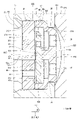
図2に示すように、高圧ポンプ10は、上ハウジング21、下ハウジング22、被固定部25、シリンダ23、ホルダ支持部24、カバー26、プランジャ11、吸入弁部300、電磁駆動部500、吐出通路部700等を備えている。
As shown in FIG. 2, the high-pressure pump 10 includes an upper housing 21, a lower housing 22, a fixed portion 25, a cylinder 23, a holder support portion 24, a cover 26, a plunger 11, an intake valve portion 300, an electromagnetic drive portion 500, and a discharge. It is provided with a passage portion 700 and the like.
上ハウジング21、下ハウジング22、被固定部25、シリンダ23、ホルダ支持部24は、例えばステンレス等の金属により形成されている。ここで、上ハウジング21および下ハウジング22は、「ハウジング」に対応している。
The upper housing 21, the lower housing 22, the fixed portion 25, the cylinder 23, and the holder support portion 24 are made of metal such as stainless steel. Here, the upper housing 21 and the lower housing 22 correspond to “housing”.
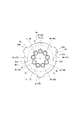
上ハウジング21は、略八角柱状に形成されている。上ハウジング21は、八角筒状のハウジング外周壁270を有している。ハウジング外周壁270は、平面状の平面部271を有している。平面部271は、ハウジング外周壁270の周方向に8つ形成されている(図4参照)。
The upper housing 21 is formed in a substantially octagonal column shape. The upper housing 21 has an octagonal tubular outer peripheral wall 270. The housing outer peripheral wall 270 has a flat surface portion 271. Eight flat surface portions 271 are formed in the circumferential direction of the housing outer peripheral wall 270 (see FIG. 4 ).
上ハウジング21は、穴部211、吸入穴部212、吸入穴部213、吐出穴部214、吐出穴部215を有している。穴部211は、上ハウジング21の中央を上ハウジング21の軸に沿って円筒状に貫くよう形成されている。
The upper housing 21 has a hole portion 211, a suction hole portion 212, a suction hole portion 213, a discharge hole portion 214, and a discharge hole portion 215. The hole portion 211 is formed so as to penetrate the center of the upper housing 21 in a cylindrical shape along the axis of the upper housing 21.
吸入穴部212は、上ハウジング21のハウジング外周壁270の1つの平面部271から穴部211に向かって延びるよう略円筒状に形成されている。吸入穴部213は、吸入穴部212と穴部211とを接続するよう略円筒状に形成されている。吸入穴部212と吸入穴部213とは同軸に形成されている。また、吸入穴部212および吸入穴部213の軸は、穴部211の軸と直交する。吸入穴部213の内径は、吸入穴部212の内径より小さい(図5参照)。上ハウジング21の吸入穴部212および吸入穴部213の内側には、吸入通路216が形成されている。ここで、上ハウジング21は、「吸入通路形成部」に対応している。
The suction hole portion 212 is formed in a substantially cylindrical shape so as to extend from one flat surface portion 271 of the housing outer peripheral wall 270 of the upper housing 21 toward the hole portion 211. The suction hole 213 is formed in a substantially cylindrical shape so as to connect the suction hole 212 and the hole 211. The suction hole portion 212 and the suction hole portion 213 are formed coaxially. The axes of the suction hole 212 and the suction hole 213 are orthogonal to the axis of the hole 211. The inner diameter of the suction hole 213 is smaller than the inner diameter of the suction hole 212 (see FIG. 5). A suction passage 216 is formed inside the suction hole 212 and the suction hole 213 of the upper housing 21. Here, the upper housing 21 corresponds to a “suction passage forming portion”.
吐出穴部214は、上ハウジング21のハウジング外周壁270の吸入穴部212が形成された平面部271とは反対側の平面部271から穴部211に向かって延びるよう略円筒状に形成されている。吐出穴部215は、吐出穴部214と穴部211とを接続するよう略円筒状に形成されている。吐出穴部214と吐出穴部215とは同軸に形成されている。また、吐出穴部214および吐出穴部215の軸は、穴部211の軸と直交する。吐出穴部215の内径は、吐出穴部214の内径より小さい(図6参照)。吐出穴部214および吐出穴部215の内側には、吐出通路217が形成されている。ここで、上ハウジング21の吐出穴部214および吐出穴部215は、「吐出通路形成部」に対応している。また、吐出穴部215は、吐出穴233より小さく、吐出穴部215の中心軸は、吐出穴233の中心軸に対し鉛直方向下側に配置される。
The discharge hole portion 214 is formed in a substantially cylindrical shape so as to extend toward the hole portion 211 from the flat surface portion 271 of the upper housing 21 opposite to the flat surface portion 271 where the suction hole portion 212 is formed. There is. The discharge hole portion 215 is formed in a substantially cylindrical shape so as to connect the discharge hole portion 214 and the hole portion 211. The ejection hole portion 214 and the ejection hole portion 215 are formed coaxially. Further, the axes of the discharge hole portion 214 and the discharge hole portion 215 are orthogonal to the axis of the hole portion 211. The inner diameter of the ejection hole portion 215 is smaller than the inner diameter of the ejection hole portion 214 (see FIG. 6). A discharge passage 217 is formed inside the discharge hole 214 and the discharge hole 215. Here, the discharge hole portion 214 and the discharge hole portion 215 of the upper housing 21 correspond to the “discharge passage forming portion”. The discharge hole portion 215 is smaller than the discharge hole 233, and the central axis of the discharge hole portion 215 is arranged vertically below the central axis of the discharge hole 233.
また、吸入穴部212と吸入穴部213と吐出穴部214と吐出穴部215とは同軸に形成されている。すなわち、吸入穴部212、吸入穴部213、吐出穴部214、吐出穴部215は、同一平面上に軸がある(図2〜4参照)。
The suction hole 212, the suction hole 213, the discharge hole 214, and the discharge hole 215 are formed coaxially. That is, the suction hole 212, the suction hole 213, the discharge hole 214, and the discharge hole 215 have axes on the same plane (see FIGS. 2 to 4 ).
上ハウジング21の下方には、ハウジング凹部210が形成されている。ハウジング凹部210は、上ハウジング21の軸方向の一方の端面から略円筒状に凹むよう形成されている。
A housing recess 210 is formed below the upper housing 21. The housing recess 210 is formed so as to be recessed into a substantially cylindrical shape from one end surface of the upper housing 21 in the axial direction.
下ハウジング22は、略円板状に形成されている。下ハウジング22は、穴部221、穴部222を有している。下ハウジング22の上方には、ハウジング凸部220が形成されている。ハウジング凸部220は、下ハウジング22の一方の面の中央から略円柱状に突出するよう形成されている。
The lower housing 22 is formed in a substantially disc shape. The lower housing 22 has a hole 221 and a hole 222. A housing protrusion 220 is formed above the lower housing 22. The housing protrusion 220 is formed so as to protrude from the center of one surface of the lower housing 22 in a substantially columnar shape.
穴部221は、下ハウジング22およびハウジング凸部220の中央を板厚方向に略円筒状に貫くよう形成されている。なお、穴部221の内径は、穴部211の内径よりやや大きい。穴部222は、下ハウジング22の一方の面のハウジング凸部220の径方向外側の部位と他方の面とを接続するよう穴部221の径方向外側に1つ形成されている。
The hole 221 is formed so as to penetrate through the centers of the lower housing 22 and the housing protrusion 220 in a substantially cylindrical shape in the plate thickness direction. The inner diameter of the hole 221 is slightly larger than the inner diameter of the hole 211. One hole 222 is formed on the outer side of the hole 221 in the radial direction so as to connect the portion of the one surface of the lower housing 22 on the outer side in the radial direction of the housing projection 220 and the other surface.
下ハウジング22は、ハウジング凸部220がハウジング凹部210に嵌合するよう上ハウジング21と一体に設けられている。ハウジング凸部220の外径は、ハウジング凹部210の内径より大きい。そのため、上ハウジング21と下ハウジング22とは、ハウジング凸部220がハウジング凹部210に圧入されることにより固定されている。ここで、上ハウジング21と下ハウジング22とは、上ハウジング21の下ハウジング22側の面と下ハウジング22の上ハウジング21側の面(図2に示す当接部203)において軸方向で当接している。
The lower housing 22 is provided integrally with the upper housing 21 so that the housing protrusion 220 fits into the housing recess 210. The outer diameter of the housing protrusion 220 is larger than the inner diameter of the housing recess 210. Therefore, the upper housing 21 and the lower housing 22 are fixed by press-fitting the housing protrusion 220 into the housing recess 210. Here, the upper housing 21 and the lower housing 22 are in axial contact with each other on the surface of the upper housing 21 on the lower housing 22 side and the surface of the lower housing 22 on the upper housing 21 side (contact portion 203 shown in FIG. 2). ing.
上ハウジング21の下ハウジング22側の面の外縁部には、穴部222の上ハウジング21側の開口を塞がないよう、逃がし部218がテーパ面で形成され、当接部203と逃がし部218を両立させている。
A relief portion 218 is formed as a tapered surface at the outer edge of the lower housing 22 side surface of the upper housing 21 so as not to close the opening of the hole 222 on the upper housing 21 side, and the contact portion 203 and the relief portion 218 are formed. Is compatible.
被固定部25は、下ハウジング22の外縁部から径方向外側へ板状に延びるようにして下ハウジング22と一体に形成されている。つまり、被固定部25は、下ハウジング22および上ハウジング21に接続している。本実施形態では、被固定部25は、下ハウジング22の周方向に等間隔で2つ形成されている。2つの被固定部25は、それぞれ、1つのボルト孔250を有している。ボルト孔250は、被固定部25を板厚方向に貫くよう略円筒状に形成されている。
The fixed portion 25 is formed integrally with the lower housing 22 so as to extend radially outward from the outer edge portion of the lower housing 22 in a plate shape. That is, the fixed portion 25 is connected to the lower housing 22 and the upper housing 21. In this embodiment, two fixed portions 25 are formed at equal intervals in the circumferential direction of the lower housing 22. Each of the two fixed parts 25 has one bolt hole 250. The bolt hole 250 is formed in a substantially cylindrical shape so as to penetrate the fixed portion 25 in the plate thickness direction.
高圧ポンプ10がエンジン1に取り付けられるとき、被固定部25は、ボルト孔250に対応して設けられるボルト100によりエンジン1のエンジンヘッド2に固定される(図2参照)。ボルト100は、軸部101、頭部102を有している。軸部101は、略円柱状に形成されている。軸部101の外径は、ボルト孔250の内径よりやや小さい。
When the high-pressure pump 10 is attached to the engine 1, the fixed portion 25 is fixed to the engine head 2 of the engine 1 by the bolts 100 provided corresponding to the bolt holes 250 (see FIG. 2). The bolt 100 has a shaft portion 101 and a head portion 102. The shaft 101 is formed in a substantially columnar shape. The outer diameter of the shaft portion 101 is slightly smaller than the inner diameter of the bolt hole 250.
頭部102は、軸部101の一方の端部に接続するよう軸部101と一体に形成されている。頭部102の外径は、軸部101の外径より大きい。高圧ポンプ10がエンジン1に取り付けられるとき、ボルト100は、軸部101が被固定部25のボルト孔250に挿通され、エンジンヘッド2の固定穴部120にねじ結合される。このとき、ボルト100の頭部102から被固定部25に対しエンジンヘッド2側への軸力が作用する。なお、ボルト100を締め付けた際に、下ハウジング22をエンジンヘッド2に確実に密着させるため、少なくともボルト100の頭部102周辺の平面度が適切に確保されている。
The head portion 102 is formed integrally with the shaft portion 101 so as to be connected to one end of the shaft portion 101. The outer diameter of the head portion 102 is larger than the outer diameter of the shaft portion 101. When the high-pressure pump 10 is attached to the engine 1, the shaft portion 101 of the bolt 100 is inserted into the bolt hole 250 of the fixed portion 25 and is screwed into the fixing hole portion 120 of the engine head 2. At this time, an axial force is applied from the head portion 102 of the bolt 100 to the fixed portion 25 toward the engine head 2 side. When the bolt 100 is tightened, the lower housing 22 is surely brought into close contact with the engine head 2, so that at least the flatness around the head 102 of the bolt 100 is properly secured.
シリンダ23は、シリンダ穴部231を有している。シリンダ穴部231は、円柱状の部材の一方の端面から他方の端面側へ延びるよう略円筒状に形成されている。すなわち、シリンダ23は、筒部、および、筒部の一端を塞ぐ底部を有する有底筒状に形成されている。シリンダ穴部231の内周壁である筒状内周壁230は、略円筒状に形成されている。筒状内周壁230は、摺動面230a、拡径面230b等を有している。摺動面230aは、筒状内周壁230の開口側において円筒状に形成されている。拡径面230bは、摺動面230aに対し筒状内周壁230の開口とは反対側において円筒状に形成されている。摺動面230aと拡径面230bとは同軸に形成されている。拡径面230bの径は、摺動面230aの径より大きい。
The cylinder 23 has a cylinder hole 231. The cylinder hole 231 is formed in a substantially cylindrical shape so as to extend from one end surface of the cylindrical member to the other end surface side. That is, the cylinder 23 is formed in a bottomed tubular shape having a tubular portion and a bottom portion that closes one end of the tubular portion. The cylindrical inner peripheral wall 230 which is the inner peripheral wall of the cylinder hole 231 is formed in a substantially cylindrical shape. The cylindrical inner peripheral wall 230 has a sliding surface 230a, an enlarged diameter surface 230b, and the like. The sliding surface 230a is formed in a cylindrical shape on the opening side of the cylindrical inner peripheral wall 230. The enlarged diameter surface 230b is formed in a cylindrical shape on the side opposite to the opening of the cylindrical inner peripheral wall 230 with respect to the sliding surface 230a. The sliding surface 230a and the expanded diameter surface 230b are formed coaxially. The diameter of the expanded surface 230b is larger than the diameter of the sliding surface 230a.
シリンダ23の外径は、上ハウジング21の穴部211の内径よりやや大きい。シリンダ23は、下ハウジング22の穴部221を通り、上ハウジング21の穴部211に底部側の外周壁が嵌合するよう上ハウジング21および下ハウジング22と一体に設けられている。シリンダ23は、吸入穴232、吐出穴233を有している。吸入穴232は、シリンダ穴部231の底部側の端部の拡径面230bと上ハウジング21の吸入穴部213とを接続するよう形成されている。吐出穴233は、シリンダ穴部231の底部側の端部の拡径面230bと上ハウジング21の吐出穴部215とを接続するよう形成されている。すなわち、吸入穴232と吐出穴233とは、シリンダ穴部231の筒状内周壁230の軸Ax1を挟んで対向するよう形成されている。つまり、吸入穴232と吐出穴233とは、同一平面上に配置されている(図2〜4参照)。
The outer diameter of the cylinder 23 is slightly larger than the inner diameter of the hole portion 211 of the upper housing 21. The cylinder 23 is provided integrally with the upper housing 21 and the lower housing 22 so as to pass through the hole 221 of the lower housing 22 and the outer peripheral wall on the bottom side fits into the hole 211 of the upper housing 21. The cylinder 23 has a suction hole 232 and a discharge hole 233. The suction hole 232 is formed so as to connect the enlarged diameter surface 230b of the bottom end of the cylinder hole 231 and the suction hole 213 of the upper housing 21. The discharge hole 233 is formed so as to connect the enlarged diameter surface 230b at the bottom end of the cylinder hole 231 and the discharge hole 215 of the upper housing 21. That is, the suction hole 232 and the discharge hole 233 are formed so as to face each other with the axis Ax1 of the cylindrical inner peripheral wall 230 of the cylinder hole portion 231 interposed therebetween. That is, the suction hole 232 and the discharge hole 233 are arranged on the same plane (see FIGS. 2 to 4).
ホルダ支持部24は、下ハウジング22の穴部221の径方向外側の部位から上ハウジング21とは反対側に略円筒状に延びるようにして形成されている。本実施形態では、ホルダ支持部24は、下ハウジング22と一体に形成されている。ホルダ支持部24は、シリンダ23の一端の径方向外側においてシリンダ23と同軸になるよう形成されている。高圧ポンプ10がエンジン1に取り付けられるとき、ホルダ支持部24は、エンジンヘッド2に形成された取付穴部3に挿入される(図2参照)。
The holder support portion 24 is formed so as to extend in a substantially cylindrical shape from a portion radially outside the hole portion 221 of the lower housing 22 to the side opposite to the upper housing 21. In the present embodiment, the holder support portion 24 is formed integrally with the lower housing 22. The holder support portion 24 is formed so as to be coaxial with the cylinder 23 on the radially outer side of one end of the cylinder 23. When the high pressure pump 10 is attached to the engine 1, the holder support portion 24 is inserted into the attachment hole portion 3 formed in the engine head 2 (see FIG. 2 ).
プランジャ11は、例えばステンレス等の金属により略円柱状に形成されている。プランジャ11は、大径部111、小径部112を有している。小径部112は、外径が大径部111の外径より小さい。プランジャ11は、大径部111側がシリンダ23のシリンダ穴部231に挿入されるようにして設けられている。シリンダ穴部231の底壁および筒状内周壁230の拡径面230bとプランジャ11の大径部111側の端部との間に加圧室200が形成されている。すなわち、シリンダ23は、加圧室200を形成している。また、シリンダ23は、加圧室200を形成する筒状の筒状内周壁230を有している。ここで、シリンダ23は、「加圧室形成部」に対応している。加圧室200は、吸入穴232および吐出穴233に接続している。
The plunger 11 is made of a metal such as stainless steel and has a substantially cylindrical shape. The plunger 11 has a large diameter portion 111 and a small diameter portion 112. The outer diameter of the small diameter portion 112 is smaller than the outer diameter of the large diameter portion 111. The plunger 11 is provided so that the large diameter portion 111 side is inserted into the cylinder hole portion 231 of the cylinder 23. The pressurizing chamber 200 is formed between the bottom wall of the cylinder hole 231 and the enlarged diameter surface 230b of the cylindrical inner peripheral wall 230 and the end of the plunger 11 on the large diameter portion 111 side. That is, the cylinder 23 forms the pressurizing chamber 200. Further, the cylinder 23 has a cylindrical inner peripheral wall 230 that forms the pressurizing chamber 200. Here, the cylinder 23 corresponds to a "pressurizing chamber forming portion". The pressurizing chamber 200 is connected to the suction hole 232 and the discharge hole 233.
プランジャ11の外径は、シリンダ23の内径、すなわち、シリンダ穴部231の内径よりやや小さく形成されている。そのため、プランジャ11は、大径部111の外周壁がシリンダ穴部231の筒状内周壁230の摺動面230aと摺動しつつ、シリンダ穴部231内を軸方向に往復移動可能である。プランジャ11がシリンダ穴部231内を往復移動するとき、加圧室200の容積が増減する。このように、プランジャ11は、一端が加圧室200に位置するよう筒状内周壁230の内側において軸方向に往復移動可能に設けられている。
The outer diameter of the plunger 11 is formed slightly smaller than the inner diameter of the cylinder 23, that is, the inner diameter of the cylinder hole 231. Therefore, the plunger 11 can reciprocate in the cylinder hole 231 in the axial direction while the outer peripheral wall of the large diameter portion 111 slides on the sliding surface 230a of the cylindrical inner peripheral wall 230 of the cylinder hole 231. When the plunger 11 reciprocates in the cylinder hole 231, the volume of the pressurizing chamber 200 increases or decreases. In this way, the plunger 11 is provided so as to be reciprocally movable in the axial direction inside the cylindrical inner peripheral wall 230 so that one end thereof is located in the pressurizing chamber 200.
本実施形態では、ホルダ支持部24の内側にシールホルダ14が設けられている。シールホルダ14は、例えばステンレス等の金属により筒状に形成されている。シールホルダ14は、外壁がホルダ支持部24の内壁に嵌合するよう設けられている。シリンダ23とシールホルダ14との間に中間筒部材241が設けられている。中間筒部材241は、略円筒状に形成され、シリンダ23と同軸に設けられている。中間筒部材241の内径は、シリンダ穴部231の内径より大きい。また、中間筒部材241には、内周壁と外周壁とを接続する穴部242が形成されている。穴部242は、中間筒部材241の周方向に複数形成されている。
In this embodiment, the seal holder 14 is provided inside the holder support 24. The seal holder 14 is formed of a metal such as stainless steel in a tubular shape. The seal holder 14 is provided so that the outer wall fits into the inner wall of the holder support portion 24. An intermediate tubular member 241 is provided between the cylinder 23 and the seal holder 14. The intermediate tubular member 241 is formed in a substantially cylindrical shape and is provided coaxially with the cylinder 23. The inner diameter of the intermediate tubular member 241 is larger than the inner diameter of the cylinder hole 231. Further, the intermediate cylindrical member 241 is formed with a hole 242 that connects the inner peripheral wall and the outer peripheral wall. A plurality of holes 242 are formed in the circumferential direction of the intermediate tubular member 241.
シールホルダ14は、内壁と中間筒部材241のシリンダ23とは反対側の端面とプランジャ11の小径部112の外周壁との間に略円筒状の空間を形成するよう設けられている。当該空間には、環状のシール141が設けられている。シール141は、径内側のフッ素樹脂製のリングと径外側のゴム製のリングとからなる。シール141により、プランジャ11の小径部112周囲の燃料油膜の厚さが調整され、エンジン1への燃料のリークが抑制される。また、シールホルダ14のシリンダ23とは反対側の端部には、オイルシール142が設けられている。オイルシール142により、プランジャ11の小径部112の周囲のオイル油膜の厚さが調整され、オイルのリークが抑制される。なお、プランジャ11の大径部111と小径部112との間の段差面と中間筒部材241およびシール141との間には、プランジャ11の往復移動時に容積が変化する可変容積室201が形成されている。
The seal holder 14 is provided so as to form a substantially cylindrical space between the inner wall, the end surface of the intermediate tubular member 241 opposite to the cylinder 23, and the outer peripheral wall of the small diameter portion 112 of the plunger 11. An annular seal 141 is provided in the space. The seal 141 is composed of a fluororesin ring on the inner diameter side and a rubber ring on the outer diameter side. The thickness of the fuel oil film around the small-diameter portion 112 of the plunger 11 is adjusted by the seal 141, and fuel leakage to the engine 1 is suppressed. An oil seal 142 is provided at the end of the seal holder 14 opposite to the cylinder 23. The oil seal 142 adjusts the thickness of the oil film around the small diameter portion 112 of the plunger 11 to suppress oil leakage. A variable volume chamber 201 whose volume changes when the plunger 11 reciprocates is formed between the step surface between the large diameter portion 111 and the small diameter portion 112 of the plunger 11 and the intermediate tubular member 241 and the seal 141. ing.
ここで、下ハウジング22とシリンダ23の外周壁とホルダ支持部24の内周壁とシールホルダ14との間に環状の空間である環状空間202が形成されている。環状空間202は、下ハウジング22の穴部222に接続している。また、環状空間202は、シールホルダ14の内周壁とシリンダ23の外周壁および中間筒部材241の外周壁との間の円筒状の空間、ならびに、穴部242を経由して可変容積室201に接続している。
Here, an annular space 202, which is an annular space, is formed between the lower housing 22, the outer peripheral wall of the cylinder 23, the inner peripheral wall of the holder support portion 24, and the seal holder 14. The annular space 202 is connected to the hole 222 of the lower housing 22. The annular space 202 is a cylindrical space between the inner peripheral wall of the seal holder 14, the outer peripheral wall of the cylinder 23, and the outer peripheral wall of the intermediate tubular member 241, as well as the variable volume chamber 201 via the hole 242. Connected.
プランジャ11の小径部112の大径部111とは反対側の端部には、略円板状のスプリングシート12が設けられている。シールホルダ14とスプリングシート12との間には、スプリング13が設けられている。スプリング13は、例えばコイルスプリングであり、一端がスプリングシート12に当接し、他端がスペーサ140を介してシールホルダ14に当接するよう設けられている。シールホルダ14は溶接可能な材料であるため硬度が比較的低く、比較的硬度の高いスペーサ140を介することで、シールホルダ14の摩耗を抑制する。スプリング13は、スプリングシート12を経由してプランジャ11を加圧室200とは反対側に付勢している。高圧ポンプ10は、エンジン1のエンジンヘッド2に取り付けられるとき、プランジャ11の小径部112の大径部111とは反対側の端部にリフタ5が取り付けられる。
A substantially disc-shaped spring seat 12 is provided at an end of the small diameter portion 112 of the plunger 11 opposite to the large diameter portion 111. A spring 13 is provided between the seal holder 14 and the spring seat 12. The spring 13 is, for example, a coil spring, one end of which is in contact with the spring seat 12 and the other end of which is in contact with the seal holder 14 via the spacer 140. Since the seal holder 14 is a weldable material, the seal holder 14 has relatively low hardness, and wear of the seal holder 14 is suppressed through the spacer 140 having relatively high hardness. The spring 13 biases the plunger 11 to the side opposite to the pressurizing chamber 200 via the spring seat 12. When the high pressure pump 10 is attached to the engine head 2 of the engine 1, the lifter 5 is attached to the end of the small diameter portion 112 of the plunger 11 opposite to the large diameter portion 111.
高圧ポンプ10がエンジン1に取り付けられたとき、リフタ5は、エンジン1の駆動軸に連動して回転するカム軸のカム4に当接する。これにより、エンジン1が回転しているとき、カム4の回転により、プランジャ11が軸方向に往復移動する。このとき、加圧室200および可変容積室201の容積は、それぞれ周期的に変化する。
When the high-pressure pump 10 is attached to the engine 1, the lifter 5 comes into contact with the cam 4 of the cam shaft that rotates in conjunction with the drive shaft of the engine 1. Accordingly, when the engine 1 is rotating, the rotation of the cam 4 causes the plunger 11 to reciprocate in the axial direction. At this time, the volumes of the pressurizing chamber 200 and the variable volume chamber 201 change periodically.
図2に示すように、プランジャ11が下死点にあるとき、プランジャ11の大径部111の外周壁の小径部112とは反対側の端部は、摺動面230aの拡径面230b側の端部に対し拡径面230b側に位置している。また、このとき、プランジャ11の大径部111の外周壁の小径部112側の端部は、摺動面230aの拡径面230bとは反対側の端部に対し拡径面230bとは反対側に位置している。
As shown in FIG. 2, when the plunger 11 is at the bottom dead center, the end of the large-diameter portion 111 of the plunger 11 on the side opposite to the small-diameter portion 112 of the outer peripheral wall of the plunger 11 is on the expanded surface 230b side of the sliding surface 230a. Is located on the side of the enlarged diameter surface 230b with respect to the end portion of. At this time, the end of the outer peripheral wall of the large-diameter portion 111 of the plunger 11 on the side of the small-diameter portion 112 is opposite to the end of the sliding surface 230a on the side opposite to the diameter-enlarged surface 230b. Located on the side.
図3に示すように、プランジャ11が上死点にあるとき、プランジャ11の大径部111の外周壁の小径部112とは反対側の端部は、摺動面230aの拡径面230b側の端部に対し拡径面230b側に位置している。また、このとき、プランジャ11の大径部111の外周壁の小径部112側の端部は、摺動面230aの拡径面230bとは反対側の端部に対し拡径面230bとは反対側に位置している。
As shown in FIG. 3, when the plunger 11 is at the top dead center, the end of the large-diameter portion 111 of the plunger 11 on the side opposite to the small-diameter portion 112 of the large-diameter portion 111 has the sliding surface 230a on the expanded surface 230b side. Is located on the side of the enlarged diameter surface 230b with respect to the end portion of. At this time, the end of the outer peripheral wall of the large-diameter portion 111 of the plunger 11 on the side of the small-diameter portion 112 is opposite to the end of the sliding surface 230a on the side opposite to the diameter-enlarged surface 230b. Located on the side.
上述のように、プランジャ11が下死点から上死点までのどの位置にあっても、プランジャ11の大径部111の外周壁の小径部112とは反対側の端部は、摺動面230aの拡径面230b側の端部に対し拡径面230b側に位置し、プランジャ11の大径部111の外周壁の小径部112側の端部は、摺動面230aの拡径面230bとは反対側の端部に対し拡径面230bとは反対側に位置している。
As described above, regardless of where the plunger 11 is located from the bottom dead center to the top dead center, the end portion of the outer peripheral wall of the large diameter portion 111 of the plunger 11 opposite to the small diameter portion 112 has a sliding surface. The end of the outer peripheral wall of the large diameter portion 111 of the plunger 11 on the side of the small diameter portion 112 is located on the side of the diameter enlarged surface 230b of the sliding surface 230b of the sliding surface 230a. It is located on the side opposite to the enlarged diameter surface 230b with respect to the end on the side opposite to.
カバー26は、例えばステンレス等の金属により形成されている。カバー26は、カバー筒部261、カバー底部262等を有している。カバー筒部261は、略八角筒状に形成されている。カバー筒部261は、八角筒状のカバー外周壁280を有している。カバー外周壁280は、平面状の平面部281を有している。平面部281は、カバー外周壁280の周方向に8つ形成されている。
The cover 26 is made of metal such as stainless steel. The cover 26 has a cover cylinder portion 261, a cover bottom portion 262, and the like. The cover tubular portion 261 is formed into a substantially octagonal tubular shape. The cover tubular portion 261 has an octagonal tubular outer peripheral wall 280. The cover outer peripheral wall 280 has a flat surface portion 281. Eight flat surface portions 281 are formed in the circumferential direction of the cover outer peripheral wall 280.
カバー底部262は、カバー筒部261の一端を塞ぐようカバー筒部261と一体に形成されている。すなわち、カバー26は、有底筒状に形成されている。なお、本実施形態では、カバー26は、例えば板状の部材をプレス加工することにより形成されている。そのため、カバー26は、肉厚が比較的小さい。なお、カバー26は、高圧室を形成しないため、肉厚を小さくできる。
The cover bottom portion 262 is formed integrally with the cover tubular portion 261 so as to close one end of the cover tubular portion 261. That is, the cover 26 is formed in a bottomed tubular shape. In the present embodiment, the cover 26 is formed by pressing a plate-shaped member, for example. Therefore, the cover 26 has a relatively small wall thickness. Since the cover 26 does not form a high pressure chamber, the wall thickness can be reduced.
カバー26は、カバー穴部265、カバー穴部266、カバー穴部267を有している。カバー穴部265は、カバー底部262の中央を板厚方向に貫くよう略円筒状に形成されている。カバー穴部266、カバー穴部267は、それぞれ、カバー筒部261の内周壁と外周壁すなわちカバー外周壁280の平面部281とを接続するよう略円筒状に形成されている。カバー穴部266とカバー穴部267とは、カバー筒部261の軸を挟んで対向するよう略同軸に形成されている。
The cover 26 has a cover hole 265, a cover hole 266, and a cover hole 267. The cover hole portion 265 is formed in a substantially cylindrical shape so as to penetrate the center of the cover bottom portion 262 in the plate thickness direction. The cover hole portion 266 and the cover hole portion 267 are each formed in a substantially cylindrical shape so as to connect the inner peripheral wall of the cover tubular portion 261 and the outer peripheral wall, that is, the flat surface portion 281 of the cover outer peripheral wall 280. The cover hole portion 266 and the cover hole portion 267 are formed substantially coaxially so as to face each other with the axis of the cover cylinder portion 261 interposed therebetween.
カバー26は、内側に上ハウジング21を収容し、カバー筒部261のカバー底部262とは反対側の端部が、下ハウジング22の上ハウジング21側の面に当接するよう設けられている。カバー26は、上ハウジング21、下ハウジング22、シリンダ23との間に燃料室260を形成している。ここで、カバー筒部261の端部と下ハウジング22とは、例えば溶接により周方向の全域に亘り接合されている。これにより、カバー筒部261と下ハウジング22との間は、液密に保たれている。また、カバー26は、カバー穴部266と上ハウジング21の吸入穴部212とが対応し、カバー穴部267と上ハウジング21の吐出穴部214とが対応するよう設けられている。カバー26の頭頂部、すなわち、カバー底部262から作動音が放射されるため、カバー底部262の剛性を高くすることが望ましい。本実施形態では、カバー底部262の形状をドーム形状とすることにより、カバー底部262の剛性を高くしているが、カバー底部262を平面状に形成し、リブ等を設けることにより剛性を高くしてもよい。
The cover 26 accommodates the upper housing 21 inside, and the end of the cover tubular portion 261 opposite to the cover bottom portion 262 is provided so as to contact the surface of the lower housing 22 on the upper housing 21 side. The cover 26 forms a fuel chamber 260 between the upper housing 21, the lower housing 22, and the cylinder 23. Here, the end portion of the cover tubular portion 261 and the lower housing 22 are joined to each other by, for example, welding over the entire area in the circumferential direction. As a result, the space between the cover tubular portion 261 and the lower housing 22 is kept liquid-tight. The cover 26 is provided so that the cover hole 266 and the suction hole 212 of the upper housing 21 correspond to each other, and the cover hole 267 and the discharge hole 214 of the upper housing 21 correspond to each other. Since the operating sound is emitted from the top of the cover 26, that is, the cover bottom 262, it is desirable to increase the rigidity of the cover bottom 262. In the present embodiment, the cover bottom portion 262 has a dome shape to increase the rigidity of the cover bottom portion 262. However, the cover bottom portion 262 is formed in a flat shape, and ribs or the like are provided to increase the rigidity. May be.
このように、カバー26は、シリンダ23、上ハウジング21および下ハウジング22の少なくとも一部を覆い、シリンダ23、上ハウジング21および下ハウジング22との間に燃料室260を形成している。なお、燃料室260は、カバー筒部261の内周壁とハウジング外周壁270との間において略八角筒状に形成されている。
In this way, the cover 26 covers at least a part of the cylinder 23, the upper housing 21, and the lower housing 22, and forms the fuel chamber 260 between the cylinder 23, the upper housing 21, and the lower housing 22. The fuel chamber 260 is formed in a substantially octagonal tubular shape between the inner peripheral wall of the cover tubular portion 261 and the outer peripheral wall 270 of the housing.
カバー26には、供給通路部29が設けられている。供給通路部29は、筒状に形成され、一端がカバー底部262のカバー穴部265の周囲の外壁に接続するよう設けられている。供給通路部29は、内側の空間が、カバー穴部265を経由して燃料室260に連通するよう設けられている。ここで、供給通路部29とカバー底部262とは、供給通路部29の周方向の全域に亘り溶接されている。供給通路部29の他端には、供給燃料配管7が接続される。これにより、燃料ポンプ133から吐出される燃料は、供給燃料配管7、供給通路部29を経由して燃料室260に流入する。
The cover 26 is provided with a supply passage portion 29. The supply passage portion 29 is formed in a tubular shape, and one end thereof is provided so as to be connected to an outer wall around the cover hole portion 265 of the cover bottom portion 262. The supply passage portion 29 is provided so that the inner space communicates with the fuel chamber 260 via the cover hole portion 265. Here, the supply passage portion 29 and the cover bottom portion 262 are welded over the entire area of the supply passage portion 29 in the circumferential direction. The supply fuel pipe 7 is connected to the other end of the supply passage portion 29. As a result, the fuel discharged from the fuel pump 133 flows into the fuel chamber 260 via the supply fuel pipe 7 and the supply passage portion 29.
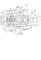
図5に示すように、吸入弁部300は、上ハウジング21の吸入穴部212、吸入穴部213の内側、すなわち、吸入通路216に設けられている。吸入弁部300は、シート部材31、ストッパ35、弁部材40、スプリング39等を有している。
As shown in FIG. 5, the suction valve portion 300 is provided inside the suction hole portion 212 and the suction hole portion 213 of the upper housing 21, that is, in the suction passage 216. The intake valve unit 300 includes a seat member 31, a stopper 35, a valve member 40, a spring 39 and the like.
シート部材31は、例えばステンレス等の金属により略円板状に形成されている。シート部材31は、吸入穴部212の内側において吸入穴部212と略同軸となるよう吸入通路216に設けられている。ここで、シート部材31の外周壁は、吸入穴部212の内周壁に圧入されている。
The sheet member 31 is formed of a metal such as stainless steel into a substantially disc shape. The seat member 31 is provided in the suction passage 216 so as to be substantially coaxial with the suction hole 212 inside the suction hole 212. Here, the outer peripheral wall of the sheet member 31 is press-fitted into the inner peripheral wall of the suction hole portion 212.
シート部材31は、連通路32、連通路33、弁座310を有している。連通路32は、シート部材31の中央においてシート部材31の一方の面と他方の面とを連通するよう略円筒状に形成されている。ここで、連通路32は、シート部材31と略同軸となるよう形成されている。
The seat member 31 includes a communication passage 32, a communication passage 33, and a valve seat 310. The communication passage 32 is formed in a substantially cylindrical shape in the center of the sheet member 31 so as to connect one surface of the sheet member 31 and the other surface thereof. Here, the communication passage 32 is formed so as to be substantially coaxial with the seat member 31.
連通路33は、連通路32の径方向外側においてシート部材31の一方の面と他方の面とを連通するよう略円筒状に形成されている。連通路33は、シート部材31の周方向に複数形成されている。本実施形態では、連通路33は、例えば12個が等間隔に形成されている。連通路33が等間隔に形成されているため、燃料流れが均一になり、後述する弁部材40の挙動が安定する。なお、連通路33は、シート部材31の軸を中心とする仮想円上に配置されている。
The communication passage 33 is formed in a substantially cylindrical shape so that one surface of the sheet member 31 and the other surface thereof communicate with each other on the outer side in the radial direction of the communication passage 32. A plurality of communication passages 33 are formed in the circumferential direction of the sheet member 31. In this embodiment, for example, twelve communication passages 33 are formed at equal intervals. Since the communication passages 33 are formed at equal intervals, the fuel flow becomes uniform, and the behavior of the valve member 40 described later becomes stable. The communication passage 33 is arranged on a virtual circle centered on the axis of the sheet member 31.
弁座310は、シート部材31の加圧室200側の面において、連通路32、および、複数の連通路33それぞれの周囲に環状に形成されている。すなわち、弁座310は、シート部材31の加圧室200側の面において、複数形成されている。
The valve seat 310 is formed in an annular shape around the communication passage 32 and the plurality of communication passages 33 on the surface of the seat member 31 on the pressurizing chamber 200 side. That is, a plurality of valve seats 310 are formed on the surface of the seat member 31 on the pressurizing chamber 200 side.
ストッパ35は、例えばステンレス等の金属により形成されている。ストッパ35は、吸入通路216においてシート部材31に対し加圧室200側に設けられている。ストッパ35は、ストッパ小径部36、ストッパ大径部37、ストッパ凹部351、ストッパ凹部352、ストッパ凸部353、連通穴38等を有している。
The stopper 35 is made of metal such as stainless steel. The stopper 35 is provided on the pressurizing chamber 200 side with respect to the seat member 31 in the suction passage 216. The stopper 35 has a small stopper diameter portion 36, a large stopper diameter portion 37, a stopper concave portion 351, a stopper concave portion 352, a stopper convex portion 353, a communication hole 38, and the like.
ストッパ小径部36は、略円柱状に形成されている。ストッパ小径部36の外径は、吸入穴部213の内径よりやや小さい。ストッパ大径部37は、略円柱状に形成されている。ストッパ大径部37の外径は、ストッパ小径部36の外径より大きく、吸入穴部212の内径よりやや小さい。ストッパ大径部37は、ストッパ小径部36の加圧室200とは反対側においてストッパ小径部36と同軸となるようストッパ小径部36と一体に形成されている。
The stopper small diameter portion 36 is formed in a substantially columnar shape. The outer diameter of the stopper small diameter portion 36 is slightly smaller than the inner diameter of the suction hole portion 213. The large-diameter stopper portion 37 is formed in a substantially columnar shape. The outer diameter of the stopper large diameter portion 37 is larger than the outer diameter of the stopper small diameter portion 36 and slightly smaller than the inner diameter of the suction hole portion 212. The large-diameter stopper portion 37 is formed integrally with the small-diameter portion 36 so as to be coaxial with the small-diameter portion 36 on the side of the small-diameter stopper portion 36 opposite to the pressurizing chamber 200.
ストッパ35は、ストッパ小径部36が吸入穴部213の内側に位置し、ストッパ大径部37が吸入穴部212の内側に位置するよう吸入通路216に設けられている。すなわち、ストッパ35は、吸入穴部212および吸入穴部213の内側において吸入穴部212および吸入穴部213と略同軸となるよう吸入通路216に設けられている。
The stopper 35 is provided in the suction passage 216 so that the stopper small diameter portion 36 is located inside the suction hole portion 213 and the stopper large diameter portion 37 is located inside the suction hole portion 212. That is, the stopper 35 is provided in the suction passage 216 so as to be substantially coaxial with the suction hole 212 and the suction hole 213 inside the suction hole 212 and the suction hole 213.
ここで、ストッパ小径部36とストッパ大径部37との間の環状の段差面は、吸入穴部212と吸入穴部213との間の環状の段差面に当接している。これにより、ストッパ35は、加圧室200側への移動が規制されている。
Here, the annular step surface between the small stopper diameter portion 36 and the large stopper diameter portion 37 is in contact with the annular step surface between the suction hole portion 212 and the suction hole portion 213. As a result, the stopper 35 is restricted from moving toward the pressurizing chamber 200.
また、ストッパ35のストッパ大径部37の加圧室200とは反対側の面は、シート部材31の加圧室200側の面に当接している。これにより、ストッパ35は、加圧室200とは反対側への移動が規制されている。
Further, the surface of the stopper large diameter portion 37 of the stopper 35 opposite to the pressurizing chamber 200 is in contact with the surface of the sheet member 31 on the pressurizing chamber 200 side. As a result, the stopper 35 is restricted from moving to the side opposite to the pressurizing chamber 200.
ストッパ凹部351は、ストッパ大径部37のシート部材31側の面から加圧室200側へ略円筒状に凹むよう形成されている。ここで、ストッパ凹部351は、ストッパ大径部37と略同軸となるよう形成されている。ストッパ凹部351の内径は、ストッパ大径部37の外径より小さく、ストッパ小径部36の外径より大きい。
The stopper recess 351 is formed so as to be recessed in a substantially cylindrical shape from the surface of the large-diameter stopper portion 37 on the sheet member 31 side toward the pressurizing chamber 200. Here, the stopper recess 351 is formed so as to be substantially coaxial with the stopper large diameter portion 37. The inner diameter of the stopper recess 351 is smaller than the outer diameter of the stopper large diameter portion 37 and larger than the outer diameter of the stopper small diameter portion 36.
ストッパ凹部352は、ストッパ凹部351の底面から加圧室200側へ略円筒状に凹むよう形成されている。ここで、ストッパ凹部352は、ストッパ凹部351と略同軸となるよう形成されている。ストッパ凹部352の内径は、ストッパ凹部351の内径およびストッパ小径部36の外径より小さい。
The stopper recess 352 is formed so as to be recessed in a substantially cylindrical shape from the bottom surface of the stopper recess 351 toward the pressurizing chamber 200 side. Here, the stopper recess 352 is formed so as to be substantially coaxial with the stopper recess 351. The inner diameter of the stopper recess 352 is smaller than the inner diameter of the stopper recess 351 and the outer diameter of the stopper small diameter portion 36.
ストッパ凸部353は、ストッパ凹部352の底面の中央からシート部材31側へ略円柱状に突出するよう形成されている。ここで、ストッパ凸部353は、ストッパ凹部352と略同軸となるよう形成されている。また、ストッパ凸部353のシート部材31側の端面は、ストッパ凹部351の底面よりもシート部材31側に位置している。
The stopper protrusion 353 is formed so as to protrude from the center of the bottom surface of the stopper recess 352 toward the sheet member 31 in a substantially columnar shape. Here, the stopper protrusion 353 is formed to be substantially coaxial with the stopper recess 352. The end surface of the stopper protrusion 353 on the sheet member 31 side is positioned closer to the sheet member 31 than the bottom surface of the stopper recess 351.
連通穴38は、ストッパ凸部353の径方向外側においてストッパ凹部352の底面とストッパ小径部36の加圧室200側の面とを連通するよう略円筒状に形成されている。連通穴38は、ストッパ小径部36の周方向に等間隔で複数形成されている。本実施形態では、連通穴38は、例えば4個形成されている。なお、連通穴38は、ストッパ小径部36の軸を中心とする仮想円上に配置されている。
The communication hole 38 is formed in a substantially cylindrical shape so as to communicate the bottom surface of the stopper recess 352 and the surface of the stopper small diameter portion 36 on the pressurizing chamber 200 side on the outer side in the radial direction of the stopper protrusion 353. A plurality of communication holes 38 are formed at equal intervals in the circumferential direction of the stopper small diameter portion 36. In this embodiment, for example, four communication holes 38 are formed. The communication hole 38 is arranged on a virtual circle centered on the axis of the stopper small diameter portion 36.
シート部材31の連通路32、連通路33、ストッパ35のストッパ凹部351、ストッパ凹部352、連通穴38には吸入通路216が形成されている。そのため、燃料室260の燃料は、連通路32、連通路33、ストッパ凹部351、ストッパ凹部352、連通穴38に形成された吸入通路216、および、吸入穴232を経由して加圧室200に流入可能である。
A suction passage 216 is formed in the communication passage 32, the communication passage 33 of the seat member 31, the stopper recess 351, the stopper recess 352 of the stopper 35, and the communication hole 38. Therefore, the fuel in the fuel chamber 260 enters the pressurizing chamber 200 via the communication passage 32, the communication passage 33, the stopper recess 351, the stopper recess 352, the suction passage 216 formed in the communication hole 38, and the suction hole 232. Inflow is possible.
弁部材40は、ストッパ凹部351の内側、すなわち、シート部材31の加圧室200側に設けられている。弁部材40は、バルブ本体41、テーパ部42、ガイド部43、連通孔44を有している。バルブ本体41、テーパ部42、ガイド部43は、例えばステンレス等の金属により一体に形成されている。バルブ本体41は、略円板状に形成されている。
The valve member 40 is provided inside the stopper recess 351, that is, on the pressurizing chamber 200 side of the seat member 31. The valve member 40 has a valve body 41, a tapered portion 42, a guide portion 43, and a communication hole 44. The valve body 41, the tapered portion 42, and the guide portion 43 are integrally formed of metal such as stainless steel. The valve body 41 is formed in a substantially disc shape.
テーパ部42は、バルブ本体41の径方向外側においてバルブ本体41と一体に略円環状に形成されている。テーパ部42は、加圧室200側の面がシート部材31側から加圧室200側へ向かうに従いバルブ本体41の軸Ax2に近づくようテーパ状に形成されている。
The taper portion 42 is formed in a substantially annular shape integrally with the valve body 41 on the outside in the radial direction of the valve body 41. The taper portion 42 is formed in a taper shape so that the surface on the pressurizing chamber 200 side approaches the axis Ax2 of the valve body 41 from the seat member 31 side toward the pressurizing chamber 200 side.
ガイド部43は、テーパ部42を周方向において複数に分断するようバルブ本体41から径方向外側に突出し、バルブ本体41およびテーパ部42と一体に形成されている。本実施形態では、ガイド部43は、テーパ部42を周方向において、例えば3つに分断するようバルブ本体41の周方向に等間隔で3つ形成されている。ここで、ガイド部43のバルブ本体41とは反対側の端部は、テーパ部42の外縁部よりも径方向外側に位置している。ガイド部43は、バルブ本体41とは反対側の端部がストッパ凹部351の内周壁と摺動することで弁部材40の軸方向の移動を案内可能である。
The guide portion 43 projects radially outward from the valve body 41 so as to divide the tapered portion 42 into a plurality of pieces in the circumferential direction, and is formed integrally with the valve body 41 and the tapered portion 42. In the present embodiment, three guide portions 43 are formed at equal intervals in the circumferential direction of the valve body 41 so as to divide the tapered portion 42 into, for example, three in the circumferential direction. Here, the end portion of the guide portion 43 on the side opposite to the valve body 41 is located radially outside the outer edge portion of the tapered portion 42. The guide portion 43 can guide the axial movement of the valve member 40 by sliding the end portion on the opposite side of the valve body 41 with the inner peripheral wall of the stopper recess 351.
連通孔44は、バルブ本体41の一方の面と他方の面とを連通するよう形成されている。連通孔44は、バルブ本体41の周方向に等間隔で複数形成されている。本実施形態では、連通孔44は、例えば9個形成されている。連通孔44は、バルブ本体41の軸Ax2を中心とする仮想円上に配置されている。
The communication hole 44 is formed so that one surface of the valve body 41 and the other surface thereof communicate with each other. A plurality of communication holes 44 are formed at equal intervals in the circumferential direction of the valve body 41. In this embodiment, for example, nine communication holes 44 are formed. The communication hole 44 is arranged on a virtual circle centered on the axis Ax2 of the valve body 41.
弁部材40のバルブ本体41およびガイド部43における板厚は、シート部材31の加圧室200側の面とストッパ凸部353のシート部材31側の端面との距離より小さい。
弁部材40は、シート部材31側の面がシート部材31の加圧室200側の面、すなわち、複数の弁座310に当接可能であり、ストッパ35側の面の中央がストッパ凸部353のシート部材31側の端面に当接可能である。
The plate thickness of the valve body 41 and the guide portion 43 of the valve member 40 is smaller than the distance between the surface of the seat member 31 on the pressurizing chamber 200 side and the end surface of the stopper protrusion 353 on the seat member 31 side.
The surface of the valve member 40 on the side of the seat member 31 can contact the surface of the seat member 31 on the side of the pressurizing chamber 200, that is, a plurality of valve seats 310, and the center of the surface on the side of the stopper 35 is the stopper protrusion 353. It is possible to contact the end surface of the sheet member 31 side.
弁部材40は、バルブ本体41およびガイド部43における板厚と、シート部材31の加圧室200側の面とストッパ凸部353のシート部材31側の端面との距離との差分の範囲で軸方向に往復移動可能である。
弁部材40は、シート部材31側の面がシート部材31の加圧室200側の面、すなわち、複数の弁座310から離間すると開弁し連通路32、連通路33における燃料の流れを許容し、シート部材31側の面が複数の弁座310に当接すると閉弁し連通路33における燃料の流れを規制可能である。このように、弁部材40は、複数の弁座310に当接するマルチシートタイプの弁体である。
The valve member 40 has an axis within the range of the difference between the plate thickness of the valve body 41 and the guide portion 43 and the distance between the surface of the seat member 31 on the pressurizing chamber 200 side and the end surface of the stopper protrusion 353 on the seat member 31 side. It can be reciprocated in any direction.
The valve member 40 opens when the surface on the side of the seat member 31 separates from the surface on the side of the pressurizing chamber 200 of the seat member 31, that is, the plurality of valve seats 310, and allows the flow of fuel in the communication passages 32 and 33. However, when the surface on the side of the seat member 31 contacts the plurality of valve seats 310, the valve is closed and the flow of fuel in the communication passage 33 can be regulated. As described above, the valve member 40 is a multi-seat type valve body that abuts the plurality of valve seats 310.
弁部材40が開弁すると、連通路32および連通路33と連通孔44およびストッパ凹部351との間の燃料の流れが許容され、燃料室260側の燃料は、連通路32、連通路33、連通孔44、ストッパ凹部351、ストッパ凹部352、連通穴38、吸入穴232を経由して加圧室200側に流れることができる。また、加圧室200側の燃料は、吸入穴232、連通穴38、ストッパ凹部352、ストッパ凹部351、連通孔44、連通路33、連通路32を経由して燃料室260側に流れることができる。このとき、燃料は、弁部材40の連通孔44、および、弁部材40の周囲を流れる。
When the valve member 40 is opened, the flow of fuel between the communication passage 32 and the communication passage 33 and the communication hole 44 and the stopper recess 351 is allowed, and the fuel on the fuel chamber 260 side is connected to the communication passage 32, the communication passage 33, and the fuel. It can flow to the pressurizing chamber 200 side via the communication hole 44, the stopper recess 351, the stopper recess 352, the communication hole 38, and the suction hole 232. Further, the fuel on the pressure chamber 200 side may flow to the fuel chamber 260 side via the suction hole 232, the communication hole 38, the stopper recess 352, the stopper recess 351, the communication hole 44, the communication passage 33, and the communication passage 32. it can. At this time, the fuel flows around the communication hole 44 of the valve member 40 and the valve member 40.
弁部材40が閉弁すると、連通路32および連通路33と連通孔44およびストッパ凹部351との間の燃料の流れが規制され、燃料室260側の燃料は、連通路32、連通路33、連通孔44、ストッパ凹部351、ストッパ凹部352、連通穴38、吸入穴232を経由して加圧室200側に流れることが規制される。また、加圧室200側の燃料は、吸入穴232、連通穴38、ストッパ凹部352、ストッパ凹部351、連通孔44、連通路33、連通路32を経由して燃料室260側に流れることが規制される。
When the valve member 40 is closed, the flow of fuel between the communication passage 32 and the communication passage 33 and the communication hole 44 and the stopper recess 351 is regulated, and the fuel on the fuel chamber 260 side is connected to the communication passage 32, the communication passage 33, and the fuel. Flow to the pressurizing chamber 200 side through the communication hole 44, the stopper recess 351, the stopper recess 352, the communication hole 38, and the suction hole 232 is restricted. Further, the fuel on the pressure chamber 200 side may flow to the fuel chamber 260 side via the suction hole 232, the communication hole 38, the stopper recess 352, the stopper recess 351, the communication hole 44, the communication passage 33, and the communication passage 32. Regulated.
スプリング39は、例えばコイルスプリングであり、ストッパ凸部353の径方向外側に設けられている。スプリング39は、一端がストッパ凹部352の底面に当接し、他端が弁部材40の加圧室200側の面に当接している。スプリング39は、弁部材40をシート部材31側に付勢している。
The spring 39 is, for example, a coil spring, and is provided outside the stopper protrusion 353 in the radial direction. One end of the spring 39 is in contact with the bottom surface of the stopper recess 352, and the other end is in contact with the surface of the valve member 40 on the pressurizing chamber 200 side. The spring 39 biases the valve member 40 toward the seat member 31.
図5に示すように、電磁駆動部500は、上ハウジング21の吸入穴部212からカバー26のカバー穴部266を経由してカバー外周壁280の径方向外側へ突出するよう設けられている。
As shown in FIG. 5, the electromagnetic drive portion 500 is provided so as to project from the suction hole portion 212 of the upper housing 21 to the outside in the radial direction of the cover outer peripheral wall 280 via the cover hole portion 266 of the cover 26.
電磁駆動部500は、筒部材51、ガイド部材52、ニードル53、付勢部材としてのスプリング54、可動コア55、磁気絞り部56、固定コア57、コイル60、ヨーク641、ヨーク645、コネクタ65等を有している。
The electromagnetic drive unit 500 includes a tubular member 51, a guide member 52, a needle 53, a spring 54 as an urging member, a movable core 55, a magnetic diaphragm 56, a fixed core 57, a coil 60, a yoke 641, a yoke 645, a connector 65, and the like. have.
筒部材51は、第1筒部511、第2筒部512、第3筒部513を有している。第1筒部511、第2筒部512、第3筒部513は、例えば磁性材料により形成されている。第1筒部511は、略円筒状に形成されている。
The tubular member 51 has a first tubular portion 511, a second tubular portion 512, and a third tubular portion 513. The first tubular portion 511, the second tubular portion 512, and the third tubular portion 513 are made of, for example, a magnetic material. The first tubular portion 511 is formed in a substantially cylindrical shape.
第2筒部512は、筒状に形成されている。第2筒部512は、端部が第1筒部511の端部に接続するよう第1筒部511と略同軸かつ一体に形成されている。第2筒部512の最大外径は、第1筒部511の第2筒部512側の端部の外径より小さい。
The second tubular portion 512 is formed in a tubular shape. The second tubular portion 512 is formed substantially coaxially and integrally with the first tubular portion 511 so that the end portion thereof is connected to the end portion of the first tubular portion 511. The maximum outer diameter of the second tubular portion 512 is smaller than the outer diameter of the end portion of the first tubular portion 511 on the second tubular portion 512 side.
第3筒部513は、略円筒状に形成されている。第3筒部513は、端部が第2筒部512の第1筒部511とは反対側の端部に接続するよう第2筒部512と略同軸かつ一体に形成されている。第3筒部513の外径は、第2筒部512の最大外径より小さい。
The third tubular portion 513 is formed in a substantially cylindrical shape. The third tubular portion 513 is formed substantially coaxially and integrally with the second tubular portion 512 so that the end portion thereof is connected to the end portion of the second tubular portion 512 opposite to the first tubular portion 511. The outer diameter of the third tubular portion 513 is smaller than the maximum outer diameter of the second tubular portion 512.
第1筒部511の第2筒部512とは反対側の端部の外周壁には、ねじ山が形成されている。上ハウジング21の吸入穴部212の吸入穴部213とは反対側の端部の内周壁には、第1筒部511のねじ山に対応するねじ溝が形成されている。
A thread is formed on the outer peripheral wall of the end portion of the first tubular portion 511 opposite to the second tubular portion 512. A screw groove corresponding to the screw thread of the first tubular portion 511 is formed on the inner peripheral wall of the end of the upper housing 21 on the side opposite to the suction hole 213.
筒部材51は、第1筒部511のねじ山が上ハウジング21のねじ溝にねじ結合するよう設けられている。ここで、筒部材51の第1筒部511の加圧室200側の端面は、シート部材31およびストッパ35を加圧室200側へ付勢している。そのため、シート部材31とストッパ35とは互いに当接しており、軸方向の移動が規制されている。また、ストッパ小径部36とストッパ大径部37との間の段差面は、吸入穴部213と吸入穴部212との間の段差面に押し付けられている。そのため、吸入穴部213と吸入穴部212との間の段差面には、ストッパ小径部36とストッパ大径部37との間の段差面から加圧室200側へ向かう軸力が作用している。
The tubular member 51 is provided such that the screw thread of the first tubular portion 511 is screwed into the screw groove of the upper housing 21. Here, the end surface of the first tubular portion 511 of the tubular member 51 on the pressurizing chamber 200 side urges the sheet member 31 and the stopper 35 toward the pressurizing chamber 200 side. Therefore, the sheet member 31 and the stopper 35 are in contact with each other, and movement in the axial direction is restricted. Further, the step surface between the small stopper diameter portion 36 and the large stopper diameter portion 37 is pressed against the step surface between the suction hole portion 213 and the suction hole portion 212. Therefore, the step surface between the suction hole portion 213 and the suction hole portion 212 is subjected to an axial force toward the pressurizing chamber 200 side from the step surface between the small stopper small diameter portion 36 and the large stopper diameter portion 37. There is.
なお、第2筒部512の外周壁は、例えば六角筒状のように平面を有した筒状に形成されている。そのため、筒部材51を上ハウジング21の吸入穴部212にねじ結合するとき、第2筒部512の外周壁に対応する工具を用いれば、筒部材51を吸入穴部212に比較的容易にねじ結合することができる。
The outer peripheral wall of the second tubular portion 512 is formed in a tubular shape having a flat surface such as a hexagonal tubular shape. Therefore, when the tubular member 51 is screwed into the suction hole portion 212 of the upper housing 21, if the tool corresponding to the outer peripheral wall of the second tubular portion 512 is used, the tubular member 51 is relatively easily screwed into the suction hole portion 212. Can be combined.
筒部材51は、第1筒部511がカバー26のカバー穴部266の内側に位置している。そのため、第1筒部511の加圧室200側の端部がカバー筒部261の内側に位置し、第1筒部511の加圧室200とは反対側の端部、第2筒部512、第3筒部513がカバー筒部261の外側に位置している。なお、筒部材51は、軸がシリンダ23の筒状内周壁230の軸Ax1に直交するよう設けられている。
In the tubular member 51, the first tubular portion 511 is located inside the cover hole portion 266 of the cover 26. Therefore, the end portion of the first tubular portion 511 on the pressurizing chamber 200 side is located inside the cover tubular portion 261, and the end portion of the first tubular portion 511 on the opposite side to the pressurizing chamber 200, the second tubular portion 512. The third tubular portion 513 is located outside the cover tubular portion 261. The tubular member 51 is provided such that its axis is orthogonal to the axis Ax1 of the tubular inner peripheral wall 230 of the cylinder 23.
筒部材51の加圧室200側の部位の内径は、加圧室200とは反対側の部位の内径より大きい。筒部材51の内側には、加圧室200側を向く略円環状の段差面514が形成されている。段差面514は、肉厚確保のため、筒部材51の軸方向において第1筒部511と第2筒部512との接続部に対しやや加圧室200側に位置している。
The inner diameter of the portion of the tubular member 51 on the pressure chamber 200 side is larger than the inner diameter of the portion on the opposite side of the pressure chamber 200. Inside the cylindrical member 51, a substantially annular step surface 514 facing the pressure chamber 200 side is formed. The stepped surface 514 is located slightly on the pressurizing chamber 200 side with respect to the connecting portion between the first tubular portion 511 and the second tubular portion 512 in the axial direction of the tubular member 51 in order to secure the wall thickness.
第1筒部511には、内周壁と外周壁とを連通する穴部515が形成されている。穴部515は、第1筒部511の周方向に等間隔で複数形成されている。本実施形態では、穴部515は、6つ形成されている。穴部515は、第1筒部511の軸方向において概ねハウジング外周壁270とカバー外周壁280との間に位置している。そのため、燃料室260の燃料は、穴部515を経由して第1筒部511の内側に流入し、吸入通路216を経由して加圧室200側へ流れることができる。
The first cylindrical portion 511 is formed with a hole portion 515 that connects the inner peripheral wall and the outer peripheral wall. A plurality of holes 515 are formed at equal intervals in the circumferential direction of the first tubular portion 511. In this embodiment, six holes 515 are formed. The hole 515 is located substantially between the housing outer peripheral wall 270 and the cover outer peripheral wall 280 in the axial direction of the first tubular portion 511. Therefore, the fuel in the fuel chamber 260 can flow into the inside of the first tubular portion 511 via the hole 515 and flow to the pressurizing chamber 200 side via the suction passage 216.
第1筒部511の内側の穴部515に対応する位置には、筒状のフィルタ510が設けられている。フィルタ510は、燃料室260から加圧室200側へ流れる燃料に含まれる異物を捕集可能である。フィルタ510は、加圧室200側の端部の外周部が第1筒部511の内周壁に圧入され、加圧室200とは反対側の端部がガイド部材52に当接している。そのため、燃料室260側の燃料は、フィルタ510を通過してのみ吸入通路216に流入する。フィルタ510は、ガイド部材52に確実に当接させるため、若干潰して組み付けられている。
A tubular filter 510 is provided at a position corresponding to the hole 515 inside the first tubular portion 511. The filter 510 can collect foreign matter contained in the fuel flowing from the fuel chamber 260 to the pressurizing chamber 200 side. In the filter 510, the outer peripheral portion of the end portion on the pressurizing chamber 200 side is press-fitted into the inner peripheral wall of the first tubular portion 511, and the end portion on the opposite side to the pressurizing chamber 200 is in contact with the guide member 52. Therefore, the fuel on the fuel chamber 260 side flows into the intake passage 216 only after passing through the filter 510. The filter 510 is assembled in a slightly crushed state in order to surely contact the guide member 52.
カバー26の外側において筒部材51の第1筒部511の径方向外側には、溶接リング519が設けられている。溶接リング519は、例えば金属により略円筒状に形成されている。溶接リング519は、加圧室200側の端部が径方向外側に拡がるよう形成され、カバー外周壁280の平面部281のカバー穴部266の周囲に当接している。溶接リング519は、加圧室200側の端部が周方向の全範囲に亘りカバー外周壁280の平面部281に溶接され、加圧室200とは反対側の部位が周方向の全範囲に亘り第1筒部511の外周壁に溶接されている。これにより、燃料室260の燃料がカバー穴部266と第1筒部511の外周壁との間の隙間を経由してカバー26の外部に漏れることが抑制されている。なお、高圧作用時の荷重は、筒部材51のねじで受けるため、溶接リング519には応力が作用しない。
A welding ring 519 is provided on the outer side of the cover 26 and on the outer side in the radial direction of the first tubular portion 511 of the tubular member 51. The welding ring 519 is formed of, for example, metal into a substantially cylindrical shape. The welding ring 519 is formed such that the end portion thereof on the pressurizing chamber 200 side expands radially outward, and is in contact with the periphery of the cover hole portion 266 of the flat surface portion 281 of the cover outer peripheral wall 280. The welding ring 519 has an end portion on the pressurizing chamber 200 side welded to the flat surface portion 281 of the outer peripheral wall 280 of the cover over the entire range in the circumferential direction, and a portion on the opposite side to the pressurizing chamber 200 over the entire range in the circumferential direction. It is welded to the outer peripheral wall of the first tubular portion 511. As a result, the fuel in the fuel chamber 260 is prevented from leaking to the outside of the cover 26 via the gap between the cover hole 266 and the outer peripheral wall of the first tubular portion 511. Since the load at the time of high pressure is received by the screw of the tubular member 51, no stress acts on the welding ring 519.
ガイド部材52は、第1筒部511の内側に設けられている。ガイド部材52は、例えば金属等により略円柱状に形成されている。ガイド部材52は、外周壁が第1筒部511の内周壁に嵌合し、一方の端面の外縁部が筒部材51の段差面514に当接するよう第1筒部511の内側に固定されている。ここで、第1筒部511の内周壁のうちガイド部材52に対応する部位には、縮径部516が形成されている。縮径部516は、第1筒部511の内周壁において径方向内側へ突出するよう形成されている。そのため、第1筒部511の内周壁は、縮径部516において内径が小さくなっている。これにより、ガイド部材52は、縮径部516に圧入される。
The guide member 52 is provided inside the first tubular portion 511. The guide member 52 is formed, for example, of metal or the like into a substantially columnar shape. The guide member 52 is fixed to the inside of the first tubular portion 511 such that the outer peripheral wall is fitted to the inner peripheral wall of the first tubular portion 511 and the outer edge portion of one end surface abuts the step surface 514 of the tubular member 51. There is. Here, a reduced diameter portion 516 is formed in a portion of the inner peripheral wall of the first tubular portion 511 corresponding to the guide member 52. The reduced diameter portion 516 is formed on the inner peripheral wall of the first tubular portion 511 so as to protrude radially inward. Therefore, the inner peripheral wall of the first tubular portion 511 has a smaller inner diameter at the reduced diameter portion 516. As a result, the guide member 52 is pressed into the reduced diameter portion 516.
ガイド部材52は、軸穴521、連通穴522を有している。軸穴521は、ガイド部材52の中央を軸方向に貫くよう形成されている。ここで、軸穴521は、ガイド部材52と略同軸となるよう形成されている。
The guide member 52 has a shaft hole 521 and a communication hole 522. The shaft hole 521 is formed so as to penetrate the center of the guide member 52 in the axial direction. Here, the shaft hole 521 is formed so as to be substantially coaxial with the guide member 52.
連通穴522は、軸穴521の径方向外側において加圧室200側の面と加圧室200とは反対側の面とを連通するよう形成されている。連通穴522は、第1筒部511の内側の空間のうちガイド部材52に対し加圧室200側の空間とガイド部材52に対し加圧室200とは反対側の空間とを連通している。なお、ガイド部材52には、加圧室200側の端面の軸穴521の周囲から加圧室200側へ向かって略円筒状に突出する筒部523が形成されている。
The communication hole 522 is formed so as to connect the surface on the pressure chamber 200 side and the surface on the opposite side to the pressure chamber 200 on the radially outer side of the shaft hole 521. The communication hole 522 communicates with the space inside the first tubular portion 511, the space on the pressurizing chamber 200 side of the guide member 52 and the space on the opposite side of the pressurizing chamber 200 to the guide member 52. .. The guide member 52 is provided with a tubular portion 523 that projects from the periphery of the shaft hole 521 on the end surface on the pressurizing chamber 200 side toward the pressurizing chamber 200 side in a substantially cylindrical shape.
ニードル53は、筒部材51の内側に設けられている。ニードル53は、例えば金属により形成されている。ニードル53は、ニードル本体531、係止部532を有している。ニードル本体531は、略円柱状に形成されている。係止部532は、ニードル本体531の外周壁から径方向外側へ略円環状に延びるようニードル本体531と一体に形成されている。
The needle 53 is provided inside the tubular member 51. The needle 53 is made of metal, for example. The needle 53 has a needle body 531 and a locking portion 532. The needle body 531 is formed in a substantially columnar shape. The locking portion 532 is integrally formed with the needle main body 531 so as to extend from the outer peripheral wall of the needle main body 531 to the outside in the radial direction in a substantially annular shape.
ニードル53は、ニードル本体531がガイド部材52の軸穴521に挿通され、係止部532がガイド部材52に対し加圧室200側に位置するよう設けられている。ニードル本体531の加圧室200側の端部は、シート部材31の連通路32の内側に位置し、弁部材40の加圧室200とは反対側の面に当接可能である。ニードル本体531の加圧室200とは反対側の端部は、第3筒部513の第2筒部512とは反対側の端面に対し加圧室200とは反対側に位置している。
The needle 53 is provided such that the needle body 531 is inserted into the shaft hole 521 of the guide member 52 and the locking portion 532 is located on the pressurizing chamber 200 side with respect to the guide member 52. The end of the needle main body 531 on the pressurizing chamber 200 side is located inside the communication passage 32 of the seat member 31, and can contact the surface of the valve member 40 opposite to the pressurizing chamber 200. The end of the needle body 531 on the opposite side of the pressurizing chamber 200 is located on the opposite side of the pressurizing chamber 200 with respect to the end face of the third tubular section 513 on the opposite side of the second tubular section 512.
ニードル本体531の軸穴521に対応する部位の外径は、軸穴521の内径よりやや小さい。係止部532の外径は、軸穴521の外径より大きい。ニードル53は、筒部材51の内側において軸方向に往復移動可能である。ニードル本体531の外周壁は、軸穴521と摺動可能である。そのため、ガイド部材52は、ニードル53の軸方向の移動を案内可能である。なお、ガイド部材52の軸穴521の端部が変形しないよう、ガイド部材52の外周端部には、圧入しない逃げ部が形成されている。
The outer diameter of the portion of the needle body 531 corresponding to the shaft hole 521 is slightly smaller than the inner diameter of the shaft hole 521. The outer diameter of the locking portion 532 is larger than the outer diameter of the shaft hole 521. The needle 53 is axially reciprocally movable inside the tubular member 51. The outer peripheral wall of the needle body 531 is slidable with the shaft hole 521. Therefore, the guide member 52 can guide the movement of the needle 53 in the axial direction. In addition, in order to prevent the end portion of the shaft hole 521 of the guide member 52 from being deformed, a relief portion that is not press-fitted is formed at the outer peripheral end portion of the guide member 52.
スプリング54は、例えばコイルスプリングであり、ニードル本体531の径方向外側に設けられている。スプリング54は、一端がガイド部材52の加圧室200側の面に当接し、他端が係止部532の加圧室200とは反対側の面に当接している。すなわち、係止部532は、スプリング54の他端を係止している。スプリング54は、ニードル53を加圧室200側に付勢している。また、スプリング54の付勢力は、スプリング39の付勢力より大きい。そのため、スプリング54は、ニードル53を経由して弁部材40を加圧室200側に付勢し、弁部材40の加圧室200側の面をストッパ凸部353に押し付けている。このとき、弁部材40は、シート部材31の弁座310から離間し開弁している。
The spring 54 is, for example, a coil spring, and is provided outside the needle body 531 in the radial direction. One end of the spring 54 is in contact with the surface of the guide member 52 on the pressure chamber 200 side, and the other end is in contact with the surface of the locking portion 532 opposite to the pressure chamber 200. That is, the locking portion 532 locks the other end of the spring 54. The spring 54 biases the needle 53 toward the pressurizing chamber 200. The biasing force of the spring 54 is larger than the biasing force of the spring 39. Therefore, the spring 54 biases the valve member 40 toward the pressurizing chamber 200 via the needle 53, and presses the surface of the valve member 40 on the pressurizing chamber 200 side against the stopper protrusion 353. At this time, the valve member 40 is opened apart from the valve seat 310 of the seat member 31.
可動コア55は、例えば磁性材料により略円柱状に形成されている。可動コア55は、軸穴553、連通穴554を有している。軸穴553は、可動コア55の中央を軸方向に貫くよう形成されている。ここで、軸穴553は、可動コア55と略同軸となるよう形成されている。軸穴553の内径は、ニードル本体531の加圧室200とは反対側の端部の外径より小さい。
The movable core 55 is formed of, for example, a magnetic material in a substantially columnar shape. The movable core 55 has a shaft hole 553 and a communication hole 554. The shaft hole 553 is formed so as to penetrate the center of the movable core 55 in the axial direction. Here, the shaft hole 553 is formed so as to be substantially coaxial with the movable core 55. The inner diameter of the shaft hole 553 is smaller than the outer diameter of the end of the needle body 531 on the side opposite to the pressure chamber 200.
可動コア55は、軸穴553の内周壁がニードル本体531の加圧室200とは反対側の端部の外周壁と嵌合するようニードル53と一体に設けられている。ここで、可動コア55は、ニードル53に圧入され、ニードル53に対し相対移動不能である。また、可動コア55の加圧室200とは反対側の端面551は、ニードル本体531の加圧室200とは反対側の端面と略同一平面上に位置している。
The movable core 55 is provided integrally with the needle 53 so that the inner peripheral wall of the shaft hole 553 fits the outer peripheral wall of the end of the needle main body 531 on the side opposite to the pressurizing chamber 200. Here, the movable core 55 is press-fitted into the needle 53 and cannot move relative to the needle 53. Further, the end surface 551 of the movable core 55 on the opposite side to the pressurizing chamber 200 is located on substantially the same plane as the end surface of the needle body 531 on the opposite side to the pressurizing chamber 200.
連通穴554は、軸穴553の径方向外側において加圧室200とは反対側の端面551と加圧室200側の端面552とを連通するよう形成されている。この連通穴554により、可動コア55の往復移動時の流体抵抗を低減させ、高応答による移動を可能としている。また、連通穴554により、可動コア55と固定コア57との間の空間に燃料を供給することができ、圧力の急激な変化を抑制することで、キャビテーションエロージョンの発生を抑制できる。なお、可動コア55には、加圧室200側の端面552の軸穴553の周囲から加圧室200側へ向かって略円筒状に突出する筒部が形成されている。
The communication hole 554 is formed so as to connect the end surface 551 on the opposite side to the pressurizing chamber 200 and the end surface 552 on the pressurizing chamber 200 side on the radially outer side of the shaft hole 553. The communication hole 554 reduces the fluid resistance when the movable core 55 reciprocates and enables a highly responsive movement. Further, fuel can be supplied to the space between the movable core 55 and the fixed core 57 by the communication hole 554, and a rapid change in pressure can be suppressed, so that the occurrence of cavitation erosion can be suppressed. The movable core 55 is formed with a cylindrical portion that projects from the periphery of the shaft hole 553 of the end surface 552 on the pressurizing chamber 200 side toward the pressurizing chamber 200 side in a substantially cylindrical shape.
また、本実施形態では、一体に設けられたニードル53および可動コア55の重心は、開弁から閉弁まで常に、ニードル53の軸上、かつ、ガイド部材52の内側に位置している。そのため、一体に設けられたニードル53および可動コア55の軸方向の移動を安定させることができる。
Further, in the present embodiment, the center of gravity of the needle 53 and the movable core 55 that are integrally provided is always located on the axis of the needle 53 and inside the guide member 52 from the valve opening to the valve closing. Therefore, the movement of the needle 53 and the movable core 55, which are integrally provided, in the axial direction can be stabilized.
磁気絞り部56は、例えば非磁性部材により略円筒状に形成されている。磁気絞り部56の内径および外径は、第3筒部513の内径および外径と略同じである。磁気絞り部56は、第3筒部513と略同軸となるよう筒部材51に対し加圧室200とは反対側に設けられている。磁気絞り部56と第3筒部513とは、例えば溶接により接合されている。ここで、可動コア55の加圧室200とは反対側の端面551は、磁気絞り部56の内側に位置している。
The magnetic diaphragm 56 is formed of, for example, a non-magnetic member into a substantially cylindrical shape. The inner diameter and outer diameter of the magnetic throttle portion 56 are substantially the same as the inner diameter and outer diameter of the third tubular portion 513. The magnetic diaphragm portion 56 is provided on the side opposite to the pressurizing chamber 200 with respect to the tubular member 51 so as to be substantially coaxial with the third tubular portion 513. The magnetic diaphragm portion 56 and the third tubular portion 513 are joined by, for example, welding. Here, the end surface 551 of the movable core 55 on the side opposite to the pressurizing chamber 200 is located inside the magnetic diaphragm 56.
固定コア57は、例えば磁性材料により形成されている。固定コア57は、固定コア小径部573、固定コア大径部574を有している。固定コア小径部573は、略円柱状に形成されている。固定コア小径部573の外径は、磁気絞り部56の内径よりやや大きい。固定コア小径部573は、磁気絞り部56に圧入されている。
The fixed core 57 is made of, for example, a magnetic material. The fixed core 57 has a fixed core small diameter portion 573 and a fixed core large diameter portion 574. The fixed core small diameter portion 573 is formed in a substantially cylindrical shape. The outer diameter of the fixed core small diameter portion 573 is slightly larger than the inner diameter of the magnetic throttle portion 56. The fixed core small diameter portion 573 is press-fitted into the magnetic diaphragm portion 56.
固定コア大径部574は、略円柱状に形成され、固定コア小径部573と同軸となるよう軸方向の端部が固定コア小径部573の端部に接続され、固定コア小径部573と一体に形成されている。固定コア大径部574の外径は、固定コア小径部573の外径より大きく、磁気絞り部56の外径と略同じである。
The fixed core large diameter portion 574 is formed in a substantially columnar shape, and an axial end portion thereof is connected to an end portion of the fixed core small diameter portion 573 so as to be coaxial with the fixed core small diameter portion 573, and is integrated with the fixed core small diameter portion 573. Is formed in. The outer diameter of the fixed core large diameter portion 574 is larger than the outer diameter of the fixed core small diameter portion 573, and is substantially the same as the outer diameter of the magnetic throttle portion 56.
固定コア57は、固定コア小径部573が磁気絞り部56の筒部材51とは反対側の端部の内側に位置するよう筒部材51の加圧室200とは反対側に設けられている。固定コア57と磁気絞り部56とは、例えば溶接により接合されている。ここで、固定コア小径部573と固定コア大径部574との間の環状の段差面は、磁気絞り部56の筒部材51とは反対側の端面に当接している。また、固定コア57の加圧室200側の端面571は、磁気絞り部56の筒部材51とは反対側の端面に対し加圧室200側に位置している。また、固定コア57は、磁気絞り部56と略同軸となるよう設けられている。スプリング54がニードル53を加圧室200側に付勢し弁部材40が弁座310から離間した状態では、固定コア57の加圧室200側の端面571と可動コア55の加圧室200とは反対側の端面551との間に隙間が形成される。
The fixed core 57 is provided on the side of the cylindrical member 51 opposite to the pressurizing chamber 200 such that the small diameter portion 573 of the fixed core is located inside the end of the magnetic throttle unit 56 on the opposite side of the cylindrical member 51. The fixed core 57 and the magnetic diaphragm 56 are joined by, for example, welding. Here, the annular step surface between the fixed core small diameter portion 573 and the fixed core large diameter portion 574 is in contact with the end surface of the magnetic throttle portion 56 on the side opposite to the tubular member 51. Further, the end surface 571 of the fixed core 57 on the pressurizing chamber 200 side is located on the pressurizing chamber 200 side with respect to the end surface of the magnetic throttle portion 56 on the opposite side to the tubular member 51. Further, the fixed core 57 is provided so as to be substantially coaxial with the magnetic diaphragm 56. When the spring 54 biases the needle 53 toward the pressurizing chamber 200 and the valve member 40 is separated from the valve seat 310, the end surface 571 of the fixed core 57 on the pressurizing chamber 200 side and the pressurizing chamber 200 of the movable core 55 are separated from each other. A gap is formed between the opposite end surface 551 and the end surface 551.
本実施形態では、筒部材51、ガイド部材52、スプリング54、ニードル53、可動コア55、磁気絞り部56、固定コア57、フィルタ510は、予め一体に組み付けられて第1電磁駆動部501を構成するようサブアセンブリ化されている。
In the present embodiment, the tubular member 51, the guide member 52, the spring 54, the needle 53, the movable core 55, the magnetic diaphragm 56, the fixed core 57, and the filter 510 are integrally assembled in advance to form the first electromagnetic drive unit 501. Has been sub-assembled.
具体的には、まず、ガイド部材52にスプリング54、ニードル53を組み付け、可動コア55をニードル53に圧入する。続いて、磁気絞り部56を固定コア57の固定コア小径部573に圧入、溶接し、磁気絞り部56と筒部材51とを溶接する。続いて、上述のガイド部材52を上述の筒部材51に圧入する。このとき、フィルタ510の端部がガイド部材52の加圧室200側の端面に当接するまで、フィルタ510を第1筒部511の内側に圧入する。以上の工程により、第1電磁駆動部501のサブアセンブリ化が完了する。
Specifically, first, the spring 54 and the needle 53 are assembled to the guide member 52, and the movable core 55 is pressed into the needle 53. Subsequently, the magnetic throttle portion 56 is press-fitted and welded to the fixed core small diameter portion 573 of the fixed core 57, and the magnetic throttle portion 56 and the tubular member 51 are welded. Then, the above-mentioned guide member 52 is press-fitted into the above-mentioned tubular member 51. At this time, the filter 510 is press-fitted inside the first tubular portion 511 until the end portion of the filter 510 contacts the end surface of the guide member 52 on the pressurizing chamber 200 side. Through the above steps, subassembly of the first electromagnetic drive unit 501 is completed.
コイル60は、スプール61、巻線部62を有している。スプール61は、例えば樹脂により略円筒状に形成されている。スプール61は、筒部材51の加圧室200とは反対側の端部、可動コア55、磁気絞り部56および固定コア57の加圧室200側の端部の径方向外側に位置するよう筒部材51と略同軸に設けられている。スプール61は、軸方向の少なくとも一部が可動コア55の径方向外側に位置するよう設けられている。
The coil 60 has a spool 61 and a winding portion 62. The spool 61 is made of, for example, resin and has a substantially cylindrical shape. The spool 61 is arranged so as to be located radially outside the end of the tubular member 51 on the side opposite to the pressurizing chamber 200, and the ends of the movable core 55, the magnetic throttle 56, and the fixed core 57 on the pressurizing chamber 200 side. It is provided substantially coaxially with the member 51. The spool 61 is provided so that at least a part thereof in the axial direction is located outside the movable core 55 in the radial direction.
巻線部62は、巻線620により形成されている。巻線620は、例えば銅等の電気伝導材により線状に形成されている。巻線部62は、巻線620をスプール61の外周壁に巻き回すことで略円筒状に形成されている。コイル60は、巻線部62の外周面を通る仮想的な1つの外側筒状面600、および、巻線部62の内周面を通り互いに径の異なる仮想的な内側筒状面601、内側筒状面602を有している。ここで、スプール61は、「巻線形成部」に対応している。
The winding portion 62 is formed by the winding 620. The winding 620 is formed in a linear shape from an electrically conductive material such as copper. The winding portion 62 is formed into a substantially cylindrical shape by winding the winding 620 around the outer peripheral wall of the spool 61. The coil 60 includes one virtual outer cylindrical surface 600 passing through the outer peripheral surface of the winding portion 62, and a virtual inner cylindrical surface 601 passing through the inner peripheral surface of the winding portion 62 and having different diameters. It has a cylindrical surface 602. Here, the spool 61 corresponds to a “winding forming section”.
外側筒状面600は、略円筒状に形成されている。内側筒状面601は、略円筒状に形成され、外側筒状面600の加圧室200とは反対側の部位の内側に位置している。内側筒状面602は、略円筒状に形成され、外側筒状面600の加圧室200側の部位の内側において内側筒状面601に対し加圧室200側に位置している。内側筒状面602の径は、内側筒状面601の径より大きい。内側筒状面601および内側筒状面602は、スプール61の外周壁に位置している。すなわち、スプール61は、軸方向の加圧室200側の部位と加圧室200とは反対側の部位とで外径が異なる。
The outer cylindrical surface 600 is formed in a substantially cylindrical shape. The inner cylindrical surface 601 is formed in a substantially cylindrical shape, and is located inside the portion of the outer cylindrical surface 600 opposite to the pressurizing chamber 200. The inner cylindrical surface 602 is formed in a substantially cylindrical shape, and is located closer to the pressure chamber 200 than the inner cylindrical surface 601 inside the portion of the outer cylindrical surface 600 on the pressure chamber 200 side. The diameter of the inner tubular surface 602 is larger than the diameter of the inner tubular surface 601. The inner cylindrical surface 601 and the inner cylindrical surface 602 are located on the outer peripheral wall of the spool 61. That is, the outer diameter of the spool 61 is different between the portion on the pressure chamber 200 side and the portion on the opposite side to the pressure chamber 200 in the axial direction.
コイル60は、内側筒状面601と内側筒状面602とを連結する仮想的な連結面605を有している。連結面605は、スプール61の外周壁に位置し、少なくとも一部がスプール61の軸に対し垂直となるよう形成されている。このように、巻線620は、スプール61の外周壁、すなわち、内側筒状面601、内側筒状面602、連結面605の径方向外側において巻き回され、筒状の巻線部62を形成している。
The coil 60 has a virtual connection surface 605 that connects the inner cylindrical surface 601 and the inner cylindrical surface 602. The coupling surface 605 is located on the outer peripheral wall of the spool 61, and is formed so that at least a part thereof is perpendicular to the axis of the spool 61. Thus, the winding 620 is wound on the outer peripheral wall of the spool 61, that is, on the radially outer side of the inner cylindrical surface 601, the inner cylindrical surface 602, and the connecting surface 605, and forms the cylindrical winding portion 62. is doing.
ヨーク641、ヨーク645は、例えば磁性材料により形成されている。ヨーク641は、有底筒状に形成されている。ヨーク641の底部の中央には、略円形のヨーク穴部642が形成されている。ヨーク641は、底部のヨーク穴部642における内周壁が第1筒部511の外周壁に当接、または、吸引力が低下しない程度の微小な隙間を第1筒部511の外周壁との間に形成し、筒部がコイル60の径方向外側に位置するよう設けられている。なお、ヨーク641とコイル60との間には、樹脂が充填されている。
The yoke 641 and the yoke 645 are formed of, for example, a magnetic material. The yoke 641 is formed in a bottomed tubular shape. A substantially circular yoke hole 642 is formed in the center of the bottom of the yoke 641. In the yoke 641, the inner peripheral wall of the yoke hole 642 at the bottom abuts the outer peripheral wall of the first cylindrical portion 511, or there is a minute gap between the inner peripheral wall of the first cylindrical portion 511 and the outer peripheral wall of the first cylindrical portion 511. And the cylindrical portion is located outside the coil 60 in the radial direction. A resin is filled between the yoke 641 and the coil 60.
ヨーク645は、板状に形成され、ヨーク641の筒部の底部とは反対側の端部を塞ぐよう設けられている。ここで、ヨーク645の加圧室200側の端面の外縁部は、ヨーク641の筒部に当接している。また、ヨーク645の加圧室200側の端面の中央は、固定コア57の加圧室200とは反対側の端面572に当接し、端面572に溶接されている。
The yoke 645 is formed in a plate shape and is provided so as to close the end of the yoke 641 on the side opposite to the bottom. Here, the outer edge portion of the end surface of the yoke 645 on the pressurizing chamber 200 side is in contact with the cylindrical portion of the yoke 641. The center of the end surface of the yoke 645 on the pressurizing chamber 200 side is in contact with the end surface 572 of the fixed core 57 on the side opposite to the pressurizing chamber 200, and is welded to the end surface 572.
コネクタ65は、ヨーク641の筒部の周方向の一部に形成された切欠きから径方向外側へ突出するよう形成されている(図2参照)。コネクタ65は、端子651を有している。端子651は、コイル60の巻線620に電気的に接続されている。コネクタ65には、ハーネス6が接続される。これにより、ハーネス6および端子651を経由してコイル60の巻線部62に電力が供給される。
The connector 65 is formed so as to project radially outward from a notch formed in a part of the cylindrical portion of the yoke 641 in the circumferential direction (see FIG. 2 ). The connector 65 has a terminal 651. The terminal 651 is electrically connected to the winding 620 of the coil 60. The harness 6 is connected to the connector 65. As a result, electric power is supplied to the winding portion 62 of the coil 60 via the harness 6 and the terminal 651.
本実施形態では、コイル60、ヨーク641、コネクタ65は、予め一体に組み付けられて第2電磁駆動部502を構成するようサブアセンブリ化されている。
In the present embodiment, the coil 60, the yoke 641, and the connector 65 are subassembled so as to be assembled in advance integrally to form the second electromagnetic drive unit 502.
具体的には、まず、スプール61に端子651を圧入する。続いて、スプール61に巻線620を巻き回し、端子651と巻線620とを溶接、すなわちヒュージングする。続いて、上述のように組み付けたスプール61等をヨーク641に挿入した状態で、樹脂を充填し、コネクタ65を形成する。続いて、ヨーク645の外縁部をヨーク641の筒部に溶接する。以上の工程により、第2電磁駆動部502のサブアセンブリ化が完了する。
Specifically, first, the terminal 651 is pressed into the spool 61. Subsequently, the winding 620 is wound around the spool 61, and the terminal 651 and the winding 620 are welded, that is, fused. Subsequently, with the spool 61 and the like assembled as described above inserted in the yoke 641, resin is filled to form the connector 65. Subsequently, the outer edge portion of the yoke 645 is welded to the cylindrical portion of the yoke 641. Through the above steps, subassembly of the second electromagnetic drive unit 502 is completed.
なお、ヨーク641の内側の樹脂部の加圧室200とは反対側の端面とヨーク645の加圧室200側の端面との間には、隙間が形成される。そのため、ヨーク641とヨーク645との組み付け性が向上する。また、当該隙間は、水等が通過不能な程度に小さく形成される。これにより、ヨーク641内への水等の侵入を抑制し、固定コア57および筒部材51等の腐食を抑制できる。
A gap is formed between the end surface of the resin portion inside the yoke 641 on the side opposite to the pressure chamber 200 and the end surface of the yoke 645 on the pressure chamber 200 side. Therefore, the assembling property of the yoke 641 and the yoke 645 is improved. Further, the gap is formed so small that water or the like cannot pass through. As a result, water and the like can be prevented from entering the yoke 641 and corrosion of the fixed core 57, the cylindrical member 51, and the like can be suppressed.
コイル60は、ECUからの指令によりハーネス6および端子651を経由して通電されると、電磁力を生じる。これにより、磁気絞り部56を避けて、ヨーク641、ヨーク645、固定コア57、可動コア55、筒部材51に磁気回路が形成される。これにより、固定コア57と可動コア55との間に吸引力が生じ、可動コア55は、ニードル53とともに固定コア57側に吸引される。そのため、弁部材40は、スプリング39の付勢力によりシート部材31の弁座310側に移動する。その結果、弁部材40は、弁座310に当接し、閉弁する。このように、電磁駆動部500は、コイル60に通電されると電磁力を生じ、固定コア57と可動コア55との間に吸引力を生じさせ、可動コア55およびニードル53を弁部材40の閉弁方向へ移動させ、弁部材40を閉弁可能である。
When the coil 60 is energized via the harness 6 and the terminal 651 according to a command from the ECU, an electromagnetic force is generated. As a result, a magnetic circuit is formed in the yoke 641, the yoke 645, the fixed core 57, the movable core 55, and the tubular member 51, avoiding the magnetic diaphragm 56. As a result, a suction force is generated between the fixed core 57 and the movable core 55, and the movable core 55 is sucked together with the needle 53 toward the fixed core 57 side. Therefore, the valve member 40 moves toward the valve seat 310 side of the seat member 31 by the urging force of the spring 39. As a result, the valve member 40 contacts the valve seat 310 and closes the valve. In this way, the electromagnetic drive unit 500 generates an electromagnetic force when the coil 60 is energized to generate an attractive force between the fixed core 57 and the movable core 55, and the movable core 55 and the needle 53 are connected to the valve member 40. The valve member 40 can be closed by moving it in the valve closing direction.
このように、コイル60は、巻線部62への通電により固定コア57と可動コア55との間に吸引力を生じさせ、可動コア55およびニードル53を閉弁方向へ移動させることが可能である。なお、可動コア55およびニードル53が閉弁方向に移動すると、ガイド部材52の筒部523がニードル53の係止部532に当接する。これにより、可動コア55およびニードル53は、閉弁方向の移動が規制される。筒部523が係止部532に当接し、可動コア55およびニードル53の閉弁方向の移動が規制されているとき、可動コア55と固定コア57とは離間している。すなわち、本実施形態では、可動コア55およびニードル53が固定コア57側に吸引されても、可動コア55と固定コア57とは当接しない。
As described above, the coil 60 can generate an attractive force between the fixed core 57 and the movable core 55 by energizing the winding portion 62, and move the movable core 55 and the needle 53 in the valve closing direction. is there. When the movable core 55 and the needle 53 move in the valve closing direction, the tubular portion 523 of the guide member 52 contacts the locking portion 532 of the needle 53. As a result, the movable core 55 and the needle 53 are restricted from moving in the valve closing direction. When the tubular portion 523 is in contact with the locking portion 532 and movement of the movable core 55 and the needle 53 in the valve closing direction is restricted, the movable core 55 and the fixed core 57 are separated from each other. That is, in the present embodiment, even if the movable core 55 and the needle 53 are sucked toward the fixed core 57 side, the movable core 55 and the fixed core 57 do not come into contact with each other.
ガイド部材52の加圧室200とは反対側にダンパ作用を生じさせるため、連通穴522にオリフィスを設けている。ダンパ作用と反対側の負圧により、筒部523と係止部532との衝突時の速度を低減し、NVを低減可能である。
An orifice is provided in the communication hole 522 to cause a damper action on the side of the guide member 52 opposite to the pressurizing chamber 200. Due to the negative pressure on the side opposite to the damper action, the speed at the time of collision between the tubular portion 523 and the locking portion 532 can be reduced, and NV can be reduced.
コイル60に通電されていないとき、弁部材40は開弁しており、燃料室260は、加圧室200に連通した状態である。このとき、プランジャ11が加圧室200とは反対側に移動すると、加圧室200の容積が増大し、燃料室260内の燃料は、穴部515を経由して第1筒部511の内側へ流れ、燃料が吸入穴232を経由して加圧室200に吸入される。さらに、弁部材40が開弁した状態で、プランジャ11が加圧室200側に移動すると、加圧室200の容積が減少し、加圧室200内の燃料は、吸入穴232を経由して弁部材40側に流れる。
When the coil 60 is not energized, the valve member 40 is open and the fuel chamber 260 is in communication with the pressurizing chamber 200. At this time, when the plunger 11 moves to the side opposite to the pressurizing chamber 200, the volume of the pressurizing chamber 200 increases, and the fuel in the fuel chamber 260 passes through the hole 515 and inside the first tubular portion 511. And the fuel is sucked into the pressurizing chamber 200 through the suction hole 232. Furthermore, when the plunger 11 moves to the pressurizing chamber 200 side with the valve member 40 open, the volume of the pressurizing chamber 200 decreases and the fuel in the pressurizing chamber 200 passes through the suction hole 232. It flows to the valve member 40 side.
プランジャ11が加圧室200側に移動しているとき、コイル60に通電されると、弁部材40が閉弁し、燃料室260と加圧室200との間の燃料の流れが遮断される。弁部材40が閉弁した状態で、プランジャ11が加圧室200側にさらに移動すると、加圧室200の容積がさらに減少し、加圧室200内の燃料が加圧される。
When the coil 11 is energized while the plunger 11 is moving to the pressurizing chamber 200 side, the valve member 40 is closed and the flow of fuel between the fuel chamber 260 and the pressurizing chamber 200 is shut off. .. When the plunger 11 further moves to the pressurizing chamber 200 side with the valve member 40 closed, the volume of the pressurizing chamber 200 further decreases and the fuel in the pressurizing chamber 200 is pressurized.
このように、プランジャ11が加圧室200側に移動している任意のタイミングで、電磁駆動部500により弁部材40を閉弁することにより、加圧室200で加圧する燃料の量が調整される。本実施形態では、吸入弁部300と電磁駆動部500とは、ノーマリーオープンタイプの弁装置を構成している。
In this way, by closing the valve member 40 by the electromagnetic drive unit 500 at an arbitrary timing when the plunger 11 is moving to the pressurizing chamber 200 side, the amount of fuel pressurized in the pressurizing chamber 200 is adjusted. It In the present embodiment, the suction valve section 300 and the electromagnetic drive section 500 constitute a normally open type valve device.
本実施形態では、ストッパ35の連通穴38の中心に対しストッパ35の径方向内側において弁部材40に連通孔44が形成されている。これにより、加圧室200からの戻し燃料を弁部材40の内外に分岐させて自閉させないようにしている。なお、弁部材40のシート部材31側のエッジは、面取りされている。これにより、燃料の流れが円滑になり、自閉限界を向上できる。
In this embodiment, a communication hole 44 is formed in the valve member 40 on the radially inner side of the stopper 35 with respect to the center of the communication hole 38 of the stopper 35. As a result, the return fuel from the pressurizing chamber 200 is branched into the inside and outside of the valve member 40 so as not to be closed by itself. The edge of the valve member 40 on the side of the seat member 31 is chamfered. As a result, the flow of fuel becomes smooth and the self-closing limit can be improved.
また、本実施形態では、燃料噴射弁138が燃料を噴射しないとき、すなわち燃料カット時には、コイル60に通電せず、高圧ポンプ10からの燃料の吐出は0である。この場合において自閉により弁部材40が閉弁しないようスプリング54の荷重を設定している。
Further, in the present embodiment, when the fuel injection valve 138 does not inject fuel, that is, when the fuel is cut, the coil 60 is not energized, and the discharge of fuel from the high pressure pump 10 is zero. In this case, the load of the spring 54 is set so that the valve member 40 does not close due to self-closing.
図5に示すように、コイル60に通電されていないとき、すなわち、コイル60への非通電時、可動コア55の加圧室200とは反対側すなわち固定コア57側の端面551は、最も径の小さい内側筒状面である内側筒状面601の軸方向の中心Ci1と外側筒状面600の軸方向の中心Co1との間に位置している。また、可動コア55の加圧室200側の端面552は、巻線部62の加圧室200側の端面621に対し固定コア57側に位置している。
As shown in FIG. 5, when the coil 60 is not energized, that is, when the coil 60 is not energized, the end surface 551 of the movable core 55 opposite to the pressurizing chamber 200, that is, the end surface 551 on the fixed core 57 side has the largest diameter. Is located between the axial center Ci1 of the inner tubular surface 601 which is the inner tubular surface having a small size and the axial center Co1 of the outer tubular surface 600. The end surface 552 of the movable core 55 on the pressurizing chamber 200 side is located on the fixed core 57 side with respect to the end surface 621 of the winding portion 62 on the pressurizing chamber 200 side.
なお、本実施形態では、コイル60に通電されて可動コア55が固定コア57に最接近しているときにおいても、可動コア55の固定コア57側の端面551は、中心Ci1と中心Co1との間に位置している。つまり、可動コア55の固定コア57側の端面551は、コイル60への通電状態にかかわらず、常に中心Ci1と中心Co1との間に位置している。
In the present embodiment, even when the movable core 55 is closest to the fixed core 57 due to the energization of the coil 60, the end surface 551 of the movable core 55 on the fixed core 57 side has the center Ci1 and the center Co1. Located in between. That is, the end surface 551 of the movable core 55 on the fixed core 57 side is always located between the center Ci1 and the center Co1 regardless of the energization state of the coil 60.
図6に示すように、吐出通路部700は、上ハウジング21の吐出穴部214からカバー26のカバー穴部267を経由してカバー外周壁280の径方向外側へ突出するよう設けられている。
As shown in FIG. 6, the discharge passage portion 700 is provided so as to project from the discharge hole portion 214 of the upper housing 21 to the outside of the cover outer peripheral wall 280 in the radial direction via the cover hole portion 267 of the cover 26.
吐出通路部700は、吐出ジョイント70、吐出シート部材71、中間部材81、リリーフシート部材85、吐出弁75、吐出弁付勢部材としてのスプリング79、リリーフ弁91、リリーフ弁付勢部材としてのスプリング99、係止部材95を有している。
The discharge passage portion 700 includes a discharge joint 70, a discharge seat member 71, an intermediate member 81, a relief seat member 85, a discharge valve 75, a spring 79 as a discharge valve biasing member, a relief valve 91, and a spring as a relief valve biasing member. 99 and a locking member 95.
吐出ジョイント70は、例えばステンレス等の金属により略円筒状に形成されている。吐出ジョイント70の一方の端部から他方の端部側へ所定距離離れた部位の外周壁には、ねじ山が形成されている。上ハウジング21の吐出穴部214の吐出穴部215とは反対側の端部の内周壁には、吐出ジョイント70の前記ねじ山に対応するねじ溝が形成されている。吐出ジョイント70は、前記ねじ山が上ハウジング21の前記ねじ溝にねじ結合するよう設けられている。
The discharge joint 70 is formed of a metal such as stainless steel into a substantially cylindrical shape. Threads are formed on the outer peripheral wall of the portion of the discharge joint 70 that is away from one end of the discharge joint 70 by a predetermined distance. A screw groove corresponding to the thread of the discharge joint 70 is formed on the inner peripheral wall of the end of the upper housing 21 on the side opposite to the discharge hole 215 of the discharge hole 214. The discharge joint 70 is provided so that the screw thread is screwed into the screw groove of the upper housing 21.
吐出ジョイント70は、カバー26のカバー穴部267の内側に設けられている。吐出ジョイント70は、加圧室200側の端部がカバー筒部261の内側において吐出穴部214の内側、すなわち、吐出通路217に位置し、加圧室200とは反対側の端部がカバー筒部261の外側に位置している。なお、吐出ジョイント70は、軸がシリンダ23の筒状内周壁230の軸Ax1に直交するよう設けられている。本実施形態では、吐出ジョイント70は筒部材51と略同軸に設けられている。
The discharge joint 70 is provided inside the cover hole portion 267 of the cover 26. The end of the discharge joint 70 on the side of the pressurizing chamber 200 is located inside the discharge hole 214 inside the cover tubular portion 261, that is, on the discharge passage 217, and the end on the side opposite to the pressurizing chamber 200 is covered. It is located outside the tubular portion 261. The discharge joint 70 is provided so that its axis is orthogonal to the axis Ax1 of the cylindrical inner peripheral wall 230 of the cylinder 23. In the present embodiment, the discharge joint 70 is provided substantially coaxially with the tubular member 51.
吐出ジョイント70の加圧室200側の部位の内径は、加圧室200とは反対側の部位の内径より大きい。そのため、吐出ジョイント70の内側には、加圧室200側を向く略円環状の段差面701が形成されている。段差面701は、カバー外周壁280に対し加圧室200とは反対側に位置している。
The inner diameter of the portion of the discharge joint 70 on the pressure chamber 200 side is larger than the inner diameter of the portion on the side opposite to the pressure chamber 200. Therefore, a substantially annular step surface 701 facing the pressurizing chamber 200 side is formed inside the discharge joint 70. The step surface 701 is located on the opposite side of the cover outer peripheral wall 280 from the pressurizing chamber 200.
吐出ジョイント70は、内側に吐出通路705を形成している。吐出通路705には、加圧室200から吐出された燃料が流れる。ここで、吐出ジョイント70は、「吐出通路形成部」に対応している。
The discharge joint 70 has a discharge passage 705 formed therein. The fuel discharged from the pressurizing chamber 200 flows through the discharge passage 705. Here, the discharge joint 70 corresponds to a “discharge passage forming portion”.
吐出ジョイント70には、内周壁と外周壁とを連通する横穴部702が形成されている。横穴部702は、吐出ジョイント70の周方向に等間隔で複数形成されている。本実施形態では、横穴部702は、1つ形成されている。横穴部702は、吐出ジョイント70の軸方向においてハウジング外周壁270とカバー外周壁280との間に位置している。そのため、吐出通路705の燃料は、後述するリリーフ弁91、横穴部702を経由して燃料室260側へ流れることができる。
The discharge joint 70 is formed with a lateral hole 702 that connects the inner peripheral wall and the outer peripheral wall. A plurality of lateral holes 702 are formed at equal intervals in the circumferential direction of the discharge joint 70. In this embodiment, one lateral hole portion 702 is formed. The lateral hole portion 702 is located between the housing outer peripheral wall 270 and the cover outer peripheral wall 280 in the axial direction of the discharge joint 70. Therefore, the fuel in the discharge passage 705 can flow to the fuel chamber 260 side via the relief valve 91 and the lateral hole portion 702 described later.
吐出シート部材71は、吐出部材本体72、吐出孔73、吐出弁座74を有している。吐出部材本体72は、例えば金属により略円板状に形成されている。吐出部材本体72の外径は、吐出ジョイント70の加圧室200側の端部の内径よりやや大きい。吐出部材本体72は、外周壁が吐出ジョイント70の加圧室200側の端部の内周壁に圧入されるようにして吐出通路705に設けられている。
The discharge sheet member 71 has a discharge member main body 72, a discharge hole 73, and a discharge valve seat 74. The ejection member main body 72 is formed of, for example, metal into a substantially disc shape. The outer diameter of the discharge member main body 72 is slightly larger than the inner diameter of the end of the discharge joint 70 on the pressure chamber 200 side. The discharge member main body 72 is provided in the discharge passage 705 such that the outer peripheral wall thereof is press-fitted into the inner peripheral wall of the end portion of the discharge joint 70 on the pressure chamber 200 side.
吐出部材本体72には、吐出凹部721、内側突起722、外側突起723が形成されている。吐出凹部721は、吐出部材本体72の加圧室200とは反対側の端面の中央から加圧室200側へ略円筒状に凹むようにして形成されている。内側突起722は、吐出部材本体72の加圧室200側の端面から加圧室200側へ略円環状に突出するよう形成されている。外側突起723は、内側突起722の径方向外側において吐出部材本体72の加圧室200側の端面から加圧室200側へ略円環状に突出するよう形成されている。
The ejection member main body 72 is formed with an ejection recess 721, an inner protrusion 722, and an outer protrusion 723. The discharge recess 721 is formed so as to be recessed in a substantially cylindrical shape from the center of the end surface of the discharge member main body 72 on the side opposite to the pressure chamber 200 toward the pressure chamber 200 side. The inner protrusion 722 is formed so as to protrude from the end surface of the discharge member main body 72 on the pressure chamber 200 side toward the pressure chamber 200 side in a substantially annular shape. The outer protrusion 723 is formed so as to project from the end surface of the discharge member main body 72 on the pressure chamber 200 side to the pressure chamber 200 side in a substantially annular shape on the radially outer side of the inner protrusion 722.
吐出孔73は、内側突起722の径方向内側における吐出部材本体72の加圧室200側の端面と吐出凹部721の底面とを連通するよう略円筒状に形成されている。吐出弁座74は、吐出凹部721の底面において吐出孔73の周囲に略円環状に形成されている。
The discharge hole 73 is formed in a substantially cylindrical shape so as to connect the end surface of the discharge member main body 72 on the pressurizing chamber 200 side radially inside the inner protrusion 722 and the bottom surface of the discharge recess 721. The discharge valve seat 74 is formed in a substantially annular shape around the discharge hole 73 on the bottom surface of the discharge recess 721.
吐出凹部721、内側突起722、外側突起723、吐出孔73、吐出弁座74は、吐出部材本体72と略同軸となるよう形成されている。内側突起722および外側突起723は、上ハウジング21の吐出穴部214の底面の吐出穴部215の周囲に当接している。
The ejection recess 721, the inner protrusion 722, the outer protrusion 723, the ejection hole 73, and the ejection valve seat 74 are formed so as to be substantially coaxial with the ejection member main body 72. The inner protrusion 722 and the outer protrusion 723 are in contact with the periphery of the discharge hole portion 215 on the bottom surface of the discharge hole portion 214 of the upper housing 21.
中間部材81は、中間部材本体82、第1流路83を有している。中間部材本体82は、例えば金属により略円板状に形成されている。中間部材本体82は、吐出通路705において吐出シート部材71の加圧室200とは反対側に設けられている。中間部材本体82の外径は、吐出ジョイント70の加圧室200側の端部の内径よりやや小さい。中間部材本体82は、加圧室200側の端面が吐出部材本体72の加圧室200とは反対側の端面に当接するよう、吐出部材本体72と略同軸に設けられている。
The intermediate member 81 has an intermediate member main body 82 and a first flow path 83. The intermediate member main body 82 is formed of, for example, metal into a substantially disc shape. The intermediate member body 82 is provided in the discharge passage 705 on the side of the discharge sheet member 71 opposite to the pressure chamber 200. The outer diameter of the intermediate member body 82 is slightly smaller than the inner diameter of the end portion of the discharge joint 70 on the pressure chamber 200 side. The intermediate member main body 82 is provided substantially coaxially with the discharge member main body 72 so that the end surface on the pressurizing chamber 200 side contacts the end surface of the discharge member main body 72 on the opposite side to the pressurizing chamber 200.
中間部材本体82には、中間凹部821が形成されている。中間凹部821は、中間部材本体82の加圧室200側の端面の中央から加圧室200とは反対側へ略円筒状に凹むようにして形成されている。中間凹部821は、中間部材本体82と略同軸となるよう形成されている。
An intermediate recess 821 is formed in the intermediate member body 82. The intermediate recess 821 is formed so as to be recessed in a substantially cylindrical shape from the center of the end surface of the intermediate member body 82 on the pressure chamber 200 side to the side opposite to the pressure chamber 200. The intermediate recess 821 is formed so as to be substantially coaxial with the intermediate member body 82.
第1流路83は、中間凹部821の径方向外側において中間部材本体82の加圧室200側の端面と加圧室200とは反対側の端面とを連通するよう略円筒状に形成されている。第1流路83は、中間部材本体82の周方向に等間隔で複数形成されている。本実施形態では、第1流路83は、例えば5つ形成されている。第1流路83は、吐出凹部721、吐出孔73、吐出穴部215、吐出穴233を経由して加圧室200に連通している。
The first flow path 83 is formed in a substantially cylindrical shape so as to connect the end surface of the intermediate member body 82 on the pressurizing chamber 200 side and the end surface on the opposite side of the pressurizing chamber 200 on the outer side in the radial direction of the intermediate recess 821. There is. A plurality of the first flow paths 83 are formed at equal intervals in the circumferential direction of the intermediate member body 82. In this embodiment, for example, five first flow paths 83 are formed. The first flow path 83 communicates with the pressurizing chamber 200 via the discharge recess 721, the discharge hole 73, the discharge hole 215, and the discharge hole 233.
リリーフシート部材85は、リリーフ部材本体86、リリーフ孔87、リリーフ弁座88、第2流路89、リリーフ外周凹部851、逃がし横穴852、横穴853を有している。リリーフ部材本体86は、例えば金属により形成されている。リリーフ部材本体86は、リリーフ部材筒部861、リリーフ部材底部862を有している。
The relief sheet member 85 has a relief member main body 86, a relief hole 87, a relief valve seat 88, a second flow path 89, a relief outer peripheral recess 851, a relief lateral hole 852, and a lateral hole 853. The relief member main body 86 is formed of, for example, metal. The relief member main body 86 has a relief member tubular portion 861 and a relief member bottom portion 862.
リリーフ部材筒部861は、略円筒状に形成されている。リリーフ部材底部862は、リリーフ部材筒部861の一方の端部を塞ぐようにしてリリーフ部材筒部861と一体に形成されている。すなわち、リリーフ部材本体86は、有底筒状に形成されている。
The relief member tubular portion 861 is formed in a substantially cylindrical shape. The relief member bottom portion 862 is formed integrally with the relief member tubular portion 861 so as to close one end of the relief member tubular portion 861. That is, the relief member main body 86 is formed in a bottomed tubular shape.
リリーフ部材本体86は、吐出通路705において中間部材81の加圧室200とは反対側に設けられている。リリーフ部材筒部861の外径は、吐出ジョイント70の段差面701に対し加圧室200側の部位の内径と比べてやや小さい。よって、リリーフ部材本体86は、隙間嵌めにて吐出ジョイント70の内側に設けられている。リリーフ部材本体86は、リリーフ部材筒部861の加圧室200側の端面が中間部材本体82の加圧室200とは反対側の端面の外縁部に当接し、リリーフ部材筒部861の加圧室200とは反対側の端面の外縁部が吐出ジョイント70の段差面701に当接するよう、中間部材本体82と略同軸に設けられている。
The relief member main body 86 is provided on the discharge passage 705 on the opposite side of the intermediate member 81 from the pressurizing chamber 200. The outer diameter of the relief member tubular portion 861 is slightly smaller than the inner diameter of the stepped surface 701 of the discharge joint 70 on the pressurizing chamber 200 side. Therefore, the relief member main body 86 is provided inside the discharge joint 70 with a clearance fit. In the relief member main body 86, the end surface of the relief member tubular portion 861 on the pressurizing chamber 200 side abuts the outer edge of the end surface of the intermediate member main body 82 on the opposite side to the pressurizing chamber 200, and the relief member tubular portion 861 is pressed. It is provided substantially coaxially with the intermediate member main body 82 so that the outer edge portion of the end surface on the side opposite to the chamber 200 contacts the step surface 701 of the discharge joint 70.
リリーフ孔87は、リリーフ部材底部862の中央の加圧室200側の面と加圧室200とは反対側の面とを連通するよう略円筒状に形成されている。リリーフ弁座88は、リリーフ部材底部862の加圧室200側の面においてリリーフ孔87の周囲に環状に形成されている。ここで、リリーフ弁座88は、加圧室200側から加圧室200とは反対側へ向かうに従いリリーフ部材筒部861の軸に近づくようテーパ状に形成されている。リリーフ孔87およびリリーフ弁座88は、リリーフ部材本体86と略同軸となるよう形成されている。
The relief hole 87 is formed in a substantially cylindrical shape so as to connect the central surface of the relief member bottom portion 862 on the pressure chamber 200 side and the surface on the opposite side of the pressure chamber 200. The relief valve seat 88 is formed in an annular shape around the relief hole 87 on the surface of the relief member bottom portion 862 on the pressure chamber 200 side. Here, the relief valve seat 88 is formed in a taper shape so as to approach the axis of the relief member tubular portion 861 from the side of the pressurizing chamber 200 toward the side opposite to the pressurizing chamber 200. The relief hole 87 and the relief valve seat 88 are formed so as to be substantially coaxial with the relief member main body 86.
第2流路89は、リリーフ部材筒部861の加圧室200側の端面と加圧室200とは反対側の端面とを連通するよう略円筒状に形成されている。第2流路89は、リリーフ部材筒部861の周方向に等間隔で複数形成されている。本実施形態では、第2流路89は、例えば4つ形成されている。本実施形態では、中間部材本体82の軸方向の長さは、リリーフ部材筒部861の軸方向の長さより短い。そのため、第1流路83の長さは、第2流路89の長さより短い。
The second flow path 89 is formed in a substantially cylindrical shape so as to connect the end surface of the relief member tubular portion 861 on the pressure chamber 200 side and the end surface on the opposite side of the pressure chamber 200. A plurality of second flow paths 89 are formed at equal intervals in the circumferential direction of the relief member tubular portion 861. In this embodiment, for example, four second flow paths 89 are formed. In the present embodiment, the axial length of the intermediate member main body 82 is shorter than the axial length of the relief member tubular portion 861. Therefore, the length of the first flow path 83 is shorter than the length of the second flow path 89.
リリーフ外周凹部851は、リリーフ部材筒部861の外周壁から径方向内側へ凹むよう略円筒状に形成されている。ここで、リリーフ外周凹部851は、吐出ジョイント70の横穴部702を経由して燃料室260に連通している。逃がし横穴852は、リリーフ外周凹部851とリリーフ部材筒部861の内周壁とを連通するよう略円筒状に形成されている。
The relief outer peripheral recessed portion 851 is formed in a substantially cylindrical shape so as to be recessed radially inward from the outer peripheral wall of the relief member tubular portion 861. Here, the relief outer peripheral concave portion 851 communicates with the fuel chamber 260 via the lateral hole portion 702 of the discharge joint 70. The escape lateral hole 852 is formed in a substantially cylindrical shape so as to connect the relief outer peripheral concave portion 851 and the inner peripheral wall of the relief member tubular portion 861.
横穴853は、逃がし横穴852の加圧室200側においてリリーフ外周凹部851とリリーフ部材筒部861の内周壁とを連通するよう略円筒状に形成されている。これにより、吐出通路705のうちリリーフ部材底部862に対し加圧室200とは反対側の空間は、リリーフ孔87、逃がし横穴852、リリーフ外周凹部851、横穴部702を経由して燃料室260に連通している。
The lateral hole 853 is formed in a substantially cylindrical shape so as to connect the relief outer peripheral concave portion 851 and the inner peripheral wall of the relief member tubular portion 861 on the pressurizing chamber 200 side of the relief lateral hole 852. As a result, the space of the discharge passage 705 on the side opposite to the pressurizing chamber 200 with respect to the relief member bottom portion 862 enters the fuel chamber 260 via the relief hole 87, the escape lateral hole 852, the relief outer peripheral recess 851, and the lateral hole portion 702. It is in communication.
本実施形態では、中間部材81に環状溝800が形成されている。環状溝800は、中間部材本体82の加圧室200とは反対側の端面、すなわち、中間部材本体82のリリーフシート部材85と対向する面から加圧室200側へ凹むよう略円環状に形成されている。環状溝800は、中間部材本体82と略同軸に形成されている。また、環状溝800は、全ての第1流路83の加圧室200とは反対側の端部と全ての第2流路89の加圧室200側の端部とを接続している。すなわち、第1流路83と第2流路89とは、環状溝800を経由して互いに連通している。なお、中間部材81とリリーフシート部材85とが軸回りにどのように相対回転したとしても、第1流路83と第2流路89とは、環状溝800を経由して互いに連通可能である。
In the present embodiment, the annular groove 800 is formed in the intermediate member 81. The annular groove 800 is formed in a substantially annular shape so as to be recessed toward the pressure chamber 200 from the end surface of the intermediate member body 82 opposite to the pressure chamber 200, that is, the surface of the intermediate member body 82 facing the relief sheet member 85. Has been done. The annular groove 800 is formed substantially coaxially with the intermediate member body 82. Further, the annular groove 800 connects the ends of all the first flow paths 83 on the side opposite to the pressure chambers 200 and the ends of all the second flow paths 89 on the pressure chamber 200 side. That is, the first flow path 83 and the second flow path 89 communicate with each other via the annular groove 800. Note that, no matter how the intermediate member 81 and the relief sheet member 85 relatively rotate about the axis, the first flow path 83 and the second flow path 89 can communicate with each other via the annular groove 800. ..
これにより、加圧室200は、吐出穴233、吐出穴部215、吐出孔73、吐出凹部721、第1流路83、環状溝800、第2流路89を経由して、吐出通路705のうちリリーフ部材筒部861に対し加圧室200とは反対側の空間に連通している。
As a result, the pressurizing chamber 200 of the discharge passage 705 passes through the discharge hole 233, the discharge hole portion 215, the discharge hole 73, the discharge concave portion 721, the first flow path 83, the annular groove 800, and the second flow path 89. The relief member tubular portion 861 communicates with the space on the opposite side of the pressurizing chamber 200.
環状溝800を経由して第1流路83と第2流路89との間を燃料が流れるとき、燃料は、環状溝800を径方向に流れる。ここで、流路面積を確保するため、環状溝800の深さは、第1流路83の径以上となるよう設定されている。
When the fuel flows between the first flow path 83 and the second flow path 89 via the annular groove 800, the fuel flows in the annular groove 800 in the radial direction. Here, in order to secure the flow passage area, the depth of the annular groove 800 is set to be equal to or larger than the diameter of the first flow passage 83.
上述したように、吐出ジョイント70は、外周壁に形成されたねじ山が上ハウジング21のねじ溝にねじ結合するよう設けられている。吐出ジョイント70の加圧室200側の端部と吐出穴部214の底面との間には隙間が形成されている。ここで、吐出ジョイント70の段差面701は、リリーフシート部材85、中間部材81、吐出シート部材71を加圧室200側へ付勢している。そのため、リリーフシート部材85と中間部材81と吐出シート部材71とは互いに当接しており、軸方向の移動が規制されている。また、吐出シート部材71の内側突起722および外側突起723は、吐出穴部214と吐出穴部215との間の段差面、すなわち、吐出穴部214の底面の吐出穴部215の周囲に押し付けられている。そのため、吐出穴部214の底面の吐出穴部215の周囲には、内側突起722および外側突起723から加圧室200側へ向かう軸力が作用している。
As described above, the discharge joint 70 is provided so that the thread formed on the outer peripheral wall is screwed into the thread groove of the upper housing 21. A gap is formed between the end of the discharge joint 70 on the pressurizing chamber 200 side and the bottom surface of the discharge hole 214. Here, the step surface 701 of the discharge joint 70 urges the relief sheet member 85, the intermediate member 81, and the discharge sheet member 71 toward the pressurizing chamber 200. Therefore, the relief sheet member 85, the intermediate member 81, and the ejection sheet member 71 are in contact with each other, and the movement in the axial direction is restricted. Further, the inner protrusion 722 and the outer protrusion 723 of the ejection sheet member 71 are pressed against the step surface between the ejection hole portion 214 and the ejection hole portion 215, that is, around the ejection hole portion 215 on the bottom surface of the ejection hole portion 214. ing. Therefore, the axial force from the inner protrusion 722 and the outer protrusion 723 toward the pressurizing chamber 200 side acts on the periphery of the discharge hole 215 on the bottom surface of the discharge hole 214.
吐出ジョイント70には、多角筒面703が形成されている。多角筒面703は、略六角筒状に形成されている。多角筒面703は、吐出ジョイント70の外周壁の軸方向において概ね段差面701の径方向外側の位置に形成されている。吐出ジョイント70を上ハウジング21の吐出穴部214にねじ結合するとき、吐出ジョイント70の多角筒面703に対応する工具を用いれば、吐出ジョイント70を吐出穴部214に比較的容易にねじ結合することができる。
A polygonal cylindrical surface 703 is formed on the discharge joint 70. The polygonal cylindrical surface 703 is formed in a substantially hexagonal cylindrical shape. The polygonal cylindrical surface 703 is formed at a position substantially radially outside the step surface 701 in the axial direction of the outer peripheral wall of the discharge joint 70. When the discharge joint 70 is screwed to the discharge hole portion 214 of the upper housing 21, if the tool corresponding to the polygonal cylindrical surface 703 of the discharge joint 70 is used, the discharge joint 70 is screwed to the discharge hole portion 214 relatively easily. be able to.
カバー26の外側において吐出ジョイント70の径方向外側には、溶接リング709が設けられている。溶接リング709は、例えば金属により略円筒状に形成されている。溶接リング709は、加圧室200側の端部が径方向外側に拡がるよう形成され、カバー外周壁280の平面部281のカバー穴部267の周囲に当接している。溶接リング709は、加圧室200側の端部が周方向の全範囲に亘りカバー外周壁280の平面部281に溶接され、加圧室200とは反対側の部位が周方向の全範囲に亘り吐出ジョイント70の外周壁に溶接されている。これにより、燃料室260の燃料がカバー穴部267と吐出ジョイント70の外周壁との間の隙間を経由してカバー26の外部に漏れることが抑制されている。
A weld ring 709 is provided on the outer side of the cover 26 and on the outer side in the radial direction of the discharge joint 70. The welding ring 709 is formed of, for example, metal into a substantially cylindrical shape. The welding ring 709 is formed such that the end portion on the pressurizing chamber 200 side expands radially outward, and abuts on the periphery of the cover hole portion 267 of the flat surface portion 281 of the cover outer peripheral wall 280. The welding ring 709 has an end portion on the pressurizing chamber 200 side welded to the flat surface portion 281 of the outer peripheral wall 280 of the cover over the entire range in the circumferential direction, and a portion on the opposite side to the pressurizing chamber 200 over the entire range in the circumferential direction. It is welded to the outer peripheral wall of the discharge joint 70. As a result, the fuel in the fuel chamber 260 is prevented from leaking to the outside of the cover 26 via the gap between the cover hole 267 and the outer peripheral wall of the discharge joint 70.
吐出ジョイント70の加圧室200とは反対側の端部には、高圧燃料配管8が接続される。これにより、供給燃料配管7から高圧ポンプ10の供給通路部29を経由して燃料室260に流入した燃料は、加圧室200で加圧され、吐出ジョイント70の内側の吐出通路705を経由して高圧燃料配管8に吐出される。高圧燃料配管8に吐出された高圧の燃料は、高圧燃料配管8を経由して燃料レール137に供給される。
The high-pressure fuel pipe 8 is connected to the end of the discharge joint 70 opposite to the pressurizing chamber 200. As a result, the fuel flowing from the supply fuel pipe 7 into the fuel chamber 260 via the supply passage portion 29 of the high pressure pump 10 is pressurized in the pressurizing chamber 200 and passes through the discharge passage 705 inside the discharge joint 70. And is discharged to the high-pressure fuel pipe 8. The high-pressure fuel discharged to the high-pressure fuel pipe 8 is supplied to the fuel rail 137 via the high-pressure fuel pipe 8.
吐出弁75は、吐出シート部材71と中間部材81との間に設けられている。吐出弁75は、例えば金属により形成されている。吐出弁75は、吐出弁当接部76、吐出弁摺動部77を有している。
The discharge valve 75 is provided between the discharge sheet member 71 and the intermediate member 81. The discharge valve 75 is made of, for example, metal. The discharge valve 75 has a discharge valve contact portion 76 and a discharge valve sliding portion 77.
吐出弁当接部76は、略円板状に形成されている。吐出弁当接部76の外径は、吐出凹部721の内径より小さく、中間凹部821の内径より大きい。吐出弁当接部76は、一方の面の外縁部が吐出弁座74に当接、または、吐出弁座74から離間可能なよう吐出凹部721の内側に設けられている。
The discharge valve contact portion 76 is formed in a substantially disc shape. The outer diameter of the discharge valve contact portion 76 is smaller than the inner diameter of the discharge recess 721 and larger than the inner diameter of the intermediate recess 821. The discharge valve contact portion 76 is provided inside the discharge recess 721 such that the outer edge portion of one surface thereof can contact the discharge valve seat 74 or can be separated from the discharge valve seat 74.
吐出弁75は、吐出弁当接部76が吐出弁座74から離間すると開弁し吐出孔73における燃料の流れを許容し、吐出弁座74に当接すると閉弁し吐出孔73における燃料の流れを規制可能である。
The discharge valve 75 opens when the discharge valve contact portion 76 separates from the discharge valve seat 74 to allow the flow of fuel in the discharge hole 73, and closes when it contacts the discharge valve seat 74 to flow of fuel in the discharge hole 73. Can be regulated.
吐出弁摺動部77は、吐出弁当接部76の他方の面から略円筒状に突出するよう吐出弁当接部76と一体に形成されている。吐出弁摺動部77は、吐出弁当接部76と略同軸に形成されている。吐出弁摺動部77の外径は、中間凹部821の内径よりやや小さい。
The discharge valve sliding portion 77 is formed integrally with the discharge valve contact portion 76 so as to project from the other surface of the discharge valve contact portion 76 in a substantially cylindrical shape. The discharge valve sliding portion 77 is formed substantially coaxial with the discharge valve contact portion 76. The outer diameter of the discharge valve sliding portion 77 is slightly smaller than the inner diameter of the intermediate recess 821.
吐出弁75は、吐出弁摺動部77の外周壁が中間凹部821の内周壁と摺動しつつ軸方向に往復移動可能に設けられている。吐出弁摺動部77の吐出弁当接部76とは反対側の端部は、中間凹部821の底面の外縁部に当接、または、中間凹部821の底面の外縁部から離間可能である。中間部材81は、吐出弁75の吐出弁摺動部77が中間凹部821の底面に当接したとき、吐出弁75の開弁方向への移動を規制可能である。
The discharge valve 75 is provided such that the outer peripheral wall of the discharge valve sliding portion 77 slides on the inner peripheral wall of the intermediate recessed portion 821 and can reciprocate in the axial direction. The end of the discharge valve sliding portion 77 opposite to the discharge valve contact portion 76 can be brought into contact with the outer edge of the bottom surface of the intermediate recess 821 or can be separated from the outer edge of the bottom surface of the intermediate recess 821. The intermediate member 81 can regulate the movement of the discharge valve 75 in the valve opening direction when the discharge valve sliding portion 77 of the discharge valve 75 contacts the bottom surface of the intermediate recess 821.
吐出弁摺動部77には、孔部771が形成されている。孔部771は、吐出弁摺動部77の内周壁と外周壁とを連通するよう略円筒状に形成されている。孔部771は、吐出弁摺動部77の周方向に等間隔で複数形成されている。本実施形態では、孔部771は、例えば4つ形成されている。孔部771は、吐出弁摺動部77の内側の空間と外側の空間とを連通している。そのため、吐出弁75は、軸方向に円滑に往復移動することができる。また、孔部771は、吐出弁75が中間部材81の中間凹部821の底面に当接している状態であっても、少なくとも一部が中間部材81の加圧室200側の端面よりも加圧室200側にある。すなわち、往復移動可能な吐出弁75が吐出シート部材71と中間部材81との間のいかなる位置にある場合においても、孔部771は必ず少なくとも一部が中間部材81の加圧室200側の端面よりも加圧室200側にあり、吐出弁摺動部77の内側の空間と外側の空間とを連通している。
A hole 771 is formed in the discharge valve sliding portion 77. The hole portion 771 is formed in a substantially cylindrical shape so as to connect the inner peripheral wall and the outer peripheral wall of the discharge valve sliding portion 77. A plurality of hole portions 771 are formed at equal intervals in the circumferential direction of the discharge valve sliding portion 77. In this embodiment, for example, four hole portions 771 are formed. The hole 771 communicates the space inside and the space outside the discharge valve sliding portion 77. Therefore, the discharge valve 75 can smoothly reciprocate in the axial direction. Further, even when the discharge valve 75 is in contact with the bottom surface of the intermediate recess 821 of the intermediate member 81, at least a part of the hole 771 is pressurized more than the end surface of the intermediate member 81 on the pressurizing chamber 200 side. It is on the room 200 side. That is, regardless of the position of the reciprocating discharge valve 75 between the discharge sheet member 71 and the intermediate member 81, at least a part of the hole 771 is always the end surface of the intermediate member 81 on the pressurizing chamber 200 side. It is located closer to the pressurizing chamber 200 than the pressurizing chamber 200, and communicates the space inside the discharge valve sliding portion 77 and the space outside.
スプリング79は、例えばコイルスプリングであり、吐出弁摺動部77の内側に設けられている。スプリング79は、一端が中間凹部821の底面の中央に形成された凹状のばね座に当接し、他端が吐出弁当接部76の吐出弁摺動部77側の端面に当接している。スプリング79は、吐出弁75を吐出弁座74側に付勢している。
The spring 79 is, for example, a coil spring, and is provided inside the discharge valve sliding portion 77. One end of the spring 79 abuts on a concave spring seat formed in the center of the bottom surface of the intermediate recess 821, and the other end abuts on the end face of the discharge valve abutting part 76 on the discharge valve sliding part 77 side. The spring 79 biases the discharge valve 75 toward the discharge valve seat 74.
加圧室200内の燃料の圧力が所定値以上に高まると、吐出弁75は、スプリング79の付勢力に抗して、高圧燃料配管8側に移動する。これにより、吐出弁75が吐出弁座74から離間し、開弁する。そのため、吐出シート部材71に対し加圧室200側の燃料は、吐出孔73、吐出弁座74、吐出凹部721、第1流路83、環状溝800、第2流路89を経由して高圧燃料配管8側に吐出される。
When the pressure of the fuel in the pressurizing chamber 200 rises above a predetermined value, the discharge valve 75 moves toward the high pressure fuel pipe 8 side against the biasing force of the spring 79. As a result, the discharge valve 75 separates from the discharge valve seat 74 and opens. Therefore, the fuel on the pressure chamber 200 side with respect to the discharge sheet member 71 has a high pressure via the discharge hole 73, the discharge valve seat 74, the discharge recess 721, the first flow path 83, the annular groove 800, and the second flow path 89. The fuel is discharged to the fuel pipe 8 side.
リリーフ弁91は、リリーフ部材筒部861の内側に設けられている。リリーフ弁91は、例えば金属により形成されている。リリーフ弁91は、リリーフ弁当接部92、リリーフ弁摺動部93、リリーフ弁突出部94を有している。
The relief valve 91 is provided inside the relief member tubular portion 861. The relief valve 91 is made of metal, for example. The relief valve 91 has a relief valve contact portion 92, a relief valve sliding portion 93, and a relief valve protruding portion 94.
リリーフ弁当接部92は、略円柱状に形成されている。リリーフ弁当接部92は、一方の端部の外周壁が、他方から一方に向かうに従い軸に近づくようテーパ状に形成されている。リリーフ弁当接部92は、一方の端部がリリーフ弁座88に当接、または、リリーフ弁座88から離間可能なよう設けられている。
The relief valve contact portion 92 is formed in a substantially columnar shape. The relief valve contact portion 92 is formed in a tapered shape such that the outer peripheral wall at one end approaches the shaft as it goes from the other end to the other end. The relief valve contact portion 92 is provided such that one end thereof can contact the relief valve seat 88 or can be separated from the relief valve seat 88.
リリーフ弁91は、リリーフ弁当接部92がリリーフ弁座88から離間すると開弁しリリーフ孔87における燃料の流れを許容し、リリーフ弁座88に当接すると閉弁しリリーフ孔87における燃料の流れを規制可能である。
The relief valve 91 opens when the relief valve contact portion 92 separates from the relief valve seat 88 and allows the fuel flow in the relief hole 87, and closes when the relief valve seat 88 abuts the relief valve seat 88 and the fuel flow in the relief hole 87. Can be regulated.
リリーフ弁摺動部93は、略円柱状に形成されている。リリーフ弁摺動部93は、一端がリリーフ弁当接部92の他端に接続するようリリーフ弁当接部92と一体に形成されている。リリーフ弁摺動部93は、リリーフ弁当接部92と略同軸に形成されている。リリーフ弁摺動部93の外径は、リリーフ部材筒部861の内径よりやや小さい。リリーフ弁摺動部93は、外周壁がリリーフ部材筒部861の内周壁と摺動可能である。
The relief valve sliding portion 93 is formed in a substantially columnar shape. The relief valve sliding portion 93 is formed integrally with the relief valve contact portion 92 so that one end thereof is connected to the other end of the relief valve contact portion 92. The relief valve sliding portion 93 is formed substantially coaxial with the relief valve contact portion 92. The outer diameter of the relief valve sliding portion 93 is slightly smaller than the inner diameter of the relief member tubular portion 861. An outer peripheral wall of the relief valve sliding portion 93 is slidable with an inner peripheral wall of the relief member tubular portion 861.
リリーフ弁摺動部93の外周壁とリリーフ部材筒部861の内周壁との間のクリアランスが大き過ぎると、当該クリアランスを通じて燃圧が抜けてリリーフ弁91が閉じてしまうおそれがある。そこで、本実施形態では、当該クリアランスの大きさを、当該クリアランスを通じて燃圧が抜けない程度に設定している。
If the clearance between the outer peripheral wall of the relief valve sliding portion 93 and the inner peripheral wall of the relief member tubular portion 861 is too large, the fuel pressure may escape through the clearance and the relief valve 91 may close. Therefore, in the present embodiment, the size of the clearance is set so that the fuel pressure does not escape through the clearance.
リリーフ弁摺動部93は、リリーフ弁当接部92側の端部の外周壁が、リリーフ弁当接部92とは反対側からリリーフ弁当接部92側へ向かうに従い軸に近づくようテーパ状に形成されている。なお、リリーフ弁当接部92がリリーフ弁座88に当接しているとき、リリーフシート部材85の逃がし横穴852は、リリーフ弁摺動部93の外周壁により閉塞されている(図6参照)。
The relief valve sliding portion 93 is formed in a tapered shape such that the outer peripheral wall of the end portion on the side of the relief valve contact portion 92 approaches the shaft as it goes from the side opposite to the relief valve contact portion 92 toward the relief valve contact portion 92. ing. When the relief valve contact portion 92 is in contact with the relief valve seat 88, the relief lateral hole 852 of the relief seat member 85 is closed by the outer peripheral wall of the relief valve sliding portion 93 (see FIG. 6).
リリーフ弁突出部94は、略円柱状に形成されている。リリーフ弁突出部94は、一端がリリーフ弁摺動部93のリリーフ弁当接部92とは反対側の端面の中央に接続するようリリーフ弁摺動部93と一体に形成されている。リリーフ弁突出部94は、リリーフ弁摺動部93と略同軸に形成されている。リリーフ弁突出部94の外径は、リリーフ弁摺動部93の外径より小さい。なお、リリーフ弁当接部92がリリーフ弁座88に当接しているとき、リリーフ弁突出部94の加圧室200側の端面は、リリーフ部材筒部861の加圧室200側の端面よりもリリーフ部材底部862側に位置している(図6参照)。
The relief valve protrusion 94 is formed in a substantially columnar shape. The relief valve protruding portion 94 is integrally formed with the relief valve sliding portion 93 so that one end thereof is connected to the center of the end surface of the relief valve sliding portion 93 opposite to the relief valve contact portion 92. The relief valve protruding portion 94 is formed substantially coaxially with the relief valve sliding portion 93. The outer diameter of the relief valve protruding portion 94 is smaller than the outer diameter of the relief valve sliding portion 93. When the relief valve contact portion 92 is in contact with the relief valve seat 88, the end surface of the relief valve protruding portion 94 on the pressurizing chamber 200 side is more relief than the end surface of the relief member tubular portion 861 on the pressurizing chamber 200 side. It is located on the member bottom portion 862 side (see FIG. 6 ).
係止部材95は、例えば金属により略円筒状に形成されている。係止部材95の外径は、リリーフ部材筒部861の内径よりやや大きい。係止部材95は、外周壁がリリーフ部材筒部861の内周壁に嵌合するようリリーフ部材筒部861の内側に設けられている。すなわち、係止部材95は、リリーフ部材筒部861と略同軸に設けられている。係止部材95は、リリーフ部材筒部861の軸方向においてリリーフ部材筒部861の加圧室200側の端部の近傍に位置している。ここで、係止部材95は、中間部材81との間に隙間を形成している。
The locking member 95 is formed of, for example, metal into a substantially cylindrical shape. The outer diameter of the locking member 95 is slightly larger than the inner diameter of the relief member tubular portion 861. The locking member 95 is provided inside the relief member tubular portion 861 so that the outer peripheral wall fits the inner peripheral wall of the relief member tubular portion 861. That is, the locking member 95 is provided substantially coaxially with the relief member tubular portion 861. The locking member 95 is located near the end of the relief member tubular portion 861 on the pressurizing chamber 200 side in the axial direction of the relief member tubular portion 861. Here, the locking member 95 forms a gap with the intermediate member 81.
係止部材95の内径は、リリーフ弁突出部94の外径より大きい。リリーフ弁当接部92がリリーフ弁座88に当接しているとき、リリーフ弁突出部94の加圧室200側の端面は、係止部材95の内側に位置している(図6参照)。ここで、係止部材95の内周壁とリリーフ弁突出部94の外周壁との間には、略円筒状の隙間が形成されている。つまり、係止部材95の内周壁とリリーフ弁突出部94の外周壁とは摺動しない。
The inner diameter of the locking member 95 is larger than the outer diameter of the relief valve protrusion 94. When the relief valve contact portion 92 is in contact with the relief valve seat 88, the end surface of the relief valve protrusion 94 on the pressurizing chamber 200 side is located inside the locking member 95 (see FIG. 6 ). Here, a substantially cylindrical gap is formed between the inner peripheral wall of the locking member 95 and the outer peripheral wall of the relief valve protrusion 94. That is, the inner peripheral wall of the locking member 95 and the outer peripheral wall of the relief valve protrusion 94 do not slide.
リリーフ弁91は、リリーフ弁摺動部93の外周壁がリリーフ部材筒部861の内周壁と摺動しつつ軸方向に往復移動可能に設けられている。リリーフ弁突出部94のリリーフ弁摺動部93とは反対側の端部は、中間部材81のリリーフシート部材85側の端面に当接、または、中間部材81のリリーフシート部材85側の端面から離間可能である。中間部材81は、リリーフ弁突出部94が中間部材81に当接したとき、リリーフ弁91の開弁方向への移動を規制可能である。
The relief valve 91 is provided so as to be capable of reciprocating in the axial direction while the outer peripheral wall of the relief valve sliding portion 93 slides on the inner peripheral wall of the relief member tubular portion 861. An end of the relief valve protruding portion 94 opposite to the relief valve sliding portion 93 abuts on an end surface of the intermediate member 81 on the relief sheet member 85 side, or from an end surface of the intermediate member 81 on the relief sheet member 85 side. It can be separated. The intermediate member 81 can regulate the movement of the relief valve 91 in the valve opening direction when the relief valve protrusion 94 abuts on the intermediate member 81.
リリーフ弁当接部92がリリーフ弁座88から所定距離離間すると、リリーフ弁摺動部93の外周壁による逃がし横穴852の閉塞が解除される。これにより、リリーフ孔87は、逃がし横穴852、リリーフ外周凹部851、横穴部702を経由して燃料室260に連通する。
When the relief valve abutment portion 92 is separated from the relief valve seat 88 by a predetermined distance, the escape lateral hole 852 is released from being closed by the outer peripheral wall of the relief valve sliding portion 93. As a result, the relief hole 87 communicates with the fuel chamber 260 via the relief lateral hole 852, the relief outer peripheral concave portion 851, and the lateral hole portion 702.
また、リリーフ弁91がリリーフ部材筒部861の内側で軸方向に往復移動するとき、リリーフ部材筒部861の内側の燃料は、横穴853を経由してリリーフ外周凹部851との間を行き来可能である。そのため、リリーフ弁91は、軸方向に円滑に往復移動することができる。
Further, when the relief valve 91 axially reciprocates inside the relief member tubular portion 861, the fuel inside the relief member tubular portion 861 can move back and forth between the relief outer peripheral concave portion 851 via the lateral hole 853. is there. Therefore, the relief valve 91 can smoothly reciprocate in the axial direction.
スプリング99は、例えばコイルスプリングであり、リリーフ弁突出部94の径方向外側に設けられている。スプリング99は、一端がリリーフ弁摺動部93の加圧室200側の端面の外縁部に当接し、他端が係止部材95の加圧室200とは反対側の端面に当接している。すなわち、係止部材95は、スプリング99の他端を係止している。スプリング99は、リリーフ弁91をリリーフ弁座88側に付勢している。
The spring 99 is, for example, a coil spring, and is provided radially outside the relief valve protrusion 94. One end of the spring 99 is in contact with the outer edge portion of the end surface of the relief valve sliding portion 93 on the pressure chamber 200 side, and the other end is in contact with the end surface of the locking member 95 opposite to the pressure chamber 200. .. That is, the locking member 95 locks the other end of the spring 99. The spring 99 urges the relief valve 91 toward the relief valve seat 88.
本実施形態では、スプリング99の一端の内周部は、リリーフ弁突出部94のリリーフ弁摺動部93側の端部の外周壁によりガイドされる。また、リリーフ部材筒部861の内周壁は、リリーフ弁摺動部93との摺動部位の内径より、前記摺動部位に対し加圧室200側の部位の内径が大きくなるよう形成されている(図6参照)。これにより、スプリング99の外周部がリリーフ部材筒部861の内周壁に接触するのを抑制し、スプリング99およびリリーフ弁91の挙動を安定させることができる。
In the present embodiment, the inner peripheral portion of one end of the spring 99 is guided by the outer peripheral wall of the end portion of the relief valve protruding portion 94 on the relief valve sliding portion 93 side. Further, the inner peripheral wall of the relief member tubular portion 861 is formed such that the inner diameter of the portion on the pressurizing chamber 200 side with respect to the sliding portion is larger than the inner diameter of the sliding portion with the relief valve sliding portion 93. (See Figure 6). This can prevent the outer peripheral portion of the spring 99 from coming into contact with the inner peripheral wall of the relief member tubular portion 861 and stabilize the behavior of the spring 99 and the relief valve 91.
吐出通路705のうちリリーフ部材底部862に対し高圧燃料配管8側の燃料の圧力が異常な値にまで上昇すると、リリーフ弁91は、スプリング99の付勢力に抗して、加圧室200側に移動する。これにより、リリーフ弁91がリリーフ弁座88から離間し、開弁する。そのため、吐出通路705のうちリリーフ部材底部862に対し高圧燃料配管8側の燃料は、リリーフ孔87、逃がし横穴852、リリーフ外周凹部851、横穴部702を経由して燃料室260側に戻される。このようなリリーフ弁91の作動により、高圧燃料配管8側の燃料の圧力が異常な値になるのを抑制することができる。
When the pressure of the fuel on the high-pressure fuel pipe 8 side with respect to the relief member bottom portion 862 of the discharge passage 705 rises to an abnormal value, the relief valve 91 resists the biasing force of the spring 99 and moves to the pressurizing chamber 200 side. Moving. As a result, the relief valve 91 separates from the relief valve seat 88 and opens. Therefore, in the discharge passage 705, the fuel on the high-pressure fuel pipe 8 side with respect to the relief member bottom portion 862 is returned to the fuel chamber 260 side via the relief hole 87, the escape lateral hole 852, the relief outer peripheral recess 851, and the lateral hole portion 702. Such an operation of the relief valve 91 can prevent the fuel pressure on the high-pressure fuel pipe 8 side from becoming an abnormal value.
上述のように、本実施形態では、吐出通路705のうちリリーフ部材底部862に対し高圧燃料配管8側の燃料の圧力が異常な値になると、当該燃料を、高圧となる加圧室200側ではなく、低圧の燃料室260側へ逃がす。
As described above, in the present embodiment, when the pressure of the fuel on the high-pressure fuel pipe 8 side with respect to the relief member bottom portion 862 in the discharge passage 705 becomes an abnormal value, the fuel is discharged on the high-pressure chamber 200 side where the pressure becomes high. Instead, it escapes to the low pressure fuel chamber 260 side.
本実施形態では、横穴部702の流路面積は、リリーフ弁91全開時のリリーフ孔87の流路面積よりも大きい。また、逃がし横穴852の流路面積は、逃がし横穴852に対するリリーフ弁摺動部93の位置により変動する。つまり、逃がし横穴852は、可変オリフィスとして機能する。本実施形態では、可変オリフィスとして機能する逃がし横穴852に対し下流側の横穴部702の流路面積は、逃がし横穴852に対し上流側のリリーフ孔87の流路面積より大きい。そのため、高圧燃料配管8側の燃料の圧力が異常な値になったとき、高圧燃料配管8側の燃料の圧力を速やかに低下させることができるとともに、より低い圧力となる値に安定させることができる。
In this embodiment, the flow passage area of the lateral hole portion 702 is larger than the flow passage area of the relief hole 87 when the relief valve 91 is fully opened. Further, the flow passage area of the escape lateral hole 852 varies depending on the position of the relief valve sliding portion 93 with respect to the escape lateral hole 852. That is, the escape lateral hole 852 functions as a variable orifice. In the present embodiment, the flow passage area of the lateral hole portion 702 on the downstream side of the relief lateral hole 852 functioning as a variable orifice is larger than the flow passage area of the relief hole 87 on the upstream side of the relief lateral hole 852. Therefore, when the pressure of the fuel on the high-pressure fuel pipe 8 side becomes an abnormal value, the pressure of the fuel on the high-pressure fuel pipe 8 side can be promptly reduced, and can be stabilized at a value that is a lower pressure. it can.
本実施形態では、吐出シート部材71、中間部材81、リリーフシート部材85が、この順で加圧室200から外部へ向かって並ぶよう配置されている(図6参照)。そのため、吐出弁75がリリーフ弁91に対し加圧室200側に配置されている。これにより、加圧室200に連通するデッドボリュームを小さくできる。
In the present embodiment, the discharge sheet member 71, the intermediate member 81, and the relief sheet member 85 are arranged in this order so as to line up from the pressurizing chamber 200 toward the outside (see FIG. 6 ). Therefore, the discharge valve 75 is arranged on the pressurizing chamber 200 side with respect to the relief valve 91. Thereby, the dead volume communicating with the pressurizing chamber 200 can be reduced.
本実施形態では、吐出ジョイント70、吐出シート部材71、中間部材81、リリーフシート部材85、吐出弁75、スプリング79、リリーフ弁91、スプリング99、係止部材95は、予め一体に組み付けられて吐出通路部700を構成するようサブアセンブリ化されている。
In the present embodiment, the discharge joint 70, the discharge sheet member 71, the intermediate member 81, the relief sheet member 85, the discharge valve 75, the spring 79, the relief valve 91, the spring 99, and the locking member 95 are integrally assembled in advance for discharge. It is sub-assembled to form the passage portion 700.
吐出通路部700の組み付けの工程は、以下の通りである。
The process of assembling the discharge passage portion 700 is as follows.
まず、リリーフ弁91およびスプリング99をリリーフシート部材85の内側に挿入する。続いて、係止部材95をリリーフシート部材85の内周壁に嵌合または圧入し、開弁圧を調整する。
First, the relief valve 91 and the spring 99 are inserted inside the relief seat member 85. Then, the locking member 95 is fitted or press-fitted into the inner peripheral wall of the relief seat member 85 to adjust the valve opening pressure.
続いて、リリーフ弁91、スプリング99、係止部材95を組み付けた上記リリーフシート部材85を吐出ジョイント70の内側に挿入する。続いて、中間部材81を吐出ジョイント70の内側に挿入する。
Then, the relief sheet member 85 to which the relief valve 91, the spring 99, and the locking member 95 are assembled is inserted inside the discharge joint 70. Subsequently, the intermediate member 81 is inserted inside the discharge joint 70.
続いて、スプリング79および吐出弁75を中間部材81の中間凹部821に設ける。続いて、吐出シート部材71を吐出ジョイント70の内周壁に嵌合または圧入させる。
Subsequently, the spring 79 and the discharge valve 75 are provided in the intermediate recess 821 of the intermediate member 81. Subsequently, the ejection sheet member 71 is fitted or press-fitted into the inner peripheral wall of the ejection joint 70.
以上により、吐出通路部700の組み付け、すなわち、サブアセンブリ化が完了する。サブアセンブリ化後の吐出通路部700において、吐出ジョイント70は、内側に吐出シート部材71、中間部材81、リリーフシート部材85、吐出弁75、スプリング79、リリーフ弁91、スプリング99、係止部材95を収容している。また、吐出ジョイント70の段差面701とリリーフシート部材85と中間部材81と吐出シート部材71とは互いに当接している。
As described above, the assembling of the discharge passage portion 700, that is, the subassembly is completed. In the discharge passage portion 700 after subassembly, the discharge joint 70 has the discharge sheet member 71, the intermediate member 81, the relief sheet member 85, the discharge valve 75, the spring 79, the relief valve 91, the spring 99, and the locking member 95 inside. Are housed. The step surface 701 of the discharge joint 70, the relief sheet member 85, the intermediate member 81, and the discharge sheet member 71 are in contact with each other.
図2〜4に示すように、電磁駆動部500の中心軸Axc1と吐出通路部700の中心軸Axc2とは、同一平面上に位置している。そのため、高圧ポンプ10がシリンダ23の筒状内周壁230の軸Ax1方向に大型化するのを抑制することができる。ここで、電磁駆動部500の中心軸Axc1は、筒部材51の軸に一致する。また、吐出通路部700の中心軸Axc2は、吐出ジョイント70の軸に一致する。
As shown in FIGS. 2 to 4, the central axis Axc1 of the electromagnetic drive section 500 and the central axis Axc2 of the discharge passage section 700 are located on the same plane. Therefore, it is possible to prevent the high-pressure pump 10 from increasing in size in the axial Ax1 direction of the cylindrical inner peripheral wall 230 of the cylinder 23. Here, the central axis Axc1 of the electromagnetic drive unit 500 coincides with the axis of the tubular member 51. Further, the central axis Axc2 of the discharge passage portion 700 coincides with the axis of the discharge joint 70.
本実施形態では、高圧ポンプ10は、パルセーションダンパ15、支持部材16、上支持体171、下支持体172をさらに備えている。パルセーションダンパ15は、例えば円形皿状の金属薄板を2枚合わせ、外縁部を溶接により接合することによって形成されている。パルセーションダンパ15の内側には、窒素またはアルゴン等、所定圧の気体が封入されている。
In the present embodiment, the high pressure pump 10 further includes a pulsation damper 15, a support member 16, an upper support 171, and a lower support 172. The pulsation damper 15 is formed by, for example, combining two metal thin plates in the shape of circular plates and joining the outer edges by welding. Inside the pulsation damper 15, a gas having a predetermined pressure such as nitrogen or argon is enclosed.
支持部材16は、例えば金属により有底筒状に形成されている。支持部材16は、底部の外縁部がカバー底部262の外縁部に当接し、筒部の外周壁がカバー筒部261の内周壁に当接するよう燃料室260に設けられている。支持部材16の底部の中央には、底部を板厚方向に貫く穴部が形成されている。
The support member 16 is made of, for example, metal and formed in a bottomed tubular shape. The support member 16 is provided in the fuel chamber 260 such that the outer edge portion of the bottom portion abuts the outer edge portion of the cover bottom portion 262 and the outer peripheral wall of the tubular portion abuts the inner peripheral wall of the cover tubular portion 261. At the center of the bottom of the support member 16, a hole is formed to penetrate the bottom in the plate thickness direction.
上支持体171、下支持体172は、それぞれ、例えば金属により環状に形成されている。上支持体171および下支持体172は、それぞれの外縁部がパルセーションダンパ15の外縁部に当接するようパルセーションダンパ15を挟み込んでいる。上支持体171および下支持体172は、外縁部が互いに溶接されている。これにより、パルセーションダンパ15、上支持体171および下支持体172は、予め一体に組み付けられてダンパユニット170を構成するようサブアッセンブリ化されている。
The upper support 171 and the lower support 172 are each formed in a ring shape, for example, of metal. The upper support 171 and the lower support 172 sandwich the pulsation damper 15 so that the outer edges of the upper support 171 and the lower support 172 contact the outer edge of the pulsation damper 15. The outer edges of the upper support 171 and the lower support 172 are welded to each other. As a result, the pulsation damper 15, the upper support 171, and the lower support 172 are sub-assembled so as to be assembled in advance integrally to form the damper unit 170.
ダンパユニット170は、上支持体171が支持部材16の底部に当接し、下支持体172が上ハウジング21のカバー底部262側の面に当接するようにして、上ハウジング21と支持部材16との間に設けられている。ここで、支持部材16、上支持体171および下支持体172は、燃料室260においてパルセーションダンパ15を支持している。なお、下支持体172は、上ハウジング21の下ハウジング22とは反対側の端面に形成された凹部に配置されている。また、支持部材16は、カバー26の剛性を高め、NVの低減に寄与する。また、下支持体172には、周方向に複数の穴が形成されており、当該穴を経由してパルセーションダンパ15の上下に燃料が行き渡る。
In the damper unit 170, the upper support 171 is in contact with the bottom of the support member 16, and the lower support 172 is in contact with the surface of the upper housing 21 on the cover bottom 262 side, so that the upper housing 21 and the support member 16 are separated from each other. It is provided in between. Here, the support member 16, the upper support 171, and the lower support 172 support the pulsation damper 15 in the fuel chamber 260. The lower support 172 is arranged in a recess formed on the end surface of the upper housing 21 opposite to the lower housing 22. Further, the support member 16 enhances the rigidity of the cover 26 and contributes to the reduction of NV. In addition, a plurality of holes are formed in the lower support 172 in the circumferential direction, and the fuel spreads above and below the pulsation damper 15 via the holes.
なお、本実施形態では、加圧室200を形成するシリンダ23と上ハウジング21との接合部、上ハウジング21と筒部材51との接合部、および、上ハウジング21と吐出ジョイント70との接合部が燃料室260内に位置するよう、カバー26が各接合部を覆っているため、加圧室200から高圧の燃料が漏れたとしても燃料室260に留めておくことができる。
In the present embodiment, the joint between the cylinder 23 forming the pressurizing chamber 200 and the upper housing 21, the joint between the upper housing 21 and the tubular member 51, and the joint between the upper housing 21 and the discharge joint 70. Since the cover 26 covers the respective joints so as to be located inside the fuel chamber 260, even if high-pressure fuel leaks from the pressurizing chamber 200, it can be retained in the fuel chamber 260.
プランジャ11の摺動により加圧される、弁部材40から吐出弁75までの「高圧室」がシリンダ23、上ハウジング21、ストッパ35、弁部材40、吐出シート部材71によって形成されている。また、上記「高圧室」を覆うようにして、下ハウジング22、カバー26、溶接リング519、709、吐出ジョイント70の外周面、シールホルダ14、シール141によって「低圧室」が形成されている。したがって、「高圧室」の燃料がリークしたとしても、「低圧室」へ繋がり、外部への燃料漏れに至らない。また、「低圧室」と外部とは、溶接によりシールされている。よって、外部への燃料漏れに至らない。また、「高圧室」は、筒部材51および吐出ジョイント70のねじによる締め付け力にてシールされている。したがって、「低圧室」と外部とをシールする溶接部に、高圧による過大な外力が作用することはない。
A “high pressure chamber” from the valve member 40 to the discharge valve 75, which is pressurized by sliding of the plunger 11, is formed by the cylinder 23, the upper housing 21, the stopper 35, the valve member 40, and the discharge seat member 71. Further, a “low pressure chamber” is formed by the lower housing 22, the cover 26, the welding rings 519 and 709, the outer peripheral surface of the discharge joint 70, the seal holder 14, and the seal 141 so as to cover the “high pressure chamber”. Therefore, even if the fuel in the “high pressure chamber” leaks, it will be connected to the “low pressure chamber” and the fuel will not leak to the outside. Further, the "low pressure chamber" and the outside are sealed by welding. Therefore, fuel does not leak to the outside. The “high pressure chamber” is sealed by the tightening force of the screw of the tubular member 51 and the discharge joint 70. Therefore, an excessive external force due to high pressure does not act on the welded portion that seals the “low pressure chamber” and the outside.
次に、本実施形態のシリンダ23について、より具体的に説明する。
Next, the cylinder 23 of this embodiment will be described more specifically.
図7〜9に示すように、シリンダ23は、テーパ面234、外周凹部235、外周凹部236を有している。
As shown in FIGS. 7 to 9, the cylinder 23 has a tapered surface 234, an outer peripheral recess 235, and an outer peripheral recess 236.
テーパ面234は、吸入穴232の加圧室200とは反対側の端部に形成されている。テーパ面234は、加圧室200側から加圧室200とは反対側へ向かうに従い吸入穴232の軸から離れるようテーパ状に形成されている。
The tapered surface 234 is formed at the end of the suction hole 232 opposite to the pressurizing chamber 200. The taper surface 234 is formed in a taper shape so as to separate from the axis of the suction hole 232 from the pressurizing chamber 200 side toward the side opposite to the pressurizing chamber 200 side.
シリンダ穴部231の内周壁である筒状内周壁230は、摺動面230a、拡径面230bの他に、内側テーパ面230c、230dを有している。内側テーパ面230cは、摺動面230aと拡径面230bとを接続するよう形成されている。内側テーパ面230cは、摺動面230a側から拡径面230b側へ向かうに従い軸Ax1から離れるようテーパ状に形成されている。
The cylindrical inner peripheral wall 230, which is the inner peripheral wall of the cylinder hole 231, has inner tapered surfaces 230c and 230d in addition to the sliding surface 230a and the enlarged diameter surface 230b. The inner tapered surface 230c is formed so as to connect the sliding surface 230a and the expanded diameter surface 230b. The inner tapered surface 230c is formed in a taper shape so as to separate from the axis Ax1 from the sliding surface 230a side toward the expanded diameter surface 230b side.
内側テーパ面230dは、摺動面230aと筒状内周壁230の開口部とを接続するよう形成されている。内側テーパ面230dは、摺動面230a側から筒状内周壁230の開口部側へ向かうに従い軸Ax1から離れるようテーパ状に形成されている。
The inner tapered surface 230d is formed so as to connect the sliding surface 230a and the opening of the cylindrical inner peripheral wall 230. The inner taper surface 230d is formed in a taper shape so as to separate from the axis Ax1 from the sliding surface 230a side toward the opening side of the cylindrical inner peripheral wall 230.
図9に示すように、プランジャ11が下死点から上死点までのどの位置にあっても、プランジャ11の大径部111の外周壁の小径部112とは反対側の端部は、摺動面230aの拡径面230b側の端部に対し拡径面230b側に位置し、プランジャ11の大径部111の外周壁の小径部112側の端部は、摺動面230aの拡径面230bとは反対側の端部に対し拡径面230bとは反対側に位置している。すなわち、摺動面230aは、プランジャ11の位置にかかわらず、軸方向の全ての範囲において大径部111の外周壁と摺動可能である。
As shown in FIG. 9, no matter where the plunger 11 is located from the bottom dead center to the top dead center, the end of the large diameter portion 111 of the plunger 11 opposite to the small diameter portion 112 of the outer peripheral wall is slid. The end of the outer peripheral wall of the large-diameter portion 111 of the plunger 11 on the side of the small-diameter portion 112, which is located on the side of the enlarged-diameter surface 230b of the moving surface 230a, has the diameter of the sliding surface 230a. It is located on the opposite side of the expanded diameter surface 230b with respect to the end opposite to the surface 230b. That is, the sliding surface 230a can slide on the outer peripheral wall of the large-diameter portion 111 in all axial ranges regardless of the position of the plunger 11.
筒状内周壁230内にプランジャ11が設けられた状態において、プランジャ11の大径部111の外周壁と内側テーパ面230cおよび内側テーパ面230dとの間には、環状の隙間が形成される。そのため、筒状内周壁230の内側においてプランジャ11が往復移動するとき、当該隙間内の燃料は、大径部111の外周壁と摺動面230aとの間に導かれる。これにより、大径部111の外周壁と摺動面230aとの間に油膜が形成され易くなり、大径部111の外周壁と摺動面230aとの偏摩耗および焼き付きを抑制することができる。
When the plunger 11 is provided in the cylindrical inner peripheral wall 230, an annular gap is formed between the outer peripheral wall of the large diameter portion 111 of the plunger 11 and the inner tapered surface 230c and the inner tapered surface 230d. Therefore, when the plunger 11 reciprocates inside the cylindrical inner peripheral wall 230, the fuel in the gap is guided between the outer peripheral wall of the large diameter portion 111 and the sliding surface 230a. Thereby, an oil film is easily formed between the outer peripheral wall of the large diameter portion 111 and the sliding surface 230a, and uneven wear and seizure between the outer peripheral wall of the large diameter portion 111 and the sliding surface 230a can be suppressed. ..
ここで、軸Ax1および大径部111の外周壁に対する内側テーパ面230c、230dの角度は、例えば10度以下に設定されている。なお、プランジャ11の大径部111の軸方向両端部の角部は、面取りされている。
Here, the angles of the inner tapered surfaces 230c and 230d with respect to the axis Ax1 and the outer peripheral wall of the large diameter portion 111 are set to, for example, 10 degrees or less. The corners of the large-diameter portion 111 of the plunger 11 at both axial ends are chamfered.
外周凹部235、外周凹部236は、それぞれ、シリンダ23の外周壁から径方向内側へ所定の深さで凹むよう形成されている。外周凹部235は、シリンダ23の周方向において、吸入穴232すなわちテーパ面234を全て含む範囲に形成されている。また、外周凹部235は、吸入穴232の軸方向から見たとき、シリンダ23の軸方向において、吸入穴232の軸に対しややシリンダ23の底部側の位置から、テーパ面234の下端に対しシリンダ23の底部とは反対側へ所定距離離れた位置までの範囲に形成されている。外周凹部235は、吸入穴232の軸方向から見たとき、略矩形状となるよう形成されている。なお、外周凹部235は、吸入穴232の軸方向から見たとき、シリンダ23の軸方向の下方部において、摺動面230aとかかる範囲に少なくとも一部が形成されている(図7参照)。
The outer peripheral recess 235 and the outer peripheral recess 236 are each formed to be recessed radially inward from the outer peripheral wall of the cylinder 23 at a predetermined depth. The outer peripheral recess 235 is formed in a range including the suction hole 232, that is, the tapered surface 234, in the circumferential direction of the cylinder 23. Further, when viewed from the axial direction of the suction hole 232, the outer peripheral concave portion 235 is a cylinder from the position of the bottom of the cylinder 23 to the lower end of the tapered surface 234 in the axial direction of the cylinder 23. It is formed in a range up to a position away from the bottom of 23 by a predetermined distance. The outer peripheral recess 235 is formed to have a substantially rectangular shape when viewed in the axial direction of the suction hole 232. It should be noted that the outer peripheral recess 235 is formed at least partially within the range that is in contact with the sliding surface 230a in the axially lower portion of the cylinder 23 when viewed in the axial direction of the suction hole 232.
外周凹部236は、シリンダ23の周方向において、吐出穴233を全て含む範囲に形成されている。また、外周凹部236は、吐出穴233の軸方向から見たとき、シリンダ23の軸方向において、吐出穴233の軸に対しややシリンダ23の底部側の位置から、吐出穴233の下端に対しシリンダ23の底部とは反対側へ所定距離離れた位置までの範囲に形成されている。外周凹部236は、吐出穴233の軸方向から見たとき、略矩形状となるよう形成されている。なお、外周凹部236は、吐出穴233の軸方向から見たとき、シリンダ23の軸方向の下方部において、摺動面230aとかかる範囲に少なくとも一部が形成されている(図8参照)。
The outer peripheral recess 236 is formed in a range including all the discharge holes 233 in the circumferential direction of the cylinder 23. Further, when viewed from the axial direction of the discharge hole 233, the outer peripheral recessed portion 236 is a cylinder from the position of the bottom of the cylinder 23 to the lower end of the discharge hole 233 in the axial direction of the cylinder 23. It is formed in a range up to a position away from the bottom of 23 by a predetermined distance. The outer peripheral recess 236 is formed to have a substantially rectangular shape when viewed in the axial direction of the discharge hole 233. It should be noted that the outer peripheral recess 236 is formed at least partially in a range that is in contact with the sliding surface 230a in the axially lower portion of the cylinder 23 when viewed in the axial direction of the discharge hole 233 (see FIG. 8).
また、外周凹部235、236は、吸入穴232または吐出穴233の軸方向から見たとき、シリンダ23の軸方向の上方部において、上ハウジング21との嵌合部すなわち焼き嵌め部を残すような範囲に形成されている(図7、8参照)。
Further, the outer peripheral recesses 235 and 236, when viewed from the axial direction of the suction hole 232 or the discharge hole 233, leave a fitting portion with the upper housing 21, that is, a shrink fitting portion, in the upper portion in the axial direction of the cylinder 23. It is formed in the range (see FIGS. 7 and 8).
上述したように、電磁駆動部500の筒部材51を上ハウジング21の吸入穴部212にねじ結合すると、吸入穴部213と吸入穴部212との間の段差面には、ストッパ小径部36とストッパ大径部37との間の段差面から加圧室200側へ向かう軸力が作用する。そのため、吸入穴部213の周囲において上ハウジング21の穴部211の内周壁が径方向内側へ僅かに変形するおそれがある。しかしながら、本実施形態では、シリンダ23の外周壁の吸入穴部213に対応する位置に外周凹部235が形成されているため、上ハウジング21の穴部211の内周壁が径方向内側へ変形したとしても、当該変形に伴う面圧がシリンダ23の外周壁に作用するのを抑制することができる。これにより、シリンダ穴部231の筒状内周壁230が径方向内側へ変形するのを抑制することができる。したがって、筒状内周壁230とプランジャ11の外周壁との間のクリアランスを一定に保ち、筒状内周壁230とプランジャ11の外周壁との偏摩耗および焼き付きを抑制することができる。
As described above, when the cylindrical member 51 of the electromagnetic drive unit 500 is screwed to the suction hole 212 of the upper housing 21, the stopper small diameter portion 36 and the stopper small diameter portion 36 are formed on the step surface between the suction hole 213 and the suction hole 212. An axial force acting from the step surface between the stopper large diameter portion 37 and the pressurizing chamber 200 side acts. Therefore, the inner peripheral wall of the hole portion 211 of the upper housing 21 may slightly deform radially inward around the suction hole portion 213. However, in this embodiment, since the outer peripheral recess 235 is formed at a position corresponding to the suction hole 213 on the outer peripheral wall of the cylinder 23, it is assumed that the inner peripheral wall of the hole 211 of the upper housing 21 is deformed radially inward. Also, it is possible to suppress the surface pressure caused by the deformation from acting on the outer peripheral wall of the cylinder 23. As a result, it is possible to prevent the cylindrical inner peripheral wall 230 of the cylinder hole 231 from being deformed radially inward. Therefore, the clearance between the cylindrical inner peripheral wall 230 and the outer peripheral wall of the plunger 11 can be kept constant, and uneven wear and seizure between the cylindrical inner peripheral wall 230 and the outer peripheral wall of the plunger 11 can be suppressed.
さらに、上述の軸力の作用として、上ハウジング21の穴部211の内周壁が径方向内側へ変形することにより、シリンダ23の外周凹部235の境界の面圧が上昇し、加圧室200の高圧化にも対応し易くなる。
Further, as a function of the above-mentioned axial force, the inner peripheral wall of the hole portion 211 of the upper housing 21 is deformed inward in the radial direction, so that the surface pressure at the boundary of the outer peripheral concave portion 235 of the cylinder 23 rises and the pressurizing chamber 200 becomes It becomes easy to cope with high pressure.
また、吐出通路部700の吐出ジョイント70を上ハウジング21の吐出穴部214にねじ結合すると、吐出穴部214の底面の吐出穴部215の周囲には、内側突起722および外側突起723から加圧室200側へ向かう軸力が作用する。そのため、吐出穴部215の周囲において上ハウジング21の穴部211の内周壁が径方向内側へ僅かに変形するおそれがある。しかしながら、本実施形態では、シリンダ23の外周壁の吐出穴部215に対応する位置に外周凹部236が形成されているため、上ハウジング21の穴部211の内周壁が径方向内側へ変形したとしても、当該変形に伴う面圧がシリンダ23の外周壁に作用するのを抑制することができる。これにより、シリンダ穴部231の筒状内周壁230が径方向内側へ変形するのを抑制することができる。したがって、筒状内周壁230とプランジャ11の外周壁との間のクリアランスを一定に保ち、筒状内周壁230とプランジャ11の外周壁との偏摩耗および焼き付きを抑制することができる。
Further, when the discharge joint 70 of the discharge passage portion 700 is screwed into the discharge hole portion 214 of the upper housing 21, the inner projection 722 and the outer projection 723 are pressed around the discharge hole portion 215 on the bottom surface of the discharge hole portion 214. An axial force acting toward the chamber 200 side acts. Therefore, the inner peripheral wall of the hole portion 211 of the upper housing 21 may be slightly deformed inward in the radial direction around the discharge hole portion 215. However, in this embodiment, since the outer peripheral recess 236 is formed at a position corresponding to the discharge hole 215 on the outer peripheral wall of the cylinder 23, it is assumed that the inner peripheral wall of the hole 211 of the upper housing 21 is deformed radially inward. Also, it is possible to suppress the surface pressure caused by the deformation from acting on the outer peripheral wall of the cylinder 23. As a result, it is possible to prevent the cylindrical inner peripheral wall 230 of the cylinder hole 231 from being deformed radially inward. Therefore, the clearance between the cylindrical inner peripheral wall 230 and the outer peripheral wall of the plunger 11 can be kept constant, and uneven wear and seizure between the cylindrical inner peripheral wall 230 and the outer peripheral wall of the plunger 11 can be suppressed.
さらに、上述の軸力の作用として、上ハウジング21の穴部211の内周壁が径方向内側へ変形することにより、シリンダ23の外周凹部236の境界の面圧が上昇し、加圧室200の高圧化にも対応し易くなる。
Further, as a function of the above-mentioned axial force, the inner peripheral wall of the hole portion 211 of the upper housing 21 is deformed inward in the radial direction, so that the surface pressure at the boundary of the outer peripheral recess 236 of the cylinder 23 rises and the pressurizing chamber 200 moves. It becomes easy to cope with high pressure.
次に、高圧ポンプ10の組み付けについて説明する。
Next, the assembling of the high pressure pump 10 will be described.
高圧ポンプ10は、例えば以下の工程で組み付けられる。
The high pressure pump 10 is assembled in the following steps, for example.
まず、シリンダ23を下ハウジング22の穴部221に挿入する。
First, the cylinder 23 is inserted into the hole 221 of the lower housing 22.
続いて、吸入穴232が吸入穴部213に対応し、吐出穴233が吐出穴部215に対応するよう、シリンダ23を下ハウジング22と一緒に上ハウジング21の穴部211に挿入する。ここで、上ハウジング21を予め加熱し穴部211の内径が拡大した状態でシリンダ23を穴部211に挿入する。上ハウジング21が冷えると、穴部211の内径が縮小し、上ハウジング21とシリンダ23とが固定される。また、同様に、下ハウジング22の上方側の外径部は、上ハウジング21の下方側の内径部が縮小し、上ハウジング21と固定される。すなわち、シリンダ23と下ハウジング22は、上ハウジング21に焼き嵌めまたは冷やし嵌めにより固定される。このとき、シリンダ23の最外径の上方側の端部と上ハウジング21の最下方の端部との間に下ハウジング22が係止されることで、上ハウジング21、下ハウジング22、シリンダ23の鉛直方向の位置が規定され、上ハウジング21と一体に組み付けられる。
Subsequently, the cylinder 23 is inserted into the hole portion 211 of the upper housing 21 together with the lower housing 22 so that the suction hole 232 corresponds to the suction hole portion 213 and the discharge hole 233 corresponds to the discharge hole portion 215. Here, the cylinder 23 is inserted into the hole 211 while the upper housing 21 is preheated and the inner diameter of the hole 211 is enlarged. When the upper housing 21 cools, the inner diameter of the hole portion 211 is reduced, and the upper housing 21 and the cylinder 23 are fixed. Similarly, the outer diameter portion on the upper side of the lower housing 22 is fixed to the upper housing 21 by reducing the inner diameter portion on the lower side of the upper housing 21. That is, the cylinder 23 and the lower housing 22 are fixed to the upper housing 21 by shrink fitting or cooling fitting. At this time, the lower housing 22 is locked between the upper end of the outermost diameter of the cylinder 23 and the lower end of the upper housing 21, so that the upper housing 21, the lower housing 22, and the cylinder 23. Is defined in the vertical direction and is integrated with the upper housing 21.
続いて、ストッパ35を吸入穴部213、吸入穴部212に挿入する。続いて、スプリング39をストッパ凹部352に配置し、弁部材40をストッパ凹部351に配置する。続いて、シート部材31を吸入穴部212のストッパ35に対し加圧室200とは反対側に圧入し、ストッパ35の両端面を上ハウジング21の凹部とシート部材31に当接させる。ここで、弁部材40の摺動部430は、スプリング39が自然長の状態において、ストッパ凹部351の内周壁とラップしている。そのため、組み付け性を向上できる。
Then, the stopper 35 is inserted into the suction hole 213 and the suction hole 212. Subsequently, the spring 39 is placed in the stopper recess 352, and the valve member 40 is placed in the stopper recess 351. Subsequently, the sheet member 31 is pressed into the stopper 35 of the suction hole 212 on the side opposite to the pressurizing chamber 200, and the both end surfaces of the stopper 35 are brought into contact with the recess of the upper housing 21 and the sheet member 31. Here, the sliding portion 430 of the valve member 40 overlaps the inner peripheral wall of the stopper recess 351 when the spring 39 is in the natural length state. Therefore, the assemblability can be improved.
続いて、パルセーションダンパ15、上支持体171、下支持体172からなるダンパユニット170を上ハウジング21の凹部、すなわち下ハウジング22とは反対側に配置する。
Subsequently, the damper unit 170 including the pulsation damper 15, the upper support 171, and the lower support 172 is arranged on the recess of the upper housing 21, that is, on the side opposite to the lower housing 22.
続いて、予め支持部材16を設けたカバー26を上ハウジング21に被せる。ここで、カバー26は、カバー穴部266が吸入穴部212に対応し、カバー穴部267が吐出穴部214に対応するよう配置する。
Then, the upper housing 21 is covered with the cover 26 provided with the support member 16 in advance. Here, the cover 26 is arranged so that the cover hole 266 corresponds to the suction hole 212 and the cover hole 267 corresponds to the discharge hole 214.
続いて、サブアセンブリ化された第1電磁駆動部501をカバー穴部266に挿入し、筒部材51を上ハウジング21の吸入穴部212にねじ結合する。このとき、筒部材51の第2筒部512に対応する図示しない工具を用いて筒部材51と吸入穴部212とをねじ結合する。これにより、シート部材31、ストッパ35、上ハウジング21の吸入穴部212と吸入穴部213との間の段差面には、筒部材51から加圧室200側への軸力が作用する。
Subsequently, the sub-assembled first electromagnetic drive unit 501 is inserted into the cover hole 266, and the tubular member 51 is screwed into the suction hole 212 of the upper housing 21. At this time, the tubular member 51 and the suction hole portion 212 are screwed together by using a tool (not shown) corresponding to the second tubular portion 512 of the tubular member 51. As a result, the axial force from the tubular member 51 to the pressurizing chamber 200 side acts on the step surface between the seat member 31, the stopper 35, and the suction hole portion 212 and the suction hole portion 213 of the upper housing 21.
続いて、サブアセンブリ化された吐出通路部700をカバー穴部267に挿入し、吐出ジョイント70を上ハウジング21の吐出穴部214にねじ結合する。このとき、吐出ジョイント70の多角筒面703に対応する図示しない工具を用いて吐出ジョイント70と吐出穴部214とをねじ結合する。これにより、リリーフシート部材85、中間部材81、吐出シート部材71、上ハウジング21の吐出穴部214と吐出穴部215との間の段差面には、吐出ジョイント70の段差面701から加圧室200側への軸力が作用する。
Subsequently, the sub-assembly-made discharge passage portion 700 is inserted into the cover hole portion 267, and the discharge joint 70 is screwed to the discharge hole portion 214 of the upper housing 21. At this time, the discharge joint 70 and the discharge hole portion 214 are screw-coupled with each other by using a tool (not shown) corresponding to the polygonal cylindrical surface 703 of the discharge joint 70. As a result, the relief sheet member 85, the intermediate member 81, the ejection sheet member 71, and the stepped surface between the ejection hole portion 214 and the ejection hole portion 215 of the upper housing 21 from the stepped surface 701 of the ejection joint 70 to the pressure chamber. Axial force on the 200 side acts.
続いて、カバー筒部261のカバー底部262とは反対側の端部と下ハウジング22とをカバー筒部261の周方向の全域に亘り溶接する。続いて、溶接リング709を吐出ジョイント70の径方向外側に配置し、溶接リング709とカバー外周壁280および吐出ジョイント70の外周壁とを溶接リング709の周方向の全域に亘り溶接する。続いて、溶接リング519を筒部材51の第1筒部511の径方向外側に配置し、溶接リング519とカバー外周壁280および第1筒部511の外周壁とを溶接リング519の周方向の全域に亘り溶接する。
Subsequently, the end of the cover tubular portion 261 opposite to the cover bottom portion 262 and the lower housing 22 are welded over the entire area of the cover tubular portion 261 in the circumferential direction. Subsequently, the welding ring 709 is arranged on the outer side in the radial direction of the discharge joint 70, and the welding ring 709, the outer peripheral wall 280 of the cover and the outer peripheral wall of the discharge joint 70 are welded over the entire area of the weld ring 709 in the circumferential direction. Subsequently, the welding ring 519 is arranged on the outside in the radial direction of the first tubular portion 511 of the tubular member 51, and the welding ring 519, the cover outer peripheral wall 280, and the outer peripheral wall of the first tubular portion 511 are arranged in the circumferential direction of the welding ring 519. Weld over the entire area.
続いて、シール141、中間筒部材241、プランジャ11を、この順でシールホルダ14に挿入し、シールホルダ14をホルダ支持部24の内側に組み付けた後、周方向の全域に亘り溶接する。続いて、オイルシール142をシールホルダ14に組み付ける。
Subsequently, the seal 141, the intermediate tubular member 241, and the plunger 11 are inserted into the seal holder 14 in this order, the seal holder 14 is assembled inside the holder support portion 24, and then the entire area in the circumferential direction is welded. Then, the oil seal 142 is assembled to the seal holder 14.
続いて、ホルダ支持部24にシール部材240を組み付ける。続いて、スペーサ140をシールホルダ14に配置し、スプリング13をシールホルダ14の上ハウジング21とは反対側に配置し、スプリングシート12をプランジャ11に組み付ける。
Then, the seal member 240 is attached to the holder support portion 24. Subsequently, the spacer 140 is arranged on the seal holder 14, the spring 13 is arranged on the opposite side of the seal holder 14 from the upper housing 21, and the spring seat 12 is assembled to the plunger 11.
続いて、供給通路部29の一端がカバー底部262のカバー穴部265の外周部に当接するよう配置し、供給通路部29とカバー底部262とを供給通路部29の周方向の全域に亘り溶接する。
Next, one end of the supply passage portion 29 is arranged so as to contact the outer peripheral portion of the cover hole portion 265 of the cover bottom portion 262, and the supply passage portion 29 and the cover bottom portion 262 are welded over the entire area of the supply passage portion 29 in the circumferential direction. To do.
続いて、コイル60の内側に磁気絞り部56および固定コア57が位置するよう、サブアセンブリ化された第2電磁駆動部502を第1電磁駆動部501の加圧室200とは反対側の端部に設ける。ここで、第2電磁駆動部502は、コネクタ65が被固定部25とは反対側を向き、シリンダ23の筒状内周壁230の軸Ax1に対し略平行となるよう配置する。
Then, the second electromagnetic drive unit 502, which is a subassembly, is attached to the end of the first electromagnetic drive unit 501 opposite to the pressurizing chamber 200 so that the magnetic diaphragm 56 and the fixed core 57 are located inside the coil 60. Be provided in the department. Here, the second electromagnetic drive section 502 is arranged so that the connector 65 faces the side opposite to the fixed section 25 and is substantially parallel to the axis Ax1 of the cylindrical inner peripheral wall 230 of the cylinder 23.
続いて、ヨーク645の中央を固定コア57の加圧室200とは反対側の端面572に溶接する。以上により、高圧ポンプ10の組み付けが完了する。
Subsequently, the center of the yoke 645 is welded to the end surface 572 of the fixed core 57 on the side opposite to the pressure chamber 200. By the above, the assembling of the high pressure pump 10 is completed.
次に、高圧ポンプ10のエンジン1への取り付けについて説明する。
Next, attachment of the high pressure pump 10 to the engine 1 will be described.
本実施形態では、高圧ポンプ10は、ホルダ支持部24がエンジンヘッド2の取付穴部3に挿入されるようにしてエンジン1に取り付けられる(図2参照)。高圧ポンプ10は、被固定部25がボルト100によりエンジンヘッド2に固定されることにより、エンジン1に固定される。ここで、高圧ポンプ10は、シリンダ23の筒状内周壁230の軸Ax1が鉛直方向に沿うような姿勢でエンジン1に取り付けられる。
In the present embodiment, the high pressure pump 10 is attached to the engine 1 so that the holder support portion 24 is inserted into the attachment hole portion 3 of the engine head 2 (see FIG. 2 ). The high pressure pump 10 is fixed to the engine 1 by fixing the fixed portion 25 to the engine head 2 with the bolt 100. Here, the high-pressure pump 10 is attached to the engine 1 such that the axis Ax1 of the cylindrical inner peripheral wall 230 of the cylinder 23 is along the vertical direction.
高圧ポンプ10は、例えば以下の工程でエンジン1に取り付けられる。まず、リフタ5をエンジンヘッド2の取付穴部3に挿入する。続いて、高圧ポンプ10のホルダ支持部24をエンジンヘッド2の取付穴部3に挿入する。ここで、被固定部25のボルト孔250の位置とエンジンヘッド2の固定穴部120の位置とを対応させる。
The high-pressure pump 10 is attached to the engine 1 in the following steps, for example. First, the lifter 5 is inserted into the mounting hole portion 3 of the engine head 2. Then, the holder support 24 of the high-pressure pump 10 is inserted into the mounting hole 3 of the engine head 2. Here, the position of the bolt hole 250 of the fixed portion 25 and the position of the fixing hole portion 120 of the engine head 2 are made to correspond to each other.
続いて、ボルト100をボルト孔250に挿通し、固定穴部120にねじ結合する。このとき、ボルト100の頭部102に対応する図示しない工具を用いてボルト100と固定穴部120とをねじ結合する。これにより、被固定部25がエンジンヘッド2に固定される。以上により、高圧ポンプ10のエンジン1への取り付けが完了する。
Then, the bolt 100 is inserted into the bolt hole 250 and screwed into the fixing hole 120. At this time, the bolt 100 and the fixing hole 120 are screwed together by using a tool (not shown) corresponding to the head 102 of the bolt 100. As a result, the fixed portion 25 is fixed to the engine head 2. As described above, the attachment of the high pressure pump 10 to the engine 1 is completed.
次に、本実施形態の高圧ポンプ10の作動について、図2〜6に基づき説明する。
Next, the operation of the high pressure pump 10 of the present embodiment will be described based on FIGS.
「吸入工程」
電磁駆動部500のコイル60への電力の供給が停止されているとき、弁部材40は、スプリング54およびニードル53により加圧室200側へ付勢されている。よって、弁部材40は、弁座310から離間、すなわち、開弁している。この状態で、プランジャ11が加圧室200とは反対側に移動すると、加圧室200の容積が増大し、弁座310に対し加圧室200とは反対側すなわち燃料室260側の燃料は、連通路33を経由して加圧室200側に吸入される。
"Inhalation process"
When the supply of electric power to the coil 60 of the electromagnetic drive unit 500 is stopped, the valve member 40 is biased toward the pressurizing chamber 200 by the spring 54 and the needle 53. Therefore, the valve member 40 is separated from the valve seat 310, that is, opened. In this state, when the plunger 11 moves to the side opposite to the pressurizing chamber 200, the volume of the pressurizing chamber 200 increases, and the fuel on the side opposite to the pressurizing chamber 200 with respect to the valve seat 310, that is, the fuel chamber 260 side The air is sucked into the pressurizing chamber 200 via the communication passage 33.
「調量工程」
弁部材40が開弁した状態で、プランジャ11が加圧室200側に移動すると、加圧室200の容積が減少し、弁座310に対し加圧室200側の燃料は、弁座310に対し燃料室260側に戻される。調量工程の途中、コイル60に電力を供給すると、可動コア55がニードル53とともに固定コア57側に吸引され、弁部材40がスプリング39に付勢され弁座310に当接し閉弁する。プランジャ11が加圧室200側に移動するとき、弁部材40を閉弁することにより、加圧室200側から燃料室260側に戻される燃料の量が調整される。その結果、加圧室200で加圧される燃料の量が決定される。弁部材40が閉弁することにより、燃料を加圧室200から燃料室260側に戻す調量工程は終了する。
"Measuring process"
When the plunger 11 moves to the pressurizing chamber 200 side with the valve member 40 open, the volume of the pressurizing chamber 200 decreases and the fuel on the pressurizing chamber 200 side with respect to the valve seat 310 is transferred to the valve seat 310. On the other hand, it is returned to the fuel chamber 260 side. When electric power is supplied to the coil 60 during the metering process, the movable core 55 is attracted to the fixed core 57 side together with the needle 53, and the valve member 40 is urged by the spring 39 to come into contact with the valve seat 310 and close the valve. When the plunger 11 moves to the pressurizing chamber 200 side, the valve member 40 is closed to adjust the amount of fuel returned from the pressurizing chamber 200 side to the fuel chamber 260 side. As a result, the amount of fuel pressurized in the pressure chamber 200 is determined. When the valve member 40 is closed, the metering step of returning the fuel from the pressurizing chamber 200 to the fuel chamber 260 side ends.
なお、燃料噴射弁138が燃料を噴射しないとき、すなわち燃料カット時には、コイル60に通電せず、高圧ポンプ10からの燃料の吐出は0である。このとき、弁部材40は開弁した状態のため、加圧室200の燃料は、プランジャ11の往復移動に伴い、加圧室200と燃料室260側との間を行き来する。
When the fuel injection valve 138 does not inject fuel, that is, when the fuel is cut off, the coil 60 is not energized, and the discharge of fuel from the high-pressure pump 10 is zero. At this time, since the valve member 40 is in the open state, the fuel in the pressurizing chamber 200 moves back and forth between the pressurizing chamber 200 and the fuel chamber 260 side as the plunger 11 reciprocates.
「加圧工程」
弁部材40が閉弁した状態でプランジャ11が加圧室200側にさらに移動すると、加圧室200の容積が減少し、加圧室200内の燃料は、圧縮され加圧される。加圧室200内の燃料の圧力が吐出弁75の開弁圧以上になると、吐出弁75が開弁し、燃料が加圧室200から高圧燃料配管8側、すなわち、燃料レール137側に吐出される。
"Pressurization process"
When the plunger 11 further moves toward the pressurizing chamber 200 with the valve member 40 closed, the volume of the pressurizing chamber 200 decreases, and the fuel in the pressurizing chamber 200 is compressed and pressurized. When the pressure of the fuel in the pressurizing chamber 200 becomes equal to or higher than the opening pressure of the discharge valve 75, the discharge valve 75 opens and the fuel is discharged from the pressurizing chamber 200 to the high-pressure fuel pipe 8 side, that is, the fuel rail 137 side. To be done.
コイル60への電力の供給が停止され、プランジャ11が加圧室200とは反対側に移動すると、弁部材40は再び開弁する。これにより、燃料を加圧する加圧工程が終了し、燃料室260側から加圧室200側に燃料が吸入される吸入工程が再開する。
When the supply of electric power to the coil 60 is stopped and the plunger 11 moves to the side opposite to the pressurizing chamber 200, the valve member 40 opens again. As a result, the pressurizing process for pressurizing the fuel is completed, and the suction process for sucking the fuel from the fuel chamber 260 side to the pressurizing chamber 200 side is restarted.
上記の「吸入工程」、「調量工程」、「加圧工程」を繰り返すことにより、高圧ポンプ10は、加圧室200に吸入した燃料室260内の燃料を加圧、吐出し、燃料レール137に供給する。高圧ポンプ10から燃料レール137への燃料の供給量は、電磁駆動部500のコイル60への電力の供給タイミング等を制御することにより調節される。
By repeating the above “suction process”, “metering process”, and “pressurization process”, the high-pressure pump 10 pressurizes and discharges the fuel in the fuel chamber 260 sucked into the pressurization chamber 200, and the fuel rail Supply to 137. The amount of fuel supplied from the high-pressure pump 10 to the fuel rail 137 is adjusted by controlling the timing of power supply to the coil 60 of the electromagnetic drive unit 500 and the like.
なお、上述の「吸入工程」、「調量工程」等、弁部材40が開弁しているときにプランジャ11が往復移動すると、燃料室260内の燃料に、加圧室200の容積の増減に起因する圧力脈動が生じることがある。燃料室260に設けられたパルセーションダンパ15は、燃料室260内の燃圧の変化に応じて弾性変形することで、燃料室260内の燃料の圧力脈動を低減可能である。
When the plunger 11 reciprocates while the valve member 40 is open, such as in the above “suction process” and “metering process”, the volume of the pressurizing chamber 200 increases or decreases due to the fuel in the fuel chamber 260. A pressure pulsation due to may occur. The pulsation damper 15 provided in the fuel chamber 260 is elastically deformed according to the change in the fuel pressure in the fuel chamber 260, so that the pressure pulsation of the fuel in the fuel chamber 260 can be reduced.
また、プランジャ11が往復移動しているとき、可変容積室201の容積の増減に起因する圧力脈動が生じることがある。この場合も、パルセーションダンパ15は、燃料室260内の燃圧の変化に応じて弾性変形することで、燃料室260内の燃料の圧力脈動を低減可能である。
Further, when the plunger 11 reciprocates, pressure pulsation may occur due to an increase or decrease in the volume of the variable volume chamber 201. Also in this case, the pulsation damper 15 can reduce the pressure pulsation of the fuel in the fuel chamber 260 by elastically deforming according to the change in the fuel pressure in the fuel chamber 260.
なお、プランジャ11が下降するときには、プランジャ11の下降速度に追随して可変容積室201の容積が減少し、燃料室260側に燃料が押し出される。その結果、プランジャ11が下降するときに燃料室260の燃料が加圧室200に容易に導入される。また、プランジャ11が上昇するときには、上述した可変容積室201の容積が増大するので、調量時、加圧室200から戻された燃料が可変容積室201に容易に排出される。上記の働きのため、燃料室260の脈動が低減される。
When the plunger 11 descends, the volume of the variable volume chamber 201 decreases following the descending speed of the plunger 11, and the fuel is pushed out to the fuel chamber 260 side. As a result, the fuel in the fuel chamber 260 is easily introduced into the pressurizing chamber 200 when the plunger 11 descends. Further, when the plunger 11 rises, the volume of the variable volume chamber 201 described above increases, so the fuel returned from the pressurizing chamber 200 is easily discharged to the variable volume chamber 201 during metering. Due to the above function, the pulsation of the fuel chamber 260 is reduced.
また、プランジャ11が往復移動すると可変容積室201の容積が増減するため、燃料室260と穴部222、環状空間202、可変容積室201との間で燃料が行き来する。これにより、プランジャ11とシリンダ23との摺動による熱、および、加圧室200での燃料の加圧による熱で高温になったシリンダ23およびプランジャ11を、低温の燃料により冷却することができる。これにより、プランジャ11およびシリンダ23の焼き付きを抑制することができる。
Further, when the plunger 11 reciprocates, the volume of the variable volume chamber 201 increases or decreases, so fuel flows back and forth between the fuel chamber 260 and the hole 222, the annular space 202, and the variable volume chamber 201. As a result, the cylinder 23 and the plunger 11, which have become high in temperature due to the heat generated by the sliding between the plunger 11 and the cylinder 23 and the heat generated by the pressurization of the fuel in the pressurizing chamber 200, can be cooled by the low temperature fuel. .. As a result, seizure of the plunger 11 and the cylinder 23 can be suppressed.
また、加圧室200で高圧となった燃料の一部は、プランジャ11とシリンダ23とのクリアランスを経由して可変容積室201に流入する。これにより、プランジャ11とシリンダ23との間に油膜が形成され、プランジャ11およびシリンダ23の焼き付きを効果的に抑制することができる。なお、加圧室200から可変容積室201に流入した燃料は、環状空間202、穴部222を経由して燃料室260に戻る。
Further, a part of the fuel having a high pressure in the pressurizing chamber 200 flows into the variable volume chamber 201 via the clearance between the plunger 11 and the cylinder 23. As a result, an oil film is formed between the plunger 11 and the cylinder 23, and seizure of the plunger 11 and the cylinder 23 can be effectively suppressed. The fuel flowing from the pressurizing chamber 200 into the variable volume chamber 201 returns to the fuel chamber 260 via the annular space 202 and the hole 222.
<A−1>次に、吸入弁部300について、詳細に説明する。
<A-1> Next, the intake valve section 300 will be described in detail.
図10、11に示すように、シート部材31は、略円板状に形成されている。シート部材31は、吸入穴部212の内側において吸入穴部212と略同軸となるよう吸入通路216に設けられている。ここで、シート部材31の外周壁は、吸入穴部212の内周壁に圧入されている。
As shown in FIGS. 10 and 11, the sheet member 31 is formed in a substantially disc shape. The seat member 31 is provided in the suction passage 216 so as to be substantially coaxial with the suction hole 212 inside the suction hole 212. Here, the outer peripheral wall of the sheet member 31 is press-fitted into the inner peripheral wall of the suction hole portion 212.
シート部材31は、連通路32、連通路33、弁座310を有している。連通路32は、シート部材31の中央においてシート部材31の一方の面と他方の面とを連通するよう略円筒状に形成されている。ここで、連通路32は、シート部材31と略同軸となるよう形成されている。また、連通路32の内径は、ニードル本体531の加圧室200側の端部の外径より大きい。そのため、連通路32の内周壁とニードル本体531の外周壁との間には、略円筒状の隙間が形成され、当該隙間を燃料が流通可能である。
The seat member 31 includes a communication passage 32, a communication passage 33, and a valve seat 310. The communication passage 32 is formed in a substantially cylindrical shape in the center of the sheet member 31 so as to connect one surface of the sheet member 31 and the other surface thereof. Here, the communication passage 32 is formed so as to be substantially coaxial with the seat member 31. The inner diameter of the communication passage 32 is larger than the outer diameter of the end of the needle body 531 on the pressurizing chamber 200 side. Therefore, a substantially cylindrical gap is formed between the inner peripheral wall of the communication passage 32 and the outer peripheral wall of the needle body 531 and the fuel can flow through the gap.
連通路33は、連通路32の径方向外側においてシート部材31の一方の面と他方の面とを連通するよう略円筒状に形成されている。連通路33は、シート部材31の周方向に12個が等間隔に形成されている。連通路33が等間隔に形成されているため、燃料流れが均一になり、弁部材40の挙動が安定する。なお、連通路33は、シート部材31の軸を中心とする仮想円VC11上に配置されている(図11参照)。また、連通路33の内径は、連通路32の内径より小さい。
The communication passage 33 is formed in a substantially cylindrical shape so that one surface of the sheet member 31 and the other surface thereof communicate with each other on the outer side in the radial direction of the communication passage 32. Twelve communication passages 33 are formed at equal intervals in the circumferential direction of the sheet member 31. Since the communication passages 33 are formed at equal intervals, the fuel flow is uniform and the behavior of the valve member 40 is stable. The communication passage 33 is arranged on a virtual circle VC11 centered on the axis of the sheet member 31 (see FIG. 11). The inner diameter of the communication passage 33 is smaller than the inner diameter of the communication passage 32.
ここで、連通路32は「内側連通路」に対応し、連通路33は「外側連通路」に対応している。
Here, the communication passage 32 corresponds to the “inner communication passage”, and the communication passage 33 corresponds to the “outer communication passage”.
弁座310は、シート部材31の加圧室200側の面において、連通路32、および、複数の連通路33それぞれの周囲に環状に形成されている。すなわち、弁座310は、シート部材31の加圧室200側の面において、複数形成されている。具体的には、弁座310は、連通路32と連通孔44との間に1つ、連通孔44と連通路33との間に1つ、連通路33の径方向外側に1つ、計3つ形成されている。ここで、3つの弁座310は、同心円状に形成されている。
The valve seat 310 is formed in an annular shape around the communication passage 32 and the plurality of communication passages 33 on the surface of the seat member 31 on the pressurizing chamber 200 side. That is, a plurality of valve seats 310 are formed on the surface of the seat member 31 on the pressurizing chamber 200 side. Specifically, one valve seat 310 is provided between the communication passage 32 and the communication hole 44, one is provided between the communication hole 44 and the communication passage 33, and one is provided outside the communication passage 33 in the radial direction. Three are formed. Here, the three valve seats 310 are concentrically formed.
シート部材31には、環状凹部311が形成されている。環状凹部311は、複数の連通路33に対しシート部材31の径方向外側においてシート部材31の加圧室200側の端面から筒部材51側へ凹むよう略円環状に形成されている。環状凹部311は、シート部材31と略同軸に形成されている(図10、11参照)。このように、環状凹部311が複数の連通路33に対しシート部材31の径方向外側に形成されているため、調量時の燃料の流れ性を向上させることができる。また、環状凹部311内の燃料の圧力は、弁部材40に対して開弁方向に作用する。そのため、動圧の影響で閉弁することを抑制できる。
An annular recess 311 is formed in the sheet member 31. The annular recess 311 is formed in a substantially annular shape so as to be recessed toward the tubular member 51 side from the end surface of the seat member 31 on the pressurizing chamber 200 side on the radial outside of the seat member 31 with respect to the plurality of communication passages 33. The annular recess 311 is formed substantially coaxially with the sheet member 31 (see FIGS. 10 and 11). In this way, since the annular recess 311 is formed radially outward of the seat member 31 with respect to the plurality of communication passages 33, the flowability of fuel during metering can be improved. The pressure of the fuel in the annular recess 311 acts on the valve member 40 in the valve opening direction. Therefore, it is possible to suppress the valve closing due to the influence of the dynamic pressure.
図10、12に示すように、ストッパ35は、ストッパ小径部36、ストッパ大径部37、ストッパ凹部351、ストッパ凹部352、ストッパ凸部353、連通穴38等を有している。
As shown in FIGS. 10 and 12, the stopper 35 has a small stopper diameter portion 36, a large stopper diameter portion 37, a stopper concave portion 351, a stopper concave portion 352, a stopper convex portion 353, a communication hole 38, and the like.
ストッパ小径部36は、略円柱状に形成されている。ストッパ小径部36の外径は、吸入穴部213の内径よりやや小さい。ストッパ大径部37は、略円柱状に形成されている。ストッパ大径部37の外径は、ストッパ小径部36の外径より大きく、吸入穴部212の内径よりやや小さい。ストッパ大径部37は、ストッパ小径部36の加圧室200とは反対側においてストッパ小径部36と同軸となるようストッパ小径部36と一体に形成されている。
The stopper small diameter portion 36 is formed in a substantially columnar shape. The outer diameter of the stopper small diameter portion 36 is slightly smaller than the inner diameter of the suction hole portion 213. The large-diameter stopper portion 37 is formed in a substantially columnar shape. The outer diameter of the stopper large diameter portion 37 is larger than the outer diameter of the stopper small diameter portion 36 and slightly smaller than the inner diameter of the suction hole portion 212. The large-diameter stopper portion 37 is formed integrally with the small-diameter portion 36 so as to be coaxial with the small-diameter portion 36 on the side of the small-diameter stopper portion 36 opposite to the pressurizing chamber 200.
ストッパ35は、ストッパ小径部36が吸入穴部213の内側に位置し、ストッパ大径部37が吸入穴部212の内側に位置するよう吸入通路216に設けられている。ここで、ストッパ小径部36とストッパ大径部37との間の環状の段差面は、吸入穴部212と吸入穴部213との間の環状の段差面に当接している。これにより、ストッパ35は、加圧室200側への移動が規制されている。
The stopper 35 is provided in the suction passage 216 so that the stopper small diameter portion 36 is located inside the suction hole portion 213 and the stopper large diameter portion 37 is located inside the suction hole portion 212. Here, the annular step surface between the small stopper diameter portion 36 and the large stopper diameter portion 37 is in contact with the annular step surface between the suction hole portion 212 and the suction hole portion 213. As a result, the stopper 35 is restricted from moving toward the pressurizing chamber 200.
また、ストッパ35のストッパ大径部37の加圧室200とは反対側の面は、シート部材31の加圧室200側の面に当接している。これにより、ストッパ35は、加圧室200とは反対側への移動が規制されている。
Further, the surface of the stopper large diameter portion 37 of the stopper 35 opposite to the pressurizing chamber 200 is in contact with the surface of the sheet member 31 on the pressurizing chamber 200 side. As a result, the stopper 35 is restricted from moving to the side opposite to the pressurizing chamber 200.
ストッパ凹部351は、ストッパ大径部37のシート部材31側の面から加圧室200側へ略円筒状に凹むよう形成されている。ここで、ストッパ凹部351は、ストッパ大径部37と略同軸となるよう形成されている。ストッパ凹部351の内径は、ストッパ大径部37の外径より小さく、ストッパ小径部36の外径より大きい。
The stopper recess 351 is formed so as to be recessed in a substantially cylindrical shape from the surface of the large-diameter stopper portion 37 on the sheet member 31 side toward the pressurizing chamber 200. Here, the stopper recess 351 is formed so as to be substantially coaxial with the stopper large diameter portion 37. The inner diameter of the stopper recess 351 is smaller than the outer diameter of the stopper large diameter portion 37 and larger than the outer diameter of the stopper small diameter portion 36.
ストッパ凹部352は、ストッパ凹部351の底面から加圧室200側へ略円筒状に凹むよう形成されている。ここで、ストッパ凹部352は、ストッパ凹部351と略同軸となるよう形成されている。ストッパ凹部352の内径は、ストッパ凹部351の内径およびストッパ小径部36の外径より小さい。なお、ストッパ凹部352の底面は、ストッパ小径部36とストッパ大径部37との間の段差面よりも加圧室200側に位置している。
The stopper recess 352 is formed so as to be recessed in a substantially cylindrical shape from the bottom surface of the stopper recess 351 toward the pressurizing chamber 200 side. Here, the stopper recess 352 is formed so as to be substantially coaxial with the stopper recess 351. The inner diameter of the stopper recess 352 is smaller than the inner diameter of the stopper recess 351 and the outer diameter of the stopper small diameter portion 36. The bottom surface of the stopper recess 352 is located closer to the pressurizing chamber 200 than the step surface between the small stopper diameter portion 36 and the large stopper diameter portion 37.
ストッパ凸部353は、ストッパ凹部352の底面の中央からシート部材31側へ略円柱状に突出するよう形成されている。ここで、ストッパ凸部353は、ストッパ凹部352と略同軸となるよう形成されている。また、ストッパ凸部353のシート部材31側の端面は、ストッパ凹部351の底面よりもシート部材31側に位置している。
The stopper protrusion 353 is formed so as to protrude from the center of the bottom surface of the stopper recess 352 toward the sheet member 31 in a substantially columnar shape. Here, the stopper protrusion 353 is formed to be substantially coaxial with the stopper recess 352. The end surface of the stopper protrusion 353 on the sheet member 31 side is positioned closer to the sheet member 31 than the bottom surface of the stopper recess 351.
連通穴38は、ストッパ凸部353の径方向外側においてストッパ凹部352の底面とストッパ小径部36の加圧室200側の面とを連通するよう略円筒状に形成されている。連通穴38は、ストッパ小径部36の周方向に等間隔で4個形成されている。なお、連通穴38は、ストッパ小径部36の軸を中心とする仮想円VC12上に配置されている(図12参照)。ここで、仮想円VC12の径は、仮想円VC11の径より小さい。
The communication hole 38 is formed in a substantially cylindrical shape so as to communicate the bottom surface of the stopper recess 352 and the surface of the stopper small diameter portion 36 on the pressurizing chamber 200 side on the outer side in the radial direction of the stopper protrusion 353. Four communication holes 38 are formed at equal intervals in the circumferential direction of the stopper small diameter portion 36. The communication hole 38 is arranged on a virtual circle VC12 centered on the axis of the stopper small diameter portion 36 (see FIG. 12). Here, the diameter of the virtual circle VC12 is smaller than the diameter of the virtual circle VC11.
シート部材31の連通路32、連通路33、ストッパ35のストッパ凹部351、ストッパ凹部352、連通穴38には吸入通路216が形成されている。そのため、燃料室260の燃料は、連通路32、連通路33、ストッパ凹部351、ストッパ凹部352、連通穴38に形成された吸入通路216、および、吸入穴232を経由して加圧室200に流入可能である。ここで、シート部材31およびストッパ35は、「吸入通路形成部」に対応している。
A suction passage 216 is formed in the communication passage 32, the communication passage 33 of the seat member 31, the stopper recess 351, the stopper recess 352 of the stopper 35, and the communication hole 38. Therefore, the fuel in the fuel chamber 260 enters the pressurizing chamber 200 via the communication passage 32, the communication passage 33, the stopper recess 351, the stopper recess 352, the suction passage 216 formed in the communication hole 38, and the suction hole 232. Inflow is possible. Here, the seat member 31 and the stopper 35 correspond to the “suction passage forming portion”.
図10に示すように、弁部材40は、ストッパ凹部351の内側、すなわち、吸入通路216においてシート部材31の加圧室200側に設けられている。図10、13〜16に示すように、弁部材40は、バルブ本体41、テーパ部42、ガイド部43、連通孔44を有している。
As shown in FIG. 10, the valve member 40 is provided inside the stopper recess 351, that is, on the pressurizing chamber 200 side of the seat member 31 in the suction passage 216. As shown in FIGS. 10 and 13 to 16, the valve member 40 has a valve body 41, a taper portion 42, a guide portion 43, and a communication hole 44.
バルブ本体41、テーパ部42、ガイド部43は、例えばステンレス等の金属により一体に形成されている。バルブ本体41は、略円板状に形成されている。
The valve body 41, the tapered portion 42, and the guide portion 43 are integrally formed of metal such as stainless steel. The valve body 41 is formed in a substantially disc shape.
テーパ部42は、バルブ本体41の径方向外側においてバルブ本体41と一体に略円環状に形成されている。テーパ部42は、加圧室200側の面がシート部材31側から加圧室200側へ向かうに従いバルブ本体41の軸Ax2に近づくようテーパ状に形成されている(図10、15、16参照)。
The taper portion 42 is formed in a substantially annular shape integrally with the valve body 41 on the outside in the radial direction of the valve body 41. The taper portion 42 is formed in a taper shape such that the surface on the pressurizing chamber 200 side approaches the axis Ax2 of the valve body 41 from the seat member 31 side toward the pressurizing chamber 200 side (see FIGS. 10, 15, and 16). ).
ガイド部43は、テーパ部42を周方向において複数に分断するようバルブ本体41から径方向外側に突出し、バルブ本体41およびテーパ部42と一体に形成されている。本実施形態では、ガイド部43は、テーパ部42を周方向において3つに分断するようバルブ本体41の周方向に等間隔で3つ形成されている。ここで、ガイド部43のバルブ本体41とは反対側の端部は、テーパ部42の外縁部よりも径方向外側に位置している(図13、14参照)。ガイド部43は、バルブ本体41とは反対側の端部に形成された摺動部430が、吸入通路形成部としてのストッパ35のストッパ凹部351の内周壁と摺動することで、弁部材40の軸方向の移動を案内可能である。
The guide portion 43 projects radially outward from the valve body 41 so as to divide the tapered portion 42 into a plurality of pieces in the circumferential direction, and is formed integrally with the valve body 41 and the tapered portion 42. In the present embodiment, three guide portions 43 are formed at equal intervals in the circumferential direction of the valve body 41 so as to divide the tapered portion 42 into three in the circumferential direction. Here, the end portion of the guide portion 43 on the opposite side to the valve body 41 is located radially outside the outer edge portion of the tapered portion 42 (see FIGS. 13 and 14). In the guide portion 43, the sliding portion 430 formed at the end portion on the side opposite to the valve body 41 slides on the inner peripheral wall of the stopper recess 351 of the stopper 35 serving as the suction passage forming portion, whereby the valve member 40. It is possible to guide the axial movement of the.
連通孔44は、バルブ本体41の一方の面と他方の面とを連通するよう形成されている。連通孔44は、バルブ本体41の周方向に等間隔で9個形成されている。連通孔44は、バルブ本体41の軸Ax2を中心とする仮想円VC1上に配置されている(図13、14参照)。
The communication hole 44 is formed so that one surface of the valve body 41 and the other surface thereof communicate with each other. Nine communication holes 44 are formed at equal intervals in the circumferential direction of the valve body 41. The communication hole 44 is arranged on a virtual circle VC1 centered on the axis Ax2 of the valve body 41 (see FIGS. 13 and 14).
図13に示すように、3つのテーパ部42の内縁部とバルブ本体41の外縁部との境界線B1は、仮想円VC1に対する同心円CC1に沿うよう形成されている。
As shown in FIG. 13, a boundary line B1 between the inner edges of the three tapered portions 42 and the outer edge of the valve body 41 is formed along a concentric circle CC1 with respect to the virtual circle VC1.
図13に示すように、連通孔44は、バルブ本体41のうちバルブ本体41の中心から延びてガイド部43の中心を通る3つの直線L11により区画された第1領域T1、第2領域T2、第3領域T3のそれぞれに3つずつ形成されている。
As shown in FIG. 13, the communication hole 44 includes a first region T1 and a second region T2 defined by three straight lines L11 extending from the center of the valve body 41 of the valve body 41 and passing through the center of the guide portion 43. Three each is formed in each of the third regions T3.
ここで、連通孔44の数をh=9、ガイド部43の数をg=3とすると、ガイド部43により複数に分断されたテーパ部42のうちの1つのテーパ部42の内縁部に対向する連通孔44の数は、h/g=9/3=3である。
Here, assuming that the number of communication holes 44 is h=9 and the number of guide portions 43 is g=3, one of the tapered portions 42 divided by the guide portion 43 faces the inner edge portion of one tapered portion 42. The number of communicating holes 44 is h/g=9/3=3.
また、第1領域T1、第2領域T2、第3領域T3のそれぞれに形成された3つの連通孔44を、仮想円VC1の周方向に向かって順番に連通孔441、連通孔442、連通孔443とすると、バルブ本体41の第1領域T1の径方向外側のテーパ部42の内縁部とバルブ本体41の外縁部との境界線B1は、第1領域T1の連通孔441の外縁、および、第1領域T1と第2領域T2との間の直線L11に対し第1領域T1の連通孔441と線対称となる位置に形成された第2領域T2の連通孔443の外縁を通る2つの接線のうち第3領域T3側の接線である接線LT11と、第1領域T1の連通孔443の外縁、および、第1領域T1と第3領域T3との間の直線L11に対し第1領域T1の連通孔443と線対称となる位置に形成された第3領域T3の連通孔441の外縁を通る2つの接線のうち第2領域T2側の接線である接線LT11と、の間の範囲に形成されている。
In addition, the three communication holes 44 formed in each of the first region T1, the second region T2, and the third region T3 are provided in order in the circumferential direction of the virtual circle VC1 as the communication hole 441, the communication hole 442, and the communication hole. 443, the boundary line B1 between the inner edge of the taper portion 42 on the radially outer side of the first region T1 of the valve body 41 and the outer edge of the valve body 41 is the outer edge of the communication hole 441 of the first region T1, and Two tangent lines passing through the outer edge of the communication hole 443 of the second region T2 formed at a position line-symmetrical to the communication hole 441 of the first region T1 with respect to the straight line L11 between the first region T1 and the second region T2. Of the tangent line LT11 which is the tangent line on the third region T3 side, the outer edge of the communication hole 443 of the first region T1, and the straight line L11 between the first region T1 and the third region T3, the first region T1 It is formed in a range between a tangent line LT11, which is a tangent line on the second region T2 side, of two tangent lines passing through the outer edge of the communication hole 441 in the third region T3 formed in a position symmetrical with the communication hole 443. ing.
バルブ本体41の第2領域T2の径方向外側のテーパ部42の内縁部とバルブ本体41の外縁部との境界線B1、および、バルブ本体41の第3領域T3の径方向外側のテーパ部42の内縁部とバルブ本体41の外縁部との境界線B1についても、上記と同様に形成されている。
A boundary line B1 between the inner edge of the taper portion 42 on the radially outer side of the second region T2 of the valve body 41 and the outer edge of the valve body 41, and the taper portion 42 on the radially outer side of the third region T3 of the valve body 41. The boundary line B1 between the inner edge of the valve body 41 and the outer edge of the valve body 41 is also formed in the same manner as above.
すなわち、本実施形態では、2つのガイド部43により挟まれた1つのテーパ部42の内縁部とバルブ本体41の外縁部との境界線B1は、1つのテーパ部42の内縁部が対向する複数の連通孔44のうち両端の連通孔44である端部連通孔(441、443)の外縁、および、バルブ本体41の中心から延びてガイド部43の中心を通る直線L11に対し端部連通孔(441、443)と線対称となる位置に形成された連通孔44(443、441)の外縁を通る2つの接線LT11の間の範囲に形成されている。
That is, in the present embodiment, the boundary line B1 between the inner edge portion of one tapered portion 42 and the outer edge portion of the valve body 41 sandwiched by the two guide portions 43 has a plurality of boundaries where the inner edge portions of one tapered portion 42 face each other. Of the end communication holes (441, 443) that are the communication holes 44 at both ends of the communication hole 44, and a straight line L11 extending from the center of the valve body 41 and passing through the center of the guide portion 43. It is formed in a range between two tangent lines LT11 passing through the outer edges of the communication holes 44 (443, 441) formed at positions that are line-symmetric with (441, 443).
図10に示すように、本実施形態では、弁部材40の一方の面401、すなわち、バルブ本体41の加圧室200とは反対側の面、ガイド部43の加圧室200とは反対側の面およびテーパ部42の加圧室200とは反対側の面は、同一平面上において平面状に形成されている。また、弁部材40の他方の面402、すなわち、バルブ本体41の加圧室200側の面およびガイド部43の加圧室200側の面は、同一平面上において平面状に形成されている。
As shown in FIG. 10, in the present embodiment, one surface 401 of the valve member 40, that is, the surface of the valve body 41 opposite to the pressurizing chamber 200, and the guide portion 43 opposite to the pressurizing chamber 200. And the surface of the tapered portion 42 on the side opposite to the pressurizing chamber 200 are formed in a flat shape on the same plane. Further, the other surface 402 of the valve member 40, that is, the surface of the valve body 41 on the pressurizing chamber 200 side and the surface of the guide portion 43 on the pressurizing chamber 200 side are formed in a planar shape on the same plane.
また、図10に示すように、本実施形態では、弁部材40のバルブ本体41およびガイド部43における板厚、すなわち、弁部材40の一方の面401と他方の面402との距離は、シート部材31の加圧室200側の面とストッパ凸部353のシート部材31側の端面との距離より小さい。
Further, as shown in FIG. 10, in the present embodiment, the plate thickness of the valve body 41 and the guide portion 43 of the valve member 40, that is, the distance between the one surface 401 of the valve member 40 and the other surface 402 is It is smaller than the distance between the surface of the member 31 on the pressure chamber 200 side and the end surface of the stopper protrusion 353 on the sheet member 31 side.
弁部材40は、シート部材31側の面である一方の面401がシート部材31の加圧室200側の面、すなわち、複数の弁座310に当接可能であり、ストッパ35側の面である他方の面402の中央がストッパ凸部353のシート部材31側の端面に当接可能である。
One surface 401 of the valve member 40, which is the surface on the side of the seat member 31, can contact the surface of the seat member 31 on the side of the pressurizing chamber 200, that is, the plurality of valve seats 310, and the surface on the side of the stopper 35. The center of the other surface 402 can contact the end surface of the stopper protrusion 353 on the side of the sheet member 31.
弁部材40は、バルブ本体41およびガイド部43における板厚、すなわち、一方の面401と他方の面402との距離と、シート部材31の加圧室200側の面とストッパ凸部353のシート部材31側の端面との距離と、の差分DD1の範囲で軸方向に往復移動可能である。
The valve member 40 has a plate thickness in the valve body 41 and the guide portion 43, that is, a distance between the one surface 401 and the other surface 402, a surface of the seat member 31 on the pressurizing chamber 200 side, and a seat of the stopper protrusion 353. It is reciprocally movable in the axial direction within a range of a difference DD1 between the distance from the end surface on the member 31 side and the distance.
弁部材40は、シート部材31側の面である一方の面401がシート部材31の加圧室200側の面、すなわち、複数の弁座310から離間すると開弁し連通路32、連通路33における燃料の流れを許容し、シート部材31側の面である一方の面401が複数の弁座310に当接すると閉弁し連通路33における燃料の流れを規制可能である。
The valve member 40 opens when one surface 401, which is the surface on the seat member 31 side, separates from the surface on the pressurizing chamber 200 side of the seat member 31, that is, the plurality of valve seats 310, and opens the communication passage 32 and the communication passage 33. When the one surface 401, which is the surface on the side of the seat member 31, contacts the plurality of valve seats 310, the valve is closed and the fuel flow in the communication passage 33 can be regulated.
弁部材40が開弁すると、連通路32および連通路33とストッパ凹部351との間の燃料の流れが許容され、燃料室260側の燃料は、連通路32、連通路33、ストッパ凹部351、ストッパ凹部352、連通穴38、吸入穴232を経由して加圧室200側に流れることができる。また、加圧室200側の燃料は、吸入穴232、連通穴38、ストッパ凹部352、ストッパ凹部351、連通路33、連通路32を経由して燃料室260側に流れることができる。このとき、燃料は、弁部材40の連通孔44、弁部材40の周囲、弁部材40の表面、および、テーパ部42の内縁部とバルブ本体41の外縁部との境界線B1を流れる。
When the valve member 40 is opened, the flow of fuel between the communication passage 32 and the communication passage 33 and the stopper recess 351 is allowed, and the fuel on the fuel chamber 260 side is connected to the communication passage 32, the communication passage 33, and the stopper recess 351. It can flow to the pressurizing chamber 200 side via the stopper recess 352, the communication hole 38, and the suction hole 232. Further, the fuel on the pressure chamber 200 side can flow to the fuel chamber 260 side via the suction hole 232, the communication hole 38, the stopper recess 352, the stopper recess 351, the communication passage 33, and the communication passage 32. At this time, the fuel flows through the communication hole 44 of the valve member 40, the periphery of the valve member 40, the surface of the valve member 40, and the boundary line B1 between the inner edge portion of the tapered portion 42 and the outer edge portion of the valve body 41.
弁部材40が閉弁すると、連通路32および連通路33とストッパ凹部351との間の燃料の流れが規制され、燃料室260側の燃料は、連通路32、連通路33、ストッパ凹部351、ストッパ凹部352、連通穴38、吸入穴232を経由して加圧室200側に流れることが規制される。また、加圧室200側の燃料は、吸入穴232、連通穴38、ストッパ凹部352、ストッパ凹部351、連通路33、連通路32を経由して燃料室260側に流れることが規制される。
When the valve member 40 is closed, the flow of fuel between the communication passage 32 and the communication passage 33 and the stopper recess 351 is regulated, and the fuel on the fuel chamber 260 side is connected to the communication passage 32, the communication passage 33, and the stopper recess 351. Flow to the pressurizing chamber 200 side through the stopper recess 352, the communication hole 38, and the suction hole 232 is restricted. Further, the fuel on the pressure chamber 200 side is restricted from flowing to the fuel chamber 260 side via the suction hole 232, the communication hole 38, the stopper recess 352, the stopper recess 351, the communication passage 33, and the communication passage 32.
図10に示すように、スプリング39は、ストッパ凸部353の径方向外側に設けられている。スプリング39は、一端がストッパ凹部352の底面に当接し、他端が弁部材40の加圧室200側の面である他方の面402に当接している。スプリング39は、弁部材40をシート部材31側に付勢している。
As shown in FIG. 10, the spring 39 is provided outside the stopper protrusion 353 in the radial direction. One end of the spring 39 is in contact with the bottom surface of the stopper recess 352, and the other end is in contact with the other surface 402 of the valve member 40 on the pressurizing chamber 200 side. The spring 39 biases the valve member 40 toward the seat member 31.
弁部材40には、シート部材31に形成された弁座310に対応する位置に複数のシール部410が形成されている。シール部410は、内側連通路としての連通路32と連通孔44との間をシールする環状の第1シール部411、外側連通路としての連通路33と連通孔44との間をシールする環状の第2シール部412、および、弁部材40のバルブ本体41の径外方向でありバルブ本体41とストッパ凹部351との間に形成される径外流路45と連通路33との間をシールする環状の第3シール部413を含む。
The valve member 40 has a plurality of seal portions 410 formed at positions corresponding to the valve seats 310 formed on the seat member 31. The seal portion 410 is an annular first seal portion 411 that seals between the communication passage 32 serving as the inner communication passage and the communication hole 44, and an annular shape that seals between the communication passage 33 serving as the outer communication passage and the communication hole 44. The second seal portion 412 and the outer radial flow path 45 formed between the valve main body 41 and the stopper recess 351 in the radial outer direction of the valve main body 41 of the valve member 40 and the communication passage 33 are sealed. An annular third seal portion 413 is included.
ここで、シート部材31に形成される連通路32、連通路33、および、弁部材40に形成される連通孔44の流路面積の関係について説明する。
Here, the relationship between the flow passage areas of the communication passage 32 and the communication passage 33 formed in the seat member 31 and the communication hole 44 formed in the valve member 40 will be described.
弁部材40がストッパ35に当接しているとき、すなわちフルリフト時、図10、11に示すように、シート部材31の弁部材40側の壁面のうちシート部材31に形成された複数の連通路33の全てを囲う最小円により規定される壁面と、弁部材40の壁面(第3シール部413)との間に形成される環状流路の面積を第1流路面積S1とし、連通路33の総流路面積を第2流路面積S2とし、弁部材40のシート部材31側の壁面のうち弁部材40に形成された複数の連通孔44の全てを囲う最小円により規定される壁面(第2シール部412)と、シート部材31の壁面との間に形成される環状流路の面積を第3流路面積S3とすると、第2流路面積S2は、第1流路面積S1および第3流路面積S3の合計よりも大きい。
When the valve member 40 is in contact with the stopper 35, that is, at the time of full lift, as shown in FIGS. 10 and 11, a plurality of communication passages 33 formed in the seat member 31 among the wall surfaces of the seat member 31 on the valve member 40 side. Of the communication path 33, the area of the annular flow path formed between the wall surface defined by the minimum circle that surrounds all of the above and the wall surface of the valve member 40 (third seal portion 413) is defined as the first flow path area S1. The total flow passage area is defined as the second flow passage area S2, and among the wall surfaces of the valve member 40 on the seat member 31 side, the wall surface defined by the smallest circle that surrounds all of the plurality of communication holes 44 formed in the valve member 40 (first If the area of the annular flow path formed between the second seal portion 412) and the wall surface of the sheet member 31 is the third flow path area S3, the second flow path area S2 is equal to the first flow path area S1 and the first flow path area S1. It is larger than the total of the three flow passage areas S3.
また、連通路32の弁部材40側開口の壁面と弁部材40の壁面(第1シール部411)との間に形成される環状流路の面積を第4流路面積S4とし、弁部材40に形成された連通孔44の総流路面積を第5流路面積S5とすると、第5流路面積S5は、第3流路面積S3および第4流路面積S4の合計よりも大きい。
Further, the area of the annular flow path formed between the wall surface of the opening of the communication passage 32 on the valve member 40 side and the wall surface of the valve member 40 (first seal portion 411) is defined as the fourth flow path area S4, and the valve member 40 Assuming that the total flow passage area of the communication holes 44 formed at 5 is the fifth flow passage area S5, the fifth flow passage area S5 is larger than the sum of the third flow passage area S3 and the fourth flow passage area S4.
さらに、シート部材31に形成された連通路32の流路面積を第6流路面積S6とすると、第6流路面積S6は、第4流路面積S4よりも大きい。
Further, when the flow passage area of the communication passage 32 formed in the sheet member 31 is the sixth flow passage area S6, the sixth flow passage area S6 is larger than the fourth flow passage area S4.
シート部材31に形成される連通路32、連通路33、および、弁部材40に形成される連通孔44の流路面積を上記のような関係とすることにより、弁部材40とシート部材31との間に形成される流路が絞りとなる。
By making the flow passage areas of the communication passage 32, the communication passage 33 formed in the seat member 31 and the communication hole 44 formed in the valve member 40 have the relationship as described above, the valve member 40 and the seat member 31 are separated from each other. The flow path formed between the two becomes the throttle.
次に、弁部材40の板厚について説明する。
Next, the plate thickness of the valve member 40 will be described.
図10に示すように、弁部材40のバルブ本体41の板厚は、シート部材31の板厚より小さい。これにより、バルブ本体41がシート部材31にならって変形するため、シール性を向上できる。なお、バルブ本体41の形状は、受圧時のシート部材31への面圧が均一になる形状が望ましい。
As shown in FIG. 10, the plate thickness of the valve body 41 of the valve member 40 is smaller than the plate thickness of the seat member 31. As a result, the valve body 41 is deformed following the seat member 31, so that the sealing performance can be improved. The shape of the valve body 41 is preferably such that the surface pressure on the seat member 31 during pressure reception is uniform.
本実施形態では、燃料噴射弁138により噴射される燃料の最大噴射圧すなわち、燃料供給システム9のシステム燃圧は20MPa以上であり、加圧室200の圧力は、圧損によりピーク燃圧が約40MPaまで上昇することがある。このような高燃圧環境において弁部材40の強度とシール性を確保するためには、板厚比t/Dを下記式1のようにすることが望ましい。
0.06≦t/D≦0.13 ・・・式1
In the present embodiment, the maximum injection pressure of the fuel injected by the fuel injection valve 138, that is, the system fuel pressure of the fuel supply system 9 is 20 MPa or more, and the pressure of the pressurizing chamber 200 increases to a peak fuel pressure of about 40 MPa due to pressure loss. I have something to do. In order to secure the strength and the sealing property of the valve member 40 in such a high fuel pressure environment, it is desirable that the plate thickness ratio t/D be represented by the following formula 1.
0.06≦t/D≦0.13 Equation 1
上記式1において、Dは、径外流路45と連通路33との間をシールする第3シール部413の直径である(図11、14参照)。また、tは、バルブ本体41の板厚である(図10参照)。本実施形態では、tは、例えば1(mm)である。
In the above formula 1, D is the diameter of the third seal portion 413 that seals between the outer diameter flow passage 45 and the communication passage 33 (see FIGS. 11 and 14). Further, t is the plate thickness of the valve body 41 (see FIG. 10). In this embodiment, t is, for example, 1 (mm).
板厚比t/Dを上記式1のようにすることの意義を図17に基づき説明する。図17のグラフは、板厚比t/Dとシール面圧(二点鎖線)および限界圧力(材料強度、一点鎖線)との関係を示すものである。
The significance of setting the plate thickness ratio t/D as in the above expression 1 will be described with reference to FIG. The graph of FIG. 17 shows the relationship between the plate thickness ratio t/D, the seal surface pressure (two-dot chain line), and the limit pressure (material strength, one-dot chain line).
図17に示すように、板厚比t/Dが0.06以上であれば、所望の材料強度、すなわち、加圧室200のピーク燃圧である約40MPaを確保できる。また、板厚比t/Dが1.13以下であれば、所望のシール面圧(40MPa以上)を確保できる。
As shown in FIG. 17, if the plate thickness ratio t/D is 0.06 or more, a desired material strength, that is, a peak fuel pressure of about 40 MPa in the pressurizing chamber 200 can be secured. If the plate thickness ratio t/D is 1.13 or less, a desired sealing surface pressure (40 MPa or more) can be secured.
高燃圧環境においてはバルブ本体41が変形し易いため、強度を高めるためにバルブ本体41の板厚tは大きくすることが望ましい。しかし、本実施形態のように、複数のシール部410を有する弁部材40の場合、複数の流路をシールする必要があるため、シール性を確保する必要もある。シール性を高めるには、板厚tを小さくする必要がある。そこで、本実施形態では、弁部材40の強度を確保しつつ、シール性を高めるため、図17に示すグラフに基づき、板厚比t/Dを上記式1のとおりとしている。なお、シール性をより高めるため、例えばシール面圧を60MPa以上とするには、板厚比t/Dは下記式2のようにすることが望ましい。
0.06≦t/D≦0.12 ・・・式2
Since the valve body 41 is easily deformed in a high fuel pressure environment, it is desirable to increase the plate thickness t of the valve body 41 in order to increase the strength. However, in the case of the valve member 40 having the plurality of sealing portions 410 as in the present embodiment, it is necessary to seal the plurality of flow paths, and thus it is necessary to ensure the sealing property. In order to improve the sealing property, it is necessary to reduce the plate thickness t. Therefore, in this embodiment, in order to improve the sealing property while ensuring the strength of the valve member 40, the plate thickness ratio t/D is set as in the above formula 1 based on the graph shown in FIG. In order to further improve the sealing property, for example, in order to set the sealing surface pressure to 60 MPa or more, it is desirable that the plate thickness ratio t/D be represented by the following formula 2.
0.06≦t/D≦0.12...Equation 2
以上説明したように、(A1)本実施形態の高圧ポンプ10は、加圧室形成部としてのシリンダ23と吸入通路形成部としての上ハウジング21およびストッパ35とシート部材31と弁部材40とを備えている。
As described above, (A1) the high-pressure pump 10 of this embodiment includes the cylinder 23 as the pressurizing chamber forming portion, the upper housing 21 as the suction passage forming portion, the stopper 35, the seat member 31, and the valve member 40. I have it.
シリンダ23は、燃料が加圧される加圧室200を形成している。上ハウジング21およびストッパ35は、加圧室200に吸入される燃料が流れる吸入通路216を形成している。
The cylinder 23 forms a pressurizing chamber 200 in which fuel is pressurized. The upper housing 21 and the stopper 35 form a suction passage 216 through which the fuel sucked into the pressurizing chamber 200 flows.
シート部材31は、吸入通路216に設けられ、吸入通路216の径内方向に位置し一方の面と他方の面とを連通する連通路32と、連通路32よりも径外方向に位置し一方の面と他方の面とを連通する連通路33とが設けられている。弁部材40は、シート部材31の加圧室200側に設けられ、シート部材31から離間し開弁またはシート部材31に当接し閉弁することで連通路32および連通路33における燃料の流れを許容または規制可能である。
The seat member 31 is provided in the suction passage 216, is located in the radial direction of the suction passage 216, and communicates with one surface and the other surface of the communication passage 32. Is provided with a communication passage 33 that communicates the surface with the other surface. The valve member 40 is provided on the pressurizing chamber 200 side of the seat member 31, and is separated from the seat member 31 and opens or abuts on the seat member 31 to close the valve, whereby the fuel flow in the communication passage 32 and the communication passage 33 is prevented. Allowable or regulated.
弁部材40は、板状のバルブ本体41、バルブ本体41の一方の面と他方の面とを連通し連通路33と連通路32との間に形成された複数の連通孔44、バルブ本体41の径方向外側に設けられ加圧室200側の面がシート部材31側から加圧室200側へ向かうに従いバルブ本体41の軸Ax2に近付くようテーパ状に形成されたテーパ部42、および、テーパ部42を周方向において複数に分断するようバルブ本体41から径方向外側に突出しストッパ35のストッパ凹部351と摺動することで弁部材40の移動を案内可能な複数のガイド部43を有している。複数の連通孔44は、バルブ本体41の軸Ax2を中心とする仮想円VC1上に配置されている。
The valve member 40 includes a plate-shaped valve body 41, a plurality of communication holes 44 formed between the communication passage 33 and the communication passage 32 for communicating one surface and the other surface of the valve body 41, and the valve body 41. And a taper portion 42 that is formed on the outer side in the radial direction and is formed in a tapered shape so that the surface on the pressurizing chamber 200 side approaches the axis Ax2 of the valve body 41 from the seat member 31 side toward the pressurizing chamber 200 side, and It has a plurality of guide portions 43 that can guide the movement of the valve member 40 by projecting radially outward from the valve body 41 so as to divide the portion 42 into a plurality of portions in the circumferential direction and sliding with the stopper recessed portion 351 of the stopper 35. There is. The plurality of communication holes 44 are arranged on a virtual circle VC1 centered on the axis Ax2 of the valve body 41.
本実施形態では、シート部材31は、シート部材31の径内側方向の連通路32、および、連通路32の径外側方向に設けられた連通路33を有する。弁部材40は、シート部材31に当接および離間可能であり、径方向で連通路32と連通路33との間に位置する連通孔44を有する。燃料は、弁部材40の径外側方向であり弁部材40とストッパ凹部351との間を通ってシート部材31の連通路33へ至る経路と、弁部材40の連通孔44を通ってシート部材31の連通路32に通る経路と、弁部材40の連通孔44を通ってシート部材31の連通路33を通る経路とを流れる。
In the present embodiment, the seat member 31 has a communication passage 32 radially inward of the seat member 31 and a communication passage 33 provided radially outward of the communication passage 32. The valve member 40 is capable of contacting and separating from the seat member 31, and has a communication hole 44 located between the communication passage 32 and the communication passage 33 in the radial direction. The fuel passes through the valve member 40 and the stopper recess 351 in the radially outward direction of the valve member 40 to reach the communication passage 33 of the seat member 31, and through the communication hole 44 of the valve member 40, the seat member 31. Flowing through the communication passage 32 of the valve member 40 and a path passing through the communication passage 33 of the seat member 31 through the communication hole 44 of the valve member 40.
そのため、弁部材40とストッパ凹部351との間の流路しか持たない構成のもと比較して、弁部材40のシート部材31からのリフト量を小さくしても、弁部材40とストッパ凹部351との間の流路しか持たない構成のもと同等の流路面積を確保することができる。したがって、弁部材40のシート部材31からのリフト量を小さくすることができ、弁部材40をシート部材31からリフトさせるための駆動力を小さく設定することができ、電磁駆動部500による最大出力を小さくすることができる。これにより、電磁駆動部500の小型化が実現する。さらには、リフト量を小さくすることにより、弁部材40とニードル本体531との衝突音を抑制することができる。また、リフト量を小さくすることにより、電磁駆動部500の応答性を高めることができる。これにより、調量時に過剰な燃料の逆流を抑制し、高速作動時の吐出効率を高くできる。
Therefore, compared with the structure having only the flow path between the valve member 40 and the stopper recess 351, even if the lift amount of the valve member 40 from the seat member 31 is reduced, the valve member 40 and the stopper recess 351 are reduced. It is possible to secure the same flow passage area under the configuration having only the flow passage between Therefore, the lift amount of the valve member 40 from the seat member 31 can be reduced, the driving force for lifting the valve member 40 from the seat member 31 can be set small, and the maximum output by the electromagnetic drive unit 500 can be reduced. Can be made smaller. As a result, the electromagnetic drive unit 500 can be downsized. Furthermore, by reducing the lift amount, the collision noise between the valve member 40 and the needle body 531 can be suppressed. Further, by reducing the lift amount, the responsiveness of the electromagnetic drive unit 500 can be improved. As a result, excessive backflow of fuel can be suppressed during metering, and discharge efficiency during high speed operation can be increased.
さらに、本実施形態では、テーパ部42の内縁部とバルブ本体41の外縁部との境界線B1は、仮想円VC1に対する同心円CC1に沿うよう形成されている。そのため、各境界線B1の両端と連通孔44との距離を小さくすることができる。これにより、各境界線B1の両端近傍の部位が、弁部材40の表面を流れる燃料の抵抗となるのを抑制することができる。したがって、加圧室200に吸入される燃料の流量を十分に確保することができる。また、加圧室200から燃料室260側へ戻される燃料の流量についても十分に確保することができる。
Further, in the present embodiment, the boundary line B1 between the inner edge portion of the tapered portion 42 and the outer edge portion of the valve body 41 is formed along the concentric circle CC1 with respect to the virtual circle VC1. Therefore, the distance between both ends of each boundary line B1 and the communication hole 44 can be reduced. As a result, it is possible to prevent the portions near both ends of each boundary line B1 from becoming a resistance of the fuel flowing on the surface of the valve member 40. Therefore, the flow rate of the fuel sucked into the pressurizing chamber 200 can be sufficiently secured. Further, it is possible to sufficiently secure the flow rate of the fuel returned from the pressurizing chamber 200 to the fuel chamber 260 side.
また、(A2)本実施形態では、連通孔44の数をh、ガイド部43の数をgとすると、ガイド部43により複数に分断されたテーパ部42のうちの1つのテーパ部42の内縁部に対向する連通孔44の数は等しく、h/gである。そのため、1つのテーパ部42に対応して連通孔44をバランスよく配置することができる。これにより、弁部材40を通過する燃料の流れを安定にすることができる。
Further, (A2) In the present embodiment, if the number of communication holes 44 is h and the number of guide portions 43 is g, the inner edge of one tapered portion 42 among the plurality of tapered portions 42 divided by the guide portion 43. The number of communication holes 44 facing each other is equal and is h/g. Therefore, the communication holes 44 can be arranged in a well-balanced manner corresponding to one tapered portion 42. Thereby, the flow of fuel passing through the valve member 40 can be stabilized.
また、(A3)本実施形態では、2つのガイド部43により挟まれた1つのテーパ部42の内縁部とバルブ本体41の外縁部との境界線B1は、1つのテーパ部42の内縁部が対向する複数の連通孔44のうち両端の連通孔44である端部連通孔(441、443)の外縁、および、バルブ本体41の中心から延びてガイド部43の中心を通る直線L11に対し端部連通孔(441、443)と線対称となる位置に形成された連通孔44(443、441)の外縁を通る2つの接線LT1の間の範囲に形成されている。そのため、各境界線B1の長さを確保しつつ各境界線B1の両端と連通孔44との距離を小さくすることができ、各境界線B1の両端近傍の部位が燃料の流れの抵抗となるのを抑制することができる。
(A3) In the present embodiment, the boundary line B1 between the inner edge of one tapered portion 42 and the outer edge of the valve body 41 sandwiched by the two guides 43 is the inner edge of one tapered portion 42. Outer edges of the end communication holes (441, 443) that are the communication holes 44 at both ends of the plurality of communication holes 44 facing each other, and an end with respect to the straight line L11 extending from the center of the valve body 41 and passing through the center of the guide portion 43. It is formed in a range between two tangent lines LT1 passing through the outer edges of the communication holes 44 (443, 441) formed at positions that are line-symmetric with the partial communication holes (441, 443). Therefore, it is possible to reduce the distance between both ends of each boundary line B1 and the communication hole 44 while ensuring the length of each boundary line B1, and a portion near each end of each boundary line B1 becomes a resistance to fuel flow. Can be suppressed.
また、(A9)本実施形態の高圧ポンプ10は、エンジン1に燃料を供給する燃料噴射弁138を有する燃料供給システム9に適用される。燃料噴射弁138により噴射される燃料の最大噴射圧が20MPa以上の燃料供給システム9において、弁部材40は、弁部材40に対して径外方向に位置する径外流路45と連通路33との間をシールする環状の第3シール部413を有し、第3シール部413の直径をD、弁部材40の板厚をt、板厚比をt/Dとすると、0.06≦t/D≦0.13である。
(A9) The high-pressure pump 10 of this embodiment is applied to the fuel supply system 9 having the fuel injection valve 138 that supplies fuel to the engine 1. In the fuel supply system 9 in which the maximum injection pressure of the fuel injected by the fuel injection valve 138 is 20 MPa or more, the valve member 40 includes the outer radial flow passage 45 and the communication passage 33 which are located radially outward of the valve member 40. An annular third seal portion 413 that seals the space is provided, and if the diameter of the third seal portion 413 is D, the plate thickness of the valve member 40 is t, and the plate thickness ratio is t/D, then 0.06≦t/ D≦0.13.
そのため、高燃圧環境において、複数のシール部410を有する弁部材40の強度を確保しつつ、シール性を高めることができる。
Therefore, in a high fuel pressure environment, the sealing performance can be improved while ensuring the strength of the valve member 40 having the plurality of sealing portions 410.
<B−1>次に、電磁駆動部500について、詳細に説明する。
<B-1> Next, the electromagnetic drive unit 500 will be described in detail.
図18に示すように、筒部材51の第2筒部512の外周壁は、略六角筒状に形成されている。具体的には、第2筒部512の外周壁の周方向の6つの角部は、第2筒部512の軸を中心とする仮想円筒面上に位置するよう曲面状に形成されている。また、第2筒部512の外周壁の平面部とスプール61の内周壁との間には隙間が形成されている。
As shown in FIG. 18, the outer peripheral wall of the second tubular portion 512 of the tubular member 51 is formed in a substantially hexagonal tubular shape. Specifically, six corners in the circumferential direction of the outer peripheral wall of the second tubular portion 512 are formed in a curved shape so as to be located on a virtual cylindrical surface centered on the axis of the second tubular portion 512. A gap is formed between the flat surface portion of the outer peripheral wall of the second tubular portion 512 and the inner peripheral wall of the spool 61.
本実施形態では、筒部材51を上ハウジング21の吸入穴部212にねじ結合するとき、工具の壁面を第2筒部512の外周壁に当てて回転させることにより、筒部材51を吸入穴部212にねじ結合する。
In the present embodiment, when the tubular member 51 is screwed into the suction hole portion 212 of the upper housing 21, the wall surface of the tool is brought into contact with the outer peripheral wall of the second tubular portion 512 and rotated, whereby the tubular member 51 is sucked into the suction hole portion. It is screwed to 212.
図5、18に示すように、本実施形態では、筒部材51の第2筒部512は、コイル60の内側筒状面602の内側、すなわち、スプール61の加圧室200側の端部の内側に位置している。そのため、筒部材51を吸入穴部212にねじ結合するときに工具の壁面を当てる六角筒状の外周壁を、筒部材51の外周壁のうちスプール61に対し加圧室200側に形成する場合と比べ、筒部材51およびニードル53の軸方向の長さを短くすることができる。これにより、慣性マスを小さくすることができ、応答性の向上、および、NVの低減を図ることができる。
As shown in FIGS. 5 and 18, in the present embodiment, the second tubular portion 512 of the tubular member 51 is located inside the inner tubular surface 602 of the coil 60, that is, at the end of the spool 61 on the pressurizing chamber 200 side. It is located inside. Therefore, when the hexagonal tubular outer peripheral wall against which the wall surface of the tool is applied when the tubular member 51 is screwed into the suction hole portion 212 is formed on the pressurizing chamber 200 side of the spool 61 among the outer peripheral walls of the tubular member 51. Compared with, the axial length of the tubular member 51 and the needle 53 can be shortened. As a result, the inertial mass can be reduced, the responsiveness can be improved, and the NV can be reduced.
また、本実施形態では、コイル60が互いに径の異なる内側筒状面601および内側筒状面602を有し、当該内側筒状面601および内側筒状面602の径方向外側に巻線620が巻き回されている。また、上述のように、筒部材51の第2筒部512は、コイル60の内側筒状面602の内側に位置している。そのため、第2筒部512の径方向の厚みを大きくでき、第2筒部512が磁気絞りとなるのを抑制することができる。
Further, in the present embodiment, the coil 60 has the inner cylindrical surface 601 and the inner cylindrical surface 602 having different diameters, and the winding 620 is arranged radially outside the inner cylindrical surface 601 and the inner cylindrical surface 602. It is wound. Further, as described above, the second tubular portion 512 of the tubular member 51 is located inside the inner tubular surface 602 of the coil 60. Therefore, the radial thickness of the second tubular portion 512 can be increased, and the second tubular portion 512 can be prevented from becoming a magnetic diaphragm.
一方、仮に、コイル60が内側筒状面601を有さず、内側筒状面602のみ有し、内側筒状面602の径方向外側に本実施形態と同じだけ巻線620を巻き回そうとすると、巻線部62の軸方向の長さが長くなるとともに、固定コア57およびニードル53の軸方向の長さが長くなる。そのため、NVが増大するとともに、巻線部62の抵抗が増大するためコイル60の消費電力が増大するおそれがある。
On the other hand, tentatively, the coil 60 does not have the inner cylindrical surface 601, but has only the inner cylindrical surface 602, and the winding 620 is to be wound on the radially outer side of the inner cylindrical surface 602 as much as the present embodiment. Then, the axial length of the winding portion 62 becomes long, and the axial lengths of the fixed core 57 and the needle 53 become long. Therefore, NV increases and the resistance of the winding portion 62 increases, which may increase the power consumption of the coil 60.
また、仮に、コイル60が内側筒状面602を有さず、内側筒状面601のみ有し、内側筒状面601の径方向外側に本実施形態と同じだけ巻線620を巻き回そうとすると、上記と同様の問題が生じる他、筒部材51の第2筒部512の径方向の厚みが小さくなり、第2筒部512が磁気絞りとなるおそれがある。この場合、固定コア57と可動コア55との間の吸引力が不十分となり、必要な応答性を確保することができなくなるおそれがある。
Further, if the coil 60 does not have the inner tubular surface 602 but only the inner tubular surface 601, the coil 620 may be wound radially outside the inner tubular surface 601 by the same amount as in the present embodiment. Then, in addition to the same problem as described above, the radial thickness of the second tubular portion 512 of the tubular member 51 may be reduced, and the second tubular portion 512 may serve as a magnetic diaphragm. In this case, the suction force between the fixed core 57 and the movable core 55 becomes insufficient, and it may not be possible to ensure the required responsiveness.
図19は、本実施形態のコイル60の一部を簡略化して模式的に示したものである。そのため、コイル60を構成する各部材および各部位間の相対的な長さや大きさ等は、実際と異なる。また、スプール61の外周壁に巻き回された巻線620の巻き数についても、実際のものよりも少なくし簡略化して表示している。
FIG. 19 schematically shows a part of the coil 60 of the present embodiment in a simplified form. Therefore, the relative length and size of each member and each part of the coil 60 are different from the actual ones. Further, the number of windings of the winding 620 wound around the outer peripheral wall of the spool 61 is shown to be simplified by making it smaller than the actual number.
図19に示すように、コイル60は、内側筒状面601と内側筒状面602とを連結する仮想的な連結面605を有している。連結面605は、略円環状に形成されている。内側筒状面601、内側筒状面602および連結面605は、スプール61の外周壁に位置している。連結面605は、少なくとも一部が加圧室200側から加圧室200とは反対側へ向かうに従いスプール61の軸に近付くようテーパ状に形成されている。
As shown in FIG. 19, the coil 60 has a virtual connection surface 605 that connects the inner cylindrical surface 601 and the inner cylindrical surface 602. The connecting surface 605 is formed in a substantially annular shape. The inner cylindrical surface 601, the inner cylindrical surface 602, and the connecting surface 605 are located on the outer peripheral wall of the spool 61. At least a part of the connecting surface 605 is formed in a taper shape so as to approach the axis of the spool 61 from the pressure chamber 200 side toward the side opposite to the pressure chamber 200 side.
より具体的には、連結面605は、内側筒状面601および内側筒状面602のうち最も径の小さい内側筒状面である内側筒状面601との接続部分がテーパ状に形成されており、それ以外の部分、すなわち、内側筒状面602側の部分は、スプール61の軸に対し垂直となるよう形成されている。連結面605のうち内側筒状面601との接続部分であるテーパ状の部分をテーパ面部691とし、それ以外の部分であるスプール61の軸に対し垂直となる平面状の部分を垂直面部692とする。
More specifically, the connecting surface 605 has a tapered connecting portion with the inner cylindrical surface 601 which is the inner cylindrical surface having the smallest diameter of the inner cylindrical surface 601 and the inner cylindrical surface 602. The other part, that is, the part on the inner cylindrical surface 602 side is formed to be perpendicular to the axis of the spool 61. Of the connecting surface 605, a tapered portion that is a connecting portion with the inner cylindrical surface 601 is a tapered surface portion 691, and a flat portion that is the other portion that is perpendicular to the axis of the spool 61 is a vertical surface portion 692. To do.
また、図19に示すように、スプール61の軸を含む仮想平面VP1による断面において、内側筒状面601と連結面605とのなす角、すなわち、内側筒状面601とテーパ面部691とのなす角のうち劣角θは、120度である。
Further, as shown in FIG. 19, in the cross section taken along the virtual plane VP1 including the axis of the spool 61, the angle formed by the inner cylindrical surface 601 and the connecting surface 605, that is, the inner cylindrical surface 601 and the tapered surface portion 691. The sub-angle θ of the angles is 120 degrees.
なお、本実施形態では、巻線部62の加圧室200側の端面621は、内側筒状面602との接続部分がテーパ状に形成されている。当該接続部分と内側筒状面602とのなす角θは、120度である。
In the present embodiment, the end surface 621 of the winding portion 62 on the pressurizing chamber 200 side is formed in a tapered shape at the connection portion with the inner cylindrical surface 602. An angle θ formed by the connecting portion and the inner cylindrical surface 602 is 120 degrees.
また、図19に示すように、巻線620は、内側筒状面601および内側筒状面602のうち最も径の小さい内側筒状面である内側筒状面601から径方向外側へ向かってN層巻き回されている。本実施形態では、Nは、偶数である。図19においては、N=10、すなわち、内側筒状面601から径方向外側へ向かって10層巻き回された巻線620を示している。
In addition, as shown in FIG. 19, the winding 620 has an inner cylindrical surface 601 and an inner cylindrical surface 602, which are the inner cylindrical surface having the smallest diameter, from the inner cylindrical surface 601 toward the radially outer side. It is wound in layers. In this embodiment, N is an even number. In FIG. 19, N=10, that is, the winding 620 is wound from the inner cylindrical surface 601 toward the outer side in the radial direction by 10 layers.
本実施形態では、スプール61の外周壁に巻線620を巻き回すとき、1層目において巻線620をスプール61の軸方向の加圧室200側へ向かって巻き回し、2層目において巻線620をスプール61の軸方向の加圧室200とは反対側へ向かって巻き回し、3層目において巻線620をスプール61の軸方向の加圧室200側へ向かって巻き回し、これをN層目まで繰り返す。上述のように、Nを偶数とすることにより、巻線620の巻き始めの位置と巻き終わりの位置とを、例えばスプール61の軸方向の端部のうち加圧室200とは反対側に設定することができる。よって、端子651への接続を容易にできる(図22、23参照)。
In the present embodiment, when the winding 620 is wound around the outer peripheral wall of the spool 61, the winding 620 is wound toward the pressure chamber 200 side in the axial direction of the spool 61 in the first layer and the winding is wound in the second layer. 620 is wound toward the side opposite to the axial pressure chamber 200 of the spool 61, and the winding 620 is wound toward the axial pressure chamber 200 side of the spool 61 in the third layer. Repeat until the second layer. As described above, by setting N to an even number, the winding start position and the winding end position of the winding 620 are set, for example, on the opposite side of the axial end of the spool 61 from the pressurizing chamber 200. can do. Therefore, the connection to the terminal 651 can be facilitated (see FIGS. 22 and 23).
また、図19に示すように、巻線620は、内側筒状面601から径方向外側へ向かう1層目における軸方向の巻き回数と2層目における軸方向の巻き回数とが同じである。図19においては、実際のものより簡略化し、巻線620の1層目における軸方向の巻き回数、および、2層目における軸方向の巻き回数がいずれも5であることを示している。ここで、1層目において軸方向に隣り合う巻線620の間に2層目の巻線620が位置している。
Further, as shown in FIG. 19, in the winding 620, the number of windings in the axial direction in the first layer and the number of windings in the axial direction in the second layer extending radially outward from the inner cylindrical surface 601 are the same. In FIG. 19, the number of windings in the axial direction of the first layer of the winding 620 and the number of windings in the axial direction of the second layer of the winding 620 are both 5, which is simplified from the actual one. Here, the winding 620 of the second layer is located between the windings 620 adjacent to each other in the axial direction in the first layer.
なお、本実施形態では、テーパ面部691は、1層目の巻線620のうちスプール61の軸方向の最も加圧室200側に位置する巻線620、および、2層目の巻線620のうちスプール61の軸方向の最も加圧室200側に位置する巻線620に当接している。また、垂直面部692のテーパ面部691との接続部分は、2層目の巻線620のうちスプール61の軸方向の最も加圧室200側に位置する巻線620に当接している。すなわち、テーパ面部691と垂直面部692との境界は、内側筒状面601から径方向外側へ向かって巻き回される巻線620の2層目に位置している。
In the present embodiment, the tapered surface portion 691 includes the winding 620 of the winding 620 of the first layer, which is located closest to the pressurizing chamber 200 in the axial direction of the spool 61, and the winding 620 of the second layer. The spool 61 is in contact with the winding 620 located on the most axial side of the spool 61. Further, the connecting portion of the vertical surface portion 692 with the taper surface portion 691 is in contact with the winding 620 of the second layer winding 620, which is located closest to the pressurizing chamber 200 in the axial direction of the spool 61. That is, the boundary between the tapered surface portion 691 and the vertical surface portion 692 is located in the second layer of the winding 620 wound from the inner cylindrical surface 601 toward the radially outer side.
また、図19に示すように、巻線620は、内側筒状面601および内側筒状面602のうち最も径の小さい内側筒状面である内側筒状面601と最も径の大きい内側筒状面である内側筒状面602との間TB1において、1層毎の巻線620の軸方向の巻き回数は、全ての層で同一である。図19においては、内側筒状面601と内側筒状面602との間TB1において、巻線620は径方向外側へ向かって4層巻き回され、巻線620の1層毎の軸方向の巻き回数が、全ての層(1〜4層目)で5であることを示している。ここで、m層目において軸方向に隣り合う巻線620の間にm+1層目の巻線620が位置している。
As shown in FIG. 19, the winding 620 includes an inner tubular surface 601 and an inner tubular surface 602, which are the inner tubular surface having the smallest diameter, and an inner tubular surface 601 having the largest diameter. In TB1 between the inner cylindrical surface 602, which is a surface, the number of windings in the axial direction of the winding 620 for each layer is the same for all layers. In FIG. 19, in TB1 between the inner cylindrical surface 601 and the inner cylindrical surface 602, the winding 620 is wound four layers outward in the radial direction, and the winding 620 is wound in the axial direction for each layer. The number of times is 5 for all layers (1st to 4th layers). Here, the winding wire 620 of the (m+1)th layer is located between the winding wires 620 that are adjacent to each other in the axial direction in the mth layer.
次に、本実施形態によるコイル60と比較形態によるコイル60とを比較し、比較形態に対する本実施形態の効果上の優位性を明らかにする。
Next, the coil 60 according to the present embodiment and the coil 60 according to the comparative form will be compared to clarify the superiority of the effect of the present embodiment over the comparative form.
図20に第1比較形態によるコイル60を示し、図21に第2比較形態によるコイル60を示す。
FIG. 20 shows the coil 60 according to the first comparative mode, and FIG. 21 shows the coil 60 according to the second comparative mode.
図20に示すように、第1比較形態によるコイル60は、連結面605の形状が、本実施形態によるコイル60と異なる。第1比較形態によるコイル60では、連結面605は、全ての部位がスプール61の軸に対し垂直となるよう平面状に形成されており、内側筒状面601と連結面605とのなす角のうち劣角θは、90度である。そのため、1層目の巻線620のうちスプール61の軸方向の最も加圧室200側に位置する巻線620と連結面605との間に隙間Sp1が形成されている。これにより、1層目の巻線620のうちスプール61の軸方向の最も加圧室200側に位置する巻線620が隙間Sp1側へ位置ずれするおそれがある。その結果、1層目の巻線620のうちスプール61の軸方向の最も加圧室200側に位置する巻線620に接触する2層目の巻線620がスプール61の径方向に位置ずれするおそれがある。したがって、スプール61に巻き回される巻線620の状態が不安定になるおそれがある。
As shown in FIG. 20, the coil 60 according to the first comparative embodiment differs from the coil 60 according to the present embodiment in the shape of the connecting surface 605. In the coil 60 according to the first comparative embodiment, the connecting surface 605 is formed in a flat shape so that all parts are perpendicular to the axis of the spool 61, and the angle formed by the inner cylindrical surface 601 and the connecting surface 605 is the same. The inferior angle θ is 90 degrees. Therefore, a gap Sp1 is formed between the coupling surface 605 and the winding 620, which is located closest to the pressurizing chamber 200 in the axial direction of the spool 61, of the first layer winding 620. As a result, of the windings 620 of the first layer, the winding 620 located closest to the pressurizing chamber 200 in the axial direction of the spool 61 may be displaced toward the gap Sp1. As a result, of the windings 620 of the first layer, the winding 620 of the second layer, which comes into contact with the winding 620 located on the most pressure chamber 200 side in the axial direction of the spool 61, is displaced in the radial direction of the spool 61. There is a risk. Therefore, the state of the winding 620 wound around the spool 61 may become unstable.
一方、本実施形態によるコイル60は、図19に示すように、スプール61の軸を含む仮想平面VP1による断面において、内側筒状面601と連結面605とのなす角、すなわち、内側筒状面601とテーパ面部691とのなす角のうち劣角θは、120度である。そのため、テーパ面部691は、1層目の巻線620のうちスプール61の軸方向の最も加圧室200側に位置する巻線620、および、2層目の巻線620のうちスプール61の軸方向の最も加圧室200側に位置する巻線620に当接している。よって、本実施形態によるコイル60では、第1比較形態によるコイル60において形成される隙間Sp1は形成されていない。また、垂直面部692のテーパ面部691との接続部分は、2層目の巻線620のうちスプール61の軸方向の最も加圧室200側に位置する巻線620に当接している。この構成により、本実施形態によるコイル60では、1層目の巻線620のうちスプール61の軸方向の最も加圧室200側に位置する巻線620、および、当該巻線620に接触する2層目の巻線620の位置ずれを抑制し、スプール61に巻き回される巻線620の状態を安定にすることができる。
On the other hand, in the coil 60 according to the present embodiment, as shown in FIG. 19, in the cross section taken along the virtual plane VP1 including the axis of the spool 61, the angle formed by the inner cylindrical surface 601 and the connecting surface 605, that is, the inner cylindrical surface 605. The inferior angle θ of the angle formed by 601 and the tapered surface portion 691 is 120 degrees. Therefore, the tapered surface portion 691 includes the winding 620 of the winding 620 of the first layer, which is positioned closest to the pressurizing chamber 200 in the axial direction of the spool 61, and the winding 620 of the winding 620 of the second layer. The winding 620 is located closest to the pressurizing chamber 200 in the direction. Therefore, in the coil 60 according to the present embodiment, the gap Sp1 formed in the coil 60 according to the first comparison mode is not formed. Further, the connecting portion of the vertical surface portion 692 with the taper surface portion 691 is in contact with the winding 620 of the second layer winding 620, which is located closest to the pressurizing chamber 200 in the axial direction of the spool 61. With this configuration, in the coil 60 according to the present embodiment, among the windings 620 of the first layer, the winding 620 located closest to the pressurizing chamber 200 in the axial direction of the spool 61, and the winding 620 that contacts the winding 620. It is possible to suppress the positional deviation of the winding wire 620 in the layer and stabilize the state of the winding wire 620 wound around the spool 61.
図21に示すように、第2比較形態によるコイル60では、内側筒状面601と内側筒状面602との間TB1において、各層の巻線620の軸方向の巻き回数が、本実施形態によるコイル60と異なる。第2比較形態によるコイル60では、1層目および3層目の巻線620の軸方向の巻き回数は5、2層目および4層目の巻線620の軸方向の巻き回数は4である。そのため、2層目の巻線620のうちスプール61の軸方向の最も加圧室200側に位置する巻線620と連結面605との間に隙間Sp2が形成されている。また、4層目の巻線620のうちスプール61の軸方向の最も加圧室200側に位置する巻線620と連結面605との間に隙間Sp3が形成されている。これにより、3層目の巻線620のうちスプール61の軸方向の最も加圧室200側に位置する巻線620が隙間Sp2側へ位置ずれするおそれがある。また、隙間Sp3に面する5層目の巻線620が隙間Sp3側へ位置ずれするおそれがある。したがって、スプール61に巻き回される巻線620の状態が不安定になるおそれがある。
As shown in FIG. 21, in the coil 60 according to the second comparative embodiment, the number of windings 620 of each layer in the axial direction is TB1 between the inner cylindrical surface 601 and the inner cylindrical surface 602 according to the present embodiment. Different from the coil 60. In the coil 60 according to the second comparative embodiment, the number of windings in the axial direction of the windings 620 in the first and third layers is 5, and the number of windings in the axial direction of the windings 620 in the second and fourth layers is 4. .. Therefore, a gap Sp2 is formed between the coupling surface 605 and the winding 620, which is located closest to the pressurizing chamber 200 in the axial direction of the spool 61 in the second-layer winding 620. In addition, a gap Sp3 is formed between the coupling surface 605 and the winding 620 that is located closest to the pressurizing chamber 200 in the axial direction of the spool 61 among the windings 620 of the fourth layer. As a result, among the windings 620 of the third layer, the winding 620 located closest to the pressurizing chamber 200 in the axial direction of the spool 61 may be displaced toward the gap Sp2. Further, the winding 620 of the fifth layer facing the gap Sp3 may be displaced toward the gap Sp3. Therefore, the state of the winding 620 wound around the spool 61 may become unstable.
一方、本実施形態によるコイル60では、図19に示すように、巻線620は、内側筒状面601と内側筒状面602との間TB1において、1層毎の巻線620の軸方向の巻き回数は、全ての層で同一である。そのため、本実施形態によるコイル60では、第2比較形態によるコイル60において形成される隙間Sp2、隙間Sp3は形成されていない。この構成により、本実施形態によるコイル60では、3層目の巻線620のうちスプール61の軸方向の最も加圧室200側に位置する巻線620、および、5層目の巻線620の位置ずれを抑制し、スプール61に巻き回される巻線620の状態を安定にすることができる。
On the other hand, in the coil 60 according to the present embodiment, as shown in FIG. 19, the winding 620 is arranged between the inner cylindrical surface 601 and the inner cylindrical surface 602 at TB1 in the axial direction of the winding 620 for each layer. The number of turns is the same for all layers. Therefore, in the coil 60 according to the present embodiment, the gap Sp2 and the gap Sp3 formed in the coil 60 according to the second comparative embodiment are not formed. With this configuration, in the coil 60 according to the present embodiment, of the winding 620 of the third layer, the winding 620 located on the most pressure side of the spool 61 in the axial direction of the spool 61 and the winding 620 of the fifth layer. Positional deviation can be suppressed and the state of the winding 620 wound around the spool 61 can be stabilized.
図24に示すように、スプール61の外周壁には、スプール溝部611、612が形成されている。図24の上段にはスプール61の外周壁の展開図を示し、図24の下段にはスプール61の断面図を示している。
As shown in FIG. 24, spool groove portions 611 and 612 are formed on the outer peripheral wall of the spool 61. A developed view of the outer peripheral wall of the spool 61 is shown in the upper stage of FIG. 24, and a sectional view of the spool 61 is shown in the lower stage of FIG.
スプール溝部611は、スプール61の外周壁のうち内側筒状面601に対応する部位から径方向内側へ凹みつつスプール61の周方向へ延びるよう形成されている。スプール溝部611は、スプール61の周方向において一部形成されていないものの、スプール61の周方向の略全範囲に形成されている。
The spool groove portion 611 is formed so as to extend in the circumferential direction of the spool 61 while being recessed radially inward from a portion of the outer peripheral wall of the spool 61 corresponding to the inner cylindrical surface 601. Although the spool groove portion 611 is not partially formed in the circumferential direction of the spool 61, it is formed in substantially the entire circumferential direction of the spool 61.
スプール溝部612は、スプール61の外周壁のうち内側筒状面602に対応する部位から径方向内側へ凹みつつスプール61の周方向へ延びるよう形成されている。スプール溝部612は、スプール61の周方向において約90〜360度の範囲に形成されている。すなわち、スプール61の外周壁のうち内側筒状面602に対応する部位の周方向の一部(0〜約90度の範囲)には、スプール溝部612は形成されていない。
The spool groove portion 612 is formed so as to extend in the circumferential direction of the spool 61 while being recessed radially inward from a portion of the outer peripheral wall of the spool 61 corresponding to the inner cylindrical surface 602. The spool groove portion 612 is formed in the range of about 90 to 360 degrees in the circumferential direction of the spool 61. That is, the spool groove 612 is not formed in a part of the outer peripheral wall of the spool 61 corresponding to the inner cylindrical surface 602 in the circumferential direction (range of 0 to about 90 degrees).
スプール61の外周壁のうち内側筒状面601に対応する部位の周方向の一部(0〜約90度の範囲)においては、スプール溝部611は、前記周方向の一部以外(約90〜360度の範囲)の部位におけるスプール溝部611に対し傾斜するよう形成されている。
In a part of the outer peripheral wall of the spool 61 corresponding to the inner cylindrical surface 601 in the circumferential direction (range of 0 to about 90 degrees), the spool groove portion 611 is not part of the circumferential direction (about 90 to 90°). It is formed so as to be inclined with respect to the spool groove portion 611 in the region of 360 degrees).
巻線620は、一部がスプール溝部611、612に入り込むようにしてスプール61に巻き回される。これにより、スプール61に対し巻線620を安定させることができる。なお、スプール61の外周壁のうち内側筒状面601に対応する部位に巻き回された巻線620が内側筒状面602に対応する部位に巻き回される、切り替わりの時点では、スプール61に対する巻線620の位置がばらつくおそれがある。本実施形態では、上述のように、スプール61の外周壁のうち内側筒状面602に対応する部位の周方向の一部には、スプール溝部612は形成されていない。そのため、上記巻線620の位置のばらつきを、スプール61の外周壁のうちスプール溝部612が形成されていない部位で吸収することができる。
The winding 620 is wound around the spool 61 such that a part of the winding 620 enters the spool groove portions 611 and 612. Thereby, the winding 620 can be stabilized with respect to the spool 61. The winding 620 wound around a portion of the outer peripheral wall of the spool 61 corresponding to the inner cylindrical surface 601 is wound around a portion corresponding to the inner cylindrical surface 602. The position of the winding 620 may vary. In the present embodiment, as described above, the spool groove portion 612 is not formed in a part of the outer peripheral wall of the spool 61 in the circumferential direction of the portion corresponding to the inner cylindrical surface 602. Therefore, the variation in the position of the winding 620 can be absorbed by the portion of the outer peripheral wall of the spool 61 where the spool groove 612 is not formed.
以上説明したように、(B1)本実施形態の高圧ポンプ10は、加圧室形成部としてのシリンダ23と吸入通路形成部としての上ハウジング21とシート部材31と弁部材40と筒部材51とニードル53と可動コア55と付勢部材としてのスプリング54と固定コア57とコイル60とを備えている。シリンダ23は、燃料が加圧される加圧室200を形成している。
As described above, (B1) the high-pressure pump 10 of this embodiment includes the cylinder 23 as the pressurizing chamber forming portion, the upper housing 21 as the suction passage forming portion, the seat member 31, the valve member 40, and the tubular member 51. The needle 53, the movable core 55, the spring 54 as an urging member, the fixed core 57, and the coil 60 are provided. The cylinder 23 forms a pressurizing chamber 200 in which fuel is pressurized.
上ハウジング21は、加圧室200に吸入される燃料が流れる吸入通路216を形成している。シート部材31は、吸入通路216に設けられ、一方の面と他方の面とを連通する連通路32および連通路33を有している。弁部材40は、シート部材31の加圧室200側に設けられ、シート部材31から離間し開弁またはシート部材31に当接し閉弁することで連通路32および連通路33における燃料の流れを許容または規制可能である。
The upper housing 21 forms an intake passage 216 through which fuel drawn into the pressurizing chamber 200 flows. The seat member 31 is provided in the suction passage 216, and has a communication passage 32 and a communication passage 33 that communicate one surface with the other surface. The valve member 40 is provided on the pressurizing chamber 200 side of the seat member 31, and is separated from the seat member 31 and opens or abuts on the seat member 31 to close the valve, whereby the fuel flow in the communication passage 32 and the communication passage 33 is prevented. Allowable or regulated.
筒部材51は、シート部材31の加圧室200とは反対側に設けられている。ニードル53は、筒部材51の内側において軸方向に往復移動可能に設けられ、一端が弁部材40の加圧室200とは反対側の面に当接可能である。可動コア55は、ニードル53の他端に設けられている。
The tubular member 51 is provided on the opposite side of the sheet member 31 from the pressurizing chamber 200. The needle 53 is provided inside the tubular member 51 so as to be capable of reciprocating in the axial direction, and one end thereof can contact the surface of the valve member 40 opposite to the pressurizing chamber 200. The movable core 55 is provided at the other end of the needle 53.
スプリング54は、ニードル53を加圧室200側へ付勢可能である。固定コア57は、筒部材51の加圧室200とは反対側に設けられている。コイル60は、巻線620をスプール61に巻き回すことで筒状に形成された巻線部62を有し、巻線部62への通電により固定コア57と可動コア55との間に吸引力を生じさせ、可動コア55およびニードル53を閉弁方向へ移動させることが可能である。
The spring 54 can bias the needle 53 toward the pressurizing chamber 200. The fixed core 57 is provided on the side of the tubular member 51 opposite to the pressure chamber 200. The coil 60 has a winding portion 62 formed in a tubular shape by winding the winding 620 around a spool 61, and when the winding portion 62 is energized, a suction force is generated between the fixed core 57 and the movable core 55. It is possible to move the movable core 55 and the needle 53 in the valve closing direction.
コイル60は、巻線部62の外周面を通る1つの外側筒状面600、および、巻線部62の内周面を通り互いに径の異なる内側筒状面601および内側筒状面602を有している。内側筒状面601および内側筒状面602は、加圧室200側ほど径が大きい。
The coil 60 has one outer cylindrical surface 600 passing through the outer peripheral surface of the winding portion 62, and an inner cylindrical surface 601 and an inner cylindrical surface 602 having different diameters passing through the inner peripheral surface of the winding portion 62. is doing. The inner cylindrical surface 601 and the inner cylindrical surface 602 have a larger diameter on the pressure chamber 200 side.
少なくともコイル60への非通電時、可動コア55の固定コア57側の端面551は、最も径の小さい内側筒状面である内側筒状面601の軸方向の中心Ci1と外側筒状面600の軸方向の中心Co1との間に位置している。そのため、コイル60への通電時、可動コア55に作用する吸引力を大きくすることができる。これにより、可動コア55の応答性を向上させることができる。また、可動コア55の応答性が高いため、可動コア55に作用する吸引力を低下させることなく、コイル60へ流す電流を低減することができる。したがって、コイル60を含む電磁駆動部の消費電力を低減することができる。
At least when the coil 60 is not energized, the end surface 551 of the movable core 55 on the side of the fixed core 57 has an axial center Ci1 of the inner cylindrical surface 601 which is the inner cylindrical surface having the smallest diameter and an outer cylindrical surface 600. It is located between the axial center Co1. Therefore, when the coil 60 is energized, the suction force acting on the movable core 55 can be increased. Thereby, the responsiveness of the movable core 55 can be improved. Further, since the movable core 55 has high responsiveness, it is possible to reduce the current flowing to the coil 60 without reducing the attractive force acting on the movable core 55. Therefore, the power consumption of the electromagnetic drive unit including the coil 60 can be reduced.
また、(B2)本実施形態では、可動コア55の加圧室200側の端面552は、巻線部62の加圧室200側の端面621に対し固定コア57側に位置している。そのため、可動コア55の軸方向の長さを短くでき、可動コア55を軽くすることができる。これにより、可動コア55の応答性を向上するとともに、NVを低減することができる。
(B2) In the present embodiment, the end surface 552 of the movable core 55 on the pressurizing chamber 200 side is located on the fixed core 57 side with respect to the end surface 621 of the winding portion 62 on the pressurizing chamber 200 side. Therefore, the axial length of the movable core 55 can be shortened, and the movable core 55 can be lightened. Thereby, the responsiveness of the movable core 55 can be improved and the NV can be reduced.
また、(B3)本実施形態では、コイル60は、内側筒状面601と内側筒状面602とを連結する連結面605を有している。内側筒状面601、内側筒状面602および連結面605は、スプール61の外周壁に位置している。連結面605は、少なくとも一部、すなわち、垂直面部692がスプール61の軸に対し垂直となるよう形成されている。そのため、内側筒状面601の径方向外側に巻き回す巻線620の位置ずれを抑制することができる。これにより、コイル60を容易に製造することができる。
(B3) In the present embodiment, the coil 60 has the connecting surface 605 that connects the inner cylindrical surface 601 and the inner cylindrical surface 602. The inner cylindrical surface 601, the inner cylindrical surface 602, and the connecting surface 605 are located on the outer peripheral wall of the spool 61. The connecting surface 605 is formed so that at least a part thereof, that is, the vertical surface portion 692 is perpendicular to the axis of the spool 61. Therefore, it is possible to suppress the positional deviation of the winding 620 wound on the radially outer side of the inner cylindrical surface 601. Thereby, the coil 60 can be easily manufactured.
また、(B4)本実施形態では、連結面605は、少なくとも一部、すなわち、テーパ面部691が加圧室200側から加圧室200とは反対側へ向かうに従いスプール61の軸に近付くようテーパ状に形成されている。そのため、連結面605のテーパ面部691を、各層の巻線620のうちスプール61の軸方向の最も加圧室200側に位置する巻線620に当接させることができる。これにより、巻線620の位置ずれを抑制することができる。
(B4) In this embodiment, the connecting surface 605 is tapered so that at least a part thereof, that is, the tapered surface portion 691 approaches the shaft of the spool 61 from the pressure chamber 200 side toward the side opposite to the pressure chamber 200 side. It is formed into a shape. Therefore, the tapered surface portion 691 of the coupling surface 605 can be brought into contact with the winding 620 of each layer, which is located on the most pressure chamber 200 side in the axial direction of the spool 61. Thereby, the positional deviation of the winding 620 can be suppressed.
また、(B5)本実施形態では、連結面605は、最も径の小さい内側筒状面である内側筒状面601との接続部分、すなわち、テーパ面部691がテーパ状に形成されている。スプール61の軸を含む仮想平面VP1による断面において、内側筒状面601と連結面605のテーパ面部691とのなす角は120度である。そのため、連結面605のテーパ面部691を、1層目の巻線620のうちスプール61の軸方向の最も加圧室200側に位置する巻線620、および、2層目の巻線620のうちスプール61の軸方向の最も加圧室200側に位置する巻線620に当接させることができる。これにより、特に内側筒状面601と連結面605との接続部分において、巻線620の位置ずれを抑制することができる。したがって、スプール61に巻き回される巻線620の状態を安定にすることができる。
(B5) In the present embodiment, the connecting surface 605 is formed in a tapered shape at the connecting portion with the inner cylindrical surface 601 which is the inner cylindrical surface having the smallest diameter, that is, the tapered surface portion 691. In the cross section along the virtual plane VP1 including the axis of the spool 61, the angle formed by the inner cylindrical surface 601 and the tapered surface portion 691 of the coupling surface 605 is 120 degrees. Therefore, the taper surface portion 691 of the coupling surface 605 is formed in the winding 620 of the first layer 620 which is located closest to the pressurizing chamber 200 in the axial direction of the spool 61 and the winding 620 of the second layer. The spool 61 can be brought into contact with the winding 620 located closest to the pressurizing chamber 200 in the axial direction. Accordingly, it is possible to suppress the positional deviation of the winding 620, particularly in the connecting portion between the inner cylindrical surface 601 and the coupling surface 605. Therefore, the state of the winding 620 wound around the spool 61 can be stabilized.
また、(B7)本実施形態では、巻線620は、最も径の小さい内側筒状面である内側筒状面601から径方向外側へ向かってN層巻き回されている。Nは、偶数である。そのため、巻線620の巻き始めの位置と巻き終わりの位置とを、例えばスプール61の軸方向の端部のうち加圧室200とは反対側に設定することができる。これにより、巻線620をスプール61に沿わせて固定できる。したがって、スプール61が熱により変形しても、巻線620に過度のテンションが作用することを抑制し、巻線620が冷熱疲労により断線するのを抑制することができる。また、Nを偶数とすることにより、端子651と巻線620との接続が容易となる。
(B7) In this embodiment, the winding 620 is wound in N layers from the inner cylindrical surface 601 which is the inner cylindrical surface having the smallest diameter toward the radially outer side. N is an even number. Therefore, the winding start position and the winding end position of the winding 620 can be set, for example, on the side of the axial end of the spool 61 opposite to the pressurizing chamber 200. Accordingly, the winding 620 can be fixed along the spool 61. Therefore, even if the spool 61 is deformed by heat, it is possible to prevent the winding 620 from being subjected to excessive tension and to prevent the winding 620 from breaking due to cold heat fatigue. Further, by setting N to be an even number, the connection between the terminal 651 and the winding 620 becomes easy.
また、(B8)本実施形態では、巻線620は、最も径の小さい内側筒状面である内側筒状面601から径方向外側へ向かう1層目における軸方向の巻き回数と2層目における軸方向の巻き回数とが同じである。そのため、1層目において軸方向に隣り合う巻線620の間に2層目の巻線620を位置させることができる。また、2層目の巻線620のうちスプール61の軸方向の最も加圧室200側に位置する巻線620と連結面605とを当接させることができる。これにより、特に3層目の巻線620のうちスプール61の軸方向の最も加圧室200側に位置する巻線620の位置ずれを抑制することができる。したがって、スプール61に巻き回される巻線620の状態を安定にすることができる。
(B8) In the present embodiment, the winding 620 has the number of windings in the axial direction in the first layer extending radially outward from the inner cylindrical surface 601 which is the inner cylindrical surface having the smallest diameter, and in the second layer. The number of windings in the axial direction is the same. Therefore, the winding 620 of the second layer can be positioned between the windings 620 that are axially adjacent to each other in the first layer. Further, among the windings 620 of the second layer, the winding 620 located closest to the pressurizing chamber 200 in the axial direction of the spool 61 can be brought into contact with the coupling surface 605. As a result, it is possible to suppress the positional deviation of the winding 620, which is located closest to the pressurizing chamber 200 in the axial direction of the spool 61 among the windings 620 of the third layer. Therefore, the state of the winding 620 wound around the spool 61 can be stabilized.
また、(B9)本実施形態では、巻線620は、最も径の小さい内側筒状面である内側筒状面601と最も径の大きい内側筒状面である内側筒状面602との間TB1において、巻線620の1層毎の軸方向の巻き回数は、全ての層で同一である。そのため、N層目において軸方向に隣り合う巻線620の間にN+1層目の巻線620を位置させることができる。また、偶数層目の巻線620のうちスプール61の軸方向の最も加圧室200側に位置する巻線620と連結面605とを当接させることができる。これにより、巻線620の位置ずれを抑制することができる。したがって、スプール61に巻き回される巻線620の状態を安定にすることができる。
(B9) In the present embodiment, the winding 620 is provided between the inner cylindrical surface 601 which is the inner cylindrical surface having the smallest diameter and the inner cylindrical surface 602 which is the inner cylindrical surface having the largest diameter TB1. In, the number of windings 620 in the axial direction for each layer is the same for all layers. Therefore, the winding 620 of the (N+1)th layer can be located between the windings 620 that are axially adjacent to each other in the Nth layer. Further, among the even-numbered layers of the winding wire 620, the winding wire 620 located closest to the pressurizing chamber 200 in the axial direction of the spool 61 can be brought into contact with the coupling surface 605. Thereby, the positional deviation of the winding 620 can be suppressed. Therefore, the state of the winding 620 wound around the spool 61 can be stabilized.
<C−1>次に、吐出通路部700を構成する吐出ジョイント70、吐出シート部材71、中間部材81、リリーフシート部材85、吐出弁75、リリーフ弁91、スプリング79、スプリング99について、個別に説明する。
<C-1> Next, the discharge joint 70, the discharge sheet member 71, the intermediate member 81, the relief sheet member 85, the discharge valve 75, the relief valve 91, the spring 79, and the spring 99 that constitute the discharge passage portion 700 are individually described. explain.
図25〜27に示すように、吐出ジョイント70は、略円筒状に形成されている。吐出ジョイント70の内側には、略円環状の段差面701が形成されている。吐出ジョイント70は、内側に吐出通路705を形成している。吐出ジョイント70には、内周壁と外周壁とを連通する横穴部702が形成されている。横穴部702は、吐出ジョイント70の周方向に1つ形成されている。吐出ジョイント70には、略六角筒状の多角筒面703が形成されている。多角筒面703は、吐出ジョイント70の外周壁の軸方向において概ね段差面701の径方向外側の位置に形成されている。
As shown in FIGS. 25 to 27, the discharge joint 70 is formed in a substantially cylindrical shape. A substantially annular step surface 701 is formed inside the discharge joint 70. The discharge joint 70 has a discharge passage 705 formed therein. The discharge joint 70 is formed with a lateral hole 702 that connects the inner peripheral wall and the outer peripheral wall. One lateral hole 702 is formed in the circumferential direction of the discharge joint 70. The discharge joint 70 is provided with a polygonal cylindrical surface 703 having a substantially hexagonal cylindrical shape. The polygonal cylindrical surface 703 is formed at a position substantially radially outside the step surface 701 in the axial direction of the outer peripheral wall of the discharge joint 70.
図28〜30に示すように、吐出シート部材71は、吐出部材本体72、吐出孔73、吐出弁座74を有している。吐出部材本体72は、略円板状に形成されている。吐出部材本体72の外径は、吐出ジョイント70の一方の端部の内径よりやや大きい。吐出部材本体72は、外周壁が吐出ジョイント70の一方の端部の内周壁に嵌合するようにして吐出ジョイント70の内側に設けられる。
As shown in FIGS. 28 to 30, the discharge sheet member 71 has a discharge member main body 72, a discharge hole 73, and a discharge valve seat 74. The ejection member main body 72 is formed in a substantially disc shape. The outer diameter of the discharge member body 72 is slightly larger than the inner diameter of one end of the discharge joint 70. The discharge member main body 72 is provided inside the discharge joint 70 so that the outer peripheral wall fits the inner peripheral wall of one end of the discharge joint 70.
吐出部材本体72には、吐出凹部721、内側突起722、外側突起723が形成されている。吐出凹部721は、吐出部材本体72の一方の端面の中央から他方の端面側へ略円筒状に凹むようにして形成されている。内側突起722は、吐出部材本体72の他方の端面から略円環状に突出するよう形成されている。外側突起723は、内側突起722の径方向外側において吐出部材本体72の他方の端面から略円環状に突出するよう形成されている。
The ejection member main body 72 is formed with an ejection recess 721, an inner protrusion 722, and an outer protrusion 723. The ejection recess 721 is formed so as to be recessed in a substantially cylindrical shape from the center of one end surface of the ejection member main body 72 to the other end surface side. The inner protrusion 722 is formed so as to protrude from the other end surface of the ejection member main body 72 in a substantially annular shape. The outer protrusion 723 is formed so as to protrude from the other end surface of the ejection member main body 72 in a substantially annular shape on the outer side in the radial direction of the inner protrusion 722.
吐出孔73は、内側突起722の径方向内側における吐出部材本体72の端面と吐出凹部721の底面とを連通するよう略円筒状に形成されている。吐出弁座74は、吐出凹部721の底面において吐出孔73の周囲に略円環状に形成されている。吐出凹部721、内側突起722、外側突起723、吐出孔73、吐出弁座74は、吐出部材本体72と略同軸となるよう形成されている。
The discharge hole 73 is formed in a substantially cylindrical shape so as to connect the end surface of the discharge member main body 72 radially inside the inner protrusion 722 and the bottom surface of the discharge recess 721. The discharge valve seat 74 is formed in a substantially annular shape around the discharge hole 73 on the bottom surface of the discharge recess 721. The ejection recess 721, the inner protrusion 722, the outer protrusion 723, the ejection hole 73, and the ejection valve seat 74 are formed so as to be substantially coaxial with the ejection member main body 72.
図31〜33に示すように、中間部材81は、中間部材本体82、第1流路83を有している。中間部材本体82は、略円板状に形成されている。中間部材本体82は、吐出ジョイント70の一方の端部の内側において吐出シート部材71に当接するようにして設けられる。中間部材本体82の外径は、吐出ジョイント70の一方の端部の内径よりやや小さい。
As shown in FIGS. 31 to 33, the intermediate member 81 has an intermediate member main body 82 and a first flow path 83. The intermediate member body 82 is formed in a substantially disc shape. The intermediate member main body 82 is provided so as to contact the discharge sheet member 71 inside one end of the discharge joint 70. The outer diameter of the intermediate member body 82 is slightly smaller than the inner diameter of one end of the discharge joint 70.
中間部材本体82には、中間凹部821が形成されている。中間凹部821は、中間部材本体82の一方の端面の中央から他方の端面側へ略円筒状に凹むようにして形成されている。中間凹部821は、中間部材本体82と略同軸となるよう形成されている。
An intermediate recess 821 is formed in the intermediate member body 82. The intermediate recess 821 is formed so as to be recessed in a substantially cylindrical shape from the center of one end surface of the intermediate member main body 82 toward the other end surface. The intermediate recess 821 is formed so as to be substantially coaxial with the intermediate member body 82.
第1流路83は、中間凹部821の径方向外側において中間部材本体82の一方の端面と他方の端面とを連通するよう略円筒状に形成されている。第1流路83は、中間部材本体82の周方向に等間隔で5つ形成されている。
The first flow path 83 is formed in a substantially cylindrical shape so that one end surface and the other end surface of the intermediate member main body 82 communicate with each other outside the intermediate recess 821 in the radial direction. Five first flow paths 83 are formed at equal intervals in the circumferential direction of the intermediate member body 82.
本実施形態では、中間部材81に環状溝800が形成されている。環状溝800は、中間部材本体82の他方の端面から一方の端面側へ凹むよう略円環状に形成されている。環状溝800は、中間部材本体82と略同軸に形成されている。また、環状溝800は、全ての第1流路83の端部に接続している。
In the present embodiment, the annular groove 800 is formed in the intermediate member 81. The annular groove 800 is formed in a substantially annular shape so as to be recessed from the other end surface of the intermediate member main body 82 to the one end surface side. The annular groove 800 is formed substantially coaxially with the intermediate member body 82. Moreover, the annular groove 800 is connected to the end portions of all the first flow paths 83.
図34〜36に示すように、リリーフシート部材85は、リリーフ部材本体86、リリーフ孔87、リリーフ弁座88、第2流路89、リリーフ外周凹部851、逃がし横穴852、横穴853を有している。リリーフ部材本体86は、リリーフ部材筒部861、リリーフ部材底部862を有している。リリーフ部材筒部861は、略円筒状に形成されている。リリーフ部材底部862は、リリーフ部材筒部861の一方の端部を塞ぐようにしてリリーフ部材筒部861と一体に形成されている。
As shown in FIGS. 34 to 36, the relief sheet member 85 has a relief member main body 86, a relief hole 87, a relief valve seat 88, a second flow path 89, a relief outer peripheral recess 851, a relief lateral hole 852, and a lateral hole 853. There is. The relief member main body 86 has a relief member tubular portion 861 and a relief member bottom portion 862. The relief member tubular portion 861 is formed in a substantially cylindrical shape. The relief member bottom portion 862 is formed integrally with the relief member tubular portion 861 so as to close one end of the relief member tubular portion 861.
リリーフ部材筒部861の内周壁は、リリーフ弁摺動部93との摺動部位805の内径より、摺動部位805に対し加圧室200側の部位806の内径が大きくなるよう形成されている。また、リリーフ部材筒部861の内周壁は、部位806の内径より、部位806に対し加圧室200側の部位807の内径が大きくなるよう形成されている(図34参照)。
The inner peripheral wall of the relief member tubular portion 861 is formed so that the inner diameter of the portion 806 on the pressurizing chamber 200 side of the sliding portion 805 is larger than the inner diameter of the sliding portion 805 that slides with the relief valve sliding portion 93. .. The inner peripheral wall of the relief member tubular portion 861 is formed such that the inner diameter of the portion 807 on the pressurizing chamber 200 side with respect to the portion 806 is larger than the inner diameter of the portion 806 (see FIG. 34 ).
リリーフ部材本体86は、吐出ジョイント70の内側において中間部材81の吐出シート部材71とは反対側に設けられる。リリーフ部材筒部861の外径は、吐出ジョイント70の段差面701に対し吐出シート部材71側の部位の内径と略同じである。リリーフ部材本体86は、リリーフ部材筒部861のリリーフ部材底部862とは反対側の端面が中間部材本体82の端面の外縁部に当接し、リリーフ部材筒部861のリリーフ部材底部862側の端面の外縁部が吐出ジョイント70の段差面701に当接するよう、吐出ジョイント70の内側に設けられる。
The relief member main body 86 is provided inside the discharge joint 70 on the side of the intermediate member 81 opposite to the discharge sheet member 71. The outer diameter of the relief member tubular portion 861 is substantially the same as the inner diameter of the portion on the side of the discharge sheet member 71 with respect to the step surface 701 of the discharge joint 70. In the relief member main body 86, the end surface of the relief member tubular portion 861 on the side opposite to the relief member bottom portion 862 abuts the outer edge portion of the end surface of the intermediate member main body 82, and the relief member tubular portion 861 has an end surface on the relief member bottom portion 862 side. It is provided inside the discharge joint 70 so that the outer edge portion contacts the step surface 701 of the discharge joint 70.
リリーフ孔87は、リリーフ部材底部862の中央の一方の面と他方の面とを連通するよう略円筒状に形成されている。リリーフ弁座88は、リリーフ部材底部862の一方の面においてリリーフ孔87の周囲に環状に形成されている。ここで、リリーフ弁座88は、リリーフ部材筒部861の軸方向の一方側から他方側へ向かうに従いリリーフ部材筒部861の軸に近づくようテーパ状に形成されている。リリーフ孔87およびリリーフ弁座88は、リリーフ部材本体86と略同軸となるよう形成されている。
The relief hole 87 is formed in a substantially cylindrical shape so as to connect one surface at the center of the relief member bottom portion 862 to the other surface. The relief valve seat 88 is formed in an annular shape around the relief hole 87 on one surface of the relief member bottom portion 862. Here, the relief valve seat 88 is formed in a tapered shape so as to come closer to the axis of the relief member tubular portion 861 from one side in the axial direction of the relief member tubular portion 861 toward the other side. The relief hole 87 and the relief valve seat 88 are formed so as to be substantially coaxial with the relief member main body 86.
第2流路89は、リリーフ部材筒部861の一方の端面と他方の端面とを連通するよう略円筒状に形成されている。第2流路89は、リリーフ部材筒部861の周方向に等間隔で4つ形成されている。
The second flow path 89 is formed in a substantially cylindrical shape so as to connect one end surface and the other end surface of the relief member tubular portion 861. Four second flow paths 89 are formed at equal intervals in the circumferential direction of the relief member tubular portion 861.
リリーフ外周凹部851は、リリーフ部材筒部861の外周壁から径方向内側へ凹むよう略円筒状に形成されている。逃がし横穴852は、リリーフ外周凹部851とリリーフ部材筒部861の内周壁とを連通するよう略円筒状に形成されている。逃がし横穴852は、リリーフ部材筒部861の周方向に90度の間隔で2つ形成されている(図35参照)。2つの逃がし横穴852を周方向に均等に配置しないことで、開弁作動時にリリーフ弁91を片側に寄せて流れを安定させることができる。なお、仮に、2つの逃がし横穴852を周方向に均等に配置した場合、負圧バランスのばらつきによって片寄る方向が一定にならないため、リリーフ弁91の挙動が不安定になるおそれがある。
The relief outer peripheral recessed portion 851 is formed in a substantially cylindrical shape so as to be recessed radially inward from the outer peripheral wall of the relief member tubular portion 861. The escape lateral hole 852 is formed in a substantially cylindrical shape so as to connect the relief outer peripheral concave portion 851 and the inner peripheral wall of the relief member tubular portion 861. Two relief lateral holes 852 are formed at intervals of 90 degrees in the circumferential direction of the relief member tubular portion 861 (see FIG. 35). By not arranging the two escape lateral holes 852 evenly in the circumferential direction, it is possible to bring the relief valve 91 to one side and stabilize the flow during valve opening operation. If the two relief lateral holes 852 are evenly arranged in the circumferential direction, the behavior of the relief valve 91 may become unstable because the deviation direction is not constant due to the negative pressure balance variation.
横穴853は、逃がし横穴852のリリーフ部材底部862とは反対側においてリリーフ外周凹部851とリリーフ部材筒部861の内周壁とを連通するよう略円筒状に形成されている。横穴853は、リリーフ部材筒部861の周方向に1つ形成されている。横穴853の内径と逃がし横穴852の内径は、同じである。
The lateral hole 853 is formed in a substantially cylindrical shape so that the relief outer peripheral recess 851 and the inner peripheral wall of the relief member tubular portion 861 communicate with each other on the side of the relief lateral hole 852 opposite to the relief member bottom portion 862. One lateral hole 853 is formed in the circumferential direction of the relief member tubular portion 861. The inner diameter of the lateral hole 853 and the inner diameter of the escape lateral hole 852 are the same.
なお、リリーフ部材本体86が、吐出ジョイント70の内側において中間部材81の吐出シート部材71とは反対側に設けられた状態では、環状溝800は、中間部材81の第1流路83とリリーフシート部材85の第2流路89とを接続する。また、本実施形態では、第2流路89が形成されたリリーフ部材筒部861の軸方向の長さは、第1流路83が形成された中間部材本体82の軸方向の長さより長い。
In the state where the relief member main body 86 is provided inside the discharge joint 70 on the side opposite to the discharge sheet member 71 of the intermediate member 81, the annular groove 800 forms the relief sheet with the first flow path 83 of the intermediate member 81. The second flow path 89 of the member 85 is connected. Further, in the present embodiment, the axial length of the relief member tubular portion 861 in which the second flow passage 89 is formed is longer than the axial length of the intermediate member main body 82 in which the first flow passage 83 is formed.
図37〜39に示すように、吐出弁75は、吐出弁当接部76、吐出弁摺動部77を有している。吐出弁当接部76は、略円板状に形成されている。吐出弁当接部76の外径は、吐出シート部材71の吐出凹部721の内径より小さく、中間部材81の中間凹部821の内径より大きい。吐出弁当接部76は、一方の面の外縁部が吐出弁座74に当接、または、吐出弁座74から離間可能なよう吐出凹部721の内側に設けられる。
As shown in FIGS. 37 to 39, the discharge valve 75 has a discharge valve contact portion 76 and a discharge valve sliding portion 77. The discharge valve contact portion 76 is formed in a substantially disc shape. The outer diameter of the discharge valve contact portion 76 is smaller than the inner diameter of the discharge recess 721 of the discharge sheet member 71 and larger than the inner diameter of the intermediate recess 821 of the intermediate member 81. The discharge valve contact portion 76 is provided inside the discharge recess 721 so that the outer edge portion of one surface thereof can contact the discharge valve seat 74 or can be separated from the discharge valve seat 74.
吐出弁摺動部77は、吐出弁当接部76の他方の面から略円筒状に突出するよう吐出弁当接部76と一体に形成されている。吐出弁摺動部77は、吐出弁当接部76と略同軸に形成されている。吐出弁摺動部77の外径は、中間凹部821の内径よりやや小さい。吐出弁75は、吐出弁摺動部77の外周壁が中間凹部821の内周壁と摺動しつつ軸方向に往復移動可能に設けられる。
The discharge valve sliding portion 77 is formed integrally with the discharge valve contact portion 76 so as to project from the other surface of the discharge valve contact portion 76 in a substantially cylindrical shape. The discharge valve sliding portion 77 is formed substantially coaxial with the discharge valve contact portion 76. The outer diameter of the discharge valve sliding portion 77 is slightly smaller than the inner diameter of the intermediate recess 821. The discharge valve 75 is provided such that the outer peripheral wall of the discharge valve sliding portion 77 slides on the inner peripheral wall of the intermediate recessed portion 821 and is reciprocally movable in the axial direction.
吐出弁摺動部77には、孔部771が形成されている。孔部771は、吐出弁摺動部77の内周壁と外周壁とを連通するよう略円筒状に形成されている。孔部771は、吐出弁摺動部77の周方向に等間隔で4つ形成されている。孔部771は、吐出弁摺動部77の内側の空間と外側の空間とを連通している。
A hole 771 is formed in the discharge valve sliding portion 77. The hole portion 771 is formed in a substantially cylindrical shape so as to connect the inner peripheral wall and the outer peripheral wall of the discharge valve sliding portion 77. Four hole portions 771 are formed at equal intervals in the circumferential direction of the discharge valve sliding portion 77. The hole 771 communicates the space inside and the space outside the discharge valve sliding portion 77.
本実施形態では、吐出弁摺動部77の内周壁は、吐出弁当接部76側から吐出弁当接部76とは反対側へ向かうに従い内径が大きくなるようテーパ状に形成されている(図37参照)。そのため、スプリング79の外周部が吐出弁摺動部77の内周壁に接触するのを抑制できる。また、吐出弁摺動部77の内周壁に段差が形成されていないため、バリ取りを簡素化できる。また、本実施形態では、加工性の観点から、吐出弁当接部76の端面と孔部771とを離間させている。
In the present embodiment, the inner peripheral wall of the discharge valve sliding portion 77 is formed in a tapered shape such that the inner diameter increases from the discharge valve contact portion 76 side toward the side opposite to the discharge valve contact portion 76 (FIG. 37). reference). Therefore, it is possible to prevent the outer peripheral portion of the spring 79 from coming into contact with the inner peripheral wall of the discharge valve sliding portion 77. Further, since no step is formed on the inner peripheral wall of the discharge valve sliding portion 77, deburring can be simplified. Further, in the present embodiment, from the viewpoint of workability, the end surface of the discharge valve contact portion 76 and the hole portion 771 are separated from each other.
図40〜42に示すように、リリーフ弁91は、リリーフ弁当接部92、リリーフ弁摺動部93、リリーフ弁突出部94を有している。リリーフ弁当接部92は、略円柱状に形成されている。リリーフ弁当接部92は、一方の端部の外周壁が、他方から一方に向かうに従い軸に近づくようテーパ状に形成されている。リリーフ弁当接部92は、一方の端部がリリーフ弁座88に当接、または、リリーフ弁座88から離間可能なようリリーフ部材筒部861の内側に設けられる。
As shown in FIGS. 40 to 42, the relief valve 91 has a relief valve contact portion 92, a relief valve sliding portion 93, and a relief valve protruding portion 94. The relief valve contact portion 92 is formed in a substantially columnar shape. The relief valve contact portion 92 is formed in a tapered shape such that the outer peripheral wall at one end approaches the shaft as it goes from the other end to the other end. The relief valve contact portion 92 is provided inside the relief member tubular portion 861 so that one end thereof can contact the relief valve seat 88 or can be separated from the relief valve seat 88.
リリーフ弁摺動部93は、略円柱状に形成されている。リリーフ弁摺動部93は、一端がリリーフ弁当接部92の他端に接続するようリリーフ弁当接部92と一体に形成されている。リリーフ弁摺動部93は、リリーフ弁当接部92と略同軸に形成されている。リリーフ弁摺動部93の外径は、リリーフ部材筒部861の内径よりやや小さい。リリーフ弁摺動部93は、リリーフ部材筒部861の内側に設けられた状態では、外周壁がリリーフ部材筒部861の内周壁と摺動可能である。
The relief valve sliding portion 93 is formed in a substantially columnar shape. The relief valve sliding portion 93 is formed integrally with the relief valve contact portion 92 so that one end thereof is connected to the other end of the relief valve contact portion 92. The relief valve sliding portion 93 is formed substantially coaxial with the relief valve contact portion 92. The outer diameter of the relief valve sliding portion 93 is slightly smaller than the inner diameter of the relief member tubular portion 861. When the relief valve sliding portion 93 is provided inside the relief member tubular portion 861, its outer peripheral wall is slidable with the inner peripheral wall of the relief member tubular portion 861.
リリーフ弁摺動部93は、リリーフ弁当接部92側の端部の外周壁が、リリーフ弁当接部92とは反対側からリリーフ弁当接部92側へ向かうに従い軸に近づくようテーパ状に形成されている。なお、リリーフ弁当接部92がリリーフ弁座88に当接しているとき、リリーフシート部材85の逃がし横穴852は、リリーフ弁摺動部93の外周壁により閉塞される(図6参照)。
The relief valve sliding portion 93 is formed in a tapered shape such that the outer peripheral wall of the end portion on the side of the relief valve contact portion 92 approaches the shaft as it goes from the side opposite to the relief valve contact portion 92 toward the relief valve contact portion 92. ing. When the relief valve contact portion 92 is in contact with the relief valve seat 88, the escape lateral hole 852 of the relief seat member 85 is closed by the outer peripheral wall of the relief valve sliding portion 93 (see FIG. 6).
リリーフ弁突出部94は、略円柱状に形成されている。リリーフ弁突出部94は、一端がリリーフ弁摺動部93のリリーフ弁当接部92とは反対側の端面の中央に接続するようリリーフ弁摺動部93と一体に形成されている。リリーフ弁突出部94は、リリーフ弁摺動部93と略同軸に形成されている。リリーフ弁突出部94の外径は、リリーフ弁摺動部93の外径より小さい。なお、リリーフ弁当接部92がリリーフ弁座88に当接しているとき、リリーフ弁突出部94のリリーフ弁摺動部93とは反対側の端面は、リリーフ部材筒部861のリリーフ部材底部862とは反対側の端面よりもリリーフ部材底部862側に位置する(図6参照)。
The relief valve protrusion 94 is formed in a substantially columnar shape. The relief valve protruding portion 94 is integrally formed with the relief valve sliding portion 93 so that one end thereof is connected to the center of the end surface of the relief valve sliding portion 93 opposite to the relief valve contact portion 92. The relief valve protruding portion 94 is formed substantially coaxially with the relief valve sliding portion 93. The outer diameter of the relief valve protruding portion 94 is smaller than the outer diameter of the relief valve sliding portion 93. When the relief valve contact portion 92 is in contact with the relief valve seat 88, the end surface of the relief valve protruding portion 94 opposite to the relief valve sliding portion 93 is the relief member bottom portion 862 of the relief member tubular portion 861. Is located closer to the relief member bottom portion 862 than the opposite end surface (see FIG. 6).
図6に示すように、係止部材95は、略円筒状に形成されている。係止部材95の外径は、リリーフ部材筒部861の内周壁の部位807の内径よりやや大きい。係止部材95は、外周壁がリリーフ部材筒部861の内周壁の部位807に嵌合するようリリーフ部材筒部861の内側に圧入されている。すなわち、係止部材95は、リリーフ部材筒部861と略同軸に設けられる。係止部材95は、リリーフ部材筒部861の軸方向においてリリーフ部材筒部861のリリーフ部材底部862とは反対側の端部の近傍に設けられる。
As shown in FIG. 6, the locking member 95 is formed in a substantially cylindrical shape. The outer diameter of the locking member 95 is slightly larger than the inner diameter of the portion 807 of the inner peripheral wall of the relief member tubular portion 861. The locking member 95 is press-fitted inside the relief member tubular portion 861 so that the outer peripheral wall fits into the portion 807 of the inner peripheral wall of the relief member tubular portion 861. That is, the locking member 95 is provided substantially coaxially with the relief member tubular portion 861. The locking member 95 is provided near the end of the relief member tubular portion 861 opposite to the relief member bottom portion 862 in the axial direction of the relief member tubular portion 861.
係止部材95の内径は、リリーフ弁突出部94の外径より大きい。リリーフ弁当接部92がリリーフ弁座88に当接しているとき、リリーフ弁突出部94のリリーフ弁摺動部93とは反対側の端面は、係止部材95の内側に位置する。ここで、係止部材95の内周壁とリリーフ弁突出部94の外周壁との間には、略円筒状の隙間Sq1が形成される。つまり、係止部材95の内周壁とリリーフ弁突出部94の外周壁とは摺動しない。
The inner diameter of the locking member 95 is larger than the outer diameter of the relief valve protrusion 94. When the relief valve contact portion 92 is in contact with the relief valve seat 88, the end surface of the relief valve protruding portion 94 opposite to the relief valve sliding portion 93 is located inside the locking member 95. Here, a substantially cylindrical gap Sq1 is formed between the inner peripheral wall of the locking member 95 and the outer peripheral wall of the relief valve protrusion 94. That is, the inner peripheral wall of the locking member 95 and the outer peripheral wall of the relief valve protrusion 94 do not slide.
図43、44に示すように、スプリング79は、金属製の線材790を巻くことによりコイル状に形成されている。スプリング79は、スプリング端面791、スプリング端面792を有している。スプリング端面791は、スプリング79の軸方向の一方の端部において平面状に形成されている。スプリング端面792は、スプリング79の軸方向の他方の端部において平面状に形成されている。
As shown in FIGS. 43 and 44, the spring 79 is formed in a coil shape by winding a metal wire rod 790. The spring 79 has a spring end surface 791 and a spring end surface 792. The spring end surface 791 is formed in a flat shape at one axial end of the spring 79. The spring end surface 792 is formed in a flat shape at the other end of the spring 79 in the axial direction.
スプリング79は、スプリング端面791が中間部材81の中間凹部821の底面に当接し、スプリング端面792が吐出弁75の吐出弁当接部76の吐出弁摺動部77側の端面に当接するよう吐出弁摺動部77の内側に設けられる。この状態で、スプリング79は、吐出弁75を中間部材81とは反対側へ付勢可能である。なお、線材790の線径は、リリーフシート部材85の横穴853の内径より小さい。
The discharge valve of the spring 79 is such that the spring end surface 791 contacts the bottom surface of the intermediate recess 821 of the intermediate member 81 and the spring end surface 792 contacts the discharge valve contact portion 76 of the discharge valve 75 on the discharge valve sliding portion 77 side. It is provided inside the sliding portion 77. In this state, the spring 79 can bias the discharge valve 75 to the side opposite to the intermediate member 81. The wire diameter of the wire 790 is smaller than the inner diameter of the lateral hole 853 of the relief sheet member 85.
図45、46に示すように、スプリング99は、金属製の線材990を巻くことによりコイル状に形成されている。ここで、線材990の線径は、線材790の線径より大きい。スプリング99は、スプリング端面991、スプリング端面992を有している。スプリング端面991は、スプリング99の軸方向の一方の端部において平面状に形成されている。スプリング端面992は、スプリング99の軸方向の他方の端部において平面状に形成されている。
As shown in FIGS. 45 and 46, the spring 99 is formed in a coil shape by winding a metal wire 990. Here, the wire diameter of the wire rod 990 is larger than the wire diameter of the wire rod 790. The spring 99 has a spring end surface 991 and a spring end surface 992. The spring end surface 991 is formed in a flat shape at one end of the spring 99 in the axial direction. The spring end surface 992 is formed flat at the other end of the spring 99 in the axial direction.
スプリング99は、スプリング端面991がリリーフ弁摺動部93のリリーフ弁突出部94側の端面に当接し、スプリング端面992が係止部材95のリリーフ部材底部862側の端面に当接するようリリーフ部材筒部861の内側に設けられる。この状態で、スプリング99は、リリーフ弁91をリリーフ部材底部862側へ付勢可能である。なお、リリーフ部材筒部861の内周壁の部位807に対する係止部材95の軸方向の位置を調整することにより、スプリング99の付勢力を調整することができる。
The spring 99 has a spring end surface 991 abutting on an end surface of the relief valve sliding portion 93 on the relief valve protruding portion 94 side, and a spring end surface 992 abutting on an end surface of the locking member 95 on the relief member bottom 862 side. It is provided inside the portion 861. In this state, the spring 99 can urge the relief valve 91 toward the relief member bottom portion 862 side. The biasing force of the spring 99 can be adjusted by adjusting the axial position of the locking member 95 with respect to the portion 807 of the inner peripheral wall of the relief member tubular portion 861.
上述したように、本実施形態では、中間部材81には、第1流路83が周方向に等間隔で5つ、すなわち、奇数個形成されている。また、リリーフシート部材85には、第2流路89が周方向に等間隔で4つ、すなわち、偶数個形成されている。また、第1流路83の個数と第2流路89の個数とは、互いに素の関係である。そのため、中間部材81とリリーフシート部材85とが軸回りにどのように相対回転したとしても、中間部材81の軸方向から見たときの第1流路83と第2流路89との重なり面積の変動を小さくすることができる。これにより、中間部材81とリリーフシート部材85との相対的な回転方向の位置関係に応じて燃料の流れに変動が生じるのを抑制することができる。したがって、製品毎の吐出量のばらつきを抑制することができる。
As described above, in this embodiment, the intermediate member 81 is formed with five first flow paths 83 at equal intervals in the circumferential direction, that is, an odd number. Further, the relief sheet member 85 is formed with four second flow paths 89 at equal intervals in the circumferential direction, that is, an even number. Further, the number of the first flow paths 83 and the number of the second flow paths 89 are relatively prime. Therefore, no matter how the intermediate member 81 and the relief sheet member 85 relatively rotate about the axis, the overlapping area of the first flow path 83 and the second flow path 89 when viewed from the axial direction of the intermediate member 81. Can be reduced. As a result, it is possible to prevent the fuel flow from fluctuating depending on the relative positional relationship between the intermediate member 81 and the relief sheet member 85 in the rotational direction. Therefore, it is possible to suppress variations in the discharge amount of each product.
また、本実施形態では、吐出弁75は、吐出弁座74に当接可能な吐出弁当接部76、および、吐出弁当接部76の中間部材81側に形成され中間部材81と摺動可能な吐出弁摺動部77を有している。吐出弁摺動部77の外径は、吐出弁当接部76の外径より小さい。
Further, in the present embodiment, the discharge valve 75 is formed on the discharge valve contact portion 76 capable of contacting the discharge valve seat 74, and on the intermediate member 81 side of the discharge valve contact portion 76, and slidable with the intermediate member 81. It has a discharge valve sliding portion 77. The outer diameter of the discharge valve sliding portion 77 is smaller than the outer diameter of the discharge valve contact portion 76.
吐出弁75が開弁しているとき、プランジャ11が加圧室200とは反対側に移動し加圧室200の容積が増大すると、吐出凹部721の燃料は、吐出孔73側へ流れる。このときの燃料の流れが吐出弁当接部76の吐出弁摺動部77側の面の外縁部に当たることで、吐出弁75を速やかに閉弁することができる。
When the discharge valve 75 is opened and the plunger 11 moves to the side opposite to the pressurizing chamber 200 and the volume of the pressurizing chamber 200 increases, the fuel in the discharge concave portion 721 flows to the discharge hole 73 side. The fuel flow at this time hits the outer edge of the surface of the discharge valve contact portion 76 on the discharge valve sliding portion 77 side, so that the discharge valve 75 can be closed quickly.
また、本実施形態では、吐出シート部材71は、吐出孔73の径方向外側において吐出部材本体72の加圧室200側の面から加圧室200側へ環状に突出し吐出通路形成部としての上ハウジング21の吐出穴部214の底面に当接する内側突起722、および、内側突起722の径方向外側において吐出部材本体72の加圧室200側の面から加圧室200側へ環状に突出し上ハウジング21の吐出穴部214の底面に当接する外側突起723を有している。
Further, in the present embodiment, the ejection sheet member 71 protrudes annularly from the surface of the ejection member main body 72 on the pressure chamber 200 side to the pressure chamber 200 side on the outer side in the radial direction of the ejection hole 73, and serves as the ejection passage forming portion. An inner protrusion 722 that abuts the bottom surface of the discharge hole portion 214 of the housing 21, and an outer housing that protrudes annularly from the surface of the discharge member body 72 on the pressure chamber 200 side to the pressure chamber 200 side on the outside in the radial direction of the inner protrusion 722. It has an outer protrusion 723 that comes into contact with the bottom surface of the discharge hole portion 214 of 21.
仮に、内側突起722が形成されず、外側突起723のみ形成されている場合、吐出部材本体72の加圧室200側の端面の内縁部と吐出穴部214の底面との間に隙間が形成される。この場合、吐出弁75が吐出弁座74に当接したとき、吐出部材本体72の内縁部が加圧室200側へ変形するように傾き、吐出シート部材71と吐出弁75との間に滑りが生じ、摩耗するおそれがある。
If the inner protrusion 722 is not formed and only the outer protrusion 723 is formed, a gap is formed between the inner edge portion of the end surface of the ejection member main body 72 on the pressure chamber 200 side and the bottom surface of the ejection hole portion 214. It In this case, when the discharge valve 75 comes into contact with the discharge valve seat 74, the inner edge portion of the discharge member main body 72 is inclined so as to be deformed toward the pressurizing chamber 200 side, and slips between the discharge sheet member 71 and the discharge valve 75. May occur and cause wear.
一方、本実施形態では、外側突起723の径方向内側に内側突起722が形成されているため、吐出弁75が吐出弁座74に当接したとき、吐出部材本体72の内縁部が加圧室200側へ変形するように傾くのを抑制することができる。したがって、吐出シート部材71と吐出弁75との摩耗を抑制することができる。
On the other hand, in the present embodiment, since the inner protrusion 722 is formed on the radially inner side of the outer protrusion 723, when the discharge valve 75 contacts the discharge valve seat 74, the inner edge portion of the discharge member main body 72 has a pressure chamber. It is possible to suppress tilting so as to deform toward the 200 side. Therefore, it is possible to suppress the wear of the discharge sheet member 71 and the discharge valve 75.
吐出弁75によるシール部の軸方向に重なる位置に内側突起722を配置することで、吐出シート部材71の変形を抑制できる(図6参照)。
By arranging the inner protrusion 722 at a position where the discharge valve 75 overlaps the seal portion in the axial direction, the deformation of the discharge sheet member 71 can be suppressed (see FIG. 6 ).
また、吐出部材本体72の加圧室200側の端面を吐出穴部214の底面に当接させず、内側突起722および外側突起723が吐出穴部214の底面に当接する構成とすることにより、吐出穴部214の底面に対する吐出シート部材71の面圧を確保することができる。
Further, the end surface of the discharge member main body 72 on the pressurizing chamber 200 side is not brought into contact with the bottom surface of the discharge hole portion 214, but the inner projection 722 and the outer projection 723 are brought into contact with the bottom surface of the discharge hole portion 214. It is possible to secure the surface pressure of the ejection sheet member 71 against the bottom surface of the ejection hole portion 214.
本実施形態では、吐出シート部材71、中間部材81、リリーフシート部材85は、硬度が同じに設定されている。ここで、中間部材81の硬度を、吐出シート部材71およびリリーフシート部材85の硬度より低くしてもよい。この場合、シール性を向上できる。
In this embodiment, the ejection sheet member 71, the intermediate member 81, and the relief sheet member 85 are set to have the same hardness. Here, the hardness of the intermediate member 81 may be lower than the hardness of the ejection sheet member 71 and the relief sheet member 85. In this case, the sealing property can be improved.
また、本実施形態では、リリーフ弁91は、リリーフ弁座88に当接可能なリリーフ弁当接部92、および、リリーフ弁当接部92の中間部材81側に形成されリリーフ部材本体86と摺動可能なリリーフ弁摺動部93を有している。リリーフ弁91の重心は、リリーフ弁摺動部93に設定されている。そのため、リリーフ弁摺動部93のリリーフ部材本体86との摺動箇所を研削する際、リリーフ弁91が倒れにくいため、研削が容易である。また、リリーフ部材本体86と摺動する部位であるリリーフ弁摺動部93に重心が設定されていると、重心のある箇所に力が加わるため、リリーフ弁91の移動が安定する。
Further, in the present embodiment, the relief valve 91 is formed on the relief valve contact portion 92 that can contact the relief valve seat 88, and on the intermediate member 81 side of the relief valve contact portion 92, and can slide with the relief member main body 86. It has a relief valve sliding portion 93. The center of gravity of the relief valve 91 is set on the relief valve sliding portion 93. Therefore, when the sliding portion of the relief valve sliding portion 93 with respect to the relief member main body 86 is ground, the relief valve 91 is unlikely to fall down, so that the grinding is easy. Further, when the center of gravity is set in the relief valve sliding portion 93, which is a portion that slides with the relief member main body 86, a force is applied to the portion with the center of gravity, so the movement of the relief valve 91 is stable.
また、本実施形態では、リリーフ部材本体86は、筒状に形成されている。リリーフシート部材85は、リリーフ部材本体86の内周壁と外周壁とを接続する横穴853を有している。本実施形態は、リリーフ弁付勢部材としてのスプリング99をさらに備えている。スプリング99は、線材990を巻くことによりコイル状に形成され、リリーフ部材本体86の内側に設けられ、リリーフ弁91をリリーフ弁座88側に付勢する。線材990の線径は、横穴853の内径より小さい。そのため、スプリング99の線材990により横穴853が閉塞されるのを抑制することができる。
In addition, in the present embodiment, the relief member main body 86 is formed in a tubular shape. The relief sheet member 85 has a lateral hole 853 that connects the inner peripheral wall and the outer peripheral wall of the relief member main body 86. The present embodiment further includes a spring 99 as a relief valve urging member. The spring 99 is formed into a coil by winding the wire 990, is provided inside the relief member main body 86, and biases the relief valve 91 toward the relief valve seat 88. The wire diameter of the wire rod 990 is smaller than the inner diameter of the lateral hole 853. Therefore, it is possible to prevent the horizontal hole 853 from being closed by the wire 990 of the spring 99.
また、本実施形態では、リリーフ部材本体86は、筒状に形成されている。リリーフ弁91は、リリーフ弁座88に当接可能なリリーフ弁当接部92、リリーフ弁当接部92の中間部材81側に形成されリリーフ部材本体86の内周壁と摺動可能なリリーフ弁摺動部93、および、リリーフ弁摺動部93から中間部材81側へ突出するリリーフ弁突出部94を有している。本実施形態は、リリーフ弁付勢部材としてのスプリング99、係止部材95をさらに備えている。スプリング99は、リリーフ部材本体86の内側に設けられ、リリーフ弁91をリリーフ弁座88側に付勢する。係止部材95は、筒状に形成され、内側にリリーフ弁突出部94の一部が位置するようリリーフ部材本体86の内側に設けられ、スプリング99の端部を係止する。リリーフ弁突出部94の外周壁と係止部材95の内周壁との間には、筒状の隙間Sq1が形成されている。そのため、リリーフ弁91が開弁し加圧室200側へ移動するとき、係止部材95とリリーフ弁摺動部93との間の燃料は、隙間Sq1を経由して加圧室200側へ流れることができる。これにより、係止部材95とリリーフ弁摺動部93との間の空間の燃料にダンパ作用が生じリリーフ弁91の開弁方向の移動の抵抗となるのを抑制することができる。
In addition, in the present embodiment, the relief member main body 86 is formed in a tubular shape. The relief valve 91 is formed on the relief valve contact portion 92 that can contact the relief valve seat 88 and the intermediate member 81 side of the relief valve contact portion 92, and the relief valve sliding portion that can slide on the inner peripheral wall of the relief member main body 86. It has 93 and the relief valve protrusion part 94 which protrudes from the relief valve sliding part 93 to the intermediate member 81 side. The present embodiment further includes a spring 99 as a relief valve urging member and a locking member 95. The spring 99 is provided inside the relief member main body 86 and biases the relief valve 91 toward the relief valve seat 88. The locking member 95 is formed in a tubular shape, is provided inside the relief member main body 86 so that a part of the relief valve protrusion 94 is located inside, and locks the end of the spring 99. A cylindrical gap Sq1 is formed between the outer peripheral wall of the relief valve protrusion 94 and the inner peripheral wall of the locking member 95. Therefore, when the relief valve 91 opens and moves to the pressurizing chamber 200 side, the fuel between the locking member 95 and the relief valve sliding portion 93 flows to the pressurizing chamber 200 side via the gap Sq1. be able to. As a result, it is possible to suppress the damper action of the fuel in the space between the locking member 95 and the relief valve sliding portion 93 and the resistance to the movement of the relief valve 91 in the valve opening direction.
また、本実施形態では、中間部材81は、リリーフ弁91に当接したとき、リリーフ弁91の加圧室200側への移動を規制可能である。また、本実施形態では、加圧室200から燃料が吐出されるとき、吐出通路705のうち中間部材81に対し加圧室200側の空間の圧力は、吐出通路705のうち中間部材81に対しリリーフシート部材85側の空間の圧力より高くなる。そのため、中間部材81には、加圧室200側からリリーフシート部材85側へ向かって圧力が作用する。これにより、中間部材81のリリーフ弁91との当接面の応力が高くなる。したがって、リリーフ弁91が中間部材81に当接したとしても、中間部材81が加圧室200側へ移動するのを抑制することができる。
In addition, in the present embodiment, the intermediate member 81 can regulate the movement of the relief valve 91 toward the pressurizing chamber 200 when it comes into contact with the relief valve 91. Further, in the present embodiment, when fuel is discharged from the pressurizing chamber 200, the pressure in the space of the discharge passage 705 on the pressurizing chamber 200 side with respect to the intermediate member 81 is equal to that of the discharge passage 705 with respect to the intermediate member 81. The pressure becomes higher than the pressure in the space on the relief sheet member 85 side. Therefore, pressure acts on the intermediate member 81 from the pressure chamber 200 side toward the relief sheet member 85 side. This increases the stress on the contact surface of the intermediate member 81 with the relief valve 91. Therefore, even if the relief valve 91 contacts the intermediate member 81, the intermediate member 81 can be prevented from moving toward the pressurizing chamber 200.
以上説明したように、(C1)本実施形態の高圧ポンプ10は、加圧室形成部としてのシリンダ23と吐出通路形成部としての上ハウジング21と吐出シート部材71と中間部材81とリリーフシート部材85と吐出弁75とリリーフ弁91とを備えている。
As described above, (C1) the high-pressure pump 10 according to the present embodiment includes the cylinder 23 as the pressurizing chamber forming portion, the upper housing 21 as the discharge passage forming portion, the discharge sheet member 71, the intermediate member 81, and the relief sheet member. 85, a discharge valve 75, and a relief valve 91 are provided.
シリンダ23は、燃料が加圧される加圧室200を形成している。上ハウジング21は、加圧室200から吐出される燃料が流れる吐出通路217を形成している。吐出シート部材71は、吐出通路217に設けられた吐出部材本体72、吐出部材本体72の加圧室200側の面と加圧室200とは反対側の面とを連通する吐出孔73、および、吐出部材本体72の加圧室200とは反対側の面において吐出孔73の周囲に形成された吐出弁座74を有している。
The cylinder 23 forms a pressurizing chamber 200 in which fuel is pressurized. The upper housing 21 forms a discharge passage 217 through which the fuel discharged from the pressurizing chamber 200 flows. The discharge sheet member 71 includes a discharge member main body 72 provided in the discharge passage 217, a discharge hole 73 that connects a surface of the discharge member main body 72 on the pressure chamber 200 side and a surface on the opposite side of the pressure chamber 200, and The discharge member main body 72 has a discharge valve seat 74 formed around the discharge hole 73 on the surface of the discharge member main body opposite to the pressure chamber 200.
中間部材81は、吐出シート部材71の加圧室200とは反対側に設けられた中間部材本体82、中間部材本体82の加圧室200側の面と加圧室200とは反対側の面とを連通する第1流路83を有している。リリーフシート部材85は、中間部材81の加圧室200とは反対側に設けられたリリーフ部材本体86、リリーフ部材本体86の加圧室200側の面と加圧室200とは反対側の面とを連通するリリーフ孔87、リリーフ部材本体86の加圧室200側の面においてリリーフ孔87の周囲に形成されたリリーフ弁座88、および、リリーフ部材本体86の加圧室200側の面と加圧室200とは反対側の面とを連通する第2流路89を有している。
The intermediate member 81 includes an intermediate member body 82 provided on the opposite side of the discharge sheet member 71 from the pressure chamber 200, a surface of the intermediate member body 82 on the pressure chamber 200 side and a surface on the opposite side of the pressure chamber 200. It has the 1st flow path 83 which connects with. The relief sheet member 85 includes a relief member body 86 provided on the opposite side of the intermediate member 81 from the pressure chamber 200, a surface of the relief member body 86 on the pressure chamber 200 side and a surface on the opposite side of the pressure chamber 200. And a relief valve seat 88 formed around the relief hole 87 on the surface of the relief member main body 86 on the pressurizing chamber 200 side, and a surface of the relief member main body 86 on the pressurizing chamber 200 side. It has the 2nd channel 89 which connects the surface on the opposite side to pressurization room 200.
吐出弁75は、吐出シート部材71の中間部材81側に設けられ、吐出弁座74から離間し開弁または吐出弁座74に当接し閉弁することで吐出孔73における燃料の流れを許容または規制可能である。リリーフ弁91は、リリーフシート部材85の中間部材81側に設けられ、リリーフ弁座88から離間し開弁またはリリーフ弁座88に当接し閉弁することでリリーフ孔87における燃料の流れを許容または規制可能である。
The discharge valve 75 is provided on the intermediate member 81 side of the discharge sheet member 71, and is separated from the discharge valve seat 74 and opened or abuts against the discharge valve seat 74 to close the valve to allow the flow of fuel in the discharge hole 73. It can be regulated. The relief valve 91 is provided on the intermediate member 81 side of the relief seat member 85, and is separated from the relief valve seat 88 to open the valve or to come into contact with the relief valve seat 88 and close to allow the flow of fuel in the relief hole 87. It can be regulated.
中間部材81またはリリーフシート部材85の少なくとも一方は、中間部材本体82とリリーフ部材本体86との互いに対向する面において環状に形成され第1流路83と第2流路89とを接続する環状溝800を有している。そのため、中間部材81とリリーフシート部材85とが軸回りにどのように相対回転したとしても、第1流路83と第2流路89とは、環状溝800を経由して互いに連通可能である。これにより、中間部材81とリリーフシート部材85との相対位置に関係なく、加圧室200からエンジン1側へ吐出される燃料の流路を確保することができる。
At least one of the intermediate member 81 and the relief sheet member 85 is formed in an annular shape on the surfaces of the intermediate member main body 82 and the relief member main body 86 that face each other, and is an annular groove that connects the first flow passage 83 and the second flow passage 89. Has 800. Therefore, no matter how the intermediate member 81 and the relief sheet member 85 relatively rotate about the axis, the first flow path 83 and the second flow path 89 can communicate with each other via the annular groove 800. .. As a result, the flow path of the fuel discharged from the pressurizing chamber 200 to the engine 1 side can be secured regardless of the relative position of the intermediate member 81 and the relief sheet member 85.
本実施形態では、吐出弁75を加圧室200の近傍に配置し、リリーフ弁91を吐出弁75に対し加圧室200とは反対側に配置している。そのため、加圧室200に連通し加圧時に高圧の空間となるデッドボリュームを低減することができる。これにより、高圧ポンプ10から高圧の燃料を吐出可能である。
In the present embodiment, the discharge valve 75 is arranged near the pressurizing chamber 200, and the relief valve 91 is arranged on the opposite side of the discharge valve 75 from the pressurizing chamber 200. Therefore, it is possible to reduce the dead volume which is communicated with the pressurizing chamber 200 and becomes a high-pressure space during pressurization. Thereby, high-pressure fuel can be discharged from the high-pressure pump 10.
また、本実施形態では、吐出弁75とリリーフ弁91とを同軸上に配置しつつ、所定の範囲に集約して一体に設けることが可能である。これにより、吐出弁75およびリリーフ弁91を含む部位である吐出通路部700を小型化し、結果的に高圧ポンプ10を小型化することができる。
Further, in the present embodiment, it is possible to arrange the discharge valve 75 and the relief valve 91 coaxially and collectively provide them in a predetermined range. As a result, the discharge passage portion 700, which is a portion including the discharge valve 75 and the relief valve 91, can be downsized, and as a result, the high-pressure pump 10 can be downsized.
また、(C2)本実施形態では、第1流路83は、中間部材本体82の周方向に複数形成されている。第2流路89は、リリーフ部材本体86の周方向に複数形成されている。そのため、加圧室200からエンジン1側へ吐出される燃料の流量を確保することができる。
(C2) In the present embodiment, a plurality of first flow paths 83 are formed in the circumferential direction of the intermediate member body 82. A plurality of second flow paths 89 are formed in the circumferential direction of the relief member main body 86. Therefore, the flow rate of the fuel discharged from the pressurizing chamber 200 to the engine 1 side can be secured.
なお、第1流路83と第2流路89とがそれぞれ複数形成されている場合、中間部材81とリリーフシート部材85との相対位置によっては、中間部材81の軸方向から見たときの第1流路83と第2流路89との重なり面積が極端に小さくなるおそれがある。しかしながら、本実施形態では、中間部材81に、第1流路83と第2流路89とを接続する環状溝800が形成されているため、中間部材81とリリーフシート部材85との相対位置に関係なく、加圧室200からエンジン1側へ吐出される燃料の流量を確保することができる。
When a plurality of first flow paths 83 and a plurality of second flow paths 89 are formed, depending on the relative positions of the intermediate member 81 and the relief sheet member 85, the first flow path 83 and the second flow path 89 may have different shapes when viewed from the axial direction of the intermediate member 81. The overlapping area of the first flow path 83 and the second flow path 89 may be extremely small. However, in the present embodiment, since the annular groove 800 that connects the first flow path 83 and the second flow path 89 is formed in the intermediate member 81, the intermediate member 81 and the relief sheet member 85 are located at the relative positions. Regardless of this, the flow rate of the fuel discharged from the pressurizing chamber 200 to the engine 1 side can be secured.
また、(C3)本実施形態では、第1流路83の数と第2流路89の数とは異なる。そのため、第1流路83の中心と第2流路89の中心とのずれ角を小さくすることができる。
(C3) In this embodiment, the number of first flow paths 83 and the number of second flow paths 89 are different. Therefore, the deviation angle between the center of the first flow path 83 and the center of the second flow path 89 can be reduced.
また、(C4)本実施形態では、第1流路83の数は、第2流路89の数より多い。環状溝800は、中間部材本体82に形成されている。すなわち、中間部材81およびリリーフシート部材85のうち流路数の多い方の部材である中間部材81に環状溝800が形成されている。
(C4) In this embodiment, the number of the first flow paths 83 is larger than the number of the second flow paths 89. The annular groove 800 is formed in the intermediate member body 82. That is, the annular groove 800 is formed in the intermediate member 81, which is one of the intermediate member 81 and the relief sheet member 85 having the larger number of flow paths.
一般に、部材を切削して溝を形成する歯具の先端は角部がR形状となっているため、歯具を用いて切削により部材に溝を形成する場合、溝の角部はR状に形成される。環状溝800のR状の角部に第1流路83が交差すると、当該交差部に鋭い角部が形成され、当該角部に応力が集中する。そのため、強度の関係上、第1流路83が環状溝800のR状の角部に交差しないよう、第1流路83の流路面積を小さくする必要がある。本実施形態では、第1流路83の流路面積を小さくしても、第1流路83を流れる燃料の流量を確保するため、第1流路83の数を、第2流路89の数より多くしている。
Generally, the tip of a tooth tool that cuts a member to form a groove has an R-shaped corner portion. Therefore, when the groove is formed in the member by cutting using the tooth tool, the corner portion of the groove has an R shape. It is formed. When the first flow path 83 intersects the R-shaped corner of the annular groove 800, a sharp corner is formed at the intersection, and stress concentrates on the corner. Therefore, in terms of strength, it is necessary to reduce the flow passage area of the first flow passage 83 so that the first flow passage 83 does not intersect the R-shaped corner portion of the annular groove 800. In the present embodiment, even if the flow passage area of the first flow passages 83 is reduced, in order to secure the flow rate of the fuel flowing through the first flow passages 83, the number of the first flow passages 83 is set to the number of the second flow passages 89. More than a number.
また、(C5)本実施形態では、第1流路83の数と、第2流路89の数とは、互いに素の関係である。そのため、中間部材81とリリーフシート部材85とが軸回りにどのように相対回転したとしても、中間部材81の軸方向から見たときの第1流路83と第2流路89との重なり面積の変動を小さくすることができる。これにより、中間部材81とリリーフシート部材85との相対的な回転方向の位置関係に応じて燃料の流れに変動が生じるのを抑制することができる。したがって、製品毎の吐出量のばらつきを抑制することができる。
(C5) In the present embodiment, the number of the first flow paths 83 and the number of the second flow paths 89 are relatively prime. Therefore, no matter how the intermediate member 81 and the relief sheet member 85 relatively rotate about the axis, the overlapping area of the first flow passage 83 and the second flow passage 89 when viewed from the axial direction of the intermediate member 81. Can be reduced. As a result, it is possible to prevent the fuel flow from fluctuating depending on the relative positional relationship between the intermediate member 81 and the relief sheet member 85 in the rotational direction. Therefore, it is possible to suppress variations in the discharge amount of each product.
また、(C6)本実施形態では、第1流路83の数は、第2流路89の数より多い。第1流路83の長さは、第2流路89の長さより短い。第1流路83の数が第2流路89の数より多いため、第1流路83の1つあたりの流路面積を小さくしても流量を確保できる。例えば第1流路83の流路面積を小さくすると、第1流路83を形成する孔の径が小さくなり、加工が困難となるおそれがある。しかしながら、本実施形態では、第1流路83の長さは、第2流路89の長さより短い。そのため、第1流路83の流路面積を小さくしても、第1流路83の加工が容易である。
(C6) In the present embodiment, the number of first flow paths 83 is greater than the number of second flow paths 89. The length of the first flow path 83 is shorter than the length of the second flow path 89. Since the number of the first flow paths 83 is larger than the number of the second flow paths 89, the flow rate can be secured even if the flow path area per one of the first flow paths 83 is reduced. For example, when the flow passage area of the first flow passage 83 is reduced, the diameter of the hole forming the first flow passage 83 becomes small, which may make the processing difficult. However, in this embodiment, the length of the first flow path 83 is shorter than the length of the second flow path 89. Therefore, even if the flow passage area of the first flow passage 83 is reduced, the processing of the first flow passage 83 is easy.
また、(C7)本実施形態では、吐出ジョイント70をさらに備えている。吐出ジョイント70は、筒状に形成され、内側に吐出シート部材71、中間部材81、リリーフシート部材85、吐出弁75、および、リリーフ弁91を収容し、外周壁が上ハウジング21に結合されている。そのため、吐出ジョイント70、吐出シート部材71、中間部材81、リリーフシート部材85、吐出弁75、リリーフ弁91を、予め一体に組み付け、サブアセンブリ化することができる。これにより、高圧ポンプ10全体の組み付けが容易になり、高圧ポンプ10を容易に製造することができる。
(C7) In the present embodiment, the discharge joint 70 is further provided. The discharge joint 70 is formed in a tubular shape, accommodates the discharge sheet member 71, the intermediate member 81, the relief sheet member 85, the discharge valve 75, and the relief valve 91 inside, and the outer peripheral wall is coupled to the upper housing 21. There is. Therefore, the discharge joint 70, the discharge sheet member 71, the intermediate member 81, the relief sheet member 85, the discharge valve 75, and the relief valve 91 can be preliminarily assembled together to form a subassembly. Thereby, the high pressure pump 10 as a whole can be easily assembled, and the high pressure pump 10 can be easily manufactured.
(第2実施形態)
<A−2>第2実施形態による高圧ポンプの一部を図47、48に示す。第2実施形態は、弁部材40の構成が第1実施形態と異なる。
(Second embodiment)
<A-2> A part of the high-pressure pump according to the second embodiment is shown in FIGS. The second embodiment differs from the first embodiment in the configuration of the valve member 40.
本実施形態では、バルブ本体41の第1領域T1の径方向外側のテーパ部42の内縁部とバルブ本体41の外縁部との境界線B1は、バルブ本体41の中心から延びて第1領域T1の連通孔441の中心を通る直線LC11と、バルブ本体41の中心から延びて第1領域T1の連通孔443の中心を通る直線LC11と、の間の範囲に形成されている。
In the present embodiment, the boundary line B1 between the inner edge portion of the tapered portion 42 and the outer edge portion of the valve body 41 on the radially outer side of the first area T1 of the valve body 41 extends from the center of the valve body 41 and the first area T1. Is formed in a range between a straight line LC11 passing through the center of the communication hole 441 and a straight line LC11 extending from the center of the valve body 41 and passing through the center of the communication hole 443 in the first region T1.
バルブ本体41の第2領域T2の径方向外側のテーパ部42の内縁部とバルブ本体41の外縁部との境界線B1、および、バルブ本体41の第3領域T3の径方向外側のテーパ部42の内縁部とバルブ本体41の外縁部との境界線B1についても、上記と同様に形成されている。
A boundary line B1 between the inner edge of the taper portion 42 on the radially outer side of the second region T2 of the valve body 41 and the outer edge of the valve body 41, and the taper portion 42 on the radially outer side of the third region T3 of the valve body 41. The boundary line B1 between the inner edge of the valve body 41 and the outer edge of the valve body 41 is also formed in the same manner as above.
すなわち、(A4)本実施形態では、2つのガイド部43により挟まれた1つのテーパ部42の内縁部とバルブ本体41の外縁部との境界線B1は、バルブ本体41の中心から延びてテーパ部42の内縁部が対向する複数の連通孔44のうち両端の連通孔44である端部連通孔(441、443)の中心を通る2つの直線LC11の間の範囲に形成されている。そのため、各境界線B1の長さを確保しつつ各境界線B1の両端と連通孔44との距離を小さくすることができ、各境界線B1の両端近傍の部位が燃料の流れの抵抗となるのを抑制することができる。
That is, (A4) in the present embodiment, the boundary line B1 between the inner edge of one taper portion 42 and the outer edge of the valve body 41 sandwiched by the two guide portions 43 extends from the center of the valve body 41 to form a taper. The inner edge of the portion 42 is formed in a range between two straight lines LC11 passing through the centers of the end communication holes (441, 443) which are the communication holes 44 at both ends of the plurality of communication holes 44 facing each other. Therefore, it is possible to reduce the distance between both ends of each boundary line B1 and the communication hole 44 while ensuring the length of each boundary line B1, and a portion near each end of each boundary line B1 becomes a resistance to fuel flow. Can be suppressed.
(第3実施形態)
<A−3>第3実施形態による高圧ポンプの一部を図49、50に示す。第3実施形態は、弁部材40の構成が第2実施形態と異なる。
(Third Embodiment)
<A-3> A part of the high-pressure pump according to the third embodiment is shown in FIGS. The third embodiment is different from the second embodiment in the configuration of the valve member 40.
本実施形態では、第1領域T1と第2領域T2との間の直線L11が通るガイド部43は、吸入通路形成部としてのストッパ35のストッパ凹部351の内周壁と摺動する部位である摺動部430が、バルブ本体41の中心から延びて第1領域T1の連通孔443の外縁を通る2つの接線のうち第2領域T2の連通孔441側の接線である接線LT21と、バルブ本体41の中心から延びて第2領域T2の連通孔441の外縁を通る2つの接線のうち第1領域T1の連通孔443側の接線である接線LT21と、の間の範囲に形成されている。
In the present embodiment, the guide portion 43 through which the straight line L11 between the first region T1 and the second region T2 passes is a portion that slides on the inner peripheral wall of the stopper recess 351 of the stopper 35 as the suction passage forming portion. The moving portion 430 extends from the center of the valve body 41 and, of the two tangent lines that pass through the outer edge of the communication hole 443 of the first region T1, the tangent line LT21 that is the tangent line on the communication hole 441 side of the second region T2 and the valve body 41. Of the two tangent lines extending from the center of the second region T2 and passing through the outer edge of the communication hole 441 in the second region T2, and the tangent line LT21 which is the tangent line on the communication hole 443 side of the first region T1.
第2領域T2と第3領域T3との間の直線L11が通るガイド部43、および、第3領域T3と第1領域T1との間の直線L11が通るガイド部43についても、上記と同様に形成されている。
The guide part 43 through which the straight line L11 between the second region T2 and the third region T3 passes and the guide part 43 through which the straight line L11 between the third region T3 and the first region T1 passes are also similar to the above. Has been formed.
すなわち、(A5)本実施形態では、ガイド部43は、ストッパ35のストッパ凹部351と摺動する部位である摺動部430が、バルブ本体41の中心から延びて隣り合う2つの連通孔44の互いに対向する外縁を通る2つの接線LT21の間の範囲に形成されている。そのため、隣り合う連通孔44の間の距離に応じてガイド部43の摺動部430の大きさを設定でき、摺動部430が燃料の流れの妨げとなるのを抑制することができる。
That is, (A5) in the present embodiment, in the guide portion 43, the sliding portion 430, which is a portion that slides on the stopper recess 351 of the stopper 35, extends from the center of the valve body 41 and is adjacent to two communication holes 44. It is formed in a range between two tangent lines LT21 passing through outer edges facing each other. Therefore, the size of the sliding portion 430 of the guide portion 43 can be set according to the distance between the adjacent communication holes 44, and the sliding portion 430 can be prevented from obstructing the flow of fuel.
(第4実施形態)
<A−4>第4実施形態による高圧ポンプの一部を図51、52に示す。第4実施形態は、弁部材40の構成が第1実施形態と異なる。
(Fourth Embodiment)
<A-4> A part of the high-pressure pump according to the fourth embodiment is shown in FIGS. The fourth embodiment is different from the first embodiment in the configuration of the valve member 40.
本実施形態では、ガイド部43は、テーパ部42を周方向において4つに分断するようバルブ本体41の周方向に等間隔で4つ形成されている。また、連通孔44は、バルブ本体41の周方向に等間隔で8個形成されている。連通孔44は、バルブ本体41の軸Ax2を中心とする仮想円VC1上に配置されている(図51、52参照)。図51に示すように、4つのテーパ部42の内縁部とバルブ本体41の外縁部との境界線B1は、仮想円VC1に対する同心円CC1に沿うよう形成されている。
In this embodiment, four guide portions 43 are formed at equal intervals in the circumferential direction of the valve body 41 so as to divide the tapered portion 42 into four in the circumferential direction. Further, eight communication holes 44 are formed at equal intervals in the circumferential direction of the valve body 41. The communication hole 44 is arranged on a virtual circle VC1 centered on the axis Ax2 of the valve body 41 (see FIGS. 51 and 52). As shown in FIG. 51, the boundary line B1 between the inner edge portions of the four tapered portions 42 and the outer edge portion of the valve body 41 is formed along the concentric circle CC1 with respect to the virtual circle VC1.
図51に示すように、連通孔44は、バルブ本体41のうちバルブ本体41の中心から延びてガイド部43の中心を通る4つの直線L11により区画された第1領域T1、第2領域T2、第3領域T3、第4領域T4のそれぞれに2つずつ形成されている。
ここで、連通孔44の数をh=8、ガイド部43の数をg=4とすると、ガイド部43により複数に分断されたテーパ部42のうちの1つのテーパ部42の内縁部に対向する連通孔44の数は、h/g=8/4=2である。
As shown in FIG. 51, the communication hole 44 includes a first region T1 and a second region T2 defined by four straight lines L11 extending from the center of the valve body 41 of the valve body 41 and passing through the center of the guide portion 43. Two each is formed in each of the third region T3 and the fourth region T4.
Here, assuming that the number of communication holes 44 is h=8 and the number of guide portions 43 is g=4, one of the tapered portions 42 divided by the guide portion 43 faces the inner edge portion of one tapered portion 42. The number of communicating holes 44 is h/g=8/4=2.
また、第1領域T1、第2領域T2、第3領域T3、第4領域T4のそれぞれに形成された2つの連通孔44を、仮想円VC1の周方向に向かって順番に連通孔441、連通孔442とすると、バルブ本体41の第1領域T1の径方向外側のテーパ部42の内縁部とバルブ本体41の外縁部との境界線B1は、第1領域T1の連通孔441の外縁、および、第1領域T1と第2領域T2との間の直線L11に対し第1領域T1の連通孔441と線対称となる位置に形成された第2領域T2の連通孔442の外縁を通る2つの接線のうち第3領域T3および第4領域T4とは反対側の接線である接線LT31と、第1領域T1の連通孔442の外縁、および、第1領域T1と第4領域T4との間の直線L11に対し第1領域T1の連通孔442と線対称となる位置に形成された第4領域T4の連通孔441の外縁を通る2つの接線のうち第2領域T2および第3領域T3とは反対側の接線である接線LT31と、の間の範囲に形成されている。
In addition, the two communication holes 44 formed in each of the first region T1, the second region T2, the third region T3, and the fourth region T4 are sequentially connected to the communication hole 441 in the circumferential direction of the virtual circle VC1. With the holes 442, the boundary line B1 between the inner edge portion of the tapered portion 42 on the radially outer side of the first region T1 of the valve body 41 and the outer edge portion of the valve body 41 is the outer edge of the communication hole 441 of the first region T1, and , Two passing through the outer edge of the communication hole 442 of the second region T2 formed at a position that is line-symmetrical to the communication hole 441 of the first region T1 with respect to the straight line L11 between the first region T1 and the second region T2. Between the tangent line LT31 which is the tangent line on the side opposite to the third region T3 and the fourth region T4 among the tangent lines, the outer edge of the communication hole 442 of the first region T1, and between the first region T1 and the fourth region T4. Of the two tangent lines passing through the outer edge of the communication hole 441 of the fourth region T4 formed at a position line-symmetrical to the communication hole 442 of the first region T1 with respect to the straight line L11, the second region T2 and the third region T3 are It is formed in a range between the tangent line LT31 which is the tangent line on the opposite side.
バルブ本体41の第2領域T2の径方向外側のテーパ部42の内縁部とバルブ本体41の外縁部との境界線B1、バルブ本体41の第3領域T3の径方向外側のテーパ部42の内縁部とバルブ本体41の外縁部との境界線B1、および、バルブ本体41の第4領域T4の径方向外側のテーパ部42の内縁部とバルブ本体41の外縁部との境界線B1についても、上記と同様に形成されている。
A boundary line B1 between an inner edge portion of the taper portion 42 radially outside the second region T2 of the valve body 41 and an outer edge portion of the valve body 41, and an inner edge of the taper portion 42 radially outward of the third region T3 of the valve body 41. The boundary line B1 between the portion and the outer edge portion of the valve body 41, and the boundary line B1 between the inner edge portion of the taper portion 42 radially outside the fourth region T4 of the valve body 41 and the outer edge portion of the valve body 41, It is formed similarly to the above.
すなわち、(A3)本実施形態では、2つのガイド部43により挟まれた1つのテーパ部42の内縁部とバルブ本体41の外縁部との境界線B1は、1つのテーパ部42の内縁部が対向する複数の連通孔44のうち両端の連通孔44である端部連通孔(441、442)の外縁、および、バルブ本体41の中心から延びてガイド部43の中心を通る直線L11に対し端部連通孔(441、442)と線対称となる位置に形成された連通孔44(442、441)の外縁を通る2つの接線LT31の間の範囲に形成されている。そのため、各境界線B1の長さを確保しつつ各境界線B1の両端と連通孔44との距離を小さくすることができ、各境界線B1の両端近傍の部位が燃料の流れの抵抗となるのを抑制することができる。
That is, (A3) in the present embodiment, the boundary line B1 between the inner edge portion of one tapered portion 42 and the outer edge portion of the valve body 41 sandwiched by the two guide portions 43 is the inner edge portion of one tapered portion 42. Outer edges of the end communication holes (441, 442), which are the communication holes 44 at both ends of the plurality of communication holes 44 facing each other, and an end with respect to the straight line L11 extending from the center of the valve body 41 and passing through the center of the guide portion 43. It is formed in a range between two tangents LT31 passing through the outer edges of the communication holes 44 (442, 441) formed at positions that are line-symmetrical to the partial communication holes (441, 442). Therefore, it is possible to reduce the distance between both ends of each boundary line B1 and the communication hole 44 while ensuring the length of each boundary line B1, and a portion near each end of each boundary line B1 becomes a resistance to fuel flow. Can be suppressed.
また、本実施形態では、ガイド部43が弁部材40の周方向に4つ形成されている。そのため、ガイド部43が3つの第1実施形態と比べ、偏心が少なくなり、弁部材40の傾斜を抑制する効果を奏することができる。
Further, in this embodiment, four guide portions 43 are formed in the circumferential direction of the valve member 40. Therefore, as compared with the first embodiment in which the guide portion 43 has three, the eccentricity is reduced, and the effect of suppressing the inclination of the valve member 40 can be obtained.
(第5実施形態)
<A−5>第5実施形態による高圧ポンプの一部を図53に示す。第5実施形態は、吐出通路部700の構成が第1実施形態と異なる。
(Fifth Embodiment)
<A-5> A part of the high-pressure pump according to the fifth embodiment is shown in FIG. The fifth embodiment is different from the first embodiment in the configuration of the discharge passage portion 700.
本実施形態では、吐出通路部700は、吐出シート部材71、中間部材81、吐出弁75、スプリング79に代えて、シート部材31、ストッパ35、弁部材40、スプリング39を有している。
In the present embodiment, the discharge passage portion 700 has a seat member 31, a stopper 35, a valve member 40, and a spring 39 instead of the discharge sheet member 71, the intermediate member 81, the discharge valve 75, and the spring 79.
本実施形態では、吐出ジョイント70は、加圧室200側の端面が、第1実施形態の吐出ジョイント70の加圧室200側の端面よりも加圧室200とは反対側に位置するよう形成されている。すなわち、本実施形態の吐出ジョイント70の軸方向の長さは、第1実施形態の吐出通路部700の軸方向の長さより短い。
In the present embodiment, the discharge joint 70 is formed such that the end surface on the pressure chamber 200 side is located on the opposite side of the pressure chamber 200 from the end surface on the pressure chamber 200 side of the discharge joint 70 of the first embodiment. Has been done. That is, the axial length of the discharge joint 70 of the present embodiment is shorter than the axial length of the discharge passage portion 700 of the first embodiment.
シート部材31は、一方の面が吐出穴部214の底面に当接するよう吐出通路217に設けられている。ここで、シート部材31には、シート部材凹部312が形成されている。シート部材凹部312は、シート部材31の加圧室200側の面から加圧室200とは反対側へ凹むよう略円筒状に形成されている。シート部材凹部312は、シート部材31と略同軸に形成されている。連通路32および連通路33は、シート部材凹部312の底面とシート部材31の加圧室200とは反対側の面とを連通している。
The sheet member 31 is provided in the discharge passage 217 so that one surface of the sheet member 31 contacts the bottom surface of the discharge hole portion 214. Here, the sheet member concave portion 312 is formed in the sheet member 31. The sheet member recess 312 is formed in a substantially cylindrical shape so as to be recessed from the surface of the sheet member 31 on the pressure chamber 200 side to the side opposite to the pressure chamber 200. The seat member recess 312 is formed substantially coaxially with the seat member 31. The communication passage 32 and the communication passage 33 communicate the bottom surface of the seat member recess 312 and the surface of the seat member 31 opposite to the pressurizing chamber 200.
吐出通路部700のストッパ35は、構成自体は吸入弁部300のストッパ35と同様である。ストッパ35は、シート部材31の加圧室200とは反対側に設けられている。ここで、ストッパ大径部37のストッパ小径部36とは反対側の面は、シート部材31の加圧室200とは反対側の面の外縁部に当接している。また、ストッパ小径部36は、吐出ジョイント70の加圧室200側の端部の内側に位置している。また、ストッパ小径部36とストッパ大径部37との間の段差面は、吐出ジョイント70の加圧室200側の端面に対向している。また、ストッパ小径部36のストッパ大径部37とは反対側の面の外縁部は、リリーフ部材筒部861の加圧室200側の端面に当接している。
The stopper 35 of the discharge passage portion 700 has the same structure as the stopper 35 of the suction valve portion 300. The stopper 35 is provided on the side of the sheet member 31 opposite to the pressurizing chamber 200. Here, the surface of the large-diameter stopper portion 37 opposite to the small-diameter stopper portion 36 is in contact with the outer edge portion of the surface of the sheet member 31 opposite to the pressurizing chamber 200. Further, the stopper small diameter portion 36 is located inside the end portion of the discharge joint 70 on the pressurizing chamber 200 side. Further, the step surface between the small stopper diameter portion 36 and the large stopper diameter portion 37 faces the end surface of the discharge joint 70 on the pressure chamber 200 side. The outer edge of the surface of the small stopper portion 36 opposite to the large stopper portion 37 is in contact with the end surface of the relief member tubular portion 861 on the pressure chamber 200 side.
ここで、吐出ジョイント70の段差面701は、リリーフシート部材85、ストッパ35、シート部材31を加圧室200側へ付勢している。そのため、リリーフシート部材85とストッパ35とシート部材31とは互いに当接しており、軸方向の移動が規制されている。また、シート部材31の加圧室200側の面は、吐出穴部214と吐出穴部215との間の段差面、すなわち、吐出穴部214の底面の吐出穴部215の周囲に押し付けられている。そのため、吐出穴部214の底面の吐出穴部215の周囲には、シート部材31から加圧室200側へ向かう軸力が作用している。これにより、簡素な構造で、高圧下でのシールを可能としている。
Here, the step surface 701 of the discharge joint 70 urges the relief sheet member 85, the stopper 35, and the sheet member 31 toward the pressurizing chamber 200. Therefore, the relief sheet member 85, the stopper 35, and the sheet member 31 are in contact with each other, and the movement in the axial direction is restricted. In addition, the surface of the sheet member 31 on the pressurizing chamber 200 side is pressed against the step surface between the discharge hole portion 214 and the discharge hole portion 215, that is, around the discharge hole portion 215 on the bottom surface of the discharge hole portion 214. There is. Therefore, an axial force from the sheet member 31 toward the pressurizing chamber 200 acts on the periphery of the discharge hole 215 on the bottom surface of the discharge hole 214. This enables a seal under a high pressure with a simple structure.
なお、ストッパ35は、連通穴38とリリーフシート部材85の第2流路89とが連通するよう設けられている。本実施形態では、加圧室200は、吐出穴233、吐出穴部215、シート部材凹部312、連通路32、連通路33、ストッパ凹部351、ストッパ凹部352、連通穴38、第2流路89を経由して高圧燃料配管8に連通可能である。
The stopper 35 is provided so that the communication hole 38 and the second flow path 89 of the relief sheet member 85 communicate with each other. In the present embodiment, the pressurizing chamber 200 includes the discharge hole 233, the discharge hole portion 215, the sheet member recess 312, the communication passage 32, the communication passage 33, the stopper recess 351, the stopper recess 352, the communication hole 38, and the second flow passage 89. It is possible to communicate with the high-pressure fuel pipe 8 via.
吐出通路部700の弁部材40およびスプリング39は、構成自体は吸入弁部300の弁部材40およびスプリング39と同様である。弁部材40は、吸入弁部300の弁部材40と同様、ストッパ凹部351の内側に設けられている。スプリング39も、吸入弁部300のスプリング39と同様、ストッパ凸部353の径方向外側に設けられている。
The valve member 40 and the spring 39 of the discharge passage portion 700 are similar in structure to the valve member 40 and the spring 39 of the intake valve portion 300. The valve member 40 is provided inside the stopper recess 351 similarly to the valve member 40 of the intake valve unit 300. Like the spring 39 of the intake valve unit 300, the spring 39 is also provided radially outside the stopper protrusion 353.
加圧室200内の燃料の圧力が所定値以上に高まると、弁部材40は、スプリング39の付勢力に抗して、高圧燃料配管8側に移動する。これにより、弁部材40が弁座310から離間し、開弁する。そのため、シート部材31に対し加圧室200側の燃料は、シート部材凹部312、連通路32、連通路33、弁座310、ストッパ凹部351、ストッパ凹部352、連通穴38、第2流路89を経由して高圧燃料配管8側に吐出される。
When the pressure of the fuel in the pressurizing chamber 200 rises above a predetermined value, the valve member 40 moves to the high pressure fuel pipe 8 side against the biasing force of the spring 39. As a result, the valve member 40 separates from the valve seat 310 and opens the valve. Therefore, the fuel on the pressurizing chamber 200 side with respect to the seat member 31 receives the seat member recess 312, the communication passage 32, the communication passage 33, the valve seat 310, the stopper recess 351, the stopper recess 352, the communication hole 38, and the second passage 89. And is discharged to the high-pressure fuel pipe 8 side.
以上説明したように、本実施形態は、加圧室形成部としてのシリンダ23と吐出通路形成部としての上ハウジング21とシート部材31と弁部材40とを備えている。シリンダ23は、燃料が加圧される加圧室200を形成している。上ハウジング21は、加圧室200から吐出される燃料が流れる吐出通路217を形成している。
As described above, the present embodiment includes the cylinder 23 as the pressurizing chamber forming portion, the upper housing 21 as the discharge passage forming portion, the seat member 31, and the valve member 40. The cylinder 23 forms a pressurizing chamber 200 in which fuel is pressurized. The upper housing 21 forms a discharge passage 217 through which the fuel discharged from the pressurizing chamber 200 flows.
シート部材31は、吐出通路217に設けられ、一方の面と他方の面とを連通する連通路32および連通路33を有している。弁部材40は、シート部材31の加圧室200とは反対側に設けられ、シート部材31から離間すると開弁し連通路32および連通路33における燃料の流れを許容し、シート部材31に当接すると閉弁し連通路32および連通路33における燃料の流れを規制可能である。
The sheet member 31 is provided in the discharge passage 217 and has a communication passage 32 and a communication passage 33 that communicate one surface with the other surface. The valve member 40 is provided on the opposite side of the seat member 31 from the pressurizing chamber 200, opens when separated from the seat member 31, allows the fuel flow in the communication passage 32 and the communication passage 33, and contacts the seat member 31. When in contact, the valve is closed and the flow of fuel in the communication passage 32 and the communication passage 33 can be regulated.
弁部材40は、シート部材31から離間またはシート部材31に当接可能な板状のバルブ本体41、バルブ本体41の一方の面と他方の面とを連通する複数の連通孔44、バルブ本体41の径方向外側に設けられ加圧室200とは反対側の面が加圧室200とは反対側から加圧室200側へ向かうに従いバルブ本体41の軸Ax2に近付くようテーパ状に形成されたテーパ部42、および、テーパ部42を周方向において複数に分断するようバルブ本体41から径方向外側に突出しストッパ35のストッパ凹部351と摺動することで弁部材40の移動を案内可能な複数のガイド部43を有している。複数の連通孔44は、バルブ本体41の軸Ax2を中心とする仮想円VC1上に配置されている。
The valve member 40 is a plate-shaped valve main body 41 that can be separated from the seat member 31 or contact the seat member 31, a plurality of communication holes 44 that communicate one surface of the valve main body 41 with the other surface, and the valve main body 41. Of the valve body 41. The surface of the valve body 41 on the outer side in the radial direction is tapered so as to approach the axis Ax2 of the valve body 41 from the side opposite to the pressure chamber 200 toward the pressure chamber 200 side. The taper part 42 and a plurality of parts that can guide the movement of the valve member 40 by projecting radially outward from the valve body 41 so as to divide the taper part 42 into a plurality of parts in the circumferential direction and sliding with the stopper recess 351 of the stopper 35. It has a guide portion 43. The plurality of communication holes 44 are arranged on a virtual circle VC1 centered on the axis Ax2 of the valve body 41.
テーパ部42の内縁部とバルブ本体41の外縁部との境界線B1は、仮想円VC1に対する同心円CC1に沿うよう形成されている。そのため、各境界線B1の両端と連通孔44との距離を小さくすることができる。これにより、各境界線B1の両端近傍の部位が、弁部材40の表面を流れる燃料の抵抗となるのを抑制することができる。したがって、加圧室200から吐出される燃料の流量を十分に確保することができる。また、弁部材40のリフト量を小さくすることで、閉弁応答性が向上し、逆流量が小さくなり、高圧ポンプ10の吐出量を確保できる。
A boundary line B1 between the inner edge portion of the tapered portion 42 and the outer edge portion of the valve body 41 is formed along a concentric circle CC1 with respect to the virtual circle VC1. Therefore, the distance between both ends of each boundary line B1 and the communication hole 44 can be reduced. As a result, it is possible to prevent the portions near both ends of each boundary line B1 from becoming a resistance of the fuel flowing on the surface of the valve member 40. Therefore, the flow rate of the fuel discharged from the pressurizing chamber 200 can be sufficiently secured. Further, by reducing the lift amount of the valve member 40, the valve closing response is improved, the reverse flow rate is reduced, and the discharge amount of the high pressure pump 10 can be secured.
このように、本実施形態は、マルチシートタイプの弁部材40を吐出通路217における吐出弁として適用した例を示すものである。
As described above, the present embodiment shows an example in which the multi-seat type valve member 40 is applied as a discharge valve in the discharge passage 217.
(第6実施形態)
<A−6>第6実施形態による高圧ポンプの一部を図54に示す。第6実施形態は、弁部材40の構成が第1実施形態と異なる。
(Sixth Embodiment)
<A-6> A part of the high-pressure pump according to the sixth embodiment is shown in FIG. The sixth embodiment differs from the first embodiment in the configuration of the valve member 40.
本実施形態では、弁部材40は、バルブ本体41の軸Ax2を含む仮想平面VP1による断面において、軸方向の一方の面401すなわちシート部材31側の面、および、他方の面402すなわち加圧室200側の面が湾曲するよう形成されている。ここで、弁部材40の一方の面401および他方の面402は、シート部材31側に向かって凸となるよう形成されている。すなわち、弁部材40は、中央から径方向外側へ向かうに従い加圧室200側へ湾曲するよう形成されている。
In the present embodiment, the valve member 40 has one surface 401 in the axial direction, that is, the surface on the side of the seat member 31, and the other surface 402, that is, the pressurizing chamber, in the cross section along the virtual plane VP1 that includes the axis Ax2 of the valve body 41. The surface on the 200 side is formed to be curved. Here, one surface 401 and the other surface 402 of the valve member 40 are formed to be convex toward the seat member 31 side. That is, the valve member 40 is formed so as to curve toward the pressurizing chamber 200 side from the center toward the radially outer side.
弁部材40は、軸方向の一方の面401の湾曲量QC1、および、他方の面402の湾曲量QC2が、弁部材40がシート部材31から離間したときの弁部材40とシート部材31との距離の最小値DL1より小さく設定されている。ここで、最小値DL1は、弁部材40の他方の面402がストッパ凸部353に当接しているときのバルブ本体41の軸Ax2における弁部材40の一方の面401とシート部材31の加圧室200側の面との距離に等しい(図54参照)。なお、本実施形態では、湾曲量QC1と湾曲量QC2とは同じである。
In the valve member 40, the bending amount QC1 of the one surface 401 and the bending amount QC2 of the other surface 402 in the axial direction are the same as those of the valve member 40 and the seat member 31 when the valve member 40 is separated from the seat member 31. It is set smaller than the minimum value DL1 of the distance. Here, the minimum value DL1 is the pressure applied to the one surface 401 of the valve member 40 and the seat member 31 on the axis Ax2 of the valve body 41 when the other surface 402 of the valve member 40 is in contact with the stopper protrusion 353. It is equal to the distance from the surface on the chamber 200 side (see FIG. 54). In this embodiment, the bending amount QC1 and the bending amount QC2 are the same.
本実施形態では、プランジャ11が加圧室200側へ移動し、加圧室200の容積が減少しているとき、電磁駆動部500のコイル60に通電すると、ニードル53が加圧室200とは反対側へ移動し、弁部材40が閉弁方向へ移動する。このとき、弁部材40の他方の面402には、加圧室200内の燃料の圧力が作用する。そのため、図54において破線で示すように、弁部材40の外縁部は、シート部材31側へ変形し、一方の面401がシート部材31の加圧室200側の面、すなわち、複数の弁座310に密着する。これにより、弁部材40が閉弁する。
In the present embodiment, when the plunger 11 moves to the pressurizing chamber 200 side and the volume of the pressurizing chamber 200 decreases, when the coil 60 of the electromagnetic drive unit 500 is energized, the needle 53 is not connected to the pressurizing chamber 200. The valve member 40 moves to the opposite side and moves in the valve closing direction. At this time, the pressure of the fuel in the pressurizing chamber 200 acts on the other surface 402 of the valve member 40. Therefore, as shown by the broken line in FIG. 54, the outer edge portion of the valve member 40 is deformed to the seat member 31 side, and one surface 401 of the seat member 31 is the surface on the pressurizing chamber 200 side, that is, a plurality of valve seats. Adhere to 310. This causes the valve member 40 to close.
上述のように、本実施形態では、弁部材40の一方の面401が湾曲しシート部材31側に向かって凸となるよう形成されている。そのため、前記最小値DL1を弁部材40のリフト量QL1とすると、弁部材40の外縁部において、弁部材40の見かけ上のリフト量がリフト量QL1より湾曲量QC1分大きくなる。これにより、加圧室200への燃料の吸入量、加圧室200から燃料室260側への燃料の戻し量、および、弁部材40の自閉限界を向上することができる。
As described above, in this embodiment, the one surface 401 of the valve member 40 is formed to be curved and convex toward the seat member 31 side. Therefore, assuming that the minimum value DL1 is the lift amount QL1 of the valve member 40, the apparent lift amount of the valve member 40 becomes larger than the lift amount QL1 by the bending amount QC1 at the outer edge portion of the valve member 40. Accordingly, the amount of fuel sucked into the pressurizing chamber 200, the amount of fuel returned from the pressurizing chamber 200 to the fuel chamber 260 side, and the self-closing limit of the valve member 40 can be improved.
以上説明したように、(A6)本実施形態では、弁部材40は、バルブ本体41の軸Ax2を含む仮想平面VP1による断面において、シート部材31側の面である一方の面401が湾曲するよう形成されている。そのため、弁部材40の一部において、弁部材40の見かけ上のリフト量が一方の面401の湾曲量分大きくなる。これにより、加圧室200への燃料の吸入量、加圧室200から燃料室260側への燃料の戻し量、および、弁部材40の自閉限界を向上することができる。したがって、同一の性能を確保するための弁部材40のリフト量を小さくすることができ、電磁駆動部500の消費電力の低減、および、NVの低減を図ることができる。
As described above, (A6) in the present embodiment, in the valve member 40, in the cross section taken along the virtual plane VP1 that includes the axis Ax2 of the valve body 41, one surface 401 that is the surface on the seat member 31 side is curved. Has been formed. Therefore, in a part of the valve member 40, the apparent lift amount of the valve member 40 is increased by the bending amount of the one surface 401. Accordingly, the amount of fuel sucked into the pressurizing chamber 200, the amount of fuel returned from the pressurizing chamber 200 to the fuel chamber 260 side, and the self-closing limit of the valve member 40 can be improved. Therefore, the lift amount of the valve member 40 for ensuring the same performance can be reduced, and the power consumption of the electromagnetic drive unit 500 and the NV can be reduced.
また、(A7)本実施形態では、弁部材40は、シート部材31側の面である一方の面401の湾曲量QC1が、弁部材40がシート部材31から離間したときの弁部材40とシート部材31との距離の最小値DL1より小さく設定されている。
Further, (A7) In the present embodiment, the valve member 40 has a bending amount QC1 of one surface 401, which is a surface on the side of the seat member 31, and the valve member 40 and the seat when the valve member 40 is separated from the seat member 31. It is set to be smaller than the minimum value DL1 of the distance from the member 31.
また、(A8)本実施形態では、弁部材40は、シート部材31側の面である一方の面401がシート部材31側に向かって凸となるよう形成されている。本実施形態は、弁部材40の具体的な構成の一例を示すものである。
(A8) In the present embodiment, the valve member 40 is formed such that one surface 401, which is the surface on the side of the seat member 31, is convex toward the side of the seat member 31. The present embodiment shows an example of a specific configuration of the valve member 40.
(第7実施形態)
<A−7>第7実施形態による高圧ポンプの一部を図55に示す。第7実施形態は、弁部材40の構成が第1実施形態と異なる。
(Seventh embodiment)
<A-7> A part of the high-pressure pump according to the seventh embodiment is shown in FIG. The seventh embodiment is different from the first embodiment in the configuration of the valve member 40.
本実施形態では、弁部材40は、バルブ本体41の軸Ax2を含む仮想平面VP1による断面において、軸方向の一方の面401すなわちシート部材31側の面、および、他方の面402すなわち加圧室200側の面が湾曲するよう形成されている。ここで、弁部材40の一方の面401および他方の面402は、加圧室200側に向かって凸となるよう形成されている。すなわち、弁部材40は、中央から径方向外側へ向かうに従いシート部材31側へ湾曲するよう形成されている。
In the present embodiment, the valve member 40 has one surface 401 in the axial direction, that is, the surface on the side of the seat member 31, and the other surface 402, that is, the pressurizing chamber, in the cross section along the virtual plane VP1 that includes the axis Ax2 of the valve body 41. The surface on the 200 side is formed to be curved. Here, one surface 401 and the other surface 402 of the valve member 40 are formed to be convex toward the pressurizing chamber 200 side. That is, the valve member 40 is formed so as to curve toward the seat member 31 side from the center toward the radially outer side.
弁部材40は、軸方向の一方の面401の湾曲量QC1、および、他方の面402の湾曲量QC2が、弁部材40がシート部材31から離間したときの弁部材40とシート部材31との距離の最小値DL1より小さく設定されている。ここで、最小値DL1は、弁部材40の他方の面402がストッパ凸部353に当接しているときの弁部材40の一方の面401の外縁部とシート部材31の加圧室200側の面との距離に等しい(図55参照)。なお、本実施形態では、湾曲量QC1と湾曲量QC2とは同じである。
In the valve member 40, the bending amount QC1 of the one surface 401 and the bending amount QC2 of the other surface 402 in the axial direction are the same as those of the valve member 40 and the seat member 31 when the valve member 40 is separated from the seat member 31. It is set smaller than the minimum value DL1 of the distance. Here, the minimum value DL1 is the outer edge of the one surface 401 of the valve member 40 and the pressurizing chamber 200 side of the seat member 31 when the other surface 402 of the valve member 40 is in contact with the stopper protrusion 353. Equal to the distance to the surface (see Figure 55). In this embodiment, the bending amount QC1 and the bending amount QC2 are the same.
本実施形態では、プランジャ11が加圧室200側へ移動し、加圧室200の容積が減少しているとき、電磁駆動部500のコイル60に通電すると、ニードル53が加圧室200とは反対側へ移動し、弁部材40が閉弁方向へ移動する。このとき、弁部材40の他方の面402には、加圧室200内の燃料の圧力が作用する。そのため、図55において破線で示すように、弁部材40の中央部は、シート部材31側へ変形し、一方の面401がシート部材31の加圧室200側の面、すなわち、複数の弁座310に密着する。これにより、弁部材40が閉弁する。
In the present embodiment, when the plunger 11 moves to the pressurizing chamber 200 side and the volume of the pressurizing chamber 200 decreases, when the coil 60 of the electromagnetic drive unit 500 is energized, the needle 53 is not connected to the pressurizing chamber 200. The valve member 40 moves to the opposite side and moves in the valve closing direction. At this time, the pressure of the fuel in the pressurizing chamber 200 acts on the other surface 402 of the valve member 40. Therefore, as shown by a broken line in FIG. 55, the central portion of the valve member 40 is deformed to the seat member 31 side, and one surface 401 is the surface of the seat member 31 on the pressurizing chamber 200 side, that is, a plurality of valve seats. Adhere to 310. This causes the valve member 40 to close.
上述のように、本実施形態では、弁部材40の一方の面401が湾曲し加圧室200側に向かって凸となるよう形成されている。そのため、前記最小値DL1を弁部材40のリフト量QL1とすると、弁部材40の中央部において、弁部材40の見かけ上のリフト量がリフト量QL1より湾曲量QC1分大きくなる。これにより、加圧室200への燃料の吸入量、加圧室200から燃料室260側への燃料の戻し量、および、弁部材40の自閉限界を向上することができる。
As described above, in the present embodiment, the one surface 401 of the valve member 40 is formed to be curved and convex toward the pressurizing chamber 200 side. Therefore, assuming that the minimum value DL1 is the lift amount QL1 of the valve member 40, the apparent lift amount of the valve member 40 is larger than the lift amount QL1 by the bending amount QC1 in the central portion of the valve member 40. Accordingly, the amount of fuel sucked into the pressurizing chamber 200, the amount of fuel returned from the pressurizing chamber 200 to the fuel chamber 260 side, and the self-closing limit of the valve member 40 can be improved.
(第8実施形態)
<A−8>第8実施形態による高圧ポンプの一部を図56に示す。第8実施形態は、弁部材40の構成が第6実施形態と異なる。
(Eighth Embodiment)
<A-8> A part of the high-pressure pump according to the eighth embodiment is shown in FIG. The structure of the valve member 40 of the eighth embodiment is different from that of the sixth embodiment.
本実施形態では、弁部材40の加圧室200側の面である他方の面402は、平面状に形成されている。すなわち、他方の面402の湾曲量は0である。
In the present embodiment, the other surface 402 of the valve member 40, which is the surface on the pressurizing chamber 200 side, is formed in a flat shape. That is, the amount of curvature of the other surface 402 is zero.
本実施形態では、プランジャ11が加圧室200側へ移動し、加圧室200の容積が減少しているとき、電磁駆動部500のコイル60に通電すると、ニードル53が加圧室200とは反対側へ移動し、弁部材40が閉弁方向へ移動する。このとき、弁部材40の他方の面402には、加圧室200内の燃料の圧力が作用する。そのため、図56において破線で示すように、弁部材40の外縁部は、シート部材31側へ変形し、一方の面401がシート部材31の加圧室200側の面、すなわち、複数の弁座310に密着する。これにより、弁部材40が閉弁する。
In the present embodiment, when the plunger 11 moves to the pressurizing chamber 200 side and the volume of the pressurizing chamber 200 decreases, when the coil 60 of the electromagnetic drive unit 500 is energized, the needle 53 is not connected to the pressurizing chamber 200. The valve member 40 moves to the opposite side and moves in the valve closing direction. At this time, the pressure of the fuel in the pressurizing chamber 200 acts on the other surface 402 of the valve member 40. Therefore, as shown by the broken line in FIG. 56, the outer edge portion of the valve member 40 is deformed to the seat member 31 side, and one surface 401 of the seat member 31 is the surface on the pressurizing chamber 200 side, that is, a plurality of valve seats. Adhere to 310. This causes the valve member 40 to close.
本実施形態では、第6実施形態と同様、弁部材40の一方の面401が湾曲しシート部材31側に向かって凸となるよう形成されている。そのため、第6実施形態と同様の効果を奏することができる。
In the present embodiment, as in the sixth embodiment, one surface 401 of the valve member 40 is formed so as to be curved and convex toward the seat member 31 side. Therefore, the same effect as the sixth embodiment can be obtained.
(第9実施形態)
<A−9>第9実施形態による高圧ポンプの一部を図57に示す。第9実施形態は、弁部材40の構成が第7実施形態と異なる。
(9th Embodiment)
<A-9> A part of the high-pressure pump according to the ninth embodiment is shown in FIG. The ninth embodiment is different from the seventh embodiment in the configuration of the valve member 40.
本実施形態では、弁部材40の加圧室200側の面である他方の面402は、平面状に形成されている。すなわち、他方の面402の湾曲量は0である。
In the present embodiment, the other surface 402 of the valve member 40, which is the surface on the pressurizing chamber 200 side, is formed in a flat shape. That is, the amount of curvature of the other surface 402 is zero.
本実施形態では、プランジャ11が加圧室200側へ移動し、加圧室200の容積が減少しているとき、電磁駆動部500のコイル60に通電すると、ニードル53が加圧室200とは反対側へ移動し、弁部材40が閉弁方向へ移動する。このとき、弁部材40の他方の面402には、加圧室200内の燃料の圧力が作用する。そのため、図57において破線で示すように、弁部材40の中央部は、シート部材31側へ変形し、一方の面401がシート部材31の加圧室200側の面、すなわち、複数の弁座310に密着する。これにより、弁部材40が閉弁する。
In the present embodiment, when the plunger 11 moves to the pressurizing chamber 200 side and the volume of the pressurizing chamber 200 decreases, when the coil 60 of the electromagnetic drive unit 500 is energized, the needle 53 is not connected to the pressurizing chamber 200. The valve member 40 moves to the opposite side and moves in the valve closing direction. At this time, the pressure of the fuel in the pressurizing chamber 200 acts on the other surface 402 of the valve member 40. Therefore, as shown by the broken line in FIG. 57, the central portion of the valve member 40 is deformed to the seat member 31 side, and one surface 401 is the surface of the seat member 31 on the pressurizing chamber 200 side, that is, a plurality of valve seats. Adhere to 310. This causes the valve member 40 to close.
本実施形態では、第7実施形態と同様、弁部材40の一方の面401が湾曲し加圧室200側に向かって凸となるよう形成されている。そのため、第7実施形態と同様の効果を奏することができる。
In the present embodiment, as in the seventh embodiment, one surface 401 of the valve member 40 is formed so as to be curved and convex toward the pressurizing chamber 200 side. Therefore, the same effect as that of the seventh embodiment can be obtained.
(第10実施形態)
<A−10>第10実施形態による高圧ポンプの一部を図58に示す。第10実施形態は、弁部材40の構成が第1実施形態と異なる。
(10th Embodiment)
<A-10> A part of the high-pressure pump according to the tenth embodiment is shown in FIG. The structure of the valve member 40 of the tenth embodiment is different from that of the first embodiment.
本実施形態では、弁部材40のガイド部43は、バルブ本体41の軸Ax2を含む仮想平面VP1による断面において、シート部材31側の面および加圧室200側の面が、バルブ本体41から加圧室200側へ向かって湾曲するよう形成されている。すなわち、ガイド部43は、バルブ本体41から径方向外側へ向かうに従い加圧室200側へ湾曲するよう形成されている。
In the present embodiment, in the guide portion 43 of the valve member 40, the surface on the side of the seat member 31 and the surface on the side of the pressurizing chamber 200 are added from the valve body 41 in the cross section along the virtual plane VP1 including the axis Ax2 of the valve body 41. It is formed so as to curve toward the pressure chamber 200 side. That is, the guide portion 43 is formed so as to curve toward the pressurizing chamber 200 side from the valve body 41 toward the outside in the radial direction.
ガイド部43は、シート部材31側の面の湾曲量QC3、および、加圧室200側の面の湾曲量QC4が、弁部材40がシート部材31から離間したときの弁部材40とシート部材31との距離の最小値DL1より小さく設定されている。ここで、最小値DL1は、弁部材40の他方の面402がストッパ凸部353に当接しているときのバルブ本体41の軸Ax2における弁部材40の一方の面401とシート部材31の加圧室200側の面との距離に等しい(図58参照)。なお、本実施形態では、湾曲量QC3と湾曲量QC4とは同じである。
In the guide portion 43, the bending amount QC3 of the surface on the seat member 31 side and the bending amount QC4 of the surface on the pressurizing chamber 200 side are the valve member 40 and the seat member 31 when the valve member 40 is separated from the seat member 31. It is set to be smaller than the minimum value DL1 of the distance to. Here, the minimum value DL1 is the pressure applied to the one surface 401 of the valve member 40 and the seat member 31 on the axis Ax2 of the valve body 41 when the other surface 402 of the valve member 40 is in contact with the stopper protrusion 353. It is equal to the distance from the surface on the chamber 200 side (see FIG. 58). In this embodiment, the bending amount QC3 and the bending amount QC4 are the same.
本実施形態では、プランジャ11が加圧室200側へ移動し、加圧室200の容積が減少しているとき、電磁駆動部500のコイル60に通電すると、ニードル53が加圧室200とは反対側へ移動し、弁部材40が閉弁方向へ移動する。このとき、ガイド部43の加圧室200側の面には、加圧室200内の燃料の圧力が作用する。そのため、図58において破線で示すように、弁部材40のガイド部43は、シート部材31側へ変形し、シート部材31側の面がシート部材31の加圧室200側の面、すなわち、弁座310に密着する。これにより、弁部材40が閉弁する。
In the present embodiment, when the plunger 11 moves to the pressurizing chamber 200 side and the volume of the pressurizing chamber 200 decreases, when the coil 60 of the electromagnetic drive unit 500 is energized, the needle 53 is not connected to the pressurizing chamber 200. The valve member 40 moves to the opposite side and moves in the valve closing direction. At this time, the pressure of the fuel in the pressure chamber 200 acts on the surface of the guide portion 43 on the pressure chamber 200 side. Therefore, as shown by the broken line in FIG. 58, the guide portion 43 of the valve member 40 is deformed toward the seat member 31 side, and the surface on the seat member 31 side is the surface on the pressurizing chamber 200 side of the seat member 31, that is, the valve. It closely contacts the seat 310. This causes the valve member 40 to close.
上述のように、本実施形態では、弁部材40のガイド部43のシート部材31側の面がバルブ本体41から加圧室200側へ向かって湾曲するよう形成されている。そのため、前記最小値DL1を弁部材40のリフト量QL1とすると、弁部材40のガイド部43において、弁部材40の見かけ上のリフト量がリフト量QL1より湾曲量QC3分大きくなる。これにより、加圧室200への燃料の吸入量、加圧室200から燃料室260側への燃料の戻し量、および、弁部材40の自閉限界を向上することができる。
As described above, in the present embodiment, the surface of the guide portion 43 of the valve member 40 on the side of the seat member 31 is formed so as to curve from the valve body 41 toward the pressurizing chamber 200. Therefore, assuming that the minimum value DL1 is the lift amount QL1 of the valve member 40, the apparent lift amount of the valve member 40 in the guide portion 43 of the valve member 40 is larger than the lift amount QL1 by the bending amount QC3. Accordingly, the amount of fuel sucked into the pressurizing chamber 200, the amount of fuel returned from the pressurizing chamber 200 to the fuel chamber 260 side, and the self-closing limit of the valve member 40 can be improved.
(第11実施形態)
<A−11>第11実施形態による高圧ポンプの一部を図59に示す。第11実施形態は、弁部材40の構成が第10実施形態と異なる。
(Eleventh Embodiment)
<A-11> A part of the high-pressure pump according to the eleventh embodiment is shown in FIG. The structure of the valve member 40 of the 11th embodiment is different from that of the 10th embodiment.
本実施形態では、弁部材40のガイド部43は、バルブ本体41の軸Ax2を含む仮想平面VP1による断面において、シート部材31側の面および加圧室200側の面が、バルブ本体41からシート部材31側へ向かって湾曲するよう形成されている。すなわち、ガイド部43は、バルブ本体41から径方向外側へ向かうに従いシート部材31側へ湾曲するよう形成されている。
In the present embodiment, in the guide portion 43 of the valve member 40, the surface on the side of the seat member 31 and the surface on the side of the pressurizing chamber 200 from the valve body 41 are seated in the section along the virtual plane VP1 including the axis Ax2 of the valve body 41. It is formed so as to curve toward the member 31 side. That is, the guide portion 43 is formed so as to curve toward the seat member 31 side as it extends radially outward from the valve body 41.
ガイド部43は、シート部材31側の面の湾曲量QC3、および、加圧室200側の面の湾曲量QC4が、弁部材40がシート部材31から離間したときの弁部材40とシート部材31との距離の最小値DL1より小さく設定されている。ここで、最小値DL1は、弁部材40の他方の面402がストッパ凸部353に当接しているときのガイド部43のシート部材31側の面のバルブ本体41とは反対側の端部とシート部材31の加圧室200側の面との距離に等しい(図59参照)。なお、本実施形態では、湾曲量QC3と湾曲量QC4とは同じである。
In the guide portion 43, the bending amount QC3 of the surface on the seat member 31 side and the bending amount QC4 of the surface on the pressurizing chamber 200 side are the valve member 40 and the seat member 31 when the valve member 40 is separated from the seat member 31. It is set to be smaller than the minimum value DL1 of the distance to. Here, the minimum value DL1 is the end of the guide member 43 on the side of the seat member 31 opposite to the valve body 41 when the other surface 402 of the valve member 40 is in contact with the stopper protrusion 353. It is equal to the distance from the surface of the sheet member 31 on the pressure chamber 200 side (see FIG. 59). In this embodiment, the bending amount QC3 and the bending amount QC4 are the same.
本実施形態では、プランジャ11が加圧室200側へ移動し、加圧室200の容積が減少しているとき、電磁駆動部500のコイル60に通電すると、ニードル53が加圧室200とは反対側へ移動し、弁部材40が閉弁方向へ移動する。このとき、ガイド部43の加圧室200側の面には、加圧室200内の燃料の圧力が作用する。そのため、図59において破線で示すように、弁部材40のガイド部43は、加圧室200側へ変形し、バルブ本体41のシート部材31側の面がシート部材31の加圧室200側の面、すなわち、複数の弁座310に密着する。これにより、弁部材40が閉弁する。
In the present embodiment, when the plunger 11 moves to the pressurizing chamber 200 side and the volume of the pressurizing chamber 200 decreases, when the coil 60 of the electromagnetic drive unit 500 is energized, the needle 53 is not connected to the pressurizing chamber 200. The valve member 40 moves to the opposite side and moves in the valve closing direction. At this time, the pressure of the fuel in the pressure chamber 200 acts on the surface of the guide portion 43 on the pressure chamber 200 side. Therefore, as shown by the broken line in FIG. 59, the guide portion 43 of the valve member 40 is deformed toward the pressurizing chamber 200 side, and the surface of the valve body 41 on the side of the seat member 31 faces the pressurizing chamber 200 of the seat member 31. The surface is in close contact with the plurality of valve seats 310. This causes the valve member 40 to close.
上述のように、本実施形態では、弁部材40のガイド部43のシート部材31側の面がバルブ本体41からシート部材31側へ向かって湾曲するよう形成されている。そのため、前記最小値DL1を弁部材40のリフト量QL1とすると、弁部材40のバルブ本体41において、弁部材40の見かけ上のリフト量がリフト量QL1より湾曲量QC3分大きくなる。これにより、加圧室200への燃料の吸入量、加圧室200から燃料室260側への燃料の戻し量、および、弁部材40の自閉限界を向上することができる。
As described above, in the present embodiment, the surface of the guide portion 43 of the valve member 40 on the seat member 31 side is formed so as to curve from the valve body 41 toward the seat member 31 side. Therefore, assuming that the minimum value DL1 is the lift amount QL1 of the valve member 40, the apparent lift amount of the valve member 40 in the valve body 41 of the valve member 40 is larger than the lift amount QL1 by the bending amount QC3. Accordingly, the amount of fuel sucked into the pressurizing chamber 200, the amount of fuel returned from the pressurizing chamber 200 to the fuel chamber 260 side, and the self-closing limit of the valve member 40 can be improved.
(第12実施形態)
<A−12>第12実施形態による高圧ポンプの一部を図60、61に示す。第12実施形態は、シリンダ23の構成が第1実施形態と異なる。
(Twelfth Embodiment)
<A-12> A part of the high-pressure pump according to the twelfth embodiment is shown in FIGS. The structure of the cylinder 23 of the twelfth embodiment is different from that of the first embodiment.
本実施形態では、外周凹部235は、吸入穴232の軸方向から見たとき、シリンダ23の軸方向において、テーパ面234の上端に対しややシリンダ23の底部側の位置から、テーパ面234の下端に対しシリンダ23の底部とは反対側へ所定距離離れた位置までの範囲に形成されている。すなわち、本実施形態の外周凹部235は、吸入穴232の軸方向から見たとき、内側にテーパ面234の全てを含むよう形成され、シリンダ23の軸方向において第1実施形態の外周凹部235より大きい。なお、外周凹部235は、第1実施形態と同様、吸入穴232の軸方向から見たとき、シリンダ23の軸方向の下方部において、摺動面230aとかかる範囲に少なくとも一部が形成されている(図60参照)。
In the present embodiment, when viewed from the axial direction of the suction hole 232, the outer peripheral recessed portion 235 is such that, in the axial direction of the cylinder 23, from the position slightly on the bottom side of the cylinder 23 with respect to the upper end of the tapered surface 234, to the lower end of the tapered surface 234. On the other hand, it is formed in a range up to a position away from the bottom of the cylinder 23 by a predetermined distance. That is, the outer peripheral recess 235 of the present embodiment is formed so as to include all of the tapered surface 234 inside when viewed from the axial direction of the suction hole 232, and is formed in the axial direction of the cylinder 23 more than the outer peripheral recess 235 of the first embodiment. large. It should be noted that, as in the first embodiment, the outer peripheral recess 235 is formed so that at least a part thereof is formed in the axially lower portion of the cylinder 23 in the range where the sliding surface 230a is covered, as viewed in the axial direction of the suction hole 232. (See FIG. 60).
外周凹部236は、吐出穴233の軸方向から見たとき、シリンダ23の軸方向において、吐出穴233の上端に対しややシリンダ23の底部側の位置から、吐出穴233の下端に対しシリンダ23の底部とは反対側へ所定距離離れた位置までの範囲に形成されている。すなわち、本実施形態の外周凹部236は、吐出穴233の軸方向から見たとき、内側に吐出穴233の全てを含むよう形成され、シリンダ23の軸方向において第1実施形態の外周凹部236より大きい。なお、外周凹部236は、第1実施形態と同様、吐出穴233の軸方向から見たとき、シリンダ23の軸方向の下方部において、摺動面230aとかかる範囲に少なくとも一部が形成されている(図61参照)。
When viewed from the axial direction of the discharge hole 233, the outer peripheral recess 236 is located in the axial direction of the cylinder 23 from a position slightly closer to the upper end of the discharge hole 233 than the bottom side of the cylinder 23 and to the lower end of the discharge hole 233. It is formed in a range up to a position away from the bottom by a predetermined distance. That is, when viewed from the axial direction of the discharge hole 233, the outer peripheral recess 236 of the present embodiment is formed so as to include all of the discharge hole 233, and in the axial direction of the cylinder 23, it is more than the outer peripheral recess 236 of the first embodiment. large. It should be noted that, as in the first embodiment, the outer peripheral recess 236 is formed so that at least a part thereof is formed in the axially lower part of the cylinder 23 in the range where the sliding surface 230a is covered, as viewed in the axial direction of the discharge hole 233. (See FIG. 61).
また、外周凹部235、236は、第1実施形態と同様、吸入穴232または吐出穴233の軸方向から見たとき、シリンダ23の軸方向の上方部において、上ハウジング21との嵌合部すなわち焼き嵌め部を残すような範囲に形成されている(図60、61参照)。ただし、上ハウジング21との嵌合部の大きさは、第1実施形態と比べ、小さい。
Further, as in the first embodiment, the outer peripheral recesses 235 and 236 are, at the upper part in the axial direction of the cylinder 23, a fitting part with the upper housing 21, that is, when viewed from the axial direction of the suction hole 232 or the discharge hole 233. It is formed in such a range that the shrink fitting portion remains (see FIGS. 60 and 61). However, the size of the fitting portion with the upper housing 21 is smaller than that in the first embodiment.
本実施形態では、第1実施形態と同様、シリンダ23の外周壁に外周凹部235および外周凹部236が形成されているため、電磁駆動部500の筒部材51を上ハウジング21の吸入穴部212にねじ結合するとき、および、吐出通路部700の吐出ジョイント70を上ハウジング21の吐出穴部214にねじ結合するとき、上ハウジング21の穴部211の内周壁が径方向内側へ変形したとしても、当該変形に伴う面圧がシリンダ23の外周壁に作用するのを抑制することができる。したがって、筒状内周壁230とプランジャ11の外周壁との間のクリアランスを一定に保ち、筒状内周壁230とプランジャ11の外周壁との偏摩耗および焼き付きを抑制することができる。
In this embodiment, as in the first embodiment, since the outer peripheral recess 235 and the outer peripheral recess 236 are formed in the outer peripheral wall of the cylinder 23, the cylindrical member 51 of the electromagnetic drive unit 500 is inserted into the suction hole 212 of the upper housing 21. Even when the inner peripheral wall of the hole 211 of the upper housing 21 is deformed inward in the radial direction when screwed together and when the discharge joint 70 of the discharge passage portion 700 is screwed into the discharge hole portion 214 of the upper housing 21, The surface pressure resulting from the deformation can be suppressed from acting on the outer peripheral wall of the cylinder 23. Therefore, the clearance between the cylindrical inner peripheral wall 230 and the outer peripheral wall of the plunger 11 can be kept constant, and uneven wear and seizure between the cylindrical inner peripheral wall 230 and the outer peripheral wall of the plunger 11 can be suppressed.
なお、本実施形態の外周凹部235および外周凹部236は、第1実施形態の外周凹部235および外周凹部236より大きいため、本実施形態による「筒状内周壁230とプランジャ11の外周壁との偏摩耗および焼き付きを抑制する」効果はより高い。
Since the outer peripheral recess 235 and the outer peripheral recess 236 of the present embodiment are larger than the outer peripheral recess 235 and the outer peripheral recess 236 of the first embodiment, the “cylindrical inner peripheral wall 230 and the outer peripheral wall of the plunger 11 according to the present embodiment are biased. The effect of “suppressing wear and seizure” is higher.
本実施形態では、外周凹部235および外周凹部236は、弁座310および吐出弁座74に対応する部位の上部および下部を含むよう形成されている。そのため、外周凹部235および外周凹部236が、弁座310および吐出弁座74に対応する部位の上部または下部の一方のみ含むよう形成される場合と比べ、弁座310および吐出弁座74の変形を均等化できる。これにより、弁座310および吐出弁座74の上下の変形の差を抑制し、弁部材40および吐出弁75の偏摩耗を抑制できる。
In the present embodiment, the outer peripheral recess 235 and the outer peripheral recess 236 are formed so as to include the upper portion and the lower portion of the portion corresponding to the valve seat 310 and the discharge valve seat 74. Therefore, as compared with the case where the outer peripheral recess 235 and the outer peripheral recess 236 are formed so as to include only one of the upper portion and the lower portion of the portion corresponding to the valve seat 310 and the discharge valve seat 74, the deformation of the valve seat 310 and the discharge valve seat 74 is prevented. Can be equalized. Thereby, the difference in vertical deformation between the valve seat 310 and the discharge valve seat 74 can be suppressed, and uneven wear of the valve member 40 and the discharge valve 75 can be suppressed.
(第13実施形態)
<A−01>第13実施形態による高圧ポンプの一部を図62に示す。第13実施形態は、ストッパ35の構成が第1実施形態と異なる。
(13th Embodiment)
<A-01> A part of the high-pressure pump according to the thirteenth embodiment is shown in FIG. The thirteenth embodiment differs from the first embodiment in the configuration of the stopper 35.
本実施形態では、ストッパ凹部351の内径は、ストッパ大径部37の外径およびストッパ小径部36の外径より小さい。これにより、ストッパ凹部351の底面に対し加圧室200側のストッパ35の肉厚を確保できる。
In this embodiment, the inner diameter of the stopper recess 351 is smaller than the outer diameter of the large stopper diameter portion 37 and the small diameter of the small stopper portion 36. Thereby, the thickness of the stopper 35 on the pressurizing chamber 200 side with respect to the bottom surface of the stopper recess 351 can be secured.
(第14実施形態)
<A−02>第14実施形態による高圧ポンプの一部を図63に示す。第14実施形態は、ストッパ35の構成が第1実施形態と異なる。
(14th Embodiment)
<A-02> A part of the high-pressure pump according to the fourteenth embodiment is shown in FIG. 63. The fourteenth embodiment is different from the first embodiment in the configuration of the stopper 35.
本実施形態では、連通穴38は、ストッパ35の周方向に等間隔で6個形成されている。そのため、組み付け時や作動時に生じるストッパ35と弁部材40およびシート部材31との相対角度差による燃料流れのばらつきが小さくなる。これにより、弁部材40の連通孔44への燃料の流れ込みが安定し、弁部材40の挙動が安定する。
In this embodiment, six communication holes 38 are formed at equal intervals in the circumferential direction of the stopper 35. Therefore, the variation in the fuel flow due to the relative angular difference between the stopper 35, the valve member 40, and the seat member 31 during assembly or operation is reduced. This stabilizes the flow of fuel into the communication hole 44 of the valve member 40 and stabilizes the behavior of the valve member 40.
(第15実施形態)
<B−2>第15実施形態による高圧ポンプの一部を図64に示す。第15実施形態は、コイル60の構成が第1実施形態と異なる。
(15th Embodiment)
<B-2> A part of the high-pressure pump according to the fifteenth embodiment is shown in FIG. The structure of the coil 60 of the fifteenth embodiment is different from that of the first embodiment.
本実施形態では、コイル60は、巻線部62の外周面を通る仮想的な1つの外側筒状面600、および、巻線部62の内周面を通り互いに径の異なる仮想的な内側筒状面601、内側筒状面602、内側筒状面603を有している。
In the present embodiment, the coil 60 includes one virtual outer cylindrical surface 600 passing through the outer peripheral surface of the winding portion 62 and a virtual inner cylindrical surface passing through the inner peripheral surface of the winding portion 62 and having different diameters. It has a cylindrical surface 601, an inner cylindrical surface 602, and an inner cylindrical surface 603.
外側筒状面600は、略円筒状に形成されている。内側筒状面601は、略円筒状に形成され、外側筒状面600の加圧室200とは反対側の部位の内側に位置している。内側筒状面602は、略円筒状に形成され、外側筒状面600の内側において内側筒状面601に対し加圧室200側に位置している。内側筒状面603は、略円筒状に形成され、外側筒状面600の加圧室200側の部位の内側において内側筒状面602に対し加圧室200側に位置している。
The outer cylindrical surface 600 is formed in a substantially cylindrical shape. The inner cylindrical surface 601 is formed in a substantially cylindrical shape, and is located inside the portion of the outer cylindrical surface 600 opposite to the pressurizing chamber 200. The inner cylindrical surface 602 is formed in a substantially cylindrical shape, and is located inside the outer cylindrical surface 600 on the pressure chamber 200 side with respect to the inner cylindrical surface 601. The inner cylindrical surface 603 is formed in a substantially cylindrical shape, and is located closer to the pressure chamber 200 than the inner cylindrical surface 602 inside the portion of the outer cylindrical surface 600 on the pressure chamber 200 side.
内側筒状面602の径は、内側筒状面601の径より大きい。また、内側筒状面603の径は、内側筒状面602の径より大きい。内側筒状面601、内側筒状面602および内側筒状面603は、スプール61の外周壁に位置している。すなわち、スプール61は、軸方向の加圧室200側の部位と加圧室200とは反対側の部位とで外径が異なる。
The diameter of the inner tubular surface 602 is larger than the diameter of the inner tubular surface 601. The diameter of the inner tubular surface 603 is larger than the diameter of the inner tubular surface 602. The inner tubular surface 601, the inner tubular surface 602, and the inner tubular surface 603 are located on the outer peripheral wall of the spool 61. That is, the outer diameter of the spool 61 is different between the portion on the pressure chamber 200 side and the portion on the opposite side to the pressure chamber 200 in the axial direction.
コイル60は、内側筒状面601と内側筒状面602とを連結する仮想的な連結面605、および、内側筒状面602と内側筒状面603とを連結する仮想的な連結面606を有している。連結面605および連結面606は、スプール61の外周壁に位置し、少なくとも一部がスプール61の軸に対し垂直となるよう形成されている。巻線620は、スプール61の外周壁、すなわち、内側筒状面601、内側筒状面602、内側筒状面603、連結面605、連結面606の径方向外側において巻き回され、筒状の巻線部62を形成している。
The coil 60 has a virtual connecting surface 605 that connects the inner cylindrical surface 601 and the inner cylindrical surface 602, and a virtual connecting surface 606 that connects the inner cylindrical surface 602 and the inner cylindrical surface 603. Have The coupling surface 605 and the coupling surface 606 are located on the outer peripheral wall of the spool 61 and are formed so that at least a part thereof is perpendicular to the axis of the spool 61. The winding 620 is wound on the outer peripheral wall of the spool 61, that is, on the inner cylindrical surface 601, the inner cylindrical surface 602, the inner cylindrical surface 603, the connecting surface 605, and the outer side in the radial direction of the connecting surface 606. The winding portion 62 is formed.
本実施形態では、コイル60への非通電時、可動コア55の加圧室200とは反対側すなわち固定コア57側の端面551は、最も径の小さい内側筒状面である内側筒状面601の軸方向の中心Ci1と外側筒状面600の軸方向の中心Co1との間に位置している。また、可動コア55の加圧室200側の端面552は、巻線部62の加圧室200側の端面621に対し固定コア57側に位置している。
In the present embodiment, when the coil 60 is not energized, the end surface 551 of the movable core 55 on the side opposite to the pressure chamber 200, that is, on the fixed core 57 side, is the inner cylindrical surface 601 that is the inner cylindrical surface having the smallest diameter. Is located between the axial center Ci1 and the axial center Co1 of the outer cylindrical surface 600. The end surface 552 of the movable core 55 on the pressurizing chamber 200 side is located on the fixed core 57 side with respect to the end surface 621 of the winding portion 62 on the pressurizing chamber 200 side.
また、本実施形態では、筒部材51の第1筒部511の第2筒部512側の端部は、内側筒状面603の内側に位置している。第2筒部512は、連結面606の内側に位置している。第3筒部513は、内側筒状面602の内側に位置している。
Further, in the present embodiment, the end of the first tubular portion 511 of the tubular member 51 on the second tubular portion 512 side is located inside the inner tubular surface 603. The second tubular portion 512 is located inside the connecting surface 606. The third tubular portion 513 is located inside the inner tubular surface 602.
第15実施形態においても、第1実施形態と同様の効果を奏することができる。なお、第15実施形態では、第1実施形態に対し、外側筒状面600の径を大きくすることなく、巻線620の巻き回数を増やすことができる。
Also in the fifteenth embodiment, the same effect as that of the first embodiment can be obtained. In addition, in the fifteenth embodiment, the number of windings of the winding 620 can be increased without increasing the diameter of the outer tubular surface 600 as compared with the first embodiment.
(第16実施形態)
<B−3>第16実施形態による高圧ポンプの一部を図65に示す。第16実施形態は、コイル60の構成が第1実施形態と異なる。
(16th Embodiment)
<B-3> A part of the high-pressure pump according to the sixteenth embodiment is shown in FIG. The structure of the coil 60 of the 16th embodiment is different from that of the first embodiment.
本実施形態では、コイル60は、第1実施形態で示した連結面605を有していない。内側筒状面601の加圧室200側の端部と内側筒状面602の加圧室200とは反対側の端部とは連結している。
In the present embodiment, the coil 60 does not have the connecting surface 605 shown in the first embodiment. The end of the inner cylindrical surface 601 on the pressure chamber 200 side and the end of the inner cylindrical surface 602 on the opposite side of the pressure chamber 200 are connected.
内側筒状面602は、全ての部位が、加圧室200側から加圧室200とは反対側へ向かうに従いスプール61の軸に近付くようテーパ状に形成されている。すなわち、内側筒状面602は、加圧室200側ほど径が大きい。
The inner cylindrical surface 602 is formed in a tapered shape so that all the parts are closer to the shaft of the spool 61 as going from the pressure chamber 200 side to the side opposite to the pressure chamber 200 side. That is, the inner cylindrical surface 602 has a larger diameter on the pressure chamber 200 side.
内側筒状面601および内側筒状面602は、スプール61の外周壁に位置している。
巻線620は、スプール61の外周壁、すなわち、内側筒状面601、内側筒状面602の径方向外側において巻き回され、筒状の巻線部62を形成している。
The inner cylindrical surface 601 and the inner cylindrical surface 602 are located on the outer peripheral wall of the spool 61.
The winding 620 is wound on the outer peripheral wall of the spool 61, that is, on the radially outer side of the inner cylindrical surface 601 and the inner cylindrical surface 602, and forms a cylindrical winding portion 62.
本実施形態では、コイル60への非通電時、可動コア55の加圧室200とは反対側すなわち固定コア57側の端面551は、最も径の小さい内側筒状面である内側筒状面601の軸方向の中心Ci1と外側筒状面600の軸方向の中心Co1との間に位置している。また、可動コア55の加圧室200側の端面552は、巻線部62の加圧室200側の端面621に対し固定コア57側に位置している。
In the present embodiment, when the coil 60 is not energized, the end surface 551 of the movable core 55 on the side opposite to the pressure chamber 200, that is, on the fixed core 57 side, is the inner cylindrical surface 601 that is the inner cylindrical surface having the smallest diameter. Is located between the axial center Ci1 and the axial center Co1 of the outer cylindrical surface 600. The end surface 552 of the movable core 55 on the pressurizing chamber 200 side is located on the fixed core 57 side with respect to the end surface 621 of the winding portion 62 on the pressurizing chamber 200 side.
また、本実施形態では、筒部材51の第2筒部512の第3筒部513側の部位は、内側筒状面602の内側に位置している。第3筒部513は、内側筒状面601と内側筒状面602との接続部分の内側に位置している。なお、第2筒部512の第3筒部513側の部位の外周壁は、加圧室200側から加圧室200とは反対側へ向かうに従い第2筒部512の軸に近付くようテーパ状に形成されている。
Further, in the present embodiment, the portion of the second tubular portion 512 of the tubular member 51 on the third tubular portion 513 side is located inside the inner tubular surface 602. The third tubular portion 513 is located inside the connecting portion between the inner tubular surface 601 and the inner tubular surface 602. The outer peripheral wall of the portion of the second tubular portion 512 on the third tubular portion 513 side is tapered so as to approach the axis of the second tubular portion 512 from the pressure chamber 200 side toward the side opposite to the pressure chamber 200 side. Is formed in.
第16実施形態においても、第1実施形態と同様の効果を奏することができる。なお、第16実施形態では、第1実施形態および第15実施形態に対し、外側筒状面600の径を大きくすることなく、巻線620の巻き回数を増やすことができる。
Also in the 16th embodiment, the same effect as that of the first embodiment can be obtained. In addition, in the 16th embodiment, the number of windings of the winding 620 can be increased without increasing the diameter of the outer cylindrical surface 600 as compared with the first embodiment and the 15th embodiment.
(第17実施形態)
<B−4>第17実施形態による高圧ポンプの一部を図66に示す。第17実施形態は、固定コア57の構成等が第1実施形態と異なる。
(17th Embodiment)
<B-4> A part of the high-pressure pump according to the seventeenth embodiment is shown in FIG. 66. The 17th embodiment differs from the first embodiment in the configuration of the fixed core 57 and the like.
本実施形態では、固定コア57は、固定コア穴部575を有している。固定コア穴部575は、固定コア57の加圧室200側の端面571の中央から加圧室200とは反対側へ延びるよう略円筒状に形成されている。固定コア穴部575は、固定コア小径部573および固定コア大径部574と略同軸に形成されている。
In the present embodiment, the fixed core 57 has a fixed core hole portion 575. The fixed core hole 575 is formed in a substantially cylindrical shape so as to extend from the center of the end surface 571 of the fixed core 57 on the pressure chamber 200 side to the side opposite to the pressure chamber 200. The fixed core hole 575 is formed substantially coaxially with the fixed core small diameter portion 573 and the fixed core large diameter portion 574.
ニードル53は、第1実施形態で示した係止部532を有していない。スプリング54は、固定コア穴部575に設けられている。スプリング54は、一端が固定コア穴部575の底面に当接し、他端がニードル本体531の加圧室200とは反対側の端面に当接している。すなわち、固定コア穴部575の底面は、スプリング54の一端を係止している。スプリング54は、ニードル53を加圧室200側に付勢している。本実施形態では、ニードル53においてスプリング54の端部を係止するための係止部532が不要なため、ニードル53を軽量化できる。これにより、NVを低減できる。
The needle 53 does not have the locking portion 532 shown in the first embodiment. The spring 54 is provided in the fixed core hole portion 575. One end of the spring 54 is in contact with the bottom surface of the fixed core hole portion 575, and the other end is in contact with the end surface of the needle body 531 on the side opposite to the pressure chamber 200. That is, the bottom surface of the fixed core hole portion 575 locks one end of the spring 54. The spring 54 biases the needle 53 toward the pressurizing chamber 200. In the present embodiment, since the locking portion 532 for locking the end portion of the spring 54 in the needle 53 is unnecessary, the weight of the needle 53 can be reduced. Thereby, NV can be reduced.
(第18実施形態)
<B−5>第18実施形態による高圧ポンプの一部を図67に示す。第18実施形態は、スプリング54の近傍の構成が第17実施形態と異なる。
(Eighteenth embodiment)
<B-5> A part of the high-pressure pump according to the eighteenth embodiment is shown in FIG. The eighteenth embodiment differs from the seventeenth embodiment in the configuration near the spring 54.
本実施形態は、係止部材576をさらに備えている。係止部材576は、固定コア57より硬度の高い材料により、略円柱状に形成されている。係止部材576の硬度は、例えばHRc56〜64の範囲に設定されている。
The present embodiment further includes a locking member 576. The locking member 576 is made of a material having a hardness higher than that of the fixed core 57 and is formed in a substantially columnar shape. The hardness of the locking member 576 is set in the range of HRc 56 to 64, for example.
係止部材576の外径は、固定コア穴部575の内径よりやや小さい。係止部材576は、一方の端面が固定コア穴部575の底面に当接するよう固定コア穴部575と略同軸に設けられている。スプリング54は、一端が係止部材576の他方の端面に当接している。すなわち、係止部材576は、スプリング54の一端を係止している。
The outer diameter of the locking member 576 is slightly smaller than the inner diameter of the fixed core hole portion 575. The locking member 576 is provided substantially coaxially with the fixed core hole 575 such that one end surface of the locking member 576 contacts the bottom surface of the fixed core hole 575. One end of the spring 54 is in contact with the other end surface of the locking member 576. That is, the locking member 576 locks one end of the spring 54.
可動コア55およびニードル53の往復移動等により、固定コア穴部575の加圧室200側に圧力変動が生じる。この圧力変動は、固定コア穴部575の加圧室200とは反対側の端部へ遅れて伝達する。そのため、固定コア穴部575の加圧室200とは反対側の端部には、キャビテーションが発生し易い。
Due to the reciprocating movement of the movable core 55 and the needle 53, pressure fluctuation occurs in the pressurizing chamber 200 side of the fixed core hole 575. This pressure fluctuation is transmitted to the end of the fixed core hole 575 opposite to the pressurizing chamber 200 with a delay. Therefore, cavitation is likely to occur at the end of the fixed core hole 575 opposite to the pressure chamber 200.
本実施形態では、固定コア穴部575の底面に係止部材576が設けられている。そのため、固定コア穴部575の加圧室200とは反対側の端部でキャビテーションが発生しても、係止部材576により、固定コア穴部575の底面およびその周囲がキャビテーションエロージョンによって浸食されるのを抑制することができる。
In this embodiment, a locking member 576 is provided on the bottom surface of the fixed core hole 575. Therefore, even if cavitation occurs at the end of the fixed core hole 575 opposite to the pressure chamber 200, the bottom surface of the fixed core hole 575 and its periphery are eroded by the cavitation erosion by the locking member 576. Can be suppressed.
(第19実施形態)
<C−01>第19実施形態による高圧ポンプの一部を図68に示す。第19実施形態は、吐出ジョイント70の構成が第1実施形態と異なる。
(19th Embodiment)
<C-01> A part of the high-pressure pump according to the nineteenth embodiment is shown in FIG. The nineteenth embodiment is different from the first embodiment in the structure of the discharge joint 70.
本実施形態では、横穴部702の流路面積は、リリーフ弁91全開時のリリーフ孔87の流路面積よりも小さい。つまり、本実施形態では、可変オリフィスとして機能する逃がし横穴852に対し下流側の横穴部702の流路面積は、逃がし横穴852に対し上流側のリリーフ孔87の流路面積より小さい。そのため、高圧燃料配管8側の燃料の圧力が異常な値になったとき、高圧燃料配管8側の燃料が燃料室260側へ流れ過ぎるのを抑制できる。これにより、低圧の燃料室260側に圧力スパイクが生じるのを抑制できる。また、これにより、リリーフ弁91の挙動が不安定になるのを抑制できる。
In the present embodiment, the flow passage area of the lateral hole portion 702 is smaller than the flow passage area of the relief hole 87 when the relief valve 91 is fully opened. That is, in this embodiment, the flow passage area of the lateral hole portion 702 on the downstream side of the relief lateral hole 852 functioning as a variable orifice is smaller than the flow passage area of the relief hole 87 on the upstream side of the relief lateral hole 852. Therefore, when the pressure of the fuel on the high-pressure fuel pipe 8 side becomes an abnormal value, it is possible to prevent the fuel on the high-pressure fuel pipe 8 side from flowing too much to the fuel chamber 260 side. As a result, it is possible to suppress the occurrence of a pressure spike on the low pressure fuel chamber 260 side. Moreover, this can prevent the behavior of the relief valve 91 from becoming unstable.
なお、可変オリフィスとして機能する逃がし横穴852に対し下流側の流路面積を小さくする手段としては、上記のように横穴部702の内径を小さくすることの他、リリーフ外周凹部851の深さを小さくしたり、逃がし横穴852にオリフィス部材を設けること等が考えられる。
As means for reducing the flow passage area on the downstream side with respect to the escape lateral hole 852 functioning as a variable orifice, the inner diameter of the lateral hole portion 702 is decreased as described above, and the depth of the relief outer peripheral recess 851 is decreased. It is conceivable to provide an orifice member in the escape lateral hole 852 or the like.
(第20実施形態)
<D−1>第20実施形態による高圧ポンプを図69に示す。第20実施形態は、供給通路部29、電磁駆動部500、吐出通路部700の配置等が第1実施形態と異なる。
(Twentieth Embodiment)
<D-1> The high-pressure pump according to the twentieth embodiment is shown in FIG. The twentieth embodiment is different from the first embodiment in the arrangement of the supply passage portion 29, the electromagnetic drive portion 500, the discharge passage portion 700, and the like.
本実施形態では、吸入穴部212および吸入穴部213の軸と吐出穴部214および吐出穴部215の軸とは直交している(図72参照)。また、吸入穴232の軸および吐出穴233の軸は、シリンダ穴部231の筒状内周壁230の軸Ax1と直交している。また、吸入穴232の軸と吐出穴233の軸とは直交している。
In the present embodiment, the axes of the suction hole 212 and the suction hole 213 are orthogonal to the axes of the discharge hole 214 and the discharge hole 215 (see FIG. 72). The axis of the suction hole 232 and the axis of the discharge hole 233 are orthogonal to the axis Ax1 of the cylindrical inner peripheral wall 230 of the cylinder hole portion 231. Further, the axis of the suction hole 232 and the axis of the discharge hole 233 are orthogonal to each other.
カバー穴部265、カバー穴部266、カバー穴部267は、それぞれ、カバー筒部261の内周壁と外周壁すなわちカバー外周壁280の平面部281とを接続するよう略円筒状に形成されている。
The cover hole portion 265, the cover hole portion 266, and the cover hole portion 267 are each formed in a substantially cylindrical shape so as to connect the inner peripheral wall of the cover tubular portion 261 and the outer peripheral wall, that is, the flat surface portion 281 of the cover outer peripheral wall 280. ..
ここで、カバー穴部265は、カバー穴部266が形成された平面部281と、カバー穴部267が形成された平面部281との間の平面部281に形成されている。すなわち、カバー穴部266、カバー穴部265、カバー穴部267は、この順でカバー外周壁280の周方向に並ぶようカバー26に形成されている(図72参照)。
Here, the cover hole portion 265 is formed in the flat surface portion 281 between the flat surface portion 281 in which the cover hole portion 266 is formed and the flat surface portion 281 in which the cover hole portion 267 is formed. That is, the cover hole portion 266, the cover hole portion 265, and the cover hole portion 267 are formed in the cover 26 so as to be arranged in this order in the circumferential direction of the cover outer peripheral wall 280 (see FIG. 72).
本実施形態では、供給通路部29は、一端がカバー筒部261のカバー穴部265の周囲の外壁すなわちカバー外周壁280の平面部281に接続するよう設けられている。供給通路部29は、内側の空間が、カバー穴部265を経由して燃料室260に連通するよう設けられている。ここで、供給通路部29とカバー外周壁280の平面部281とは、供給通路部29の周方向の全域に亘り溶接されている。供給通路部29の他端には、供給燃料配管7が接続される。これにより、燃料ポンプから吐出される燃料は、供給燃料配管7、供給通路部29を経由して燃料室260に流入する。
In the present embodiment, the supply passage portion 29 is provided so that one end thereof is connected to the outer wall around the cover hole portion 265 of the cover tubular portion 261, that is, the flat surface portion 281 of the cover outer peripheral wall 280. The supply passage portion 29 is provided so that the inner space communicates with the fuel chamber 260 via the cover hole portion 265. Here, the supply passage portion 29 and the flat surface portion 281 of the outer peripheral wall 280 of the cover are welded over the entire area of the supply passage portion 29 in the circumferential direction. The supply fuel pipe 7 is connected to the other end of the supply passage portion 29. As a result, the fuel discharged from the fuel pump flows into the fuel chamber 260 via the supply fuel pipe 7 and the supply passage portion 29.
次に、本実施形態のシリンダ23について、より具体的に説明する。
図70、71に示すように、シリンダ23は、テーパ面234、外周凹部235を有している。
Next, the cylinder 23 of this embodiment will be described more specifically.
As shown in FIGS. 70 and 71, the cylinder 23 has a tapered surface 234 and an outer peripheral recess 235.
テーパ面234は、吸入穴232の加圧室200とは反対側の端部に形成されている。テーパ面234は、加圧室200側から加圧室200とは反対側へ向かうに従い吸入穴232の軸から離れるようテーパ状に形成されている。
The tapered surface 234 is formed at the end of the suction hole 232 opposite to the pressurizing chamber 200. The taper surface 234 is formed in a taper shape so as to separate from the axis of the suction hole 232 from the pressurizing chamber 200 side toward the side opposite to the pressurizing chamber 200 side.
外周凹部235は、シリンダ23の外周壁から径方向内側へ所定の深さで凹むよう形成されている。外周凹部235は、シリンダ23の周方向において、吸入穴232すなわちテーパ面234および吐出穴233を全て含む範囲に形成されている(図70、71参照)。また、外周凹部235は、吸入穴232の軸方向から見たとき、シリンダ23の軸方向において、吸入穴232の軸に対しややシリンダ23の底部側の位置から、テーパ面234の下端に対しシリンダ23の底部とは反対側へ所定距離離れた位置までの範囲に形成されている(図70参照)。また、外周凹部235は、吐出穴233の軸方向から見たとき、シリンダ23の軸方向において、吐出穴233の軸に対しややシリンダ23の底部側の位置から吐出穴233の下端に対しシリンダ23の底部とは反対側へ所定距離離れた位置までの範囲に形成されている(図71参照)。なお、外周凹部235は、吸入穴232または吐出穴233の軸方向から見たとき、シリンダ23の軸方向の下方部において、摺動面230aとかかる範囲に少なくとも一部が形成されている(図70、71参照)。
The outer peripheral recess 235 is formed to be recessed radially inward from the outer peripheral wall of the cylinder 23 at a predetermined depth. The outer peripheral recess 235 is formed in a range including the suction hole 232, that is, the tapered surface 234 and the discharge hole 233 in the circumferential direction of the cylinder 23 (see FIGS. 70 and 71 ). Further, when viewed from the axial direction of the suction hole 232, the outer peripheral concave portion 235 is a cylinder from the position of the bottom of the cylinder 23 to the lower end of the tapered surface 234 in the axial direction of the cylinder 23. It is formed in a range up to a position away from the bottom of 23 by a predetermined distance (see FIG. 70). Further, when viewed from the axial direction of the discharge hole 233, the outer peripheral recess 235 has a cylinder 23 in the axial direction of the cylinder 23 from a position slightly on the bottom side of the cylinder 23 with respect to the axis of the discharge hole 233 to a lower end of the discharge hole 233. Is formed in a range up to a position away from the bottom by a predetermined distance (see FIG. 71). At least a part of the outer peripheral recess 235 is formed in the axially lower part of the cylinder 23 when viewed from the axial direction of the suction hole 232 or the discharge hole 233, in a range that is in contact with the sliding surface 230a (FIG. 70, 71).
また、外周凹部235は、吸入穴232または吐出穴233の軸方向から見たとき、シリンダ23の軸方向の上方部において、上ハウジング21との嵌合部すなわち焼き嵌め部を残すような範囲に形成されている(図70、71参照)。
Further, the outer peripheral recess 235 is in a range such that a fitting portion with the upper housing 21, that is, a shrink fitting portion is left in the upper portion in the axial direction of the cylinder 23 when viewed in the axial direction of the suction hole 232 or the discharge hole 233. Formed (see FIGS. 70 and 71).
上述したように、電磁駆動部500の筒部材51を上ハウジング21の吸入穴部212にねじ結合すると、吸入穴部213と吸入穴部212との間の段差面には、ストッパ小径部36とストッパ大径部37との間の段差面から加圧室200側へ向かう軸力が作用する。そのため、吸入穴部213の周囲において上ハウジング21の穴部211の内周壁が径方向内側へ僅かに変形するおそれがある。しかしながら、本実施形態では、シリンダ23の外周壁の吸入穴部213に対応する位置に外周凹部235が形成されているため、上ハウジング21の穴部211の内周壁が径方向内側へ変形したとしても、当該変形に伴う面圧がシリンダ23の外周壁に作用するのを抑制することができる。これにより、シリンダ穴部231の筒状内周壁230が径方向内側へ変形するのを抑制することができる。したがって、筒状内周壁230とプランジャ11の外周壁との間のクリアランスを一定に保ち、筒状内周壁230とプランジャ11の外周壁との偏摩耗および焼き付きを抑制することができる。
As described above, when the cylindrical member 51 of the electromagnetic drive unit 500 is screwed to the suction hole 212 of the upper housing 21, the stopper small diameter portion 36 and the stopper small diameter portion 36 are formed on the step surface between the suction hole 213 and the suction hole 212. An axial force acting from the step surface between the stopper large diameter portion 37 and the pressurizing chamber 200 side acts. Therefore, the inner peripheral wall of the hole portion 211 of the upper housing 21 may slightly deform radially inward around the suction hole portion 213. However, in this embodiment, since the outer peripheral recess 235 is formed at a position corresponding to the suction hole 213 on the outer peripheral wall of the cylinder 23, it is assumed that the inner peripheral wall of the hole 211 of the upper housing 21 is deformed radially inward. Also, it is possible to suppress the surface pressure caused by the deformation from acting on the outer peripheral wall of the cylinder 23. As a result, it is possible to prevent the cylindrical inner peripheral wall 230 of the cylinder hole 231 from being deformed radially inward. Therefore, the clearance between the cylindrical inner peripheral wall 230 and the outer peripheral wall of the plunger 11 can be kept constant, and uneven wear and seizure between the cylindrical inner peripheral wall 230 and the outer peripheral wall of the plunger 11 can be suppressed.
また、吐出通路部700の吐出ジョイント70を上ハウジング21の吐出穴部214にねじ結合すると、吐出穴部214の底面の吐出穴部215の周囲には、内側突起722および外側突起723から加圧室200側へ向かう軸力が作用する。そのため、吐出穴部215の周囲において上ハウジング21の穴部211の内周壁が径方向内側へ僅かに変形するおそれがある。しかしながら、本実施形態では、シリンダ23の外周壁の吐出穴部215に対応する位置に外周凹部235が形成されているため、上ハウジング21の穴部211の内周壁が径方向内側へ変形したとしても、当該変形に伴う面圧がシリンダ23の外周壁に作用するのを抑制することができる。これにより、シリンダ穴部231の筒状内周壁230が径方向内側へ変形するのを抑制することができる。したがって、筒状内周壁230とプランジャ11の外周壁との間のクリアランスを一定に保ち、筒状内周壁230とプランジャ11の外周壁との偏摩耗および焼き付きを抑制することができる。
Further, when the discharge joint 70 of the discharge passage portion 700 is screwed into the discharge hole portion 214 of the upper housing 21, the inner projection 722 and the outer projection 723 are pressed around the discharge hole portion 215 on the bottom surface of the discharge hole portion 214. An axial force acting toward the chamber 200 side acts. Therefore, the inner peripheral wall of the hole portion 211 of the upper housing 21 may be slightly deformed inward in the radial direction around the discharge hole portion 215. However, in this embodiment, since the outer peripheral recess 235 is formed at a position corresponding to the discharge hole 215 on the outer peripheral wall of the cylinder 23, it is assumed that the inner peripheral wall of the hole 211 of the upper housing 21 is deformed radially inward. Also, it is possible to suppress the surface pressure caused by the deformation from acting on the outer peripheral wall of the cylinder 23. As a result, it is possible to prevent the cylindrical inner peripheral wall 230 of the cylinder hole 231 from being deformed radially inward. Therefore, the clearance between the cylindrical inner peripheral wall 230 and the outer peripheral wall of the plunger 11 can be kept constant, and uneven wear and seizure between the cylindrical inner peripheral wall 230 and the outer peripheral wall of the plunger 11 can be suppressed.
さらに、上述の軸力の作用として、上ハウジング21の穴部211の内周壁が径方向内側へ変形することにより、シリンダ23の外周凹部235の境界の面圧が上昇し、加圧室200の高圧化にも対応し易くなる。
Further, as a function of the above-mentioned axial force, the inner peripheral wall of the hole portion 211 of the upper housing 21 is deformed inward in the radial direction, so that the surface pressure at the boundary of the outer peripheral concave portion 235 of the cylinder 23 rises and the pressurizing chamber 200 becomes It becomes easy to cope with high pressure.
次に、電磁駆動部500および吐出通路部700の配置等について説明する。
Next, the arrangement of the electromagnetic drive section 500 and the discharge passage section 700 will be described.
図72に示すように、ボルト孔250は、筒状内周壁230の軸Ax1方向から見たとき、ハウジング外周壁270の径方向外側において周方向に等間隔で2つ形成されている。すなわち、筒状内周壁230の軸Ax1と2つのボルト孔250のそれぞれの軸とを結ぶ2つの直線のなす角は、180度である。また、ボルト孔250は、軸がシリンダ23の筒状内周壁230の軸Ax1に対し略平行となるよう形成されている。
As shown in FIG. 72, two bolt holes 250 are formed at equal intervals in the circumferential direction on the outer side in the radial direction of the housing outer peripheral wall 270 when viewed from the axis Ax1 direction of the cylindrical inner peripheral wall 230. That is, the angle formed by the two straight lines connecting the axis Ax1 of the cylindrical inner peripheral wall 230 and the respective axes of the two bolt holes 250 is 180 degrees. The bolt hole 250 is formed such that its axis is substantially parallel to the axis Ax1 of the cylindrical inner peripheral wall 230 of the cylinder 23.
電磁駆動部500は、ハウジング外周壁270から径方向外側へ突出するよう設けられている。吐出通路部700は、ハウジング外周壁270から径方向外側へ突出するよう設けられている。供給通路部29は、カバー26からハウジング外周壁270の径方向外側へ向かって突出するよう設けられている。
The electromagnetic drive portion 500 is provided so as to project radially outward from the housing outer peripheral wall 270. The discharge passage portion 700 is provided so as to project radially outward from the outer peripheral wall 270 of the housing. The supply passage portion 29 is provided so as to project from the cover 26 toward the outside in the radial direction of the housing outer peripheral wall 270.
隣り合う2つのボルト孔250の軸および筒状内周壁230の軸Ax1を含む仮想面VS0で高圧ポンプ10を第1領域T1と第2領域T2との2つの領域に分けたとき、電磁駆動部500、供給通路部29、吐出通路部700は、いずれも、第1領域T1に位置している。ここで、仮想面VS0は、平面状に形成されている。
When the high-pressure pump 10 is divided into two regions, the first region T1 and the second region T2, by the virtual surface VS0 including the axes of the two adjacent bolt holes 250 and the axis Ax1 of the cylindrical inner peripheral wall 230, the electromagnetic drive unit. 500, the supply passage portion 29, and the discharge passage portion 700 are all located in the first region T1. Here, the virtual surface VS0 is formed in a planar shape.
本実施形態では、供給通路部29の軸は、仮想面VS0に直交する。電磁駆動部500の中心軸Axc1と吐出通路部700の中心軸Axc2とのなす角度は、約90度である。また、電磁駆動部500の中心軸Axc1および吐出通路部700の中心軸Axc2と仮想面VS0とのなす角は、約45度である。
In the present embodiment, the axis of the supply passage portion 29 is orthogonal to the virtual surface VS0. The angle formed by the central axis Axc1 of the electromagnetic drive unit 500 and the central axis Axc2 of the discharge passage unit 700 is about 90 degrees. Further, the angle formed by the central axis Axc1 of the electromagnetic drive section 500 and the central axis Axc2 of the discharge passage section 700 and the virtual surface VS0 is about 45 degrees.
また、供給通路部29は、ハウジング外周壁270の周方向において、電磁駆動部500から吐出通路部700側へ180度以内、または、吐出通路部700から電磁駆動部500側へ180度以内の範囲に位置している。
Further, the supply passage portion 29 is within a range of 180 degrees from the electromagnetic drive portion 500 to the discharge passage portion 700 side or 180 degrees from the discharge passage portion 700 to the electromagnetic drive portion 500 side in the circumferential direction of the housing outer peripheral wall 270. Is located in.
また、ハウジング外周壁270の平面部271は、第1領域T1において3つ形成されている。すなわち、第1領域T1に3つの平面部271が形成され、それぞれに対応するよう、電磁駆動部500、吐出通路部700、供給通路部29が配置されている。なお、平面部271は、第2領域T2において3つ形成されている。
Further, three flat surface portions 271 of the housing outer peripheral wall 270 are formed in the first region T1. That is, three flat surface portions 271 are formed in the first region T1, and the electromagnetic drive portion 500, the discharge passage portion 700, and the supply passage portion 29 are arranged so as to correspond to each other. It should be noted that three planar portions 271 are formed in the second region T2.
本実施形態では、仮想面VS0と平行で2つのボルト孔250に接する面VS1を跨がない平面部271が、第1領域T1において、3つ形成されているということもできる。この3つの平面部271のそれぞれに対応するよう、電磁駆動部500、吐出通路部700、供給通路部29が配置されている(図72参照)。
In the present embodiment, it can be said that three plane portions 271 that are parallel to the virtual surface VS0 and do not straddle the surface VS1 that is in contact with the two bolt holes 250 are formed in the first region T1. The electromagnetic drive portion 500, the discharge passage portion 700, and the supply passage portion 29 are arranged so as to correspond to each of the three flat portions 271 (see FIG. 72).
本実施形態では、2つのボルト孔250のそれぞれに対向する2つの平面部271の間に、3つの平面部271が形成されているということもできる。この3つの平面部271のそれぞれに対応するよう、電磁駆動部500、吐出通路部700、供給通路部29が配置されている(図72参照)。
In the present embodiment, it can be said that the three flat surface portions 271 are formed between the two flat surface portions 271 facing the two bolt holes 250, respectively. The electromagnetic drive portion 500, the discharge passage portion 700, and the supply passage portion 29 are arranged so as to correspond to each of the three flat portions 271 (see FIG. 72).
このように、本実施形態では、電磁駆動部500、吐出通路部700および供給通路部29を上ハウジング21の周方向の特定の箇所である第1領域T1に集約して配置している。ここで、筒状内周壁230の軸Ax1方向から見たとき、ボルト孔250と電磁駆動部500および吐出通路部700とは重なっていない。
As described above, in the present embodiment, the electromagnetic drive portion 500, the discharge passage portion 700, and the supply passage portion 29 are collectively arranged in the first region T1 which is a specific location in the circumferential direction of the upper housing 21. Here, when viewed from the axis Ax1 direction of the cylindrical inner peripheral wall 230, the bolt hole 250, the electromagnetic drive portion 500, and the discharge passage portion 700 do not overlap.
図73に、比較形態による高圧ポンプ10を示す。比較形態による高圧ポンプ10は、電磁駆動部500の配置が第20実施形態と異なる。比較形態による高圧ポンプ10では、電磁駆動部500は、吐出通路部700と同軸となるよう上ハウジング21に設けられている。すなわち、電磁駆動部500の中心軸Axc1と吐出通路部700の中心軸Axc2とは一致する。そのため、吐出通路部700は第1領域T1に位置し、電磁駆動部500は第2領域T2に位置している。
FIG. 73 shows a high pressure pump 10 according to a comparative form. The high-pressure pump 10 according to the comparative embodiment differs from the twentieth embodiment in the arrangement of the electromagnetic drive unit 500. In the high-pressure pump 10 according to the comparative form, the electromagnetic drive section 500 is provided in the upper housing 21 so as to be coaxial with the discharge passage section 700. That is, the central axis Axc1 of the electromagnetic drive section 500 and the central axis Axc2 of the discharge passage section 700 coincide with each other. Therefore, the discharge passage portion 700 is located in the first area T1, and the electromagnetic drive portion 500 is located in the second area T2.
比較形態による高圧ポンプ10では、電磁駆動部500、吐出通路部700および供給通路部29は、上ハウジング21の周方向の特定の箇所に集約して配置されていない。そのため、筒状内周壁230の軸Ax1方向から見たとき、比較形態による高圧ポンプ10の全体を包含する円C1は、第20実施形態による高圧ポンプ10の全体を包含する円C0より大きい(図72、73参照)。ここで、円C0の直径を1とすると、円C1の直径は約1.1である。よって、第20実施形態による高圧ポンプ10は、比較形態の高圧ポンプ10に対し小型であることがわかる。
In the high-pressure pump 10 according to the comparative form, the electromagnetic drive unit 500, the discharge passage unit 700, and the supply passage unit 29 are not collectively arranged at specific locations in the circumferential direction of the upper housing 21. Therefore, when viewed from the direction of the axis Ax1 of the cylindrical inner peripheral wall 230, the circle C1 including the entire high pressure pump 10 according to the comparative embodiment is larger than the circle C0 including the entire high pressure pump 10 according to the twentieth embodiment (FIG. 72, 73). Here, when the diameter of the circle C0 is 1, the diameter of the circle C1 is about 1.1. Therefore, it is understood that the high-pressure pump 10 according to the twentieth embodiment is smaller than the high-pressure pump 10 of the comparative form.
次に、高圧ポンプ10のエンジン1への取り付けについて説明する。
Next, attachment of the high pressure pump 10 to the engine 1 will be described.
本実施形態では、高圧ポンプ10は、ホルダ支持部24がエンジンヘッド2の取付穴部3に挿入されるようにしてエンジン1に取り付けられる(図69参照)。高圧ポンプ10は、被固定部25がボルト100によりエンジンヘッド2に固定されることにより、エンジン1に固定される。ここで、高圧ポンプ10は、シリンダ23の筒状内周壁230の軸Ax1が鉛直方向に沿うような姿勢でエンジン1に取り付けられる。
In the present embodiment, the high pressure pump 10 is attached to the engine 1 so that the holder support portion 24 is inserted into the attachment hole portion 3 of the engine head 2 (see FIG. 69). The high pressure pump 10 is fixed to the engine 1 by fixing the fixed portion 25 to the engine head 2 with the bolt 100. Here, the high-pressure pump 10 is attached to the engine 1 such that the axis Ax1 of the cylindrical inner peripheral wall 230 of the cylinder 23 is along the vertical direction.
高圧ポンプ10は、例えば以下の工程でエンジン1に取り付けられる。まず、プランジャ11の小径部112の大径部111とは反対側の端部にリフタ5を取り付ける。続いて、高圧ポンプ10のホルダ支持部24をリフタ5とともにエンジンヘッド2の取付穴部3に挿入する。ここで、被固定部25のボルト孔250の位置とエンジンヘッド2の固定穴部120の位置とを対応させる。
The high-pressure pump 10 is attached to the engine 1 in the following steps, for example. First, the lifter 5 is attached to the end of the small diameter portion 112 of the plunger 11 opposite to the large diameter portion 111. Then, the holder support 24 of the high-pressure pump 10 is inserted into the mounting hole 3 of the engine head 2 together with the lifter 5. Here, the position of the bolt hole 250 of the fixed portion 25 and the position of the fixing hole portion 120 of the engine head 2 are made to correspond to each other.
続いて、ボルト100をボルト孔250に挿通し、固定穴部120にねじ結合する。このとき、ボルト100の頭部102に対応する図示しない工具を用いてボルト100と固定穴部120とをねじ結合する。これにより、被固定部25がエンジンヘッド2に固定される。以上により、高圧ポンプ10のエンジン1への取り付けが完了する。
Then, the bolt 100 is inserted into the bolt hole 250 and screwed into the fixing hole 120. At this time, the bolt 100 and the fixing hole 120 are screwed together by using a tool (not shown) corresponding to the head 102 of the bolt 100. As a result, the fixed portion 25 is fixed to the engine head 2. As described above, the attachment of the high pressure pump 10 to the engine 1 is completed.
本実施形態では、電磁駆動部500、吐出通路部700および供給通路部29を上ハウジング21の周方向の特定の箇所である第1領域T1に集約して配置しているため、ボルト100により被固定部25をエンジン1のエンジンヘッド2に固定し高圧ポンプ10をエンジン1に取り付けるとき、ボルト100、および、ボルト100を固定穴部120にねじ結合するための工具が、電磁駆動部500、吐出通路部700および供給通路部29に干渉するのを抑制することができる。
In the present embodiment, since the electromagnetic drive portion 500, the discharge passage portion 700, and the supply passage portion 29 are collectively arranged in the first region T1 which is a specific location in the circumferential direction of the upper housing 21, the bolt 100 covers the first region T1. When the fixing portion 25 is fixed to the engine head 2 of the engine 1 and the high pressure pump 10 is attached to the engine 1, the bolt 100 and a tool for screwing the bolt 100 into the fixing hole portion 120 are the electromagnetic drive portion 500, the discharge Interference with the passage 700 and the supply passage 29 can be suppressed.
以上説明したように、(D1)本実施形態は、エンジン1に取り付けられ、燃料を加圧しエンジン1に吐出供給する高圧ポンプ10であって、加圧室形成部としてのシリンダ23とプランジャ11とハウジングとしての上ハウジング21と弁部材40と電磁駆動部500と吐出通路部700と被固定部25とを備えている。シリンダ23は、燃料が加圧される加圧室200を形成する筒状内周壁230を有している。
As described above, (D1) the present embodiment is the high-pressure pump 10 that is attached to the engine 1, pressurizes fuel and discharges the fuel to the engine 1, and includes the cylinder 23 as a pressurizing chamber forming portion and the plunger 11. The upper housing 21 as a housing, the valve member 40, the electromagnetic drive portion 500, the discharge passage portion 700, and the fixed portion 25 are provided. The cylinder 23 has a cylindrical inner peripheral wall 230 that forms a pressurizing chamber 200 in which fuel is pressurized.
プランジャ11は、一端が加圧室200に位置するよう筒状内周壁230の内側に設けられ、軸方向に移動することで加圧室200内の燃料を加圧可能である。上ハウジング21は、少なくとも一部が加圧室200の径方向外側に位置する筒状のハウジング外周壁270を有している。弁部材40は、開弁または閉弁することで加圧室200に吸入される燃料の流れを許容または規制可能である。
The plunger 11 is provided inside the cylindrical inner peripheral wall 230 so that one end thereof is located in the pressurizing chamber 200, and can move the fuel in the pressurizing chamber 200 by moving in the axial direction. The upper housing 21 has a tubular housing outer peripheral wall 270, at least a part of which is located radially outside the pressurizing chamber 200. The valve member 40 can allow or regulate the flow of the fuel sucked into the pressurizing chamber 200 by opening or closing the valve member 40.
電磁駆動部500は、ハウジング外周壁270から径方向外側へ突出するよう設けられ、弁部材40の開弁および閉弁を制御可能である。吐出通路部700は、ハウジング外周壁270から径方向外側へ突出するよう設けられ、加圧室200で加圧されエンジン1に吐出される燃料が流れる。被固定部25は、上ハウジング21に接続するよう設けられ、ボルト孔250を有し、ボルト孔250に対応して設けられるボルト100によりエンジン1に固定される。
The electromagnetic drive unit 500 is provided so as to project radially outward from the housing outer peripheral wall 270 and can control the valve opening and closing of the valve member 40. The discharge passage portion 700 is provided so as to project radially outward from the housing outer peripheral wall 270, and the fuel that is pressurized in the pressure chamber 200 and discharged to the engine 1 flows. The fixed portion 25 is provided so as to be connected to the upper housing 21, has a bolt hole 250, and is fixed to the engine 1 by a bolt 100 provided corresponding to the bolt hole 250.
ボルト孔250は、筒状内周壁230の軸Ax1方向から見たとき、ハウジング外周壁270の径方向外側において周方向に2つ形成されている。隣り合う2つのボルト孔250の軸および筒状内周壁230の軸Ax1を含む仮想面VS0で高圧ポンプ10を第1領域T1と第2領域T2との2つの領域に分けたとき、電磁駆動部500および吐出通路部700は、いずれも、第1領域T1に位置している。そのため、電磁駆動部500および吐出通路部700をハウジング外周壁270の周方向の特定の箇所に集約して配置することができる。これにより、高圧ポンプ10のエンジン1への取り付け位置の自由度を向上させることができる。
Two bolt holes 250 are formed in the circumferential direction on the radially outer side of the housing outer peripheral wall 270 when viewed from the axis Ax1 direction of the cylindrical inner peripheral wall 230. When the high-pressure pump 10 is divided into two regions, the first region T1 and the second region T2, by the virtual surface VS0 including the axes of the two adjacent bolt holes 250 and the axis Ax1 of the cylindrical inner peripheral wall 230, the electromagnetic drive unit. Both 500 and the discharge passage portion 700 are located in the first region T1. Therefore, the electromagnetic drive section 500 and the discharge passage section 700 can be collectively arranged at a specific location in the circumferential direction of the housing outer peripheral wall 270. As a result, the degree of freedom of the mounting position of the high pressure pump 10 on the engine 1 can be improved.
また、高圧ポンプ10の電磁駆動部500には配線としてのハーネス6が接続され、吐出通路部700には鋼管としての高圧燃料配管8が接続される。本実施形態では、電磁駆動部500および吐出通路部700をハウジング外周壁270の周方向の特定の箇所に集約して配置することができるため、エンジン1のプーリー等の回転物がハーネス6や高圧燃料配管8に接触しないよう高圧ポンプ10をエンジン1に取り付けるのが容易である。したがって、高圧ポンプ10の搭載性を向上できる。
The harness 6 as wiring is connected to the electromagnetic drive unit 500 of the high-pressure pump 10, and the high-pressure fuel pipe 8 as steel pipe is connected to the discharge passage 700. In the present embodiment, since the electromagnetic drive unit 500 and the discharge passage unit 700 can be collectively arranged at a specific position in the circumferential direction of the housing outer peripheral wall 270, the rotating object such as the pulley of the engine 1 may be disposed on the harness 6 or the high voltage. It is easy to attach the high pressure pump 10 to the engine 1 so as not to contact the fuel pipe 8. Therefore, the mountability of the high-pressure pump 10 can be improved.
また、(D2)本実施形態では、ボルト孔250は、ハウジング外周壁270の周方向に等間隔で2つ形成されている。筒状内周壁230の軸Ax1と2つのボルト孔250のそれぞれの軸とを結ぶ2つの直線のなす角は、180度である。そのため、高圧ポンプ10を第1領域T1と第2領域T2とに均等に2分し、電磁駆動部500および吐出通路部700を第1領域T1に配置することができる。すなわち、電磁駆動部500および吐出通路部700を、高圧ポンプ10を均等に2分した領域の片側に集約して配置することができる。したがって、高圧ポンプ10の搭載性を向上できる。
(D2) In this embodiment, two bolt holes 250 are formed at equal intervals in the circumferential direction of the housing outer peripheral wall 270. The angle formed by the two straight lines connecting the axis Ax1 of the cylindrical inner peripheral wall 230 and the respective axes of the two bolt holes 250 is 180 degrees. Therefore, the high-pressure pump 10 can be equally divided into the first region T1 and the second region T2, and the electromagnetic drive portion 500 and the discharge passage portion 700 can be arranged in the first region T1. That is, the electromagnetic drive unit 500 and the discharge passage unit 700 can be collectively arranged on one side of the region where the high-pressure pump 10 is equally divided into two. Therefore, the mountability of the high-pressure pump 10 can be improved.
また、(D3)本実施形態では、ハウジング外周壁270は、平面状の平面部271を複数有している。平面部271は、第1領域T1において、3つ形成されている。そのため、電磁駆動部500および吐出通路部700を設けるための穴部である吸入穴部212および吐出穴部214を平面状の平面部271のそれぞれに容易に形成するすることができる。
(D3) In the present embodiment, the housing outer peripheral wall 270 has a plurality of flat plane portions 271. Three plane portions 271 are formed in the first region T1. Therefore, the suction hole portion 212 and the discharge hole portion 214, which are holes for providing the electromagnetic drive portion 500 and the discharge passage portion 700, can be easily formed in each of the flat plane portions 271.
また、(D4)本実施形態では、電磁駆動部500の中心軸Axc1と吐出通路部700の中心軸Axc2とは、同一平面上に位置している。そのため、高圧ポンプ10がシリンダ23の筒状内周壁230の軸Ax1方向に大型化するのを抑制することができる。
(D4) In this embodiment, the central axis Axc1 of the electromagnetic drive unit 500 and the central axis Axc2 of the discharge passage unit 700 are located on the same plane. Therefore, it is possible to prevent the high-pressure pump 10 from increasing in size in the axial Ax1 direction of the cylindrical inner peripheral wall 230 of the cylinder 23.
また、(D5)本実施形態は、供給通路部29をさらに備えている。供給通路部29は、ハウジング外周壁270の径方向外側へ向かって突出するよう設けられている。供給通路部29には、加圧室200に吸入される燃料が流れる。供給通路部29は、ハウジング外周壁270の周方向において、電磁駆動部500から吐出通路部700側へ180度以内、または、吐出通路部700から電磁駆動部500側へ180度以内の範囲に位置している。そのため、電磁駆動部500および吐出通路部700に加え供給通路部29を備える高圧ポンプ10において、電磁駆動部500、吐出通路部700、供給通路部29を、ハウジング外周壁270の周方向の特定の箇所、すなわち、高圧ポンプ10の片側に集約して配置することができる。
Further, (D5) the present embodiment further includes a supply passage portion 29. The supply passage portion 29 is provided so as to project outward in the radial direction of the housing outer peripheral wall 270. The fuel sucked into the pressurizing chamber 200 flows through the supply passage 29. The supply passage portion 29 is positioned within the range of 180 degrees from the electromagnetic drive portion 500 to the discharge passage portion 700 side or 180 degrees from the discharge passage portion 700 to the electromagnetic drive portion 500 side in the circumferential direction of the housing outer peripheral wall 270. is doing. Therefore, in the high-pressure pump 10 including the supply passage portion 29 in addition to the electromagnetic drive portion 500 and the discharge passage portion 700, the electromagnetic drive portion 500, the discharge passage portion 700, and the supply passage portion 29 are specified in the circumferential direction of the housing outer peripheral wall 270. They can be collectively arranged at one place, that is, on one side of the high-pressure pump 10.
また、(D6)本実施形態では、仮想面VS0と平行で2つのボルト孔250に接する面VS1を跨がない平面部271が、第1領域T1において、3つ形成されている。そのため、電磁駆動部500、吐出通路部700、供給通路部29を、ハウジング外周壁270の周方向の特定の箇所である第1領域T1、すなわち、高圧ポンプ10の片側に容易に集約して配置することができる。
(D6) In the present embodiment, three flat surface portions 271 that are parallel to the virtual surface VS0 and do not straddle the surface VS1 that is in contact with the two bolt holes 250 are formed in the first region T1. Therefore, the electromagnetic drive portion 500, the discharge passage portion 700, and the supply passage portion 29 are easily arranged in the first region T1, which is a specific location in the circumferential direction of the housing outer peripheral wall 270, that is, on one side of the high-pressure pump 10. can do.
また、(D7)本実施形態では、平面部271は、2つのボルト孔250のそれぞれに対向する2つの平面部271の間に3つ形成されている。そのため、電磁駆動部500、吐出通路部700、供給通路部29を、ハウジング外周壁270の周方向の特定の箇所、すなわち、高圧ポンプ10の片側に容易に集約して配置することができる。
(D7) In the present embodiment, three flat surface portions 271 are formed between the two flat surface portions 271 facing the two bolt holes 250, respectively. Therefore, the electromagnetic drive unit 500, the discharge passage unit 700, and the supply passage unit 29 can be easily arranged in a specific location in the circumferential direction of the housing outer peripheral wall 270, that is, on one side of the high-pressure pump 10.
(第21実施形態)
<D−2>第21実施形態による高圧ポンプを図74に示す。第21実施形態は、上ハウジング21およびカバー26の構成等が第20実施形態と異なる。
(Twenty-first embodiment)
<D-2> The high-pressure pump according to the twenty-first embodiment is shown in FIG. The structure of the upper housing 21 and the cover 26 of the 21st embodiment is different from that of the 20th embodiment.
本実施形態では、上ハウジング21は、ハウジング外周壁270が九角筒状となるよう形成されている。また、カバー26は、カバー外周壁280がハウジング外周壁270に対応して九角筒状となるよう形成されている。
In the present embodiment, the upper housing 21 is formed so that the housing outer peripheral wall 270 has a nine-sided tubular shape. Further, the cover 26 is formed such that the cover outer peripheral wall 280 has a nine-sided tubular shape corresponding to the housing outer peripheral wall 270.
電磁駆動部500の中心軸Axc1と吐出通路部700の中心軸Axc2とのなす角度は、90度より小さい。そのため、電磁駆動部500および吐出通路部700をハウジング外周壁270の周方向の特定の箇所においてより狭い範囲に集約して配置することができる。
The angle formed by the central axis Axc1 of the electromagnetic drive section 500 and the central axis Axc2 of the discharge passage section 700 is smaller than 90 degrees. Therefore, the electromagnetic drive portion 500 and the discharge passage portion 700 can be collectively arranged in a narrower area at a specific position in the circumferential direction of the housing outer peripheral wall 270.
また、ハウジング外周壁270の平面部271は、第1領域T1において3つ形成されている。すなわち、第1領域T1に3つの平面部271が形成され、それぞれに対応するよう、電磁駆動部500、吐出通路部700、供給通路部29が配置されている。なお、平面部271は、第2領域T2において4つ形成されている。第21実施形態においても、第20実施形態と同様の効果を奏することができる。
Further, three flat surface portions 271 of the housing outer peripheral wall 270 are formed in the first region T1. That is, three flat surface portions 271 are formed in the first region T1, and the electromagnetic drive portion 500, the discharge passage portion 700, and the supply passage portion 29 are arranged so as to correspond to each other. In addition, four flat portions 271 are formed in the second region T2. Also in the 21st embodiment, the same effect as that of the 20th embodiment can be obtained.
(第22実施形態)
<D−3>第22実施形態による高圧ポンプを図75に示す。第22実施形態は、上ハウジング21およびカバー26の構成等が第20実施形態と異なる。
(22nd Embodiment)
<D-3> A high-pressure pump according to the twenty-second embodiment is shown in FIG. The 22nd embodiment is different from the 20th embodiment in the configuration of the upper housing 21 and the cover 26.
本実施形態では、上ハウジング21は、ハウジング外周壁270が十角筒状となるよう形成されている。また、カバー26は、カバー外周壁280がハウジング外周壁270に対応して十角筒状となるよう形成されている。
In the present embodiment, the upper housing 21 is formed so that the housing outer peripheral wall 270 has a decagonal tubular shape. Further, the cover 26 is formed such that the cover outer peripheral wall 280 has a decagonal tubular shape corresponding to the housing outer peripheral wall 270.
電磁駆動部500の中心軸Axc1と吐出通路部700の中心軸Axc2とのなす角度は、90度より小さい。そのため、電磁駆動部500および吐出通路部700をハウジング外周壁270の周方向の特定の箇所においてより狭い範囲に集約して配置することができる。
The angle formed by the central axis Axc1 of the electromagnetic drive section 500 and the central axis Axc2 of the discharge passage section 700 is smaller than 90 degrees. Therefore, the electromagnetic drive portion 500 and the discharge passage portion 700 can be collectively arranged in a narrower area at a specific position in the circumferential direction of the housing outer peripheral wall 270.
また、ハウジング外周壁270の平面部271は、第1領域T1において5つ形成されている。すなわち、第1領域T1に5つの平面部271が形成され、そのうち3つの平面部271のそれぞれに対応するよう、電磁駆動部500、吐出通路部700、供給通路部29が配置されている。なお、平面部271は、第2領域T2において5つ形成されている。第22実施形態においても、第20実施形態と同様の効果を奏することができる。
Further, five flat surface portions 271 of the housing outer peripheral wall 270 are formed in the first region T1. That is, five flat surface portions 271 are formed in the first region T1, and the electromagnetic drive portion 500, the discharge passage portion 700, and the supply passage portion 29 are arranged so as to correspond to the respective three flat surface portions 271. It should be noted that five plane portions 271 are formed in the second region T2. Also in the 22nd embodiment, the same effect as that of the 20th embodiment can be obtained.
(第23実施形態)
<D−4>第23実施形態による高圧ポンプを図76に示す。第23実施形態は、上ハウジング21およびカバー26の構成等が第20実施形態と異なる。
(23rd Embodiment)
<D-4> The high-pressure pump according to the 23rd embodiment is shown in FIG. The 23rd embodiment differs from the 20th embodiment in the configuration of the upper housing 21 and the cover 26.
本実施形態では、上ハウジング21は、ハウジング外周壁270が第2領域T2において略円筒状となるよう形成されている。上ハウジング21の第1領域T1における形状は、第20実施形態と同様である。
In the present embodiment, the upper housing 21 is formed such that the housing outer peripheral wall 270 has a substantially cylindrical shape in the second region T2. The shape of the upper housing 21 in the first region T1 is the same as in the twentieth embodiment.
カバー26は、カバー外周壁280がハウジング外周壁270に対応して第2領域T2において略円筒状となるよう形成されている。カバー26の第1領域T1における形状は、第20実施形態と同様である。
The cover 26 is formed such that the cover outer peripheral wall 280 has a substantially cylindrical shape in the second region T2 corresponding to the housing outer peripheral wall 270. The shape of the cover 26 in the first region T1 is similar to that of the twentieth embodiment.
第23実施形態は、上述した点以外は、第20実施形態の構成と同様である。第23実施形態においても、第20実施形態と同様の効果を奏することができる。
The twenty-third embodiment is the same as the configuration of the twentieth embodiment except for the points described above. Also in the 23rd embodiment, the same effect as that of the 20th embodiment can be obtained.
(第24実施形態)
<D−5>第24実施形態による高圧ポンプを図77に示す。第24実施形態は、上ハウジング21およびカバー26の構成等が第20実施形態と異なる。
(24th Embodiment)
<D-5> A high-pressure pump according to the twenty-fourth embodiment is shown in FIG. The twenty-fourth embodiment differs from the twentieth embodiment in the configurations of the upper housing 21 and the cover 26.
本実施形態では、上ハウジング21は、ハウジング外周壁270が略円筒状となるよう形成されている。
In this embodiment, the upper housing 21 is formed such that the housing outer peripheral wall 270 has a substantially cylindrical shape.
また、カバー26は、カバー穴部265、カバー穴部266、カバー穴部267が形成される箇所を除いてカバー外周壁280が略円筒状となるよう形成されている。なお、カバー外周壁280のカバー穴部265、カバー穴部266、カバー穴部267が形成される箇所は平面状に形成されている。
Further, the cover 26 is formed such that the outer peripheral wall 280 of the cover has a substantially cylindrical shape except for the locations where the cover hole 265, the cover hole 266, and the cover hole 267 are formed. It should be noted that the cover outer peripheral wall 280 is formed in a planar shape at the location where the cover hole 265, the cover hole 266, and the cover hole 267 are formed.
第24実施形態は、上述した点以外は、第20実施形態の構成と同様である。第24実施形態においても、第20実施形態と同様の効果を奏することができる。
The twenty-fourth embodiment is the same as the configuration of the twentieth embodiment except for the points described above. Also in the 24th embodiment, the same effect as that of the 20th embodiment can be obtained.
(第25実施形態)
<D−6>第25実施形態による高圧ポンプを図78に示す。第25実施形態は、上ハウジング21およびカバー26の構成等が第20実施形態と異なる。
(25th Embodiment)
<D-6> A high-pressure pump according to the twenty-fifth embodiment is shown in FIG. The twenty-fifth embodiment differs from the twentieth embodiment in the configuration of the upper housing 21 and the cover 26.
本実施形態では、上ハウジング21は、ハウジング外周壁270が第2領域T2において矩形筒の一部となるよう形成されている。上ハウジング21の第1領域T1における形状は、第20実施形態と同様である。
In the present embodiment, the upper housing 21 is formed so that the housing outer peripheral wall 270 becomes a part of the rectangular cylinder in the second region T2. The shape of the upper housing 21 in the first region T1 is the same as in the twentieth embodiment.
カバー26は、カバー外周壁280がハウジング外周壁270に対応して第2領域T2において矩形筒の一部となるよう形成されている。カバー26の第1領域T1における形状は、第20実施形態と同様である。
The cover 26 is formed so that the cover outer peripheral wall 280 corresponds to the housing outer peripheral wall 270 and becomes a part of the rectangular tube in the second region T2. The shape of the cover 26 in the first region T1 is similar to that of the twentieth embodiment.
第25実施形態は、上述した点以外は、第20実施形態の構成と同様である。第25実施形態においても、第20実施形態と同様の効果を奏することができる。
The twenty-fifth embodiment is the same as the configuration of the twentieth embodiment except for the points described above. Also in the 25th embodiment, the same effect as that of the 20th embodiment can be obtained.
(第26実施形態)
<D−7>第26実施形態による高圧ポンプを図79に示す。第26実施形態は、電磁駆動部500および吐出通路部700とボルト孔250との位置関係等が第20実施形態と異なる。
(Twenty-sixth embodiment)
<D-7> A high-pressure pump according to the twenty-sixth embodiment is shown in FIG. The twenty-sixth embodiment is different from the twentieth embodiment in the positional relationship between the electromagnetic drive section 500, the discharge passage section 700, and the bolt hole 250.
本実施形態では、第20実施形態と比較し、電磁駆動部500、吐出通路部700、供給通路部29が設けられた上ハウジング21およびカバー26が、被固定部25に対し、シリンダ23の筒状内周壁230の軸Ax1周りに所定角度回転するよう配置されている。
In the present embodiment, as compared with the twentieth embodiment, the upper housing 21 provided with the electromagnetic drive portion 500, the discharge passage portion 700, and the supply passage portion 29 and the cover 26 have a cylinder of the cylinder 23 with respect to the fixed portion 25. The inner peripheral wall 230 is arranged so as to rotate around the axis Ax1 by a predetermined angle.
ここで、電磁駆動部500とボルト孔250の軸との距離は、吐出通路部700とボルト孔250の軸との距離より小さい。しかしながら、筒状内周壁230の軸Ax1方向から見たとき、ボルト孔250およびボルト100と電磁駆動部500とは重なっていない。そのため、高圧ポンプ10をエンジン1に取り付けるとき、ボルト100、および、ボルト100を固定穴部120にねじ結合するための工具が、電磁駆動部500に干渉するのを抑制することができる。
Here, the distance between the electromagnetic drive unit 500 and the shaft of the bolt hole 250 is smaller than the distance between the discharge passage unit 700 and the shaft of the bolt hole 250. However, when viewed from the direction of the axis Ax1 of the cylindrical inner peripheral wall 230, the bolt hole 250 and the bolt 100 do not overlap with the electromagnetic drive unit 500. Therefore, when the high-pressure pump 10 is attached to the engine 1, it is possible to prevent the bolt 100 and the tool for screwing the bolt 100 to the fixing hole 120 from interfering with the electromagnetic drive unit 500.
第26実施形態は、上述した点以外は、第20実施形態の構成と同様である。第26実施形態においても、第20実施形態と同様の効果を奏することができる。
The twenty-sixth embodiment has the same configuration as the twentieth embodiment, except for the points described above. Also in the 26th embodiment, the same effect as that of the 20th embodiment can be obtained.
(第27実施形態)
<D−8>第27実施形態による高圧ポンプを図80に示す。第27実施形態は、電磁駆動部500および吐出通路部700とボルト孔250との位置関係等が第20実施形態と異なる。
(Twenty-seventh embodiment)
<D-8> A high-pressure pump according to the twenty-seventh embodiment is shown in FIG. The twenty-seventh embodiment is different from the twentieth embodiment in the positional relationship between the electromagnetic drive section 500, the discharge passage section 700, and the bolt hole 250.
本実施形態では、第20実施形態と比較し、電磁駆動部500、吐出通路部700、供給通路部29が設けられた上ハウジング21およびカバー26が、被固定部25に対し、シリンダ23の筒状内周壁230の軸Ax1周りに所定角度回転するよう配置されている。
In the present embodiment, as compared with the twentieth embodiment, the upper housing 21 provided with the electromagnetic drive portion 500, the discharge passage portion 700, and the supply passage portion 29 and the cover 26 have a cylinder of the cylinder 23 with respect to the fixed portion 25. The inner peripheral wall 230 is arranged so as to rotate around the axis Ax1 by a predetermined angle.
ここで、吐出通路部700とボルト孔250の軸との距離は、電磁駆動部500とボルト孔250の軸との距離より小さい。しかしながら、筒状内周壁230の軸Ax1方向から見たとき、ボルト孔250およびボルト100と吐出通路部700とは重なっていない。そのため、高圧ポンプ10をエンジン1に取り付けるとき、ボルト100、および、ボルト100を固定穴部120にねじ結合するための工具が、吐出通路部700に干渉するのを抑制することができる。
Here, the distance between the discharge passage portion 700 and the axis of the bolt hole 250 is smaller than the distance between the electromagnetic drive portion 500 and the axis of the bolt hole 250. However, when viewed from the direction of the axis Ax1 of the cylindrical inner peripheral wall 230, the bolt hole 250 and the bolt 100 and the discharge passage portion 700 do not overlap. Therefore, when the high-pressure pump 10 is attached to the engine 1, it is possible to prevent the bolt 100 and the tool for screwing the bolt 100 to the fixing hole 120 from interfering with the discharge passage 700.
第27実施形態は、上述した点以外は、第20実施形態の構成と同様である。第27実施形態においても、第20実施形態と同様の効果を奏することができる。
The twenty-seventh embodiment has the same configuration as the twentieth embodiment except for the points described above. Also in the 27th embodiment, the same effect as that of the 20th embodiment can be obtained.
(第28実施形態)
<D−9>第28実施形態による高圧ポンプを図81、82に示す。第28実施形態は、電磁駆動部500と吐出通路部700と供給通路部29との位置関係等が第20実施形態と異なる。
(28th Embodiment)
<D-9> A high-pressure pump according to the twenty-eighth embodiment is shown in FIGS. The twenty-eighth embodiment is different from the twentieth embodiment in the positional relationship among the electromagnetic drive portion 500, the discharge passage portion 700, and the supply passage portion 29.
本実施形態では、電磁駆動部500の中心軸Axc1と吐出通路部700の中心軸Axc2とのなす角度は、90度より小さく、例えば約45度である。そのため、電磁駆動部500および吐出通路部700をハウジング外周壁270の周方向の特定の箇所においてより狭い範囲に集約して配置することができる。
In the present embodiment, the angle formed by the central axis Axc1 of the electromagnetic drive section 500 and the central axis Axc2 of the discharge passage section 700 is smaller than 90 degrees, for example, about 45 degrees. Therefore, the electromagnetic drive portion 500 and the discharge passage portion 700 can be collectively arranged in a narrower area at a specific position in the circumferential direction of the housing outer peripheral wall 270.
また、供給通路部29は、カバー外周壁280のカバー底部262側の端部に設けられている。ここで、カバー穴部265は、カバー筒部261のカバー底部262側の端部に形成されている(図82参照)。
Further, the supply passage portion 29 is provided at an end portion of the cover outer peripheral wall 280 on the cover bottom portion 262 side. Here, the cover hole portion 265 is formed at the end portion of the cover tubular portion 261 on the cover bottom portion 262 side (see FIG. 82).
なお、供給通路部29のカバー外周壁280の周方向における位置は、電磁駆動部500の中心軸Axc1と吐出通路部700の中心軸Axc2との間である。また、供給通路部29と電磁駆動部500とは、互いに接触しないよう設けられている。
The position of the supply passage portion 29 in the circumferential direction of the cover outer peripheral wall 280 is between the central axis Axc1 of the electromagnetic drive portion 500 and the central axis Axc2 of the discharge passage portion 700. Further, the supply passage portion 29 and the electromagnetic drive portion 500 are provided so as not to contact each other.
第28実施形態は、上述した点以外は、第20実施形態の構成と同様である。第28実施形態においても、第20実施形態と同様の効果を奏することができる。
The twenty-eighth embodiment has the same configuration as the twentieth embodiment except for the points described above. Also in the 28th embodiment, the same effects as those of the 20th embodiment can be obtained.
(第29実施形態)
<D−10>第29実施形態による高圧ポンプを図83に示す。第29実施形態は、供給通路部29の配置等が第20実施形態と異なる。
(Twenty-ninth Embodiment)
<D-10> A high-pressure pump according to the 29th embodiment is shown in FIG. The twenty-ninth embodiment differs from the twentieth embodiment in the arrangement of the supply passage portion 29 and the like.
本実施形態では、カバー穴部265は、カバー底部262の中央を板厚方向に貫くよう略円筒状に形成されている。供給通路部29は、一端がカバー底部262のカバー穴部265の周囲の外壁に接続するよう設けられている。すなわち、供給通路部29は、上ハウジング21側から筒状内周壁230の軸Ax1方向の鉛直方向上側へ向かって突出するよう設けられている。
In the present embodiment, the cover hole 265 is formed in a substantially cylindrical shape so as to penetrate the center of the cover bottom 262 in the plate thickness direction. The supply passage portion 29 is provided so that one end thereof is connected to the outer wall around the cover hole portion 265 of the cover bottom portion 262. That is, the supply passage portion 29 is provided so as to project upward from the upper housing 21 side in the vertical direction of the cylindrical inner peripheral wall 230 in the direction of the axis Ax1.
第29実施形態は、上述した点以外は、第20実施形態の構成と同様である。第29実施形態においても、第20実施形態と同様の効果を奏することができる。
The 29th embodiment has the same configuration as the twentieth embodiment except for the points described above. Also in the 29th embodiment, the same effects as those of the 20th embodiment can be obtained.
(第30実施形態)
<D−11>第30実施形態による高圧ポンプを図84に示す。第30実施形態は、カバー底部262の近傍の構成が第20実施形態と異なる。
(30th Embodiment)
<D-11> A high-pressure pump according to the thirtieth embodiment is shown in FIG. The thirtieth embodiment differs from the twentieth embodiment in the configuration in the vicinity of the cover bottom portion 262.
本実施形態は、上ケース181、下ケース182をさらに備えている。上ケース181および下ケース182は、それぞれ、例えば金属により有底筒状に形成されている。上ケース181および下ケース182の内径および外径は同じである。上ケース181および下ケース182は、それぞれの開口端部同士が接合するよう一体に設けられている。
The present embodiment further includes an upper case 181 and a lower case 182. Each of the upper case 181 and the lower case 182 is formed of, for example, metal into a bottomed tubular shape. The inner diameter and the outer diameter of the upper case 181 and the lower case 182 are the same. The upper case 181 and the lower case 182 are integrally provided so that their respective open ends are joined together.
上ケース181と下ケース182とは、内側にケース内燃料室180を形成している。本実施形態では、パルセーションダンパ15、上支持体171、下支持体172は、ケース内燃料室180に設けられている。すなわち、パルセーションダンパ15、上支持体171、下支持体172は、カバー26の内側の燃料室260には設けられていない。ここで、上ケース181、下ケース182、パルセーションダンパ15、上支持体171、下支持体172は、パルセーションダンパ部19を構成している。
The upper case 181 and the lower case 182 form an in-case fuel chamber 180 inside. In the present embodiment, the pulsation damper 15, the upper support 171, and the lower support 172 are provided in the in-case fuel chamber 180. That is, the pulsation damper 15, the upper support 171, and the lower support 172 are not provided in the fuel chamber 260 inside the cover 26. Here, the upper case 181, the lower case 182, the pulsation damper 15, the upper support 171, and the lower support 172 constitute a pulsation damper unit 19.
下ケース182には、底部の中央を貫くケース穴部183が形成されている。また、カバー26には、カバー底部262の中央を貫くカバー穴部268が形成されている。パルセーションダンパ部19は、ケース穴部183とカバー穴部268とが連通するようカバー底部262のカバー筒部261とは反対側に設けられている。ここで、下ケース182とカバー底部262とは、例えば溶接により接合されている。
The lower case 182 is formed with a case hole 183 penetrating the center of the bottom. Further, the cover 26 is formed with a cover hole portion 268 that penetrates through the center of the cover bottom portion 262. The pulsation damper portion 19 is provided on the side of the cover bottom portion 262 opposite to the cover cylinder portion 261 so that the case hole 183 and the cover hole 268 communicate with each other. Here, the lower case 182 and the cover bottom portion 262 are joined by, for example, welding.
ケース内燃料室180は、ケース穴部183、カバー穴部268を経由して燃料室260に連通している。そのため、燃料室260内の燃料に圧力脈動が生じても、ケース内燃料室180のパルセーションダンパ15により当該圧力脈動を低減することができる。
The in-case fuel chamber 180 communicates with the fuel chamber 260 via the case hole 183 and the cover hole 268. Therefore, even if pressure pulsation occurs in the fuel in the fuel chamber 260, the pressure pulsation can be reduced by the pulsation damper 15 in the in-case fuel chamber 180.
このように、本実施形態では、燃料室260内の燃料、すなわち、加圧室200に吸入される燃料の圧力の脈動を低減可能なパルセーションダンパ部19をさらに備えている。パルセーションダンパ部19は、上ハウジング21側から筒状内周壁230の軸Ax1方向の鉛直方向上側へ向かって突出するよう設けられている。
As described above, the present embodiment further includes the pulsation damper unit 19 capable of reducing the pulsation of the pressure of the fuel in the fuel chamber 260, that is, the fuel sucked into the pressurizing chamber 200. The pulsation damper portion 19 is provided so as to protrude from the upper housing 21 side toward the upper side in the vertical direction of the axis Ax1 direction of the cylindrical inner peripheral wall 230.
第30実施形態は、上述した点以外は、第20実施形態の構成と同様である。第30実施形態においても、第20実施形態と同様の効果を奏することができる。
The thirtieth embodiment is the same as the configuration of the twentieth embodiment except for the points described above. Also in the 30th embodiment, the same effect as that of the 20th embodiment can be obtained.
(第31実施形態)
<D−12>第31実施形態による高圧ポンプの一部を図85、86に示す。第31実施形態は、シリンダ23の構成が第20実施形態と異なる。
(31st Embodiment)
<D-12> A part of the high-pressure pump according to the thirty-first embodiment is shown in FIGS. The 31st embodiment differs from the 20th embodiment in the configuration of the cylinder 23.
本実施形態では、外周凹部235は、吸入穴232の軸方向から見たとき、シリンダ23の軸方向において、テーパ面234の上端に対しややシリンダ23の底部側の位置から、テーパ面234の下端に対しシリンダ23の底部とは反対側へ所定距離離れた位置までの範囲に形成されている(図85参照)。また、外周凹部235は、吐出穴233の軸方向から見たとき、シリンダ23の軸方向において、吐出穴233の上端に対しややシリンダ23の底部側の位置から吐出穴233の下端に対しシリンダ23の底部とは反対側へ所定距離離れた位置までの範囲に形成されている(図86参照)。
In the present embodiment, when viewed from the axial direction of the suction hole 232, the outer peripheral recessed portion 235 is such that, in the axial direction of the cylinder 23, from the position slightly on the bottom side of the cylinder 23 with respect to the upper end of the tapered surface 234, to the lower end of the tapered surface 234. On the other hand, it is formed in a range up to a position away from the bottom of the cylinder 23 by a predetermined distance (see FIG. 85). Further, when viewed from the axial direction of the discharge hole 233, the outer peripheral recessed portion 235 has the cylinder 23 in the axial direction of the cylinder 23 from a position slightly on the bottom side of the discharge hole 233 to a lower end of the discharge hole 233 in the axial direction of the cylinder 23. Is formed in a range up to a position away from the bottom by a predetermined distance (see FIG. 86).
すなわち、本実施形態の外周凹部235は、吸入穴232の軸方向から見たとき、内側にテーパ面234の全てを含むよう形成され、吐出穴233の軸方向から見たとき、内側に吐出穴233の全てを含むよう形成されており、シリンダ23の軸方向において第20実施形態の外周凹部235より大きい。なお、外周凹部235は、吸入穴232または吐出穴233の軸方向から見たとき、シリンダ23の軸方向の下方部において、摺動面230aとかかる範囲に少なくとも一部が形成されている(図85、86参照)。
That is, the outer peripheral recess 235 of the present embodiment is formed so as to include the entire tapered surface 234 inside when viewed from the axial direction of the suction hole 232, and the discharge hole inside when viewed from the axial direction of the discharge hole 233. It is formed so as to include all 233 and is larger than the outer peripheral recess 235 of the twentieth embodiment in the axial direction of the cylinder 23. At least a part of the outer peripheral recess 235 is formed in the axially lower part of the cylinder 23 when viewed from the axial direction of the suction hole 232 or the discharge hole 233, in a range that is in contact with the sliding surface 230a (FIG. 85, 86).
また、外周凹部235は、第20実施形態と同様、吸入穴232または吐出穴233の軸方向から見たとき、シリンダ23の軸方向の上方部において、上ハウジング21との嵌合部すなわち焼き嵌め部を残すような範囲に形成されている(図85、86参照)。ただし、上ハウジング21との嵌合部の大きさは、第20実施形態と比べ、小さい。
Further, as in the twentieth embodiment, the outer peripheral concave portion 235 is a fitting portion with the upper housing 21, that is, a shrink fit, in an axially upper portion of the cylinder 23 when viewed from the axial direction of the suction hole 232 or the discharge hole 233. It is formed in a range where a part is left (see FIGS. 85 and 86). However, the size of the fitting portion with the upper housing 21 is smaller than that in the twentieth embodiment.
本実施形態では、第20実施形態と同様、シリンダ23の外周壁に外周凹部235が形成されているため、電磁駆動部500の筒部材51を上ハウジング21の吸入穴部212にねじ結合するとき、および、吐出通路部700の吐出ジョイント70を上ハウジング21の吐出穴部214にねじ結合するとき、上ハウジング21の穴部211の内周壁が径方向内側へ変形したとしても、当該変形に伴う面圧がシリンダ23の外周壁に作用するのを抑制することができる。したがって、筒状内周壁230とプランジャ11の外周壁との間のクリアランスを一定に保ち、筒状内周壁230とプランジャ11の外周壁との偏摩耗および焼き付きを抑制することができる。
In this embodiment, as in the twentieth embodiment, since the outer peripheral recess 235 is formed in the outer peripheral wall of the cylinder 23, when the tubular member 51 of the electromagnetic drive unit 500 is screwed into the suction hole 212 of the upper housing 21, , And when the discharge joint 70 of the discharge passage portion 700 is screwed into the discharge hole portion 214 of the upper housing 21, even if the inner peripheral wall of the hole portion 211 of the upper housing 21 is deformed inward in the radial direction, the deformation occurs. The surface pressure can be suppressed from acting on the outer peripheral wall of the cylinder 23. Therefore, the clearance between the cylindrical inner peripheral wall 230 and the outer peripheral wall of the plunger 11 can be kept constant, and uneven wear and seizure between the cylindrical inner peripheral wall 230 and the outer peripheral wall of the plunger 11 can be suppressed.
なお、本実施形態の外周凹部235は、第20実施形態の外周凹部235より大きいため、本実施形態による「筒状内周壁230とプランジャ11の外周壁との偏摩耗および焼き付きを抑制する」効果はより高い。
Since the outer peripheral recess 235 of the present embodiment is larger than the outer peripheral recess 235 of the twentieth embodiment, the effect of “preventing uneven wear and seizure between the cylindrical inner peripheral wall 230 and the outer peripheral wall of the plunger 11” according to the present embodiment is achieved. Is higher.
(第32実施形態)
<D−01>第32実施形態による高圧ポンプの一部を図87に示す。第32実施形態は、吐出通路部700の配置等が第20実施形態と異なる。
(Thirty-second embodiment)
<D-01> A part of the high-pressure pump according to the thirty-second embodiment is shown in FIG. The 32nd embodiment differs from the 20th embodiment in the arrangement of the discharge passage portion 700 and the like.
本実施形態では、吐出穴233、吐出穴部214、215、カバー穴部267は、第20実施形態と比べ、ハウジング外周壁270の周方向において、軸Ax1を中心として吸入穴232、吸入穴部212、213、カバー穴部266とは反対側へ45度回転した位置に形成されている。そのため、吸入穴部212および吸入穴部213の軸と吐出穴部214および吐出穴部215の軸とのなす角は、135度である。
In the present embodiment, the discharge hole 233, the discharge hole portions 214, 215, and the cover hole portion 267 are different from the twentieth embodiment in that the suction hole 232 and the suction hole portion are centered around the axis Ax1 in the circumferential direction of the housing outer peripheral wall 270. The holes 212, 213 and the cover hole 266 are formed at positions rotated by 45 degrees to the opposite side. Therefore, the angle formed by the axes of the suction hole 212 and the suction hole 213 and the axes of the discharge hole 214 and the discharge hole 215 is 135 degrees.
また、吸入穴部212に設けられた電磁駆動部500の中心軸Axc1と吐出穴部214に設けられた吐出通路部700の中心軸Axc2とのなす角度は、約135度である。
Further, the angle formed by the central axis Axc1 of the electromagnetic drive section 500 provided in the suction hole section 212 and the central axis Axc2 of the discharge passage section 700 provided in the discharge hole section 214 is about 135 degrees.
被固定部25は、第20実施形態と比べ、ハウジング外周壁270の周方向において、軸Ax1を中心として電磁駆動部500側へ所定角度回転した位置に形成されている。被固定部25に形成されたボルト孔250の内径は、第20実施形態と比べ、小さい。また、ボルト孔250に挿通されるボルト100の軸部101の外径は、第20実施形態と比べ、小さい。
Compared to the twentieth embodiment, the fixed portion 25 is formed at a position rotated by a predetermined angle toward the electromagnetic drive unit 500 side about the axis Ax1 in the circumferential direction of the housing outer peripheral wall 270. The inner diameter of the bolt hole 250 formed in the fixed portion 25 is smaller than that in the twentieth embodiment. Further, the outer diameter of the shaft portion 101 of the bolt 100 inserted into the bolt hole 250 is smaller than that in the twentieth embodiment.
本実施形態では、電磁駆動部500および吐出通路部700の一部が第2領域T2に位置するものの、供給通路部29、電磁駆動部500および吐出通路部700の大部分は第1領域T1に位置している。特にカバー外周壁280の径方向外側においては、供給通路部29、電磁駆動部500、吐出通路部700の略全ての部位が第1領域T1に位置している。
In the present embodiment, although the electromagnetic drive unit 500 and the discharge passage unit 700 are partially located in the second region T2, most of the supply passage unit 29, the electromagnetic drive unit 500, and the discharge passage unit 700 are located in the first region T1. positioned. Particularly, on the outer side in the radial direction of the cover outer peripheral wall 280, substantially all parts of the supply passage portion 29, the electromagnetic drive portion 500, and the discharge passage portion 700 are located in the first region T1.
また、本実施形態では、筒状内周壁230の軸Ax1方向から見たとき、ボルト孔250と電磁駆動部500および吐出通路部700とは重なっていない。
Further, in the present embodiment, the bolt hole 250 does not overlap the electromagnetic drive portion 500 and the discharge passage portion 700 when viewed from the axis Ax1 direction of the cylindrical inner peripheral wall 230.
第32実施形態は、上述した点以外は、第20実施形態の構成と同様である。第32実施形態においても、第20実施形態と同様の効果を奏することができる。
The 32nd embodiment is the same as the configuration of the 20th embodiment except for the points described above. Also in the 32nd embodiment, the same effects as those of the 20th embodiment can be obtained.
(第33実施形態)
<D−02>第33実施形態による高圧ポンプの一部を図88に示す。第33実施形態は、上ハウジング21およびカバー26の構成等が第29実施形態と異なる。
(33rd Embodiment)
<D-02> A part of the high-pressure pump according to the thirty-third embodiment is shown in FIG. 88. The configuration of the upper housing 21 and the cover 26 of the 33rd embodiment is different from that of the 29th embodiment.
本実施形態では、上ハウジング21は、第29実施形態と比べ、ハウジング外周壁270が径方向外側へ拡大するよう形成されている。また、カバー筒部261は、第20実施形態と比べ、軸方向の長さが短く、カバー底部262とは反対側の端部が上ハウジング21の下ハウジング22とは反対側の端面に当接している。ここで、カバー筒部261の端部と上ハウジング21とは、例えば溶接により周方向の全域に亘り接合されている。
In the present embodiment, the upper housing 21 is formed so that the housing outer peripheral wall 270 expands radially outward, as compared with the 29th embodiment. Further, the cover tube portion 261 has a shorter axial length than that of the twentieth embodiment, and the end portion on the side opposite to the cover bottom portion 262 abuts on the end surface on the side opposite to the lower housing 22 of the upper housing 21. ing. Here, the end portion of the cover tubular portion 261 and the upper housing 21 are joined to each other over the entire area in the circumferential direction by welding, for example.
このように、本実施形態では、カバー筒部261は上ハウジング21の径方向外側に位置せず、上ハウジング21の下ハウジング22とは反対側の端面との間に燃料室260を形成している。
As described above, in the present embodiment, the cover tubular portion 261 is not located on the outer side in the radial direction of the upper housing 21, and the fuel chamber 260 is formed between the upper housing 21 and the end surface on the opposite side of the lower housing 22. There is.
溶接リング519は、加圧室200側の端部が径方向外側に拡がるよう形成され、ハウジング外周壁270の平面部271の吸入穴部212の周囲に当接している。溶接リング519は、加圧室200側の端部が周方向の全範囲に亘りハウジング外周壁270の平面部271に溶接され、加圧室200とは反対側の部位が周方向の全範囲に亘り第1筒部511の外周壁に溶接されている。これにより、吸入穴部212の内側の燃料が吸入穴部212の内周壁と第1筒部511の外周壁との間の隙間を経由して上ハウジング21の外部に漏れることが抑制されている。
The welding ring 519 is formed such that the end portion on the pressurizing chamber 200 side expands radially outward, and is in contact with the periphery of the suction hole portion 212 of the flat surface portion 271 of the housing outer peripheral wall 270. The welding ring 519 is welded at its end on the pressure chamber 200 side to the flat surface portion 271 of the housing outer peripheral wall 270 over the entire range in the circumferential direction, and the portion on the side opposite to the pressurization chamber 200 over the entire range in the circumferential direction. It is welded to the outer peripheral wall of the first tubular portion 511. This suppresses the fuel inside the suction hole 212 from leaking to the outside of the upper housing 21 via the gap between the inner peripheral wall of the suction hole 212 and the outer peripheral wall of the first tubular portion 511. ..
溶接リング709は、加圧室200側の端部が径方向外側に拡がるよう形成され、ハウジング外周壁270の平面部271の吐出穴部214の周囲に当接している。溶接リング709は、加圧室200側の端部が周方向の全範囲に亘りハウジング外周壁270の平面部271に溶接され、加圧室200とは反対側の部位が周方向の全範囲に亘り吐出ジョイント70の外周壁に溶接されている。これにより、吐出穴部214の内側の燃料が吐出穴部214の内周壁と吐出ジョイント70の外周壁との間の隙間を経由して上ハウジング21の外部に漏れることが抑制されている。
The welding ring 709 is formed such that the end portion thereof on the pressurizing chamber 200 side expands radially outward, and is in contact with the periphery of the discharge hole portion 214 of the flat surface portion 271 of the housing outer peripheral wall 270. The welding ring 709 has an end portion on the pressurizing chamber 200 side welded to the flat surface portion 271 of the housing outer peripheral wall 270 over the entire circumferential range, and a portion on the opposite side to the pressurizing chamber 200 over the entire circumferential range. It is welded to the outer peripheral wall of the discharge joint 70. As a result, fuel inside the discharge hole 214 is prevented from leaking to the outside of the upper housing 21 via the gap between the inner peripheral wall of the discharge hole 214 and the outer peripheral wall of the discharge joint 70.
本実施形態では、上ハウジング21に通路204、205が形成されている。通路204は、燃料室260と加圧室200とを連通するよう上ハウジング21に形成されている。通路205は、燃料室260と横穴部702とを連通するよう上ハウジング21に形成されている。また、穴部222は、燃料室260と環状空間202とを連通するよう上ハウジング21および下ハウジング22に形成されている。
In this embodiment, the upper housing 21 is provided with the passages 204 and 205. The passage 204 is formed in the upper housing 21 so as to connect the fuel chamber 260 and the pressurizing chamber 200. The passage 205 is formed in the upper housing 21 so as to connect the fuel chamber 260 and the lateral hole portion 702. The hole 222 is formed in the upper housing 21 and the lower housing 22 so as to connect the fuel chamber 260 and the annular space 202.
第33実施形態は、上述した点以外は、第29実施形態の構成と同様である。第33実施形態においても、第29実施形態と同様の効果を奏することができる。
The 33rd embodiment has the same configuration as the 29th embodiment except for the points described above. Also in the 33rd embodiment, the same effect as that of the 29th embodiment can be obtained.
(第34実施形態)
<D−03>第34実施形態による高圧ポンプの一部を図89、90に示す。第34実施形態は、供給通路部29の構成が第20実施形態と異なる。
(34th Embodiment)
<D-03> A part of the high-pressure pump according to the thirty-fourth embodiment is shown in FIGS. The structure of the supply passage part 29 of the 34th embodiment is different from that of the 20th embodiment.
本実施形態では、供給通路部29は、供給筒部291、突出部292、拡大部293、フランジ部294を有している。供給筒部291は、略円筒状に形成されている。供給筒部291の一方の端部の内径は、他方の端部側の内径より大きい。
In the present embodiment, the supply passage portion 29 has a supply cylinder portion 291, a protruding portion 292, an enlarged portion 293, and a flange portion 294. The supply cylinder part 291 is formed in a substantially cylindrical shape. The inner diameter of one end of the supply cylinder 291 is larger than the inner diameter of the other end.
突出部292は、供給筒部291の外周壁から径方向外側へ突出するよう供給筒部291と一体に形成されている。突出部292は、環状に形成されている。
The projecting portion 292 is formed integrally with the supply tubular portion 291 so as to project radially outward from the outer peripheral wall of the supply tubular portion 291. The protrusion 292 is formed in an annular shape.
拡大部293は、供給筒部291の一方の端部の外周壁から径方向外側へ突出するよう供給筒部291と一体に形成されている。拡大部293は、略円筒状に形成されている。フランジ部294は、拡大部293の一方の端部の外周壁から径方向外側へ突出するよう拡大部293と一体に形成されている。フランジ部294は、環状に形成されている。
The enlarged portion 293 is integrally formed with the supply cylinder portion 291 so as to project radially outward from the outer peripheral wall of one end of the supply cylinder portion 291. The enlarged portion 293 is formed in a substantially cylindrical shape. The flange portion 294 is integrally formed with the enlarged portion 293 so as to project radially outward from the outer peripheral wall of one end of the enlarged portion 293. The flange portion 294 is formed in an annular shape.
本実施形態では、供給通路部29は、内側の空間が、カバー穴部265を経由して燃料室260に連通するよう、一端がカバー筒部261のカバー穴部265の周囲の外壁すなわちカバー外周壁280の平面部281に接続するよう設けられている。ここで、フランジ部294とカバー外周壁280の平面部281とは、供給通路部29の周方向の全域に亘り溶接されている。
In the present embodiment, one end of the supply passage portion 29 is the outer wall around the cover hole portion 265 of the cover tubular portion 261 or the outer circumference of the cover so that the inner space communicates with the fuel chamber 260 via the cover hole portion 265. It is provided so as to connect to the flat portion 281 of the wall 280. Here, the flange portion 294 and the flat surface portion 281 of the cover outer peripheral wall 280 are welded over the entire area of the supply passage portion 29 in the circumferential direction.
供給筒部291のフランジ部294とは反対側には、供給燃料配管7が接続される。突出部292は、供給燃料配管7の端部を係止可能である。
The supply fuel pipe 7 is connected to the side of the supply cylinder 291 opposite to the flange 294. The protruding portion 292 can lock the end portion of the supply fuel pipe 7.
(他の実施形態)
<A>上述の実施形態では、連通孔44の数をh、ガイド部43の数をgとすると、ガイド部43により複数に分断されたテーパ部42のうちの1つのテーパ部42の内縁部に対向する連通孔44の数が、h/gである例を示した。これに対し、他の実施形態では、上記連通孔44の数は、h/gでなくてもよい。また、ガイド部43により複数に分断されたテーパ部42のうちの1つのテーパ部42の内縁部に対向する連通孔44の数が、1であってもよい。
(Other embodiments)
<A> In the above-described embodiment, when the number of communication holes 44 is h and the number of guide portions 43 is g, the inner edge portion of one taper portion 42 among the plurality of taper portions 42 divided by the guide portion 43. An example in which the number of communication holes 44 facing each other is h/g is shown. On the other hand, in another embodiment, the number of the communication holes 44 may not be h/g. Further, the number of the communication holes 44 facing the inner edge portion of one tapered portion 42 among the plurality of tapered portions 42 divided by the guide portion 43 may be one.
また、他の実施形態では、弁部材40は、シート部材31側の面である一方の面401の湾曲量QC1が、弁部材40がシート部材31から離間したときの弁部材40とシート部材31との距離の最小値DL1と同じに設定されていてもよい。
In addition, in another embodiment, the valve member 40 and the seat member 31 have a bending amount QC1 of the one surface 401, which is the surface on the seat member 31 side, when the valve member 40 is separated from the seat member 31. It may be set to be the same as the minimum value DL1 of the distance between and.
また、他の実施形態では、弁部材40あるいはシート部材31を中凸形状とすることや、弁部材40の中心側の板厚を外縁部よりも厚くすること等により、部材の剛性を変えて、弁部材40がシート部材31にならって変形するよう、シール性を高めてもよい。
Further, in another embodiment, the rigidity of the member is changed by making the valve member 40 or the seat member 31 into a center-convex shape, making the center side plate thickness of the valve member 40 thicker than the outer edge portion, and the like. The sealability may be improved so that the valve member 40 is deformed following the seat member 31.
<B>上述の第16実施形態では、内側筒状面602が、加圧室200側から加圧室200とは反対側へ向かうに従いスプール61の軸に近付くようテーパ状に形成された例を示した。ここで、他の実施形態では、スプール61の軸を含む仮想平面による断面において、最も径の小さい内側筒状面である内側筒状面601と内側筒状面602とのなす角のうち劣角が120度であってもよい。この場合、特に内側筒状面601と内側筒状面602との接続部分において、巻線620の位置ずれを抑制することができる。
<B> In the sixteenth embodiment described above, an example in which the inner cylindrical surface 602 is formed in a tapered shape so as to come closer to the axis of the spool 61 from the pressure chamber 200 side toward the side opposite to the pressure chamber 200 side Indicated. Here, in another embodiment, the inferior angle among the angles formed by the inner tubular surface 601 and the inner tubular surface 602, which are the inner tubular surfaces having the smallest diameter, in a cross section taken along a virtual plane including the axis of the spool 61. May be 120 degrees. In this case, it is possible to suppress the positional deviation of the winding 620, particularly in the connecting portion between the inner tubular surface 601 and the inner tubular surface 602.
上述の第18実施形態では、固定コア57より硬度の高い係止部材576を固定コア穴部575に設け、スプリング54を係止する例を示した。これに対し、他の実施形態では、例えば、係止部材576の硬度を固定コア57と同等または固定コア57より低く設定しつつ、係止部材576の表面にCrめっき層またはDLC層等を設けてもよい。もちろん、固定コア57より硬度の高い係止部材576の表面にCrめっき層またはDLC層等を設けてもよい。
In the eighteenth embodiment described above, the example in which the locking member 576 having a hardness higher than that of the fixed core 57 is provided in the fixed core hole 575 and the spring 54 is locked is shown. On the other hand, in another embodiment, for example, the hardness of the locking member 576 is set to be equal to or lower than that of the fixed core 57, and the Cr plated layer or the DLC layer or the like is provided on the surface of the locking member 576. May be. Of course, a Cr plating layer, a DLC layer, or the like may be provided on the surface of the locking member 576 having a hardness higher than that of the fixed core 57.
また、他の実施形態では、可動コア55の加圧室200側の端面552は、巻線部62の加圧室200側の端面621に対し固定コア57とは反対側に位置していてもよい。
Further, in another embodiment, the end surface 552 of the movable core 55 on the pressurizing chamber 200 side may be located on the side opposite to the fixed core 57 with respect to the end surface 621 of the winding part 62 on the pressurizing chamber 200 side. Good.
また、他の実施形態では、連結面605、606は、全ての部位がスプール61の軸に対し垂直となるよう形成されていてもよい。また、連結面605、606は、全ての部位が加圧室200側から加圧室200とは反対側へ向かうに従いスプール61の軸に近付くようテーパ状に形成されていてもよい。また、連結面605、606は、テーパ状ではなく、巻線620と同じ高さとなる段差の組み合わせで構成してもよい。
Further, in another embodiment, the connecting surfaces 605 and 606 may be formed so that all the parts are perpendicular to the axis of the spool 61. Further, the connecting surfaces 605 and 606 may be formed in a tapered shape so that all the parts are closer to the shaft of the spool 61 as going from the pressurizing chamber 200 side to the side opposite to the pressurizing chamber 200 side. Further, the coupling surfaces 605 and 606 may be configured by a combination of steps having the same height as the winding 620, instead of the tapered shape.
また、他の実施形態では、スプール61の軸を含む仮想平面VP1による断面において、内側筒状面601と連結面605とのなす角が120度以外に設定されていてもよい。
Further, in another embodiment, the angle formed by the inner cylindrical surface 601 and the coupling surface 605 may be set to a value other than 120 degrees in the cross section taken along the virtual plane VP1 including the axis of the spool 61.
また、他の実施形態では、巻線620は、最も径の小さい内側筒状面から径方向外側へ向かう1層目における軸方向の巻き回数と2層目における軸方向の巻き回数とが異なっていてもよい。また、最も径の小さい内側筒状面と最も径の大きい内側筒状面との間において、巻線の1層毎の軸方向の巻き回数は、全ての層で同一でなくてもよい。
In another embodiment, in the winding 620, the number of windings in the axial direction in the first layer and the number of windings in the axial direction in the second layer from the inner cylindrical surface having the smallest diameter outward in the radial direction are different. May be. Further, between the inner cylindrical surface having the smallest diameter and the inner cylindrical surface having the largest diameter, the number of windings in the axial direction for each layer of the winding may not be the same in all layers.
また、上述の実施形態では、巻線620を巻線形成部としてのスプール61に巻き回すことで巻線部62を形成する例を示した。これに対し、他の実施形態では、コネクタ65を形成する樹脂部材の一部を巻線形成部とし、当該巻線形成部に巻線620を巻き回すことで巻線部62を形成してもよい。
Further, in the above-described embodiment, an example has been shown in which the winding portion 620 is formed by winding the winding wire 620 around the spool 61 serving as a winding wire forming portion. On the other hand, in another embodiment, a part of the resin member forming the connector 65 may be used as the winding forming portion, and the winding 620 may be wound around the winding forming portion to form the winding portion 62. Good.
<C>上述の実施形態では、第1流路83と第2流路89とを接続する環状溝800は、中間部材本体82とリリーフ部材本体86との互いに対向する面において、中間部材81に形成されている。これに対し、他の実施形態では、環状溝800は、中間部材81のみに限らず、リリーフシート部材85のみ、または、中間部材81とリリーフシート部材85との両方に形成されていてもよい。
<C> In the above-described embodiment, the annular groove 800 that connects the first flow path 83 and the second flow path 89 is formed in the intermediate member 81 on the surfaces of the intermediate member body 82 and the relief member body 86 that face each other. Has been formed. On the other hand, in other embodiments, the annular groove 800 may be formed not only in the intermediate member 81 but only in the relief sheet member 85, or in both the intermediate member 81 and the relief sheet member 85.
また、他の実施形態では、第2流路89の数が第1流路83の数より多く、環状溝800がリリーフ部材本体86に形成されていてもよい。また、この場合、例えば、第1流路83の数が4、第2流路89の数が5であってもよい。
Further, in another embodiment, the number of the second flow paths 89 may be greater than the number of the first flow paths 83, and the annular groove 800 may be formed in the relief member main body 86. Further, in this case, for example, the number of the first flow paths 83 may be four and the number of the second flow paths 89 may be five.
また、他の実施形態では、第2流路89の数が第1流路83の数より多く、第2流路89の長さが第1流路83の長さより短くてもよい。すなわち、リリーフ部材本体86の軸方向の長さは、中間部材本体82の軸方向の長さより短くてもよい。
Further, in another embodiment, the number of the second flow paths 89 may be greater than the number of the first flow paths 83, and the length of the second flow paths 89 may be shorter than the length of the first flow paths 83. That is, the axial length of the relief member main body 86 may be shorter than the axial length of the intermediate member main body 82.
また、他の実施形態では、第1流路83は中間部材本体82に1つ形成されていることとしてもよい。また、第2流路89は、リリーフ部材本体86に1つ形成されていることとしてもよい。また、第1流路83と第2流路89とは、複数、かつ、同数形成されていてもよい。また、他の実施形態では、第1流路83の個数と第2流路89の個数とは、互いに素の関係に限らず、どのような関係であってもよい。
In addition, in another embodiment, one first flow path 83 may be formed in the intermediate member main body 82. Further, one second flow passage 89 may be formed in the relief member main body 86. Further, the first flow path 83 and the second flow path 89 may be formed in a plurality and in the same number. Further, in other embodiments, the number of the first flow paths 83 and the number of the second flow paths 89 are not limited to the coprime relationship, but may be any relationship.
また、他の実施形態では、吐出ジョイント70を備えず、例えば、吐出シート部材71、中間部材81を吐出穴部214に設け、リリーフシート部材85を吐出穴部214にねじ結合することにより吐出通路部700を構成することとしてもよい。
Further, in another embodiment, the discharge joint 70 is not provided, and for example, the discharge sheet member 71 and the intermediate member 81 are provided in the discharge hole portion 214, and the relief sheet member 85 is screwed to the discharge hole portion 214 to thereby discharge the discharge passage. The unit 700 may be configured.
また、他の実施形態では、係止部材95を備えなくてもよい。この場合、スプリング99の端部は、中間部材81で係止することが考えられる。
Further, in another embodiment, the locking member 95 may not be provided. In this case, the end of the spring 99 may be locked by the intermediate member 81.
<D>上述の実施形態では、ボルト孔250が、筒状内周壁230の軸Ax1方向から見たとき、ハウジング外周壁270の径方向外側において周方向に等間隔で2つ形成される例を示した。これに対し、他の実施形態では、ボルト孔250は、ハウジング外周壁270の周方向に等間隔で形成されていなくてもよい。
<D> In the above-described embodiment, two bolt holes 250 are formed at equal intervals in the circumferential direction on the outside in the radial direction of the housing outer peripheral wall 270 when viewed from the axis Ax1 direction of the cylindrical inner peripheral wall 230. Indicated. On the other hand, in other embodiments, the bolt holes 250 may not be formed at equal intervals in the circumferential direction of the housing outer peripheral wall 270.
また、他の実施形態では、ボルト孔250は、筒状内周壁230の軸Ax1方向から見たとき、ハウジング外周壁270の径方向外側において周方向に3つ以上形成されていてもよい。この場合、ボルト孔250は、ハウジング外周壁270の周方向に等間隔で形成されていることが望ましい。
Further, in another embodiment, three or more bolt holes 250 may be formed in the circumferential direction on the radially outer side of the housing outer peripheral wall 270 when viewed from the direction of the axis Ax1 of the cylindrical inner peripheral wall 230. In this case, it is desirable that the bolt holes 250 be formed at equal intervals in the circumferential direction of the housing outer peripheral wall 270.
また、他の実施形態では、ハウジング外周壁270は、平面状の平面部271を有していなくてもよい。また、他の実施形態では、電磁駆動部500の中心軸Axc1と吐出通路部700の中心軸Axc2とは、同一平面上に位置していなくてもよい。
Further, in other embodiments, the housing outer peripheral wall 270 may not have the planar flat portion 271. Further, in another embodiment, the central axis Axc1 of the electromagnetic drive unit 500 and the central axis Axc2 of the discharge passage unit 700 do not have to be located on the same plane.
また、他の実施形態では、加圧室200に吸入される燃料の圧力を検出可能な圧力センサ、加圧室200に吸入される燃料の温度を検出可能な温度センサ、上ハウジング21またはカバー26の振動を検出可能な振動センサ、カバー26の内側の空間と外側の空間とを連通する分岐通路部の少なくとも1つをさらに備えていてもよい。ここで、分岐通路部には、低圧の燃料を内燃機関に噴射供給するインジェクタに連通する低圧燃料配管が接続される。
In another embodiment, a pressure sensor capable of detecting the pressure of the fuel sucked into the pressurizing chamber 200, a temperature sensor capable of detecting the temperature of the fuel sucked into the pressurizing chamber 200, the upper housing 21 or the cover 26. It may further include at least one of a vibration sensor capable of detecting the vibration and a branch passage portion communicating the space inside and the space outside the cover 26. Here, a low-pressure fuel pipe that communicates with an injector that supplies low-pressure fuel to the internal combustion engine is connected to the branch passage portion.
圧力センサ、温度センサ、振動センサ、分岐通路部は、それぞれ、例えば、ハウジング外周壁270から径方向外側へ突出するよう設けられ、ハウジング外周壁270の周方向において、電磁駆動部500から吐出通路部700側へ180度以内、または、吐出通路部700から電磁駆動部500側へ180度以内の範囲に位置していることとしてもよい。
The pressure sensor, the temperature sensor, the vibration sensor, and the branch passage portion are provided, for example, so as to project radially outward from the housing outer peripheral wall 270, and in the circumferential direction of the housing outer peripheral wall 270, the electromagnetic drive portion 500 to the discharge passage portion. It may be positioned within 180 degrees to the 700 side or within 180 degrees from the discharge passage section 700 to the electromagnetic drive section 500 side.
また、圧力センサ、温度センサ、振動センサ、分岐通路部は、それぞれ、例えば、上ハウジング21側から筒状内周壁230の軸Ax1方向の鉛直方向上側へ向かって突出するようカバー底部262に設けられていてもよい。
Further, the pressure sensor, the temperature sensor, the vibration sensor, and the branch passage portion are provided in the cover bottom portion 262 so as to respectively project from the upper housing 21 side toward the upper side in the vertical direction of the cylindrical inner peripheral wall 230 in the axis Ax1 direction. May be.
また、上述の第11実施形態では、パルセーションダンパ部19が、上ハウジング21側から筒状内周壁230の軸Ax1方向の鉛直方向上側へ向かって突出するようカバー底部262に設けられる例を示した。これに対し、他の実施形態では、パルセーションダンパ部19は、例えば、ハウジング外周壁270から径方向外側へ突出するよう設けられ、ハウジング外周壁270の周方向において、電磁駆動部500から吐出通路部700側へ180度以内、または、吐出通路部700から電磁駆動部500側へ180度以内の範囲に位置していることとしてもよい。
In addition, in the eleventh embodiment described above, an example is shown in which the pulsation damper portion 19 is provided on the cover bottom portion 262 so as to project from the upper housing 21 side toward the upper side in the vertical direction of the axis Ax1 direction of the cylindrical inner peripheral wall 230. It was On the other hand, in another embodiment, the pulsation damper portion 19 is provided, for example, so as to project radially outward from the housing outer peripheral wall 270, and in the circumferential direction of the housing outer peripheral wall 270, the pulsation damper portion 19 is discharged from the electromagnetic drive portion 500. It may be positioned within 180 degrees to the portion 700 side or within 180 degrees from the discharge passage portion 700 to the electromagnetic drive portion 500 side.
また、他の実施形態では、カバー26を備えていなくてもよい。この場合、例えば、供給通路部29の内側と吸入通路216とが連通するよう、供給通路部29を上ハウジング21に設ければよい。
Further, in other embodiments, the cover 26 may not be provided. In this case, for example, the supply passage portion 29 may be provided in the upper housing 21 so that the inside of the supply passage portion 29 and the suction passage 216 communicate with each other.
また、上述の実施形態では、カバー筒部261が正八角筒状に形成される例を示した。これに対し、他の実施形態では、カバー筒部261は、各辺の長さが交互に異なる等、異形八角筒状に形成されていてもよい。これにより、固有値を変えて共振を抑制し、NVを低減できる。
Further, in the above-described embodiment, the example in which the cover tubular portion 261 is formed in a regular octagonal tubular shape has been shown. On the other hand, in another embodiment, the cover tube portion 261 may be formed in a deformed octagonal tube shape such that the lengths of the sides are alternately different. Thereby, the eigenvalue can be changed to suppress resonance and NV can be reduced.
また、他の実施形態では、シリンダ23、上ハウジング21、下ハウジング22のうち少なくとも2つを一体に形成してもよい。また、他の実施形態では、上ハウジング21、シート部材31、ストッパ35のうち少なくとも2つを一体に形成してもよい。
Moreover, in another embodiment, at least two of the cylinder 23, the upper housing 21, and the lower housing 22 may be integrally formed. Moreover, in another embodiment, at least two of the upper housing 21, the sheet member 31, and the stopper 35 may be integrally formed.
また、他の実施形態では、高圧ポンプを、ディーゼルエンジン等、ガソリンエンジン以外の内燃機関に適用してもよい。また、高圧ポンプを、車両のエンジン以外の装置等へ向けて燃料を吐出する燃料ポンプとして用いてもよい。
In addition, in another embodiment, the high-pressure pump may be applied to an internal combustion engine other than a gasoline engine, such as a diesel engine. Further, the high pressure pump may be used as a fuel pump that discharges fuel toward a device other than the engine of the vehicle.
このように、本開示は、上記実施形態に限定されるものではなく、その要旨を逸脱しない範囲で種々の形態で実施可能である。
As described above, the present disclosure is not limited to the above-described embodiment, and can be implemented in various forms without departing from the gist thereof.
以下、上述した発明の第1の技術思想について説明する。
Hereinafter, the first technical idea of the invention described above will be described.
<A>従来、燃料を加圧し内燃機関に供給する高圧ポンプが知られている。一般に、高圧ポンプは、加圧室の低圧側に弁部材を備えている。弁部材は、弁座から離間すると開弁し、加圧室に吸入される燃料の流れを許容し、弁座に当接すると閉弁し、加圧室から低圧側への燃料の流れを規制する。例えば特許文献(特開2016−133010号公報)の高圧ポンプでは、加圧室の容積が増大するようプランジャが下降するとき、弁部材が開弁し加圧室に燃料が吸入される。また、弁部材が開弁した状態で、加圧室の容積が低減するようプランジャが上昇すると、加圧室から低圧側へ燃料が戻され、加圧室で加圧される燃料が調量される。さらに、弁部材が閉弁した状態で、加圧室の容積が低減するようプランジャが上昇すると、加圧室内の燃料が加圧される。
<A> Conventionally, a high-pressure pump that pressurizes fuel and supplies it to an internal combustion engine is known. Generally, a high-pressure pump has a valve member on the low-pressure side of a pressurizing chamber. The valve member opens when separated from the valve seat, allows the flow of fuel sucked into the pressurizing chamber, closes when contacting the valve seat, and restricts the flow of fuel from the pressurizing chamber to the low pressure side. To do. For example, in the high-pressure pump of the patent document (JP-A-2016-1333010), when the plunger is lowered so that the volume of the pressurizing chamber increases, the valve member opens and fuel is sucked into the pressurizing chamber. When the valve member is opened and the plunger rises to reduce the volume of the pressurizing chamber, the fuel is returned from the pressurizing chamber to the low pressure side, and the fuel pressurized in the pressurizing chamber is metered. It Further, when the plunger is raised to reduce the volume of the pressurizing chamber with the valve member closed, the fuel in the pressurizing chamber is pressurized.
特許文献(特開2016−133010号公報)の高圧ポンプでは、弁部材は、軸を中心とする仮想円上に複数の連通孔を有している。また、特許文献(特開2016−133010号公報)には、吸入通路を形成する部材に摺動することで弁部材の軸方向の移動を案内可能なガイド部を有する弁部材が開示されている。この弁部材では、ガイド部は、弁部材の周方向に3つ形成されている。また、弁部材の加圧室側の面の外縁部には、弁部材の軸に対し傾斜する傾斜面が周方向に3つ形成されている。この傾斜面は、ガイド部の間に形成されている。
In the high-pressure pump of the patent document (Unexamined-Japanese-Patent No. 2016-13330), the valve member has a plurality of communication holes on a virtual circle centered on the shaft. Further, Patent Document (JP-A-2016-1333010) discloses a valve member having a guide portion capable of guiding axial movement of the valve member by sliding on a member forming an intake passage. .. In this valve member, three guide portions are formed in the circumferential direction of the valve member. Further, on the outer edge portion of the surface of the valve member on the pressurizing chamber side, three inclined surfaces that are inclined with respect to the axis of the valve member are formed in the circumferential direction. This inclined surface is formed between the guide portions.
特許文献(特開2016−133010号公報)の高圧ポンプでは、傾斜面は、弁部材の軸側の縁部が直線状に形成されている。そのため、当該縁部の両端と連通孔との距離が大きく、当該縁部の両端が、弁部材の表面を流れる燃料の抵抗となるおそれがある。これにより、加圧室に吸入される燃料、または、加圧室から低圧側へ戻される燃料の流量を十分に確保できないおそれがある。
In the high-pressure pump of the patent document (Unexamined-Japanese-Patent No. 2016-13330), the inclined surface is formed in the edge part by the side of the axis|shaft of a valve member in linear form. Therefore, the distance between both ends of the edge portion and the communication hole is large, and both ends of the edge portion may become resistance of the fuel flowing on the surface of the valve member. As a result, the flow rate of the fuel sucked into the pressurizing chamber or the fuel returned from the pressurizing chamber to the low pressure side may not be sufficiently secured.
本発明の目的は、加圧室に吸入される燃料の流量を十分に確保可能な高圧ポンプを提供することにある。
An object of the present invention is to provide a high pressure pump capable of ensuring a sufficient flow rate of the fuel sucked into the pressurizing chamber.
以下、上述した発明の第2の技術思想について説明する。
Hereinafter, the second technical idea of the invention described above will be described.
<B>従来、燃料を加圧し内燃機関に供給する高圧ポンプが知られている。一般に、高圧ポンプは、加圧室の低圧側に弁部材を備えている。弁部材は、弁座から離間すると開弁し、加圧室に吸入される燃料の流れを許容し、弁座に当接すると閉弁し、加圧室から低圧側への燃料の流れを規制する。例えば特許文献(米国特許第8925525号明細書)の高圧ポンプでは、弁部材に対し加圧室とは反対側に電磁駆動部を備え、弁部材の開弁および閉弁を制御し、加圧室で加圧される燃料の量、および、高圧ポンプから吐出される燃料の量を制御している。
<B> Conventionally, a high-pressure pump that pressurizes fuel and supplies it to an internal combustion engine is known. Generally, a high-pressure pump has a valve member on the low-pressure side of a pressurizing chamber. The valve member opens when separated from the valve seat, allows the flow of fuel sucked into the pressurizing chamber, closes when contacting the valve seat, and restricts the flow of fuel from the pressurizing chamber to the low pressure side. To do. For example, in the high-pressure pump of the patent document (US Pat. No. 8,925,525), an electromagnetic drive unit is provided on the side opposite to the pressurizing chamber with respect to the valve member, and the opening and closing of the valve member is controlled to control the pressurizing chamber The amount of fuel pressurized by and the amount of fuel discharged from the high-pressure pump are controlled.
一般に、電磁駆動部のコイルの軸方向の中心は磁束密度が最大となる。また、全ての磁束方向は、コイルの軸に対し平行、かつ、加圧室から固定コア側へ向かう方向となる。そのため、可動コアの固定コア側の端面がコイルの軸方向の中心に近い位置に配置されている場合ほど、コイルに通電したときに可動コアに作用する吸引力が大きくなる。
Generally, the magnetic flux density is maximum at the axial center of the coil of the electromagnetic drive unit. Further, all magnetic flux directions are parallel to the axis of the coil and are directed from the pressurizing chamber toward the fixed core. Therefore, when the end surface of the movable core on the fixed core side is located closer to the center of the coil in the axial direction, the attraction force acting on the movable core when the coil is energized is increased.
しかしながら、特許文献(米国特許第8925525号明細書)の高圧ポンプでは、可動コアの固定コア側の端面は、コイルの軸方向の中心に対し加圧室側に位置し、かつ、可動コアの加圧室側の端面は、コイルの加圧室側の端面に対し加圧室側に位置している。そのため、コイルへの通電時、可動コアに作用する吸引力が小さくなるおそれがある。これにより、可動コアの応答性が低下するおそれがある。ここで、可動コアの応答性を確保するためにコイルへ流す電流を増大させると、電磁駆動部の消費電力が増大するおそれがある。
However, in the high-pressure pump of Patent Document (US Pat. No. 8,925,525), the end surface of the movable core on the fixed core side is located on the pressurizing chamber side with respect to the axial center of the coil, and the movable core is not applied. The end surface on the pressure chamber side is located on the pressure chamber side with respect to the end surface on the pressure chamber side of the coil. Therefore, when the coil is energized, the attraction force acting on the movable core may be reduced. This may reduce the responsiveness of the movable core. Here, if the current flowing to the coil is increased in order to secure the responsiveness of the movable core, the power consumption of the electromagnetic drive unit may increase.
本発明の目的は、電磁駆動部の応答性が高い高圧ポンプを提供することにある。
An object of the present invention is to provide a high pressure pump having a high responsiveness of an electromagnetic drive unit.
以下、上述した発明の第3の技術思想について説明する。
The third technical idea of the invention described above will be described below.
<C>従来、燃料を加圧し内燃機関に供給する高圧ポンプにおいて、加圧室から吐出した燃料の圧力が所定値以上になったときに燃料を加圧室または低圧室へ逃がすリリーフ弁を備えた高圧ポンプが知られている。例えば特許文献(特開2004−197834号公報)の高圧ポンプでは、リリーフ弁は、燃料を低圧室へ逃がすよう構成されている。
<C> Conventionally, a high-pressure pump that pressurizes fuel and supplies it to an internal combustion engine has a relief valve that releases the fuel to the pressurizing chamber or the low-pressure chamber when the pressure of the fuel discharged from the pressurizing chamber exceeds a predetermined value. High pressure pumps are known. For example, in the high-pressure pump of the patent document (Japanese Unexamined Patent Publication No. 2004-197834), the relief valve is configured to let the fuel escape to the low-pressure chamber.
近年、エンジンシステムの要求燃圧の高圧化により、内燃機関への供給燃料の高圧化が求められている。高圧ポンプから内燃機関に吐出供給する燃料の高圧化を図るには、加圧室に連通し加圧時に高圧の空間となるデッドボリュームを低減することが有効である。特許文献1の高圧ポンプでは、吐出弁を加圧室の近傍に配置し、リリーフ弁を吐出弁に対し加圧室とは反対側に配置している。これにより、デッドボリュームの低減を図ることが可能である。
2. Description of the Related Art In recent years, as the required fuel pressure of an engine system has been increased, it has been required to increase the pressure of fuel supplied to an internal combustion engine. In order to increase the pressure of the fuel discharged from the high-pressure pump to the internal combustion engine, it is effective to reduce the dead volume, which communicates with the pressurizing chamber and becomes a high-pressure space during pressurization. In the high-pressure pump of Patent Document 1, the discharge valve is arranged near the pressurizing chamber, and the relief valve is arranged on the opposite side of the discharge valve from the pressurizing chamber. Thereby, it is possible to reduce the dead volume.
しかしながら、特許文献(特開2004−197834号公報)の高圧ポンプでは、リリーフ弁を吐出弁の軸から径方向にずれた位置に配置し、吐出弁とリリーフ弁との間に圧力脈動低減機を設けている。さらに、吐出弁を通過した吐出燃料が流れる流路を、リリーフ弁および圧力脈動低減機の径方向外側に形成している。そのため、吐出弁およびリリーフ弁を含む部位が大型化するおそれがある。
However, in the high-pressure pump of Patent Document (Japanese Patent Laid-Open No. 2004-197834), the relief valve is arranged at a position radially displaced from the axis of the discharge valve, and a pressure pulsation reducer is provided between the discharge valve and the relief valve. It is provided. Further, a flow path through which the discharged fuel that has passed through the discharge valve flows is formed outside the relief valve and the pressure pulsation reducer in the radial direction. Therefore, the area including the discharge valve and the relief valve may increase in size.
本発明の目的は、小型の高圧ポンプを提供することにある。
An object of the present invention is to provide a compact high pressure pump.
以下、上述した発明の第4の技術思想について説明する。
The fourth technical idea of the invention described above will be described below.
<D>従来、燃料を加圧し内燃機関に供給する高圧ポンプが知られている。一般に、高圧ポンプは、加圧室の低圧側に弁部材を備えている。弁部材は、弁座から離間すると開弁し、加圧室に吸入される燃料の流れを許容し、弁座に当接すると閉弁し、加圧室から低圧側への燃料の流れを規制する。例えば特許文献(欧州特許第1479903号明細書)の高圧ポンプでは、弁部材に対し加圧室とは反対側に電磁駆動部を備え、弁部材の開弁および閉弁を制御し、加圧室で加圧される燃料の量、および、高圧ポンプから吐出される燃料の量を制御している。
<D> Conventionally, a high-pressure pump that pressurizes fuel and supplies it to an internal combustion engine is known. Generally, a high-pressure pump has a valve member on the low-pressure side of a pressurizing chamber. The valve member opens when separated from the valve seat, allows the flow of fuel sucked into the pressurizing chamber, closes when contacting the valve seat, and restricts the flow of fuel from the pressurizing chamber to the low pressure side. To do. For example, in the high-pressure pump of Patent Document (European Patent No. 1479903), an electromagnetic drive unit is provided on the side opposite to the pressurizing chamber with respect to the valve member, and the valve opening and closing of the valve member are controlled to control the pressure chamber. The amount of fuel pressurized by and the amount of fuel discharged from the high-pressure pump are controlled.
特許文献(欧州特許第1479903号明細書)の高圧ポンプでは、電磁駆動部は、加圧室を形成するハウジングの外周壁から径方向外側へ突出するよう設けられている。また、加圧室から吐出された燃料が流れる吐出通路部が、ハウジングの外周壁から径方向外側へ突出するよう設けられている。
In the high-pressure pump of Patent Document (European Patent No. 1479903), the electromagnetic drive portion is provided so as to project radially outward from the outer peripheral wall of the housing forming the pressurizing chamber. A discharge passage portion through which the fuel discharged from the pressurizing chamber flows is provided so as to project radially outward from the outer peripheral wall of the housing.
高圧ポンプは内燃機関に取り付けられるため、高圧ポンプが取り付けられる位置によっては、高圧ポンプの近傍にプーリー等の回転物が位置することがある。高圧ポンプの電磁駆動部には配線が接続され、吐出通路部には鋼管が接続される。そのため、高圧ポンプが取り付けられる位置によっては、回転物が配線や鋼管に接触し、配線や鋼管が損傷するおそれがある。
Since the high-pressure pump is attached to the internal combustion engine, a rotating object such as a pulley may be located near the high-pressure pump depending on the position where the high-pressure pump is attached. Wiring is connected to the electromagnetic drive part of the high-pressure pump, and a steel pipe is connected to the discharge passage part. Therefore, depending on the position where the high-pressure pump is attached, the rotating object may come into contact with the wiring or the steel pipe, and the wiring or the steel pipe may be damaged.
また、特許文献(欧州特許第1479903号明細書)の高圧ポンプは、複数のボルト孔を有し内燃機関に固定される被固定部を備えている。ボルト孔は、加圧室を形成する筒状の内周壁の軸方向から見たとき、ハウジングの外周壁の径方向外側において周方向に等間隔で3つ形成されている。ここで、電磁駆動部、吐出通路部、および、加圧室に供給される燃料が流れる供給通路部は、それぞれ、3つのボルト孔のそれぞれの間に配置されている。被固定部を内燃機関に固定し高圧ポンプを内燃機関に取り付けるとき、ボルト孔にボルトが挿通される。このとき、ボルト、および、ボルトを締結する工具が電磁駆動部、吐出通路部または供給通路部に干渉するのを避ける必要があるため、電磁駆動部、吐出通路部および供給通路部をボルト孔の軸上に配置することはできない。したがって、電磁駆動部、吐出通路部および供給通路部をハウジングの周方向の特定の箇所に集約して配置することができない。よって、高圧ポンプの内燃機関への取り付け位置の自由度が低下するおそれがある。
Further, the high-pressure pump disclosed in Patent Document (European Patent No. 1479903) includes a fixed portion having a plurality of bolt holes and fixed to the internal combustion engine. When viewed from the axial direction of the cylindrical inner peripheral wall forming the pressurizing chamber, three bolt holes are formed at equal intervals in the circumferential direction on the radially outer side of the outer peripheral wall of the housing. Here, the electromagnetic drive part, the discharge passage part, and the supply passage part through which the fuel supplied to the pressurizing chamber flows are respectively arranged between the three bolt holes. When the fixed portion is fixed to the internal combustion engine and the high pressure pump is attached to the internal combustion engine, the bolt is inserted into the bolt hole. At this time, it is necessary to prevent the bolt and the tool for fastening the bolt from interfering with the electromagnetic drive section, the discharge passage section or the supply passage section. It cannot be placed on the axis. Therefore, the electromagnetic drive portion, the discharge passage portion, and the supply passage portion cannot be collectively arranged at a specific location in the circumferential direction of the housing. Therefore, the degree of freedom of the mounting position of the high-pressure pump to the internal combustion engine may decrease.
本発明の目的は、内燃機関への取り付け位置の自由度が高い高圧ポンプを提供することにある。
An object of the present invention is to provide a high-pressure pump that has a high degree of freedom in mounting position on an internal combustion engine.