JP6704635B2 - Container feeder - Google Patents

Container feeder Download PDF

Info

Publication number
JP6704635B2
JP6704635B2 JP2016003022A JP2016003022A JP6704635B2 JP 6704635 B2 JP6704635 B2 JP 6704635B2 JP 2016003022 A JP2016003022 A JP 2016003022A JP 2016003022 A JP2016003022 A JP 2016003022A JP 6704635 B2 JP6704635 B2 JP 6704635B2
Authority
JP
Japan
Prior art keywords
container
pallet
supply
conveyor
containers
Prior art date
Legal status (The legal status is an assumption and is not a legal conclusion. Google has not performed a legal analysis and makes no representation as to the accuracy of the status listed.)
Active
Application number
JP2016003022A
Other languages
Japanese (ja)
Other versions
JP2017121965A (en
Inventor
昭太 小松
昭太 小松
浩道 石坂
浩道 石坂
Current Assignee (The listed assignees may be inaccurate. Google has not performed a legal analysis and makes no representation or warranty as to the accuracy of the list.)
Key Trading Co Ltd
Original Assignee
Key Trading Co Ltd
Priority date (The priority date is an assumption and is not a legal conclusion. Google has not performed a legal analysis and makes no representation as to the accuracy of the date listed.)
Filing date
Publication date
Application filed by Key Trading Co Ltd filed Critical Key Trading Co Ltd
Priority to JP2016003022A priority Critical patent/JP6704635B2/en
Publication of JP2017121965A publication Critical patent/JP2017121965A/en
Application granted granted Critical
Publication of JP6704635B2 publication Critical patent/JP6704635B2/en
Active legal-status Critical Current
Anticipated expiration legal-status Critical

Links

Images

Description

本発明は、パレットの上面に形成された複数の収容部のそれぞれに容器を供給する容器供給装置に関する。 The present invention relates to a container supply device that supplies a container to each of a plurality of storage units formed on the upper surface of a pallet.

従来、複数個のカプセルを一単位として間欠的に製造する製造装置が知られている。例えば、特許文献1に記載されたカプセル入り製品(カプセル)の製造装置は、カプセル搬送用パレット(メインパレット)の上面に形成された50個のカプセル保持部のそれぞれにカプセルを嵌合させて供給し、化粧用パウダーを各カプセルに充填している。そして、この製造装置は、各カプセルの開口にアルミフィルム製の蓋材を貼り付けることによって、各カプセルに化粧用パウダーを密封している。換言すれば、この製造装置は、50個のカプセルを一単位としてカプセル搬送用パレットごとに間欠的に製造している。 2. Description of the Related Art Conventionally, a manufacturing apparatus that intermittently manufactures a plurality of capsules as one unit is known. For example, the manufacturing apparatus for a capsule-containing product (capsule) described in Patent Document 1 supplies capsules by fitting them into each of 50 capsule holding portions formed on the upper surface of a capsule transport pallet (main pallet). Then, each capsule is filled with cosmetic powder. The manufacturing apparatus seals the cosmetic powder in each capsule by sticking an aluminum film lid member to the opening of each capsule. In other words, the manufacturing apparatus intermittently manufactures 50 capsules as a unit for each capsule carrying pallet.

この製造装置では、化粧用パウダーをカプセルに充填する前の準備作業として、まず、作業者の手作業によって、補助パレット(ダミーパレット)の上面に形成された複数のカプセル保持部のそれぞれにカプセルを嵌合させて供給している。次に、製造装置は、補助パレットに供給された複数のカプセルを吸引することによって吸引ヘッドにて保持した後、カプセル搬送用パレットに移し替えている。そして、製造装置は、カプセル搬送用パレットに移し替えられたカプセルに化粧用パウダーを充填している。
これに対して、特許文献2に記載された容器供給装置は、複数の容器(カプセル)をパレット(ダミーパレット)の上面に向かって供給させることによって、パレットの上面に形成された複数の収容部のそれぞれに自動的に供給している。
In this manufacturing device, as a preparatory work before filling the capsules with the cosmetic powder, first, a worker manually puts the capsules on each of the plurality of capsule holding portions formed on the upper surface of the auxiliary pallet (dummy pallet). It is fitted and supplied. Next, the manufacturing apparatus sucks the plurality of capsules supplied to the auxiliary pallet to hold the capsules by the suction head, and then transfers the capsules to the capsule transporting pallet. Then, the manufacturing apparatus fills the capsules transferred to the capsule carrying pallet with the cosmetic powder.
On the other hand, the container supply device described in Patent Document 2 supplies a plurality of containers (capsules) toward the upper surface of the pallet (dummy pallet) to form a plurality of storage portions formed on the upper surface of the pallet. Is automatically supplied to each.

特開平6−191593号公報JP-A-6-191593 特開2015−098347号公報JP, 2005-098347, A

しかしながら、特許文献2に記載された容器供給装置は、パレットの上面に複数の容器を落下させることによって、パレットの収容部に容器を供給しているので、容器を供給すべき収容部の全てに容器を供給できない場合があり、ひいては製造効率が低下してしまうという問題がある。 However, since the container supply device described in Patent Document 2 supplies the containers to the accommodating portion of the pallet by dropping the plurality of containers onto the upper surface of the pallet, it is possible to supply all the accommodating portions to which the container is to be supplied. There is a problem that the container may not be supplied, which eventually reduces the manufacturing efficiency.

本発明の目的は、パレットの収容部に容器を確実に供給することができ、製造効率を向上させることができる容器供給装置を提供することである。 An object of the present invention is to provide a container supply device capable of surely supplying a container to a storage portion of a pallet and improving manufacturing efficiency.

本発明の容器供給装置は、パレットの上面に形成された複数の収容部のそれぞれに容器を供給する容器供給装置であって、パレットを所定方向に沿って搬送するパレット搬送手段と、パレット搬送手段にて搬送されるパレットの収容部を、容器を供給すべき供給用収容部と、容器を供給しなくてもよい予備用収容部とに区分けし、供給用収容部のうち、容器を供給されていない空の供給用収容部と、予備用収容部のうち、容器を供給されている予備用収容部とを検出する収容部検出手段と、収容部検出手段の検出結果に基づいて、予備用収容部に供給されている容器を空の供給用収容部に補充する容器補充手段と、複数の容器を仮置きする複数の仮置部を有する容器仮置手段とを備え、容器補充手段は、収容部検出手段の検出結果に基づいて、容器仮置手段の仮置部に仮置きされている容器を空の供給用収容部に補充し、パレット搬送手段にて搬送されるパレットの収容部に供給された容器を容器仮置手段の仮置部に仮置きすることを特徴とする。 The container supply device of the present invention is a container supply device for supplying a container to each of a plurality of accommodating portions formed on the upper surface of a pallet, and includes a pallet transfer means for transferring the pallet along a predetermined direction and a pallet transfer means. The storage portion of the pallet that is transported by is divided into a storage portion for supplying the container and a preliminary storage portion that does not need to supply the container. Not containing an empty supply container, and a spare container that detects a spare container that is being supplied with a container, and a spare container based on the detection result of the container detector. Container replenishing means for replenishing the container being supplied to the containing portion to the empty supply containing portion, and container temporary placing means having a plurality of temporary placing portions for temporarily placing a plurality of containers, the container replenishing means, Based on the detection result of the container detecting means, the container temporarily placed in the temporary container of the container temporary container is replenished to an empty container for supply, and the pallet is conveyed to the container of the pallet by the pallet carrier. be temporarily placed the supplied container to the temporary portion of the temporary container location means, characterized in Rukoto.

このような構成によれば、容器供給装置は、収容部検出手段の検出結果に基づいて、予備用収容部に供給されている容器を空の供給用収容部に補充する容器補充手段を備えているので、パレットの供給用収容部に容器を確実に供給することができ、製造効率を向上させることができる。また、容器補充手段は、予備用収容部に供給されている容器を空の供給用収容部に補充するので、予備用収容部から供給用収容部まで容器を移動させればよく、例えば、パレットの外部から供給用収容部まで容器を移動させる場合と比較して、移動距離を短くすることができ、ひいては容器供給装置の製造効率を向上させることができる。
また、容器補充手段は、空の供給用収容部の数が予備用収容部に供給されている容器の数よりも多い場合であっても容器仮置手段の仮置部に仮置きされている容器を空の供給用収容部に補充することができる。したがって、容器供給装置は、パレットの供給用収容部に容器を確実に供給することができ、製造効率を向上させることができる。
さらに、容器補充手段は、パレット搬送手段にて搬送されるパレットの収容部に供給された容器を容器仮置手段の仮置部に仮置きするので、容器を新たに準備することなく、容器仮置手段の仮置部に仮置きすることができ、容器供給装置の製造効率を向上させることができる。
According to such a configuration, the container supply device includes the container replenishing means for replenishing the empty supply accommodating part with the container supplied to the spare accommodating part based on the detection result of the accommodating part detecting means. Therefore, the container can be reliably supplied to the pallet supply accommodating portion, and the manufacturing efficiency can be improved. Further, since the container replenishing means replenishes the container supplied to the spare accommodating portion to the empty supply accommodating portion, it is sufficient to move the container from the spare accommodating portion to the supply accommodating portion. Compared with the case of moving the container from the outside to the container for supply, the moving distance can be shortened, and the manufacturing efficiency of the container supply device can be improved.
Further, the container replenishing means is temporarily placed in the temporary placing portion of the container temporary placing means even when the number of empty supply accommodating portions is larger than the number of containers supplied to the spare accommodating portion. The container can be refilled into an empty supply container. Therefore, the container supply device can surely supply the container to the pallet supply accommodating portion, and can improve the manufacturing efficiency.
Further, the container replenishing means temporarily puts the container supplied to the accommodating portion of the pallet conveyed by the pallet conveying means in the temporary placing portion of the temporary container placing means, so that the container is temporarily prepared without newly preparing the container. The container can be temporarily placed on the temporary placement part of the placing means, and the manufacturing efficiency of the container supply device can be improved.

本発明の容器供給装置は、パレットの上面に形成された複数の収容部のそれぞれに容器を供給する容器供給装置であって、パレットを所定方向に沿って搬送するパレット搬送手段と、パレット搬送手段にて搬送されるパレットの収容部を、容器を供給すべき供給用収容部と、容器を供給しなくてもよい予備用収容部とに区分けし、供給用収容部のうち、容器を供給されていない空の供給用収容部と、予備用収容部のうち、容器を供給されている予備用収容部とを検出する収容部検出手段と、収容部検出手段の検出結果に基づいて、予備用収容部に供給されている容器を空の供給用収容部に補充する容器補充手段とを備え、容器補充手段は、収容部検出手段にて検出された空の供給用収容部の数が所定の閾値以上である場合には、容器を空の供給用収容部に補充せず、収容部検出手段の検出結果に基づいて、パレットの収容部に供給された容器を容器仮置手段の仮置部に仮置きすることを特徴とする。A container supply device of the present invention is a container supply device for supplying a container to each of a plurality of accommodating portions formed on an upper surface of a pallet, and includes a pallet conveying means for conveying the pallet along a predetermined direction and a pallet conveying means. The storage portion of the pallet conveyed by is divided into a storage portion for supplying the container and a preliminary storage portion for which the container may not be supplied. Not containing an empty supply container, and a spare container containing a spare container that is supplied with a container, and a spare unit based on the detection result of the spare unit detecting unit. And a container replenishing means for replenishing the container supplied to the accommodation part to the empty supply accommodation part, wherein the container replenishing means has a predetermined number of empty supply accommodation parts detected by the accommodation part detection means. If it is equal to or more than the threshold value, the container is not replenished to the empty supply container, and the container supplied to the container of the pallet is temporarily placed on the temporary container of the container based on the detection result of the container detector. It is characterized by being temporarily placed in.

このような構成によれば、容器供給装置は、収容部検出手段の検出結果に基づいて、予備用収容部に供給されている容器を空の供給用収容部に補充する容器補充手段を備えているので、パレットの供給用収容部に容器を確実に供給することができ、製造効率を向上させることができる。また、容器補充手段は、予備用収容部に供給されている容器を空の供給用収容部に補充するので、予備用収容部から供給用収容部まで容器を移動させればよく、例えば、パレットの外部から供給用収容部まで容器を移動させる場合と比較して、移動距離を短くすることができ、ひいては容器供給装置の製造効率を向上させることができる。According to such a configuration, the container supply device includes container replenishing means for replenishing the empty supply accommodating part with the container supplied to the preliminary accommodating part based on the detection result of the accommodating part detecting means. Therefore, the container can be reliably supplied to the pallet supply accommodating portion, and the manufacturing efficiency can be improved. Further, since the container replenishing means replenishes the container supplied to the spare accommodating portion to the empty supply accommodating portion, it is sufficient to move the container from the spare accommodating portion to the supply accommodating portion. Compared with the case of moving the container from the outside to the container for supply, the moving distance can be shortened, and consequently the manufacturing efficiency of the container supply device can be improved.
ここで、容器供給装置は、収容部検出手段にて検出された空の供給用収容部の数が多くなれば、容器補充手段にて容器を補充するのに時間を要してしまうことになる。したがって、容器供給装置は、パレット搬送手段にてパレットを搬送する速度を遅くしなければならないので、製造効率は低下してしまうことになる。Here, in the container supply device, if the number of empty supply accommodating parts detected by the accommodating part detecting means increases, it will take time to replenish the container by the container replenishing means. .. Therefore, in the container supply device, the speed of transporting the pallet by the pallet transport means must be slowed down, and the manufacturing efficiency will be reduced.
これに対して、本発明によれば、容器補充手段は、収容部検出手段にて検出された空の供給用収容部の数が所定の閾値以上である場合には、容器を空の供給用収容部に補充しないので、収容部検出手段にて検出された空の供給用収容部の数が多い場合であってもパレット搬送手段にてパレットを搬送する速度を速くすることができ、製造効率を更に向上させることができる。On the other hand, according to the present invention, the container replenishing means supplies the empty container to the empty supply container when the number of empty supply containing parts detected by the containing part detecting means is equal to or larger than the predetermined threshold value. Since the container is not replenished, even if the number of empty supply containers detected by the container detecting means is large, it is possible to increase the speed at which the pallet conveying means conveys the pallets, thereby improving the manufacturing efficiency. Can be further improved.
なお、容器を空の供給用収容部に補充しなかったパレットは、パレットの上面に複数の容器を落下させること等によって、パレットの収容部に再び容器を供給すればよい。For a pallet for which a container has not been replenished into an empty container for supply, the container may be supplied again to the container for the pallet by dropping a plurality of containers on the upper surface of the pallet.
さらに、容器補充手段は、収容部検出手段にて検出された空の供給用収容部の数が所定の閾値以上である場合には、容器を空の供給用収容部に補充しないようにするとともに、収容部検出手段の検出結果に基づいて、パレットの収容部に供給された容器を容器仮置手段の仮置部に仮置きするので、容器を空の供給用収容部に補充するのに要する時間を、容器を容器仮置手段の仮置部に仮置きするのに使うことができる。したがって、容器供給装置は、製造効率を更に向上させることができる。Further, the container replenishing means prevents the container from being replenished to the empty supply accommodating portion when the number of empty supply accommodating portions detected by the accommodating portion detecting means is equal to or larger than a predetermined threshold value. , The container supplied to the accommodation part of the pallet is temporarily placed in the temporary placement part of the container temporary placement means based on the detection result of the accommodation part detection means, so that it is necessary to replenish the container to the empty supply accommodation part. The time can be used to temporarily place the container in the temporary placement portion of the temporary container placement means. Therefore, the container supply device can further improve the manufacturing efficiency.

本発明の容器供給装置は、パレットの上面に形成された複数の収容部のそれぞれに容器を供給する容器供給装置であって、パレットを所定方向に沿って搬送するパレット搬送手段と、パレット搬送手段にて搬送されるパレットの収容部を、容器を供給すべき供給用収容部と、容器を供給しなくてもよい予備用収容部とに区分けし、供給用収容部のうち、容器を供給されていない空の供給用収容部と、予備用収容部のうち、容器を供給されている予備用収容部とを検出する収容部検出手段と、収容部検出手段の検出結果に基づいて、予備用収容部に供給されている容器を空の供給用収容部に補充する容器補充手段とを備え、パレットの配置位置の上方に配設されるとともに、複数の容器を保持する保持手段と、容器供給装置の全体を制御する容器供給用制御手段とを備え、容器供給用制御手段は、パレットの配置位置にパレットを配置したときに、保持手段に保持された複数の容器をパレットの上面に向かって供給させることによって、このパレットの上面に形成された複数の収容部のそれぞれに容器を供給し、収容部検出手段は、保持手段に保持された複数の容器をパレットの上面に向かって供給させた後、供給用収容部のうち、容器を供給されていない空の供給用収容部と、予備用収容部のうち、容器を供給されている予備用収容部とを検出することを特徴とする。 A container supply device of the present invention is a container supply device for supplying a container to each of a plurality of accommodating portions formed on an upper surface of a pallet, and includes a pallet conveying means for conveying the pallet along a predetermined direction and a pallet conveying means. The storage portion of the pallet conveyed by is divided into a storage portion for supplying the container and a preliminary storage portion for which the container may not be supplied. Not containing an empty supply container, and a spare container containing a spare container that is supplied with a container, and a spare unit based on the detection result of the spare unit detecting unit. A container replenishing means for replenishing the container supplied to the accommodating portion to an empty supply accommodating portion, the container replenishing means arranged above the pallet arrangement position, and holding means for holding a plurality of containers; The container supply control means for controlling the entire apparatus, the container supply control means, when the pallet is arranged at the pallet arrangement position, the plurality of containers held by the holding means toward the upper surface of the pallet. By supplying, the container is supplied to each of the plurality of accommodating portions formed on the upper surface of the pallet, and the accommodating portion detecting means supplies the plurality of containers held by the holding means toward the upper surface of the pallet. after, of supply storing portion, for air supply storing portion of which is not supplied to the vessel, of the pre-storing portion, characterized that you detect the spare container portion is supplied to the vessel .

このような構成によれば、容器供給装置は、収容部検出手段の検出結果に基づいて、予備用収容部に供給されている容器を空の供給用収容部に補充する容器補充手段を備えているので、パレットの供給用収容部に容器を確実に供給することができ、製造効率を向上させることができる。また、容器補充手段は、予備用収容部に供給されている容器を空の供給用収容部に補充するので、予備用収容部から供給用収容部まで容器を移動させればよく、例えば、パレットの外部から供給用収容部まで容器を移動させる場合と比較して、移動距離を短くすることができ、ひいては容器供給装置の製造効率を向上させることができる。According to such a configuration, the container supply device includes container replenishing means for replenishing the empty supply accommodating part with the container supplied to the preliminary accommodating part based on the detection result of the accommodating part detecting means. Therefore, the container can be reliably supplied to the pallet supply accommodating portion, and the manufacturing efficiency can be improved. Further, since the container replenishing means replenishes the container supplied to the spare accommodating portion to the empty supply accommodating portion, it is sufficient to move the container from the spare accommodating portion to the supply accommodating portion. Compared with the case of moving the container from the outside to the container for supply, the moving distance can be shortened, and consequently the manufacturing efficiency of the container supply device can be improved.
また、容器供給用制御手段は、パレットの配置位置にパレットを配置したときに、保持手段に保持された複数の容器をパレットの上面に向かって供給させることによって、パレットの上面に形成された複数の収容部のそれぞれに容器を供給するので、パレットの上面に落下した複数の容器は、転動しながらパレットの各収容部に入り込んでいくことになる。また、収容部検出手段は、保持手段に保持された複数の容器をパレットの上面に向かって供給させた後、供給用収容部のうち、容器を供給されていない空の供給用収容部と、予備用収容部のうち、容器を供給されている予備用収容部とを検出するので、容器供給装置は、パレットの供給用収容部に容器を確実に供給することができ、製造効率を向上させることができる。Further, the container supply control means supplies a plurality of containers held by the holding means toward the upper surface of the pallet when the pallet is arranged at the arranging position of the pallet, and thereby the plurality of containers formed on the upper surface of the pallet are supplied. Since a container is supplied to each of the storage parts of the pallet, the plurality of containers dropped on the upper surface of the pallet roll into each of the storage parts of the pallet. In addition, the accommodation unit detection means, after supplying the plurality of containers held by the holding means toward the upper surface of the pallet, then, among the supply accommodation units, an empty supply accommodation unit in which the containers are not supplied, Since the spare storage unit that is supplied with the container is detected among the spare storage units, the container supply device can reliably supply the container to the supply storage unit of the pallet, thereby improving the manufacturing efficiency. be able to.

本発明では、容器補充手段にて容器を空の供給用収容部に補充した後、供給用収容部に収容された容器を容器供給装置とは異なる他の装置に移載し、パレット搬送手段にて3以上の奇数個のパレットを循環させることによって、パレットの配置位置に2枚のパレットを配置し、容器供給用制御手段は、パレットの配置位置に2枚のパレットを配置したときに、保持手段に保持された複数の容器をパレットの上面に向かって供給させることによって、このパレットの上面に形成された複数の収容部のそれぞれに容器を供給することが好ましい。In the present invention, after the container is replenished by the container replenishing means to the empty supply accommodating portion, the container accommodated in the supply accommodating portion is transferred to another device different from the container supply device, and is transferred to the pallet conveying means. By circulating an odd number of pallets of 3 or more, the two pallets are arranged at the pallet arrangement positions, and the container supply control means holds the two pallets when the pallet arrangement positions are arranged. It is preferable to supply the plurality of containers held by the means toward the upper surface of the pallet, thereby supplying the container to each of the plurality of storage portions formed on the upper surface of the pallet.

このような構成によれば、容器供給装置は、パレット搬送手段にて3以上の奇数個のパレットを循環させることによって、パレットの配置位置に2枚のパレットを配置するので、パレット搬送手段にて循環させている1枚のパレットに着目すると、このパレットは、ひと回りごと交互に入れ替わりながら2枚分のパレットの配置位置に配置されていくことになる。したがって、容器供給装置は、例えば、一方のパレットの配置位置と、他方のパレットの配置位置とを比較した場合に、容器の供給効率に差があるような場合であっても容器の供給効率の差を均すことができ、製造効率を向上させることができる。According to such a configuration, the container supply device arranges two pallets at the pallet arrangement position by circulating an odd number of pallets of 3 or more by the pallet conveying means, so that the pallet conveying means uses the pallet conveying means. Focusing on one pallet that is being circulated, this pallet is placed at the placement position of the pallets for two sheets while alternating with each other. Therefore, the container supply device, for example, when comparing the arrangement position of one pallet and the arrangement position of the other pallet, even if there is a difference in the supply efficiency of the container, The difference can be evened out, and the manufacturing efficiency can be improved.

本発明では、パレットは、行方向および列方向に沿って格子点状に配列された複数の収容部を備え、収容部検出手段は、パレットの収容部を行方向および列方向のいずれかに沿って2つの領域に分割することによって、供給用収容部および予備用収容部に区分けることが好ましい。 In the present invention, the pallet is provided with a plurality of accommodating portions arranged in a grid pattern along the row direction and the column direction, and the accommodating portion detecting means determines the accommodating portion of the pallet along the row direction or the column direction. It is preferable to divide into two regions by dividing into a supply container and a spare container .

このような構成によれば、供給用収容部および予備用収容部のそれぞれは、行方向および列方向に沿って格子点状に配列されることになるので、容器供給装置は、例えば、容器補充手段にて容器を空の供給用収容部に補充した後、供給用収容部に収容された容器を容器供給装置とは異なる他の装置に移載する場合には、供給用収容部に収容された容器を纏めて取り扱うことができ、容器供給装置を含む製造装置全体の製造効率を向上させることができる。 According to such a configuration, the supply accommodating portion and the spare accommodating portion are arranged in a lattice point shape along the row direction and the column direction, so that the container supply device is, for example, a container replenisher. After the container is replenished to the empty supply container by the means, when the container accommodated in the supply container is transferred to another device different from the container supply device, it is accommodated in the supply container. The containers can be handled collectively, and the manufacturing efficiency of the entire manufacturing apparatus including the container supply device can be improved .

本発明では、パレット搬送手段の上流側に設けられた第1の容器補充手段と、パレット搬送手段の下流側に設けられた第2の容器補充手段とを備え、第1の容器補充手段および第2の容器補充手段は、収容部検出手段の検出結果に基づいて、互いに分担して容器を空の供給用収容部に補充することが好ましい。 According to the present invention, the first container replenishing means provided on the upstream side of the pallet carrying means and the second container replenishing means provided on the downstream side of the pallet carrying means are provided. It is preferable that the container replenishing means of No. 2 share each other and replenish the container to the empty supply containing portion based on the detection result of the containing portion detecting means .

このような構成によれば、第1の容器補充手段および第2の容器補充手段は、収容部検出手段の検出結果に基づいて、互いに分担して容器を空の供給用収容部に補充するので、例えば、第1の容器補充手段にて空の供給用収容部の半分に容器を補充し、第2の容器補充手段にて空の供給用収容部の残り半分に容器を補充することによって、パレットの供給用収容部に効率よく容器を供給することができる。換言すれば、容器供給装置は、パレット搬送手段にてパレットを搬送する速度を速くすることができ、製造効率を更に向上させることができる。According to such a configuration, the first container replenishing means and the second container replenishing means share the replenishment of the container into the empty supply containing portion based on the detection result of the containing portion detecting means. , For example, the first container replenishing means replenishes the half of the empty supply container with the container, and the second container replenishing means replenishes the remaining half of the empty container with the container, Containers can be efficiently supplied to the pallet supply container. In other words, the container supply device can increase the speed of conveying the pallets by the pallet conveying means, and can further improve the manufacturing efficiency.

カプセルを示す斜視図Perspective view showing a capsule カプセルの製造装置を示す図Figure showing the capsule manufacturing equipment メインコンベアに用いられるメインパレットの上面図Top view of main pallet used for main conveyor メインコンベアを示す図Diagram showing the main conveyor 本発明の一実施形態に係る容器供給装置に用いられるダミーパレットの上面図および断面図A top view and sectional view of a dummy pallet used for a container supply device concerning one embodiment of the present invention. ダミーパレットに容器を供給する容器供給装置の上面図Top view of container supply device for supplying containers to dummy pallet 容器供給装置の側面図Side view of container feeder 容器供給用ホッパーの近傍を拡大した側面図Side view of the vicinity of the container supply hopper 容器供給用ホッパーの近傍を拡大した上面図An enlarged top view of the vicinity of the container supply hopper 容器供給用ホッパーを更に拡大して見た図Enlarged view of container supply hopper ダミーパレットの収容部と、ガイド部材との関係を示す図The figure which shows the relationship between the accommodation part of a dummy pallet, and a guide member. 容器貯留槽および容器搬送手段を示す側面図Side view showing a container storage tank and a container transporting means 容器供給装置の容器供給用配置台の周辺を上方から見た状態を示す模式図Schematic diagram showing a state in which the periphery of the container supply placement table of the container supply device is viewed from above. 上流側パレットコンベアの周辺を示す拡大図Enlarged view showing the area around the upstream pallet conveyor 下流側パレットコンベアの周辺を示す拡大図Enlarged view showing the area around the downstream pallet conveyor 容器供給装置の容器補充機構の上面図および側面図Top view and side view of the container replenishing mechanism of the container supply device 姿勢修正手段を側方から見た状態を示す模式図Schematic diagram showing a state in which the posture correcting means is viewed from the side 姿勢修正手段にて容器の姿勢を修正している状態を示す図The figure which shows the state in which the posture of the container is corrected by the posture correction means. CCDカメラにて検出されるダミーパレットの収容部の状態を示す図The figure which shows the state of the accommodation part of the dummy pallet detected by a CCD camera. 予備用収容部に供給されている容器を空の供給用収容部に補充している状態を示す図The figure which shows the state which is replenishing the container currently supplied to the spare accommodation part to the empty supply accommodation part. 仮置台の仮置部に収容されている容器を空の供給用収容部に補充している状態を示す図The figure which shows the state which is replenishing the container accommodated in the temporary placement part of the temporary placement base to the empty accommodation part for supply. 容器供給装置の概略構成を示す機能ブロック図Functional block diagram showing a schematic configuration of the container supply device バケットの内部に複数の容器を投入している状態を示す図Diagram showing a state where multiple containers are loaded inside the bucket バケットを上昇させた状態を示す図Diagram showing the state where the bucket is raised ガイド部材を容器保持位置に回動させた状態を示す図The figure which shows the state which rotated the guide member to the container holding position. 容器供給用ホッパーの本体部をレール部材に沿って移動させた状態を示す図The figure which shows the state which moved the main-body part of a container supply hopper along a rail member. ダミーパレットをダミーパレットの搬出待機位置から搬送した状態を示す模式図Schematic diagram showing a state in which the dummy pallet is transported from the unloading standby position of the dummy pallet ダミーパレットを容器供給用配置台に向かって押し出した状態を示す模式図Schematic diagram showing a state in which the dummy pallet is pushed out toward the container supply placement table. ダミーパレットを容器供給用配置台から引き出した状態を示す模式図Schematic diagram showing a state in which the dummy pallet is pulled out from the container supply placement table. 空の供給用収容部の数が8個である場合に容器を第1のアームロボットにて空の供給用収容部に補充している状態を示す図The figure which shows the state which is replenishing an empty supply accommodation part with a 1st arm robot, when the number of empty supply accommodation parts is eight. 空の供給用収容部の数が8個である場合に容器を第2のアームロボットにて空の供給用収容部に補充している状態を示す図The figure which shows the state which is replenishing a container with an empty supply container by the 2nd arm robot, when the number of empty supply containers is eight. 空の供給用収容部の数が10個である場合に容器を第1のアームロボットにて仮置台の仮置部に仮置きしている状態を示す図The figure which shows the state which is temporarily placing the container on the temporary placement part of the temporary placement table by the 1st arm robot, when the number of empty supply accommodating parts is ten. 空の供給用収容部の数が10個である場合に容器を第2のアームロボットにて仮置台の仮置部に仮置きしている状態を示す図The figure which shows the state which is temporarily placing the container on the temporary placement part of the temporary placement stand by the 2nd arm robot, when the number of empty supply accommodation parts is ten. 容器供給装置にて実行される容器搬送供給処理のフローチャートを示す図The figure which shows the flowchart of the container conveyance supply process performed with a container supply apparatus. 容器供給装置にて実行されるパレット搬送処理のフローチャートを示す図The figure which shows the flowchart of the pallet conveyance process performed with a container supply apparatus. 容器供給装置にて実行される容器補充処理のフローチャートを示す図The figure which shows the flowchart of the container replenishment process performed with a container supply apparatus. 容器クリーニング装置の上面図および側面図Top and side view of container cleaning device 容器移載装置の上面図および側面図Top and side view of container transfer device 循環パレットコンベアの上面図および側面図Circular pallet conveyor top and side view 清掃用ヘッドを下降させた状態を示す側面図Side view showing the state where the cleaning head is lowered 清掃用ヘッドをスライドさせた状態を示す側面図Side view showing a state in which the cleaning head is slid 充填装置の上面図Top view of filling device 充填装置の側面図Side view of filling device 計量充填機構および充填用ホッパーの断面模式図Cross-sectional schematic view of weighing and filling mechanism and filling hopper 計量ユニットのシャッタを閉じた状態を示す図The figure which shows the state which closed the shutter of the weighing unit. 計量板の計量穴に粉粒体を充填している状態を示す図The figure which shows the state in which the particles are filled in the measuring holes of the measuring plate. 容器に粉粒体を充填している状態を示す図Diagram showing the state in which the container is filled with powder 充填チェック装置を示す模式図Schematic diagram showing the filling check device フィルム供給装置、フィルムダイカット装置、およびフィルム移載装置の側面図Side view of film supply device, film die-cutting device, and film transfer device フィルム供給装置、フィルムダイカット装置、およびフィルム移載装置の上面図Top view of film supply device, film die-cutting device, and film transfer device フィルムダイカット装置にてカットしたフィルムを示す図Figure showing the film cut by the film die cutting device 吸引ヘッドの要部を示す断面図Sectional drawing which shows the principal part of a suction head シール装置の側面図Side view of sealing device フィルム分離装置の側面図Side view of film separator 折り曲げプレートの貫通孔を示す拡大断面図Enlarged cross-sectional view showing through holes in the folding plate フィルム分離装置の上面図Top view of film separator カプセル移載機構の移載ヘッドの形状を示す模式図Schematic diagram showing the shape of the transfer head of the capsule transfer mechanism スクラップ排出装置の側面図Side view of scrap ejector スクラップ保持台の外観を示す斜視図Perspective view showing the appearance of the scrap holder カプセル仕分装置の上面図Top view of capsule sorting device カプセルおよびケースを示す斜視図Perspective view showing capsule and case ケースを保持するケース用台座を示す斜視図A perspective view showing a pedestal for a case holding a case ケース搬送コンベアの上面図Top view of case conveyor ケース用振動手段を側面側から見た模式図Schematic view of the case vibrating means from the side カプセル仕分装置の側面図Side view of capsule sorting device カプセル仕分装置の概略構成を示す機能ブロック図Functional block diagram showing a schematic configuration of the capsule sorting device カプセル仕分処理のフローチャートを示す図The figure which shows the flowchart of a capsule sorting process. 第1収納判定部にてケースにカプセルを収納したと判定した状態を示す図The figure which shows the state which determined with the 1st storage determination part having stored the capsule in the case. ケース搬送コンベアにて第1のケースを搬出している状態を示す図The figure which shows the state which is carrying out the 1st case by the case conveyance conveyor. 第1のケースを第2レーンから第3レーンに移載している状態を示す図Diagram showing the state where the first case is transferred from the second lane to the third lane 第2収納判定部にてケースにカプセルを収納したと判定した状態を示す図The figure which shows the state which determined with the 2nd storage determination part having stored the capsule in the case. ケース搬送コンベアにて第2のケースを搬出している状態を示す図The figure which shows the state which is carrying out the 2nd case by the case conveyance conveyor. 第1のケースおよび第2のケースを第2レーンから第3レーンに移載している状態を示す図The figure which shows the state which has transferred the 1st case and the 2nd case from the 2nd lane to the 3rd lane.

以下、本発明の一実施形態を図面に基づいて説明する。
本発明の一実施形態に係る容器供給装置を適用するカプセルの製造装置は、内容物としての粉粒体を容器に充填し、この容器の開口にフィルム状の蓋材を貼り付けることによって、粉粒体を容器に密封したカプセルを製造する装置である。
以下、カプセルの製造装置の各構成要素について順に説明し、本発明の一実施形態に係る容器供給装置については後に詳細に説明する。まず、前述したカプセルについて説明する。
なお、本実施形態では、カプセルの製造装置は、粉粒体を容器に充填しているが、粉体や液体などの他の内容物を容器に充填するように構成してもよい。
An embodiment of the present invention will be described below with reference to the drawings.
The capsule manufacturing apparatus to which the container supply device according to one embodiment of the present invention is applied, the container is filled with the powder or granules as the contents, and the film-shaped lid member is attached to the opening of the container to obtain the powder. It is an apparatus for producing capsules in which granules are sealed in a container.
Hereinafter, each component of the capsule manufacturing apparatus will be sequentially described, and the container supply apparatus according to the embodiment of the present invention will be described in detail later. First, the capsule described above will be described.
In the present embodiment, the capsule manufacturing apparatus fills the container with the powder or granular material, but it may be configured to fill the container with other contents such as powder or liquid.
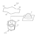
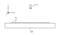
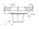
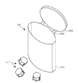
図1は、カプセルを示す斜視図である。
カプセルCは、図1に示すように、粉粒体Pを充填する容器C1と、この容器C1の開口部に貼り付けることによって、粉粒体Pを密封するフィルム状の蓋材C2とを備えている。
容器C1は、有底筒状に形成されるとともに、頂部から底部に向かうにしたがって僅かに縮径するように形成された断面六角形状の胴体C11と、頂部に形成されたフランジC12とを有している。
蓋材C2は、容器C1の開口部を覆う六角形状の基部C21と、この基部C21の対向する2辺のそれぞれに形成された矩形状の耳部C22とを有している。
FIG. 1 is a perspective view showing a capsule.
As shown in FIG. 1, the capsule C includes a container C1 that is filled with the powder and granules P, and a film-shaped lid member C2 that seals the powder and granules P by being attached to the opening of the container C1. ing.
The container C1 has a bottomed tubular shape, and has a body C11 having a hexagonal cross-section formed so as to be slightly reduced in diameter from the top to the bottom, and a flange C12 formed on the top. ing.
The lid member C2 has a hexagonal base C21 that covers the opening of the container C1 and rectangular ears C22 formed on each of two opposing sides of the base C21.

なお、本実施形態では、容器C1は、断面六角形状の胴体C11を有しているが、断面四角形状などの他の断面形状の胴体を有していてもよい。また、容器C1は、フランジC12を有しているが、これを有していなくてもよい。さらに、蓋材C2は、矩形状の2つの耳部C22を有しているが、1つ、または3つ以上の耳部を有していてもよく、耳部を有していなくてもよい。要するに、本発明では、容器および蓋材は、どのような形状であってもよい。 In addition, in this embodiment, the container C1 has a body C11 having a hexagonal cross section, but may have a body having another cross section such as a square cross section. Further, although the container C1 has the flange C12, it does not have to have this. Furthermore, although the lid member C2 has two rectangular ears C22, it may have one or three or more ears, or may not have ears. .. In short, in the present invention, the container and the lid member may have any shape.

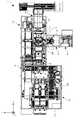
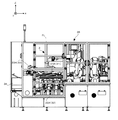
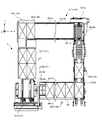
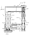
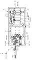
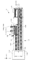
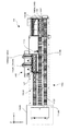
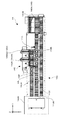
図2は、カプセルの製造装置を示す図である。具体的には、図2は、カプセルの製造装置1を鉛直上方側から見た模式図である。なお、図2では、鉛直上方向を+Z軸方向とし、このZ軸と直交する2軸をX,Y軸として説明する。以下の図面においても同様である。
カプセルの製造装置1は、図2に示すように、複数の容器C1を収容したメインパレットMPを所定方向(+X軸方向)に搬送することによって、複数の容器C1を搬送するメインコンベア2を備えている。
FIG. 2 is a diagram showing a capsule manufacturing apparatus. Specifically, FIG. 2 is a schematic view of the capsule manufacturing apparatus 1 viewed from the vertically upper side. In FIG. 2, the vertical upward direction is the +Z axis direction, and the two axes orthogonal to the Z axis are the X and Y axes. The same applies to the following drawings.
As shown in FIG. 2, the capsule manufacturing apparatus 1 includes a main conveyor 2 that conveys a plurality of containers C1 by conveying a main pallet MP containing a plurality of containers C1 in a predetermined direction (+X axis direction). ing.

また、カプセルの製造装置1は、容器供給装置3と、容器クリーニング装置4と、容器移載装置5と、充填装置6と、充填チェック装置7と、フィルム供給装置8と、フィルムダイカット装置9と、フィルム移載装置10と、シール装置11と、フィルム分離装置12と、スクラップ排出装置13と、カプセル仕分装置14とを備え、これらの装置は、メインコンベア2の上流側から下流側に向かって配設されている。
なお、メインコンベア2および各装置3〜14は、ガラス板を嵌め込まれたフレームFLにて密閉された領域の内部に収納されている。作業者は、メインコンベア2および各装置3〜14の近傍にそれぞれ配設された扉を開くことによって、メインコンベア2および各装置3〜14のメンテナンス等を実施できる。
Further, the capsule manufacturing apparatus 1 includes a container supply device 3, a container cleaning device 4, a container transfer device 5, a filling device 6, a filling check device 7, a film supply device 8, and a film die cutting device 9. , A film transfer device 10, a sealing device 11, a film separation device 12, a scrap discharge device 13, and a capsule sorting device 14, and these devices are arranged from the upstream side of the main conveyor 2 toward the downstream side. It is arranged.
The main conveyor 2 and each of the devices 3 to 14 are housed inside a region hermetically sealed by a frame FL in which a glass plate is fitted. The operator can perform maintenance and the like of the main conveyor 2 and the devices 3 to 14 by opening the doors provided near the main conveyor 2 and the devices 3 to 14, respectively.

容器供給装置3は、メインパレットMPと略同様の形状に形成されたダミーパレットDPに複数の容器C1を供給する。この容器供給装置3およびダミーパレットDPについては後に詳述する。
容器クリーニング装置4は、容器供給装置3にてダミーパレットDPに供給された複数の容器C1を清掃することによって、容器C1に付着している粉塵などの異物を除去する。この容器クリーニング装置4については後に詳述する。
容器移載装置5は、容器供給装置3にてダミーパレットDPに供給された複数の容器C1を移載してメインパレットMPに収容する。この容器移載装置5にて複数の容器C1を移載されたメインパレットMPは、メインコンベア2にて搬送される。
充填装置6は、メインコンベア2にて搬送されてきたメインパレットMPに収容された容器C1に粉粒体Pを充填する。
充填チェック装置7は、充填装置6にて容器C1に粉粒体Pが充填されたか否かを確認する。
The container supply device 3 supplies the plurality of containers C1 to the dummy pallet DP formed in a shape substantially similar to the main pallet MP. The container supply device 3 and the dummy pallet DP will be described in detail later.
The container cleaning device 4 removes foreign substances such as dust adhering to the container C1 by cleaning the plurality of containers C1 supplied to the dummy pallet DP by the container supply device 3. The container cleaning device 4 will be described in detail later.
The container transfer device 5 transfers the plurality of containers C1 supplied to the dummy pallet DP by the container supply device 3 and stores them in the main pallet MP. The main pallet MP to which the plurality of containers C1 have been transferred by the container transfer device 5 is conveyed by the main conveyor 2.
The filling device 6 fills the container C1 housed in the main pallet MP conveyed by the main conveyor 2 with the powder P.
The filling check device 7 confirms whether or not the container C1 is filled with the granular material P by the filling device 6.

フィルム供給装置8は、フィルムダイカット装置9に蓋材C2を切り出すためのフィルムを供給する。
フィルムダイカット装置9は、フィルム供給装置8にて供給されたフィルムに蓋材C2を切り出すためのミシン目を形成するとともに、このフィルムをメインパレットMPと対応する大きさに切断する。
フィルム移載装置10は、フィルムダイカット装置9にて切断されたフィルムをメインコンベア2にて搬送されてきたメインパレットMPに移載する。このとき、フィルム移載装置10は、フィルムに形成された蓋材C2の位置と、メインパレットMPに収容された容器C1の開口部の位置とを合せるようにしてフィルムを移載する。
The film supply device 8 supplies a film for cutting the lid member C2 to the film die cutting device 9.
The film die cutting device 9 forms perforations for cutting the lid material C2 on the film supplied by the film supply device 8 and cuts this film into a size corresponding to the main pallet MP.
The film transfer device 10 transfers the film cut by the film die cutting device 9 onto the main pallet MP conveyed by the main conveyor 2. At this time, the film transfer device 10 transfers the film by aligning the position of the lid member C2 formed on the film with the position of the opening of the container C1 accommodated in the main pallet MP.

シール装置11は、フィルム移載装置10にてメインパレットMPに移載されたフィルムに形成された蓋材C2と、メインパレットMPに収容された容器C1の開口部とをシールして接着することによって、カプセルCに粉粒体Pを密封する。
フィルム分離装置12は、フィルムに形成された蓋材C2と、メインパレットMPに収容された容器C1の開口部とをシール装置11にてシールして接着した後、フィルムから蓋材C2を分離する。
The sealing device 11 seals and adheres the lid member C2 formed on the film transferred to the main pallet MP by the film transfer device 10 and the opening of the container C1 accommodated in the main pallet MP. Then, the powder P is sealed in the capsule C.
The film separating device 12 separates the lid member C2 from the film after sealing and adhering the lid member C2 formed on the film and the opening of the container C1 accommodated in the main pallet MP with the sealing device 11. .

スクラップ排出装置13は、フィルム分離装置12にて蓋材C2を分離した後の残ったフィルム(スクラップ)をメインパレットMPから回収して排出する。
カプセル仕分装置14は、フィルム分離装置12にて蓋材C2を分離した後のカプセルCをメインパレットMPから取り出し、所定の個数ごとに仕分けてケースに収納する。
このように、カプセルの製造装置1は、複数個のカプセルCを一単位としてメインパレットMPごとに間欠的に製造している。
以下、カプセルの製造装置1を構成する各装置について順に説明する。
The scrap discharging device 13 collects and discharges the film (scrap) remaining after the cover material C2 is separated by the film separating device 12 from the main pallet MP.
The capsule sorting device 14 takes out the capsules C from which the lid material C2 has been separated by the film separating device 12 from the main pallet MP, sorts them into a predetermined number, and stores them in a case.
As described above, the capsule manufacturing apparatus 1 intermittently manufactures the plurality of capsules C as one unit for each main pallet MP.
Hereinafter, each device constituting the capsule manufacturing apparatus 1 will be described in order.

〔メインコンベア〕
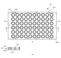
図3は、メインコンベアに用いられるメインパレットの上面図である。
メインコンベア2は、複数の容器C1を収容したメインパレットMPを所定方向(+X軸方向)に搬送することによって、複数の容器C1を搬送する。まず、このメインコンベア2に用いられるメインパレットMPについて説明する。
メインパレットMPは、図3に示すように、矩形板状に形成された金属製のパレットである。このメインパレットMPは、上下面を貫通して形成されるとともに、容器C1を上面側から挿入して収容する複数の断面六角形状の収容部MP1を有している。換言すれば、収容部MP1は、容器C1の胴体C11と同様の断面形状に形成された穴であり、1つの容器C1を内部に収容することができる。
[Main conveyor]
FIG. 3 is a top view of a main pallet used for the main conveyor.
The main conveyor 2 conveys the plurality of containers C1 by conveying the main pallet MP accommodating the plurality of containers C1 in a predetermined direction (+X axis direction). First, the main pallet MP used for the main conveyor 2 will be described.
As shown in FIG. 3, the main pallet MP is a metal pallet formed in a rectangular plate shape. The main pallet MP has a plurality of accommodating portions MP1 formed to penetrate through the upper and lower surfaces and having a hexagonal cross section for accommodating and accommodating the container C1 from the upper surface side. In other words, the accommodating portion MP1 is a hole formed in the same sectional shape as the body C11 of the container C1 and can accommodate one container C1 inside.

具体的には、メインパレットMPは、長手方向(行方向)に沿って等間隔に10個の収容部MP1を配列しているとともに、短手方向(列方向)に沿って等間隔に5個の収容部MP1を配列している。換言すれば、メインパレットMPは、格子点状に50個の収容部MP1を有している。
なお、本実施形態では、メインパレットMPは、格子点状に50個の収容部MP1を有しているが、50とは異なる2以上の個数の収容部を有していればよい。また、本実施形態では、収容部は、格子点状に配列されているが、格子点状に配列していなくてもよく、その並び方は規則性を有していなくてもよい。
Specifically, the main pallet MP has ten accommodation parts MP1 arranged at equal intervals along the longitudinal direction (row direction), and five accommodation parts MP1 at equal intervals along the lateral direction (column direction). The accommodating portions MP1 are arranged. In other words, the main pallet MP has 50 accommodating portions MP1 arranged in a grid.
In addition, in the present embodiment, the main pallet MP has 50 accommodation parts MP1 in a lattice shape, but it is sufficient that the main pallet MP has two or more accommodation parts different from 50. Further, in the present embodiment, the accommodating portions are arranged in a lattice point shape, but they may not be arranged in a lattice point shape, and the arrangement manner may not have regularity.

ここで、容器C1の胴体C11の外径は、収容部MP1の内径よりも僅かに小さく形成されている。また、容器C1のフランジC12の外径は、収容部MP1の内径よりも僅かに大きく形成されている。
したがって、メインパレットMPの収容部MP1の内部に容器C1を収容すると、フランジC12は収容部MP1の外部に突出し、胴体C11は収容部MP1の内部に収容される。換言すれば、容器C1は、頂部を鉛直上方側に位置させるとともに、底部を鉛直下方側に位置させた一定の姿勢を取るようにして収容部MP1に収容され、これとは逆の姿勢を取るようにして収容部MP1に収容されることはない。
そして、前述したように、容器C1は、有底筒状に形成されるとともに、頂部から底部に向かうにしたがって僅かに縮径するように形成された断面六角形状の胴体C11を有しているので、収容部MP1に入り込みやすくなっている。
Here, the outer diameter of the body C11 of the container C1 is formed to be slightly smaller than the inner diameter of the accommodation portion MP1. Further, the outer diameter of the flange C12 of the container C1 is formed to be slightly larger than the inner diameter of the accommodation portion MP1.
Therefore, when the container C1 is housed inside the housing part MP1 of the main pallet MP, the flange C12 projects outside the housing part MP1 and the body C11 is housed inside the housing part MP1. In other words, the container C1 is accommodated in the accommodating portion MP1 in such a manner that the top portion is located vertically above and the bottom portion is located vertically below, and the container C1 is placed in the opposite posture. Thus, it is not housed in the housing part MP1.
Then, as described above, the container C1 is formed in a cylindrical shape with a bottom, and has the body C11 having a hexagonal cross-section formed so as to be slightly reduced in diameter from the top to the bottom. , It is easy to enter the accommodation portion MP1.

また、メインパレットMPは、長手方向の端部のそれぞれに形成されるとともに、上方に向かって突出する2つの円柱状のピンMP2と、図3左下側および図3右上側の端部のそれぞれに上下面を貫通して形成された2つの断面円形の貫通孔MP3と、−X軸方向側の側面に貼り付けられた2つの円盤状のウレタンゴムMP4とを有している。これらの部位については後に詳述する。 Further, the main pallet MP is formed at each of the end portions in the longitudinal direction, and has two columnar pins MP2 protruding upward, and at each of the end portions on the lower left side of FIG. 3 and the upper right side of FIG. It has two through-holes MP3 having a circular cross section formed penetrating the upper and lower surfaces, and two disc-shaped urethane rubber MP4 attached to the side surface on the −X axis direction side. These parts will be described in detail later.

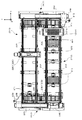
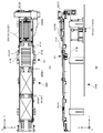
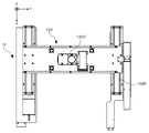
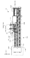
図4は、メインコンベアを示す図である。具体的には、図4は、メインコンベア2を鉛直上方側から見た模式図である。
メインコンベア2は、図4に示すように、複数の容器C1を収容したメインパレットMPを所定方向(+X軸方向)に搬送することによって、複数の容器C1を搬送する往路用コンベア21と、往路用コンベア21と平行に配設されるとともに、複数の容器C1を回収したメインパレットMPを所定方向と反対方向(−X軸方向)に搬送することによって、メインパレットMPを往路用コンベア21の上流側に搬送する復路用コンベア22とを備えている。
FIG. 4 is a diagram showing the main conveyor. Specifically, FIG. 4 is a schematic view of the main conveyor 2 viewed from the vertically upper side.
As shown in FIG. 4, the main conveyor 2 conveys the main pallet MP accommodating the plurality of containers C1 in a predetermined direction (+X-axis direction) to convey the plurality of containers C1 and the outward conveyer 21. The main pallet MP is arranged in parallel with the conveyor 21 and conveys the main pallet MP in which the plurality of containers C1 are collected in a direction opposite to the predetermined direction (-X axis direction), so that the main pallet MP is upstream of the forward conveyer 21. And a return conveyor 22 that conveys to the side.

往路用コンベア21は、メインパレットMPの長手方向の両端部にそれぞれ当接するように設けられた複数のローラ21Aと、各ローラ21Aを回転させるモータ21Bとを備えている。この往路用コンベア21は、モータ21Bにて各ローラ21Aを回転させることによって、各ローラ21Aに載置されたメインパレットMPを+X軸方向に搬送する。 The forward path conveyor 21 includes a plurality of rollers 21A provided so as to be in contact with both ends of the main pallet MP in the longitudinal direction, and a motor 21B for rotating each roller 21A. The forward path conveyor 21 conveys the main pallet MP placed on each roller 21A in the +X axis direction by rotating each roller 21A by the motor 21B.

復路用コンベア22は、メインパレットMPの長手方向の両端部にそれぞれ当接するように設けられた複数のローラ22Aと、各ローラ22Aを回転させるモータ22Bとを備えている。この復路用コンベア22は、モータ22Bにて各ローラ22Aを回転させることによって、各ローラ22Aに載置されたメインパレットMPを−X軸方向に搬送する。 The return conveyor 22 includes a plurality of rollers 22A provided so as to contact both ends of the main pallet MP in the longitudinal direction, and a motor 22B for rotating each roller 22A. The backward conveyer 22 conveys the main pallet MP placed on each roller 22A in the -X axis direction by rotating each roller 22A with a motor 22B.

また、復路用コンベア22は、メインパレットMPを搬送する途中に設けられるとともに、メインパレットMPを清掃するパレット清掃機構22Cを備えている。このパレット清掃機構22Cは、メインパレットMPを挟むようにしてメインパレットMPの鉛直上方側および鉛直下方側の2箇所にそれぞれ設けられたパレット清掃用吸引機22C1(鉛直上方側のパレット清掃用吸引機22C1のみ図示)と、各パレット清掃用吸引機22C1の内部に取り付けられるとともに、モータ(図示略)にて回転させられることによって、メインパレットMPの上面および下面に付着した粉粒体Pや異物などを擦り落とすブラシ(図示略)とを備えている。そして、パレット清掃機構22Cは、復路用コンベア22にて搬送されてきたメインパレットMPの上面および下面に付着した粉粒体Pや異物などをブラシにて擦り落とし、各パレット清掃用吸引機22C1にて吸引して除去することによって、メインパレットMPを清掃する。 The return conveyor 22 is provided on the way of transporting the main pallet MP and has a pallet cleaning mechanism 22C for cleaning the main pallet MP. The pallet cleaning mechanism 22C includes a pallet cleaning suction device 22C1 (only the pallet cleaning suction device 22C1 on the vertically upper side) provided at two positions on the vertically upper side and the vertically lower side of the main pallet MP so as to sandwich the main pallet MP. (Not shown) and the inside of each pallet cleaning suction device 22C1 and is rotated by a motor (not shown) to rub off the powder particles P and foreign matter attached to the upper and lower surfaces of the main pallet MP. And a brush (not shown) for dropping. Then, the pallet cleaning mechanism 22C scrapes off the powdery particles P, foreign matters, and the like adhering to the upper surface and the lower surface of the main pallet MP conveyed by the return path conveyor 22 with a brush, and then the pallet cleaning suction device 22C1. The main pallet MP is cleaned by suctioning and removing.

また、メインコンベア2は、復路用コンベア22にて往路用コンベア21の上流側に搬送されてきたメインパレットMPを往路用コンベア21に送り出す往路用送出機構23と、往路用コンベア21にて復路用コンベア22の上流側に搬送されてきたメインパレットMPを復路用コンベア22に送り出す復路用送出機構24とを備えている。 In addition, the main conveyor 2 includes a forward path delivery mechanism 23 that sends out the main pallet MP, which has been conveyed upstream of the forward path conveyor 21 by the backward path conveyor 22, to the forward path conveyor 21, and a forward path conveyor 21. A return path delivery mechanism 24 for sending out the main pallet MP conveyed to the upstream side of the conveyor 22 to the return path conveyor 22.

往路用送出機構23は、X軸まわりに回転自在に設けられるとともに、メインパレットMPの中央部に当接するように設けられた複数のローラ23Aと、メインパレットMPの+Y軸方向側の側面に当接する送出用プレート23Bと、送出用プレート23BをY軸方向に沿って移動させる移動機構23Cと、メインパレットMPを搬送する途中に設けられた容器検出手段23Dと、往路用送出機構23の終点位置に設けられた静電気除去手段23Eとを備えている。この往路用送出機構23は、移動機構23Cにて送出用プレート23Bを−Y軸方向に移動させることによって、各ローラ23Aに載置されたメインパレットMPを往路用コンベア21に送り出す。 The forward path delivery mechanism 23 is rotatably provided around the X-axis, and a plurality of rollers 23A provided so as to contact the central portion of the main pallet MP and the side surface of the main pallet MP on the +Y-axis direction side. The delivery plate 23B in contact, the moving mechanism 23C for moving the delivery plate 23B along the Y-axis direction, the container detection means 23D provided on the way of transporting the main pallet MP, and the end position of the forward delivery mechanism 23. And a static electricity removing unit 23E provided in. The forward path sending mechanism 23 sends the main pallet MP placed on each roller 23A to the outgoing path conveyor 21 by moving the sending plate 23B in the −Y axis direction by the moving mechanism 23C.

容器検出手段23Dは、メインパレットMPの短手方向に沿って設けられるとともに、メインパレットMPの収容部MP1に収容された容器C1の有無を検する5つのセンサ23D1を備えている。各センサ23D1は、メインパレットMPの収容部MP1に収容された容器C1の鉛直上方に配設されるとともに、メインパレットMPの収容部MP1に収容された各列の容器C1と対応する位置に配設されている。なお、本実施形態では、各センサ23D1は、透過型のレーザセンサを採用している。 The container detection means 23D is provided along the lateral direction of the main pallet MP and includes five sensors 23D1 for detecting the presence or absence of the container C1 stored in the storage portion MP1 of the main pallet MP. Each sensor 23D1 is arranged vertically above the container C1 accommodated in the accommodating portion MP1 of the main pallet MP, and arranged at a position corresponding to the container C1 in each row accommodated in the accommodating portion MP1 of the main pallet MP. It is set up. In the present embodiment, each sensor 23D1 employs a transmissive laser sensor.

静電気除去手段23Eは、往路用送出機構23にて往路用コンベア21に送り出されたメインパレットMPの鉛直上方に配設されるとともに、このメインパレットMPに収容された複数の容器C1の静電気を除去する。なお、本実施形態では、静電気除去手段23Eは、ブロアタイプの静電気除去装置を採用している。 The static electricity removing means 23E is disposed vertically above the main pallet MP sent to the forward path conveyor 21 by the forward path sending mechanism 23, and removes static electricity from the plurality of containers C1 accommodated in the main pallet MP. To do. In the present embodiment, the static electricity removing means 23E employs a blower type static electricity removing device.

復路用送出機構24は、X軸まわりに回転自在に設けられるとともに、メインパレットMPの中央部に当接するように設けられた複数のローラ24Aと、メインパレットMPの−Y軸方向側の側面に当接する送出用プレート24Bと、送出用プレート24BをY軸方向に沿って移動させる移動機構24Cとを備えている。この復路用送出機構24は、移動機構24Cにて送出用プレート24Bを+Y軸方向に移動させることによって、各ローラ24Aに載置されたメインパレットMPを復路用コンベア22に送り出す。 The return path delivery mechanism 24 is rotatably provided around the X axis, and has a plurality of rollers 24A provided so as to abut the center of the main pallet MP and a side surface of the main pallet MP on the −Y axis direction side. The delivery plate 24B that abuts and a moving mechanism 24C that moves the delivery plate 24B along the Y-axis direction are provided. The return path delivery mechanism 24 sends the main pallet MP mounted on each roller 24A to the return path conveyor 22 by moving the delivery plate 24B in the +Y axis direction by the moving mechanism 24C.

したがって、メインコンベア2は、メインパレットMPを往路用コンベア21にて+X軸方向に搬送した後、復路用送出機構24にて復路用コンベア22に送り出し、復路用コンベア22にて−X軸方向に搬送した後、往路用送出機構23にて往路用コンベア21に再び送り出すので、メインパレットMPをZ軸まわりに回転させるように巡回させて搬送する。 Therefore, the main conveyor 2 conveys the main pallet MP in the +X axis direction by the forward path conveyor 21, then sends it out to the backward path conveyor 22 by the backward path sending mechanism 24, and in the −X axis direction by the backward path conveyor 22. After the transport, the transport mechanism 23 for the outward route sends the sheet again to the conveyor 21 for the outward route, so that the main pallet MP is circulated so as to rotate around the Z axis and is conveyed.

〔容器供給装置〕
本発明の容器供給装置3は、ダミーパレットDP(パレット)の収容部に容器C1を確実に供給することができ、製造効率を向上させることができる。
以下、本発明の一実施形態に係る容器供給装置3について説明する。
[Container supply device]
The container supply device 3 of the present invention can reliably supply the container C1 to the accommodation portion of the dummy pallet DP (pallet), and can improve the manufacturing efficiency.
Hereinafter, the container supply device 3 according to an embodiment of the present invention will be described.

図5は、本発明の一実施形態に係る容器供給装置に用いられるダミーパレットの上面図および断面図である。具体的には、図5(A)は、ダミーパレットDPの上面図であり、図5(B)は、ダミーパレットDPを長手方向に沿って切断したAA断面図である。
容器供給装置3は、ダミーパレットDPに容器C1を供給する装置である。まず、この容器供給装置3に用いられるダミーパレットDPについて説明する。
ダミーパレットDPは、図5に示すように、四隅を面取りした矩形板状に形成された樹脂製のベースDPBと、ベースDPBの上面にネジ留めされて取り付けられたステンレス鋼製のプレートDPLとを有している。また、このプレートDPLの上面には、表面を滑らかにするための表面処理を施している。したがって、本実施形態では、ダミーパレットDPの上面には、表面を滑らかにするための表面処理が施されている。
FIG. 5 is a top view and a cross-sectional view of a dummy pallet used in the container supply device according to the embodiment of the present invention. Specifically, FIG. 5(A) is a top view of the dummy pallet DP, and FIG. 5(B) is an AA sectional view of the dummy pallet DP cut along the longitudinal direction.
The container supply device 3 is a device that supplies the container C1 to the dummy pallet DP. First, the dummy pallet DP used in the container supply device 3 will be described.
As shown in FIG. 5, the dummy pallet DP includes a resin base DPB formed in a rectangular plate shape with chamfered four corners, and a stainless steel plate DPL screwed and attached to the upper surface of the base DPB. Have Further, the upper surface of the plate DPL is subjected to surface treatment for smoothing the surface. Therefore, in the present embodiment, the upper surface of the dummy pallet DP is subjected to surface treatment for smoothing the surface.

ここで、表面を滑らかにするための表面処理としては、例えば、ニダックス(登録商標)処理を採用することができるが、表面を滑らかにするための表面処理であれば、これ以外の処理を採用してもよい。
なお、本実施形態では、ダミーパレットDPの上面には、表面を滑らかにするための表面処理が施されているが、表面処理が施されていなくてもよい。
Here, as the surface treatment for smoothing the surface, for example, NIDAX (registered trademark) treatment can be adopted, but if the surface treatment for smoothing the surface, other treatments are adopted. You may.
In addition, in the present embodiment, the upper surface of the dummy pallet DP is subjected to the surface treatment for smoothing the surface, but the surface treatment may not be performed.

ベースDPBは、上下面を貫通して形成されるとともに、容器C1を上面側から挿入して収容する複数の断面六角形状の収容部DP1を有している。換言すれば、収容部DP1は、容器C1の胴体C11と同様の断面形状に形成された穴であり、1つの容器C1を内部に収容することができる。 The base DPB has a plurality of accommodating portions DP1 that are formed so as to penetrate through the upper and lower surfaces and that accommodate the container C1 by inserting the container C1 from the upper surface side. In other words, the accommodating portion DP1 is a hole formed in the same sectional shape as the body C11 of the container C1 and can accommodate one container C1 therein.

具体的には、ベースDPBは、長手方向(行方向)に沿って等間隔に10個の収容部DP1を配列しているとともに、短手方向(列方向)に沿って等間隔に6個の収容部DP1を配列している。換言すれば、ベースDPBは、格子点状に60個の収容部DP1を有している。
なお、本実施形態では、ベースDPBは、格子点状に60個の収容部DP1を有しているが、60とは異なる2以上の個数の収容部を有していればよい。また、本実施形態では、収容部は、格子点状に配列されているが、格子点状に配列していなくてもよく、その並び方は規則性を有していなくてもよい。
Specifically, the base DPB has ten accommodating portions DP1 arranged at equal intervals along the longitudinal direction (row direction), and six accommodating portions DP1 at equal intervals along the lateral direction (column direction). The accommodating portions DP1 are arranged. In other words, the base DPB has 60 accommodating portions DP1 arranged in a lattice shape.
In addition, in the present embodiment, the base DPB has 60 accommodating portions DP1 in a lattice shape, but it may have two or more accommodating portions different from 60. Further, in the present embodiment, the accommodating portions are arranged in a lattice point shape, but they may not be arranged in a lattice point shape, and the arrangement manner may not have regularity.

ここで、容器C1の胴体C11の外径は、収容部DP1の内径よりも僅かに小さく形成されている。また、容器C1のフランジC12の外径は、収容部DP1の内径よりも僅かに大きく形成されている。
したがって、ベースDPBの収容部DP1の内部に容器C1を収容すると、フランジC12は収容部DP1の外部に突出し、胴体C11は収容部DP1の内部に収容される。換言すれば、容器C1は、頂部を鉛直上方側に位置させるとともに、底部を鉛直下方側に位置させた一定の姿勢を取るようにして収容部DP1に収容され、これとは逆の姿勢を取るようにして収容部DP1に収容されることはない。
また、前述したように、容器C1は、有底筒状に形成されるとともに、頂部から底部に向かうにしたがって僅かに縮径するように形成された断面六角形状の胴体C11を有しているので、収容部DP1に入り込みやすくなっている。
Here, the outer diameter of the body C11 of the container C1 is formed to be slightly smaller than the inner diameter of the accommodation portion DP1. Further, the outer diameter of the flange C12 of the container C1 is formed to be slightly larger than the inner diameter of the accommodation portion DP1.
Therefore, when the container C1 is housed inside the housing portion DP1 of the base DPB, the flange C12 projects outside the housing portion DP1 and the body C11 is housed inside the housing portion DP1. In other words, the container C1 is accommodated in the accommodating portion DP1 in such a manner that the top portion is located vertically above and the bottom portion is located vertically below, and the container C1 is placed in the opposite posture. Thus, it is not housed in the housing part DP1.
Further, as described above, the container C1 is formed in the shape of a cylinder with a bottom, and has the body C11 having a hexagonal cross-section formed so as to be slightly reduced in diameter from the top to the bottom. , It is easy to enter the accommodation portion DP1.

プレートDPLは、ベースDPBの収容部DP1と対応する位置にそれぞれ形成された断面円形状の貫通孔DP2を有している。各貫通孔DP2は、ダミーパレットDPの下面側から上面側に向かうにしたがって拡径するように形成されている。
したがって、ダミーパレットDPの収容部DP1は、貫通孔DP2を備え、この貫通孔DP2は、ダミーパレットDPの上面側に向かうにしたがって拡開する拡開部として機能する。
なお、本実施形態では、ダミーパレットDPの収容部DP1は、貫通孔DP2を備え、この貫通孔DP2は、ダミーパレットDPの下面側から上面側に向かうにしたがって拡径するように形成されているが、拡径するように形成されていなくてもよい。
The plate DPL has through holes DP2 having a circular cross section formed at positions corresponding to the housing portion DP1 of the base DPB. Each through hole DP2 is formed so that the diameter increases from the lower surface side of the dummy pallet DP toward the upper surface side.
Therefore, the accommodating portion DP1 of the dummy pallet DP includes the through hole DP2, and the through hole DP2 functions as an expanding portion that expands toward the upper surface side of the dummy pallet DP.
In addition, in the present embodiment, the accommodation portion DP1 of the dummy pallet DP is provided with the through hole DP2, and the through hole DP2 is formed so that the diameter increases from the lower surface side to the upper surface side of the dummy pallet DP. However, it does not have to be formed so as to increase the diameter.

また、ダミーパレットDPは、長手方向の端部のそれぞれに形成されるとともに、ベースDPBおよびプレートDPLの上下面を貫通する2つの断面円形状の貫通孔DP3を有している。これらの部位については後に詳述する。 Further, the dummy pallet DP has two through-holes DP3 having circular cross-sections which are formed at the respective ends in the longitudinal direction and penetrate the upper and lower surfaces of the base DPB and the plate DPL. These parts will be described in detail later.

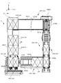
図6は、ダミーパレットに容器を供給する容器供給装置の上面図である。具体的には、図6は、+Z軸方向側から容器供給装置3を見た図である。
容器供給装置3は、図6に示すように、X軸方向に沿って互いに平行となるように配設されるとともに、ダミーパレットDPの上面に形成された複数の収容部DP1のそれぞれに容器C1を供給する2つの容器供給機構3A,3Bと、容器供給機構3A,3Bを囲むように配設されるとともに、ダミーパレットDPを容器供給機構3A,3Bに対して搬入・搬出するパレット搬送手段36と、容器供給機構3A,3Bにて容器C1を供給できなかった収容部DP1に容器C1を補充する容器補充機構37とを備えている。
FIG. 6 is a top view of a container supply device that supplies a container to a dummy pallet. Specifically, FIG. 6 is a view of the container supply device 3 viewed from the +Z axis direction side.
As shown in FIG. 6, the container supply device 3 is arranged so as to be parallel to each other along the X-axis direction, and the container C1 is provided in each of the plurality of accommodation parts DP1 formed on the upper surface of the dummy pallet DP. Pallet conveying means 36 for arranging the two container supplying mechanisms 3A, 3B for supplying the container and the container supplying mechanisms 3A, 3B and for carrying the dummy pallet DP in and out of the container supplying mechanisms 3A, 3B. And a container replenishing mechanism 37 for replenishing the container C1 to the accommodation portion DP1 where the container supply mechanism 3A, 3B could not supply the container C1.

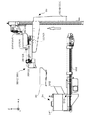
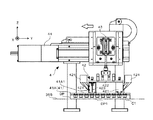
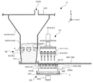
図7は、容器供給装置の側面図である。具体的には、図7は、−Y軸方向側から容器供給装置3を見た図である。
容器供給機構3A,3Bは、同一の構成を備え、図7に示すように、ダミーパレットDPを配置するための容器供給用配置台31と、この容器供給用配置台31を振動させることによって、ダミーパレットDPを振動させるパレット振動手段としての小型電磁フィーダ32と、容器供給用配置台31(ダミーパレットDPの配置位置)の上方に配設されるとともに、複数の容器C1を保持する容器供給用ホッパー33とを備えている。
FIG. 7 is a side view of the container supply device. Specifically, FIG. 7 is a view of the container supply device 3 viewed from the −Y axis direction side.
The container supply mechanisms 3A and 3B have the same structure, and as shown in FIG. 7, by vibrating the container supply placement table 31 for placing the dummy pallet DP and the container supply placement table 31. A small electromagnetic feeder 32 as a pallet vibrating means for vibrating the dummy pallet DP, and a container supply unit arranged above the container supply disposition table 31 (arrangement position of the dummy pallet DP) and for holding a plurality of containers C1. And a hopper 33.

なお、以下の説明では、容器供給機構3Aの容器供給用配置台31を容器供給用配置台31Aとし、小型電磁フィーダ32を小型電磁フィーダ32Aとし、容器供給用ホッパー33を容器供給用ホッパー33Aとする。また、容器供給機構3Bの容器供給用配置台31を容器供給用配置台31Bとし、小型電磁フィーダ32を小型電磁フィーダ32Bとし、容器供給用ホッパー33を容器供給用ホッパー33Bとする。 In the following description, the container supply arrangement table 31 of the container supply mechanism 3A will be referred to as a container supply arrangement table 31A, the small electromagnetic feeder 32 will be referred to as a small electromagnetic feeder 32A, and the container supply hopper 33 will be referred to as a container supply hopper 33A. To do. Further, the container supply arrangement table 31 of the container supply mechanism 3B is a container supply arrangement table 31B, the small electromagnetic feeder 32 is a small electromagnetic feeder 32B, and the container supply hopper 33 is a container supply hopper 33B.

また、容器供給機構3A,3Bは、容器供給用ホッパー33の下方に設けられるとともに、複数の容器C1を貯留する貯留手段としての容器貯留槽34と、容器貯留槽34に貯留された複数の容器C1を搬送することによって、容器供給用ホッパー33に保持させる容器搬送手段35とを備えている。
なお、本実施形態では、パレット振動手段として小型電磁フィーダ32を採用しているが、電磁式とは異なる他の方式の振動発生器を採用してもよい。要するに、本発明では、パレット振動手段は、ダミーパレットを振動させることができればよい。
Further, the container supply mechanisms 3A and 3B are provided below the container supply hopper 33, and are a container storage tank 34 as storage means for storing a plurality of containers C1 and a plurality of containers stored in the container storage tank 34. It is provided with a container carrying means 35 for carrying the C1 and holding it in the container supply hopper 33.
In the present embodiment, the small electromagnetic feeder 32 is used as the pallet vibrating means, but a vibration generator of another method different from the electromagnetic type may be adopted. In short, in the present invention, the pallet vibrating means only needs to be able to vibrate the dummy pallet.

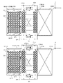
図8は、容器供給用ホッパーの近傍を拡大した側面図である。図9は、容器供給用ホッパーの近傍を拡大した上面図である。具体的には、図8は、−Y軸方向側から容器供給用ホッパー33の近傍を拡大して見た図であり、図9は、+Z軸方向側から容器供給用ホッパー33の近傍を拡大して見た図である。
容器供給用配置台31は、図8に示すように、容器貯留槽34側(紙面左側)に向かうにしたがって下降するように傾斜し、2枚のダミーパレットDPを短手方向に沿って配置する。
FIG. 8 is an enlarged side view of the vicinity of the container supply hopper. FIG. 9 is an enlarged top view of the vicinity of the container supply hopper. Specifically, FIG. 8 is an enlarged view of the vicinity of the container supply hopper 33 from the −Y axis direction side, and FIG. 9 is an enlarged view of the vicinity of the container supply hopper 33 from the +Z axis direction side. It is the figure seen.
As shown in FIG. 8, the container supply arranging table 31 is inclined so as to descend toward the container storage tank 34 side (the left side in the drawing), and two dummy pallets DP are arranged along the lateral direction. ..

具体的には、各ダミーパレットDPは、紙面表裏方向を長手方向とし、紙面左右方向を短手方向として容器供給用配置台31に配置される。
なお、本実施形態では、容器供給用配置台31は、2枚のダミーパレットDPを配置するように構成されているが、1枚のダミーパレットDPを配置するように構成されていてもよく、3枚以上の複数のダミーパレットDPを配置するように構成されていてもよい。
Specifically, each dummy pallet DP is arranged on the container supply arranging table 31 with the front-back direction of the paper being the longitudinal direction and the left-right direction of the paper being the lateral direction.
In addition, in the present embodiment, the container supply arranging table 31 is configured to dispose two dummy pallets DP, but it may be configured to dispose one dummy pallet DP. A plurality of dummy pallets DP of three or more may be arranged.

ここで、容器供給用配置台31Aおよび容器供給用配置台31Bは、図9に示すように、Y軸方向に沿って隣接して設けられている。換言すれば、第1の領域としての容器供給用配置台31Aに配置されたダミーパレットDPと、第2の領域としての容器供給用配置台31Bに配置されたダミーパレットDPとは、容器供給用配置台31Aおよび容器供給用配置台31Bの隣接方向に沿って隣接して配置されている。
なお、本実施形態では、隣接とは、2つの部材が隣り合う状態を言うものとし、2つの部材が当接していない状態を含むものとする。また、隣接方向とは、2つの部材が隣り合う方向を言うものとする。したがって、容器供給用配置台31Aおよび容器供給用配置台31Bの隣接方向はY軸方向となる。
Here, the container supply arranging table 31A and the container supply arranging table 31B are provided adjacent to each other along the Y-axis direction, as shown in FIG. In other words, the dummy pallet DP arranged on the container supply arrangement table 31A as the first area and the dummy pallet DP arranged on the container supply arrangement table 31B as the second area are used for container supply. The placement table 31A and the container supply placement table 31B are arranged adjacent to each other along the adjoining direction.
In the present embodiment, “adjacent” means a state in which two members are adjacent to each other, and includes a state in which the two members are not in contact with each other. Further, the adjacent direction means a direction in which two members are adjacent to each other. Therefore, the adjoining direction of the container supply disposition base 31A and the container supply disposition base 31B is the Y-axis direction.

また、本実施形態では、容器供給用ホッパー33Aは、容器供給用配置台31Aの上方に配設されるとともに、複数の容器C1を保持する第1の保持手段として機能する。また、本実施形態では、容器供給用ホッパー33Bは、容器供給用配置台31Bの上方に配設されるとともに、複数の容器C1を保持する第2の保持手段として機能する。 Further, in the present embodiment, the container supply hopper 33A is arranged above the container supply disposition table 31A and functions as a first holding unit that holds the plurality of containers C1. Further, in the present embodiment, the container supply hopper 33B is arranged above the container supply disposition table 31B and functions as a second holding unit that holds the plurality of containers C1.

また、容器供給装置3は、容器供給用配置台31Aに配置されたダミーパレットDPと、容器供給用配置台31Bに配置されたダミーパレットDPとの間に昇降自在に設けられることによって、複数の容器C1の移動を規制する規制手段としての仕切り板3Cを備えている。
仕切り板3Cは、ダミーパレットDPの上面に形成された複数の収容部DP1のそれぞれに容器C1を供給するときに下降し、容器供給用配置台31Aおよび容器供給用配置台31Bのそれぞれに配置されたダミーパレットDPの端部に当接して複数の容器C1の移動を規制する。また、仕切り板3Cは、ダミーパレットDPを容器供給機構3A,3Bに対して搬入・搬出するときに上昇し、容器供給用配置台31Aおよび容器供給用配置台31Bのそれぞれに配置されたダミーパレットDPの端部から離間する。
Further, the container supply device 3 is provided so as to be vertically movable between the dummy pallet DP arranged on the container supply arrangement table 31A and the dummy pallet DP arranged on the container supply arrangement table 31B. A partition plate 3C is provided as a regulation unit that regulates the movement of the container C1.
The partition plate 3C descends when the container C1 is supplied to each of the plurality of accommodating portions DP1 formed on the upper surface of the dummy pallet DP, and is arranged on each of the container supply disposition table 31A and the container supply disposition table 31B. The dummy pallet DP is brought into contact with the ends of the dummy pallet DP to restrict the movement of the plurality of containers C1. Further, the partition plate 3C rises when the dummy pallet DP is carried in and out of the container supply mechanisms 3A and 3B, and is placed on each of the container supply disposition base 31A and the container supply disposition base 31B. Separate from the end of the DP.

小型電磁フィーダ32は、図8に示すように、容器供給用配置台31の下方に配設されるとともに、容器供給用配置台31に配置された2枚のダミーパレットDPを振動させる。
容器供給用ホッパー33は、容器供給用配置台31に配置されたダミーパレットDPの短手方向と平行に配設されるとともに、容器供給用配置台31の傾斜と同様に傾斜して容器供給用配置台31の上方に配設されたレール部材33Rに取り付けられている。この容器供給用ホッパー33は、複数の容器C1を容器供給用配置台31に配置されたダミーパレットDPに向かって落下させる。
As shown in FIG. 8, the small electromagnetic feeder 32 is disposed below the container supply placement table 31 and vibrates the two dummy pallets DP placed on the container supply placement table 31.
The container supply hopper 33 is arranged in parallel with the lateral direction of the dummy pallet DP arranged on the container supply arrangement table 31, and is inclined similarly to the inclination of the container supply arrangement table 31 for container supply. It is attached to a rail member 33R arranged above the arrangement table 31. The container supply hopper 33 drops the plurality of containers C1 toward the dummy pallet DP arranged on the container supply arrangement table 31.

レール部材33Rは、図8および図9に示すように、容器供給用配置台31Aおよび容器供給用配置台31Bのそれぞれに配置された2枚のダミーパレットDPの長手方向の両側にそれぞれ設けられている。また、レール部材33Rは、上端部(紙面右側端部)に取り付けられるとともに、容器供給用配置台31に配置されたダミーパレットDPの上面に沿って容器貯留槽34側に空気を吐出するコンプレッサ33Cを備えている。 As shown in FIGS. 8 and 9, the rail members 33R are provided on both sides in the longitudinal direction of the two dummy pallets DP respectively arranged on the container supply arrangement table 31A and the container supply arrangement table 31B. There is. Further, the rail member 33R is attached to the upper end portion (the right end portion on the paper surface), and a compressor 33C that discharges air to the container storage tank 34 side along the upper surface of the dummy pallet DP arranged on the container supply placement table 31. Is equipped with.

コンプレッサ33Cは、図9に示すように、容器供給用配置台31Aに配置されたダミーパレットDPの上面に沿って容器貯留槽34側(紙面左側)に空気を吐出することによって、複数の容器C1を容器貯留槽34に落下させる第1の空気吐出部としてのコンプレッサ33CAと、容器供給用配置台31Bに配置されたダミーパレットDPの上面に沿って容器貯留槽34側(紙面左側)に空気を吐出することによって、複数の容器C1を容器貯留槽34に落下させる第2の空気吐出部としてのコンプレッサ33CBとを備えている。ここで、コンプレッサ33CBにて吐出される空気は、コンプレッサ33CAにて吐出される空気よりも弱くなるように設定されている。 As shown in FIG. 9, the compressor 33C discharges air toward the container storage tank 34 side (the left side of the drawing) along the upper surface of the dummy pallet DP arranged on the container supply placement table 31A, so that the plurality of containers C1 are discharged. The air is blown to the container storage tank 34 side (left side of the drawing) along the upper surface of the compressor 33CA as a first air discharger for dropping the air into the container storage tank 34 and the dummy pallet DP arranged on the container supply placement table 31B. The compressor 33CB is provided as a second air discharge unit that discharges the plurality of containers C1 into the container storage tank 34. Here, the air discharged from the compressor 33CB is set to be weaker than the air discharged from the compressor 33CA.

コンプレッサ33CAおよびコンプレッサ33CBは、ダミーパレットDPの上面に沿って容器貯留槽34側に空気を吐出するように分岐した4つの吐出口33Dを有し、各吐出口33Dから吐出される空気の強さは、それぞれ調整可能に構成されている。
なお、本実施形態では、コンプレッサ33CAおよびコンプレッサ33CBは、4つの吐出口33Dを有しているが、これとは異なる数の吐出口を有していてもよい。また、本実施形態では、各吐出口33Dから吐出される空気の強さは、それぞれ調整可能に構成されているが、調整可能に構成されていなくてもよい。
The compressor 33CA and the compressor 33CB have four discharge ports 33D branched along the upper surface of the dummy pallet DP so as to discharge air to the container storage tank 34 side, and the strength of the air discharged from each discharge port 33D. Are each adjustable.
In the present embodiment, the compressor 33CA and the compressor 33CB have four discharge ports 33D, but may have a different number of discharge ports. Further, in the present embodiment, the strength of the air discharged from each discharge port 33D is configured to be adjustable, but it may not be configured to be adjustable.

図10は、容器供給用ホッパーを更に拡大して見た図である。
容器供給用ホッパー33は、図10に示すように、レール部材33Rに沿って進退自在に設けられたスライダ331と、スライダ331に取り付けられるとともに、複数の容器C1を保持する本体部332と、本体部332に取り付けられるガイド部材333とを備えている。
FIG. 10 is a further enlarged view of the container supply hopper.
As shown in FIG. 10, the container supply hopper 33 includes a slider 331 that is provided so as to be movable back and forth along a rail member 33R, a main body portion 332 that is attached to the slider 331 and holds a plurality of containers C1, and a main body. And a guide member 333 attached to the portion 332.

スライダ331は、レール部材33Rの上面を転動する車輪(図示略)を備え、その内部に設けられたモータ(図示略)の駆動力によって車輪を回転させてレール部材33Rに沿って移動し、本体部332は、このスライダ331の移動に伴ってレール部材33Rに沿って移動する。したがって、レール部材33Rおよびスライダ331は、容器供給用ホッパー33を所定方向(ダミーパレットDPの短手方向)に沿って移動させる容器供給用移動手段として機能する。
なお、本実施形態では、容器供給装置3は、容器供給用移動手段を備えているが、これを備えていなくてもよい。
The slider 331 includes wheels (not shown) rolling on the upper surface of the rail member 33R, and the wheels are rotated by the driving force of a motor (not shown) provided therein to move along the rail member 33R. The main body 332 moves along the rail member 33R with the movement of the slider 331. Therefore, the rail member 33R and the slider 331 function as a container supply moving unit that moves the container supply hopper 33 along a predetermined direction (short direction of the dummy pallet DP).
In addition, in the present embodiment, the container supply device 3 includes a container supply moving unit, but it does not have to include this.

本体部332は、底面を構成するホッパーコンベア332Aと、本体部332の紙面右側の側面を除く3つの側面を構成するカバー332Bとを備え、ホッパーコンベア332Aおよびカバー332Bにて形成される空間内に複数の容器C1を保持する。
ホッパーコンベア332Aは、本体部332に取り付けられたモータ332A1の駆動力によって搬送路を本体部332の上流側(紙面左側)から下流側(紙面右側)に向かって移動させる。これによって、本体部332に収容された複数の容器C1は、本体部332の上流側から下流側に向かって移動することになる。
ここで、カバー332Bは、本体部332の下流側の側面を構成していないので、ホッパーコンベア332Aの搬送路を本体部332の上流側から下流側に向かって移動させると、複数の容器C1は、ホッパーコンベア332Aにて搬送された後、本体部332の下流側から落下していくことになる。
The main body portion 332 includes a hopper conveyor 332A forming a bottom surface and a cover 332B forming three side surfaces except the side surface on the right side of the paper surface of the main body portion 332, and is provided in a space formed by the hopper conveyor 332A and the cover 332B. Hold a plurality of containers C1.
The hopper conveyor 332A moves the conveyance path from the upstream side (left side of the drawing) of the main body 332 to the downstream side (right side of the drawing) by the driving force of the motor 332A1 attached to the main body 332. As a result, the plurality of containers C1 housed in the main body 332 move from the upstream side to the downstream side of the main body 332.
Here, since the cover 332B does not form a side surface on the downstream side of the main body 332, when the transport path of the hopper conveyor 332A is moved from the upstream side of the main body 332 toward the downstream side, the plurality of containers C1 After being conveyed by the hopper conveyor 332A, it will fall from the downstream side of the main body portion 332.

ガイド部材333は、本体部332に紙面表裏方向の軸を中心として回動自在に取り付けられるとともに、本体部332に設けられたシリンダ(図示略)の駆動力によって回動する。具体的には、ガイド部材333は、先端を上方に位置させた容器保持位置(図中二点鎖線)と、先端を下方に位置させたガイド位置(図中実線)との2つの位置のいずれかに回動して停止する。
なお、本実施形態では、容器供給用ホッパー33は、ガイド部材333を備えているが、これを備えていなくてもよい。要するに、本発明では、保持手段は、複数の容器をダミーパレットの上面に向かって供給させることができればよい。
The guide member 333 is rotatably attached to the main body 332 about an axis in the front-back direction of the paper surface, and is rotated by a driving force of a cylinder (not shown) provided in the main body 332. Specifically, the guide member 333 has either of two positions, a container holding position (the two-dot chain line in the figure) whose tip is located above and a guide position (the solid line in the figure) whose tip is located below. Turn to the crab and stop.
In addition, in this embodiment, the container supply hopper 33 includes the guide member 333, but the guide member 333 may not be provided. In short, in the present invention, the holding means only needs to be able to supply a plurality of containers toward the upper surface of the dummy pallet.

容器保持位置では、ガイド部材333は、先端側に向かうにしたがって上昇するように傾斜しているので、ホッパーコンベア332Aおよびカバー332Bと協働することによって有底筒状の空間を形成し、複数の容器C1を本体部332の下端側から落下させないようにする。換言すれば、ガイド部材333を容器保持位置に回動して停止させた状態では、ガイド部材333は、本体部332の下流側の側面を構成する。
ガイド位置では、ガイド部材333は、先端側に向かうにしたがって下降するように傾斜しているので、複数の容器C1は、ホッパーコンベア332Aにて搬送された後、ガイド部材333の上面を滑って本体部332の下流側から落下していくことになる。
At the container holding position, since the guide member 333 is inclined so as to rise toward the tip side, a bottomed cylindrical space is formed by cooperating with the hopper conveyor 332A and the cover 332B, and a plurality of The container C1 is prevented from falling from the lower end side of the main body 332. In other words, in the state where the guide member 333 is rotated to the container holding position and stopped, the guide member 333 constitutes the downstream side surface of the main body portion 332.
At the guide position, since the guide member 333 is inclined so as to descend toward the tip side, the plurality of containers C1 are transported by the hopper conveyor 332A and then slide on the upper surface of the guide member 333 to slide on the main body. It will fall from the downstream side of the portion 332.

なお、本実施形態では、ガイド部材333は、先端を上方に位置させた容器保持位置と、先端を下方に位置させたガイド位置との2つの位置のいずれかに回動して停止することができるように構成されているが、回動することができるように構成されていなくてもよい。この場合には、ガイド部材333は、ガイド位置に固定されていればよい。 Note that in the present embodiment, the guide member 333 can rotate and stop at either of two positions, a container holding position with its tip positioned above and a guide position with its tip positioned below. Although it is configured to be able to rotate, it may not be configured to be able to rotate. In this case, the guide member 333 may be fixed at the guide position.

図11は、ダミーパレットの収容部と、ガイド部材との関係を示す図である。具体的には、図11(A)は、ダミーパレットDPおよびガイド部材333を上方側から見た図であり、図11(B)は、図11(A)の紙面左右方向に沿ってガイド部材333を切断した断面を示す図である。また、図11(A)は、ガイド部材333をガイド位置に回動して停止させた状態を示す図である。
ガイド部材333は、図10および図11に示すように、本体部332に取り付けられた基端部からダミーパレットDP側の先端部に向かうにしたがって下降するように傾斜するレール状に形成された10個のレール部333Aを有し、各レール部333Aを一体的に形成して1つの部材としている。
FIG. 11 is a view showing the relationship between the accommodating portion of the dummy pallet and the guide member. Specifically, FIG. 11A is a view of the dummy pallet DP and the guide member 333 viewed from the upper side, and FIG. 11B is a guide member along the left-right direction of the paper surface of FIG. 11A. It is a figure which shows the cross section which cut|disconnected 333. FIG. 11A is a diagram showing a state in which the guide member 333 is rotated to the guide position and stopped.
As shown in FIGS. 10 and 11, the guide member 333 is formed in a rail shape 10 that is inclined so as to descend from the base end portion attached to the main body portion 332 toward the tip end portion on the dummy pallet DP side. It has individual rail portions 333A, and each rail portion 333A is integrally formed into one member.

各レール部333Aは、ダミーパレットDPの長手方向に沿って等間隔に配列された10個の収容部DP1と対応させて設けられている。また、各レール部333Aは、ダミーパレットDPの各収容部DP1の中心に向かって容器C1を滑らせて案内するV字状の溝部333A1を有している。具体的には、各レール部333Aは、ダミーパレットDPの短手方向と平行な方向に沿って設けられるとともに、その溝部333A1は、その最深部を収容部DP1の中心の鉛直上方に位置させるように形成されている(図中一点鎖線)。したがって、ガイド部材333は、ダミーパレットDPの収容部DP1の中心に向かって容器C1を落下させるようにガイドする。 Each rail portion 333A is provided so as to correspond to the ten accommodating portions DP1 arranged at equal intervals along the longitudinal direction of the dummy pallet DP. In addition, each rail portion 333A has a V-shaped groove portion 333A1 that slides and guides the container C1 toward the center of each accommodation portion DP1 of the dummy pallet DP. Specifically, each rail portion 333A is provided along a direction parallel to the lateral direction of the dummy pallet DP, and the groove portion 333A1 has its deepest portion positioned vertically above the center of the accommodation portion DP1. Is formed on the surface (dashed line in the figure). Therefore, the guide member 333 guides the container C1 to drop toward the center of the accommodation portion DP1 of the dummy pallet DP.

なお、本実施形態では、ガイド部材333は、本体部332に取り付けられた基端部からダミーパレットDP側の先端部に向かうにしたがって下降するように傾斜するレール状に形成されるとともに、ダミーパレットDPの各収容部DP1の中心に向かって容器C1を滑らせて案内するV字状の溝部333A1を有しているが、例えば、トンネル状などの他の形状に形成されていてもよい。要するに、ガイド部材は、ダミーパレットの収容部の中心に向かって容器を落下させるようにガイドすればよい。 In the present embodiment, the guide member 333 is formed in a rail shape that inclines so as to descend from the base end portion attached to the main body portion 332 toward the tip end portion on the dummy pallet DP side, and the dummy pallet. Although it has a V-shaped groove 333A1 that guides the container C1 by sliding it toward the center of each accommodation portion DP1 of the DP, it may be formed in another shape such as a tunnel shape. In short, the guide member may guide the container to drop toward the center of the accommodating portion of the dummy pallet.

また、各レール部333Aは、容器C1を案内する方向に沿ってダミーパレットDP側の先端から突出して設けられるとともに、溝部333A1の両側に設けられる一対の突出片333A2を備えている。この一対の突出片333A2の間隔は、ダミーパレットDP側の先端に向かうにしたがって広くなっている。そして、その先端の間隔は、容器C1の胴体C11の外径よりも広く、容器C1のフランジC12の外径よりも狭くなっている。 Further, each rail portion 333A is provided so as to project from the tip on the dummy pallet DP side along the direction of guiding the container C1, and includes a pair of projecting pieces 333A2 provided on both sides of the groove portion 333A1. The distance between the pair of projecting pieces 333A2 becomes wider toward the tip on the dummy pallet DP side. The distance between the tips is wider than the outer diameter of the body C11 of the container C1 and narrower than the outer diameter of the flange C12 of the container C1.

なお、本実施形態では、一対の突出片333A2の間隔は、ダミーパレットDP側の先端に向かうにしたがって広くなっているが、基端から先端まで一定の間隔であってもよい。
また、本実施形態では、ガイド部材333は、一対の突出片333A2を備えているが、これを備えていなくてもよい。
In addition, in the present embodiment, the interval between the pair of protruding pieces 333A2 becomes wider toward the tip on the dummy pallet DP side, but it may be a constant interval from the base end to the tip.
Further, in the present embodiment, the guide member 333 includes the pair of projecting pieces 333A2, but it does not have to include this.

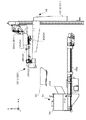
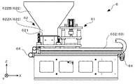
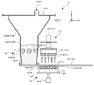
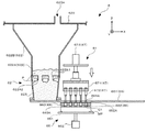
図12は、容器貯留槽および容器搬送手段を示す側面図である。具体的には、図12は、容器貯留槽34および容器搬送手段35を−Y軸方向側から見た図である。
容器貯留槽34は、図12に示すように、容器C1を投入するために鉛直上方側に形成された開口を覆う貯留カバー341と、容器供給用ホッパー33にてダミーパレットDPの上面に落下させた複数の容器C1のうち、ダミーパレットDPの収容部DP1に収容されなかった複数の容器C1を回収する回収口342と、回収口342の下方に形成されるとともに、その内部に貯留している容器C1を搬出する搬出口343とを備えている。
FIG. 12 is a side view showing the container storage tank and the container transport means. Specifically, FIG. 12 is a view of the container storage tank 34 and the container transport means 35 as viewed from the −Y axis direction side.
As shown in FIG. 12, the container storage tank 34 includes a storage cover 341 that covers an opening formed on the vertically upper side for loading the container C1 and a container supply hopper 33 to drop the container cover 341 onto the upper surface of the dummy pallet DP. Of the plurality of containers C1, the recovery port 342 for recovering the plurality of containers C1 not accommodated in the accommodation portion DP1 of the dummy pallet DP, the recovery port 342 is formed below the recovery port 342, and is stored therein. And a carry-out port 343 for carrying out the container C1.

容器搬送手段35は、容器貯留槽34の紙面右側に設けられるとともに、容器貯留槽34に貯留された複数の容器C1を搬送することによって、容器供給用ホッパー33に保持させるバケット機構351と、容器貯留槽34からバケット機構351まで複数の容器C1を搬送するベルトコンベア352とを備えている。
なお、本実施形態では、容器搬送手段35は、バケット機構351と、ベルトコンベア352とを備えているが、これとは異なる構成であってもよい。要するに、容器搬送手段は、貯留手段に貯留された複数の容器を搬送することによって、第1の保持手段および第2の保持手段に保持させることができればよい。
The container transporting unit 35 is provided on the right side of the container storage tank 34 in the plane of the drawing, and transports the plurality of containers C1 stored in the container storage tank 34 to hold the container supply hopper 33 in the container supply hopper 33. A belt conveyor 352 that conveys the plurality of containers C1 from the storage tank 34 to the bucket mechanism 351 is provided.
In addition, in the present embodiment, the container transporting unit 35 includes the bucket mechanism 351 and the belt conveyor 352, but may have a different configuration. In short, the container transporting device only needs to be able to be held by the first holding device and the second holding device by carrying the plurality of containers stored in the storage device.

バケット機構351は、バケット351Aと、昇降機351Bと、保持用コンベア351Cとを備えている。
バケット351Aは、容器貯留槽34側に向かうにしたがって下降するように傾斜するとともに、開閉自在に構成された底面部351A1を有する有底角筒状に形成されている。バケット351Aは、この底面部351A1を閉塞することによって、その内部に複数の容器C1を格納し、この底面を開放することによって、その内部に格納された複数の容器C1を送出する。ここで、図12は、バケット351Aの底面部351A1を開放した状態を示している。
The bucket mechanism 351 includes a bucket 351A, an elevator 351B, and a holding conveyor 351C.
The bucket 351A is formed in a bottomed rectangular tube shape having a bottom surface portion 351A1 that is inclined so as to descend toward the container storage tank 34 side and that can be opened and closed. The bucket 351A closes the bottom surface portion 351A1 to store a plurality of containers C1 therein, and opens the bottom surface to deliver the plurality of containers C1 stored therein. Here, FIG. 12 shows a state in which the bottom surface portion 351A1 of the bucket 351A is opened.

昇降機351Bは、バケット351Aを鉛直上下方向に沿って昇降させることによって、容器貯留槽34の高さ位置(具体的には、ベルトコンベア352の搬送路の上面よりもバケット351Aの上方側の開口が下になる位置)と、容器供給用ホッパー33の高さ位置との間を往復する。ここで、図12は、昇降機351Bにてバケット351Aを容器供給用ホッパー33の高さ位置に上昇させた状態を示している。 The elevator 351B raises and lowers the bucket 351A along the vertical vertical direction, so that the height position of the container storage tank 34 (specifically, the opening on the upper side of the bucket 351A with respect to the upper surface of the transport path of the belt conveyer 352 is larger than the upper surface of the bucket 351A). It reciprocates between the (position below) and the height position of the container supply hopper 33. Here, FIG. 12 shows a state where the bucket 351A is raised to the height position of the container supply hopper 33 by the elevator 351B.

保持用コンベア351Cは、バケット351Aにて送出された複数の容器C1を搬送路351C1に載置し、この搬送路351C1をモータ351C2にて上流側(紙面右側)から下流側(紙面左側)に向かって移動させて複数の容器C1を搬送することによって、容器供給用ホッパー33に保持させる。具体的には、搬送路351C1に載置された複数の容器C1は、保持用コンベア351Cの下流側から容器供給用ホッパー33に向かって落下する。
なお、本実施形態では、バケット機構351は、保持用コンベア351Cを備え、この保持用コンベア351Cは、複数の容器C1を搬送することによって、容器供給用ホッパー33に保持させていた。これに対して、バケット機構351は、例えば、複数の容器C1を押し出す等の他の機構によって、容器供給用ホッパー33に保持させてもよい。
The holding conveyer 351C places a plurality of containers C1 sent out by the bucket 351A on a conveyance path 351C1, and moves the conveyance path 351C1 from an upstream side (right side of the drawing) to a downstream side (left side of the drawing) by a motor 351C2. The container supply hopper 33 holds the container C1 by moving the container C1 and conveying the plurality of containers C1. Specifically, the plurality of containers C1 placed on the transport path 351C1 drop toward the container supply hopper 33 from the downstream side of the holding conveyor 351C.
In the present embodiment, the bucket mechanism 351 includes the holding conveyor 351C, and the holding conveyor 351C conveys the plurality of containers C1 so that the container supply hopper 33 holds the containers. On the other hand, the bucket mechanism 351 may be held in the container supply hopper 33 by another mechanism such as pushing out a plurality of containers C1.

また、保持用コンベア351Cは、搬送路351C1の鉛直上方側に所定の間隔を隔てて設けられた矩形板状のゲート351C3を備えている。このゲート351C3は、搬送路351C1の全幅にわたって配設されている。換言すれば、保持用コンベア351Cは、複数の容器C1を導入する所定面積の入口を有している。
なお、本実施形態では、保持用コンベア351Cは、矩形板状のゲート351C3を備えているが、これを有していなくてもよい。
Further, the holding conveyor 351C is provided with a rectangular plate-shaped gate 351C3 provided at a predetermined distance above the transport path 351C1 in the vertical direction. The gate 351C3 is arranged over the entire width of the transport path 351C1. In other words, the holding conveyor 351C has an inlet having a predetermined area for introducing the plurality of containers C1.
In addition, in the present embodiment, the holding conveyor 351C includes the rectangular plate-shaped gate 351C3, but the gate 351C3 may not be provided.

ゲート351C3は、その上方側の端部にY軸方向に沿ってピン351C4を挿入することによって、保持用コンベア351Cに取り付けられているので、Y軸まわりに搖動自在となっている。したがって、ゲート351C3は、複数の容器C1の通過に際し、その下端を搖動させることができる。
なお、本実施形態では、ゲート351C3は、複数の容器C1の通過に際し、その下端を搖動させることができるように保持用コンベア351Cに取り付けられているが、その下端を搖動させることができるように取り付けられていなくてもよい。
Since the gate 351C3 is attached to the holding conveyor 351C by inserting the pin 351C4 along the Y-axis direction at the upper end thereof, the gate 351C3 can swing freely around the Y-axis. Therefore, the gate 351C3 can swing its lower end when the plurality of containers C1 pass through.
In addition, in the present embodiment, the gate 351C3 is attached to the holding conveyor 351C so that the lower end thereof can be swung when the plurality of containers C1 are passed, but the lower end thereof can be swung. It does not have to be attached.

図13は、容器供給装置の容器供給用配置台の周辺を上方から見た状態を示す模式図である。具体的には、図13は、容器供給装置の容器供給用配置台31A,31Bの周辺を+Z軸方向側から見た状態を模式的に示す図である。
容器供給装置3は、図13に示すように、ダミーパレットDPを搬送することによって、容器供給用配置台31に対して搬入・搬出する前述のパレット搬送手段36を備えている。このパレット搬送手段36は、容器供給用配置台31の+Y軸方向側に配設された上流側パレットコンベア361およびプッシャー362と、容器供給用配置台31の−Y軸方向側に配設されたプラー363および下流側パレットコンベア364と、容器供給用配置台31の+X軸方向側に配設された循環パレットコンベア365とを備えている。
FIG. 13 is a schematic view showing a state in which the periphery of the container supply placement table of the container supply device is viewed from above. Specifically, FIG. 13 is a diagram schematically showing a state in which the periphery of the container supply disposition bases 31A and 31B of the container supply device are viewed from the +Z axis direction side.
As shown in FIG. 13, the container supply device 3 includes the above-described pallet transfer means 36 that transfers the dummy pallet DP to carry it in and out of the container supply placement table 31. The pallet conveying means 36 is provided on the upstream side pallet conveyor 361 and the pusher 362 arranged on the +Y axis direction side of the container supply placement table 31, and on the −Y axis direction side of the container supply placement table 31. It includes a puller 363, a downstream pallet conveyor 364, and a circulating pallet conveyor 365 arranged on the +X axis direction side of the container supply placement table 31.

上流側パレットコンベア361は、容器供給用配置台31Aと隣り合って+Y軸方向側に設けられたダミーパレットDPの搬入待機位置W1にダミーパレットDPを搬送する。
プッシャー362は、上流側パレットコンベア361にてダミーパレットDPの搬入待機位置W1に搬送されたダミーパレットDPを容器供給用配置台31Aに向かって押し出す。
プラー363は、容器供給用配置台31Bと隣り合って−Y軸方向側に設けられたダミーパレットDPの搬出待機位置W2まで容器供給用配置台31Bに配置された2枚のダミーパレットDPを引き出す。
The upstream pallet conveyor 361 conveys the dummy pallet DP to the carry-in standby position W1 of the dummy pallet DP provided on the +Y-axis direction side adjacent to the container supply placement table 31A.
The pusher 362 pushes the dummy pallet DP, which has been transported to the loading standby position W1 of the dummy pallet DP by the upstream pallet conveyor 361, toward the container supply placement table 31A.
The puller 363 pulls out the two dummy pallets DP arranged on the container supply placement table 31B to the carry-out standby position W2 of the dummy pallet DP provided adjacent to the container supply placement table 31B on the −Y axis direction side. ..

下流側パレットコンベア364は、ダミーパレットDPの搬出待機位置W2から循環パレットコンベア365にダミーパレットDPを搬送する。
循環パレットコンベア365は、下流側パレットコンベア364の終点位置に到着したダミーパレットDPを上流側パレットコンベア361の始点位置まで搬送することによって、ダミーパレットDPを循環させる。
The downstream pallet conveyor 364 conveys the dummy pallet DP from the carry-out standby position W2 of the dummy pallet DP to the circulation pallet conveyor 365.
The circulation pallet conveyor 365 circulates the dummy pallet DP by transporting the dummy pallet DP that has arrived at the end point position of the downstream pallet conveyor 364 to the start point position of the upstream pallet conveyor 361.

なお、パレット搬送手段36は、上流側パレットコンベア361と、プッシャー362と、プラー363と、下流側パレットコンベア364と、循環パレットコンベア365とを備えた前述の構成とは異なる構成であってもよい。例えば、パレット搬送手段は、作業者の手作業によって、ダミーパレットを搬送してもよい。要するに、パレット搬送手段は、ダミーパレットを所定方向に沿って搬送することができればよい。 The pallet conveying means 36 may have a configuration different from the above-described configuration including the upstream pallet conveyor 361, the pusher 362, the puller 363, the downstream pallet conveyor 364, and the circulation pallet conveyor 365. .. For example, the pallet carrying means may carry the dummy pallet manually by the operator. In short, the pallet carrying means only needs to be able to carry the dummy pallet along the predetermined direction.

図14は、上流側パレットコンベアの周辺を示す拡大図である。具体的には、図14(A)は、上流側パレットコンベア361の周辺を+Z軸方向側から見た図であり、図14(B)は、上流側パレットコンベア361の周辺を+Y軸方向側から見た図である。
上流側パレットコンベア361は、図13および図14に示すように、ダミーパレットDPの搬入待機位置W1に向かって(−X軸方向に向かって)移動する搬送路361Aと、搬送路361Aの移動方向と平行に設けられるとともに、搬送路361Aの両側に設けられた一対のガイドレール361Bとを備えている。この一対のガイドレール361Bの間隔は、ダミーパレットDPの長手方向の長さよりも僅かに長く設定されている。ここで、ダミーパレットDPの搬入待機位置W1では、搬送路361Aは、容器供給用配置台31と同様に傾斜している(図14(B)参照)。
FIG. 14 is an enlarged view showing the periphery of the upstream pallet conveyor. Specifically, FIG. 14(A) is a view of the periphery of the upstream pallet conveyor 361 viewed from the +Z axis direction side, and FIG. 14(B) is the periphery of the upstream pallet conveyor 361 +Y axis direction side. It is the figure seen from.
As shown in FIGS. 13 and 14, the upstream pallet conveyor 361 has a transport path 361A that moves toward the loading standby position W1 of the dummy pallet DP (toward the −X axis direction), and a transport direction of the transport path 361A. And a pair of guide rails 361B provided on both sides of the transport path 361A. The distance between the pair of guide rails 361B is set to be slightly longer than the length of the dummy pallet DP in the longitudinal direction. Here, at the carry-in standby position W1 of the dummy pallet DP, the transport path 361A is inclined similarly to the container supply placement table 31 (see FIG. 14B).

プッシャー362は、図14に示すように、ダミーパレットDPの側面に当接する当接部362Aと、当接部362AをY軸方向に沿って進退させる進退機構362Bとを備えている。このプッシャー362は、進退機構362Bにて当接部362Aを−Y軸方向側に向かって進出させることによって、上流側パレットコンベア361にてダミーパレットDPの搬入待機位置W1に搬送されたダミーパレットDPを容器供給用配置台31Aに向かって押し出す。 As shown in FIG. 14, the pusher 362 includes an abutting portion 362A that abuts the side surface of the dummy pallet DP, and an advancing/retreating mechanism 362B that moves the abutting portion 362A back and forth along the Y-axis direction. The pusher 362 moves the contact portion 362A toward the −Y axis direction side by the advancing/retreating mechanism 362B, so that the dummy pallet DP conveyed to the carry-in standby position W1 of the dummy pallet DP by the upstream pallet conveyor 361. Is pushed out toward the container supply placement table 31A.

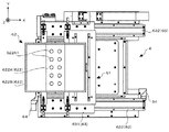
図15は、下流側パレットコンベアの周辺を示す拡大図である。具体的には、図15(A)は、下流側パレットコンベア364の周辺を+Z軸方向側から見た図であり、図15(B)は、下流側パレットコンベア364の周辺を−Y軸方向側から見た図である。
プラー363は、図15に示すように、ダミーパレットDPに形成された2つの貫通孔DP3(図5参照)のうち、−Y軸方向側に形成された貫通孔DP3に挿入するピン363Aと、ピン363AをY軸方向に沿って進退させる進退機構363Bとを備えている。このプラー363は、進退機構363Bにてピン363Aを+Y軸方向側に向かって進出させた後、ダミーパレットDPの貫通孔DP3に挿入し、進退機構363Bにてピン363Aを−Y軸方向側に向かって後退させることによって、ダミーパレットDPの搬出待機位置W2まで容器供給用配置台31Bに配置された2枚のダミーパレットDPを引き出す。
FIG. 15 is an enlarged view showing the periphery of the downstream pallet conveyor. Specifically, FIG. 15A is a view of the periphery of the downstream pallet conveyor 364 as seen from the +Z axis direction side, and FIG. 15B is a view of the periphery of the downstream pallet conveyor 364 in the −Y axis direction. It is the figure seen from the side.
As shown in FIG. 15, the puller 363 includes a pin 363A to be inserted into the through hole DP3 formed on the −Y axis direction side of the two through holes DP3 (see FIG. 5) formed in the dummy pallet DP, An advancing/retreating mechanism 363B for advancing/retreating the pin 363A along the Y-axis direction is provided. In this puller 363, after the pin 363A is advanced toward the +Y axis direction side by the advancing/retreating mechanism 363B, it is inserted into the through hole DP3 of the dummy pallet DP, and the pin 363A is moved toward the −Y axis direction side by the advancing/retreating mechanism 363B. By retracting toward the carry-out standby position W2 of the dummy pallet DP, the two dummy pallets DP arranged on the container supply arranging table 31B are pulled out.

下流側パレットコンベア364は、図13および図15に示すように、ダミーパレットDPの搬出待機位置W2から紙面右方向に向かって移動する搬送路364Aと、プラー363にてダミーパレットDPの搬出待機位置W2まで引き出されたダミーパレットDPを搬送路364Aに向かって押し出すプッシャー364Bと、搬送路364Aの移動方向と平行に設けられるとともに、搬送路364Aの両側に設けられた一対のガイドレール364Cとを備えている。この一対のガイドレール364Cの間隔は、ダミーパレットDPの長手方向の長さよりも僅かに長く設定されている。ここで、ダミーパレットDPの搬出待機位置W2では、搬送路364Aは、容器供給用配置台31と同様に傾斜している(図15(B)参照)。 As shown in FIG. 13 and FIG. 15, the downstream pallet conveyor 364 has a conveyance path 364A that moves from the unloading standby position W2 of the dummy pallet DP to the right side of the drawing, and the pallet 363 unloading standby position of the dummy pallet DP. A pusher 364B that pushes the dummy pallet DP pulled out to W2 toward the transport path 364A, and a pair of guide rails 364C that are provided parallel to the moving direction of the transport path 364A and that are provided on both sides of the transport path 364A are provided. ing. The distance between the pair of guide rails 364C is set to be slightly longer than the length of the dummy pallet DP in the longitudinal direction. Here, at the carry-out standby position W2 of the dummy pallet DP, the transport path 364A is inclined like the container supply placement table 31 (see FIG. 15B).

また、下流側パレットコンベア364は、図15に示すように、ダミーパレットDPの搬出待機位置W2の状態を容器供給用配置台31と同様に傾斜させた状態と、水平にした状態とに切り替える切替機構364Dを備えている。
切替機構364Dは、ダミーパレットDPの搬出待機位置W2を有する台座364D1と、台座364D1をY軸まわりに回動自在に支持する台座支持部364D2とを備えている。この切替機構364Dは、モータ(図示略)の駆動力によって台座364D1をY軸まわりに回動させることによって、ダミーパレットDPの搬出待機位置W2の状態を容器供給用配置台31と同様に傾斜させた状態と、水平にした状態とに切り替える。
Further, as shown in FIG. 15, the downstream pallet conveyor 364 switches the state of the dummy pallet DP at the carry-out standby position W2 between a state in which the dummy pallet DP is in the standby state W2 and a state in which the dummy pallet DP is inclined, as in the case of the container supply pedestal 31. The mechanism 364D is provided.
The switching mechanism 364D includes a pedestal 364D1 having a carry-out standby position W2 for the dummy pallet DP, and a pedestal support portion 364D2 that rotatably supports the pedestal 364D1 around the Y axis. The switching mechanism 364D causes the pedestal 364D1 to rotate about the Y-axis by the driving force of a motor (not shown) to tilt the state of the dummy pallet DP at the carry-out standby position W2 in the same manner as the container supply placement table 31. Switch between open and level.

循環パレットコンベア365は、図13に示すように、ダミーパレットDPを載置するとともに、+Y軸方向に向かって移動することによって、下流側パレットコンベア364の終点位置から上流側パレットコンベア361の始点位置まで搬送する搬送路365Aと、搬送路365Aの終点位置に到着したダミーパレットDPの+X軸方向側の側面に当接するプレート365Bと、プレート365BをX軸方向に沿って進退させる進退機構365Cとを備えている。この循環パレットコンベア365は、進退機構365Cにてプレート365Bを−X軸方向に向かって進出させることによって、上流側パレットコンベア361の始点位置に到着したダミーパレットDPを上流側パレットコンベア361に送り出す。 As shown in FIG. 13, the circulating pallet conveyor 365 mounts the dummy pallet DP and moves in the +Y-axis direction to move from the end point position of the downstream pallet conveyor 364 to the start point position of the upstream pallet conveyor 361. A transport path 365A for transporting up to, a plate 365B that contacts the side surface on the +X axis direction side of the dummy pallet DP that has arrived at the end point position of the transport path 365A, and an advancing/retreating mechanism 365C that advances and retracts the plate 365B along the X axis direction. I have it. The circulating pallet conveyor 365 feeds the dummy pallet DP that has arrived at the starting point position of the upstream pallet conveyor 361 to the upstream pallet conveyor 361 by advancing the plate 365B in the −X axis direction by the advancing/retreating mechanism 365C.

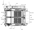
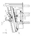
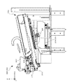
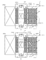
図16は、容器供給装置の容器補充機構の上面図および側面図である。具体的には、図16(A)は、容器補充機構37を+Z軸方向側から見た上面図であり、図16(B)は、容器補充機構37を−Y軸方向側から見た側面図である。
容器供給装置3は、図16に示すように、容器供給機構3A,3Bにて容器C1を供給できなかった収容部DP1に容器C1を補充する前述の容器補充機構37を備えている。
FIG. 16 is a top view and a side view of the container replenishing mechanism of the container supply device. Specifically, FIG. 16(A) is a top view of the container replenishing mechanism 37 seen from the +Z axis direction side, and FIG. 16(B) is a side view of the container replenishing mechanism 37 seen from the −Y axis direction side. It is a figure.
As shown in FIG. 16, the container supply device 3 includes the above-described container replenishment mechanism 37 that replenishes the container C1 to the storage portion DP1 that could not supply the container C1 with the container supply mechanisms 3A and 3B.

下流側パレットコンベア364は、ダミーパレットDPの貫通孔DP3に挿入するピン(図示略)と、このピンを+X軸方向側に向かって移動させる移動機構(図示略)とを備えている。この下流側パレットコンベア364は、ダミーパレットDPの貫通孔DP3にピンを挿入し、このピンを移動機構にて移動させることによって、ダミーパレットDPを搬送する。具体的には、下流側パレットコンベア364は、ダミーパレットDPの1枚分の距離ごとにピンの移動および停止を繰り返して間欠的に移動させることによって、ダミーパレットDPを+X軸方向側に向かって間欠的に搬送する。 The downstream pallet conveyor 364 includes a pin (not shown) that is inserted into the through hole DP3 of the dummy pallet DP and a moving mechanism (not shown) that moves the pin toward the +X axis direction. The downstream pallet conveyor 364 conveys the dummy pallet DP by inserting a pin into the through hole DP3 of the dummy pallet DP and moving the pin by the moving mechanism. Specifically, the downstream pallet conveyor 364 moves the dummy pallet DP toward the +X axis direction side by intermittently moving by repeatedly moving and stopping the pins for each distance of one dummy pallet DP. Transport intermittently.

容器補充機構37は、第1異常検出センサ371および第2異常検出センサ372と、姿勢修正手段373と、CCDカメラ374と、仮置台375と、第1のアームロボット376と、第2のアームロボット377とを備えている。
以下、仮置台375の−X軸方向側に位置するダミーパレットDPの停止位置をDPS1,DPS2とし、仮置台375の+X軸方向側に位置するダミーパレットDPの停止位置をDPS3とする。
The container replenishment mechanism 37 includes a first abnormality detection sensor 371 and a second abnormality detection sensor 372, a posture correction unit 373, a CCD camera 374, a temporary stand 375, a first arm robot 376, and a second arm robot. 377 and.
Hereinafter, the stop positions of the dummy pallets DP located on the −X axis direction side of the temporary placing table 375 are referred to as DPS1 and DPS2, and the stop positions of the dummy pallets DP located on the +X axis direction side of the temporary placing table 375 are referred to as DPS3.

なお、図16(A)では、姿勢修正手段373およびCCDカメラ374の図示は省略し、図16(B)では、第1異常検出センサ371、第2異常検出センサ372、第1のアームロボット376および第2のアームロボット377の図示は省略している。また、第1のアームロボット376および第2のアームロボット377は、前述した図6にも図示している。 16A, the posture correction unit 373 and the CCD camera 374 are not shown, and in FIG. 16B, the first abnormality detection sensor 371, the second abnormality detection sensor 372, and the first arm robot 376. The illustration of the second arm robot 377 is omitted. The first arm robot 376 and the second arm robot 377 are also shown in FIG. 6 described above.

第1異常検出センサ371は、図16(A)に示すように、下流側パレットコンベア364の−X軸方向側に配設されている。この第1異常検出センサ371は、ダミーパレットDPの上面に沿って+Y軸方向側に光を出射することによって、下流側パレットコンベア364にて停止位置DPS1に搬送されて停止したダミーパレットDPの収容部DP1に供給された容器C1の浮きを検出する。
第2異常検出センサ372は、第1異常検出センサ371の+X軸方向側に配設されている。この第2異常検出センサ372は、第1異常検出センサ371と同様に、ダミーパレットDPの上面に沿って+Y軸方向側に光を出射することによって、下流側パレットコンベア364にて停止位置DPS2に搬送されて停止したダミーパレットDPの収容部DP1に供給された容器C1の浮きを検出する。
As shown in FIG. 16A, the first abnormality detection sensor 371 is arranged on the −X axis direction side of the downstream pallet conveyor 364. The first abnormality detection sensor 371 emits light in the +Y-axis direction along the upper surface of the dummy pallet DP so that the dummy pallet DP that has been conveyed to the stop position DPS1 by the downstream pallet conveyor 364 and accommodated therein is stored. The floating of the container C1 supplied to the portion DP1 is detected.
The second abnormality detection sensor 372 is arranged on the +X axis direction side of the first abnormality detection sensor 371. Like the first abnormality detection sensor 371, the second abnormality detection sensor 372 emits light toward the +Y-axis direction along the upper surface of the dummy pallet DP so that the downstream pallet conveyor 364 moves to the stop position DPS2. The floating of the container C1 supplied to the accommodation portion DP1 of the dummy pallet DP that has been conveyed and stopped is detected.

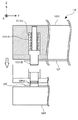
図17は、姿勢修正手段を側方から見た状態を示す模式図である。
姿勢修正手段373は、図16および図17に示すように、下流側パレットコンベア364にて停止位置DPS1に搬送されて停止したダミーパレットDPの収容部DP1に対して下面側から挿入することによって、ダミーパレットDPの収容部DP1に収容された容器C1に当接して押し上げる複数の棒状体373A1を有するプレート373Aと、プレート373Aを昇降させるシリンダ373Bとを備えている。この姿勢修正手段373は、下流側パレットコンベア364にて搬送されるダミーパレットDPの収容部DP1に供給された容器C1の姿勢を修正する。
FIG. 17 is a schematic diagram showing a state in which the posture correcting means is viewed from the side.
As shown in FIGS. 16 and 17, the posture correcting means 373 is inserted from the lower surface side into the accommodating portion DP1 of the dummy pallet DP which is conveyed to the stop position DPS1 by the downstream pallet conveyor 364 and stopped. A plate 373A having a plurality of rod-shaped bodies 373A1 that abuts and pushes up the container C1 stored in the storage portion DP1 of the dummy pallet DP, and a cylinder 373B that moves the plate 373A up and down are provided. The attitude correction unit 373 corrects the attitude of the container C1 supplied to the accommodation portion DP1 of the dummy pallet DP conveyed by the downstream pallet conveyor 364.

図18は、姿勢修正手段にて容器の姿勢を修正している状態を示す図である。具体的には、図18(A)は、プレート373Aを上昇させた状態を示す図であり、図18(B)は、プレート373Aを下降させた状態を示す図である。
姿勢修正手段373は、図18(A)に示すように、シリンダ373Bにてプレート373Aを上昇させることによって、ダミーパレットDPの収容部DP1に収容された容器C1に複数の棒状体373A1を当接させて押し上げる(図中上向矢印参照)。この際、シリンダ373Bは、ダミーパレットDPの上面に対して棒状体373A1の上面を鉛直下方側に位置させるようにプレート373Aを上昇させる。換言すれば、シリンダ373Bは、ダミーパレットDPの上面から棒状体373A1を突出させない程度にプレート373Aを上昇させる。
FIG. 18 is a diagram showing a state in which the posture of the container is corrected by the posture correcting means. Specifically, FIG. 18A is a diagram showing a state in which the plate 373A is raised, and FIG. 18B is a diagram showing a state in which the plate 373A is lowered.
As shown in FIG. 18A, the posture correcting means 373 raises the plate 373A with the cylinder 373B to bring the plurality of rod-shaped bodies 373A1 into contact with the container C1 accommodated in the accommodating portion DP1 of the dummy pallet DP. And push it up (see upward arrow in the figure). At this time, the cylinder 373B raises the plate 373A so that the upper surface of the rod-shaped body 373A1 is positioned vertically below the upper surface of the dummy pallet DP. In other words, the cylinder 373B raises the plate 373A to the extent that the rod-shaped body 373A1 does not project from the upper surface of the dummy pallet DP.

その後、姿勢修正手段373は、図18(B)に示すように、シリンダ373Bにてプレート373Aを下降させる(図中下向矢印参照)。ここで、前述したように、容器C1は、有底筒状に形成されるとともに、頂部から底部に向かうにしたがって僅かに縮径するように形成された断面六角形状の胴体C11を有しているので、姿勢修正手段373は、プレート373Aを下降させることによって、ダミーパレットDPの収容部DP1に供給された容器C1の姿勢を修正することができる。
したがって、本実施形態では、姿勢修正手段373は、ダミーパレットDPの上面側からダミーパレットDPの収容部DP1に供給された容器C1の姿勢を、ダミーパレットDPの下面側からダミーパレットDPの収容部DP1に棒状体373A1を挿入して容器C1の底面に当接させて修正する。
After that, the posture correcting means 373 moves the plate 373A down by the cylinder 373B as shown in FIG. 18B (see the downward arrow in the figure). Here, as described above, the container C1 has a body C11 having a hexagonal cross-section, which is formed in a cylindrical shape with a bottom and is formed so as to be slightly reduced in diameter from the top to the bottom. Therefore, the attitude correction unit 373 can correct the attitude of the container C1 supplied to the accommodation portion DP1 of the dummy pallet DP by lowering the plate 373A.
Therefore, in the present embodiment, the posture correction unit 373 sets the posture of the container C1 supplied from the upper surface side of the dummy pallet DP to the storage portion DP1 of the dummy pallet DP to the storage portion of the dummy pallet DP from the lower surface side of the dummy pallet DP. The rod-shaped body 373A1 is inserted into DP1 and brought into contact with the bottom surface of the container C1 for correction.

CCDカメラ374は、図16(B)に示すように、下流側パレットコンベア364の鉛直上方に配設されている。このCCDカメラ374は、下流側パレットコンベア364にて停止位置DPS2に搬送されて停止したダミーパレットDPを撮像することによって、ダミーパレットDPの収容部DP1の状態を検出する。 As shown in FIG. 16B, the CCD camera 374 is arranged vertically above the downstream pallet conveyor 364. The CCD camera 374 detects the state of the accommodating portion DP1 of the dummy pallet DP by capturing an image of the dummy pallet DP which is conveyed to the stop position DPS2 by the downstream pallet conveyor 364 and stopped.

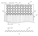
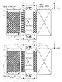
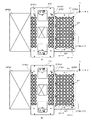
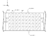
図19は、CCDカメラにて検出されるダミーパレットの収容部の状態を示す図である。
具体的には、CCDカメラ374は、図19に示すように、下流側パレットコンベア364にて搬送されるダミーパレットDPの収容部DP1を、容器C1を供給すべき供給用収容部DP1Fと、容器C1を供給しなくてもよい予備用収容部DP1Sとに区分けしている。
ここで、CCDカメラ374は、ダミーパレットDPの収容部DP1を長手方向(行方向)に沿って2つの領域に分割することによって、供給用収容部DP1Fおよび予備用収容部DP1Sに区分けている。具体的には、CCDカメラ374は、ダミーパレットDPの収容部DP1を長手方向に沿って2つの領域に分割することによって、長手方向(行方向)に沿って等間隔に10個の収容部DP1を配列しているとともに、短手方向(列方向)に沿って等間隔に5個の収容部DP1を配列している供給用収容部DP1Fと、長手方向(行方向)に沿って等間隔に10個の収容部DP1を配列しているとともに、短手方向(列方向)に沿って等間隔に1個の収容部DP1を配列している予備用収容部DP1Sとに区分けている。
FIG. 19 is a diagram showing a state of the accommodation portion of the dummy pallet detected by the CCD camera.
Specifically, as shown in FIG. 19, the CCD camera 374 includes a container DP1F for supplying the container C1 and a container DP1F for supplying the container C1 to the container DP1 of the dummy pallet DP conveyed by the downstream pallet conveyor 364. It is divided into a spare accommodating portion DP1S that does not need to be supplied with C1.
Here, the CCD camera 374 is divided into a supply accommodating part DP1F and a spare accommodating part DP1S by dividing the accommodating part DP1 of the dummy pallet DP into two regions along the longitudinal direction (row direction). Specifically, the CCD camera 374 divides the housing portion DP1 of the dummy pallet DP into two regions along the longitudinal direction, so that the ten housing portions DP1 are arranged at equal intervals along the longitudinal direction (row direction). And the supply accommodating portions DP1F in which five accommodating portions DP1 are arranged at equal intervals along the lateral direction (column direction) and at equal intervals along the longitudinal direction (row direction). The 10 accommodating portions DP1 are arranged and divided into a preliminary accommodating portion DP1S in which one accommodating portion DP1 is arranged at equal intervals along the lateral direction (row direction).

なお、本実施形態では、CCDカメラ374は、ダミーパレットDPの収容部DP1を行方向に沿って2つの領域に分割することによって、供給用収容部DP1Fおよび予備用収容部DP1Sに区分けているが、列方向に沿って2つの領域に分割することによって、供給用収容部DP1Fおよび予備用収容部DP1Sに区分けてもよい。また、CCDカメラ374は、行方向および列方向とは異なる条件に基づいて、供給用収容部DP1Fおよび予備用収容部DP1Sに区分けてもよい。 In the present embodiment, the CCD camera 374 is divided into the supply accommodating part DP1F and the spare accommodating part DP1S by dividing the accommodating part DP1 of the dummy pallet DP into two regions along the row direction. It may be divided into two regions along the column direction to be the supply accommodating portion DP1F and the spare accommodating portion DP1S. Further, the CCD camera 374 may be divided into the supply accommodating portion DP1F and the spare accommodating portion DP1S based on conditions different from the row direction and the column direction.

そして、CCDカメラ374は、容器供給用ホッパー33Aおよび容器供給用ホッパー33Bに保持された複数の容器C1をダミーパレットDPの上面に向かって供給させた後、供給用収容部DP1Fのうち、容器C1を供給されていない空の供給用収容部DP1Fと、予備用収容部DP1Sのうち、容器C1を供給されている予備用収容部DP1Sとを検出する。このように、本実施形態では、CCDカメラ374は、収容部検出手段として機能している。 Then, the CCD camera 374 supplies the plurality of containers C1 held by the container supply hopper 33A and the container supply hopper 33B toward the upper surface of the dummy pallet DP, and then supplies the plurality of containers C1 in the supply container DP1F. Of the empty supply accommodation portion DP1F that is not supplied with the container C1 and the spare accommodation portion DP1S that is supplied with the container C1 among the preliminary accommodation portions DP1S are detected. As described above, in the present embodiment, the CCD camera 374 functions as a container detecting unit.

例えば、図19では、左上隅の収容部DP1を1行目1列目とすると、CCDカメラ374は、供給用収容部DP1Fのうち、容器C1を供給されていない空の供給用収容部DP1Fとして、2行目3列目、3行目7列目、および4行目2列目の3つの供給用収容部DP1Fを検出する。また、CCDカメラ374は、予備用収容部DP1Sのうち、容器C1を供給されている予備用収容部DP1Sとして、6行目4列目および6行目8列目以外の8つの予備用収容部DP1Sを検出する。 For example, in FIG. 19, assuming that the storage unit DP1 at the upper left corner is the first row and the first column, the CCD camera 374 is an empty supply storage unit DP1F in which the container C1 is not supplied among the supply storage units DP1F. The three supply accommodating portions DP1F in the second row, third column, third row, seventh column, and fourth row, second column are detected. Further, the CCD camera 374 includes eight spare accommodating portions other than the sixth row, fourth column and sixth row and eighth column as the spare accommodating portion DP1S supplied with the container C1 among the spare accommodating portions DP1S. Detect DP1S.

仮置台375は、図16に示すように、CCDカメラ374の+X軸方向側に位置し、下流側パレットコンベア364の鉛直上方に配設されるとともに、複数の容器C1を仮置きする複数の仮置部375Aを有している。なお、ダミーパレットDPは、仮置台375の鉛直下方側を通過する。
したがって、本実施形態では、仮置台375は、複数の容器C1を仮置きする複数の仮置部375Aを有する容器仮置手段として機能する。
なお、本実施形態では、容器供給装置3は、仮置台375を備えているが、これを備えていなくてもよい。
As shown in FIG. 16, the temporary placing table 375 is located on the +X-axis direction side of the CCD camera 374, is arranged above the downstream pallet conveyor 364 in the vertical direction, and temporarily holds a plurality of containers C1. It has a mounting portion 375A. The dummy pallet DP passes vertically below the temporary stand 375.
Therefore, in the present embodiment, the temporary placing table 375 functions as a container temporary placing means having a plurality of temporary placing portions 375A for temporarily placing the plurality of containers C1.
In addition, in the present embodiment, the container supply device 3 includes the temporary placing table 375, but may not include the temporary placing table 375.

具体的には、仮置台375は、第1のアームロボット376側に設けられた第1仮置領域375A1と、第2のアームロボット377側に設けられた第2仮置領域375A2とを備えている。
なお、仮置台375は、第1仮置領域375A1および第2仮置領域375A2の間に形成された断面矩形状の3つの貫通孔を有し、第1仮置領域375A1および第2仮置領域375A2を明確に区切っている。
Specifically, the temporary placing table 375 includes a first temporary placing area 375A1 provided on the first arm robot 376 side and a second temporary placing area 375A2 provided on the second arm robot 377 side. There is.
The temporary placement table 375 has three through holes having a rectangular cross section formed between the first temporary placement area 375A1 and the second temporary placement area 375A2, and the first temporary placement area 375A1 and the second temporary placement area 375A1. 375A2 is clearly delimited.

第1仮置領域375A1は、長手方向(行方向)に沿って等間隔に10個の仮置部375Aを配列しているとともに、短手方向(列方向)に沿って等間隔に2個の仮置部375Aを配列している。換言すれば、第1仮置領域375A1は、格子点状に20個の仮置部375Aを有している。
第2仮置領域375A2は、長手方向(行方向)に沿って等間隔に10個の仮置部375Aを配列しているとともに、短手方向(列方向)に沿って等間隔に2個の仮置部375Aを配列している。換言すれば、第2仮置領域375A2は、格子点状に20個の仮置部375Aを有している。
なお、本実施形態では、第1仮置領域375A1および第2仮置領域375A2は、格子点状に20個の仮置部375Aを有しているが、20とは異なる2以上の個数の仮置部を有していればよい。また、本実施形態では、仮置部は、格子点状に配列されているが、格子点状に配列していなくてもよく、その並び方は規則性を有していなくてもよい。
The first temporary placement region 375A1 has ten temporary placement portions 375A arranged at equal intervals along the longitudinal direction (row direction), and also has two temporary placement portions 375A1 at equal intervals along the lateral direction (column direction). The temporary storage portions 375A are arranged. In other words, the first temporary placement area 375A1 has 20 temporary placement portions 375A in a grid point shape.
The second temporary placement region 375A2 has ten temporary placement portions 375A arranged at equal intervals along the longitudinal direction (row direction), and also has two temporary placement portions 375A2 at equal intervals along the lateral direction (column direction). The temporary storage portions 375A are arranged. In other words, the second temporary placement area 375A2 has 20 temporary placement portions 375A in a lattice point shape.
In addition, in the present embodiment, the first temporary placement area 375A1 and the second temporary placement area 375A2 have 20 temporary placement portions 375A in the shape of a lattice point, but two or more temporary placement areas different from 20 are provided. It suffices to have a storage part. In addition, in the present embodiment, the temporary placement parts are arranged in the shape of grid points, but they may not be arranged in the shape of grid points, and their arrangement may not have regularity.

ここで、仮置台375の仮置部375Aの形状は、ダミーパレットDPの収容部DP1の形状と同一に形成されている。
したがって、仮置台375の仮置部375Aの内部に容器C1を収容すると、フランジC12は仮置部375Aの外部に突出し、胴体C11は仮置部375Aの内部に収容される。換言すれば、容器C1は、頂部を鉛直上方側に位置させるとともに、底部を鉛直下方側に位置させた一定の姿勢を取るようにして仮置部375Aに収容され、これとは逆の姿勢を取るようにして仮置部375Aに収容されることはない。
また、前述したように、容器C1は、有底筒状に形成されるとともに、頂部から底部に向かうにしたがって僅かに縮径するように形成された断面六角形状の胴体C11を有しているので、仮置部375Aに入り込みやすくなっている。
Here, the shape of the temporary placing portion 375A of the temporary placing table 375 is formed to be the same as the shape of the accommodation portion DP1 of the dummy pallet DP.
Therefore, when the container C1 is housed inside the temporary placing part 375A of the temporary placing table 375, the flange C12 projects outside the temporary placing part 375A, and the body C11 is housed inside the temporary placing part 375A. In other words, the container C1 is housed in the temporary placement portion 375A so that the container C1 has a fixed position in which the top is positioned vertically upward and the bottom is positioned vertically downward. It is not stored in the temporary storage portion 375A as if it were taken.
Further, as described above, the container C1 is formed in the shape of a cylinder with a bottom, and has the body C11 having a hexagonal cross-section formed so as to be slightly reduced in diameter from the top to the bottom. , It is easy to get into the temporary storage portion 375A.

第1のアームロボット376は、図6および図16(A)に示すように、ロボット本体376Aと、容器C1を保持するためにロボット本体376Aの先端に設けられたハンド376B(図20および図21参照)とを備え、仮置台375の−Y軸方向側に配設されている。
ロボット本体376Aは、ハンド376Bを移動させることによって、第1仮置領域375A1の仮置部375Aのそれぞれと、下流側パレットコンベア364にて停止位置DPS2に搬送されて停止したダミーパレットDPの収容部DP1のそれぞれとを往来する。
As shown in FIGS. 6 and 16A, the first arm robot 376 includes a robot body 376A and a hand 376B provided at the tip of the robot body 376A for holding the container C1 (see FIGS. 20 and 21). , And is arranged on the −Y axis direction side of the temporary placing table 375.
By moving the hand 376B, the robot main body 376A moves to the temporary placement section 375A of the first temporary placement area 375A1 and the storage section of the dummy pallet DP that is transported to the stop position DPS2 by the downstream pallet conveyor 364 and stopped. Travels to and from each DP1.

第2のアームロボット377は、図6および図16(A)に示すように、ロボット本体377Aと、容器C1を保持するためにロボット本体377Aの先端に設けられたハンド377B(図20および図21参照)とを備え、第1のアームロボット376の+X軸方向側に配設されている。
ロボット本体377Aは、ハンド377Bを移動させることによって、第2仮置領域375A2の仮置部375Aのそれぞれと、下流側パレットコンベア364にて停止位置DPS3に搬送されて停止したダミーパレットDPの収容部DP1のそれぞれとを往来する。
As shown in FIGS. 6 and 16A, the second arm robot 377 includes a robot body 377A and a hand 377B (FIGS. 20 and 21) provided at the tip of the robot body 377A for holding the container C1. , And are arranged on the +X axis direction side of the first arm robot 376.
The robot main body 377A moves the hand 377B to move each of the temporary placement sections 375A of the second temporary placement area 375A2 and the storage section of the dummy pallet DP that is transported to the stop position DPS3 by the downstream pallet conveyor 364 and stopped. Travels to and from each DP1.

図20は、予備用収容部に供給されている容器を空の供給用収容部に補充している状態を示す図である。具体的には、図20(A)は、ハンド376B,377Bを予備用収容部DP1Sに供給されている容器C1の位置に移動させた状態を示す図であり、図20(B)は、ハンド376B,377Bを空の供給用収容部DP1Fの位置に移動させた状態を示す図である。なお、図20では、ハッチングを付して容器C1を図示している。 FIG. 20 is a diagram showing a state in which the container supplied to the preliminary accommodating portion is being replenished to the empty supply accommodating portion. Specifically, FIG. 20(A) is a diagram showing a state in which the hands 376B, 377B have been moved to the position of the container C1 supplied to the preliminary accommodating portion DP1S, and FIG. 20(B) shows the hands. It is a figure which shows the state which moved 376B and 377B to the position of the empty accommodation part DP1F for supply. Note that, in FIG. 20, the container C1 is illustrated with hatching.

第1のアームロボット376は、CCDカメラ374の検出結果に基づいて、図20(A)に示すように、下流側パレットコンベア364にて停止位置DPS2に搬送されて停止したダミーパレットDPの予備用収容部DP1Sに供給されている容器C1をハンド376Bにて保持する。そして、第1のアームロボット376は、CCDカメラ374の検出結果に基づいて、図20(B)に示すように、ハンド376Bを移動させることによって、この容器C1を下流側パレットコンベア364にて停止位置DPS2に搬送されて停止したダミーパレットDPの空の供給用収容部DP1Fに補充する(図中左向矢印参照)。 Based on the detection result of the CCD camera 374, the first arm robot 376, as shown in FIG. 20(A), reserves the dummy pallet DP that has been transported to the stop position DPS2 by the downstream pallet conveyor 364 and stopped. The container C1 supplied to the housing portion DP1S is held by the hand 376B. Then, the first arm robot 376 stops the container C1 at the downstream pallet conveyor 364 by moving the hand 376B based on the detection result of the CCD camera 374, as shown in FIG. The dummy pallet DP, which has been transported to the position DPS2 and stopped, is replenished in the empty supply container DP1F (see the arrow pointing left in the drawing).

また、第2のアームロボット377は、CCDカメラ374の検出結果に基づいて、図20(A)に示すように、下流側パレットコンベア364にて停止位置DPS3に搬送されて停止したダミーパレットDPの予備用収容部DP1Sに供給されている容器C1をハンド377Bにて保持する。そして、第2のアームロボット377は、CCDカメラ374の検出結果に基づいて、図20(B)に示すように、ハンド377Bを移動させることによって、この容器C1を下流側パレットコンベア364にて停止位置DPS3に搬送されて停止したダミーパレットDPの空の供給用収容部DP1Fに補充する(図中左向矢印参照)。 Further, the second arm robot 377, based on the detection result of the CCD camera 374, moves the dummy pallet DP conveyed to the stop position DPS3 and stopped by the downstream pallet conveyor 364 as shown in FIG. The container C1 supplied to the preliminary accommodating portion DP1S is held by the hand 377B. Then, the second arm robot 377 stops the container C1 at the downstream pallet conveyor 364 by moving the hand 377B based on the detection result of the CCD camera 374, as shown in FIG. The dummy pallet DP, which has been transported to the position DPS3 and stopped, is replenished in the empty supply accommodation portion DP1F (see the arrow pointing left in the drawing).

このように、本実施形態では、第1のアームロボット376および第2のアームロボット377は、CCDカメラ374の検出結果に基づいて、予備用収容部DP1Sに供給されている容器C1を空の供給用収容部DP1Fに補充する容器補充手段として機能する。また、第1のアームロボット376は、下流側パレットコンベア364の上流側に設けられた第1の容器補充手段として機能し、第2のアームロボット377は、下流側パレットコンベア364の上流側に設けられた第2の容器補充手段として機能する。
なお、本実施形態では、容器供給装置3は、2台のアームロボット376,377を備えているが、1台であってもよく、3台以上であってもよい。要するに、容器供給装置は、少なくとも1つの容器補充手段を備えていればよい。
As described above, in the present embodiment, the first arm robot 376 and the second arm robot 377 supply the empty container C1 supplied to the preliminary accommodating portion DP1S based on the detection result of the CCD camera 374. It functions as a container replenishing means for replenishing the container accommodating portion DP1F. Further, the first arm robot 376 functions as a first container replenishing means provided on the upstream side of the downstream pallet conveyor 364, and the second arm robot 377 is provided on the upstream side of the downstream pallet conveyor 364. And functions as a second container replenishing means.
In addition, in this embodiment, the container supply device 3 includes two arm robots 376 and 377, but the number may be one, or three or more. In short, the container supply device may include at least one container replenishing means.

図21は、仮置台の仮置部に収容されている容器を空の供給用収容部に補充している状態を示す図である。具体的には、図21(A)は、ハンド376B,377Bを仮置台375の仮置部375Aに収容されている容器C1の位置に移動させた状態を示す図であり、図21(B)は、ハンド376B,377Bを空の供給用収容部DP1Fの位置に移動させた状態を示す図である。なお、図21では、ハッチングを付して容器C1を図示している。 FIG. 21 is a diagram showing a state where a container accommodated in the temporary placement section of the temporary placement table is being replenished in an empty supply accommodation section. Specifically, FIG. 21A is a diagram showing a state in which the hands 376B and 377B have been moved to the position of the container C1 housed in the temporary placing section 375A of the temporary placing table 375, and FIG. [Fig. 6] is a view showing a state in which hands 376B, 377B have been moved to the position of an empty supply accommodation portion DP1F. Note that, in FIG. 21, the container C1 is illustrated with hatching.

第1のアームロボット376は、図21(A)に示すように、第1仮置領域375A1の仮置部375Aに仮置きされている容器C1をハンド376Bにて保持する。そして、第1のアームロボット376は、CCDカメラ374の検出結果に基づいて、図21(B)に示すように、ハンド376Bを移動させることによって、この容器C1を下流側パレットコンベア364にて停止位置DPS2に搬送されて停止したダミーパレットDPの空の供給用収容部DP1Fに補充する(図中左向矢印参照)。 As shown in FIG. 21A, the first arm robot 376 holds the container C1 temporarily placed in the temporary placement section 375A of the first temporary placement area 375A1 with the hand 376B. Then, the first arm robot 376 stops the container C1 at the downstream pallet conveyor 364 by moving the hand 376B based on the detection result of the CCD camera 374, as shown in FIG. The dummy pallet DP, which has been transported to the position DPS2 and stopped, is replenished in the empty supply container DP1F (see the arrow pointing left in the drawing).

また、第2のアームロボット377は、図21(A)に示すように、第2仮置領域375A2の仮置部375Aに仮置きされている容器C1をハンド377Bにて保持する。そして、第2のアームロボット377は、CCDカメラ374の検出結果に基づいて、図21(B)に示すように、ハンド377Bを移動させることによって、この容器C1を下流側パレットコンベア364にて停止位置DPS3に搬送されて停止したダミーパレットDPの空の供給用収容部DP1Fに補充する(図中右向矢印参照)。 The second arm robot 377 holds the container C1 temporarily placed in the temporary placement portion 375A of the second temporary placement area 375A2 with the hand 377B, as shown in FIG. Then, the second arm robot 377 stops the container C1 at the downstream pallet conveyor 364 by moving the hand 377B based on the detection result of the CCD camera 374 as shown in FIG. The dummy pallet DP, which has been conveyed to the position DPS3 and stopped, is replenished in the empty supply accommodating portion DP1F (see the arrow pointing right in the drawing).

このように、本実施形態では、第1のアームロボット376および第2のアームロボット377は、CCDカメラ374の検出結果に基づいて、仮置台375の仮置部375Aに仮置きされている容器C1を空の供給用収容部DP1Fに補充する容器補充手段として機能する。 As described above, in the present embodiment, the first arm robot 376 and the second arm robot 377, based on the detection result of the CCD camera 374, temporarily store the container C1 in the temporary placing portion 375A of the temporary placing table 375. Function as a container replenishing means for replenishing the empty supply accommodating portion DP1F.

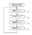
図22は、容器供給装置の概略構成を示す機能ブロック図である。
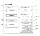
さらに、容器供給装置3は、図22に示すように、この容器供給装置3の全体を制御する容器供給用制御手段38を備えている。
容器供給用制御手段38は、CPU(Central Processing Unit)や、メモリなどによって構成され、このメモリに記憶された所定のプログラムに従って情報処理を実行する。この容器供給用制御手段38は、容器搬送部381と、容器供給部382と、パレット搬送部383と、容器補充部384とを備えている。
FIG. 22 is a functional block diagram showing a schematic configuration of the container supply device.
Further, as shown in FIG. 22, the container supply device 3 includes a container supply control means 38 that controls the entire container supply device 3.
The container supply control unit 38 includes a CPU (Central Processing Unit), a memory, and the like, and executes information processing according to a predetermined program stored in the memory. The container supply control unit 38 includes a container transfer section 381, a container supply section 382, a pallet transfer section 383, and a container replenishment section 384.

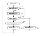
容器搬送部381は、容器投入部381Aと、投入停止部381Bと、容器移動部381Cとを備え、容器搬送手段35を制御して容器貯留槽34に貯留された複数の容器C1を搬送することによって、容器供給用ホッパー33に保持させる。
以下、容器搬送部381を構成する各部381A〜381Cの機能について詳細に説明する。
The container transfer unit 381 includes a container input unit 381A, an input stop unit 381B, and a container moving unit 381C, and controls the container transfer unit 35 to transfer the plurality of containers C1 stored in the container storage tank 34. By the container supply hopper 33.
The functions of the respective units 381A to 381C constituting the container transporting unit 381 will be described in detail below.

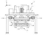
図23は、バケットの内部に複数の容器を投入している状態を示す図である。
容器投入部381Aは、図23に示すように、バケット351Aを容器貯留槽34の高さ位置に移動させた後(図中下向矢印)、バケット351Aの底面部351A1を閉塞する。そして、容器投入部381Aは、ベルトコンベア352に搬送路の移動を開始させることによって(図中右向矢印)、ベルトコンベア352にて搬送される複数の容器C1をバケット351Aの内部に投入する。
ここで、ベルトコンベア352は、容器貯留槽34に貯留された複数の容器C1を導入する所定面積の入口(容器貯留槽34の搬出口343)を有しているので、バケット351Aに投入される単位時間あたりの容器C1の数量を一定にすることができる。
FIG. 23 is a diagram showing a state in which a plurality of containers are loaded inside the bucket.
As shown in FIG. 23, the container feeding unit 381A closes the bottom surface portion 351A1 of the bucket 351A after moving the bucket 351A to the height position of the container storage tank 34 (downward arrow in the drawing). Then, the container loading unit 381A loads the plurality of containers C1 transported by the belt conveyor 352 into the bucket 351A by causing the belt conveyor 352 to start moving the transport path (right arrow in the drawing).
Here, since the belt conveyor 352 has an inlet (carrying port 343 of the container storage tank 34) of a predetermined area for introducing the plurality of containers C1 stored in the container storage tank 34, the belt conveyor 352 is loaded into the bucket 351A. The number of containers C1 per unit time can be made constant.

投入停止部381Bは、ベルトコンベア352に搬送路の移動を開始させた後、所定の時間が経過したときに、ベルトコンベア352に搬送路の移動を停止させる。換言すれば、投入停止部381Bは、バケット351Aの内部に一定量の複数の容器C1を投入したときに、ベルトコンベア352に搬送路の移動を停止させることによって、複数の容器C1のバケット351Aへの投入を停止する。
ここで、投入停止部381Bは、容器供給機構3Bのバケット351Aへの複数の容器C1の投入を停止した後、容器供給機構3Aのバケット351Aへの複数の容器C1の投入を停止する。換言すれば、容器供給機構3Aのバケット351Aに投入される複数の容器C1の数量は、容器供給機構3Bのバケット351Aに投入される複数の容器C1の数量よりも多い。
The loading stop unit 381B causes the belt conveyor 352 to stop the movement of the conveyance path when a predetermined time has passed after the belt conveyor 352 has started the movement of the conveyance path. In other words, the loading stop unit 381B causes the belt conveyor 352 to stop the movement of the transport path when a plurality of containers C1 of a certain amount are loaded into the bucket 351A, and thus the buckets 351A of the plurality of containers C1. Stop feeding.
Here, the charging stop unit 381B stops charging of the plurality of containers C1 into the bucket 351A of the container supply mechanism 3B, and then stops charging of the plurality of containers C1 into the bucket 351A of the container supply mechanism 3A. In other words, the quantity of the plurality of containers C1 loaded into the bucket 351A of the container supply mechanism 3A is larger than the quantity of the plurality of containers C1 loaded into the bucket 351A of the container supply mechanism 3B.

なお、本実施形態では、投入停止部381Bは、ベルトコンベア352に搬送路の移動を開始させた後、所定の時間が経過したときに、ベルトコンベア352に搬送路の移動を停止させることによって、複数の容器C1のバケット351Aへの投入を停止していた。これに対して、例えば、投入停止部は、センサにて複数の容器C1がバケット351Aの床面に接触したことを検知した後、所定の時間が経過したときに、ベルトコンベア352に搬送路の移動を停止させることによって、複数の容器C1のバケット351Aへの投入を停止してもよい。また、例えば、投入停止部は、バケットに投入された複数の容器の重量を計測し、所定の重量に達したときに、ベルトコンベア352に搬送路の移動を停止させることによって、複数の容器C1のバケットへの投入を停止してもよい。要するに、本発明では、投入停止部は、バケットの内部に一定量の複数の容器を投入したときに、ベルトコンベアに搬送路の移動を停止させることによって、複数の容器のバケットへの投入を停止すればよい。 In the present embodiment, the feeding stop unit 381B causes the belt conveyor 352 to stop the movement of the conveyance path when a predetermined time has passed after the belt conveyor 352 has started the movement of the conveyance path. The charging of the plurality of containers C1 into the bucket 351A was stopped. On the other hand, for example, the loading stop unit detects that the plurality of containers C1 are in contact with the floor surface of the bucket 351A by the sensor and then, when a predetermined time elapses, causes the belt conveyor 352 to move the conveyance path. By stopping the movement, the charging of the plurality of containers C1 into the bucket 351A may be stopped. Further, for example, the loading stopping unit measures the weight of the plurality of containers loaded in the bucket, and when the predetermined weight is reached, causes the belt conveyor 352 to stop the movement of the transport path to thereby cause the plurality of containers C1. May be stopped from being put into the bucket. In short, in the present invention, the loading stop unit stops the loading of the plurality of containers into the bucket by stopping the movement of the transport path on the belt conveyor when loading a certain amount of the plurality of containers into the bucket. do it.

図24は、バケットを上昇させた状態を示す図である。
投入停止部381Bにて複数の容器C1のバケット351Aへの投入を停止した後、容器移動部381Cは、図24に示すように、昇降機351Bにてバケット351Aを容器供給用ホッパー33の高さ位置に上昇させる(図中上向矢印)。
FIG. 24 is a diagram showing a state where the bucket is raised.
After stopping the charging of the plurality of containers C1 into the bucket 351A by the charging stop unit 381B, the container moving unit 381C causes the elevator 351B to move the bucket 351A to the height position of the container supply hopper 33, as shown in FIG. Up (upward arrow in the figure).

そして、容器移動部381Cは、図12に示すように、バケット351Aの底面部351A1を開放することによって、バケット351Aに格納された複数の容器C1を保持用コンベア351Cの搬送路351C1に載置する。
また、容器移動部381Cは、モータ351C2を駆動することによって、搬送路351C1を上流側から下流側に向かって移動させて複数の容器C1を搬送することによって、複数の容器C1を容器供給用ホッパー33に保持させる。
前述したように、容器供給機構3Aのバケット351Aに投入される複数の容器C1の数量は、容器供給機構3Bのバケット351Aに投入される複数の容器C1の数量よりも多いので、容器供給用ホッパー33Aにて供給される複数の容器C1の数量は、容器供給用ホッパー33Bにて供給される複数の容器C1の数量よりも多い。
Then, as illustrated in FIG. 12, the container moving unit 381C places the plurality of containers C1 stored in the bucket 351A on the transport path 351C1 of the holding conveyor 351C by opening the bottom surface 351A1 of the bucket 351A. ..
Further, the container moving unit 381C drives the motor 351C2 to move the transport path 351C1 from the upstream side to the downstream side to transport the plurality of containers C1, and thereby the plurality of containers C1 are fed to the hopper for container supply. 33 to hold.
As described above, since the number of the plurality of containers C1 loaded into the bucket 351A of the container supply mechanism 3A is larger than the number of the plurality of containers C1 loaded into the bucket 351A of the container supply mechanism 3B, the container supply hopper The number of the plurality of containers C1 supplied by 33A is larger than the number of the plurality of containers C1 supplied by the container supply hopper 33B.

ここで、保持用コンベア351Cは、複数の容器C1を導入する所定面積の入口(ゲート351C3)を備えているので、容器供給用ホッパー33に落下する単位時間あたりの容器C1の数量を一定にすることができる。
なお、ゲート351C3は、複数の容器C1の通過に際し、その下端を搖動させることができるように配設されているので、複数の容器C1が変形してしまうことを抑制することができる。
Here, since the holding conveyor 351C is provided with an inlet (gate 351C3) having a predetermined area for introducing the plurality of containers C1, the number of containers C1 falling into the container supply hopper 33 per unit time is made constant. be able to.
In addition, since the gate 351C3 is arranged so that the lower end thereof can be swung when the plurality of containers C1 pass, it is possible to prevent the plurality of containers C1 from being deformed.

このように、容器搬送部381は、容器搬送手段35を制御して容器貯留槽34に貯留された複数の容器C1を搬送することによって、容器供給用ホッパー33に保持させる。また、本実施形態では、容器搬送手段35は、容器供給用ホッパー33に一定量の複数の容器C1を保持させている。 In this way, the container transporting unit 381 controls the container transporting unit 35 to transport the plurality of containers C1 stored in the container storage tank 34 so that the container supply hopper 33 holds the container C1. Further, in the present embodiment, the container transport means 35 causes the container supply hopper 33 to hold a plurality of containers C1 of a certain amount.

容器供給部382は、図24に示すように、ホッパー駆動部382Aと、パレット振動部382Bと、空気吐出部382Cとを備え、小型電磁フィーダ32および容器供給用ホッパー33を制御してダミーパレットDPの上面に形成された複数の収容部DP1のそれぞれに容器C1を供給する。
以下、容器供給部382を構成する各部382A〜382Cの機能について詳細に説明する。
As shown in FIG. 24, the container supply unit 382 includes a hopper drive unit 382A, a pallet vibration unit 382B, and an air discharge unit 382C, and controls the small electromagnetic feeder 32 and the container supply hopper 33 to control the dummy pallet DP. The container C1 is supplied to each of the plurality of accommodating portions DP1 formed on the upper surface of the container C1.
Hereinafter, the functions of the respective units 382A to 382C forming the container supply unit 382 will be described in detail.

図25は、ガイド部材を容器保持位置に回動させた状態を示す図である。
ホッパー駆動部382Aは、図25に示すように、ガイド部材333をガイド位置から容器保持位置に回動させることによって(図中上向矢印)、保持用コンベア351Cの下流側から容器供給用ホッパー33に向かって落下してきた複数の容器C1を容器供給用ホッパー33に保持させる。
そして、ホッパー駆動部382Aは、図8に示すように、ガイド部材333を容器保持位置からガイド位置に回動させるとともに、ホッパーコンベア332A(図10参照)の搬送路を本体部332の上端側から下端側に向かって移動させる。これによって、複数の容器C1は、ガイド部材333の上面を滑って本体部332の下端側から落下していくことになる。
FIG. 25 is a diagram showing a state in which the guide member is rotated to the container holding position.
As shown in FIG. 25, the hopper driving unit 382A rotates the guide member 333 from the guide position to the container holding position (upward arrow in the drawing) to move the container supplying hopper 33 from the downstream side of the holding conveyor 351C. The container supply hopper 33 holds the plurality of containers C1 that have dropped toward the container.
Then, as shown in FIG. 8, the hopper drive unit 382A rotates the guide member 333 from the container holding position to the guide position, and moves the transport path of the hopper conveyor 332A (see FIG. 10) from the upper end side of the main body unit 332. Move toward the bottom edge. As a result, the plurality of containers C1 slide on the upper surface of the guide member 333 and fall from the lower end side of the main body portion 332.

図26は、容器供給用ホッパーの本体部をレール部材に沿って移動させた状態を示す図である。
また、ホッパー駆動部382Aは、図26に示すように、複数の容器C1を本体部332の下端側から落下させているときに、スライダ331をレール部材33Rに沿って移動させることによって、本体部332をレール部材33Rに沿って容器貯留槽34側に移動させる。
この際、容器供給用配置台31Aに配置されたダミーパレットDPと、容器供給用配置台31Bに配置されたダミーパレットDPとの間の容器C1の移動は、前述した仕切り板3Cにて規制されている。
FIG. 26 is a diagram showing a state where the main body of the container supply hopper is moved along the rail member.
In addition, as shown in FIG. 26, the hopper drive unit 382A moves the slider 331 along the rail member 33R while dropping the plurality of containers C1 from the lower end side of the main body unit 332, thereby causing the main body unit 332A to move. 332 is moved to the container storage tank 34 side along the rail member 33R.
At this time, the movement of the container C1 between the dummy pallet DP arranged on the container supply arranging table 31A and the dummy pallet DP arranged on the container supply arranging table 31B is restricted by the partition plate 3C described above. ing.

ここで、レール部材33Rは、容器供給用配置台31に配置されたダミーパレットDPの短手方向と平行に配設されているので、ダミーパレットDPは、レール部材33Rおよびスライダ331にて本体部332を移動させる方向(所定方向)に沿って並ぶように形成された複数の収容部DP1を有している。
そして、ホッパー駆動部382Aは、レール部材33Rおよびスライダ331にて本体部332を移動させているときに、本体部332に保持された複数の容器C1をダミーパレットDPの上面に向かって供給させている。
Here, since the rail member 33R is arranged in parallel with the lateral direction of the dummy pallet DP arranged on the container supply placement table 31, the dummy pallet DP is formed by the rail member 33R and the slider 331 in the main body portion. It has a plurality of accommodation parts DP1 formed so as to be lined up along the direction (predetermined direction) in which 332 is moved.
Then, the hopper drive unit 382A supplies the plurality of containers C1 held by the main body portion 332 toward the upper surface of the dummy pallet DP while moving the main body portion 332 by the rail member 33R and the slider 331. There is.

パレット振動部382Bは、ホッパー駆動部382Aにて複数の容器C1を本体部332の下端側から落下させているときに、小型電磁フィーダ32にて容器供給用配置台31を振動させることによって、ダミーパレットDPを振動させる。
したがって、容器供給部382は、小型電磁フィーダ32にてダミーパレットDPを振動させているときに、容器供給用ホッパー33に保持された複数の容器C1をダミーパレットDPの上面に向かって供給させる。
The pallet vibrating unit 382B causes the small electromagnetic feeder 32 to vibrate the container supply placement table 31 while the hopper driving unit 382A is dropping the plurality of containers C1 from the lower end side of the main body unit 332. Vibrate the pallet DP.
Therefore, the container supply unit 382 supplies the plurality of containers C1 held by the container supply hopper 33 toward the upper surface of the dummy pallet DP while the small electromagnetic feeder 32 vibrates the dummy pallet DP.

ここで、小型電磁フィーダ32は、容器供給用配置台31に配置されたダミーパレットDPを振動させる第1の振動強度と、第1の振動強度よりも弱く容器供給用配置台31に配置されたダミーパレットDPを振動させる第2の振動強度とを有している。
また、小型電磁フィーダ32Bの第1の振動強度は、小型電磁フィーダ32Aの第1の振動強度よりも弱く、小型電磁フィーダ32Bの第2の振動強度は、小型電磁フィーダ32Aの第2の振動強度よりも弱い。
Here, the small electromagnetic feeder 32 is arranged on the container supply placement table 31 with a first vibration intensity that vibrates the dummy pallet DP arranged on the container supply placement table 31 and weaker than the first vibration intensity. And a second vibration intensity that vibrates the dummy pallet DP.
Further, the first vibration intensity of the small electromagnetic feeder 32B is weaker than the first vibration intensity of the small electromagnetic feeder 32A, and the second vibration intensity of the small electromagnetic feeder 32B is the second vibration intensity of the small electromagnetic feeder 32A. Weaker than.

そして、パレット振動部382Bは、容器供給用ホッパー33に保持された複数の容器C1をダミーパレットDPの上面に向かって供給させているときに小型電磁フィーダ32を第1の振動強度から第2の振動強度に切り替える。換言すれば、パレット振動部382Bは、容器供給用ホッパー33に保持された複数の容器C1をダミーパレットDPの上面に向かって供給させているときに小型電磁フィーダ32の振動を弱くする。 Then, the pallet vibrating unit 382B causes the small electromagnetic feeder 32 to move from the first vibration intensity to the second vibration intensity when the plurality of containers C1 held by the container supply hopper 33 are supplied toward the upper surface of the dummy pallet DP. Switch to vibration intensity. In other words, the pallet vibration unit 382B weakens the vibration of the small electromagnetic feeder 32 when the plurality of containers C1 held by the container supply hopper 33 are supplied toward the upper surface of the dummy pallet DP.

なお、本実施形態では、小型電磁フィーダ32は、第1の振動強度と、第1の振動強度よりも弱く容器供給用配置台31に配置されたダミーパレットDPを振動させる第2の振動強度とを有し、パレット振動部382Bは、容器供給用ホッパー33に保持された複数の容器C1をダミーパレットDPの上面に向かって供給させているときに小型電磁フィーダ32を第1の振動強度から第2の振動強度に切り替えていたが、このように切り替えなくてもよい。 In the present embodiment, the small electromagnetic feeder 32 has the first vibration intensity and the second vibration intensity weaker than the first vibration intensity and vibrating the dummy pallet DP arranged on the container supply placement table 31. The pallet vibrating unit 382B causes the small electromagnetic feeder 32 to move from the first vibration intensity to the first vibration intensity when the plurality of containers C1 held by the container supply hopper 33 are supplied toward the upper surface of the dummy pallet DP. Although the vibration intensity was switched to 2, it is not necessary to switch in this way.

容器供給部382にてダミーパレットDPの上面に落下させた複数の容器C1は、ダミーパレットDPの振動によって転動しながらダミーパレットDPの各収容部DP1に入り込んでいくことになる。
これに対して、容器供給用配置台31は、容器貯留槽34側に向かうにしたがって下降するように傾斜しているので、容器供給部382にてダミーパレットDPの上面に落下させた複数の容器C1のうち、ダミーパレットDPの収容部DP1に収容されなかった複数の容器C1は、容器貯留槽34に自由落下していくことになる。したがって、本実施形態では、容器供給用配置台31は、容器貯留槽34側に向かうにしたがって下降するようにダミーパレットDPを傾斜させることによって、複数の容器C1を容器貯留槽34に落下させる落下手段として機能する。
The plurality of containers C1 dropped on the upper surface of the dummy pallet DP by the container supply unit 382 rolls in due to the vibration of the dummy pallet DP and enters each accommodation unit DP1 of the dummy pallet DP.
On the other hand, since the container supply disposition table 31 is inclined so as to descend toward the container storage tank 34 side, the plurality of containers dropped on the upper surface of the dummy pallet DP by the container supply unit 382. Of the C1, the plurality of containers C1 that have not been housed in the housing portion DP1 of the dummy pallet DP will fall freely into the container storage tank 34. Therefore, in the present embodiment, the container supply placement table 31 drops the plurality of containers C1 into the container storage tank 34 by inclining the dummy pallet DP so as to descend toward the container storage tank 34 side. Functions as a means.

空気吐出部382Cは、ホッパー駆動部382Aにて複数の容器C1を本体部332の下端側から落下させた後、コンプレッサ33Cに空気を吐出させる。これによれば、容器供給部382にてダミーパレットDPの上面に落下させた複数の容器C1のうち、ダミーパレットDPの収容部DP1に収容されなかった複数の容器C1は、吹き飛ばされて容器貯留槽34に落下していくことになる。
このコンプレッサ33Cの各吐出口33Dから吐出される空気の強さは、ダミーパレットDPの部位ごとに予め調整されて最適化されている。例えば、容器C1を吹き飛ばしにくいダミーパレットDPの部位に対応する吐出口33Dから吐出される空気の強さを強く調整し、容器C1を吹き飛ばしやすいダミーパレットDPの部位に対応した吐出口33Dから吐出される空気の強さを弱く調整するといったごとくである。
したがって、本実施形態では、コンプレッサ33Cは、ダミーパレットDPの上面に沿って容器貯留槽34側に空気を吐出することによって、複数の容器C1を容器貯留槽34に落下させる落下手段として機能する。
The air discharger 382C causes the compressor 33C to discharge air after dropping the plurality of containers C1 from the lower end side of the main body 332 by the hopper driver 382A. According to this, among the plurality of containers C1 dropped on the upper surface of the dummy pallet DP by the container supply unit 382, the plurality of containers C1 not accommodated in the accommodation unit DP1 of the dummy pallet DP are blown off and the container storage is performed. It will fall into the tank 34.
The strength of the air discharged from each discharge port 33D of the compressor 33C is previously adjusted and optimized for each part of the dummy pallet DP. For example, the strength of the air discharged from the discharge port 33D corresponding to the part of the dummy pallet DP where the container C1 is not easily blown off is strongly adjusted, and the air is discharged from the discharge port 33D corresponding to the part of the dummy pallet DP where the container C1 is easily blown off. For example, the strength of the air is adjusted weakly.
Therefore, in the present embodiment, the compressor 33C functions as a dropping unit that drops the plurality of containers C1 into the container storage tank 34 by ejecting air along the upper surface of the dummy pallet DP toward the container storage tank 34 side.

ここで、小型電磁フィーダ32は、第2の振動強度よりも弱く容器供給用配置台31に配置されたダミーパレットDPを振動させる第3の振動強度を有している。
また、小型電磁フィーダ32Bの第3の振動強度は、小型電磁フィーダ32Aの第3の振動強度よりも弱い。
このように、本実施形態では、小型電磁フィーダ32Aは、容器供給用配置台31Aに配置されたダミーパレットDPを振動させる第1のパレット振動手段として機能し、小型電磁フィーダ32Bは、容器供給用配置台31Bに配置されたダミーパレットDPを小型電磁フィーダ32Aよりも弱く振動させる第2のパレット振動手段として機能する。
Here, the small electromagnetic feeder 32 has a third vibration intensity weaker than the second vibration intensity and vibrating the dummy pallet DP arranged on the container supply placement table 31.
Further, the third vibration intensity of the small electromagnetic feeder 32B is weaker than the third vibration intensity of the small electromagnetic feeder 32A.
As described above, in the present embodiment, the small electromagnetic feeder 32A functions as a first pallet vibrating unit that vibrates the dummy pallet DP arranged on the container supply placement table 31A, and the small electromagnetic feeder 32B is used for container supply. It functions as a second pallet vibrating unit that vibrates the dummy pallet DP placed on the placement table 31B weaker than the small electromagnetic feeder 32A.

そして、パレット振動部382Bは、コンプレッサ33Cにて複数の容器C1を容器貯留槽34に落下させるときに小型電磁フィーダ32を第2の振動強度から第3の振動強度に切り替える。換言すれば、パレット振動部382Bは、コンプレッサ33Cにて複数の容器C1を容器貯留槽34に落下させるときに小型電磁フィーダ32の振動を更に弱くする。 Then, the pallet vibration unit 382B switches the small electromagnetic feeder 32 from the second vibration intensity to the third vibration intensity when dropping the plurality of containers C1 into the container storage tank 34 by the compressor 33C. In other words, the pallet vibration part 382B further weakens the vibration of the small electromagnetic feeder 32 when the plurality of containers C1 are dropped into the container storage tank 34 by the compressor 33C.

なお、本実施形態では、小型電磁フィーダ32は、第2の振動強度と、第2の振動強度よりも弱く容器供給用配置台31に配置されたダミーパレットDPを振動させる第3の振動強度とを有し、パレット振動部382Bは、コンプレッサ33Cにて複数の容器C1を容器貯留槽34に落下させるときに小型電磁フィーダ32を第2の振動強度から第3の振動強度に切り替えていたが、このように切り替えなくてもよい。 In the present embodiment, the small electromagnetic feeder 32 has the second vibration intensity and the third vibration intensity that vibrates the dummy pallet DP arranged on the container supply placement table 31 to be weaker than the second vibration intensity. The pallet vibrating section 382B switches the small electromagnetic feeder 32 from the second vibration intensity to the third vibration intensity when the plurality of containers C1 are dropped into the container storage tank 34 by the compressor 33C. It is not necessary to switch in this way.

また、本実施形態では、容器貯留槽34側に向かうにしたがって下降するようにダミーパレットDPを傾斜させることによって、複数の容器C1を容器貯留槽34に落下させる容器供給用配置台31と、ダミーパレットDPの上面に沿って容器貯留槽34側に空気を吐出することによって、複数の容器C1を容器貯留槽34に落下させるコンプレッサ33Cとを落下手段として採用しているが、いずれか一方のみを採用してもよい。また、落下手段は、例えば、ダミーパレットを振動させることなどによって、複数の容器を貯留手段に落下させるようにしてもよい。要するに、本発明では、落下手段は、第1の保持手段および第2の保持手段にてダミーパレットの上面に向かって供給させた複数の容器のうち、ダミーパレットの収容部に収容されなかった複数の容器を貯留手段に落下させることができればよい。 In addition, in the present embodiment, the dummy pallet DP is inclined so as to descend toward the container storage tank 34 side, thereby dropping the plurality of containers C1 into the container storage tank 34, and the dummy. Although a compressor 33C for dropping the plurality of containers C1 into the container storage tank 34 by discharging air along the upper surface of the pallet DP to the container storage tank 34 side is adopted as the dropping means, only one of them is adopted. May be adopted. Further, the dropping means may drop the plurality of containers into the storage means, for example, by vibrating the dummy pallet. In short, in the present invention, the drop means is a plurality of containers which are not accommodated in the accommodating portion of the dummy pallet among the plurality of containers supplied toward the upper surface of the dummy pallet by the first holding means and the second holding means. It suffices if the container can be dropped into the storage means.

このように、容器供給用制御手段38は、容器搬送手段35にて複数の容器C1を容器供給用ホッパー33に保持させた後、容器供給用ホッパー33に保持された複数の容器C1をダミーパレットDPの上面に向かって供給させるとともに、落下手段にて複数の容器C1を容器貯留槽34に落下させることによって、複数の容器C1を循環させて再利用している。
また、前述したように、容器搬送手段35は、容器供給用ホッパー33に一定量の複数の容器C1を保持させているので、複数の容器C1を循環させる一回のサイクルに際して容器供給用ホッパー33に一定量の複数の容器C1を保持させている。
なお、本実施形態では、容器搬送手段35は、複数の容器C1を循環させる一回のサイクルに際して容器供給用ホッパー33に一定量の複数の容器C1を保持させているが、一定量の複数の容器C1を保持させなくてもよい。
As described above, the container supply control unit 38 causes the container transfer unit 35 to hold the plurality of containers C1 in the container supply hopper 33, and then the plurality of container C1 held in the container supply hopper 33 to the dummy pallet. The plurality of containers C1 are circulated for reuse by being supplied toward the upper surface of the DP and dropping the plurality of containers C1 into the container storage tank 34 by the dropping means.
Further, as described above, the container transporting unit 35 causes the container supply hopper 33 to hold a certain amount of the plurality of containers C1, so that the container supply hopper 33 can be used in one cycle of circulating the plurality of containers C1. Holds a plurality of containers C1 of a certain amount.
In addition, in the present embodiment, the container transport means 35 causes the container supply hopper 33 to hold a plurality of containers C1 of a certain amount in one cycle of circulating the plurality of containers C1. The container C1 may not be held.

パレット搬送部383は、図22に示すように、パレット搬出部383Aと、パレット押出部383Bと、パレット引出部383Cと、パレット搬入部383Dとを備え、パレット搬送手段36を制御してダミーパレットDPを搬送することによって、容器供給用配置台31に対してダミーパレットDPを搬入・搬出する。
以下、パレット搬送部383を構成する各部383A〜383Dの機能について詳細に説明する。
As shown in FIG. 22, the pallet transport unit 383 includes a pallet unloading unit 383A, a pallet pushing unit 383B, a pallet extracting unit 383C, and a pallet loading unit 383D, and controls the pallet transport unit 36 to control the dummy pallet DP. Are carried in and out of the container supply placement table 31.
Hereinafter, the functions of the respective units 383A to 383D forming the pallet transport unit 383 will be described in detail.

図27は、ダミーパレットをダミーパレットの搬出待機位置から搬送した状態を示す模式図である。
パレット搬出部383Aは、ダミーパレットDPの搬出待機位置W2にダミーパレットDPが配置されると、図27に示すように、このダミーパレットDPをプッシャー364Bにて搬送路364Aに向かって押し出すことによって、搬送路364Aに2枚のダミーパレットDPを載置する。そして、パレット搬出部383Aは、下流側パレットコンベア364の搬送路364A上にダミーパレットDPが載置されると、下流側パレットコンベア364にダミーパレットDPを搬送させる(図中右向矢印)。
なお、下流側パレットコンベア364は、ガイドレール364CにてダミーパレットDPをガイドすることによって、ダミーパレットDPの短手方向と、搬送路364Aの移動方向とを平行とするようにしてダミーパレットDPを搬送する。
FIG. 27 is a schematic diagram showing a state in which the dummy pallet is conveyed from the carry-out standby position of the dummy pallet.
When the dummy pallet DP is arranged at the unloading standby position W2 of the dummy pallet DP, the pallet unloading unit 383A pushes the dummy pallet DP toward the transport path 364A by the pusher 364B as shown in FIG. 27. Two dummy pallets DP are placed on the transport path 364A. Then, when the dummy pallet DP is placed on the transport path 364A of the downstream pallet conveyor 364, the pallet unloading unit 383A causes the downstream pallet conveyor 364 to transport the dummy pallet DP (right arrow in the figure).
The downstream pallet conveyor 364 guides the dummy pallet DP by the guide rails 364C so that the lateral direction of the dummy pallet DP and the moving direction of the transport path 364A are parallel to each other. Transport.

その後、パレット搬出部383Aは、下流側パレットコンベア364の終点位置にダミーパレットDPが配置されると、このダミーパレットDPを循環パレットコンベア365にて上流側パレットコンベア361の始点位置まで搬送し、上流側パレットコンベア361の始点位置にダミーパレットDPが配置されると、このダミーパレットDPをプレート365Bにて上流側パレットコンベア361に向かって送り出す。 After that, when the dummy pallet DP is arranged at the end point position of the downstream pallet conveyor 364, the pallet unloading unit 383A conveys this dummy pallet DP to the start point position of the upstream pallet conveyor 361 by the circulation pallet conveyor 365, and When the dummy pallet DP is arranged at the starting point position of the side pallet conveyor 361, the dummy pallet DP is sent to the upstream pallet conveyor 361 by the plate 365B.

図28は、ダミーパレットを容器供給用配置台に向かって押し出した状態を示す模式図である。
パレット押出部383Bは、図28に示すように、上流側パレットコンベア361にて搬入待機位置W1まで搬送された2枚のダミーパレットDPをプッシャー362にて容器供給用配置台31Aに向かって押し出すことによって、容器供給用配置台31Aに2枚のダミーパレットDPを配置する。また、パレット押出部383Bは、プッシャー362にてダミーパレットDPを容器供給用配置台31Aに搬入することによって、容器供給用配置台31Aに先に配置されていたダミーパレットDPを押し出して容器供給用配置台31Bに送出する。
FIG. 28 is a schematic diagram showing a state in which the dummy pallet is pushed out toward the container supply placement table.
As shown in FIG. 28, the pallet pushing unit 383B pushes the two dummy pallets DP conveyed by the upstream pallet conveyor 361 to the loading standby position W1 toward the container supply placement table 31A with the pusher 362. Thus, two dummy pallets DP are placed on the container supply placement table 31A. The pallet pushing unit 383B pushes the dummy pallet DP previously placed on the container supply placement table 31A by loading the dummy pallet DP into the container supply placement table 31A by the pusher 362 to supply the container. It is sent to the placement table 31B.

したがって、プッシャー362は、ダミーパレットDPを容器供給用配置台31Aおよび容器供給用配置台31Bの隣接方向(Y軸方向)に沿って移動させることによって容器供給用配置台31AにダミーパレットDPを搬入するパレット搬入手段として機能する。また、プッシャー362は、容器供給用配置台31Aに配置されたダミーパレットDPを容器供給用配置台31Aおよび容器供給用配置台31Bの隣接方向(Y軸方向)に沿って移動させることによって容器供給用配置台31Bに送出するパレット送出手段として機能する。 Therefore, the pusher 362 moves the dummy pallet DP along the adjoining direction (Y-axis direction) of the container supply disposition base 31A and the container supply disposition base 31B to carry the dummy pallet DP into the container supply disposition base 31A. Function as a pallet loading means. Further, the pusher 362 moves the dummy pallet DP arranged on the container supply arranging table 31A along the direction (Y-axis direction) adjacent to the container supply arranging table 31A and the container supply arranging table 31B. It functions as a pallet sending means for sending to the arranging table 31B.

なお、本実施形態では、プッシャー362をパレット搬入手段として採用しているが、これ以外の構成を採用してもよい。要するに、パレット搬入手段は、第1の領域および第2の領域の隣接方向に沿って移動させることによって第1の領域にパレットを搬入することができればよい。
また、本実施形態では、プッシャー362をパレット送出手段として採用しているが、これ以外の構成を採用してもよい。要するに、パレット送出手段は、第1の領域に配置されたパレットを、第1の領域および第2の領域の隣接方向に沿って移動させることによって第2の領域に送出することができればよい。
さらに、本実施形態では、プッシャー362は、パレット搬入手段およびパレット送出手段の機能を兼ね備え、一体に構成されていたが、パレット搬入手段およびパレット送出手段は、別々に構成されていてもよい。
In this embodiment, the pusher 362 is adopted as the pallet carry-in means, but other configurations may be adopted. In short, the pallet loading means only needs to be able to load the pallet into the first area by moving the pallet in the adjoining direction of the first area and the second area.
Further, in the present embodiment, the pusher 362 is adopted as the pallet sending means, but a configuration other than this may be adopted. In short, the pallet sending means only needs to be able to send the pallet arranged in the first area to the second area by moving the pallet in the adjoining direction of the first area and the second area.
Further, in the present embodiment, the pusher 362 has the functions of the pallet carry-in means and the pallet send-out means and is integrally configured, but the pallet carry-in means and the pallet send-out means may be separately configured.

図29は、ダミーパレットを容器供給用配置台から引き出した状態を示す模式図である。
パレット引出部383Cは、図29に示すように、容器供給用配置台31Bに配置された2枚のダミーパレットDPをプラー363にて引き出すことによって、ダミーパレットDPの搬出待機位置W2にダミーパレットDPを配置する。
したがって、プラー363は、容器供給用配置台31Bに配置されたダミーパレットDPを容器供給用配置台31Aおよび容器供給用配置台31Bの隣接方向(Y軸方向)に沿って移動させることによって搬出するパレット搬出手段として機能する。
なお、本実施形態では、プラー363をパレット搬出手段として採用しているが、これ以外の構成を採用してもよい。要するに、パレット搬出手段は、第2の領域に配置されたパレットを、第1の領域および第2の領域の隣接方向に沿って移動させることによって搬出することができればよい。
FIG. 29 is a schematic diagram showing a state in which the dummy pallet is pulled out from the container supply placement table.
As shown in FIG. 29, the pallet pull-out section 383C pulls out the two dummy pallets DP arranged on the container supply placement table 31B by the puller 363, so that the dummy pallet DP is moved to the carry-out standby position W2 of the dummy pallet DP. To place.
Therefore, the puller 363 carries out the dummy pallet DP arranged on the container supply arranging table 31B by moving it along the direction (Y-axis direction) adjacent to the container supply arranging table 31A and the container supply arranging table 31B. Functions as pallet unloading means.
In the present embodiment, the puller 363 is adopted as the pallet unloading means, but a configuration other than this may be adopted. In short, the pallet unloading means only needs to be able to unload the pallet arranged in the second area by moving the pallet along the direction in which the first area and the second area are adjacent to each other.

パレット搬入部383Dは、循環パレットコンベア365にて上流側パレットコンベア361の搬送路361A上にダミーパレットDPが載置されると、図13に示すように、上流側パレットコンベア361にダミーパレットDPの搬入待機位置W1までダミーパレットDPを搬送させる。
なお、上流側パレットコンベア361は、ガイドレール361BにてダミーパレットDPをガイドすることによって、ダミーパレットDPの短手方向と、搬送路361Aの移動方向とを平行とするようにしてダミーパレットDPを搬送する。
When the dummy pallet DP is placed on the conveying path 361A of the upstream pallet conveyor 361 by the circulation pallet conveyor 365, the pallet carry-in unit 383D transfers the dummy pallet DP to the upstream pallet conveyor 361 as shown in FIG. The dummy pallet DP is conveyed to the carry-in standby position W1.
The upstream pallet conveyor 361 guides the dummy pallet DP by the guide rails 361B so that the lateral direction of the dummy pallet DP and the moving direction of the transport path 361A are parallel to each other. Transport.

容器補充部384は、図22に示すように、容器姿勢修正部384Aと、容器補充判定部384Bと、容器補充実行部384Cとを備え、容器補充機構37を制御して容器供給機構3A,3Bにて容器C1を供給できなかった空の収容部DP1に容器C1を補充する。
以下、容器補充部384を構成する各部384A〜384Cの機能について詳細に説明する。
As shown in FIG. 22, the container replenishment unit 384 includes a container attitude correction unit 384A, a container replenishment determination unit 384B, and a container replenishment execution unit 384C, and controls the container replenishment mechanism 37 to supply the container supply mechanisms 3A and 3B. Then, the container C1 is replenished to the empty accommodation portion DP1 where the container C1 could not be supplied.
Hereinafter, the functions of the respective units 384A to 384C forming the container replenishing unit 384 will be described in detail.

容器姿勢修正部384Aは、下流側パレットコンベア364にて停止位置DPS1に搬送されて停止したダミーパレットDPの収容部DP1に供給された容器C1の浮きを第1異常検出センサ371にて検出すると、図18に示すように、このダミーパレットDPの収容部DP1に供給された容器C1の姿勢を姿勢修正手段373にて修正する。 When the container attitude correction unit 384A detects the floating of the container C1 supplied to the accommodation unit DP1 of the dummy pallet DP that has been transported to the stop position DPS1 and stopped by the downstream pallet conveyor 364 by the first abnormality detection sensor 371, As shown in FIG. 18, the attitude correction means 373 corrects the attitude of the container C1 supplied to the accommodation portion DP1 of the dummy pallet DP.

したがって、本実施形態では、第1異常検出センサ371は、下流側パレットコンベア364にて搬送されるダミーパレットDPの収容部DP1に供給された容器C1の姿勢の異常を検出する異常検出手段として機能する。また、本実施形態では、姿勢修正手段373は、第1異常検出センサ371にて容器C1の姿勢の異常を検出したダミーパレットDPの収容部DP1に供給された容器C1の姿勢を修正する。
なお、本実施形態では、姿勢修正手段373は、第1異常検出センサ371にて容器C1の姿勢の異常を検出したダミーパレットDPの収容部DP1に供給された容器C1の姿勢を修正しているが、全てのダミーパレットDPの収容部DP1に供給された容器C1の姿勢を修正してもよい。この場合には、容器補充機構37は、第1異常検出センサ371を備えていなくてもよい。
Therefore, in the present embodiment, the first abnormality detection sensor 371 functions as abnormality detection means for detecting an abnormality in the posture of the container C1 supplied to the accommodation portion DP1 of the dummy pallet DP conveyed by the downstream pallet conveyor 364. To do. In addition, in the present embodiment, the attitude correction unit 373 corrects the attitude of the container C1 supplied to the accommodating portion DP1 of the dummy pallet DP in which the attitude abnormality of the container C1 is detected by the first abnormality detection sensor 371.
In the present embodiment, the posture correcting means 373 corrects the posture of the container C1 supplied to the accommodating portion DP1 of the dummy pallet DP in which the first abnormality detection sensor 371 detects the posture abnormality of the container C1. However, the attitudes of the containers C1 supplied to the accommodation portions DP1 of all the dummy pallets DP may be corrected. In this case, the container replenishment mechanism 37 does not have to include the first abnormality detection sensor 371.

容器補充判定部384Bは、CCDカメラ374にて検出された空の供給用収容部DP1Fの数が10個以上であるか否かを判定する。換言すれば、容器補充判定部384Bは、CCDカメラ374にて検出された空の供給用収容部DP1Fの数が所定の閾値以上であるか否かを判定する。
なお、本実施形態では、所定の閾値は、供給用収容部DP1Fの数(50個)の20%(10個)に設定しているが、これ以外の数に設定してもよい。
The container replenishment determination unit 384B determines whether or not the number of empty supply accommodating portions DP1F detected by the CCD camera 374 is 10 or more. In other words, the container replenishment determination unit 384B determines whether or not the number of empty supply accommodating portions DP1F detected by the CCD camera 374 is greater than or equal to a predetermined threshold value.
In addition, in the present embodiment, the predetermined threshold value is set to 20% (10) of the number (50) of the supply accommodating portions DP1F, but it may be set to a number other than this.

容器補充実行部384Cは、容器補充判定部384Bにて空の供給用収容部DP1Fの数が10個以上でないと判定された場合には、このダミーパレットDPが下流側パレットコンベア364にて停止位置DPS2に搬送されて停止したときに、CCDカメラ374の検出結果に基づいて、予備用収容部DP1Sに供給されている容器C1または第1仮置領域375A1の仮置部375Aに仮置きされている容器C1を第1のアームロボット376にて空の供給用収容部DP1Fに補充する(図20および図21参照)。 When the container replenishment determining unit 384B determines that the number of empty supply accommodation units DP1F is not 10 or more, the container replenishment executing unit 384C stops the dummy pallet DP on the downstream side pallet conveyor 364. When it is transported to the DPS 2 and stopped, it is temporarily placed on the container C1 supplied to the preliminary accommodating portion DP1S or on the temporary placement portion 375A of the first temporary placement area 375A1 based on the detection result of the CCD camera 374. The container C1 is replenished in the empty supply container DP1F by the first arm robot 376 (see FIGS. 20 and 21).

また、容器補充実行部384Cは、容器補充判定部384Bにて空の供給用収容部DP1Fの数が10個以上でないと判定された場合には、このダミーパレットDPが下流側パレットコンベア364にて停止位置DPS3に搬送されて停止したときに、CCDカメラ374の検出結果に基づいて、予備用収容部DP1Sに供給されている容器C1または第2仮置領域375A2の仮置部375Aに仮置きされている容器C1を第2のアームロボット377にて空の供給用収容部DP1Fに補充する(図20および図21参照)。 Further, when the container replenishment executing unit 384C determines that the number of empty supply accommodation units DP1F is not 10 or more by the container replenishment determining unit 384B, the dummy pallet DP is transferred to the downstream pallet conveyor 364. When it is conveyed to the stop position DPS3 and stopped, it is temporarily placed on the container C1 or the temporary placement part 375A of the second temporary placement area 375A2 supplied to the preliminary accommodating part DP1S based on the detection result of the CCD camera 374. The empty container CDP1F is replenished with the container C1 by the second arm robot 377 (see FIGS. 20 and 21).

ここで、第1のアームロボット376および第2のアームロボット377は、CCDカメラ374の検出結果に基づいて、互いに分担して容器C1を空の供給用収容部DP1Fに補充する。
なお、本実施形態では、第1のアームロボット376および第2のアームロボット377は、互いに分担して容器C1を空の供給用収容部DP1Fに補充しているが、分担しなくてもよい。
Here, based on the detection result of the CCD camera 374, the first arm robot 376 and the second arm robot 377 share each other to replenish the container C1 to the empty supply container DP1F.
In the present embodiment, the first arm robot 376 and the second arm robot 377 share the supply of the container C1 to the empty supply container DP1F, but they may not share the supply.

図30は、空の供給用収容部の数が8個である場合に容器を第1のアームロボットにて空の供給用収容部に補充している状態を示す図である。具体的には、図30(A)は、容器を第1のアームロボットにて空の供給用収容部に補充する前の状態を示す図であり、図30(B)は、容器を第1のアームロボットにて空の供給用収容部に補充した後の状態を示す図である。 FIG. 30 is a diagram showing a state in which the container is being replenished by the first arm robot when the number of empty supply accommodating parts is eight. Specifically, FIG. 30A is a diagram showing a state before the container is replenished to the empty supply container by the first arm robot, and FIG. FIG. 11 is a diagram showing a state after the empty robot robot has been refilled into an empty supply container.

例えば、CCDカメラ374にて検出された空の供給用収容部DP1Fの数が8個である場合には、第1のアームロボット376は、図30(A)および図30(B)に示すように、CCDカメラ374の検出結果に基づいて、下流側パレットコンベア364にて停止位置DPS2に搬送されて停止したダミーパレットDPの予備用収容部DP1Sに供給されている容器C1または第1仮置領域375A1の仮置部375Aに仮置きされている容器C1を空の供給用収容部DP1Fに補充する(図30(B)左向矢印参照)。 For example, when the number of empty supply accommodating portions DP1F detected by the CCD camera 374 is eight, the first arm robot 376 operates as shown in FIGS. 30(A) and 30(B). In addition, based on the detection result of the CCD camera 374, the container C1 or the first temporary storage area supplied to the preliminary accommodating portion DP1S of the dummy pallet DP that has been conveyed to the stop position DPS2 by the downstream pallet conveyor 364 and stopped. The container C1 temporarily placed in the temporary placement portion 375A of the 375A1 is replenished in the empty supply accommodation portion DP1F (see the leftward arrow in FIG. 30B).

具体的には、第1のアームロボット376は、図30(B)に示すように、CCDカメラ374にて検出された空の供給用収容部DP1Fの数(8個)の半分に相当する4個の容器C1を空の供給用収容部DP1Fに補充する。
なお、本実施形態では、第1のアームロボット376は、CCDカメラ374にて検出された空の供給用収容部DP1Fの数の半分に相当する個数の容器C1を空の供給用収容部DP1Fに補充しているが、半分に相当する個数でなくてもよい。
Specifically, as shown in FIG. 30B, the first arm robot 376 corresponds to half the number (8) of the empty supply accommodating portions DP1F detected by the CCD camera 374, which is 4 The individual container C1 is replenished to the empty supply container DP1F.
In the present embodiment, the first arm robot 376 causes the empty supply accommodating portion DP1F to store the number of containers C1 corresponding to half the number of empty supply accommodating portions DP1F detected by the CCD camera 374. Although replenished, the number does not have to be half.

ここで、第1のアームロボット376は、下流側パレットコンベア364にて停止位置DPS2に搬送されて停止したダミーパレットDPの予備用収容部DP1Sに供給されている容器C1の数と、仮置台375(第1仮置領域375A1および第2仮置領域375A2)の仮置部375Aに仮置きされている容器C1の数とに基づいて、ダミーパレットDPの予備用収容部DP1Sに供給されている容器C1または第1仮置領域375A1の仮置部375Aに仮置きされている容器C1のうち、どちらの容器C1を空の供給用収容部DP1Fに補充するかを決定している。具体的には、第1のアームロボット376は、下流側パレットコンベア364のダミーパレットDPの搬送速度を速くしてダミーパレットDPを滞留させることのないように、容器C1を空の供給用収容部DP1Fに補充する方法を決定している。
なお、図30の例では、第1のアームロボット376は、ダミーパレットDPの予備用収容部DP1Sに供給されている4個の容器C1を空の供給用収容部DP1Fに補充すると決定している。
Here, the first arm robot 376 conveys to the stop position DPS2 on the downstream side pallet conveyor 364 and the number of the containers C1 supplied to the preliminary accommodating portion DP1S of the dummy pallet DP and the temporary placing table 375. The containers supplied to the preliminary accommodating portion DP1S of the dummy pallet DP based on the number of the containers C1 that are temporarily placed in the temporary placement portion 375A in the (first temporary placement area 375A1 and the second temporary placement area 375A2). Of the containers C1 temporarily placed in the temporary placement portion 375A of C1 or the first temporary placement area 375A1, it is determined which one of the containers C1 is to be replenished in the empty supply accommodating portion DP1F. Specifically, the first arm robot 376 empties the container C1 into an empty container for supply so that the dummy pallet DP on the downstream pallet conveyor 364 is not conveyed and the dummy pallet DP is retained. It has decided how to replenish DP1F.
In the example of FIG. 30, the first arm robot 376 determines to replenish the empty supply accommodating portion DP1F with the four containers C1 supplied to the preliminary accommodating portion DP1S of the dummy pallet DP. .

図31は、空の供給用収容部の数が8個である場合に容器を第2のアームロボットにて空の供給用収容部に補充している状態を示す図である。具体的には、図31(A)は、容器を第2のアームロボットにて空の供給用収容部に補充する前の状態を示す図であり、図31(B)は、容器を第2のアームロボットにて空の供給用収容部に補充した後の状態を示す図である。 FIG. 31 is a diagram showing a state in which the container is being replenished with empty containers by the second arm robot when the number of empty containers for supply is eight. Specifically, FIG. 31A is a diagram showing a state before the container is replenished to the empty supply container by the second arm robot, and FIG. FIG. 11 is a diagram showing a state after the empty robot robot has been refilled into an empty supply container.

次に、第2のアームロボット377は、図31(A)および図31(B)に示すように、CCDカメラ374の検出結果に基づいて、下流側パレットコンベア364にて停止位置DPS3に搬送されて停止したダミーパレットDPの予備用収容部DP1Sに供給されている容器C1または第2仮置領域375A2の仮置部375Aに仮置きされている容器C1を空の供給用収容部DP1Fに補充する(図31(B)左向矢印参照)。 Next, as shown in FIGS. 31A and 31B, the second arm robot 377 is transported to the stop position DPS3 by the downstream pallet conveyor 364 based on the detection result of the CCD camera 374. The container C1 supplied to the spare accommodation portion DP1S of the stopped dummy pallet DP or the container C1 temporarily placed in the temporary placement portion 375A of the second temporary placement area 375A2 is replenished to the empty supply accommodation portion DP1F. (See the left arrow in FIG. 31B).

ここで、第2のアームロボット377は、CCDカメラ374にて検出された空の供給用収容部DP1Fの数(8個)の残り半分に相当する4個の容器C1を空の供給用収容部DP1Fに補充する。
なお、本実施形態では、第2のアームロボット377は、CCDカメラ374にて検出された空の供給用収容部DP1Fの数の残り半分に相当する個数の容器C1を空の供給用収容部DP1Fに補充しているが、残り半分に相当する個数でなくてもよい。
Here, the second arm robot 377 supplies four empty containers C1 corresponding to the remaining half of the number (8) of empty containers DP1F detected by the CCD camera 374. Add to DP1F.
In addition, in the present embodiment, the second arm robot 377 causes the empty supply accommodating portion DP1F to have the number of containers C1 corresponding to the remaining half of the number of the empty supply accommodating portions DP1F detected by the CCD camera 374. However, the number may not be equal to the remaining half.

ここで、第2のアームロボット377は、下流側パレットコンベア364にて停止位置DPS3に搬送されて停止したダミーパレットDPの予備用収容部DP1Sに供給されている容器C1の数と、仮置台375(第1仮置領域375A1および第2仮置領域375A2)の仮置部375Aに仮置きされている容器C1の数とに基づいて、ダミーパレットDPの予備用収容部DP1Sに供給されている容器C1または第2仮置領域375A2の仮置部375Aに仮置きされている容器C1のうち、どちらの容器C1を空の供給用収容部DP1Fに補充するかを決定している。具体的には、第2のアームロボット377は、下流側パレットコンベア364のダミーパレットDPの搬送速度を速くしてダミーパレットDPを滞留させることのないように、容器C1を空の供給用収容部DP1Fに補充する方法を決定している。
なお、図31の例では、第2のアームロボット377は、ダミーパレットDPの予備用収容部DP1Sに供給されている4個の容器C1を空の供給用収容部DP1Fに補充すると決定している。
Here, the second arm robot 377 conveys to the stop position DPS3 on the downstream pallet conveyor 364 and the number of the containers C1 supplied to the preliminary accommodating portion DP1S of the dummy pallet DP and the temporary placement table 375. The containers supplied to the preliminary accommodating portion DP1S of the dummy pallet DP based on the number of the containers C1 that are temporarily placed in the temporary placement portion 375A in the (first temporary placement area 375A1 and the second temporary placement area 375A2). It is determined which one of the containers C1 temporarily placed in the temporary placement part 375A of the C1 or the second temporary placement area 375A2 is to be replenished to the empty supply accommodation part DP1F. Specifically, the second arm robot 377 causes the container C1 to be emptied so that the dummy pallet DP is not accumulated by increasing the transport speed of the dummy pallet DP on the downstream pallet conveyor 364. It has decided how to replenish DP1F.
In the example of FIG. 31, the second arm robot 377 determines to replenish the empty supply accommodating portion DP1F with the four containers C1 supplied to the preliminary accommodating portion DP1S of the dummy pallet DP. ..

なお、本実施形態では、第1のアームロボット376および第2のアームロボット377は、CCDカメラ374の検出結果に基づいて、1枚のダミーパレットDPの空の供給用収容部DP1Fに互いに分担して容器C1を補充しているが、ダミーパレットDPごとに分担して容器C1を補充するようにしてもよい。具体的には、例えば、容器供給装置は、パレット搬送手段にて搬送される上流側のパレットに対して第1の容器補充手段にて容器を補充し、パレット搬送手段にて搬送される下流側のパレットに対して第2の容器補充手段にて容器を補充し、その後、パレット搬送手段にて2枚分の距離ごとにパレットを間欠的に搬送するようにしてもよい。 In addition, in the present embodiment, the first arm robot 376 and the second arm robot 377 share the empty supply accommodating portion DP1F of one dummy pallet DP with each other based on the detection result of the CCD camera 374. Although the container C1 is replenished with each other, the container C1 may be replenished for each dummy pallet DP. Specifically, for example, the container supply device replenishes the upstream pallet conveyed by the pallet conveying means with a container by the first container replenishing means, and the downstream side conveyed by the pallet conveying means. The container may be replenished to the pallet by the second container replenishing means, and then the pallet conveying means may intermittently convey the pallet at intervals of two sheets.

これに対して、容器補充実行部384Cは、容器補充判定部384Bにて空の供給用収容部DP1Fの数が10個以上であると判定された場合には、このダミーパレットDPが下流側パレットコンベア364にて停止位置DPS2に搬送されて停止したときに、容器C1を空の供給用収容部DP1Fに補充せずに、CCDカメラ374の検出結果に基づいて、このダミーパレットDPの収容部DP1に供給された容器C1を第1仮置領域375A1の仮置部375Aに仮置きする。 On the other hand, when the container replenishment determining unit 384B determines that the number of empty supply accommodation units DP1F is 10 or more, the container replenishment executing unit 384C determines that the dummy pallet DP is the downstream pallet. When the container C1 is conveyed to the stop position DPS2 by the conveyor 364 and stopped, the container C1 is not replenished to the empty supply container DP1F, and based on the detection result of the CCD camera 374, the container DP1 of the dummy pallet DP is received. The container C1 supplied to the first temporary placement area 375A1 is temporarily placed in the temporary placement section 375A.

また、容器補充実行部384Cは、容器補充判定部384Bにて空の供給用収容部DP1Fの数が10個以上であると判定された場合には、このダミーパレットDPが下流側パレットコンベア364にて停止位置DPS3に搬送されて停止したときに、容器C1を空の供給用収容部DP1Fに補充せずに、CCDカメラ374の検出結果に基づいて、このダミーパレットDPの収容部DP1に供給された容器C1を第2仮置領域375A2の仮置部375Aに仮置きする。 Further, when the container replenishment determining unit 384B determines that the number of empty supply accommodation units DP1F is 10 or more, the container replenishment executing unit 384C transfers the dummy pallet DP to the downstream pallet conveyor 364. When the container C1 is conveyed to the stop position DPS3 and stopped, the container C1 is supplied to the storage part DP1 of the dummy pallet DP based on the detection result of the CCD camera 374 without being replenished to the empty supply storage part DP1F. The container C1 is temporarily placed in the temporary placement portion 375A of the second temporary placement area 375A2.

図32は、空の供給用収容部の数が10個である場合に容器を第1のアームロボットにて仮置台の仮置部に仮置きしている状態を示す図である。具体的には、図32(A)は、容器を第1のアームロボットにて仮置台の仮置部に仮置きする前の状態を示す図であり、図32(B)は、容器を第1のアームロボットにて仮置台の仮置部に仮置きした後の状態を示す図である。 FIG. 32 is a diagram showing a state in which the container is temporarily placed on the temporary placement part of the temporary placement table by the first arm robot when the number of empty supply accommodation parts is 10. Specifically, FIG. 32(A) is a diagram showing a state before the container is temporarily placed on the temporary placement part of the temporary placement table by the first arm robot, and FIG. 32(B) shows the container FIG. 3 is a diagram showing a state after the robot is temporarily placed on a temporary placement part of the temporary placement table by the first arm robot.

例えば、CCDカメラ374にて検出された空の供給用収容部DP1Fの数が10個である場合には、第1のアームロボット376は、図32(A)および図32(B)に示すように、容器C1を空の供給用収容部DP1Fに補充せずに、CCDカメラ374の検出結果に基づいて、下流側パレットコンベア364にて停止位置DPS2に搬送されて停止したダミーパレットDPの収容部DP1に供給された容器C1を第1仮置領域375A1の仮置部375Aに仮置きする(図32(B)右向矢印参照)。 For example, when the number of empty supply accommodating portions DP1F detected by the CCD camera 374 is 10, the first arm robot 376 operates as shown in FIGS. 32(A) and 32(B). Based on the detection result of the CCD camera 374, the container C1 is not replenished to the empty supply container DP1F, but the container for the dummy pallet DP that has been conveyed to the stop position DPS2 by the downstream pallet conveyor 364 and stopped there. The container C1 supplied to the DP1 is temporarily placed in the temporary placement portion 375A of the first temporary placement area 375A1 (see the right arrow in FIG. 32B).

なお、第1のアームロボット376は、下流側パレットコンベア364のダミーパレットDPの搬送速度を速くしてダミーパレットDPを滞留させることのないように、第1仮置領域375A1の仮置部375Aに仮置きする容器C1の数を決定している。
ここで、図32の例では、第1のアームロボット376は、ダミーパレットDPの収容部DP1に供給されている4個の容器C1を第1仮置領域375A1の仮置部375Aに仮置きすると決定している。
In addition, the first arm robot 376 sets the temporary pallet portion 375A of the first temporary pallet area 375A1 so as not to retain the dummy pallet DP by increasing the transport speed of the dummy pallet DP of the downstream pallet conveyor 364. The number of containers C1 to be temporarily placed is determined.
Here, in the example of FIG. 32, when the first arm robot 376 temporarily puts the four containers C1 supplied to the storage portion DP1 of the dummy pallet DP in the temporary storage portion 375A of the first temporary storage area 375A1. I have decided.

図33は、空の供給用収容部の数が10個である場合に容器を第2のアームロボットにて仮置台の仮置部に仮置きしている状態を示す図である。具体的には、図33(A)は、容器を第2のアームロボットにて仮置台の仮置部に仮置きする前の状態を示す図であり、図33(B)は、容器を第2のアームロボットにて仮置台の仮置部に仮置きした後の状態を示す図である。 FIG. 33 is a diagram showing a state in which the container is temporarily placed on the temporary placement part of the temporary placement table by the second arm robot when the number of empty supply accommodation parts is 10. Specifically, FIG. 33A is a diagram showing a state before the container is temporarily placed on the temporary placement part of the temporary placement table by the second arm robot, and FIG. It is a figure which shows the state after temporary placement in the temporary placement part of a temporary placement stand by the 2 arm robot.

次に、第2のアームロボット377は、図33(A)および図33(B)に示すように、容器C1を空の供給用収容部DP1Fに補充せずに、CCDカメラ374の検出結果に基づいて、下流側パレットコンベア364にて停止位置DPS3に搬送されて停止したダミーパレットDPの収容部DP1に供給された容器C1を第2仮置領域375A2の仮置部375Aに仮置きする(図33(B)左向矢印参照)。 Next, as shown in FIGS. 33A and 33B, the second arm robot 377 does not replenish the empty container C1 for supply with the detection result of the CCD camera 374. Based on this, the container C1 that has been conveyed to the stop position DPS3 by the downstream pallet conveyor 364 and supplied to the accommodation portion DP1 of the dummy pallet DP that has stopped is temporarily placed in the temporary placement portion 375A of the second temporary placement area 375A2 (FIG. 33 (B) left-pointing arrow).

なお、第2のアームロボット377は、下流側パレットコンベア364のダミーパレットDPの搬送速度を速くしてダミーパレットDPを滞留させることのないように、第2仮置領域375A2の仮置部375Aに仮置きする容器C1の数を決定している。
ここで、図33の例では、第2のアームロボット377は、ダミーパレットDPの収容部DP1に供給されている4個の容器C1を第2仮置領域375A2の仮置部375Aに仮置きすると決定している。
It should be noted that the second arm robot 377 causes the temporary pallet portion 375A of the second temporary pallet area 375A2 to move the dummy pallet DP of the downstream pallet conveyor 364 to a high speed so that the dummy pallet DP is not retained. The number of containers C1 to be temporarily placed is determined.
Here, in the example of FIG. 33, the second arm robot 377 temporarily places the four containers C1 supplied to the accommodation portion DP1 of the dummy pallet DP in the temporary placement portion 375A of the second temporary placement area 375A2. I have decided.

このように、本実施形態では、第1のアームロボット376および第2のアームロボット377は、CCDカメラ374の検出結果に基づいて、下流側パレットコンベア364にて搬送されるダミーパレットDPの収容部DP1に供給された容器C1を仮置台375の仮置部375Aに仮置きする。
なお、本実施形態では、第1のアームロボット376および第2のアームロボット377は、ダミーパレットDPの予備用収容部DP1Sに供給されている容器C1を優先して仮置台375の仮置部375Aに仮置きしているが、供給用収容部DP1Fに供給されている容器C1を仮置台375の仮置部375Aに仮置きしてもよい。
As described above, in the present embodiment, the first arm robot 376 and the second arm robot 377, based on the detection result of the CCD camera 374, store the dummy pallet DP that is transported by the downstream pallet conveyor 364. The container C1 supplied to DP1 is temporarily placed on the temporary placing portion 375A of the temporary placing table 375.
In the present embodiment, the first arm robot 376 and the second arm robot 377 give priority to the container C1 supplied to the preliminary accommodating part DP1S of the dummy pallet DP, and the temporary placing part 375A of the temporary placing table 375. However, the container C1 supplied to the supply accommodating portion DP1F may be temporarily placed in the temporary placing portion 375A of the temporary placing table 375.

図34は、容器供給装置にて実行される容器搬送供給処理のフローチャートを示す図である。
容器供給装置3にてダミーパレットDPに容器C1を供給する場合には、容器供給用制御手段38は、メモリに記憶された所定のプログラムに従って、図34に示すように、ステップS1〜S4を実行する。
以下、ステップS1〜S4の詳細について、前述した図面を参照して説明する。
FIG. 34 is a diagram showing a flowchart of the container transport/supply process executed by the container supply device.
When the container supply device 3 supplies the container C1 to the dummy pallet DP, the container supply control means 38 executes steps S1 to S4 as shown in FIG. 34 in accordance with a predetermined program stored in the memory. To do.
Hereinafter, details of steps S1 to S4 will be described with reference to the above-mentioned drawings.

まず、容器投入部381Aは、図23に示すように、バケット351Aを容器貯留槽34の高さ位置に移動させた後、バケット351Aの底面部351A1を閉塞する。そして、容器投入部381Aは、ベルトコンベア352に搬送路の移動を開始させることによって(図中右向矢印)、ベルトコンベア352にて搬送される複数の容器C1をバケット351Aの内部に投入する(S1:容器投入ステップ)。
次に、投入停止部381Bは、ベルトコンベア352に搬送路の移動を開始させた後、所定の時間が経過したときに、ベルトコンベア352に搬送路の移動を停止させることによって、複数の容器C1のバケット351Aへの投入を停止する(S2:投入停止ステップ)。
First, as shown in FIG. 23, the container charging unit 381A moves the bucket 351A to the height position of the container storage tank 34, and then closes the bottom surface portion 351A1 of the bucket 351A. Then, the container loading unit 381A loads the plurality of containers C1 transported by the belt conveyor 352 into the bucket 351A by causing the belt conveyor 352 to start moving the transport path (right arrow in the figure) ( S1: container loading step).
Next, the feeding stop unit 381B causes the belt conveyor 352 to stop the movement of the conveyance path when a predetermined time has elapsed after starting the movement of the conveyance path to the plurality of containers C1. Loading into the bucket 351A is stopped (S2: loading stop step).

投入停止部381Bにて複数の容器C1のバケット351Aへの投入を停止した後、容器移動部381Cは、図24に示すように、昇降機351Bにてバケット351Aを容器供給用ホッパー33の高さ位置に上昇させる。その後、容器移動部381Cは、図12に示すように、バケット351Aの底面部351A1を開放することによって、バケット351Aに格納された複数の容器C1を保持用コンベア351Cの搬送路351C1に載置する。 After stopping the charging of the plurality of containers C1 into the bucket 351A by the charging stop unit 381B, the container moving unit 381C causes the elevator 351B to move the bucket 351A to the height position of the container supply hopper 33, as shown in FIG. Raise to. Then, as shown in FIG. 12, the container moving unit 381C places the plurality of containers C1 stored in the bucket 351A on the transport path 351C1 of the holding conveyor 351C by opening the bottom surface 351A1 of the bucket 351A. ..

また、容器移動部381Cは、モータ351C2を駆動することによって、搬送路351C1を上流側から下流側に向かって移動させて複数の容器C1を搬送することによって、複数の容器C1を容器供給用ホッパー33に保持させる(S3:容器移動ステップ)。
この際、ホッパー駆動部382Aは、図25に示すように、ガイド部材333をガイド位置から容器保持位置に回動させることによって(図中上向矢印)、保持用コンベア351Cの下流側から容器供給用ホッパー33に向かって落下してきた複数の容器C1を容器供給用ホッパー33に保持させる。
Further, the container moving unit 381C drives the motor 351C2 to move the transport path 351C1 from the upstream side to the downstream side to transport the plurality of containers C1, and thereby the plurality of containers C1 are fed to the hopper for container supply. 33 (S3: container moving step).
At this time, as shown in FIG. 25, the hopper drive unit 382A rotates the guide member 333 from the guide position to the container holding position (upward arrow in the drawing) to supply the container from the downstream side of the holding conveyor 351C. The container supply hopper 33 holds the plurality of containers C1 that have fallen toward the container hopper 33.

次に、ホッパー駆動部382Aは、図8に示すように、ガイド部材333を容器保持位置からガイド位置に回動させるとともに、ホッパーコンベア332A(図10参照)の搬送路を本体部332の上端側から下端側に向かって移動させる。これによって、複数の容器C1は、ガイド部材333の上面を滑って本体部332の下端側から落下していくことになる(S4:容器供給ステップ)。
そして、ホッパー駆動部382Aは、図26に示すように、複数の容器C1を本体部332の下端側から落下させているときに、スライダ331をレール部材33Rに沿って移動させることによって、本体部332をレール部材33Rに沿って容器貯留槽34側に移動させる。
Next, as shown in FIG. 8, the hopper drive unit 382A rotates the guide member 333 from the container holding position to the guide position and sets the transport path of the hopper conveyor 332A (see FIG. 10) to the upper end side of the main body unit 332. From the bottom to the bottom. As a result, the plurality of containers C1 slide on the upper surface of the guide member 333 and drop from the lower end side of the main body portion 332 (S4: container supply step).
Then, as shown in FIG. 26, the hopper driving unit 382A moves the slider 331 along the rail member 33R while dropping the plurality of containers C1 from the lower end side of the main body unit 332, thereby causing the main body unit 332A to move. 332 is moved to the container storage tank 34 side along the rail member 33R.

なお、前述したように、パレット振動部382Bは、ホッパー駆動部382Aにて複数の容器C1を本体部332の下端側から落下させているときに、小型電磁フィーダ32にて容器供給用配置台31を振動させることによって、ダミーパレットDPを振動させる。ここで、パレット振動部382Bは、容器供給用ホッパー33に保持された複数の容器C1をダミーパレットDPの上面に向かって供給させているときに小型電磁フィーダ32を第1の振動強度から第2の振動強度に切り替える。
また、前述したように、空気吐出部382Cは、ホッパー駆動部382Aにて複数の容器C1を本体部332の下端側から落下させた後、コンプレッサ33Cに空気を吐出させる。ここで、パレット振動部382Bは、コンプレッサ33Cにて複数の容器C1を容器貯留槽34に落下させるときに小型電磁フィーダ32を第2の振動強度から第3の振動強度に切り替える。
Note that, as described above, the pallet vibrating unit 382B causes the small electromagnetic feeder 32 to feed the container supply placement table 31 when the plurality of containers C1 are dropped from the lower end side of the main body unit 332 by the hopper drive unit 382A. To vibrate the dummy pallet DP. Here, the pallet vibration unit 382B causes the small electromagnetic feeder 32 to move from the first vibration intensity to the second vibration intensity when the plurality of containers C1 held by the container supply hopper 33 are supplied toward the upper surface of the dummy pallet DP. Switch to the vibration intensity of.
In addition, as described above, the air discharger 382C causes the compressor 33C to discharge air after dropping the plurality of containers C1 from the lower end side of the main body 332 by the hopper driver 382A. Here, the pallet vibration part 382B switches the small electromagnetic feeder 32 from the second vibration intensity to the third vibration intensity when the plurality of containers C1 are dropped into the container storage tank 34 by the compressor 33C.

最後に、ホッパー駆動部382Aは、ホッパーコンベア332Aの搬送路の移動を停止させるとともに、スライダ331をレール部材33Rに沿って移動させることによって、本体部332をレール部材33Rに沿ってバケット機構351側に移動させて元に戻す。
その後、容器供給用制御手段38は、前述したステップS1を再び実行することによって、ステップS1〜S4を繰り返し実行し、容器供給装置3にてダミーパレットDPに複数の容器C1を供給する。
Finally, the hopper drive unit 382A stops the movement of the transport path of the hopper conveyor 332A and moves the slider 331 along the rail member 33R to move the main body unit 332 along the rail member 33R toward the bucket mechanism 351 side. Move to and restore.
After that, the container supply control unit 38 repeatedly executes steps S1 to S4 by executing step S1 described above again, and the container supply device 3 supplies the plurality of containers C1 to the dummy pallet DP.

図35は、容器供給装置にて実行されるパレット搬送処理のフローチャートを示す図である。
パレット搬送手段36にてダミーパレットDPを搬送することによって、容器供給用配置台31に対して搬入・搬出する場合には、容器供給用制御手段38は、メモリに記憶された所定のプログラムに従って、図35に示すように、ステップS11〜S14を実行する。
以下、ステップS11〜S14の詳細について、前述した図面を参照して説明する。
FIG. 35 is a diagram showing a flowchart of the pallet transfer process executed by the container supply device.
When carrying in and out of the container supply placement table 31 by carrying the dummy pallet DP by the pallet carrying means 36, the container supplying control means 38 follows the predetermined program stored in the memory. As shown in FIG. 35, steps S11 to S14 are executed.
Hereinafter, details of steps S11 to S14 will be described with reference to the above-mentioned drawings.

まず、パレット搬出部383Aは、ダミーパレットDPの搬出待機位置W2にダミーパレットDPが配置されると、図27に示すように、このダミーパレットDPをプッシャー364Bにて搬送路364Aに向かって押し出すことによって、搬送路364Aに2枚のダミーパレットDPを載置する。その後、パレット搬出部383Aは、プッシャー364Bを搬送路364Aから離間させるように移動させて元に戻す。
そして、パレット搬出部383Aは、下流側パレットコンベア364の搬送路364A上にダミーパレットDPが載置されると、下流側パレットコンベア364にダミーパレットDPを搬送させる(S11:パレット搬出ステップ)。
First, when the dummy pallet DP is arranged at the unloading standby position W2 of the dummy pallet DP, the pallet unloading unit 383A pushes the dummy pallet DP toward the transport path 364A with the pusher 364B as shown in FIG. Thus, two dummy pallets DP are placed on the transport path 364A. After that, the pallet unloading unit 383A moves the pusher 364B so as to separate it from the transport path 364A and returns it to the original state.
Then, when the dummy pallet DP is placed on the transport path 364A of the downstream pallet conveyor 364, the pallet unloading unit 383A causes the downstream pallet conveyor 364 to transport the dummy pallet DP (S11: pallet unloading step).

次に、パレット押出部383Bは、図28に示すように、上流側パレットコンベア361にて搬入待機位置W1まで搬送された2枚のダミーパレットDPをプッシャー362にて容器供給用配置台31Aに向かって押し出すことによって、容器供給用配置台31Aに2枚のダミーパレットDPを配置する(S12:パレット押出ステップ)。また、パレット押出部383Bは、プッシャー362にてダミーパレットDPを容器供給用配置台31Aに搬入することによって、容器供給用配置台31Aに先に配置されていたダミーパレットDPを押し出して容器供給用配置台31Bに送出する。その後、パレット押出部383Bは、プッシャー362を容器供給用配置台31Aから離間させるように移動させて元に戻す。 Next, as shown in FIG. 28, the pallet pushing unit 383B directs the two dummy pallets DP transported by the upstream pallet conveyor 361 to the loading standby position W1 toward the container supply placement table 31A by the pusher 362. By pushing out, two dummy pallets DP are placed on the container supply placement table 31A (S12: pallet pushing step). The pallet pushing unit 383B pushes the dummy pallet DP previously placed on the container supply placement table 31A by loading the dummy pallet DP into the container supply placement table 31A with the pusher 362 to supply the container. It is sent to the placement table 31B. After that, the pallet pushing unit 383B moves the pusher 362 so as to separate it from the container supply placement table 31A and returns it to the original state.

次に、パレット引出部383Cは、図29に示すように、容器供給用配置台31Bに配置された2枚のダミーパレットDPをプラー363にて引き出すことによって、ダミーパレットDPの搬出待機位置W2にダミーパレットDPを配置する(S13:パレット引出ステップ)。その後、パレット引出部383Cは、プラー363を容器供給用配置台31Bから離間させるように移動させて元に戻す。 Next, as shown in FIG. 29, the pallet pull-out section 383C pulls out the two dummy pallets DP arranged on the container supply arranging table 31B by the puller 363 to move the dummy pallet DP to the carry-out standby position W2. The dummy pallet DP is arranged (S13: pallet drawing step). After that, the pallet drawer 383C moves the puller 363 so as to separate it from the container supply placement table 31B and returns it to the original state.

そして、パレット搬入部383Dは、上流側パレットコンベア361の搬送路361A上にダミーパレットDPが載置されると、図13に示すように、上流側パレットコンベア361にダミーパレットDPの搬入待機位置W1までダミーパレットDPを搬送させる(S14:パレット搬入ステップ)。 Then, when the dummy pallet DP is placed on the transport path 361A of the upstream pallet conveyor 361, the pallet carry-in section 383D causes the upstream pallet conveyor 361 to wait for the dummy pallet DP to be loaded, as shown in FIG. The dummy pallet DP is transported to (S14: pallet loading step).

その後、容器供給用制御手段38は、前述したステップS11を再び実行することによって、ステップS11〜S14を繰り返し実行し、パレット搬送手段36にてダミーパレットDPを搬送する。 After that, the container supply control means 38 repeats steps S11 to S14 by executing step S11 described above again, and the pallet transfer means 36 transfers the dummy pallet DP.

ここで、ステップS11〜S14は、前述したステップS1〜S4と時間的に並行して実行される。
具体的には、ステップS11〜S14は、容器供給ステップS4を実行した後、次のサイクルの容器移動ステップS3を実行する前のタイミングにおいて実行される。
したがって、容器供給用制御手段38は、プッシャー362にて容器供給用配置台31Aに2枚のダミーパレットDPを配置したとき、およびプッシャー362にて容器供給用配置台31Aに配置された2枚のダミーパレットDPを容器供給用配置台31Bに送出したときに、容器供給用ホッパー33に保持された複数の容器C1をダミーパレットDPの上面に向かって供給させることによって、ダミーパレットDPの上面に形成された複数の収容部DP1のそれぞれに容器C1を供給する。
Here, steps S11 to S14 are temporally executed in parallel with steps S1 to S4 described above.
Specifically, steps S11 to S14 are executed at a timing after executing the container supplying step S4 and before executing the container moving step S3 of the next cycle.
Therefore, the container supply control means 38 sets the two dummy pallets DP on the container supply placement table 31A with the pusher 362 and the two dummy palettes DP placed on the container supply placement table 31A with the pusher 362. Formed on the upper surface of the dummy pallet DP by supplying the plurality of containers C1 held by the container supply hopper 33 toward the upper surface of the dummy pallet DP when the dummy pallet DP is delivered to the container supply placement table 31B. The container C1 is supplied to each of the plurality of stored portions DP1.

図36は、容器供給装置にて実行される容器補充処理のフローチャートを示す図である。
容器供給機構3A,3Bにて容器C1を供給できなかった空の収容部DP1に容器補充機構37にて容器C1を補充する場合には、容器供給用制御手段38は、メモリに記憶された所定のプログラムに従って、図36に示すように、ステップS21〜S26を実行する。
以下、ステップS21〜S26の詳細について、前述した図面を参照して説明する。
FIG. 36 is a diagram showing a flowchart of the container replenishing process executed by the container supply device.
When the container replenishing mechanism 37 replenishes the container C1 to the empty accommodation portion DP1 which could not be supplied with the container C1 by the container supplying mechanisms 3A and 3B, the container supplying control means 38 stores the predetermined information stored in the memory. 36, steps S21 to S26 are executed according to the program of FIG.
Hereinafter, details of steps S21 to S26 will be described with reference to the above-mentioned drawings.

まず、容器姿勢修正部384Aは、下流側パレットコンベア364にて停止位置DPS1に搬送されて停止したダミーパレットDPの収容部DP1に供給された容器C1の浮きを第1異常検出センサ371にて検出する(S21:第1異常検出ステップ)。
そして、容器姿勢修正部384Aは、ダミーパレットDPの収容部DP1に供給された容器C1の浮きを第1異常検出センサ371にて検出した場合には、図18に示すように、このダミーパレットDPの収容部DP1に供給された容器C1の姿勢を姿勢修正手段373にて修正する(S22:容器姿勢修正ステップ)。
First, the container attitude correction unit 384A detects, by the first abnormality detection sensor 371, the floating of the container C1 that is transported to the stop position DPS1 by the downstream pallet conveyor 364 and is supplied to the accommodation unit DP1 of the dummy pallet DP that has stopped. (S21: first abnormality detection step).
Then, when the container abnormality correction unit 384A detects the floating of the container C1 supplied to the accommodation portion DP1 of the dummy pallet DP with the first abnormality detection sensor 371, as shown in FIG. The attitude of the container C1 supplied to the housing portion DP1 is corrected by the attitude correcting unit 373 (S22: container attitude correcting step).

容器姿勢修正ステップS22を実行した後、またはダミーパレットDPの収容部DP1に供給された容器C1の浮きを第1異常検出センサ371にて検出しなかった場合には、ダミーパレットDPは、下流側パレットコンベア364にて停止位置DPS2に搬送される。 After performing the container attitude correction step S22, or when the first abnormality detection sensor 371 does not detect the floating of the container C1 supplied to the accommodation portion DP1 of the dummy pallet DP, the dummy pallet DP is located on the downstream side. It is conveyed to the stop position DPS2 by the pallet conveyor 364.

次に、容器供給用制御手段38は、下流側パレットコンベア364にて停止位置DPS2に搬送されて停止したダミーパレットDPをCCDカメラ374にて撮像することによって、ダミーパレットDPの収容部DP1の状態を検出し、この情報をメモリに記憶する。
具体的には、容器供給用制御手段38は、下流側パレットコンベア364にて停止位置DPS2に搬送されて停止したダミーパレットDPをCCDカメラ374にて撮像することによって、供給用収容部DP1Fのうち、容器C1を供給されていない空の供給用収容部DP1Fと、予備用収容部DP1Sのうち、容器C1を供給されている予備用収容部DP1Sとを検出し、これらの情報をメモリに記憶する。
Next, the container supply control means 38 captures an image of the dummy pallet DP, which has been conveyed to the stop position DPS2 by the downstream pallet conveyor 364 and stopped, by the CCD camera 374, and thereby the state of the accommodation portion DP1 of the dummy pallet DP is shown. Is detected and this information is stored in memory.
Specifically, the container supply control means 38 captures an image of the dummy pallet DP, which is conveyed to the stop position DPS2 by the downstream side pallet conveyor 364 and stopped, by the CCD camera 374, and thereby, among the supply accommodating portions DP1F. , An empty supply accommodation portion DP1F not supplied with the container C1 and a spare accommodation portion DP1S supplied with the container C1 among the preliminary accommodation portions DP1S are detected, and these pieces of information are stored in a memory. .

その後、容器供給用制御手段38は、仮置台375(第1仮置領域375A1および第2仮置領域375A2)の仮置部375Aに容器C1があるか否かを判定する(S23:仮置台容器判定ステップ)。
ここで、容器供給用制御手段38は、CCDカメラ374にて検出された空の供給用収容部DP1Fの数と、予備用収容部DP1Sに供給されている容器C1の数と、仮置台375の仮置部375Aに仮置きされている容器C1の数とに基づいて、CCDカメラ374にて検出された空の供給用収容部DP1Fの全てに容器C1を補充できる場合に、仮置台375の仮置部375Aに容器C1があると判定する。換言すれば、容器供給用制御手段38は、予備用収容部DP1Sに供給されている容器C1の数と、仮置台375の仮置部375Aに仮置きされている容器C1の数との合計が空の供給用収容部DP1Fの数を超えている場合に、仮置台375の仮置部375Aに容器C1があると判定する。
なお、本実施形態では、容器供給用制御手段38は、容器補充機構37を初期状態に復帰させたときに、仮置台375の仮置部375Aの全てに容器C1を仮置きし、この情報をメモリに記憶している。
After that, the container supply control unit 38 determines whether or not there is the container C1 in the temporary placement part 375A of the temporary placement table 375 (the first temporary placement area 375A1 and the second temporary placement area 375A2) (S23: temporary placement table container). Decision step).
Here, the container supply control means 38 controls the number of empty supply accommodating parts DP1F detected by the CCD camera 374, the number of containers C1 supplied to the spare accommodating part DP1S, and the temporary placing table 375. Based on the number of containers C1 temporarily placed in the temporary placement unit 375A, if all the empty supply accommodating portions DP1F detected by the CCD camera 374 can be replenished with the containers C1, the temporary placement table 375 is temporarily placed. It is determined that the container C1 is in the placing portion 375A. In other words, the container supply control means 38 determines that the total of the number of containers C1 supplied to the preliminary accommodating portion DP1S and the number of containers C1 temporarily placed on the temporary placing portion 375A of the temporary placing table 375 are equal to each other. When the number of empty supply accommodating parts DP1F is exceeded, it is determined that the container C1 is present in the temporary placement part 375A of the temporary placement base 375.
In this embodiment, when the container replenishment mechanism 37 is returned to the initial state, the container supply control means 38 temporarily puts the container C1 on all of the temporary placing portions 375A of the temporary placing table 375, and stores this information. It is stored in memory.

仮置台容器判定ステップS23にて仮置台375の仮置部375Aに容器C1があると判定された場合には、容器補充判定部384Bは、メモリに記憶した情報に基づいて、CCDカメラ374にて検出された空の供給用収容部DP1Fの数が10個以上であるか否かを判定する(S24:容器補充判定ステップ)。 When it is determined in the temporary storage container determination step S23 that the temporary storage 375A of the temporary storage 375 has the container C1, the container replenishment determination unit 384B uses the CCD camera 374 based on the information stored in the memory. It is determined whether or not the number of detected empty supply accommodation portions DP1F is 10 or more (S24: container replenishment determination step).

容器補充実行部384Cは、容器補充判定部384Bにて空の供給用収容部DP1Fの数が10個以上でないと判定された場合には、容器C1を第1のアームロボット376および第2のアームロボット377にて空の供給用収容部DP1Fに補充する(S25:容器補充実行ステップ)。 When the container replenishment determining unit 384B determines that the number of empty supply accommodation units DP1F is not 10 or more, the container replenishment executing unit 384C sets the container C1 to the first arm robot 376 and the second arm. The robot 377 replenishes the empty supply container DP1F (S25: container replenishment execution step).

容器補充実行ステップS25では、容器補充実行部384Cは、このダミーパレットDPが下流側パレットコンベア364にて停止位置DPS2に搬送されて停止したときに、図30に示すように、CCDカメラ374の検出結果に基づいて、予備用収容部DP1Sに供給されている容器C1または第1仮置領域375A1の仮置部375Aに仮置きされている容器C1を第1のアームロボット376にて空の供給用収容部DP1Fに補充する。
また、容器補充実行部384Cは、このダミーパレットDPが下流側パレットコンベア364にて停止位置DPS3に搬送されて停止したときに、図31に示すように、CCDカメラ374の検出結果に基づいて、予備用収容部DP1Sに供給されている容器C1または第2仮置領域375A2の仮置部375Aに仮置きされている容器C1を第2のアームロボット377にて空の供給用収容部DP1Fに補充する。
In the container replenishment execution step S25, when the dummy pallet DP is conveyed to the stop position DPS2 by the downstream pallet conveyor 364 and stopped, the container replenishment execution unit 384C detects the CCD camera 374 as shown in FIG. Based on the result, the container C1 supplied to the preliminary accommodating portion DP1S or the container C1 temporarily placed in the temporary placement portion 375A of the first temporary placement area 375A1 is supplied by the first arm robot 376 for empty supply. The container portion DP1F is replenished.
Further, when the dummy pallet DP is conveyed to the stop position DPS3 by the downstream pallet conveyor 364 and stopped, the container replenishment execution unit 384C, based on the detection result of the CCD camera 374, as shown in FIG. The container C1 supplied to the preliminary accommodating portion DP1S or the container C1 temporarily placed on the temporary placing portion 375A of the second temporary placing area 375A2 is replenished to the empty feeding containing portion DP1F by the second arm robot 377. To do.

これに対して、仮置台容器判定ステップS23にて仮置台375の仮置部375Aに容器C1がないと判定された場合、または容器補充判定部384Bにて空の供給用収容部DP1Fの数が10個以上であると判定された場合には、容器補充実行部384Cは、容器C1を空の供給用収容部DP1Fに補充せずに、CCDカメラ374の検出結果に基づいて、このダミーパレットDPの収容部DP1に供給された容器C1を仮置台375(第1仮置領域375A1および第2仮置領域375A2)の仮置部375Aに仮置きする(S26:容器仮置実行ステップ)。 On the other hand, when it is determined in the temporary placement table container determination step S23 that the temporary placement part 375A of the temporary placement table 375 does not have the container C1, or the number of empty supply storage parts DP1F is determined by the container replenishment determination part 384B. When it is determined that the number is 10 or more, the container replenishment executing unit 384C does not replenish the container C1 into the empty supply accommodation unit DP1F, and based on the detection result of the CCD camera 374, the dummy pallet DP. The container C1 supplied to the accommodation portion DP1 is temporarily placed in the temporary placement part 375A of the temporary placement table 375 (first temporary placement area 375A1 and second temporary placement area 375A2) (S26: temporary container placement execution step).

なお、本実施形態では、仮置台容器判定ステップS23にて仮置台375の仮置部375Aに容器C1がないと判定された場合、または容器補充判定部384Bにて空の供給用収容部DP1Fの数が10個以上であると判定された場合に容器C1を仮置台375の仮置部375Aに仮置きしていたが、仮置台容器判定ステップS23にて仮置台375の仮置部375Aに容器C1があると判定された場合に実行される容器補充実行ステップS25の合間に容器C1を仮置台375の仮置部375Aに仮置きしてもよい。 In the present embodiment, when it is determined in the temporary placement table container determination step S23 that the temporary placement part 375A of the temporary placement table 375 does not have the container C1, or the container replenishment determination part 384B determines that the empty supply accommodation part DP1F is not stored. When it was determined that the number was 10 or more, the container C1 was temporarily placed on the temporary placement part 375A of the temporary placement base 375, but at the temporary placement base container determination step S23, the container C1 was placed on the temporary placement part 375A. The container C1 may be temporarily placed on the temporary placing portion 375A of the temporary placing table 375 between the container replenishing execution steps S25 executed when it is determined that there is C1.

容器仮置実行ステップS26では、容器補充実行部384Cは、このダミーパレットDPが下流側パレットコンベア364にて停止位置DPS2に搬送されて停止したときに、図32に示すように、容器C1を空の供給用収容部DP1Fに補充せずに、CCDカメラ374の検出結果に基づいて、このダミーパレットDPの収容部DP1に供給された容器C1を第1仮置領域375A1の仮置部375Aに仮置きする。
また、容器補充実行部384Cは、このダミーパレットDPが下流側パレットコンベア364にて停止位置DPS3に搬送されて停止したときに、図33に示すように、容器C1を空の供給用収容部DP1Fに補充せずに、CCDカメラ374の検出結果に基づいて、このダミーパレットDPの収容部DP1に供給された容器C1を第2仮置領域375A2の仮置部375Aに仮置きする。
In the temporary container placement execution step S26, when the dummy pallet DP is conveyed to the stop position DPS2 by the downstream pallet conveyor 364 and stopped, the container replenishment execution unit 384C empties the container C1 as shown in FIG. The container C1 supplied to the storage part DP1 of the dummy pallet DP is temporarily stored in the temporary storage part 375A of the first temporary storage area 375A1 based on the detection result of the CCD camera 374 without being replenished in the supply storage part DP1F. Put it down.
When the dummy pallet DP is conveyed to the stop position DPS3 by the downstream pallet conveyor 364 and stopped, the container replenishment executing unit 384C stores the empty container C1 in the empty container C1 as shown in FIG. The container C1 supplied to the accommodation portion DP1 of the dummy pallet DP is temporarily placed in the temporary placement portion 375A of the second temporary placement area 375A2 based on the detection result of the CCD camera 374 without being replenished.

容器補充実行ステップS25または容器仮置実行ステップS26を実行した後、容器供給用制御手段38は、このダミーパレットDPを下流側パレットコンベア364にて循環パレットコンベア365に搬送する。
その後、容器供給用制御手段38は、前述したステップS21を再び実行することによって、ステップS21〜S26を繰り返し実行し、容器供給機構3A,3Bにて容器C1を供給できなかった空の収容部DP1に容器補充機構37にて容器C1を補充する。
After executing the container replenishment execution step S25 or the container temporary placement execution step S26, the container supply control means 38 conveys this dummy pallet DP to the circulation pallet conveyor 365 by the downstream pallet conveyor 364.
After that, the container supply control means 38 repeatedly executes steps S21 to S26 by executing the above-described step S21 again, and the container supply mechanisms 3A and 3B cannot supply the container C1 to the empty accommodating portion DP1. Then, the container C1 is replenished by the container replenishing mechanism 37.

なお、容器供給用制御手段38は、下流側パレットコンベア364にて停止位置DPS2に搬送されて停止したダミーパレットDPの収容部DP1に供給された容器C1の浮きを第2異常検出センサ372にて検出する。また、ダミーパレットDPの収容部DP1に供給された容器C1の浮きを第2異常検出センサ372にて検出した場合には、容器供給用制御手段38は、前述したステップS1〜S4、ステップS11〜S14、およびステップS21〜S26の繰り返しを停止する。 The container supply control means 38 uses the second abnormality detection sensor 372 to detect the floating of the container C1 supplied to the accommodation portion DP1 of the dummy pallet DP that has been conveyed to the stop position DPS2 and stopped by the downstream pallet conveyor 364. To detect. Further, when the second abnormality detection sensor 372 detects the floating of the container C1 supplied to the accommodating portion DP1 of the dummy pallet DP, the container supply control means 38 causes the container supply control unit 38 to perform the above-described steps S1 to S4 and step S11. The repetition of S14 and steps S21 to S26 is stopped.

また、容器供給用制御手段38は、容器供給装置3に設けられたストップボタン(図示略)が押下されたときに、前述したステップS1〜S4、ステップS11〜S14、およびステップS21〜S26の繰り返しを停止する。また、容器供給用制御手段38は、容器供給装置3に設けられたリセットボタン(図示略)が押下されたときに、容器供給用ホッパー33、容器搬送手段35、パレット搬送手段36、および容器補充機構37を初期状態に復帰させる。 Further, the container supply control means 38 repeats the above-described steps S1 to S4, steps S11 to S14, and steps S21 to S26 when a stop button (not shown) provided on the container supply device 3 is pressed. To stop. Further, the container supply control means 38, when a reset button (not shown) provided in the container supply device 3 is pressed, the container supply hopper 33, the container transfer means 35, the pallet transfer means 36, and the container replenishment. The mechanism 37 is returned to the initial state.

また、本実施形態では、容器供給装置3は、ダミーパレットDPを振動させるパレット振動手段としての小型電磁フィーダ32を備えていたが、これを備えていなくてもよい。
また、本実施形態では、容器供給装置3は、容器貯留槽34と、容器搬送手段35と、落下手段とを備え、複数の容器C1を容器供給用ホッパー33に保持させた後、容器供給用ホッパー33に保持された複数の容器C1をダミーパレットDPの上面に向かって供給させるとともに、落下手段にて複数の容器C1を容器貯留槽34に落下させることによって、複数の容器C1を循環させて再利用していたが、再利用しなくてもよい。
Further, in the present embodiment, the container supply device 3 includes the small electromagnetic feeder 32 as the pallet vibrating means for vibrating the dummy pallet DP, but it does not have to include this.
In addition, in the present embodiment, the container supply device 3 includes a container storage tank 34, a container transfer unit 35, and a drop unit, and holds a plurality of containers C1 in the container supply hopper 33, and then supplies the container. The plurality of containers C1 held by the hopper 33 are supplied toward the upper surface of the dummy pallet DP, and the plurality of containers C1 are dropped into the container storage tank 34 by the dropping means to circulate the plurality of containers C1. It was reused, but it does not have to be reused.

〔容器クリーニング装置および容器移載装置〕
図37は、容器クリーニング装置の上面図および側面図である。具体的には、図37(A)は、+Z軸方向側から容器クリーニング装置4を見た図であり、図37(B)は、+X軸方向側から容器クリーニング装置4を見た図である。
容器クリーニング装置4は、容器供給装置3にてダミーパレットDPに供給された複数の容器C1を清掃することによって、容器C1に付着している粉塵などの異物を除去する。
[Container Cleaning Device and Container Transfer Device]
FIG. 37 is a top view and a side view of the container cleaning device. Specifically, FIG. 37(A) is a view of the container cleaning device 4 viewed from the +Z axis direction side, and FIG. 37(B) is a view of the container cleaning device 4 viewed from the +X axis direction side. .
The container cleaning device 4 removes foreign substances such as dust adhering to the container C1 by cleaning the plurality of containers C1 supplied to the dummy pallet DP by the container supply device 3.

容器クリーニング装置4は、図37に示すように、ダミーパレットDPの鉛直上方側に配設された脱落防止手段41と、脱落防止手段41を介してダミーパレットDPに収容された複数の容器C1を清掃する清掃手段としての清掃用ヘッド42と、この清掃用ヘッド42を鉛直上下方向に移動させる鉛直移動機構43と、この鉛直移動機構43を水平方向に移動させる水平移動機構44とを備えている。したがって、本実施形態では、鉛直移動機構43および水平移動機構44は、清掃用ヘッド42を移動させる清掃用移動機構として機能する。 As shown in FIG. 37, the container cleaning device 4 includes a drop-preventing means 41 arranged vertically above the dummy pallet DP and a plurality of containers C1 accommodated in the dummy pallet DP via the drop-preventing means 41. A cleaning head 42 as a cleaning means for cleaning, a vertical movement mechanism 43 for vertically moving the cleaning head 42, and a horizontal movement mechanism 44 for horizontally moving the vertical movement mechanism 43 are provided. .. Therefore, in the present embodiment, the vertical movement mechanism 43 and the horizontal movement mechanism 44 function as a cleaning movement mechanism that moves the cleaning head 42.

図38は、容器移載装置の上面図および側面図である。具体的には、図38(A)は、+Z軸方向側から容器移載装置5を見た図であり、図38(B)は、−Y軸方向側から容器移載装置5を見た図である。
容器移載装置5は、容器供給装置3にてダミーパレットDPに供給された複数の容器C1を移載してメインパレットMPに収容する。この容器移載装置5にて複数の容器C1を移載されたメインパレットMPは、前述したように、メインコンベア2にて搬送される。
なお、容器移載装置5は、容器供給装置3にて容器仮置実行ステップS26を実行していた場合には、容器C1を空の供給用収容部DP1Fに補充していないので、そのダミーパレットDPに供給された複数の容器C1は移載しない。
FIG. 38 is a top view and a side view of the container transfer device. Specifically, FIG. 38A is a view of the container transfer device 5 viewed from the +Z axis direction side, and FIG. 38B is a view of the container transfer device 5 viewed from the −Y axis direction side. It is a figure.
The container transfer device 5 transfers the plurality of containers C1 supplied to the dummy pallet DP by the container supply device 3 and stores them in the main pallet MP. The main pallet MP to which the plurality of containers C1 have been transferred by the container transfer device 5 is conveyed by the main conveyor 2 as described above.
In addition, since the container transfer device 5 does not replenish the empty supply accommodating portion DP1F with the container C1 when the container temporary placement execution step S26 is executed by the container supply device 3, the dummy pallet The plurality of containers C1 supplied to the DP are not transferred.

容器移載装置5は、図38に示すように、容器供給装置3にてダミーパレットDPに供給された複数の容器C1をメインパレットMPに移載する容器移載用ヘッド51と、この容器移載用ヘッド51を鉛直上下方向に移動させる鉛直移動機構52と、この鉛直移動機構52を水平方向に移動させる水平移動機構53とを備えている。したがって、本実施形態では、鉛直移動機構52および水平移動機構53は、容器移載用ヘッド51を移動させる容器移載用移動機構として機能する。 As shown in FIG. 38, the container transfer device 5 includes a container transfer head 51 that transfers the plurality of containers C1 supplied to the dummy pallet DP by the container supply device 3 to the main pallet MP, and the container transfer head 51. A vertical movement mechanism 52 that vertically moves the mounting head 51 and a horizontal movement mechanism 53 that horizontally moves the vertical movement mechanism 52 are provided. Therefore, in the present embodiment, the vertical movement mechanism 52 and the horizontal movement mechanism 53 function as a container transfer movement mechanism that moves the container transfer head 51.

容器移載用ヘッド51は、容器供給装置3にてダミーパレットDPの供給用収容部DP1Fに供給された複数の容器C1のそれぞれに対応するように設けられるとともに、複数の容器C1を吸引して保持する複数のサクションカップ51Aを有している。換言すれば、容器移載用ヘッド51は、長手方向(行方向)に沿って等間隔に10個のサクションカップ51Aを配列して有しているとともに、短手方向(列方向)に沿って等間隔に5個のサクションカップ51Aを配列して有している。
水平移動機構53は、鉛直移動機構52を水平方向に移動させることによって、容器供給装置3の鉛直上方と、メインコンベア2の鉛直上方とを往来する。
The container transfer head 51 is provided so as to correspond to each of the plurality of containers C1 supplied to the supply accommodation portion DP1F of the dummy pallet DP by the container supply device 3 and sucks the plurality of containers C1. It has a plurality of suction cups 51A for holding. In other words, the container transfer head 51 has ten suction cups 51A arranged at equal intervals along the longitudinal direction (row direction), and along the lateral direction (column direction). It has five suction cups 51A arranged at equal intervals.
The horizontal movement mechanism 53 moves the vertical movement mechanism 52 in the horizontal direction to move between the vertically upper portion of the container supply device 3 and the vertically upper portion of the main conveyor 2.

図39は、循環パレットコンベアの上面図および側面図である。具体的には、図39(A)は、+Z軸方向側から循環パレットコンベア365を見た図であり、図39(B)は、+X軸方向側から循環パレットコンベア365を見た図である。
循環パレットコンベア365は、前述した搬送路365A、プレート365B、および進退機構365Cの他、図39に示すように、上流側パレットコンベア361の始点位置に設けられるとともに、ダミーパレットDPを配置するダミー用配置台365Dを備えている。また、循環パレットコンベア365は、搬送路365Aの鉛直上方に配設された前述の脱落防止手段41を備えている。
FIG. 39 is a top view and a side view of the circulation pallet conveyor. Specifically, FIG. 39(A) is a view of the circulating pallet conveyor 365 seen from the +Z axis direction side, and FIG. 39(B) is a view of the circulating pallet conveyor 365 seen from the +X axis direction side. .
The circulation pallet conveyor 365 is provided at the starting point position of the upstream pallet conveyor 361 as shown in FIG. 39 in addition to the above-described transport path 365A, the plate 365B, and the advancing/retreating mechanism 365C, and for dummy for arranging the dummy pallet DP. The placement table 365D is provided. Further, the circulation pallet conveyor 365 is provided with the above-mentioned drop-out preventing means 41 arranged vertically above the transport path 365A.

搬送路365Aは、ダミーパレットDPの−Y軸方向側の側面に当接する当接部365A1を有するベルトコンベアを備え、このベルトコンベアをダミーパレットDPの1枚分の距離ごとに移動および停止を繰り返して間欠的に移動させることによって、ダミーパレットDPを+Y軸方向側に向かって間欠的に搬送する。
ダミー用配置台365Dは、ダミーパレットDPの長手方向の端部にそれぞれ形成された貫通孔DP3(図5参照)に挿入する2つのピン365D1と、各ピン365D1を昇降させるシリンダ365D2とを備えている。
The transport path 365A includes a belt conveyor having an abutting portion 365A1 that abuts on the side surface of the dummy pallet DP on the −Y axis direction side. The belt conveyor is repeatedly moved and stopped for each distance of one dummy pallet DP. By intermittently moving the dummy pallet DP, the dummy pallet DP is intermittently conveyed toward the +Y-axis direction.
The dummy placement table 365D includes two pins 365D1 to be inserted into through holes DP3 (see FIG. 5) formed at the ends of the dummy pallet DP in the longitudinal direction, and a cylinder 365D2 for moving the pins 365D1 up and down. There is.

脱落防止手段41は、図37および図39に示すように、循環パレットコンベア365にてダミーパレットDPを搬送する方向と直交する方向(X軸方向)に沿って延在する9個のレール部41A1を内部に有する矩形枠状のプレート41Aと、プレート41Aを昇降させる昇降機構41Bとを備えている。
したがって、本実施形態では、脱落防止手段41は、ダミーパレットDPの収容部DP1の行方向および列方向のうち、ダミーパレットDPの収容部DP1の少ない方向(列方向)に沿って延在するレール状に形成されている。
As shown in FIGS. 37 and 39, the drop-out preventing means 41 includes nine rail portions 41A1 extending along a direction (X-axis direction) orthogonal to the direction in which the dummy pallet DP is conveyed by the circulating pallet conveyor 365. It has a rectangular frame-shaped plate 41A having the inside and an elevating mechanism 41B for elevating the plate 41A.
Therefore, in the present embodiment, the drop-out prevention means 41 extends along the direction (column direction) in which the storage portion DP1 of the dummy pallet DP is less in the row direction and the column direction of the storage portion DP1 of the dummy pallet DP. It is formed into a shape.

なお、パレットの収容部の行方向および列方向の数が同一の場合には、脱落防止手段は、パレットの収容部の行方向および列方向のうち、いずれかの方向に沿って延在するレール状に形成されていればよい。
また、本実施形態では、脱落防止手段41は、ダミーパレットDPの収容部DP1の行方向および列方向のうち、ダミーパレットDPの収容部DP1の少ない方向に沿って延在するレール状に形成されているが、ダミーパレットDPの収容部DP1の多い方向に沿って延在するレール状に形成されていてもよい。
When the number of pallet accommodating portions in the row direction and the column direction is the same, the drop-out preventing means is a rail extending along one of the row direction and the column direction of the pallet accommodating portion. It only has to be formed in a shape.
In addition, in the present embodiment, the drop-out preventing means 41 is formed in a rail shape extending along the direction in which the storage portion DP1 of the dummy pallet DP is less in the row direction and the column direction. Alternatively, the dummy pallet DP may be formed in a rail shape extending along the direction in which the accommodating portion DP1 is large.

プレート41Aは、ダミーパレットDPの収容部DP1に収容された容器C1の上端から鉛直上方側に離間した位置に配設されている。また、各レール部41A1は、ダミーパレットDPの長手方向に沿って所定の間隔で配設されているとともに、その間隔は、容器C1の開口の間隔と略同一に設定されている。
昇降機構41Bは、プレート41Aを上昇させることによって、ダミーパレットDPから離間させることができ、プレート41Aを下降させることによって、ダミーパレットDPに近接させることができる。換言すれば、脱落防止手段41は、昇降機構41Bにてプレート41Aを下降させることによって、ダミーパレットDPに収容された複数の容器C1の開口縁を押さえることができ、複数の容器C1の脱落を防止することができる。
The plate 41A is arranged at a position spaced vertically upward from the upper end of the container C1 housed in the housing portion DP1 of the dummy pallet DP. Further, the rail portions 41A1 are arranged at predetermined intervals along the longitudinal direction of the dummy pallet DP, and the intervals are set to be substantially the same as the intervals of the openings of the container C1.
The elevating mechanism 41B can be separated from the dummy pallet DP by raising the plate 41A, and can be brought close to the dummy pallet DP by lowering the plate 41A. In other words, the drop-off preventing means 41 can hold down the opening edges of the plurality of containers C1 accommodated in the dummy pallet DP by lowering the plate 41A by the elevating mechanism 41B, so that the plurality of containers C1 can be prevented from falling off. Can be prevented.

清掃用ヘッド42は、図37に示すように、脱落防止手段41にて開口縁を押さえられた複数の容器C1を覆う2つの清掃用カバー421と、各清掃用カバー421を保持するプレート422と、各清掃用カバー421の内部に収納されるとともに、脱落防止手段41にて開口縁を押さえられた複数の容器C1のそれぞれにエアを吹き付けるノズル423と、清掃用カバー421にて覆われた複数の容器C1を吸引する容器クリーニング用吸引機424とを備えている。この清掃用ヘッド42は、脱落防止手段41にて開口縁を押さえられた複数の容器C1を清掃する。
なお、図37では、2つの清掃用カバー421のうち、−Y軸方向側の清掃用カバー421の側面(+X軸方向側の側面)を取り外すことによって、清掃用カバー421の内部を図示している。
As shown in FIG. 37, the cleaning head 42 includes two cleaning covers 421 that cover the plurality of containers C1 whose opening edges are held down by the drop-off prevention means 41, and a plate 422 that holds each cleaning cover 421. , A nozzle 423 which is housed inside each cleaning cover 421 and blows air to each of the plurality of containers C1 whose opening edges are held down by the drop-off preventing means 41, and a plurality of nozzles 423 covered by the cleaning cover 421. And a container cleaning suction device 424 for sucking the container C1. The cleaning head 42 cleans the plurality of containers C1 whose opening edges are pressed by the drop-off preventing means 41.
37, the inside of the cleaning cover 421 is illustrated by removing the side surface (the side surface on the +X axis direction side) of the cleaning cover 421 on the −Y axis direction side of the two cleaning covers 421. There is.

ここで、2つの清掃用カバー421は、これらの間に4列の容器C1を挟むように離間してプレート422に保持されている。
以下、容器クリーニング装置4および容器移載装置5の機能について順に説明する。
Here, the two cleaning covers 421 are held by the plate 422 so as to be spaced apart so as to sandwich the four rows of containers C1 therebetween.
Hereinafter, the functions of the container cleaning device 4 and the container transfer device 5 will be sequentially described.

まず、容器クリーニング装置4の機能について、図37に示す容器クリーニング装置4の状態を初期状態として説明する。 First, the function of the container cleaning device 4 will be described with the state of the container cleaning device 4 shown in FIG. 37 as the initial state.

図40は、清掃用ヘッドを下降させた状態を示す側面図である。
容器クリーニング装置4は、図40に示すように、ダミーパレットDPが循環パレットコンベア365にて脱落防止手段41の鉛直下方に搬送されて停止すると、昇降機構41Bにてプレート41Aを下降させることによって、ダミーパレットDPに近接させるとともに、鉛直移動機構43にて清掃用ヘッド42を下降させることによって、脱落防止手段41の上面に清掃用カバー421を当接させる(図中下向矢印参照)。
FIG. 40 is a side view showing a state where the cleaning head is lowered.
As shown in FIG. 40, in the container cleaning device 4, when the dummy pallet DP is conveyed by the circulating pallet conveyor 365 vertically below the drop prevention means 41 and stopped, the plate 41A is lowered by the elevating mechanism 41B. The cleaning cover 42 is brought into contact with the upper surface of the drop-out preventing means 41 by bringing the cleaning head 42 down by the vertical movement mechanism 43 while approaching the dummy pallet DP (see the downward arrow in the figure).

次に、容器クリーニング装置4は、脱落防止手段41にて開口縁を押さえられた複数の容器C1のそれぞれにノズル423にてエアを吹き付けるとともに、清掃用カバー421にて覆われた複数の容器C1を容器クリーニング用吸引機424にて吸引することによって、容器C1に付着している粉塵などの異物を除去する。
したがって、本実施形態では、容器クリーニング装置4は、清掃用ヘッド42にて複数の容器C1を清掃するときにダミーパレットDPを静止させている。
Next, the container cleaning device 4 blows air from the nozzle 423 to each of the plurality of containers C1 whose opening edges are held down by the drop-off prevention means 41, and the plurality of containers C1 covered by the cleaning cover 421. Is sucked by the container cleaning suction device 424 to remove foreign matter such as dust adhering to the container C1.
Therefore, in the present embodiment, the container cleaning device 4 keeps the dummy pallet DP stationary when cleaning the plurality of containers C1 with the cleaning head 42.

図41は、清掃用ヘッドをスライドさせた状態を示す側面図である。
また、容器クリーニング装置4は、図41に示すように、水平移動機構44にて清掃用ヘッド42を−Y軸方向側に向かって容器C1の1列分の距離をスライドさせた後(図中左向矢印参照)、脱落防止手段41にて開口縁を押さえられた複数の容器C1のそれぞれにノズル423にてエアを吹き付けるとともに、清掃用カバー421にて覆われた複数の容器C1を容器クリーニング用吸引機424にて吸引することによって、容器C1に付着している粉塵などの異物を除去する。
FIG. 41 is a side view showing a state in which the cleaning head is slid.
41, after the cleaning head 42 is slid by the horizontal movement mechanism 44 toward the −Y axis direction by a distance corresponding to one row of the containers C1 (see the drawing). (Refer to the left arrow), air is blown by the nozzle 423 to each of the plurality of containers C1 whose opening edges are held down by the drop-off prevention means 41, and the plurality of containers C1 covered by the cleaning cover 421 are cleaned. The foreign matter such as dust adhering to the container C1 is removed by sucking with the suction device 424 for use.

そして、容器クリーニング装置4は、水平移動機構44にて清掃用ヘッド42のスライドと、容器C1に付着している粉塵などの異物の除去とを繰り返し、全ての容器C1に付着している粉塵などの異物を除去した後、鉛直移動機構43にて清掃用ヘッド42を上昇させることによって、脱落防止手段41の上面から清掃用カバー421を離間させるとともに、昇降機構41Bにてプレート41Aを上昇させることによって、ダミーパレットDPから離間させる。
その後、ダミーパレットDPは、循環パレットコンベア365にてダミー用配置台365Dに向かって搬送される。
Then, the container cleaning device 4 repeats the sliding of the cleaning head 42 by the horizontal movement mechanism 44 and the removal of foreign substances such as dust adhering to the containers C1 to obtain the dust adhering to all the containers C1. After removing the foreign matter, the cleaning head 42 is lifted by the vertical movement mechanism 43 to separate the cleaning cover 421 from the upper surface of the drop-out prevention means 41 and the plate 41A is lifted by the lifting mechanism 41B. Is separated from the dummy pallet DP.
Then, the dummy pallet DP is conveyed by the circulation pallet conveyor 365 toward the dummy arranging table 365D.

次に、容器移載装置5の機能について、図38および図39を参照して説明する。
容器移載装置5は、水平移動機構53にて容器移載用ヘッド51を移動させることによって、ダミー用配置台365Dの鉛直上方に位置させる。
ここで、容器供給装置3は、ダミーパレットDPが循環パレットコンベア365にてダミー用配置台365Dに搬送されて停止すると、シリンダ365D2にて各ピン365D1を上昇させてダミーパレットDPの各貫通孔DP3に挿入することによって、ダミーパレットDPを上昇させて位置決めする。
したがって、本実施形態では、ダミー用配置台365Dは、ダミーパレットDPの複数の穴部(貫通孔DP3)に対して挿抜自在に設けられた複数のピン365D1を有し、各ピン365D1をダミーパレットDPの各貫通孔DP3にそれぞれ挿入することによって、ダミーパレットDPを位置決めしている。
Next, the function of the container transfer device 5 will be described with reference to FIGS. 38 and 39.
The container transfer device 5 is positioned vertically above the dummy placement table 365D by moving the container transfer head 51 with the horizontal movement mechanism 53.
Here, in the container supply device 3, when the dummy pallet DP is conveyed to the dummy arranging table 365D by the circulating pallet conveyor 365 and stopped, the pins 365D1 are raised by the cylinder 365D2 to raise the through holes DP3 of the dummy pallet DP. , The dummy pallet DP is lifted and positioned.
Therefore, in the present embodiment, the dummy arranging table 365D has a plurality of pins 365D1 that can be inserted into and removed from the plurality of holes (through holes DP3) of the dummy pallet DP, and each pin 365D1 is attached to the dummy pallet. The dummy pallet DP is positioned by being inserted into each through hole DP3 of DP.

なお、本実施形態では、ダミー用配置台365Dは、シリンダ365D2にて2つのピン365D1を上昇させてダミーパレットDPの2つの貫通孔DP3に挿入することによって、ダミーパレットDPを上昇させて位置決めしているが、3つ以上の複数のピンを上昇させてダミーパレットの3つ以上の複数の穴部に挿入することによって、ダミーパレットを上昇させて位置決めしてもよい。また、ダミー用配置台365Dは、ダミーパレットDPを上昇させることなく位置決めしてもよく、ダミーパレットDPを静止させる挟持機構などの他の機構を採用することによって、ダミーパレットDPを位置決めしてもよい。 In the present embodiment, the dummy placement table 365D raises and positions the dummy pallet DP by raising the two pins 365D1 by the cylinder 365D2 and inserting them into the two through holes DP3 of the dummy pallet DP. However, it is also possible to raise and position the dummy pallet by raising three or more pins and inserting it into three or more holes of the dummy pallet. Further, the dummy arranging table 365D may be positioned without raising the dummy pallet DP, or the dummy pallet DP may be positioned by employing another mechanism such as a sandwiching mechanism that keeps the dummy pallet DP stationary. Good.

次に、容器移載装置5は、鉛直移動機構52にて容器移載用ヘッド51を下降させた後、容器移載用ヘッド51に複数の容器C1の吸引を開始させることによって、ダミーパレットDPに収容されている複数の容器C1を吸引して保持する。この際、容器移載装置5は、ダミーパレットDPの供給用収容部DP1Fに合わせて容器移載用ヘッド51を下降させる。
そして、容器移載装置5は、鉛直移動機構52にて容器移載用ヘッド51を上昇させることによって、ダミーパレットDPの供給用収容部DP1Fに収容されている複数の容器C1をダミーパレットDPから取り外す。
ここで、容器供給装置3は、進退機構365Cにてプレート365Bを−X軸方向に進出させることによって、ダミー用配置台365Dに配置されたダミーパレットDPを上流側パレットコンベア361に送り出す。
なお、ダミーパレットDPは、予備用収容部DP1Sに収容されている容器C1を残したまま上流側パレットコンベア361に送り出されていくことになる。
Next, the container transfer device 5 lowers the container transfer head 51 by the vertical movement mechanism 52, and then causes the container transfer head 51 to start sucking the plurality of containers C1, thereby causing the dummy pallet DP to be transferred. The plurality of containers C1 housed in is sucked and held. At this time, the container transfer device 5 lowers the container transfer head 51 according to the supply accommodation portion DP1F of the dummy pallet DP.
Then, the container transfer device 5 raises the container transfer head 51 by the vertical movement mechanism 52 to move the plurality of containers C1 accommodated in the supply accommodating portion DP1F of the dummy pallet DP from the dummy pallet DP. Remove.
Here, the container supply device 3 sends the dummy pallet DP arranged on the dummy arranging table 365D to the upstream pallet conveyor 361 by advancing the plate 365B in the −X axis direction by the advancing/retreating mechanism 365C.
The dummy pallet DP is sent to the upstream pallet conveyor 361 with the container C1 stored in the spare storage portion DP1S left.

また、容器移載装置5は、容器供給装置3にて容器仮置実行ステップS26を実行していた場合には、容器C1を空の供給用収容部DP1Fに補充していないので、そのダミーパレットDPに供給された複数の容器C1は移載しない。換言すれば、この場合には、容器移載用ヘッド51は、ダミーパレットDPに収容されている複数の容器C1を吸引して保持しないので、ダミーパレットDPは、収容部DP1(供給用収容部DP1Fおよび予備用収容部DP1S)に収容されている容器C1を残したまま上流側パレットコンベア361に送り出されていくことになる。 In addition, since the container transfer device 5 has not replenished the container C1 to the empty supply accommodating portion DP1F when the container temporary placement execution step S26 has been executed by the container supply device 3, the dummy pallet thereof is not used. The plurality of containers C1 supplied to the DP are not transferred. In other words, in this case, the container transfer head 51 does not suck and hold the plurality of containers C1 accommodated in the dummy pallet DP, so that the dummy pallet DP is not accommodated in the accommodating portion DP1 (supply accommodating portion). The containers C1 accommodated in the DP1F and the spare accommodating portion DP1S) are left and sent to the upstream pallet conveyor 361.

次に、容器移載装置5は、水平移動機構53にて容器移載用ヘッド51を移動させることによって、メインコンベア2の復路用コンベア22の終点位置(図4参照)の鉛直上方に位置させる。
ここで、メインコンベア2は、鉛直方向に沿って突没自在に設けられるとともに、鉛直上方側に向かって突出させることによって、メインコンベア2にて搬送されているメインパレットMPの搬送方向側の側面に当接してメインパレットMPを静止させる2つのストッパST1(図4参照)を備えている。
メインコンベア2は、その側方に配設された光電センサ(図示略)にてメインパレットMPを検知したときに前段のストッパST1を鉛直上方側に向かって突出させることによって、ストッパST1にメインパレットMPを当接させて所定の位置に待機させる。そして、メインコンベア2は、各ストッパST1を協働させることによって、メインパレットMPを1枚ずつ復路用コンベア22の終点位置に配置する。
Next, the container transfer device 5 is positioned vertically above the end point position (see FIG. 4) of the return conveyor 22 of the main conveyor 2 by moving the container transfer head 51 with the horizontal movement mechanism 53. .
Here, the main conveyor 2 is provided so as to be capable of projecting and retracting along the vertical direction, and by projecting toward the vertically upper side, the side surface of the main pallet MP being transported by the main conveyor 2 on the transport direction side. It is provided with two stoppers ST1 (see FIG. 4) that come into contact with the main pallet MP to stand still.
The main conveyor 2 is provided with a photoelectric sensor (not shown) arranged on the side of the main conveyor 2 so that when the main pallet MP is detected, the stopper ST1 at the preceding stage is projected upward in the vertical direction so that the main pallet is stopped by the stopper ST1. The MP is brought into contact with and kept at a predetermined position. Then, the main conveyor 2 arranges the main pallets MP one by one at the end point position of the return path conveyor 22 by cooperating the respective stoppers ST1.

なお、前述したように、メインパレットMPは、−X軸方向側の側面に貼り付けられた2つの円盤状のウレタンゴムMP4を有しているので、前段のストッパST1に当接して所定の位置に待機しているメインパレットMPと、後続のメインパレットMPとの衝突時の衝撃を緩和することができる。 As described above, since the main pallet MP has the two disc-shaped urethane rubbers MP4 attached to the side surface on the −X axis direction side, the main pallet MP abuts the stopper ST1 in the preceding stage and has a predetermined position. The impact at the time of a collision between the main pallet MP that is waiting and the subsequent main pallet MP can be mitigated.

そして、メインコンベア2は、メインパレットMPを復路用コンベア22の終点位置に配置した後、シリンダ(図示略)にて2つのピン(図示略)を上昇させてメインパレットMPの各貫通孔MP3(図3参照)のそれぞれに挿入することによって、ダミー用配置台365Dと同様にメインパレットMPを上昇させて位置決めする。
したがって、本実施形態では、メインコンベア2は、メインパレットMPの複数の穴部(貫通孔MP3)に対して挿抜自在に設けられた複数のピンを有し、各ピンをメインパレットMPの各貫通孔MP3にそれぞれ挿入することによって、メインパレットMPを位置決めしている。
Then, the main conveyor 2 arranges the main pallet MP at the end point position of the return path conveyor 22, and then raises two pins (not shown) by a cylinder (not shown) so that each through hole MP3 (of the main pallet MP). (See FIG. 3), the main pallet MP is lifted and positioned in the same manner as the dummy placement table 365D.
Therefore, in the present embodiment, the main conveyor 2 has a plurality of pins that can be inserted into and removed from the plurality of holes (through holes MP3) of the main pallet MP, and each pin passes through each of the main pallets MP. The main pallet MP is positioned by being inserted into each of the holes MP3.

なお、本実施形態では、メインコンベア2は、シリンダにて2つのピンを上昇させてメインパレットMPの2つの貫通孔MP3に挿入することによって、メインパレットMPを上昇させて位置決めしているが、3つ以上の複数のピンを上昇させてメインパレットの3つ以上の複数の穴部に挿入することによって、メインパレットを上昇させて位置決めしてもよい。また、メインコンベア2は、メインパレットMPを上昇させることなく位置決めしてもよく、メインパレットMPを静止させる挟持機構などの他の機構を採用することによって、メインパレットMPを位置決めしてもよい。 In the present embodiment, the main conveyor 2 raises and positions the main pallet MP by raising two pins in the cylinder and inserting them into the two through holes MP3 of the main pallet MP. The main pallet may be raised and positioned by raising three or more pins and inserting them into three or more holes in the main pallet. Further, the main conveyor 2 may be positioned without raising the main pallet MP, or the main pallet MP may be positioned by employing another mechanism such as a sandwiching mechanism that keeps the main pallet MP stationary.

したがって、本実施形態では、ダミー用配置台365Dおよび復路用コンベア22の終点位置は、ダミーパレットDPおよびメインパレットMPをダミーパレットDPおよびメインパレットMPの短手方向に沿って並べて配置する容器移載用配置台として機能する。そして、鉛直移動機構52および水平移動機構53は、容器移載用ヘッド51をダミーパレットDPおよびメインパレットMPの短手方向に沿って移動させる。 Therefore, in the present embodiment, at the end point positions of the dummy arranging table 365D and the returning conveyor 22, the container transfer for arranging the dummy pallet DP and the main pallet MP side by side along the lateral direction of the dummy pallet DP and the main pallet MP. Function as a placement table. Then, the vertical movement mechanism 52 and the horizontal movement mechanism 53 move the container transfer head 51 along the lateral direction of the dummy pallet DP and the main pallet MP.

次に、容器移載装置5は、鉛直移動機構52にて容器移載用ヘッド51を下降させることによって、複数の容器C1の下端部を胴体C11の半分程度までメインパレットMPの各収容部MP1に収容し、容器移載用ヘッド51に複数の容器C1の吸引を停止させて解放することによって、複数の容器C1を落下させてメインパレットMPに複数の容器C1を収容して移載する。 Next, the container transfer device 5 lowers the container transfer head 51 by the vertical movement mechanism 52 to lower the lower ends of the plurality of containers C1 to about half of the body C11 of each accommodation part MP1 of the main pallet MP. The plurality of containers C1 are accommodated in the main pallet MP and are transferred to the main pallet MP by dropping the plurality of containers C1 by the container transfer head 51 to stop and release the plurality of containers C1.

ここで、前述したように、容器C1は、有底筒状に形成されるとともに、頂部から底部に向かうにしたがって僅かに縮径するように形成された断面六角形状の胴体C11を有しているので、上端部側から下端部側に向かうにしたがって縮径するように形成されている。また、ダミーパレットDPの収容部DP1の大きさは、メインパレットMPの収容部MP1の大きさよりも大きくなるように設定されている。したがって、容器移載装置5は、容器C1の下端部をメインパレットMPの収容部MP1に収容する際に収容しやすくなる。
また、容器移載装置5は、複数の容器C1の下端部を胴体C11の半分程度までメインパレットMPの各収容部MP1に収容し、容器移載用ヘッド51に複数の容器C1の吸引を停止させて解放するので、複数の容器C1の破損を抑制することができる。
Here, as described above, the container C1 has a body C11 having a hexagonal cross-section, which is formed in a cylindrical shape with a bottom and is formed so as to be slightly reduced in diameter from the top to the bottom. Therefore, the diameter is reduced from the upper end side toward the lower end side. Further, the size of the storage part DP1 of the dummy pallet DP is set to be larger than the size of the storage part MP1 of the main pallet MP. Therefore, the container transfer device 5 can be easily stored when the lower end portion of the container C1 is stored in the storage portion MP1 of the main pallet MP.
Further, the container transfer device 5 stores the lower ends of the plurality of containers C1 up to about half of the body C11 in the respective storage parts MP1 of the main pallet MP, and the container transfer head 51 stops suction of the plurality of containers C1. Since they are released, the damage of the plurality of containers C1 can be suppressed.

なお、本実施形態では、容器C1は、上端部側から下端部側に向かうにしたがって縮径するように形成されているが、これとは異なる形状に形成されていてもよい。
また、本実施形態では、ダミーパレットDPの収容部DP1の大きさは、メインパレットMPの収容部MP1の大きさよりも大きくなるように設定されているが、メインパレットMPの収容部MP1の大きさと同じであってもよく、メインパレットMPの収容部MP1の大きさよりも小さくてもよい。
In the present embodiment, the container C1 is formed so as to have a diameter that decreases from the upper end side toward the lower end side, but it may be formed in a shape different from this.
Further, in the present embodiment, the size of the accommodating part DP1 of the dummy pallet DP is set to be larger than the size of the accommodating part MP1 of the main pallet MP. They may be the same or smaller than the size of the accommodating portion MP1 of the main pallet MP.

その後、容器移載装置5は、鉛直移動機構52にて容器移載用ヘッド51を上昇させた後、水平移動機構53にて容器移載用ヘッド51を移動させることによって、ダミー用配置台365Dの鉛直上方に位置させて元に戻す。 Thereafter, the container transfer device 5 raises the container transfer head 51 by the vertical movement mechanism 52 and then moves the container transfer head 51 by the horizontal movement mechanism 53, so that the dummy placement table 365D. Position it vertically above and restore it.

このように、本実施形態では、容器供給装置3は、第1のアームロボット376および第2のアームロボット377にて容器C1を空の供給用収容部DP1Fに補充した後、供給用収容部DP1Fに収容された容器C1を容器供給装置3とは異なる他の装置(メインコンベア2)に移載している。また、容器供給装置3は、パレット搬送手段36にて奇数個のダミーパレットDPを循環させることによって、ダミーパレットDPの配置位置に2枚のダミーパレットDPを配置している。 As described above, in the present embodiment, the container supply device 3 replenishes the empty supply container DP1F with the container C1 by the first arm robot 376 and the second arm robot 377, and then supplies the container C1 to the supply container DP1F. The container C1 accommodated in (1) is transferred to another device (main conveyor 2) different from the container supply device 3. Further, the container supply device 3 arranges the two dummy pallets DP at the arrangement positions of the dummy pallets DP by circulating the odd number of dummy pallets DP by the pallet conveying means 36.

なお、本実施形態では、容器供給装置3は、パレット搬送手段36にて奇数個のダミーパレットDPを循環させることによって、ダミーパレットDPの配置位置に2枚のダミーパレットDPを配置しているが、パレット搬送手段36にて循環させるダミーパレットDPの数は奇数個でなくてもよく、ダミーパレットDPの配置位置に配置するダミーパレットDPの数は2枚でなくてもよい。 In the present embodiment, the container supply device 3 arranges the two dummy pallets DP at the arrangement positions of the dummy pallets DP by circulating the odd number of dummy pallets DP by the pallet conveying means 36. The number of dummy pallets DP to be circulated by the pallet transporting means 36 does not have to be an odd number, and the number of dummy pallets DP arranged at the arrangement position of the dummy pallets DP does not have to be two.

〔充填装置〕
図42は、充填装置の上面図である。図43は、充填装置の側面図である。具体的には、図42は、+Z軸方向側から充填装置6を見た図であり、図43は、−Y軸方向側から充填装置6を見た図である。
充填装置6は、図42および図43に示すように、メインコンベア2の下流側に設けられた計量充填機構61と、メインコンベア2の上流側に設けられた充填用ホッパー62と、充填用ホッパー62をメインコンベア2の搬送方向に沿って進退させることによって搖動させる進退機構63と、充填用ホッパー62の進退方向の両側にそれぞれ設けられた2つの充填用吸引機64とを備えている。この充填装置6は、メインコンベア2にて搬送されてきたメインパレットMPに収容された容器C1に粉粒体Pを充填する。
[Filling device]
FIG. 42 is a top view of the filling device. FIG. 43 is a side view of the filling device. Specifically, FIG. 42 is a diagram of the filling device 6 viewed from the +Z axis direction side, and FIG. 43 is a diagram of the filling device 6 viewed from the −Y axis direction side.
As shown in FIGS. 42 and 43, the filling device 6 includes a weighing and filling mechanism 61 provided on the downstream side of the main conveyor 2, a filling hopper 62 provided on the upstream side of the main conveyor 2, and a filling hopper. An advancing/retreating mechanism 63 for swinging the 62 by advancing/retreating along the conveying direction of the main conveyor 2 and two filling aspirators 64 provided on both sides of the filling hopper 62 in the advancing/retreating direction are provided. The filling device 6 fills the container C1 accommodated in the main pallet MP conveyed by the main conveyor 2 with the powder or granular material P.

図44は、計量充填機構および充填用ホッパーの断面模式図である。具体的には、図44は、XZ平面に沿って計量充填機構61および充填用ホッパー62を切断した断面を示す模式図である。
また、充填装置6は、図44に示すように、計量充填機構61の鉛直下方側に設けられるとともに、メインコンベア2の所定の位置にメインパレットMPを位置決めする位置決め機構65を備えている。
FIG. 44 is a schematic sectional view of the weighing and filling mechanism and the filling hopper. Specifically, FIG. 44 is a schematic view showing a cross section of the weighing and filling mechanism 61 and the filling hopper 62 taken along the XZ plane.
Further, as shown in FIG. 44, the filling device 6 includes a positioning mechanism 65 that is provided vertically below the weighing and filling mechanism 61 and that positions the main pallet MP at a predetermined position on the main conveyor 2.

計量充填機構61は、メインパレットMPの上方に配設された計量ユニット66と、計量ユニット66の上方に配設されるとともに、充填用ホッパー62と隣り合うようにして配設された押出ユニット67とを備えている。 The measuring and filling mechanism 61 is arranged above the main pallet MP, and an extruding unit 67 is arranged above the measuring unit 66 and adjacent to the filling hopper 62. It has and.

計量ユニット66は、押出ユニット67の下方に固定された矩形板状の計量板661と、計量板661の下方に取り付けられるとともに、モータ(図示略)の駆動力によってスライドする矩形板状のシャッタ662と、シャッタ662の下方に取り付けられた矩形板状のガイド板663とを備えている。 The weighing unit 66 is a rectangular plate-shaped weighing plate 661 fixed below the extrusion unit 67, and a rectangular plate-shaped shutter 662 that is attached below the weighing plate 661 and slides by the driving force of a motor (not shown). And a rectangular plate-shaped guide plate 663 attached below the shutter 662.

計量板661は、メインパレットMPの収容部MP1のそれぞれに対応するように形成された複数の計量穴661Aを有している。
シャッタ662は、メインコンベア2の往路用コンベア21の搬送方向と直交する方向(Y軸方向)に沿ってスライド自在に取り付けられている。このシャッタ662は、計量板661の計量穴661Aのそれぞれに対応するように形成された貫通孔662Aを有している。貫通孔662Aの内径は、計量板661の計量穴661Aの内径よりも大きくなっている。
ガイド板663は、計量板661の計量穴661Aのそれぞれに対応するように形成された貫通孔663Aを有している。貫通孔663Aの内径は、シャッタ662の貫通孔662Aと略同径となっている。
The measuring plate 661 has a plurality of measuring holes 661A formed so as to correspond to the respective accommodating portions MP1 of the main pallet MP.
The shutter 662 is slidably attached along a direction (Y-axis direction) orthogonal to the transport direction of the outward conveyor 21 of the main conveyor 2. The shutter 662 has a through hole 662A formed so as to correspond to each of the measuring holes 661A of the measuring plate 661. The inner diameter of the through hole 662A is larger than the inner diameter of the measuring hole 661A of the measuring plate 661.
The guide plate 663 has through holes 663A formed so as to correspond to the respective measuring holes 661A of the measuring plate 661. The inner diameter of the through hole 663A is substantially the same as that of the through hole 662A of the shutter 662.

したがって、計量ユニット66は、計量板661と、シャッタ662と、ガイド板663とを重ね合せて構成されている。また、計量ユニット66は、シャッタ662をスライドさせてシャッタ662を開閉することによって、各計量穴661Aと、各貫通孔662A,663Aとを連通させている状態と、連通させていない状態とを切り替えることができる。 Therefore, the weighing unit 66 is configured by stacking the weighing plate 661, the shutter 662, and the guide plate 663. Further, the weighing unit 66 slides the shutter 662 to open and close the shutter 662, thereby switching between a state where the respective measuring holes 661A and the respective through holes 662A and 663A are communicated with each other and a state where they are not communicated with each other. be able to.

押出ユニット67は、計量板661に対して昇降自在に設けられた昇降板671と、計量板661の計量穴661Aのそれぞれに対応するように昇降板671に設けられた複数の押出ピン672と、昇降板671を昇降させる押出用シリンダ673とを備えている。この押出ユニット67は、押出用シリンダ673にて昇降板671を下降させることによって、計量ユニット66の各計量穴661Aを貫通する位置まで各押出ピン672を下降せることができる。 The extruding unit 67 includes an elevating plate 671 that is provided to be movable up and down with respect to the measuring plate 661, and a plurality of extruding pins 672 provided on the elevating plate 671 so as to correspond to the measuring holes 661A of the measuring plate 661, respectively. And an extrusion cylinder 673 for elevating the elevating plate 671. In the push-out unit 67, the push-up cylinder 673 lowers the lift plate 671 to lower the push-out pins 672 to the position where the push-out plate 671 penetrates the respective measuring holes 661A of the measuring unit 66.

充填用ホッパー62は、図42〜図44に示すように、計量板661の上面に摺動自在に載置されるとともに、粉粒体Pを内部に貯留する角筒状の貯留槽621と、貯留槽621の鉛直上方側に重ね合せて配設されるとともに、粉粒体Pを投入する開口を鉛直上方側に有する有底筒状の投入槽622と、充填用ホッパー62の鉛直上方側に設けられた充填用カバー623とを備えている。なお、図42および図43は、充填用カバー623の図示を省略している。 As shown in FIGS. 42 to 44, the filling hopper 62 is slidably mounted on the upper surface of the weighing plate 661, and has a rectangular tubular storage tank 621 that stores the powder P therein. A bottomed cylindrical loading tank 622, which is disposed on the vertically upper side of the storage tank 621 so as to overlap with each other and has an opening for loading the granular material P on the vertically upper side, and vertically above the filling hopper 62. And a filling cover 623 provided. 42 and 43, the illustration of the filling cover 623 is omitted.

投入槽622は、鉛直下方側に形成された有底角筒状の下筒622Aと、下筒622Aの鉛直上方側に形成されるとともに、上方に開口を有する上筒622Bと有している。この投入槽622は、アクリル樹脂製であり、その内部に投入した粉粒体Pを視認できるように透明となっている。
下筒622Aは、その底面に複数の円形の穴部622A1を有している。そして、各穴部622A1は、貯留槽621の内部に向かって突出する円筒状の突出部622A2を有している(図42および図44参照)。
The charging tank 622 has a bottomed rectangular tubular lower tube 622A formed on the vertically lower side, and an upper tube 622B formed on the vertically upper side of the lower tube 622A and having an opening above. The charging tank 622 is made of acrylic resin, and is transparent so that the powder particles P charged therein can be visually recognized.
The lower cylinder 622A has a plurality of circular hole portions 622A1 on its bottom surface. Each hole 622A1 has a cylindrical protrusion 622A2 that protrudes toward the inside of the storage tank 621 (see FIGS. 42 and 44).

具体的には、下筒622Aは、長手方向に沿って等間隔に5個の穴部622A1を配列しているとともに、短手方向に沿って等間隔に2個の穴部622A1を配列している。換言すれば、下筒622Aは、格子点状に10個の穴部622A1を有している。
したがって、本実施形態では、投入槽622は、底面に形成された10個の穴部622A1と、各穴部622A1と連通するとともに、貯留槽621の内部に向かって突出する円筒状の突出部622A2とを有している。
Specifically, the lower cylinder 622A has five holes 622A1 arranged at equal intervals along the longitudinal direction and two holes 622A1 arranged at equal intervals along the lateral direction. There is. In other words, the lower cylinder 622A has ten holes 622A1 in the shape of lattice points.
Therefore, in the present embodiment, the charging tank 622 is connected to the ten hole portions 622A1 formed on the bottom surface and the respective hole portions 622A1 and also has a cylindrical protruding portion 622A2 protruding toward the inside of the storage tank 621. And have.

なお、本実施形態では、下筒622Aは、格子点状に10個の穴部622A1を有しているが、10個とは異なる数の穴部を有していてもよい。要するに、投入槽は、底面に形成された少なくとも1つの穴部を有していればよい。また、本実施形態では、穴部は、格子点状に配列されているが、格子点状に配列していなくてもよく、その並び方は規則性を有していなくてもよい。さらに、本実施形態では、投入槽622は、突出部622A2を有し、この突出部622A2は、円筒状に形成されていた。これに対して、投入槽は、突出部を有していなくてもよく、突出部は、角筒状などの他の断面形状を有する筒状に形成されていてもよい。 In the present embodiment, the lower cylinder 622A has ten holes 622A1 in a lattice shape, but may have holes different in number from ten. In short, the charging tank may have at least one hole formed on the bottom surface. Further, in the present embodiment, the holes are arranged in a grid point shape, but they may not be arranged in a grid point shape, and the arrangement thereof may not have regularity. Further, in the present embodiment, the charging tank 622 has the protruding portion 622A2, and the protruding portion 622A2 is formed in a cylindrical shape. On the other hand, the charging tank may not have the protruding portion, and the protruding portion may be formed in a tubular shape having another cross-sectional shape such as a rectangular tubular shape.

上筒622Bは、鉛直上方側に向かうにしたがってメインコンベア2の往路用コンベア21の搬送方向(X軸方向)に幅広となるように形成されている。
ここで、前述したように、充填装置6は、充填用ホッパー62をメインコンベア2の搬送方向に沿って進退させることによって搖動させる進退機構63を備えているので、充填用ホッパー62の開口は、鉛直上方側に向かうにしたがって充填用ホッパー62の搖動方向に幅広となるように形成されている。
The upper cylinder 622B is formed so as to become wider in the conveying direction (X-axis direction) of the outward conveyor 21 of the main conveyor 2 as it goes vertically upward.
Here, as described above, since the filling device 6 includes the advancing/retreating mechanism 63 that moves the filling hopper 62 forward and backward along the transport direction of the main conveyor 2, the opening of the filling hopper 62 is The filling hopper 62 is formed so as to be wider in the swinging direction toward the upper side in the vertical direction.

なお、本実施形態では、充填用ホッパー62の開口は、鉛直上方側に向かうにしたがって充填用ホッパー62の搖動方向に幅広となるように形成されているが、このように形成されていなくてもよい。
また、本実施形態では、充填用ホッパー62は、貯留槽621および投入槽622の2つの槽を重ねて構成されるとともに、投入槽622は、穴部622A1および突出部622A2を有していた。これに対して、充填用ホッパーは、1つの槽にて構成されていてもよく、穴部および突出部を有していなくてもよい。要するに、充填用ホッパーは、粉粒体を内部に貯留できればよい。
In addition, in the present embodiment, the opening of the filling hopper 62 is formed so as to widen in the swinging direction of the filling hopper 62 as it goes toward the vertically upper side, but it does not have to be formed in this way. Good.
Further, in the present embodiment, the filling hopper 62 is configured by stacking two tanks of the storage tank 621 and the charging tank 622, and the charging tank 622 has the hole portion 622A1 and the protruding portion 622A2. On the other hand, the filling hopper may be configured by one tank and may not have the hole and the protrusion. In short, the filling hopper only needs to be able to store the powder particles inside.

充填用カバー623は、図44に示すように、上筒622Bの開口を覆うようにして配設されている。この充填用カバー623は、進退機構63にて充填用ホッパー62を搖動させたときに充填用ホッパー62の開口と常に連通する位置に設けられるとともに、粉粒体Pを投入する投入口623Aを備えている。
なお、本実施形態では、充填用カバー623は、前述したフレームFL(図2参照)に嵌め込まれたガラス板である。また、投入口623Aは、その開口を閉塞するための蓋(図示略)を有している。作業者は、この蓋を取り外すことによって、投入口623Aを介して充填用ホッパー62に粉粒体Pを投入することができる。
As shown in FIG. 44, the filling cover 623 is arranged so as to cover the opening of the upper cylinder 622B. The filling cover 623 is provided at a position that is in constant communication with the opening of the filling hopper 62 when the advancing/retreating mechanism 63 swings the filling hopper 62, and has a charging port 623A for charging the powder or granular material P. ing.
In addition, in the present embodiment, the filling cover 623 is a glass plate fitted in the frame FL (see FIG. 2) described above. Further, the input port 623A has a lid (not shown) for closing the opening. By removing this lid, the operator can put the powder P into the filling hopper 62 through the charging port 623A.

進退機構63は、図42および図43に示すように、充填用ホッパー62および押出ユニット67を載置するベース631と、ベース631を摺動自在に支持するとともに、メインコンベア2の搬送方向に沿って延在するレール632とを備え、モータ(図示略)の駆動力によってベース631をレール632に沿って進退させる。
したがって、進退機構63は、レール632に沿ってベース631を進退させることによって、ベース631に載置された充填用ホッパー62および押出ユニット67をメインコンベア2の搬送方向に沿って進退させる。
As shown in FIGS. 42 and 43, the advancing/retreating mechanism 63 slidably supports the base 631 on which the filling hopper 62 and the extrusion unit 67 are placed, and the base 631 along the conveyance direction of the main conveyor 2. And a rail 632 that extends along the rail 632, and the base 631 is moved back and forth along the rail 632 by a driving force of a motor (not shown).
Therefore, the advancing/retreating mechanism 63 advances/retreats the base 631 along the rail 632, thereby advancing/retreating the filling hopper 62 and the extrusion unit 67 mounted on the base 631 along the conveyance direction of the main conveyor 2.

充填用吸引機64は、充填用ホッパー62および押出ユニット67の進退方向の両側(+X軸方向側および−X軸方向側)にそれぞれ設けられるとともに、計量板661の上面に漏れた粉粒体Pなどを吸引する。
なお、本実施形態では、充填装置6は、2つの充填用吸引機64を備えているが、1つの充填用吸引機を備えていてもよく、3つ以上の複数の充填用吸引機を備えていてもよい。また、充填装置は、充填用吸引機を備えていなくてもよい。
The filling suction device 64 is provided on both sides (+X axis direction side and −X axis direction side) in the advancing and retracting direction of the filling hopper 62 and the extrusion unit 67, respectively, and the granular material P leaked to the upper surface of the weighing plate 661. And so on.
In addition, in the present embodiment, the filling device 6 includes two filling suction devices 64, but may include one filling suction device, and may include three or more filling suction devices. May be. Further, the filling device may not include the filling suction device.

位置決め機構65は、図44に示すように、メインパレットMPに形成された各貫通孔MP3(図3参照)に挿入する2つのピン651と、各ピン651を支持しているプレートを昇降させるシリンダ652とを備えている。また、位置決め機構65は、鉛直方向に沿って突没自在に設けられるとともに、鉛直上方側に向かって突出させることによって、メインコンベア2にて搬送されているメインパレットMPの搬送方向側の側面に当接してメインパレットMPを静止させる2つのストッパST2(図4参照)を備えている。
以下、図44に示した充填装置6の状態を初期状態として充填装置6の機能について詳細に説明する。
As shown in FIG. 44, the positioning mechanism 65 is a cylinder that raises and lowers two pins 651 to be inserted into each through hole MP3 (see FIG. 3) formed in the main pallet MP and a plate supporting each pin 651. And 652. Further, the positioning mechanism 65 is provided so as to be capable of projecting and retracting along the vertical direction, and is protruded toward the upper side in the vertical direction, so that the main pallet MP conveyed by the main conveyor 2 has a side surface on the conveying direction side. It is provided with two stoppers ST2 (see FIG. 4) that come into contact with each other to make the main pallet MP stand still.
Hereinafter, the function of the filling device 6 will be described in detail with the state of the filling device 6 shown in FIG. 44 as the initial state.

まず、充填装置6は、シリンダ652にてピン651を下降させるとともに、押出用シリンダ673にて昇降板671を上昇させることによって、複数の押出ピン672を上昇させて初期状態とする。また、充填装置6は、この初期状態では、進退機構63にてベース631を進退させることによって、計量板661の計量穴661Aの鉛直上方に押出ユニット67を移動させている。 First, the filling device 6 lowers the pin 651 in the cylinder 652 and raises the elevating plate 671 in the pushing cylinder 673 to raise the plurality of pushing pins 672 to the initial state. Further, in this initial state, the filling device 6 moves the push-out unit 67 vertically above the weighing hole 661A of the weighing plate 661 by moving the base 631 forward and backward by the forward-backward mechanism 63.

図45は、計量ユニットのシャッタを閉じた状態を示す図である。
次に、充填装置6は、メインコンベア2の側方に配設された光電センサ(図示略)にてメインパレットMPを検知したときに前段のストッパST2を鉛直上方側に向かって突出させることによって、ストッパST2にメインパレットMPを当接させてメインコンベア2にて搬送されているメインパレットMPを所定の位置に待機させる。そして、メインコンベア2は、各ストッパST2を協働させることによって、メインパレットMPを1枚ずつ位置決め機構65の鉛直上方に配置する。
FIG. 45 is a diagram showing a state where the shutter of the weighing unit is closed.
Next, the filling device 6 causes the stopper ST2 at the preceding stage to project vertically upward when the main pallet MP is detected by a photoelectric sensor (not shown) arranged on the side of the main conveyor 2. , The main pallet MP is brought into contact with the stopper ST2, and the main pallet MP conveyed by the main conveyor 2 is made to stand by at a predetermined position. Then, the main conveyor 2 arranges the main pallets MP one by one vertically above the positioning mechanism 65 by cooperating the respective stoppers ST2.

充填装置6は、メインコンベア2にて搬送されてきたメインパレットMPが後段のストッパST2に当接し、位置決め機構65の鉛直上方に配置されると、図45に示すように、シリンダ652にてピン651を上昇させてメインパレットMPの各貫通孔MP3のそれぞれに挿入することによって、メインパレットMPを上昇させて位置決めする(図中上向矢印)。これによって、メインパレットMPに収容された複数の容器C1の開口部は、ガイド板663の貫通孔663Aに近接する。 When the main pallet MP conveyed by the main conveyor 2 comes into contact with the stopper ST2 at the subsequent stage and is arranged vertically above the positioning mechanism 65, the filling device 6 is pinned by the cylinder 652 as shown in FIG. The main pallet MP is raised and positioned by raising the 651 and inserting it into each of the through holes MP3 of the main pallet MP (upward arrow in the figure). As a result, the openings of the plurality of containers C1 accommodated in the main pallet MP are close to the through holes 663A of the guide plate 663.

次に、充填装置6は、シャッタ662をスライドさせてシャッタ662を閉じることによって、各計量穴661Aと、各貫通孔662A,663Aとを連通させていない状態に切り替える。ここで、各計量穴661Aと、シャッタ662とによって仕切られた凹状の空間は、カプセルCに充填すべき粉粒体Pの内容量と対応している。
その後、充填装置6は、進退機構63にてベース631を進退させることによって、計量板661の計量穴661Aの鉛直上方に充填用ホッパー62を移動させる(図中右向矢印)。これによって、充填用ホッパー62の貯留槽621内に貯留された粉粒体Pは、計量板661の計量穴661Aに充填される。具体的には、充填装置6は、貯留槽621から粉粒体Pを落下させて被充填部としての計量穴661Aに充填する。
Next, the filling device 6 slides the shutter 662 and closes the shutter 662, thereby switching the metering holes 661A and the through holes 662A and 663A to the non-communication state. Here, the concave space partitioned by each of the measuring holes 661A and the shutter 662 corresponds to the internal volume of the granular material P to be filled in the capsule C.
Thereafter, the filling device 6 moves the filling hopper 62 vertically above the weighing hole 661A of the weighing plate 661 by moving the base 631 forward and backward by the forward/backward movement mechanism 63 (right arrow in the figure). As a result, the granular material P stored in the storage tank 621 of the filling hopper 62 is filled in the measuring hole 661A of the measuring plate 661. Specifically, the filling device 6 drops the powder or granular material P from the storage tank 621 and fills it into the weighing hole 661A as the filled portion.

したがって、貯留槽621の内部に貯留された粉粒体Pは、計量穴661Aに充填されることによって、減少していくことになる。そして、貯留槽621は、投入槽622に投入された粉粒体Pが穴部622A1および突出部622A2を介して落下することによって、粉粒体Pを内部に貯留する。ここで、投入槽622に投入された粉粒体Pが貯留槽621に落下する水平位置は、計量穴661Aの水平位置とは異なっている。換言すれば、投入槽に投入された粉粒体が貯留槽に落下する水平位置は、貯留槽にて粉粒体を被充填部に充填する水平位置とは異なっている。
なお、本実施形態では、投入槽に投入された粉粒体が貯留槽に落下する水平位置は、貯留槽にて粉粒体を被充填部に充填する水平位置とは異なっているが、同じ位置であってもよい。
Therefore, the powder particles P stored in the storage tank 621 are reduced by being filled in the measuring hole 661A. Then, the storage tank 621 stores the powder or granular material P therein by dropping the powder or granular material P charged into the charging tank 622 through the hole 622A1 and the protruding portion 622A2. Here, the horizontal position where the powder or granular material P charged into the charging tank 622 falls into the storage tank 621 is different from the horizontal position of the measuring hole 661A. In other words, the horizontal position at which the powder or granular material put into the input tank falls into the storage tank is different from the horizontal position at which the powder or granular material is filled into the filled portion in the storage tank.
In the present embodiment, the horizontal position at which the powder or granular material charged into the charging tank falls into the storage tank is different from the horizontal position at which the powder or granular material is filled into the filled portion in the storage tank, but the same. It may be a position.

図46は、計量板の計量穴に粉粒体を充填している状態を示す図である。
その後、充填装置6は、図46に示すように、進退機構63にてベース631を進退させることによって、計量板661の計量穴661Aの鉛直上方に再び押出ユニット67を移動させる(図中左向矢印)。これによって、計量板661の計量穴661Aに充填された粉粒体Pは、充填用ホッパー62の貯留槽621の下端にて擦り切られるので、充填装置6は、各計量穴661Aと、シャッタ662とによって仕切られた凹状の空間に一定量の粉粒体Pを充填することができる。
ここで、充填装置6は、充填用ホッパー62から粉粒体Pを落下させたときに各計量穴661Aに充填されずに漏れた粉粒体Pを各充填用吸引機64に吸引させる(図42および図43参照)。
FIG. 46 is a diagram showing a state in which the measuring holes of the measuring plate are filled with the powder or granular material.
Then, as shown in FIG. 46, the filling device 6 moves the extrusion unit 67 again vertically above the weighing hole 661A of the weighing plate 661 by moving the base 631 forward and backward by the forward/backward mechanism 63 (leftward in the figure). Arrow). As a result, the granular material P filled in the measuring holes 661A of the measuring plate 661 is scraped off at the lower end of the storage tank 621 of the filling hopper 62. The concave space partitioned by and can be filled with a certain amount of the granular material P.
Here, the filling device 6 causes each filling suction device 64 to suck the powder P that has leaked without being filled in each measuring hole 661A when the powder P is dropped from the filling hopper 62 (Fig. 42 and FIG. 43).

このように、進退機構63は、充填用ホッパー62を水平方向に沿って搖動させる搖動手段として機能し、貯留槽621から粉粒体Pを落下させて計量穴661Aに充填するときに充填用ホッパー62を搖動させる。 In this way, the advancing/retreating mechanism 63 functions as a swinging unit that swings the filling hopper 62 along the horizontal direction, and when the powder or granular material P is dropped from the storage tank 621 to fill the weighing hole 661A, the filling hopper is used. Swing 62.

図47は、容器に粉粒体を充填している状態を示す図である。
次に、充填装置6は、図47に示すように、シャッタ662をスライドさせてシャッタ662を開けることによって、各計量穴661Aと、各貫通孔662A,663Aとを連通させている状態に切り替える。これによって、計量板661の計量穴661Aに充填された粉粒体Pは、メインパレットMPに収容された複数の容器C1に落下して充填される。
さらに、充填装置6は、押出用シリンダ673にて昇降板671を下降させることによって、複数の押出ピン672にて計量板661の計量穴661Aに充填された粉粒体PをメインパレットMPに収容された複数の容器C1に押し出す(図中下向矢印)。
FIG. 47 is a diagram showing a state where the container is filled with the powder or granular material.
Next, as shown in FIG. 47, the filling device 6 slides the shutter 662 to open the shutter 662, thereby switching between the respective measuring holes 661A and the respective through holes 662A and 663A. As a result, the powder particles P filled in the measuring holes 661A of the measuring plate 661 are dropped and filled in the plurality of containers C1 accommodated in the main pallet MP.
Further, the filling device 6 lowers the elevating plate 671 by the extrusion cylinder 673 to store the powder particles P filled in the measuring holes 661A of the measuring plate 661 with the plurality of extruding pins 672 in the main pallet MP. The container C1 is pushed out (downward arrow in the figure).

なお、本実施形態では、充填装置6は、複数の押出ピン672にて計量板661の計量穴661Aに充填された粉粒体Pを押し出していた。これに対して、例えば、充填装置6は、粉粒体Pの粒径が大きい場合には、シャッタ662の開閉のみによって、粉粒体Pを複数の容器C1に落下させて充填してもよい。また、例えば、充填装置6は、粉粒体Pの粒径が小さい場合には、複数の押出ピン672を振動させることによって、粉粒体Pを複数の容器C1に落下させやすくして充填してもよい。 In the present embodiment, the filling device 6 pushes out the powdery or granular material P filled in the measuring hole 661A of the measuring plate 661 with the plurality of extruding pins 672. On the other hand, for example, when the particle size of the powder P is large, the filling device 6 may drop and fill the powder P into the plurality of containers C1 only by opening and closing the shutter 662. .. Further, for example, when the particle size of the powder or granules P is small, the filling device 6 vibrates the plurality of extrusion pins 672 to easily drop the powder or granules P into the plurality of containers C1 for filling. May be.

その後、充填装置6は、シリンダ652にてピン651を下降させるとともに、ストッパST2を鉛直下方側に向かって没入させることによって、メインコンベア2にメインパレットMPを搬送させる。次に、充填装置6は、押出用シリンダ673にて昇降板671を上昇させることによって、複数の押出ピン672を上昇させて再び初期状態とする。 Thereafter, the filling device 6 causes the main conveyor 2 to convey the main pallet MP by lowering the pin 651 in the cylinder 652 and retracting the stopper ST2 toward the vertically lower side. Next, the filling device 6 raises the elevating plate 671 by the pushing cylinder 673 to raise the plurality of push-out pins 672 and return them to the initial state.

〔充填チェック装置〕
図48は、充填チェック装置を示す模式図である。具体的には、図48は、充填チェック装置7を+X軸方向側から見た模式図である。
充填チェック装置7は、図48に示すように、メインコンベア2にて搬送されてきたメインパレットMPの上面を撮像するCCDカメラ71を備えている。
[Filling check device]
FIG. 48 is a schematic diagram showing a filling check device. Specifically, FIG. 48 is a schematic view of the filling check device 7 viewed from the +X axis direction side.
As shown in FIG. 48, the filling check device 7 includes a CCD camera 71 that images the upper surface of the main pallet MP conveyed by the main conveyor 2.

この充填チェック装置7は、前述した充填装置6の位置決め機構65と同様の機構を有している。具体的には、充填チェック装置7は、メインパレットMPに形成された各貫通孔MP3(図3参照)に挿入する2つのピン(図示略)と、各ピンを支持しているプレートを昇降させるシリンダ(図示略)とを備えている。また、充填チェック装置7は、鉛直方向に沿って突没自在に設けられるとともに、鉛直上方側に向かって突出させることによって、メインコンベア2にて搬送されているメインパレットMPの搬送方向側の側面に当接してメインパレットMPを静止させるストッパ(図示略)を備えている。 The filling check device 7 has a mechanism similar to the positioning mechanism 65 of the filling device 6 described above. Specifically, the filling check device 7 moves up and down two pins (not shown) to be inserted into each through hole MP3 (see FIG. 3) formed in the main pallet MP and a plate supporting each pin. And a cylinder (not shown). Further, the filling check device 7 is provided so as to be capable of projecting and retracting along the vertical direction, and by projecting toward the vertically upper side, the side surface on the transport direction side of the main pallet MP transported by the main conveyor 2. It is provided with a stopper (not shown) that abuts against the main pallet MP to make it stand still.

充填チェック装置7は、メインコンベア2の側方に配設された光電センサ(図示略)にてメインパレットMPを検知したときにストッパを鉛直上方側に向かって突出させる。そして、充填チェック装置7は、メインコンベア2にて搬送されてきたメインパレットMPがストッパに当接し、CCDカメラ71の鉛直下方に配置されると、シリンダにてピンを上昇させてメインパレットMPの各貫通孔MP3のそれぞれに挿入することによって、メインパレットMPを上昇させて位置決めする。 The filling check device 7 causes the stopper to project vertically upward when the main pallet MP is detected by a photoelectric sensor (not shown) arranged on the side of the main conveyor 2. Then, in the filling check device 7, when the main pallet MP conveyed by the main conveyor 2 comes into contact with the stopper and is arranged vertically below the CCD camera 71, the pin is raised by the cylinder to move the main pallet MP to the main pallet MP. The main pallet MP is raised and positioned by inserting it into each of the through holes MP3.

そして、充填チェック装置7は、CCDカメラ71にメインパレットMPの上面を撮像させるとともに、CCDカメラ71にて撮像した画像に所定の処理を施すことによって、メインパレットMPに収容された容器C1に粉粒体Pが充填されているか否かを確認する。
その後、充填チェック装置7は、シリンダにてピンを下降させるとともに、ストッパを鉛直下方側に向かって没入させることによって、メインコンベア2にメインパレットMPを搬送させる。
Then, the filling check device 7 causes the CCD camera 71 to capture an image of the upper surface of the main pallet MP, and performs a predetermined process on the image captured by the CCD camera 71, thereby powdering the container C1 accommodated in the main pallet MP. It is confirmed whether or not the granules P are filled.
After that, the filling check device 7 causes the main conveyor 2 to convey the main pallet MP by lowering the pin in the cylinder and retracting the stopper toward the vertically lower side.

〔フィルム供給装置〕
図49は、フィルム供給装置、フィルムダイカット装置、およびフィルム移載装置の側面図である。図50は、フィルム供給装置、フィルムダイカット装置、およびフィルム移載装置の上面図である。具体的には、図49は、−X軸方向側からフィルム供給装置8、フィルムダイカット装置9、およびフィルム移載装置10を見た図であり、図50は、+Z軸方向側からフィルム供給装置8、フィルムダイカット装置9、およびフィルム移載装置10を見た図である。
なお、図49および図50は、後述するフィルムダイカット装置9およびフィルム移載装置10の説明においても参照する。
[Film supply device]
FIG. 49 is a side view of the film supply device, the film die cutting device, and the film transfer device. FIG. 50 is a top view of the film supply device, the film die cutting device, and the film transfer device. Specifically, FIG. 49 is a view of the film supply device 8, the film die cutting device 9, and the film transfer device 10 viewed from the −X axis direction side, and FIG. 50 is the film supply device from the +Z axis direction side. It is the figure which looked at 8, the film die-cutting apparatus 9, and the film transfer apparatus 10.
Note that FIGS. 49 and 50 are also referred to in the description of the film die cutting device 9 and the film transfer device 10 described later.

フィルム供給装置8は、図49および図50に示すように、シート状のフィルム(アルミフィルム)SR1を紙管に巻き付けたシートロールSRを保持するホルダ81と、シートロールSRから引き出されたフィルムSR1を掛け回してガイドする複数のガイドローラ82とを備えている。このフィルム供給装置8は、フィルムダイカット装置9に蓋材C2を切り出すためのフィルムSR1を供給する。
各ガイドローラ82は、フィルムSR1をガイドすべくホルダ81からフィルムダイカット装置9に向かって順に配設されている。具体的には、ホルダ81に保持させたシートロールSRのフィルムSR1は、ガイドローラ821〜826の順に掛け回されてガイドされることによって、フィルムダイカット装置9に供給される。
As shown in FIGS. 49 and 50, the film supply device 8 includes a holder 81 for holding a sheet roll SR in which a sheet-shaped film (aluminum film) SR1 is wound around a paper tube, and a film SR1 drawn from the sheet roll SR. And a plurality of guide rollers 82 that guide and wrap around. The film supply device 8 supplies the film die cutting device 9 with the film SR1 for cutting out the lid member C2.
The guide rollers 82 are arranged in order from the holder 81 toward the film die cutting device 9 so as to guide the film SR1. Specifically, the film SR1 of the sheet roll SR held by the holder 81 is supplied to the film die-cutting device 9 by being wound and guided in the order of the guide rollers 821 to 826.

フィルムダイカット装置9は、図49および図50に示すように、フィルム供給装置8にて供給されたフィルムSR1を載置するフィルム台91と、フィルム台91の鉛直上方に設けられたプレスヘッド92と、プレスヘッド92を昇降させる昇降機93と、フィルム供給装置8にて供給されたフィルムSR1をフィルム供給装置8から引き出すエアハンド94とを備えている。 As shown in FIGS. 49 and 50, the film die cut device 9 includes a film base 91 on which the film SR1 supplied by the film supply device 8 is placed, and a press head 92 provided vertically above the film base 91. An elevator 93 for raising and lowering the press head 92 and an air hand 94 for pulling out the film SR1 supplied by the film supply device 8 from the film supply device 8 are provided.

図51は、フィルムダイカット装置にてカットしたフィルムを示す図である。
フィルムダイカット装置9は、図51に示すように、フィルム供給装置8にて供給されたフィルムSR1に蓋材C2を切り出すためのミシン目SR11を形成する。また、フィルムダイカット装置9は、メインパレットMPの長手方向の端部にそれぞれ形成された2つのピンMP2と対応する位置にパンチ穴SR12を形成する。そして、フィルムダイカット装置9は、このフィルムSR1の短手方向に沿ってカットラインSR13をカットすることによって、メインパレットMPと対応する大きさに切断する。
FIG. 51 is a view showing a film cut by a film die cutting device.
As shown in FIG. 51, the film die cutting device 9 forms perforations SR11 for cutting out the lid member C2 from the film SR1 supplied by the film supply device 8. Further, the film die-cutting device 9 forms punch holes SR12 at positions corresponding to the two pins MP2 formed at the ends of the main pallet MP in the longitudinal direction. Then, the film die-cutting device 9 cuts the cut line SR13 along the lateral direction of the film SR1 to cut into a size corresponding to the main pallet MP.

プレスヘッド92は、ミシン目SR11を形成するダイカット刃と、パンチ穴SR12を形成するパンチと、カットラインSR13をカットするカッターとを備え(図示略)、図49および図50に示すように、フィルム台91に載置されたフィルムSR1に押し付けることによって、フィルムSR1にミシン目SR11およびパンチ穴SR12を形成するとともに、このフィルムSR1をメインパレットMPと対応する大きさに切断する。 The press head 92 includes a die cutting blade that forms perforations SR11, a punch that forms punch holes SR12, and a cutter that cuts the cut line SR13 (not shown), and as shown in FIGS. By pressing the film SR1 placed on the table 91, perforations SR11 and punch holes SR12 are formed in the film SR1, and the film SR1 is cut into a size corresponding to the main pallet MP.

昇降機93は、プレスヘッド92を下降させることによって、プレスヘッド92をフィルム台91に載置されたフィルムSR1に押し付ける。
エアハンド94は、フィルムSR1の短手方向(X軸方向)の両側にそれぞれ設けられるとともに、フィルムSR1を挟持する一対の挟持部941と、各挟持部941をフィルムSR1の長手方向に沿って配設されたレール上を移動させる移動機構942とを備えている。
以下、フィルムダイカット装置9の機能について詳細に説明する。
The elevator 93 lowers the press head 92 to press the press head 92 against the film SR1 placed on the film table 91.
The air hands 94 are provided on both sides in the lateral direction (X-axis direction) of the film SR1, respectively, and a pair of holding portions 941 for holding the film SR1 and the holding portions 941 are arranged along the longitudinal direction of the film SR1. And a moving mechanism 942 for moving on the rail.
Hereinafter, the function of the film die cutting device 9 will be described in detail.

まず、フィルムダイカット装置9は、フィルム供給装置8にて供給されたフィルムSR1をエアハンド94の一対の挟持部941に挟持させた後、各挟持部941を移動機構942にてフィルムSR1の長手方向に沿って移動させることによって、フィルムSR1を引き出してフィルム台91に載置する。具体的には、フィルムダイカット装置9は、メインパレットMPの一枚分の長さ(メインパレットMPの長手方向の長さ)を引き出す。 First, the film die-cutting device 9 holds the film SR1 supplied by the film supply device 8 between the pair of holding parts 941 of the air hand 94, and then moves each holding part 941 in the longitudinal direction of the film SR1 by the moving mechanism 942. By moving along, the film SR1 is pulled out and placed on the film base 91. Specifically, the film die-cutting device 9 draws out the length of one main pallet MP (the length in the longitudinal direction of the main pallet MP).

ここで、移動機構942は、終点の手前の位置までは各挟持部941を所定の速度で移動させる。その後、移動機構942は、各挟持部941を終点の手前の位置までの速度よりも遅い速度で終点まで移動させる。換言すれば、移動機構942は、終点の近傍では、各挟持部941をそれまでよりも低速で移動させる。これによれば、移動機構942は、フィルムSR1と、フィルム台91との位置合わせを容易に行うことができる。 Here, the moving mechanism 942 moves each holding portion 941 at a predetermined speed up to the position before the end point. After that, the moving mechanism 942 moves each sandwiching portion 941 to the end point at a speed slower than the speed to the position before the end point. In other words, the moving mechanism 942 moves each sandwiching section 941 at a lower speed than before in the vicinity of the end point. According to this, the moving mechanism 942 can easily position the film SR1 and the film base 91.

次に、フィルムダイカット装置9は、昇降機93にてプレスヘッド92を下降させることによって、プレスヘッド92をフィルム台91に載置されたフィルムSR1に押し付ける。これによって、フィルムダイカット装置9は、フィルムSR1にミシン目SR11およびパンチ穴SR12を形成するとともに、このフィルムSR1のカットラインSR13をカットする。 Next, the film die-cutting device 9 lowers the press head 92 with the elevator 93 to press the press head 92 against the film SR1 placed on the film table 91. As a result, the film die-cutting device 9 forms perforations SR11 and punch holes SR12 in the film SR1 and cuts the cut line SR13 of the film SR1.

ここで、エアハンド94の一対の挟持部941にてフィルム台91から引き出されていたフィルムSR1は、カットラインSR13をカットすることによって、メインパレットMPの1枚分に相当する長さに切断されることになる(以下、この状態に加工されたフィルムSR1をカットフィルムCFとする)。なお、このカットフィルムCFは、この前工程にて形成されたミシン目SR11およびパンチ穴SR12を既に有している。 Here, the film SR1 pulled out from the film table 91 by the pair of holding portions 941 of the air hand 94 is cut into a length corresponding to one sheet of the main pallet MP by cutting the cut line SR13. (Hereinafter, the film SR1 processed in this state is referred to as a cut film CF). The cut film CF already has perforations SR11 and punch holes SR12 formed in the previous step.

そして、フィルムダイカット装置9は、フィルムSR1をエアハンド94の一対の挟持部941に解放させるとともに、昇降機93にてプレスヘッド92を上昇させた後、各挟持部941を移動機構942にてフィルムSR1の長手方向に沿ってフィルム台91の近傍まで移動させて元に戻す。 Then, the film die-cutting device 9 releases the film SR1 to the pair of sandwiching portions 941 of the air hand 94, raises the press head 92 by the elevator 93, and then moves each sandwiching portion 941 of the film SR1 by the moving mechanism 942. It is moved to the vicinity of the film base 91 along the longitudinal direction and returned to the original position.

〔フィルム移載装置〕
フィルム移載装置10は、図49および図50に示すように、フィルムダイカット装置9にて切断されたフィルム(カットフィルムCF)を吸引して保持する吸引ヘッド101と、吸引ヘッド101を鉛直方向および水平方向に沿って移動させる移動機構102とを備えている。
[Film transfer device]
As shown in FIGS. 49 and 50, the film transfer device 10 sucks and holds the film (cut film CF) cut by the film die cutting device 9, and the suction head 101 in the vertical direction. And a moving mechanism 102 for moving along the horizontal direction.

図52は、吸引ヘッドの要部を示す断面図である。具体的には、図52は、吸引ヘッド101の一部をYZ平面に沿って切断した断面図である。
吸引ヘッド101は、図52に示すように、メインパレットMPの長手方向の端部にそれぞれ形成された2つのピンMP2と対応する位置に設けられた穴部101Aと、穴部101Aに挿入されるとともに、カットフィルムCFを吸引する面から突出して設けられる突出部101Bと、穴部101Aの内部に収納されるとともに、突出部101Bを鉛直下方に向かって付勢するバネ101Cとを備えている。
突出部101Bは、バネ101Cの付勢力に抗して穴部101Aに向かって押し込むことによって、その先端を吸引ヘッド101のカットフィルムCFを吸引する面に対して沈み込ませることができる長さに設定されている。
以下、フィルム移載装置10の機能について詳細に説明する。
FIG. 52 is a cross-sectional view showing the main parts of the suction head. Specifically, FIG. 52 is a cross-sectional view in which a part of the suction head 101 is cut along the YZ plane.
As shown in FIG. 52, the suction head 101 is inserted into the hole portion 101A and the hole portion 101A provided at the positions corresponding to the two pins MP2 respectively formed at the longitudinal end portions of the main pallet MP. In addition, it is provided with a projecting portion 101B that is provided so as to project from the surface that sucks the cut film CF, and a spring 101C that is housed inside the hole portion 101A and that biases the projecting portion 101B vertically downward.
The protrusion 101B is pushed toward the hole 101A against the urging force of the spring 101C, so that the tip of the protrusion 101B can be sunk into the surface of the suction head 101 for sucking the cut film CF. It is set.
Hereinafter, the function of the film transfer device 10 will be described in detail.

まず、フィルム移載装置10は、移動機構102にて吸引ヘッド101を移動させてカットフィルムCFの上方に位置させるとともに、吸引ヘッド101を下降させた後、吸引ヘッド101に吸引を開始させてカットフィルムCFを保持する。このとき、突出部101Bは、カットフィルムCFに形成された各パンチ穴SR12に挿入されるので、吸引ヘッド101は、カットフィルムCFを所定の位置に保持することができる。 First, in the film transfer device 10, the moving mechanism 102 moves the suction head 101 to position it above the cut film CF, lowers the suction head 101, and then causes the suction head 101 to start suction to cut. Hold the film CF. At this time, since the protruding portion 101B is inserted into each punch hole SR12 formed in the cut film CF, the suction head 101 can hold the cut film CF at a predetermined position.

次に、フィルム移載装置10は、移動機構102にて吸引ヘッド101を移動させてメインコンベア2にて搬送されてきたメインパレットMPの鉛直上方に位置させる。
ここで、フィルム移載装置10は、前述した充填装置6の位置決め機構65と同様の機構を有している。具体的には、フィルム移載装置10は、メインパレットMPに形成された各貫通孔MP3(図3参照)に挿入する2つのピン(図示略)と、各ピンを支持しているプレートを昇降させるシリンダ(図示略)とを備えている。また、フィルム移載装置10は、鉛直方向に沿って突没自在に設けられるとともに、鉛直上方側に向かって突出させることによって、メインコンベア2にて搬送されているメインパレットMPの搬送方向側の側面に当接してメインパレットMPを静止させるストッパST3(図4参照)を備えている。
Next, in the film transfer apparatus 10, the moving mechanism 102 moves the suction head 101 to position it above the main pallet MP conveyed by the main conveyor 2.
Here, the film transfer device 10 has a mechanism similar to the positioning mechanism 65 of the filling device 6 described above. Specifically, the film transfer device 10 moves up and down two pins (not shown) to be inserted into each through hole MP3 (see FIG. 3) formed in the main pallet MP and a plate supporting each pin. And a cylinder (not shown). In addition, the film transfer device 10 is provided so as to be capable of projecting and retracting along the vertical direction, and is projected toward the vertically upper side, so that the main pallet MP conveyed by the main conveyor 2 is on the conveying direction side. It is provided with a stopper ST3 (see FIG. 4) that abuts against the side surface and stops the main pallet MP.

フィルム移載装置10は、メインコンベア2の側方に配設された光電センサ(図示略)にてメインパレットMPを検知したときにストッパST3を鉛直上方側に向かって突出させる。そして、フィルム移載装置10は、メインコンベア2にて搬送されてきたメインパレットMPがストッパST3に当接し、吸引ヘッド101の鉛直下方に配置されると、シリンダにてピンを上昇させてメインパレットMPの各貫通孔MP3のそれぞれに挿入することによって、メインパレットMPを上昇させて位置決めする。 The film transfer device 10 causes the stopper ST3 to project vertically upward when the photoelectric sensor (not shown) arranged on the side of the main conveyor 2 detects the main pallet MP. Then, in the film transfer apparatus 10, when the main pallet MP conveyed by the main conveyor 2 comes into contact with the stopper ST3 and is arranged vertically below the suction head 101, the pins are lifted by the cylinder to raise the main pallet. The main pallet MP is raised and positioned by inserting it into each of the through holes MP3 of the MP.

そして、フィルム移載装置10は、吸引ヘッド101を下降させることによって、メインパレットMPの各ピンMP2に突出部101Bを当接させる。その後、フィルム移載装置10は、移動機構102にて吸引ヘッド101を更に下降させることによって(図中下向矢印)、メインパレットMPの各ピンMP2を穴部101Aに押し込む。 Then, the film transfer apparatus 10 lowers the suction head 101 to bring the protrusions 101B into contact with the pins MP2 of the main pallet MP. After that, the film transfer apparatus 10 pushes the pins MP2 of the main pallet MP into the holes 101A by further lowering the suction head 101 by the moving mechanism 102 (downward arrow in the drawing).

次に、フィルム移載装置10は、カットフィルムCFと、メインパレットMPとを近づけた状態において、吸引ヘッド101に吸引を停止させてカットフィルムCFを解放する。これによって、フィルム移載装置10は、カットフィルムCFをメインコンベア2にて搬送されてきたメインパレットMPに移載する。
その後、フィルム移載装置10は、シリンダにてピンを下降させるとともに、ストッパST3を鉛直下方側に向かって没入させることによって、メインコンベア2にメインパレットMPを搬送させる。
したがって、フィルム移載装置10は、カットフィルムCFに形成された蓋材C2の位置と、メインパレットMPに収容された容器C1の開口部の位置とを合せるようにしてカットフィルムCFを移載することができる。
Next, the film transfer device 10 causes the suction head 101 to stop the suction and releases the cut film CF in a state where the cut film CF and the main pallet MP are brought close to each other. As a result, the film transfer device 10 transfers the cut film CF to the main pallet MP conveyed by the main conveyor 2.
After that, the film transfer device 10 causes the main pallet MP to be conveyed to the main conveyor 2 by lowering the pin by the cylinder and retracting the stopper ST3 toward the vertically lower side.
Therefore, the film transfer device 10 transfers the cut film CF by aligning the position of the lid member C2 formed on the cut film CF with the position of the opening of the container C1 housed in the main pallet MP. be able to.

〔シール装置〕
図53は、シール装置の側面図である。具体的には、図53は、シール装置11を+X軸方向側から見た図である。
シール装置11は、図53に示すように、フィルム移載装置10にてメインパレットMPに移載されたカットフィルムCFに形成された蓋材C2と、メインパレットMPに収容された容器C1の開口部とをシールして接着するシール機構111と、メインコンベア2の所定の位置にメインパレットMPを位置決めし、メインパレットMPの収容部MP1に収容された容器C1を押し上げる押上機構112とを備え、カプセルCに粉粒体Pを密封する。
なお、図53では、図面を簡略化するために、メインパレットMPの各ピンMP2およびカットフィルムCFの図示を省略している。
[Seal device]
FIG. 53 is a side view of the sealing device. Specifically, FIG. 53 is a view of the sealing device 11 as viewed from the +X axis direction side.
As shown in FIG. 53, the sealing device 11 includes a lid member C2 formed on the cut film CF transferred to the main pallet MP by the film transfer device 10 and an opening of the container C1 housed in the main pallet MP. A sealing mechanism 111 for sealing and adhering the parts to each other, and a push-up mechanism 112 for positioning the main pallet MP at a predetermined position of the main conveyor 2 and pushing up the container C1 accommodated in the accommodating part MP1 of the main pallet MP, The granular material P is sealed in the capsule C.
In FIG. 53, the pins MP2 of the main pallet MP and the cut film CF are not shown in order to simplify the drawing.

シール機構111は、容器C1の開口部に蓋材C2をシールして接着するために下面を高温に保った熱板111A1を有するシールヘッド111Aと、熱板111A1の下面を覆うフッ素樹脂製のシート111Bと、シールヘッド111Aを昇降させる昇降機111Cとを備えている。
シート111Bは、その両端を巻き取る一対のリール111B1を備え、いずれか一方のリール111B1からいずれか他方のリール111B1に巻き取ることによって、熱板111A1の下面を覆う部位を新しくすることができる。
昇降機111Cは、シールヘッド111Aを鉛直上下方向に沿ってスライド自在に支持するスライドシャフト111C1と、スライドシャフト111C1に沿ってシールヘッド111Aをスライドさせて昇降させるエアシリンダ111C2とを備えている。
The sealing mechanism 111 includes a sealing head 111A having a hot plate 111A1 whose lower surface is kept at a high temperature for sealing and adhering the lid material C2 to the opening of the container C1, and a fluororesin sheet covering the lower surface of the hot plate 111A1. 111B and an elevator 111C for raising and lowering the seal head 111A are provided.
The sheet 111B includes a pair of reels 111B1 for winding both ends thereof, and by winding one of the reels 111B1 to the other reel 111B1, a portion for covering the lower surface of the hot plate 111A1 can be renewed.
The elevator 111C includes a slide shaft 111C1 that slidably supports the seal head 111A in the vertical vertical direction, and an air cylinder 111C2 that slides the seal head 111A along the slide shaft 111C1 to ascend and descend.

押上機構112は、メインパレットMPに形成された各貫通孔MP3に挿入する2つのピン112Aと、メインパレットMPの収容部MP1のそれぞれに対応して設けられるとともに、メインパレットMPの収容部MP1に対して下面側から挿入することによって、メインパレットMPの収容部MP1に収容された容器C1に当接して押し上げる複数の棒状体112Bと、各ピン112Aおよび各棒状体112Bを支持しているプレートを昇降させるシリンダ112Cとを備えている。また、押上機構112は、鉛直方向に沿って突没自在に設けられるとともに、鉛直上方側に向かって突出させることによって、メインコンベア2にて搬送されているメインパレットMPの搬送方向側の側面に当接してメインパレットMPを静止させるストッパST4(図4参照)を備えている。
以下、シール装置11の機能について詳細に説明する。
The push-up mechanism 112 is provided corresponding to each of the two pins 112A to be inserted into each through hole MP3 formed in the main pallet MP and the accommodation portion MP1 of the main pallet MP, and is provided in the accommodation portion MP1 of the main pallet MP. On the other hand, by inserting from the lower surface side, a plurality of rod-shaped bodies 112B that abut against the container C1 stored in the storage portion MP1 of the main pallet MP and push up, and a plate that supports each pin 112A and each rod-shaped body 112B. And a cylinder 112C for moving up and down. Further, the push-up mechanism 112 is provided so as to be capable of projecting and retracting along the vertical direction, and is protruded toward the vertically upper side, so that the push-up mechanism 112 is provided on the side surface on the transport direction side of the main pallet MP transported by the main conveyor 2. It is provided with a stopper ST4 (see FIG. 4) that abuts and holds the main pallet MP stationary.
Hereinafter, the function of the sealing device 11 will be described in detail.

まず、シール装置11は、シリンダ112Cにて各ピン112Aおよび各棒状体112Bを下降させる。そして、シール装置11は、昇降機111Cにてシールヘッド111Aを上昇させて初期状態とする。
次に、シール装置11は、メインコンベア2の側方に配設された光電センサ(図示略)にてメインパレットMPを検知したときにストッパST4を鉛直上方側に向かって突出させる。そして、シール装置11は、メインコンベア2にて搬送されてきたメインパレットMPがストッパST4に当接し、押上機構112の鉛直上方に配置されると、シリンダ112Cにて各ピン112Aを上昇させてメインパレットMPの各貫通孔MP3のそれぞれに挿入することによって、メインパレットMPを上昇させて位置決めするとともに、各棒状体112Bを上昇させてメインパレットMPの各収容部MP1に収容された容器C1を押し上げる。
First, the sealing device 11 causes the cylinder 112C to lower the pins 112A and the rod-shaped bodies 112B. Then, the sealing device 11 raises the sealing head 111A by the elevator 111C to bring it to the initial state.
Next, the sealing device 11 causes the stopper ST4 to project vertically upward when the photoelectric sensor (not shown) arranged on the side of the main conveyor 2 detects the main pallet MP. Then, in the sealing device 11, when the main pallet MP conveyed by the main conveyor 2 comes into contact with the stopper ST4 and is arranged vertically above the push-up mechanism 112, the cylinder 112C raises each pin 112A to raise the main. The main pallet MP is lifted and positioned by being inserted into each of the through holes MP3 of the pallet MP, and the rod-shaped bodies 112B are lifted to push up the containers C1 housed in the respective housing parts MP1 of the main pallet MP. .

したがって、本実施形態では、押上機構112は、メインパレットMPの下方側に設けられるとともに、メインパレットMPの収容部MP1に対して下面側から棒状体112Bを挿入することによって、容器C1を押し上げるシール用押上機構として機能する。
また、本実施形態では、押上機構112は、メインパレットMPの複数の穴部(貫通孔MP3)に対して挿抜自在に設けられた複数のピン112Aを有し、各ピン112AをメインパレットMPの各貫通孔MP3のそれぞれに挿入することによって、メインパレットMPを位置決めしている。
Therefore, in the present embodiment, the push-up mechanism 112 is provided below the main pallet MP, and the sticker 112B is pushed up by inserting the rod-shaped body 112B from the lower surface side into the accommodation portion MP1 of the main pallet MP. Function as a push-up mechanism for the vehicle.
In addition, in the present embodiment, the push-up mechanism 112 has a plurality of pins 112A that are provided so as to be freely inserted into and removed from the plurality of holes (through holes MP3) of the main pallet MP, and each pin 112A is attached to the main pallet MP. The main pallet MP is positioned by being inserted into each of the through holes MP3.

なお、本実施形態では、押上機構112は、シリンダ112Cにて2つのピン112Aを上昇させてメインパレットMPの2つの貫通孔MP3に挿入することによって、メインパレットMPを上昇させて位置決めしているが、3つ以上の複数のピンを上昇させてメインパレットの3つ以上の複数の穴部に挿入することによって、メインパレットを上昇させて位置決めしてもよい。また、押上機構112は、メインパレットMPを上昇させることなく位置決めしてもよく、メインパレットMPを静止させる挟持機構などの他の機構を採用することによって、メインパレットMPを位置決めしてもよい。 In the present embodiment, the push-up mechanism 112 raises and positions the main pallet MP by raising the two pins 112A in the cylinder 112C and inserting them into the two through holes MP3 of the main pallet MP. However, the main pallet may be raised and positioned by raising three or more pins and inserting them into three or more holes of the main pallet. Further, the push-up mechanism 112 may be positioned without raising the main pallet MP, or the main pallet MP may be positioned by adopting another mechanism such as a sandwiching mechanism that keeps the main pallet MP stationary.

ここで、前述したように、メインパレットMPの各ピンMP2は、カットフィルムCFに形成された各パンチ穴SR12に挿入されているので、カットフィルムCFの移動を規制することができる。換言すれば、本実施形態では、メインパレットMPの各ピンMP2は、メインパレットMPの上に載置されたカットフィルムCFの移動を規制するシール用規制機構として機能する。 Here, as described above, since each pin MP2 of the main pallet MP is inserted into each punch hole SR12 formed in the cut film CF, the movement of the cut film CF can be restricted. In other words, in the present embodiment, each pin MP2 of the main pallet MP functions as a sealing regulation mechanism that regulates the movement of the cut film CF placed on the main pallet MP.

なお、本実施形態では、シール装置11は、シール用規制機構としてメインパレットMPの各ピンMP2を採用していたが、例えば、カットフィルムCFの周縁部をメインパレットMPに向かって押し付ける枠体などをシール用規制機構として採用してもよい。要するに、シール用規制機構は、パレットの上に載置されたフィルムの移動を規制することができればよく、パレットおよびシール装置の少なくともいずれか一方に設けられていればよい。また、本実施形態では、シール装置11は、シール用規制機構を備えているが、これを備えていなくてもよい。 In the present embodiment, the sealing device 11 employs the pins MP2 of the main pallet MP as the sealing control mechanism, but for example, a frame body that presses the peripheral edge of the cut film CF toward the main pallet MP. May be used as the sealing regulation mechanism. In short, the sealing regulation mechanism only needs to be able to regulate the movement of the film placed on the pallet, and may be provided on at least one of the pallet and the sealing device. Further, in the present embodiment, the sealing device 11 is provided with the sealing regulation mechanism, but may not be provided with this.

次に、シール装置11は、昇降機111Cにてシールヘッド111Aを下降させることによって、蓋材C2を介して容器C1の開口部および熱板111A1を密着させる。これによって、シール装置11は、容器C1の開口部に蓋材C2をシールして接着する。具体的には、シール装置11は、カットフィルムCFの下面に塗布されている熱融解性の接着剤を熱板111A1の高温にて融解させることによって、容器C1の開口部に蓋材C2をシールして接着する。 Next, the sealing device 11 lowers the sealing head 111A by the elevator 111C to bring the opening of the container C1 and the heating plate 111A1 into close contact with each other via the lid member C2. Thereby, the sealing device 11 seals and adheres the lid member C2 to the opening of the container C1. Specifically, the sealing device 11 seals the lid member C2 in the opening of the container C1 by melting the heat-melting adhesive applied to the lower surface of the cut film CF at the high temperature of the hot plate 111A1. And glue.

したがって、本実施形態では、シール装置11は、押上機構112にて容器C1を押し上げた後、シール機構111にて熱板111A1を下降させることによって、容器C1の開口部に蓋材C2をシールして接着している。 Therefore, in the present embodiment, the sealing device 11 seals the lid member C2 in the opening of the container C1 by pushing up the container C1 by the push-up mechanism 112 and then lowering the hot plate 111A1 by the sealing mechanism 111. Are glued together.

その後、シール装置11は、シリンダ112Cにてピン112Aおよび棒状体112Bを下降させるとともに、ストッパST4を鉛直下方側に向かって没入させることによって、メインコンベア2にメインパレットMPを搬送させる。次に、シール装置11は、昇降機111Cにてシールヘッド111Aを上昇させて再び初期状態とする。 After that, the sealing device 11 causes the main pallet MP to be transported to the main conveyor 2 by lowering the pin 112A and the rod-shaped body 112B in the cylinder 112C and retracting the stopper ST4 toward the vertically lower side. Next, the sealing device 11 raises the sealing head 111A by the elevator 111C to restore the initial state.

〔フィルム分離装置〕
図54は、フィルム分離装置の側面図である。具体的には、図54は、フィルム分離装置12を+X軸方向側から見た図である。
フィルム分離装置12は、図54に示すように、シール装置11にてシールされた蓋材C2をカットフィルムCFから分離するフィルム分離機構121と、カプセルCを吸引して保持することによって、カプセルCをメインパレットMPから取り出してカプセル仕分装置14に移載するカプセル移載機構122とを備えている。
なお、図54では、図面を簡略化するために、メインパレットMPの各ピンMP2およびカットフィルムCFの図示を省略している。
[Film separating device]
FIG. 54 is a side view of the film separating device. Specifically, FIG. 54 is a diagram of the film separation device 12 viewed from the +X axis direction side.
As shown in FIG. 54, the film separating device 12 includes a film separating mechanism 121 for separating the lid member C2 sealed by the sealing device 11 from the cut film CF, and a capsule C by sucking and holding the capsule C. And a capsule transfer mechanism 122 for transferring the same from the main pallet MP and transferring it to the capsule sorting device 14.
Note that in FIG. 54, in order to simplify the drawing, the illustration of each pin MP2 of the main pallet MP and the cut film CF is omitted.

フィルム分離機構121は、メインコンベア2にて搬送されてきたメインパレットMPの鉛直上方側に設けられるとともに、蓋材C2の耳部C22を折り曲げる折り曲げプレート121A(図4参照)と、メインコンベア2の所定の位置にメインパレットMPを位置決めし、メインパレットMPの収容部MP1に収容されたカプセルCを押し上げて蓋材C2をカットフィルムCFから分離する押上機構121Bとを備えている。
折り曲げプレート121Aは、メインパレットMPに収容されたカプセルCのそれぞれに対応するように形成された複数の貫通孔121A1を有している。
The film separating mechanism 121 is provided on the vertically upper side of the main pallet MP conveyed by the main conveyor 2, and also includes a bending plate 121A (see FIG. 4) that bends the ears C22 of the lid material C2 and the main conveyor 2. The main pallet MP is positioned at a predetermined position, and the push-up mechanism 121B that pushes up the capsule C stored in the storage portion MP1 of the main pallet MP to separate the lid member C2 from the cut film CF is provided.
The folding plate 121A has a plurality of through holes 121A1 formed so as to correspond to each of the capsules C accommodated in the main pallet MP.

図55は、折り曲げプレートの貫通孔を示す拡大断面図である。具体的には、図55は、折り曲げプレート121Aの貫通孔121A1をYZ平面に沿って切断した拡大断面図である。
折り曲げプレート121Aの貫通孔121A1は、容器C1の開口部と同様の六角形状に形成されている。また、この貫通孔121A1は、図55に示すように、カプセルC側に向かうにしたがって拡径する傾斜部121A2を有し、容器C1の開口部の外径よりも僅かに大きい内径に形成されている。
FIG. 55 is an enlarged cross-sectional view showing the through holes of the folding plate. Specifically, FIG. 55 is an enlarged cross-sectional view in which the through hole 121A1 of the bending plate 121A is cut along the YZ plane.
The through hole 121A1 of the folding plate 121A is formed in the same hexagonal shape as the opening of the container C1. Further, as shown in FIG. 55, the through hole 121A1 has an inclined portion 121A2 whose diameter increases toward the capsule C side, and is formed with an inner diameter slightly larger than the outer diameter of the opening of the container C1. There is.

押上機構121Bは、図54に示すように、メインパレットMPに形成された各貫通孔MP3に挿入する2つのピン121B1と、メインパレットMPの収容部MP1のそれぞれに対応して設けられるとともに、メインパレットMPの収容部MP1に対して下面側から挿入することによって、メインパレットMPの収容部MP1に収容された容器C1に当接して押し上げる複数の棒状体121B2と、各ピン121B1および各棒状体121B2を支持しているプレートを昇降させるシリンダ121B3とを備えている。また、押上機構121Bは、鉛直方向に沿って突没自在に設けられるとともに、鉛直上方側に向かって突出させることによって、メインコンベア2にて搬送されているメインパレットMPの搬送方向側の側面に当接してメインパレットMPを静止させるストッパST5(図4参照)を備えている。 As shown in FIG. 54, the push-up mechanism 121B is provided corresponding to each of the two pins 121B1 inserted into each through hole MP3 formed in the main pallet MP and the accommodating portion MP1 of the main pallet MP, and A plurality of rod-shaped bodies 121B2, each pin 121B1 and each rod-shaped body 121B2, which are inserted into the accommodation portion MP1 of the pallet MP from the lower surface side to abut and push up against the container C1 accommodated in the accommodation portion MP1 of the main pallet MP. And a cylinder 121B3 for moving up and down a plate supporting Further, the push-up mechanism 121B is provided so as to be capable of projecting and retracting along the vertical direction, and is protruded toward the vertically upper side, so that the main pallet MP conveyed by the main conveyor 2 is provided on the side surface on the conveying direction side. It is provided with a stopper ST5 (see FIG. 4) that abuts and makes the main pallet MP stand still.

図56は、フィルム分離装置の上面図である。具体的には、図56は、フィルム分離装置12を+Z軸方向側から見た図である。
カプセル移載機構122は、図54および図56に示すように、メインパレットMPに収容されたカプセルCのそれぞれに対応するように設けられるとともに、メインコンベア2にて搬送されてきたメインパレットMPに収容されたカプセルCを吸引して保持する複数のサクションカップ122Aと、複数のサクションカップ122Aを支持する複数の移載ヘッド122Bと、複数の移載ヘッド122BをメインパレットMPの長手方向に沿って互いに近接隔離自在に保持するヘッド保持機構122Cと、ヘッド保持機構122Cを鉛直方向に移動させる鉛直移動機構122Dと、ヘッド保持機構122Cを水平方向に移動させることによって、メインコンベア2の鉛直上方と、カプセル仕分装置14の鉛直上方とを往来する水平移動機構122Eとを備えている。
FIG. 56 is a top view of the film separating device. Specifically, FIG. 56 is a diagram of the film separation device 12 viewed from the +Z axis direction side.
As shown in FIG. 54 and FIG. 56, the capsule transfer mechanism 122 is provided so as to correspond to each of the capsules C stored in the main pallet MP, and also to the main pallet MP conveyed by the main conveyor 2. A plurality of suction cups 122A for sucking and holding the stored capsules C, a plurality of transfer heads 122B for supporting the plurality of suction cups 122A, and a plurality of transfer heads 122B along the longitudinal direction of the main pallet MP. A head holding mechanism 122C that holds the head holding mechanism 122C so as to be close to each other, a vertical moving mechanism 122D that moves the head holding mechanism 122C in the vertical direction, and a vertically upward direction of the main conveyor 2 by moving the head holding mechanism 122C in the horizontal direction, It has a horizontal movement mechanism 122E that moves in and out vertically above the capsule sorting device 14.

図57は、カプセル移載機構の移載ヘッドの形状を示す模式図である。具体的には、図57は、複数の移載ヘッド122Bを+Z軸方向側から見た図である。
複数の移載ヘッド122Bは、図57に示すように、メインパレットMPに収容されたカプセルCのそれぞれに対応するように設けられるとともに、メインコンベア2にて搬送されてきたメインパレットMPに収容されたカプセルCのうち、16個のカプセルCを吸引して保持するサクションカップ122Aを支持する3つの移載ヘッド122B1〜3と、2個のカプセルCを吸引して保持するサクションカップ122Aを支持する1つの移載ヘッド122B4とを備えている。
FIG. 57 is a schematic diagram showing the shape of the transfer head of the capsule transfer mechanism. Specifically, FIG. 57 is a diagram of the plurality of transfer heads 122B viewed from the +Z axis direction side.
As shown in FIG. 57, the plurality of transfer heads 122B are provided so as to correspond to the capsules C accommodated in the main pallet MP, and are accommodated in the main pallet MP conveyed by the main conveyor 2. Among the capsules C, the three transfer heads 122B1 to 122B1 to 3 that support the suction cups 122A that suck and hold 16 capsules C and the suction cups 122A that suck and hold the two capsules C are supported. It has one transfer head 122B4.

そして、複数の移載ヘッド122Bは、図57(A)に示すように、ヘッド保持機構122Cにて互いに近接させることによって、複数のサクションカップ122Aの位置をメインパレットMPに収容されたカプセルCのそれぞれに対応させることができる。
また、複数の移載ヘッド122Bは、図57(B)に示すように、ヘッド保持機構122Cにて互いに隔離させることによって(図中矢印参照)、50個のカプセルCを16個の集団と、2個の集団とに分割してカプセル仕分装置14に移載する。
以下、フィルム分離装置12の機能について詳細に説明する。
Then, as shown in FIG. 57(A), the plurality of transfer heads 122B are brought close to each other by a head holding mechanism 122C, so that the positions of the plurality of suction cups 122A of the capsule C accommodated in the main pallet MP. It can correspond to each.
In addition, as shown in FIG. 57(B), the plurality of transfer heads 122B are separated from each other by the head holding mechanism 122C (see the arrow in the figure), so that 50 capsules C are grouped into 16 groups, It is divided into two groups and transferred to the capsule sorting apparatus 14.
Hereinafter, the function of the film separating device 12 will be described in detail.

まず、フィルム分離装置12は、シリンダ121B3にてピン121B1を下降させる。そして、フィルム分離装置12は、ヘッド保持機構122Cにて複数の移載ヘッド122Bを互いに近接させるとともに、水平移動機構122Eにて水平方向に移動させることによって、ヘッド保持機構122Cを折り曲げプレート121Aの鉛直上方に移動させて初期状態とする。 First, in the film separating device 12, the pin 121B1 is moved down by the cylinder 121B3. Then, in the film separating apparatus 12, the head holding mechanism 122C causes the plurality of transfer heads 122B to approach each other, and the horizontal movement mechanism 122E moves the heads in the horizontal direction to move the head holding mechanism 122C vertically to the bending plate 121A. Move it upwards to the initial state.

次に、フィルム分離装置12は、メインコンベア2の側方に配設された光電センサ(図示略)にてメインパレットMPを検知したときにストッパST5を鉛直上方側に向かって突出させる。そして、フィルム分離装置12は、メインコンベア2にて搬送されてきたメインパレットMPがストッパST5に当接し、押上機構121Bの鉛直上方に配置されると、シリンダ121B3にてピン121B1を上昇させてメインパレットMPの各貫通孔MP3のそれぞれに挿入することによって、メインパレットMPを上昇させて位置決めするとともに、棒状体121B2を上昇させてメインパレットMPの収容部MP1に収容されたカプセルCを押し上げる。 Next, the film separating device 12 causes the stopper ST5 to project vertically upward when the photoelectric sensor (not shown) arranged on the side of the main conveyor 2 detects the main pallet MP. Then, in the film separating apparatus 12, when the main pallet MP conveyed by the main conveyor 2 comes into contact with the stopper ST5 and is arranged vertically above the push-up mechanism 121B, the pin 121B1 is lifted by the cylinder 121B3 to raise the main. The main pallet MP is lifted and positioned by being inserted into each of the through holes MP3 of the pallet MP, and the rod-shaped body 121B2 is lifted to push up the capsule C housed in the housing portion MP1 of the main pallet MP.

したがって、本実施形態では、押上機構121Bは、メインパレットMPの複数の穴部(貫通孔MP3)に対して挿抜自在に設けられた複数のピン121B1を有し、各ピン121B1をメインパレットMPの各貫通孔MP3のそれぞれに挿入することによって、メインパレットMPを位置決めしている。 Therefore, in the present embodiment, the push-up mechanism 121B has a plurality of pins 121B1 that can be inserted into and removed from the plurality of holes (through holes MP3) of the main pallet MP, and each pin 121B1 is attached to the main pallet MP. The main pallet MP is positioned by being inserted into each of the through holes MP3.

なお、本実施形態では、押上機構121Bは、シリンダ121B3にて2つのピン121B1を上昇させてメインパレットMPの2つの貫通孔MP3に挿入することによって、メインパレットMPを上昇させて位置決めしているが、3つ以上の複数のピンを上昇させてメインパレットの3つ以上の複数の穴部に挿入することによって、メインパレットを上昇させて位置決めしてもよい。また、押上機構121Bは、メインパレットMPを上昇させることなく位置決めしてもよく、メインパレットMPを静止させる挟持機構などの他の機構を採用することによって、メインパレットMPを位置決めしてもよい。 In the present embodiment, the push-up mechanism 121B raises and positions the main pallet MP by raising the two pins 121B1 in the cylinder 121B3 and inserting them into the two through holes MP3 of the main pallet MP. However, the main pallet may be raised and positioned by raising three or more pins and inserting them into three or more holes of the main pallet. Further, the push-up mechanism 121B may be positioned without raising the main pallet MP, or the main pallet MP may be positioned by employing another mechanism such as a sandwiching mechanism that keeps the main pallet MP stationary.

また、フィルム分離装置12は、押上機構121Bにて各カプセルCを押し上げると同時に各サクションカップ122Aに吸引を開始させることによって、折り曲げプレート121Aの貫通孔121A1を通過させて複数の移載ヘッド122Bにて各カプセルCを保持する。これによって、フィルム分離装置12は、シール装置11にてシールされた蓋材C2をカットフィルムCFから分離する。
したがって、本実施形態では、押上機構121Bは、メインパレットMPの下方側に設けられるとともに、メインパレットMPの収容部MP1に対して下面側から棒状体121B2を挿入することによって、容器C1を押し上げて蓋材C2をカットフィルムCFから分離する分離用押上機構として機能する。
In addition, the film separating device 12 pushes up each capsule C by the push-up mechanism 121B and at the same time starts suction in each suction cup 122A to pass through the through-hole 121A1 of the folding plate 121A to reach the plurality of transfer heads 122B. Holds each capsule C. As a result, the film separation device 12 separates the lid member C2 sealed by the sealing device 11 from the cut film CF.
Therefore, in the present embodiment, the push-up mechanism 121B is provided on the lower side of the main pallet MP and pushes up the container C1 by inserting the rod-shaped body 121B2 from the lower surface side into the accommodation portion MP1 of the main pallet MP. It functions as a separating push-up mechanism that separates the lid member C2 from the cut film CF.

また、本実施形態では、折り曲げプレート121Aは、メインパレットMPの上方側に設けられるとともに、カットフィルムCFの蓋材C2とは異なる部位を押さえることによって、カットフィルムCFの上昇を規制する分離用規制機構として機能する。
なお、本実施形態では、分離用規制機構は、折り曲げプレート121Aを採用しているが、これとは異なる機構を採用してもよい。例えば、分離用規制機構は、フィルムの四隅を押さえることによって、フィルムの上昇を規制してもよい。要するに、分離用規制機構は、パレットの上方側に設けられるとともに、フィルムの蓋材とは異なる部位を押さえることによって、フィルムの上昇を規制することができればよい。
In addition, in the present embodiment, the folding plate 121A is provided on the upper side of the main pallet MP and holds down a portion of the cut film CF that is different from the lid member C2 to regulate the rise of the cut film CF. Functions as a mechanism.
In addition, in the present embodiment, the separating regulation mechanism employs the bending plate 121A, but a mechanism different from this may be employed. For example, the separation regulation mechanism may regulate the rise of the film by pressing the four corners of the film. In short, it suffices that the separating regulation mechanism is provided on the upper side of the pallet and can regulate the rise of the film by pressing a portion of the film different from the lid material.

さらに、本実施形態では、移載ヘッド122Bは、折り曲げプレート121Aの上方側に設けられるとともに、押上機構121Bにて押し上げられたカプセルCを吸引して保持することによって、メインパレットMPからカプセルCを引き上げる引上機構として機能する。
なお、本実施形態では、移載ヘッド122Bは、折り曲げプレート121Aの上方側に設けられているが、これとは異なる位置に設けられていてもよい。換言すれば、移載ヘッド122Bは、押上機構121Bにて各カプセルCを押し上げると同時に各サクションカップ122Aに吸引を開始させることによって、折り曲げプレート121Aの貫通孔121A1を通過させて各カプセルCを保持しているが、押上機構121Bにて各カプセルCを押し上げると同時に各サクションカップ122Aに吸引を開始させなくてもよい。
Further, in the present embodiment, the transfer head 122B is provided above the folding plate 121A, and the capsule C pushed up by the push-up mechanism 121B is sucked and held to remove the capsule C from the main pallet MP. Functions as a lifting mechanism for lifting.
In addition, in this embodiment, the transfer head 122B is provided above the bending plate 121A, but may be provided at a position different from this. In other words, the transfer head 122B holds each capsule C by pushing up each capsule C by the push-up mechanism 121B and at the same time starting suction in each suction cup 122A to pass through the through hole 121A1 of the folding plate 121A. However, the suction mechanism 122B does not have to cause each suction cup 122A to start suction at the same time when each capsule C is pushed up.

ここで、折り曲げプレート121Aの貫通孔121A1は、カプセルC側に向かうにしたがって拡径する傾斜部121A2を有しているので、各カプセルCは、この傾斜部121A2にて蓋材C2の耳部C22を折り曲げられながら折り曲げプレート121Aの貫通孔121A1を通過することになる。
したがって、本実施形態では、折り曲げプレート121Aは、移載ヘッド122Bにて引き上げられたカプセルCを通過させることによって、カプセルCに沿って蓋材C2を折り曲げる貫通孔121A1を有している。
なお、本実施形態では、折り曲げプレート121Aは、カプセルCに沿って蓋材C2を折り曲げる貫通孔121A1を有しているが、このような貫通孔121A1を有していなくてもよい。
Here, since the through-hole 121A1 of the bending plate 121A has an inclined portion 121A2 whose diameter increases toward the capsule C side, each capsule C has an ear portion C22 of the lid member C2 at this inclined portion 121A2. While being bent, it will pass through the through hole 121A1 of the bending plate 121A.
Therefore, in the present embodiment, the bending plate 121A has a through hole 121A1 that bends the lid member C2 along the capsule C by passing the capsule C pulled up by the transfer head 122B.
In addition, in the present embodiment, the bending plate 121A has the through hole 121A1 that bends the lid member C2 along the capsule C, but the through hole 121A1 may not be provided.

次に、フィルム分離装置12は、鉛直移動機構122Dにてヘッド保持機構122Cを鉛直上方に移動させた後、水平移動機構122Eにてヘッド保持機構122Cをカプセル仕分装置14の鉛直上方に移動させる。
そして、フィルム分離装置12は、ヘッド保持機構122Cにて複数の移載ヘッド122Bを互いに隔離させるとともに、鉛直移動機構122Dにてヘッド保持機構122Cを鉛直下方に移動させた後、各サクションカップ122Aに吸引を停止させることによって、各カプセルCを解放してカプセル仕分装置14に移載する。
Next, in the film separating apparatus 12, the vertical moving mechanism 122D moves the head holding mechanism 122C vertically upward, and then the horizontal moving mechanism 122E moves the head holding mechanism 122C vertically upward of the capsule sorting device 14.
Then, the film separating device 12 separates the plurality of transfer heads 122B from each other by the head holding mechanism 122C, and moves the head holding mechanism 122C vertically downward by the vertical moving mechanism 122D, and then moves the heads to each suction cup 122A. By stopping the suction, the capsules C are released and transferred to the capsule sorting device 14.

その後、フィルム分離装置12は、シリンダ121B3にてピン121B1および棒状体121B2を下降させるとともに、ストッパST5を鉛直下方側に向かって没入させることによって、メインコンベア2にメインパレットMPを搬送させる。次に、フィルム分離装置12は、鉛直移動機構122Dにてヘッド保持機構122Cを鉛直上方に移動させた後、水平移動機構122Eにてヘッド保持機構122Cを折り曲げプレート121Aの鉛直上方に移動させて再び初期状態とする。 After that, the film separating device 12 causes the main conveyor 2 to convey the main pallet MP by lowering the pin 121B1 and the rod-shaped body 121B2 in the cylinder 121B3 and retracting the stopper ST5 toward the vertically lower side. Next, in the film separating apparatus 12, the vertical moving mechanism 122D moves the head holding mechanism 122C vertically upward, and then the horizontal moving mechanism 122E moves the head holding mechanism 122C vertically upward of the folding plate 121A and again. Initial state.

〔スクラップ排出装置〕
図58は、スクラップ排出装置の側面図である。具体的には、図58は、スクラップ排出装置13を−Y軸方向側から見た図である。
スクラップ排出装置13は、図58に示すように、シール装置11にてシールされた蓋材C2をカットフィルムCFから分離した後のスクラップSC(図51参照)を吸着する吸着板131と、吸着板131を鉛直方向および水平方向に移動させる移動機構132と、吸着板131にて吸着されたスクラップSCを保持するスクラップ保持台133とを備えている。
[Scrap discharging device]
FIG. 58 is a side view of the scrap discharging device. Specifically, FIG. 58 is a diagram of the scrap discharging device 13 as viewed from the −Y axis direction side.
As shown in FIG. 58, the scrap discharging device 13 includes a suction plate 131 for sucking the scrap SC (see FIG. 51) after separating the lid member C2 sealed by the sealing device 11 from the cut film CF, and a suction plate. A moving mechanism 132 that moves the 131 in the vertical direction and the horizontal direction, and a scrap holding table 133 that holds the scrap SC sucked by the suction plate 131 are provided.

吸着板131は、スクラップSCの四隅のそれぞれに対応するように取り付けられた4つの吸着パッド131Aを有している。
移動機構132は、吸着板131を鉛直方向に移動させるリフトシリンダ132Aと、吸着板131を水平方向に移動させることによって、メインコンベア2の鉛直上方と、スクラップ保持台133の鉛直上方とを往来するロッドレスシリンダ132Bとを備えている。なお、図58では、メインコンベア2の図示を省略している。
The suction plate 131 has four suction pads 131A attached so as to correspond to the four corners of the scrap SC, respectively.
The moving mechanism 132 moves back and forth between the lift cylinder 132A that moves the suction plate 131 in the vertical direction and the vertically upper side of the main conveyor 2 and the vertical direction of the scrap holding table 133 by moving the suction plate 131 in the horizontal direction. And a rodless cylinder 132B. Note that the main conveyor 2 is not shown in FIG.

図59は、スクラップ保持台の外観を示す斜視図である。
スクラップ保持台133は、図59に示すように、鉛直上方側に向かって突出する2本のポール133Aを備えている。このスクラップ保持台133は、吸着板131にて吸着されたスクラップSCに形成された穴SC1に各ポール133Aを挿入することによって、スクラップSCを保持する。
以下、スクラップ排出装置13の機能について詳細に説明する。
FIG. 59 is a perspective view showing the appearance of the scrap holder.
As shown in FIG. 59, the scrap holding table 133 is provided with two poles 133A projecting upward in the vertical direction. The scrap holding table 133 holds the scrap SC by inserting the poles 133A into the holes SC1 formed in the scrap SC sucked by the suction plate 131.
Hereinafter, the function of the scrap discharger 13 will be described in detail.

まず、スクラップ排出装置13は、移動機構132にて水平方向に移動させることによって、吸着板131をメインコンベア2の鉛直上方に移動させて初期状態とする。
ここで、メインコンベア2は、吸着板131の鉛直下方にメインパレットMPを配置した後、シリンダ(図示略)にて2つのピン(図示略)を上昇させてメインパレットMPの各貫通孔MP3のそれぞれに挿入することによって、メインパレットMPを上昇させて位置決めする。
First, the scrap discharger 13 is moved in the horizontal direction by the moving mechanism 132 to move the suction plate 131 vertically above the main conveyor 2 to the initial state.
Here, in the main conveyor 2, after the main pallet MP is arranged vertically below the suction plate 131, two pins (not shown) are lifted by a cylinder (not shown) to form the through holes MP3 of the main pallet MP. By inserting into each, the main pallet MP is raised and positioned.

したがって、本実施形態では、メインコンベア2は、メインパレットMPの複数の穴部(貫通孔MP3)に対して挿抜自在に設けられた複数のピンを有し、各ピンをメインパレットMPの各貫通孔MP3のそれぞれに挿入することによって、メインパレットMPを位置決めしている。 Therefore, in the present embodiment, the main conveyor 2 has a plurality of pins that can be inserted into and removed from the plurality of holes (through holes MP3) of the main pallet MP, and each pin passes through each of the main pallets MP. The main pallet MP is positioned by inserting it into each of the holes MP3.

なお、本実施形態では、メインコンベア2は、シリンダにて2つのピンを上昇させてメインパレットMPの2つの貫通孔MP3に挿入することによって、メインパレットMPを上昇させて位置決めしているが、3つ以上の複数のピンを上昇させてメインパレットの3つ以上の複数の穴部に挿入することによって、メインパレットを上昇させて位置決めしてもよい。また、メインコンベア2は、メインパレットMPを上昇させることなく位置決めしてもよく、メインパレットMPを静止させる挟持機構などの他の機構を採用することによって、メインパレットMPを位置決めしてもよい。 In the present embodiment, the main conveyor 2 raises and positions the main pallet MP by raising two pins in the cylinder and inserting them into the two through holes MP3 of the main pallet MP. The main pallet may be raised and positioned by raising three or more pins and inserting them into three or more holes in the main pallet. Further, the main conveyor 2 may be positioned without raising the main pallet MP, or the main pallet MP may be positioned by employing another mechanism such as a sandwiching mechanism that keeps the main pallet MP stationary.

次に、スクラップ排出装置13は、移動機構132にて吸着板131を鉛直下方に移動させることによって、吸着板131をカットフィルムCFの近傍に位置させるとともに、吸着板131の吸着パッド131Aに吸着を開始させることによって、蓋材C2をカットフィルムCFから分離した後のスクラップSCを保持する。そして、スクラップ排出装置13は、移動機構132にて吸着板131を鉛直上方に移動させることによって、吸着板131にて保持されているスクラップSCをメインパレットMPから離間させた後、移動機構132にて水平方向に移動させることによって、吸着板131をスクラップ保持台133の鉛直上方に移動させる。 Next, the scrap discharger 13 moves the suction plate 131 vertically downward by the moving mechanism 132 to position the suction plate 131 in the vicinity of the cut film CF and to suck the suction pad 131A of the suction plate 131. By starting the scrap SC, the scrap SC after the cover material C2 is separated from the cut film CF is held. Then, the scrap discharging device 13 moves the suction plate 131 vertically upward by the moving mechanism 132 to separate the scrap SC held by the suction plate 131 from the main pallet MP, and then moves to the moving mechanism 132. The suction plate 131 is moved vertically above the scrap holding table 133 by moving the suction plate 131 in the horizontal direction.

次に、スクラップ排出装置13は、吸着板131の吸着パッド131Aに吸着を停止させることによって、蓋材C2をカットフィルムCFから分離した後のスクラップSCを解放してスクラップ保持台133に保持させる。
その後、スクラップ排出装置13は、シリンダにてピンを下降させることによって、メインコンベア2にメインパレットMPを搬送させる。次に、スクラップ排出装置13は、移動機構132にて水平方向に移動させることによって、吸着板131をメインコンベア2の鉛直上方に移動させて再び初期状態とする。
Next, the scrap discharging device 13 releases the scrap SC after the cover material C2 is separated from the cut film CF by holding the suction pad 131A of the suction plate 131 to hold the scrap SC on the scrap holding table 133.
Then, the scrap discharging device 13 causes the main conveyor 2 to convey the main pallet MP by lowering the pins by the cylinder. Next, the scrap discharging device 13 moves the suction plate 131 vertically above the main conveyor 2 by moving the scraping device 131 in the horizontal direction by the moving mechanism 132, and returns it to the initial state again.

〔カプセル仕分装置〕
図60は、カプセル仕分装置の上面図である。具体的には、図60は、カプセル仕分装置14を+Z軸方向側から見た図である。
カプセル仕分装置14は、図60に示すように、フィルム分離装置12にて移載されたカプセルCを分割して搬送するカプセル分割コンベア141と、カプセル分割コンベア141の搬送方向の下流側(紙面下側)に設けられるとともに、カプセルCを収納するためのケースCSを搬送するケース搬送コンベア142と、カプセル分割コンベア141およびケース搬送コンベア142の間に設けられたカプセルシューター143とを備えている。このカプセル仕分装置14は、フィルム分離装置12にて移載されたカプセルCを所定の個数ごとに仕分けてケースCSに収納する。具体的には、カプセル仕分装置14は、カプセルCを32個ごとに仕分けてケースCSに収納する。
なお、図60では、ハッチングを付してケースCSを図示している。以下の図面においても同様である。
[Capsule sorting device]
FIG. 60 is a top view of the capsule sorting device. Specifically, FIG. 60 is a view of the capsule sorting device 14 viewed from the +Z axis direction side.
As shown in FIG. 60, the capsule sorting device 14 includes a capsule dividing conveyor 141 that divides and conveys the capsules C transferred by the film separating device 12, and a downstream side in the conveying direction of the capsule dividing conveyor 141 (below the paper surface). A case transport conveyor 142 that is provided on the side) and transports the case CS for storing the capsule C, and a capsule shooter 143 that is provided between the capsule division conveyor 141 and the case transport conveyor 142. The capsule sorting device 14 sorts a predetermined number of the capsules C transferred by the film separating device 12 into a case CS. Specifically, the capsule sorting device 14 sorts the capsules C into 32 capsules and stores them in the case CS.
In addition, in FIG. 60, the case CS is illustrated with hatching. The same applies to the following drawings.

図61は、カプセルおよびケースを示す斜視図である。
ケースCSは、図61に示すように、断面楕円形状の有底筒状に形成された収納部CS1と、収納部CS1の開口を閉塞する楕円形状の蓋部CS2と、収納部CS1に対して蓋部CS2を開閉自在に接続するヒンジ部CS3とを備えている。このケースCSは、前述したように、32個のカプセルCを収納して蓋部CS2を閉塞することができる大きさに形成されている。
FIG. 61 is a perspective view showing a capsule and a case.
As shown in FIG. 61, the case CS has a storage portion CS1 formed in a bottomed tubular shape having an elliptical cross section, an elliptical lid portion CS2 closing an opening of the storage portion CS1, and a storage portion CS1. A hinge portion CS3 that connects the lid portion CS2 to be opened and closed is provided. As described above, the case CS has a size capable of accommodating 32 capsules C and closing the lid CS2.

図62は、ケースを保持するケース用台座を示す斜視図である。
ケース用台座CSPは、図62に示すように、直方体状に形成された台座部CSP1と、台座部CSP1の略中央位置に形成された凹部CSP2とを有している。この凹部CSP2は、ケースCSの底面と同一の断面形状を有し、ケースCSの底面よりも僅かに大きい断面形状に形成されている。また、凹部CSP2の深さは、ケースCSの半分程度を挿入できるように設定されている。
したがって、ケース用台座CSPは、この凹部CSP2にケースCSを底面側から挿入することによって、ケースCSを保持することができる。
FIG. 62 is a perspective view showing a pedestal for a case that holds the case.
As shown in FIG. 62, the case pedestal CSP has a pedestal portion CSP1 formed in a rectangular parallelepiped shape and a recess CSP2 formed at a substantially central position of the pedestal portion CSP1. The recess CSP2 has the same sectional shape as the bottom surface of the case CS and is formed in a sectional shape slightly larger than the bottom surface of the case CS. The depth of the recess CSP2 is set so that about half of the case CS can be inserted.
Therefore, the case pedestal CSP can hold the case CS by inserting the case CS into the recess CSP2 from the bottom surface side.

カプセル分割コンベア141は、図60に示すように、カプセルCを載置するとともに、カプセルCを所定の搬送方向(図中下方向)に沿って搬送する搬送路141Aと、その搬送方向に沿って設けられた5つのガイドレール141B1〜141B5と、搬送路141Aの下流側に設けられた光電センサ141Cとを備えている。
ガイドレール141B1〜141B4は、フィルム分離装置12のヘッド保持機構122Cにて複数の移載ヘッド122Bを互いに隔離させたときに各移載ヘッド122B1〜122B3にて保持されている16個のカプセルCを搬送路141Aに載置できる広さの幅となるように設けられている。
また、ガイドレール141B5は、ガイドレール141B4に対し、フィルム分離装置12のヘッド保持機構122Cにて複数の移載ヘッド122Bを互いに隔離させたときに移載ヘッド122B4にて保持されている2個のカプセルCを搬送路141Aに載置できる広さの幅となるように設けられている。
As shown in FIG. 60, the capsule division conveyer 141 has a transport path 141A on which the capsule C is placed and which transports the capsule C along a predetermined transport direction (downward direction in the figure), and along the transport direction. It includes five guide rails 141B1 to 141B5 provided and a photoelectric sensor 141C provided on the downstream side of the transport path 141A.
The guide rails 141B1 to 141B4 include 16 capsules C held by the transfer heads 122B1 to 122B3 when the transfer heads 122B of the film separation device 12 are separated from each other by the head holding mechanism 122C. The width is set so that it can be placed on the transport path 141A.
The guide rail 141B5 is held by the transfer head 122B4 when the transfer head 122B is separated from the guide rail 141B4 by the head holding mechanism 122C of the film separating device 12. The width is set so that the capsule C can be placed on the transport path 141A.

したがって、カプセル分割コンベア141は、メインパレットMPの1枚分に相当する50個のカプセルCをガイドレール141B1〜141B5にて分割することによって、16個の集団と、2個の集団とに分けて搬送することができる。換言すれば、本実施形態では、カプセル分割コンベア141は、一単位のカプセルC(メインパレットMPの1枚分に相当する50個のカプセルC)を分割することによって、第1の集団(16個の集団)と、第1の集団とは個数の異なる第2の集団(2個の集団)とに分けて搬送する分割搬送手段として機能する。
なお、一単位のカプセルCの数、第1の集団および第2の集団のカプセルの数、ケースCSに収納するカプセルCの数は、本実施形態とは異なる数であってもよい。
Therefore, the capsule dividing conveyor 141 divides 50 capsules C corresponding to one sheet of the main pallet MP by the guide rails 141B1 to 141B5 to divide into 16 groups and 2 groups. Can be transported. In other words, in the present embodiment, the capsule dividing conveyor 141 divides one unit of the capsules C (50 capsules C corresponding to one sheet of the main pallet MP) to generate a first group (16 capsules). Group) and a second group (two groups) different in number from the first group, and functions as a division transport unit.
The number of capsules C in one unit, the number of capsules in the first group and the second group, and the number of capsules C stored in the case CS may be different from those in the present embodiment.

また、フィルム分離装置12のヘッド保持機構122Cは、互いに近接隔離自在に構成された複数の部位(移載ヘッド122B1〜122B4)を有し、複数の部位を近接させて一単位のカプセルCを保持するとともに、複数の部位を隔離させて一単位のカプセルCを複数の集団に分割して解放することによって、一単位のカプセルCを所定の個数ごとに仕分ける仕分用保持機構として機能する。
換言すれば、本実施形態では、カプセル仕分装置14は、フィルム分離装置12のカプセル移載機構122を含んで構成されている。
Further, the head holding mechanism 122C of the film separating device 12 has a plurality of parts (transfer heads 122B1 to 122B4) configured to be close to and separate from each other and holds a single unit of the capsule C by bringing the plurality of parts into close proximity. In addition, by separating a plurality of parts and dividing one unit of the capsules C into a plurality of groups and releasing the capsules, the capsule C functions as a sorting holding mechanism that sorts the capsules of one unit into a predetermined number.
In other words, in the present embodiment, the capsule sorting device 14 includes the capsule transfer mechanism 122 of the film separation device 12.

光電センサ141Cは、フィルム分離装置12にて移載されたカプセルCのうち、最初の1行目のカプセルCを検出することによって、メインパレットMPの1枚分に相当する50個のカプセルCを搬送したか否かを検出する。したがって、本実施形態では、光電センサ141Cは、一単位のカプセルCを搬送したか否かを検出するカプセル用検出手段として機能する。 The photoelectric sensor 141C detects 50 capsules C corresponding to one main pallet MP by detecting the capsule C in the first row among the capsules C transferred by the film separating device 12. It detects whether or not it has been transported. Therefore, in the present embodiment, the photoelectric sensor 141C functions as a capsule detection unit that detects whether or not one unit of the capsule C has been transported.

図63は、ケース搬送コンベアの上面図である。具体的には、図63は、ケース搬送コンベア142を+Z軸方向側から見た図である。
ケース搬送コンベア142は、図60および図63に示すように、ケース用台座CSPを介してケースCSを載置するとともに、ケースCSを所定の搬送方向(+Y軸方向)に沿って搬送する搬送路を有する第1レーン142Aおよび第2レーン142Bと、ケース用台座CSPを介してケースCSを載置するとともに、ケースCSを所定の搬送方向(−Y軸方向)に沿って搬送する搬送路を有する第3レーン142Cとを備えている。
FIG. 63 is a top view of the case transport conveyor. Specifically, FIG. 63 is a diagram of the case transport conveyor 142 viewed from the +Z-axis direction side.
As shown in FIGS. 60 and 63, the case transport conveyor 142 is a transport path that transports the case CS along a predetermined transport direction (+Y axis direction) while placing the case CS via the case pedestal CSP. 1st lane 142A and 2nd lane 142B which have, and the case CS which mounts case CS via pedestal CSP for cases, and also has a conveyance path which conveys case CS along a predetermined conveyance direction (-Y axis direction). And a third lane 142C.

なお、本実施形態では、第1レーン142Aの上流側と、第3レーン142Cの下流側とは、互いに連結して構成されている。したがって、第3レーン142Cにて−Y軸方向に搬送されてきたケース用台座CSPは、そのまま第1レーン142Aにて+Y軸方向に搬送されることになる。また、第1レーン142Aおよび第3レーン143Cの連結部位は、箱体142Dにて覆われている。 In the present embodiment, the upstream side of the first lane 142A and the downstream side of the third lane 142C are connected to each other. Therefore, the case pedestal CSP that has been transported in the −Y axis direction on the third lane 142C is transported as it is in the +Y axis direction on the first lane 142A. Further, the connecting portion of the first lane 142A and the third lane 143C is covered with a box body 142D.

また、ケース搬送コンベア142は、第1レーン142Aの下流側に設けられたストッパ144Aと、第2レーン142Bの下流側に設けられたストッパ144Bと、第1レーン142Aに載置されたケース用台座CSPを第2レーン142Bに移載するケース移載機構145と、第2レーン142Bに載置されたケース用台座CSPを第3レーン142Cに移載するケース移載機構146と、第1レーン142Aにて搬送されてきたケース用台座CSPをケース移載機構145の手前に静止させるストッパ147と、第1レーン142Aに載置されたケース用台座CSPを鉛直上下方向に沿って振動させるケース用振動手段148(図64参照)とを備えている。
ここで、ケース搬送コンベア142は、カプセル分割コンベア141の鉛直下方に所定の間隔を隔てて配設されているとともに、カプセル分割コンベア141の搬送方向と直交する方向に沿ってケースCSを搬送するように配設されている。
Further, the case transport conveyor 142 includes a stopper 144A provided on the downstream side of the first lane 142A, a stopper 144B provided on the downstream side of the second lane 142B, and a case pedestal placed on the first lane 142A. A case transfer mechanism 145 for transferring the CSP to the second lane 142B, a case transfer mechanism 146 for transferring the case pedestal CSP mounted on the second lane 142B to the third lane 142C, and a first lane 142A. And a stopper 147 for stopping the case pedestal CSP transported in the front of the case transfer mechanism 145, and a case vibration for vertically vibrating the case pedestal CSP placed on the first lane 142A. Means 148 (see FIG. 64).
Here, the case transport conveyor 142 is arranged vertically below the capsule division conveyor 141 with a predetermined space therebetween, and conveys the case CS along a direction orthogonal to the transportation direction of the capsule division conveyor 141. It is installed in.

ストッパ144Aは、第1レーン142Aの下流側に位置し、ケース搬送コンベア142に固定されている。このストッパ144Aは、第1レーン142Aにて搬送されてきたケース用台座CSPに当接し、第1レーン142Aの搬送路の移動に逆らって第1レーン142Aの終点位置にケース用台座CSPを静止させる。また、このケース用台座CSPの後に第1レーン142Aにて搬送されてきたケース用台座CSPは、このケース用台座CSPに当接し、第1レーン142Aの搬送路の移動に逆らって順に静止していくことになる。本実施形態では、ストッパ144Aは、第1レーン142Aの搬送路の移動に逆らって第1レーン142Aの終点位置に合計4つのケース用台座CSPを静止させる。 The stopper 144A is located downstream of the first lane 142A and is fixed to the case transport conveyor 142. The stopper 144A comes into contact with the case pedestal CSP conveyed in the first lane 142A, and stops the case pedestal CSP at the end position of the first lane 142A against the movement of the conveyance path of the first lane 142A. .. In addition, the case pedestal CSP conveyed in the first lane 142A after the case pedestal CSP comes into contact with the case pedestal CSP and stands still in order against the movement of the conveyance path in the first lane 142A. I will go. In this embodiment, the stopper 144A stops the four pedestals CSP in total at the end position of the first lane 142A against the movement of the transport path of the first lane 142A.

ストッパ144Bは、第2レーン142Bの下流側に位置し、ケース搬送コンベア142に固定されている。このストッパ144Bは、第2レーン142Bにて搬送されてきたケース用台座CSPに当接し、第2レーン142Bの搬送路の移動に逆らって第2レーン142Bの終点位置にケース用台座CSPを静止させる。また、このケース用台座CSPの後に第2レーン142Bにて搬送されてきたケース用台座CSPは、このケース用台座CSPに当接し、第2レーン142Bの搬送路の移動に逆らって順に静止していくことになる。 The stopper 144B is located on the downstream side of the second lane 142B and is fixed to the case transport conveyor 142. The stopper 144B comes into contact with the case pedestal CSP conveyed in the second lane 142B, and stops the case pedestal CSP at the end position of the second lane 142B against the movement of the conveyance path of the second lane 142B. .. In addition, the case pedestal CSP conveyed in the second lane 142B after the case pedestal CSP comes into contact with the case pedestal CSP and stands still in order against the movement of the conveyance path in the second lane 142B. I will go.

なお、本実施形態では、ケース搬送コンベア142は、第1レーン142Aの所定の位置にケース用台座CSPを静止させるストッパ144Aと、第2レーン142Bの所定の位置にケース用台座CSPを静止させるストッパ144Bとを備えているが、例えば、ケース搬送コンベア142の搬送路を停止させることなどの他の方法によって、所定の位置にケース用台座CSPを静止させるようにしてもよい。 In the present embodiment, the case transport conveyor 142 includes a stopper 144A for stopping the case pedestal CSP at a predetermined position on the first lane 142A and a stopper 144A for stopping the case pedestal CSP at a predetermined position on the second lane 142B. 144B, the case pedestal CSP may be stopped at a predetermined position by another method such as stopping the transportation path of the case transportation conveyor 142.

ケース移載機構145は、X軸方向に沿って突没自在に配設された2つのプッシャー145Aと、第1レーン142Aを挟んでプッシャー145Aの反対側に配設されたガイドレール145Bとを備えている。
なお、本実施形態では、第1レーン142Aの上流側に設けられたプッシャー145Aをプッシャー145A1とし、第1レーン142Aの下流側に設けられたプッシャー145Aをプッシャー145A2として説明する。
The case transfer mechanism 145 includes two pushers 145A that are disposed so as to project and retract along the X-axis direction, and a guide rail 145B that is disposed on the opposite side of the pushers 145A with the first lane 142A interposed therebetween. ing.
In the present embodiment, the pusher 145A provided on the upstream side of the first lane 142A will be referred to as a pusher 145A1 and the pusher 145A provided on the downstream side of the first lane 142A will be referred to as a pusher 145A2.

プッシャー145A1は、ストッパ144Aにて第1レーン142Aの終点位置に静止した4つのケース用台座CSPのうち、上流側の3つのケース用台座CSPを第2レーン142Bに向かって押し出すことによって、第2レーン142Bに移載する。
プッシャー145A2は、ストッパ144Aにて第1レーン142Aの終点位置に静止した4つのケース用台座CSPのうち、下流側の1つのケース用台座CSPを第2レーン142Bに向かって押し出すことによって、第2レーン142Bに移載する。
ガイドレール145Bは、Z軸方向に沿って突没自在に配設されている。このガイドレール145Bは、各プッシャー145Aにてケース用台座CSPを押し出すときに下降し、それ以外のときに上昇する。
The pusher 145A1 pushes the three case pedestals CSP on the upstream side out of the four case pedestals CSP that are stationary at the end position of the first lane 142A by the stopper 144A toward the second lane 142B. Transfer to lane 142B.
The pusher 145A2 pushes the one case pedestal CSP on the downstream side out of the four case pedestals CSP that are stationary at the end position of the first lane 142A by the stopper 144A toward the second lane 142B. Transfer to lane 142B.
The guide rail 145B is disposed so as to project and retract along the Z-axis direction. The guide rail 145B descends when the pusher 145A pushes out the case pedestal CSP, and rises at other times.

ケース移載機構146は、X軸方向に沿って進退自在に配設されたプレート146Aを備え、このプレート146Aをストッパ144Bにて第2レーン142Bの終点位置に静止した4つのケース用台座CSPに当接させて押し出すことによって、第3レーン142Cに移載する。 The case transfer mechanism 146 includes a plate 146A arranged so as to be able to move back and forth along the X-axis direction, and the plate 146A is attached to four case pedestals CSP that are stationary at the end position of the second lane 142B by the stopper 144B. It is transferred to the third lane 142C by abutting and pushing out.

ストッパ147は、X軸方向に沿って進退自在に配設されている。このストッパ147は、各プッシャー145Aにてケース用台座CSPを押し出した後に−X軸方向側に向かって後退し、ケース用台座CSPを第1レーン142Aの終点位置に搬入する。また、ストッパ147は、4つのケース用台座CSPを第1レーン142Aの終点位置に搬入した後に+X軸方向側に向かって進出し、ケース用台座CSPをケース移載機構145の手前に静止させる。 The stopper 147 is arranged so as to be movable back and forth along the X-axis direction. The stopper 147 pushes the case pedestal CSP with each pusher 145A and then retracts toward the −X axis direction side to carry the case pedestal CSP into the end point position of the first lane 142A. In addition, the stopper 147 advances the four pedestals CSP for the case to the +X-axis direction side after the four pedestals CSP have been carried into the end point position of the first lane 142A, and stops the pedestal CSP for cases in front of the case transfer mechanism 145.

図64は、ケース用振動手段を側面側から見た模式図である。具体的には、図64は、ケース用振動手段を+X軸方向側から見た模式図である。
ケース用振動手段148は、図64に示すように、鉛直上下方向に沿って昇降自在に設けられるとともに、ケース用台座CSPの底面に当接して昇降することによって、ケース用台座CSPを鉛直上下方向に沿って振動させる振動機構148Aと、振動機構148Aの内部に取り付けられるとともに、振動機構148Aを振動させるバイブレータ148Bとを備えている。
振動機構148Aは、第1レーン142Aを構成するローラの隙間を介してケース用台座CSPの底面に当接するピン148A1と、このピン148A1を昇降させる昇降機(図示略)とを備えている。
FIG. 64 is a schematic view of the case vibrating means as viewed from the side surface side. Specifically, FIG. 64 is a schematic view of the case vibrating means as viewed from the +X axis direction side.
As shown in FIG. 64, the case vibrating means 148 is provided to be vertically movable in the vertical vertical direction, and is brought into contact with the bottom surface of the case pedestal CSP to move up and down to vertically move the case pedestal CSP. A vibration mechanism 148A that vibrates along the vibration mechanism 148A and a vibrator 148B that is mounted inside the vibration mechanism 148A and that vibrates the vibration mechanism 148A are provided.
The vibration mechanism 148A includes a pin 148A1 that abuts on the bottom surface of the case pedestal CSP via a gap between the rollers that form the first lane 142A, and an elevator (not shown) that moves the pin 148A1 up and down.

なお、本実施形態では、ケース用振動手段148は、ケース用台座CSPを鉛直上下方向に沿って振動させるように構成されているが、水平左右方向に沿って振動させるように構成されていてもよい。また、ケース用振動手段148は、振動機構148Aと、バイブレータ148Bとを備えているが、いずれか一方のみを備えていてもよく、ケース用台座CSPを振動させることができれば、これら以外の機械要素を備えていてもよい。さらに、ケース搬送コンベア142は、ケース用振動手段148を備えているが、ケース用台座CSPを振動させなくても良い場合には、ケース用振動手段148を備えていなくてもよい。 In addition, in the present embodiment, the case vibrating means 148 is configured to vibrate the case pedestal CSP in the vertical and vertical directions, but may be configured to vibrate in the horizontal and horizontal directions. Good. Further, the case vibrating means 148 includes the vibrating mechanism 148A and the vibrator 148B, but may include only one of the vibrating mechanism 148A and the vibrator 148B. If the case pedestal CSP can be vibrated, mechanical elements other than these may be provided. May be provided. Further, the case transport conveyor 142 includes the case vibrating means 148. However, if the case pedestal CSP does not need to be vibrated, the case vibrating means 148 may not be provided.

図65は、カプセル仕分装置の側面図である。具体的には、図65は、カプセル仕分装置14を−Y軸方向側から見た図である。
カプセルシューター143は、図60および図65に示すように、先端側に向かうにしたがって鉛直下方側に傾斜するようにしてカプセル分割コンベア141に取り付けられている。このカプセルシューター143は、カプセル分割コンベア141にて搬送された各集団のそれぞれに対応して設けられたガイド部143Aを備えている(図60参照)。
FIG. 65 is a side view of the capsule sorting device. Specifically, FIG. 65 is a view of the capsule sorting device 14 viewed from the −Y axis direction side.
As shown in FIGS. 60 and 65, the capsule shooter 143 is attached to the capsule division conveyor 141 so as to incline vertically downward as it goes toward the tip side. The capsule shooter 143 includes a guide portion 143A provided corresponding to each group conveyed by the capsule dividing conveyor 141 (see FIG. 60).

各ガイド部143Aは、カプセル分割コンベア141にて搬送された第1の集団のそれぞれに対応して設けられた3つのガイド部143A1と、カプセル分割コンベア141にて搬送された第2の集団に対応して設けられた1つのガイド部143A2とを備えている。 Each guide part 143A corresponds to three guide parts 143A1 provided corresponding to each of the first group conveyed by the capsule division conveyor 141 and a second group conveyed by the capsule division conveyor 141. It is provided with one guide part 143A2.

各ガイド部143A1は、基端から先端に向かうにしたがって断面積を小さくするようにして形成された角筒状の部材である。各ガイド部143A1は、第1レーン142Aの搬送路にケース用台座CSPを介して載置されたケースCSの収納部CS1の開口にカプセルCを投入すべく、その先端の開口面積をケースCSの開口面積よりも小さくするように設定されている。
各ガイド部143A1は、図60および図63に示すように、ケース搬送コンベア142の搬送方向に沿って隣接して配設されているとともに、ケース搬送コンベア142のストッパ144Aにて静止させられている上流側の3つのケースCSと対応する位置に配設されている。また、各ガイド部143A1の先端と、ケースCSの開口とは、カプセルCの大きさよりも小さい間隔を隔てて配設されている。
Each of the guide portions 143A1 is a rectangular tube-shaped member formed so as to have a smaller cross-sectional area from the base end toward the tip. Each guide portion 143A1 has an opening area at the tip end of the case CS so that the capsule C can be inserted into the opening of the storage portion CS1 of the case CS placed on the transport path of the first lane 142A via the case pedestal CSP. It is set to be smaller than the opening area.
As shown in FIGS. 60 and 63, the guide portions 143A1 are arranged adjacent to each other along the transport direction of the case transport conveyor 142, and are stationary by the stopper 144A of the case transport conveyor 142. It is arranged at a position corresponding to the three cases CS on the upstream side. Further, the tip of each guide portion 143A1 and the opening of the case CS are arranged with a gap smaller than the size of the capsule C.

ガイド部143A2は、基端から先端まで断面積を同じくするようにして形成された角筒状の部材である。各ガイド部143A2は、第1レーン142Aの搬送路にケース用台座CSPを介して載置されたケースCSの収納部CS1の開口にカプセルCを投入すべく、その基端から先端までの開口面積をケースCSの開口面積よりも小さくするように設定されている。
ガイド部143A2は、ケース搬送コンベア142のストッパ144Aにて静止させられている下流側の1つのケースCSと対応する位置に配設されている。また、ガイド部143A2の先端と、ケースCSの開口とは、カプセルCの大きさよりも小さい間隔を隔てて配設されている。
The guide portion 143A2 is a rectangular tubular member formed so as to have the same cross-sectional area from the base end to the tip. Each guide part 143A2 has an opening area from its base end to its tip end so that the capsule C can be inserted into the opening of the storage part CS1 of the case CS placed on the transport path of the first lane 142A via the case pedestal CSP. Is set to be smaller than the opening area of the case CS.
The guide portion 143A2 is arranged at a position corresponding to one downstream case CS that is stationary by the stopper 144A of the case transport conveyor 142. Further, the tip of the guide portion 143A2 and the opening of the case CS are arranged with a gap smaller than the size of the capsule C.

なお、本実施形態では、各ガイド部143Aの先端と、ケースCSの開口とは、カプセルCの大きさよりも小さい間隔を隔てて配設されているが、これより大きい間隔を隔てて配設されていてもよい。 In addition, in the present embodiment, the tip end of each guide portion 143A and the opening of the case CS are arranged with a gap smaller than the size of the capsule C, but are arranged with a gap larger than this. May be.

したがって、カプセル分割コンベア141にて搬送された第1の集団は、カプセルシューター143を滑るようにして落下し、ケースCSの開口面積よりも小さい開口面積に設定された各ガイド部143A1の先端を介してケース搬送コンベア142の搬送路に載置された上流側の3つのケースCSに落下して収納される。
また、カプセル分割コンベア141にて搬送された第2の集団は、カプセルシューター143を滑るようにして落下し、ケースCSの開口面積よりも小さい開口面積に設定されたガイド部143A2の先端を介してケース搬送コンベア142の搬送路に載置された下流側の1つのケースCSに落下して収納される。
Therefore, the first group conveyed by the capsule dividing conveyor 141 slides down on the capsule shooter 143, and passes through the tip of each guide portion 143A1 set to an opening area smaller than the opening area of the case CS. And is dropped and stored in the three cases CS on the upstream side placed on the conveyance path of the case conveyance conveyor 142.
Further, the second group conveyed by the capsule dividing conveyor 141 slides down the capsule shooter 143, and passes through the tip of the guide portion 143A2 having an opening area smaller than the opening area of the case CS. It is dropped and stored in one downstream case CS placed on the transfer path of the case transfer conveyor 142.

このように、本実施形態では、カプセルシューター143は、カプセル分割コンベア141にて搬送された各集団をケース搬送コンベア142にて搬送されるケースCSに案内する案内手段として機能する。
なお、本実施形態では、カプセル仕分装置14は、カプセルシューター143を備えているが、案内手段は、これとは異なる構成であってもよい。要するに、案内手段は、分割搬送手段と、ケース搬送コンベアとの間に設けられるとともに、分割搬送手段にて搬送された各集団をケース搬送コンベアにて搬送されるケースに案内することができればよい。また、仕分装置は、案内手段を備えていなくてもよい。
As described above, in the present embodiment, the capsule shooter 143 functions as a guide unit that guides each group transported by the capsule division conveyor 141 to the case CS transported by the case transport conveyor 142.
In the present embodiment, the capsule sorting device 14 includes the capsule shooter 143, but the guide means may have a different configuration. In short, the guide means may be provided between the division conveyance means and the case conveyance conveyer, and can guide each group conveyed by the division conveyance means to the case conveyed by the case conveyance conveyer. Further, the sorting device may not include the guide means.

図66は、カプセル仕分装置の概略構成を示す機能ブロック図である。
カプセル仕分装置14は、前述したカプセル分割コンベア141、ケース搬送コンベア142、およびカプセルシューター143の他、図66に示すように、カプセル仕分装置14の全体を制御する仕分用制御手段149を備えている。
仕分用制御手段149は、CPU(Central Processing Unit)や、メモリなどによって構成され、このメモリに記憶された所定のプログラムに従って情報処理を実行する。この仕分用制御手段149は、第1収納判定部149Aと、第2収納判定部149Bと、搬出実行部149Cと、振動実行部149Dとを備えている。
FIG. 66 is a functional block diagram showing a schematic configuration of the capsule sorting device.
As shown in FIG. 66, the capsule sorting device 14 is provided with sorting control means 149 for controlling the entire capsule sorting device 14 in addition to the capsule dividing conveyor 141, the case transporting conveyor 142, and the capsule shooter 143 described above. ..
The sorting control means 149 includes a CPU (Central Processing Unit) and a memory, and executes information processing according to a predetermined program stored in the memory. The sorting control unit 149 includes a first storage determination unit 149A, a second storage determination unit 149B, a carry-out execution unit 149C, and a vibration execution unit 149D.

第1収納判定部149Aは、ストッパ144Aにて第1レーン142Aの終点位置に静止させた上流側の3つのケースCS(以下、第1のケースCS10とする)に32個のカプセルCを収納したか否かを判定する。具体的には、第1収納判定部149Aは、光電センサ141Cにて一単位(50個)のカプセルCを搬送したことを検出した回数を計数し、2回となったか否かを判定することによって、ケースCSに32個のカプセルCを収容したか否かを判定する。
第2収納判定部149Bは、ストッパ144Aにて第1レーン142Aの終点位置に静止させた下流側の1つのケースCS(以下、第2のケースCS20とする)に32個のカプセルCを収納したか否かを判定する。具体的には、第2収納判定部149Bは、光電センサ141Cにて一単位(50個)のカプセルCを搬送したことを検出した回数を計数し、16回となったか否かを判定することによって、ケースCSに32個のカプセルCを収容したか否かを判定する。
The first storage determination unit 149A stores 32 capsules C in the upstream three cases CS (hereinafter, referred to as the first case CS10) which are stopped at the end point position of the first lane 142A by the stopper 144A. It is determined whether or not. Specifically, the first storage determination unit 149A counts the number of times the photoelectric sensor 141C has detected that one unit (50 capsules) C has been conveyed, and determines whether or not the number has reached two. It is determined whether 32 capsules C are accommodated in the case CS.
The second storage determination unit 149B stores 32 capsules C in one downstream case CS (hereinafter referred to as the second case CS20) that is stopped at the end position of the first lane 142A by the stopper 144A. It is determined whether or not. Specifically, the second storage determination unit 149B counts the number of times that the photoelectric sensor 141C has detected that one unit (50 capsules) C has been transported, and determines whether or not it has reached 16 times. It is determined whether 32 capsules C are accommodated in the case CS.

なお、本実施形態では、第1収納判定部149Aおよび第2収納判定部149Bは、光電センサ141Cにて一単位(50個)のカプセルCを搬送したことを検出した回数を計数することによって、ケースCSに32個のカプセルCを収納したか否かを判定しているが、例えば、カプセルCおよびケースCSの全体の重量を計測することなどの他の方法によって、ケースCSに32個のカプセルCを収納したか否かを判定してもよい。要するに、第1収納判定部および第2収納判定部は、ケース搬送コンベアにて搬送されるケースに所定の個数のカプセルを収納したか否かを判定することができればよい。 In the present embodiment, the first storage determination unit 149A and the second storage determination unit 149B count the number of times the photoelectric sensor 141C detects that one unit (50 capsules) C has been transported, Although it is determined whether or not 32 capsules C are stored in the case CS, 32 capsules are stored in the case CS by another method such as measuring the total weight of the capsules C and the case CS. You may judge whether C was stored. In short, the first storage determination unit and the second storage determination unit only need to be able to determine whether or not a predetermined number of capsules are stored in the case transported by the case transport conveyor.

搬出実行部149Cは、第1収納判定部149Aにて第1のケースCS10に32個のカプセルCを収納したと判定した場合に、プッシャー145A1およびガイドレール145Bを協働させることよって、第1レーン142Aの搬送路にケース用台座CSPを介して載置された第1のケースCS10を第2レーン142Bに移載する。また、搬出実行部149Cは、第2収納判定部149Bにて第2のケースCS20に32個のカプセルCを収納したと判定した場合に、プッシャー145A2およびガイドレール145Bを協働させることよって、第1レーン142Aの搬送路にケース用台座CSPを介して載置された第2のケースCS20を第2レーン142Bに移載する。 When the carry-out execution unit 149C determines that the first storage determination unit 149A has stored 32 capsules C in the first case CS10, the carry-out execution unit 149C causes the pusher 145A1 and the guide rail 145B to cooperate with each other, and thus the first lane. The first case CS10 placed on the conveyance path of 142A via the case pedestal CSP is transferred to the second lane 142B. Further, when the carry-out execution unit 149C determines that the second storage determination unit 149B has stored 32 capsules C in the second case CS20, the carry-out execution unit 149C causes the pusher 145A2 and the guide rail 145B to cooperate with each other. The second case CS20 placed on the transport path of the first lane 142A via the case pedestal CSP is transferred to the second lane 142B.

振動実行部149Dは、振動機構148Aのピン148A1をケース用台座CSPの底面に当接させるとともに、振動機構148Aをバイブレータ148Bにて振動させる。
また、振動実行部149Dは、光電センサ141Cにて一単位(50個)のカプセルCを搬送したことを検出した場合に、ケース用台座CSPを振動機構148Aにて鉛直上下方向に沿って振動させる。
The vibration executing unit 149D causes the pin 148A1 of the vibration mechanism 148A to abut on the bottom surface of the case pedestal CSP and causes the vibration mechanism 148A to vibrate with the vibrator 148B.
When the photoelectric sensor 141C detects that one unit (50 capsules) C has been conveyed, the vibration execution unit 149D causes the vibration mechanism 148A to vibrate the case pedestal CSP in the vertical direction. ..

したがって、本実施形態では、振動機構148Aは、カプセル仕分装置14にてケースCSに複数個のカプセルCを投入した後、ケース用台座CSPを鉛直上下方向に沿って振動させる。また、本実施形態では、バイブレータ148Bは、カプセル仕分装置14にてケースCSに複数個のカプセルCを投入しているとき、およびカプセル仕分装置14にてケースCSに複数個のカプセルCを投入した後、振動機構148Aを振動させる。
以下、カプセル仕分装置14の機能について詳細に説明する。
Therefore, in the present embodiment, the vibrating mechanism 148A vibrates the case pedestal CSP in the vertical direction after the capsule sorting device 14 loads a plurality of capsules C into the case CS. Further, in the present embodiment, the vibrator 148B loads a plurality of capsules C into the case CS by the capsule sorting apparatus 14 and loads a plurality of capsules C in the case CS by the capsule sorting apparatus 14. Then, the vibrating mechanism 148A is vibrated.
Hereinafter, the function of the capsule sorting device 14 will be described in detail.

図67は、カプセル仕分処理のフローチャートを示す図である。
カプセル仕分装置14にてカプセルCを所定の個数ごとに仕分けてケースCSに収納する場合には、仕分用制御手段149は、メモリに記憶された所定のプログラムに従って、図67に示すように、ステップS31〜S36を実行する。
以下、ステップS31〜S36の詳細について、図面を参照して説明する。
FIG. 67 is a diagram showing a flowchart of the capsule sorting process.
When the capsule sorting device 14 sorts a predetermined number of capsules C into the case CS and stores them in the case CS, the sorting control unit 149 follows a predetermined program stored in the memory as shown in FIG. The steps S31 to S36 are executed.
Hereinafter, details of steps S31 to S36 will be described with reference to the drawings.

まず、仕分用制御手段149は、各プッシャー145Aを−X軸方向に後退させるとともに、ストッパ147を−X軸方向に後退させて初期状態とし、第1レーン142AにてケースCSを搬送する。
第1レーン142Aにて搬送されてきたケース用台座CSPは、ストッパ144Aに当接し、第1レーン142Aの終点位置に静止する。
First, the sorting control means 149 retracts each pusher 145A in the −X axis direction and retracts the stopper 147 in the −X axis direction to the initial state, and conveys the case CS in the first lane 142A.
The case pedestal CSP conveyed in the first lane 142A comes into contact with the stopper 144A and stands still at the end point position of the first lane 142A.

そして、仕分用制御手段149は、ストッパ144Aにて4つのケース用台座CSPが第1レーン142Aの終点位置に静止すると、ストッパ147を+X軸方向側に進出させることによって、後続のケース用台座CSPをケース移載機構145の手前に静止させる(図63参照)。
したがって、本実施形態では、第1レーン142Aは、カプセル移載機構122にて仕分けられた各集団を収納する複数のケースCSを載置するとともに、複数のケースCSを所定の搬送方向に沿って移動させて搬入する搬入路として機能する。
Then, when the four case pedestals CSP are stopped at the end point position of the first lane 142A by the stopper 144A, the assortment control means 149 advances the stopper 147 to the +X axis direction side, thereby the succeeding case pedestal CSP. Is stopped in front of the case transfer mechanism 145 (see FIG. 63).
Therefore, in the present embodiment, the first lane 142A mounts the plurality of cases CS that store the respective groups sorted by the capsule transfer mechanism 122, and the plurality of cases CS are arranged in the predetermined transport direction. It functions as a carry-in route for moving and carrying in.

また、振動実行部149Dは、ストッパ144Aにて4つのケース用台座CSPが第1レーン142Aの終点位置に静止すると、振動機構148Aのピン148A1をケース用台座CSPの底面に当接させるとともに、振動機構148Aをバイブレータ148Bにて振動させる。 Further, when the four case pedestals CSP are stopped at the end position of the first lane 142A by the stopper 144A, the vibration execution unit 149D causes the pin 148A1 of the vibration mechanism 148A to abut on the bottom surface of the case pedestal CSP and to vibrate. The mechanism 148A is vibrated by the vibrator 148B.

その後、カプセル分割コンベア141にて搬送された各集団は、カプセルシューター143を滑るようにして落下し、ガイド部143Aに導かれて第1レーン142Aに載置された第1のケースCS10に落下して収納される。具体的には、カプセル分割コンベア141にて搬送された第1の集団は、カプセルシューター143を滑るようにして落下し、ガイド部143A1に導かれて第1レーン142Aに載置された3つの第1のケースCS10に落下して収納される。また、カプセル分割コンベア141にて搬送された第2の集団は、カプセルシューター143を滑るようにして落下し、ガイド部143A2に導かれて第1レーン142Aに載置された第2のケースCS20に落下して収納される。 After that, each group conveyed by the capsule dividing conveyor 141 slides down on the capsule shooter 143, is guided by the guide portion 143A, and falls onto the first case CS10 placed on the first lane 142A. Will be stored. Specifically, the first group conveyed by the capsule division conveyor 141 slides down the capsule shooter 143, is guided by the guide portion 143A1, and is placed on the first lane 142A. It is dropped and stored in the first case CS10. In addition, the second group conveyed by the capsule dividing conveyor 141 slides down the capsule shooter 143, is guided to the guide portion 143A2, and is guided to the second case CS20 placed on the first lane 142A. It is dropped and stored.

次に、第1収納判定部149Aは、第1のケースCS10に32個のカプセルCを収納したか否かを判定する(S31:第1収納判定ステップ)。換言すれば、第1収納判定部149Aは、第1の集団を収納する第1のケースCS10を搬出可能であるか否かを判定する。 Next, the first storage determination unit 149A determines whether or not 32 capsules C have been stored in the first case CS10 (S31: first storage determination step). In other words, the first storage determination unit 149A determines whether or not the first case CS10 that stores the first group can be carried out.

図68は、第1収納判定部にてケースにカプセルを収納したと判定した状態を示す図である。
搬出実行部149Cは、第1収納判定部149Aにて第1のケースCS10に32個のカプセルCを収納したと判定した場合に、図68に示すように、プッシャー145A1を+X軸方向側に進出させるとともに、ガイドレール145Bを下降させることによって、第1レーン142Aに載置された第1のケースCS10を第2レーン142Bに移載する。
FIG. 68 is a diagram showing a state in which the first storage determination unit determines that the capsule is stored in the case.
When the carry-out execution unit 149C determines in the first storage determination unit 149A that 32 capsules C have been stored in the first case CS10, as shown in FIG. 68, the pusher 145A1 advances toward the +X axis direction. The guide rail 145B is moved down and the first case CS10 placed on the first lane 142A is transferred to the second lane 142B.

図69は、ケース搬送コンベアにて第1のケースを搬出している状態を示す図である。
その後、搬出実行部149Cは、図69に示すように、プッシャー145A1を−X軸方向側に後退させるとともに、第2レーン142Bに載置された第1のケースCS10を搬出する(S32:第1のケース搬出実行ステップ)。換言すれば、搬出実行部149Cは、カプセル分割コンベア141にて一単位のカプセルCを2回搬送した場合(16個の第1の集団を2回搬送して32個のカプセルCを第1のケースCS10に収納した場合)に第1のケースCS10を搬出する。
また、搬出実行部149Cは、第1のケースCS10を第2レーン142Bに移載した後、ストッパ147を−X軸方向側に後退させることによって、第1レーン142Aの終点位置に第1のケースCS10を新たに静止させる。
FIG. 69 is a diagram showing a state in which the first case is carried out by the case transport conveyor.
Then, as shown in FIG. 69, the carry-out execution unit 149C retracts the pusher 145A1 toward the −X axis direction and carries out the first case CS10 placed on the second lane 142B (S32: first). Step of carrying out the case). In other words, the carry-out execution unit 149C conveys one unit of the capsule C twice on the capsule division conveyor 141 (the first group of 16 is conveyed twice and the 32 capsules C are divided into the first group). The first case CS10 is carried out (when stored in the case CS10).
In addition, the carry-out execution unit 149C moves the first case CS10 to the second lane 142B and then retracts the stopper 147 toward the −X axis direction side to move the first case to the end position of the first lane 142A. The CS10 is newly made stationary.

図70は、第1のケースを第2レーンから第3レーンに移載している状態を示す図である。
仕分用制御手段149は、ストッパ144Bにてケース用台座CSPが第2レーン142Bの終点位置に静止すると、図70に示すように、プレート146Aをケース用台座CSPに当接させて押し出すことによって、第2レーン142Bに載置されたケース用台座CSPを第3レーン142Cに移載する。そして、仕分用制御手段149は、第3レーン142Cに載置されたケース用台座CSPを搬送する。
なお、作業者は、ストッパ144Bにてケース用台座CSPが第2レーン142Bの終点位置に静止すると、ケース用台座CSPに収納された第1のケースCS10を取り出して目視検査した後、後の工程に送出する。
FIG. 70 is a diagram showing a state in which the first case is transferred from the second lane to the third lane.
When the case pedestal CSP is stopped at the end point position of the second lane 142B by the stopper 144B, the sorting control means 149 abuts the plate 146A on the case pedestal CSP and pushes it out, as shown in FIG. 70. The case pedestal CSP placed on the second lane 142B is transferred to the third lane 142C. Then, the sorting control means 149 carries the case pedestal CSP placed on the third lane 142C.
When the case pedestal CSP stands still at the end position of the second lane 142B by the stopper 144B, the operator takes out the first case CS10 stored in the case pedestal CSP and visually inspects it, and then performs the subsequent steps. Send to.

したがって、本実施形態では、第2レーン142Bは、第1レーン142Aを介して搬入された複数のケースCSを載置するとともに、複数のケースCSを所定の搬送方向に沿って移動させて搬出する搬出路として機能する。
なお、本実施形態では、第1レーン142Aおよび第2レーン142Bは、複数のケースCSを同一の搬送方向に沿って移動させているが、複数のケースを異なる搬送方向に沿って移動させてもよい。
Therefore, in the present embodiment, the second lane 142B mounts the plurality of cases CS carried in via the first lane 142A, and moves the plurality of cases CS along a predetermined carrying direction to carry out. It functions as a shipping route.
In the present embodiment, the first lane 142A and the second lane 142B move the plurality of cases CS along the same carrying direction, but even if the plurality of cases are moved along different carrying directions. Good.

次に、第2収納判定部149Bは、第2のケースCS20に32個のカプセルCを収納したか否かを判定する(S33:第2収納判定ステップ)。換言すれば、第2収納判定部149Bは、第2の集団を収納する第2のケースCS20を搬出可能であるか否かを判定する。 Next, the second storage determination unit 149B determines whether 32 capsules C have been stored in the second case CS20 (S33: second storage determination step). In other words, the second storage determination unit 149B determines whether or not the second case CS20 that stores the second group can be carried out.

図71は、第2収納判定部にてケースにカプセルを収納したと判定した状態を示す図である。
搬出実行部149Cは、第2収納判定部149Bにて第2のケースCS20に32個のカプセルCを収納したと判定した場合に、図71に示すように、プッシャー145A2を+X軸方向側に進出させるとともに、ガイドレール145Bを下降させることによって、第1レーン142Aに載置された第2のケースCS20を第2レーン142Bに移載する。
FIG. 71 is a diagram showing a state in which the second storage determination unit determines that the capsule is stored in the case.
When the carry-out execution unit 149C determines that the second storage determination unit 149B has stored 32 capsules C in the second case CS20, the carry-out execution unit 149C advances the pusher 145A2 to the +X axis direction side as illustrated in FIG. 71. The guide rail 145B is moved down and the second case CS20 placed on the first lane 142A is transferred to the second lane 142B.

図72は、ケース搬送コンベアにて第2のケースを搬出している状態を示す図である。
その後、搬出実行部149Cは、図72に示すように、プッシャー145A2を−X軸方向側に後退させるとともに、第2レーン142Bに載置された第2のケースCS20を搬出する(S34:第2のケース搬出実行ステップ)。換言すれば、搬出実行部149Cは、カプセル分割コンベア141にて一単位のカプセルCを16回搬送した場合(2個の第2の集団を16回搬送して32個のカプセルCを第2のケースCS20に収納した場合)に第2のケースCS20を搬出する。
また、搬出実行部149Cは、第2のケースCS20を第2レーン142Bに移載した後、ストッパ147を−X軸方向側に後退させることによって、第1レーン142Aの終点位置に第2のケースCS20を新たに静止させる。
FIG. 72 is a diagram showing a state in which the second case is carried out by the case transport conveyor.
Then, as shown in FIG. 72, the carry-out execution unit 149C retracts the pusher 145A2 toward the −X axis direction and carries out the second case CS20 placed on the second lane 142B (S34: second). Step for carrying out the case). In other words, when the carry-out execution unit 149C carries one unit of the capsules C 16 times on the capsule dividing conveyor 141 (two second groups are carried 16 times and 32 capsules C are secondly carried out). The second case CS20 is carried out (when stored in the case CS20).
In addition, the carry-out execution unit 149C transfers the second case CS20 to the second lane 142B, and then retracts the stopper 147 toward the −X axis direction side to move the second case to the end position of the first lane 142A. The CS 20 is newly made stationary.

なお、前述したように、搬出実行部149Cは、カプセル分割コンベア141にて一単位のカプセルCを2回搬送した場合に第1の集団を収納した第1のケースCS10を搬出するので、第2の集団を収納した第2のケースCS20を搬出するときには、同時に第1の集団を収納した第1のケースCS10を搬出することになる。 As described above, the carry-out execution unit 149C carries out the first case CS10 containing the first group when the capsule dividing conveyor 141 carries one unit of the capsule C twice. When carrying out the second case CS20 housing the group, the first case CS10 housing the first group is carried out at the same time.

図73は、第1のケースおよび第2のケースを第2レーンから第3レーンに移載している状態を示す図である。
仕分用制御手段149は、ストッパ144Bにてケース用台座CSPが第2レーン142Bの終点位置に静止すると、図73に示すように、プレート146Aをケース用台座CSPに当接させて押し出すことによって、第2レーン142Bに載置されたケース用台座CSPを第3レーン142Cに移載する。そして、仕分用制御手段149は、第3レーン142Cに載置されたケース用台座CSPを搬送する。
なお、作業者は、ストッパ144Bにてケース用台座CSPが第2レーン142Bの終点位置に静止すると、ケース用台座CSPに収納された第1のケースCS10および第2のケースCS20を取り出して目視検査した後、後の工程に送出する。
FIG. 73 is a diagram showing a state in which the first case and the second case are transferred from the second lane to the third lane.
When the case pedestal CSP is stopped at the end position of the second lane 142B by the stopper 144B, the sorting control means 149 abuts the plate 146A on the case pedestal CSP and pushes it out, as shown in FIG. 73. The case pedestal CSP placed on the second lane 142B is transferred to the third lane 142C. Then, the sorting control means 149 carries the case pedestal CSP placed on the third lane 142C.
When the case pedestal CSP is stopped at the end position of the second lane 142B by the stopper 144B, the operator takes out the first case CS10 and the second case CS20 housed in the case pedestal CSP and visually inspects them. After that, it is sent to the subsequent process.

振動実行部149Dは、第2収納判定ステップS33にて第2のケースCS20に32個のカプセルCを収納していないと判定した場合、または第2のケース搬出実行ステップS34を実行した後、光電センサ141Cにて一単位(50個)のカプセルCを搬送したことを検出したか否かを判定する(S35:カプセル検出ステップ)。 When the vibration execution unit 149D determines in the second storage determination step S33 that the 32 capsules C are not stored in the second case CS20, or after executing the second case unloading execution step S34, it performs photoelectric conversion. It is determined whether or not the sensor 141C has detected that one unit (50 capsules) C has been conveyed (S35: capsule detection step).

そして、振動実行部149Dは、光電センサ141Cにて一単位(50個)のカプセルCを搬送したことを検出したと判定した場合に、ケース用台座CSPを振動機構148Aにて鉛直上下方向に沿って振動させることによって、第1のケースCS10および第2のケースCS20を振動させる(S36:振動実行ステップ)。換言すれば、振動実行部149Dは、カプセル分割コンベア141にて一単位のカプセルCを搬送し、これらを第1のケースCS10および第2のケースCS20に収納する度に第1のケースCS10および第2のケースCS20を振動させる。 Then, when the vibration execution unit 149D determines that the photoelectric sensor 141C has detected that one unit (50 capsules) has been conveyed, the vibration pedestal CSP causes the vibration mechanism 148A to vertically move the case pedestal CSP. The first case CS10 and the second case CS20 are caused to vibrate by vibrating (S36: vibration execution step). In other words, the vibration execution unit 149D conveys one unit of the capsule C on the capsule division conveyor 141, and every time the capsules are stored in the first case CS10 and the second case CS20, the vibration is executed by the first case CS10 and the first case CS10. The second case CS20 is vibrated.

なお、本実施形態では、振動実行部149Dは、光電センサ141Cにて一単位(50個)のカプセルCを搬送したことを検出したと判定した場合に、第1のケースCS10および第2のケースCS20を振動させていた。これに対して、振動実行部は、これとは異なる場合に、ケースを振動させてもよい。 In the present embodiment, when the vibration execution unit 149D determines that the photoelectric sensor 141C has detected that one unit (50 capsules) has been conveyed, the first case CS10 and the second case CS10. The CS20 was vibrating. On the other hand, the vibration execution unit may vibrate the case when the case is different.

その後、仕分用制御手段149は、前述したステップS31を再び実行することによって、ステップS31〜S36を繰り返し実行し、カプセルCを所定の個数ごとに仕分けてケースCSに収納する。
なお、仕分用制御手段149は、カプセル仕分装置14に設けられたストップボタン(図示略)が押下されたときに、前述したステップS31〜S36の繰り返しを停止する。また、仕分用制御手段149は、カプセル仕分装置14に設けられたリセットボタン(図示略)が押下されたときに、ストッパ147、プッシャー145A、およびガイドレール145Bを初期状態に復帰させる。
After that, the sorting control means 149 repeats steps S31 to S36 by executing step S31 described above again, and sorts the capsules C into a predetermined number and stores them in the case CS.
The sorting control means 149 stops repeating the above-described steps S31 to S36 when a stop button (not shown) provided in the capsule sorting device 14 is pressed. Further, the sorting control means 149 resets the stopper 147, the pusher 145A, and the guide rail 145B to the initial state when the reset button (not shown) provided on the capsule sorting device 14 is pressed.

このような本実施形態によれば、以下の作用・効果を奏することができる。
(1)容器供給用制御手段38は、プッシャー362にて容器供給用配置台31AにダミーパレットDPを搬入したときに、容器供給用ホッパー33Aに保持された複数の容器C1をダミーパレットDPの上面に向かって供給させることによって、ダミーパレットDPの上面に形成された複数の収容部DP1のそれぞれに容器C1を供給することができる。また、容器供給用制御手段38は、プッシャー362にてダミーパレットDPを容器供給用配置台31Bに送出したときに、容器供給用ホッパー33Bに保持された複数の容器C1をダミーパレットDPの上面に向かって供給させることによって、ダミーパレットDPの上面に形成された複数の収容部DP1のそれぞれに容器C1を供給することができる。その後、容器供給用制御手段38は、プラー363にて容器供給用配置台31Bに配置されたダミーパレットDPを搬出することができる。これによれば、容器供給装置3は、同一のダミーパレットDPの上面に複数の容器C1を2回落下させることができるので、ダミーパレットDPの上面に複数の容器C1を1回落下させる場合と比較してダミーパレットDPの収容部DP1に複数の容器C1を入り込みやすくすることができる。したがって、容器供給装置3は、ダミーパレットDPに複数の容器C1を十分に供給することができ、製造効率を向上させることができる。
According to this embodiment as described above, the following actions and effects can be achieved.
(1) When the dummy pallet DP is carried into the container supply arranging table 31A by the pusher 362, the container supply control means 38 sets the plurality of containers C1 held by the container supply hopper 33A to the upper surface of the dummy pallet DP. The container C1 can be supplied to each of the plurality of accommodating portions DP1 formed on the upper surface of the dummy pallet DP by supplying the container C1 toward the container C1. Further, when the dummy pallet DP is sent to the container supply arranging table 31B by the pusher 362, the container supply control means 38 causes the plurality of containers C1 held by the container supply hopper 33B to be placed on the upper surface of the dummy pallet DP. The container C1 can be supplied to each of the plurality of accommodating portions DP1 formed on the upper surface of the dummy pallet DP by supplying the container C1 toward the container C1. After that, the container supply control means 38 can carry out the dummy pallet DP arranged on the container supply arrangement table 31B by the puller 363. According to this, since the container supply device 3 can drop the plurality of containers C1 onto the upper surface of the same dummy pallet DP twice, it is possible to drop the plurality of containers C1 onto the upper surface of the dummy pallet DP once. In comparison, the plurality of containers C1 can be easily inserted into the accommodation portion DP1 of the dummy pallet DP. Therefore, the container supply device 3 can sufficiently supply the plurality of containers C1 to the dummy pallet DP, and can improve the manufacturing efficiency.

(2)プッシャー362およびプラー363は、ダミーパレットDPを容器供給用配置台31Aおよび容器供給用配置台31Bの隣接方向に沿って移動させるので、ダミーパレットDPの1枚分の距離だけダミーパレットDPを移動させることによって、ダミーパレットDPの搬入、送出、および搬出の各工程を実行することができる。したがって、容器供給装置3は、複数の容器C1を供給するサイクルを短くすることができ、製造効率を向上させることができる。 (2) Since the pusher 362 and the puller 363 move the dummy pallet DP along the direction adjacent to the container supply arranging table 31A and the container supply arranging table 31B, the dummy pallet DP is moved by a distance corresponding to one dummy pallet DP. By moving, the steps of loading, unloading, and unloading the dummy pallet DP can be performed. Therefore, the container supply device 3 can shorten the cycle of supplying the plurality of containers C1 and improve the manufacturing efficiency.

(3)容器供給用配置台31Aに配置されたダミーパレットDPおよび容器供給用配置台31Bに配置されたダミーパレットDPは、容器供給用配置台31Aおよび容器供給用配置台31Bの隣接方向に沿って隣接して配置されているので、各ダミーパレットDPを隙間なく配置することができる。したがって、容器供給装置3は、ダミーパレットDPから容器供給用配置台31Aおよび容器供給用配置台31Bへの容器C1の落下を抑制することができる。
(4)プッシャー362は、ダミーパレットDPを容器供給用配置台31Aに搬入することによって、容器供給用配置台31Aに先に配置されていたダミーパレットDPを押し出して容器供給用配置台31Bに送出するので、ダミーパレットDPの搬入および送出の各工程を短縮して実行することができる。したがって、容器供給装置3は、複数の容器C1を供給するサイクルを短くすることができ、製造効率を向上させることができる。
(3) The dummy pallet DP arranged on the container supply arranging table 31A and the dummy pallet DP arranged on the container supply arranging table 31B are arranged along the adjoining direction of the container supply arranging table 31A and the container supply arranging table 31B. Since they are arranged adjacent to each other, the dummy pallets DP can be arranged without a gap. Therefore, the container supply device 3 can prevent the container C1 from dropping from the dummy pallet DP to the container supply disposition table 31A and the container supply disposition table 31B.
(4) The pusher 362 carries the dummy pallet DP into the container supply arranging table 31A to push out the dummy pallet DP previously arranged on the container supply arranging table 31A and send it to the container supply arranging table 31B. Therefore, the steps of loading and sending the dummy pallet DP can be shortened and executed. Therefore, the container supply device 3 can shorten the cycle of supplying the plurality of containers C1 and improve the manufacturing efficiency.

(5)容器供給用ホッパー33Aにて供給される複数の容器C1の数量は、容器供給用ホッパー33Bにて供給される複数の容器C1の数量よりも多いので、プッシャー362にて容器供給用配置台31AにダミーパレットDPを搬入したときに、換言すれば、複数の収容部DP1に容器C1を供給していないときに、容器供給用ホッパー33Aに保持された多量の複数の容器C1をダミーパレットDPの上面に向かって供給させることによって、ダミーパレットDPの上面に形成された複数の収容部DP1のそれぞれに容器C1を供給することができる。そして、プッシャー362にてダミーパレットDPを容器供給用配置台31Bに送出したときに、換言すれば、容器供給用ホッパー33Aにて複数の収容部DP1に容器C1を供給した後、容器供給用ホッパー33Bに保持された少量の複数の容器C1をダミーパレットDPの上面に向かって供給させることによって、ダミーパレットDPの上面に形成された複数の収容部DP1のそれぞれに容器C1を供給することができる。したがって、容器供給装置3は、ダミーパレットDPに複数の容器C1を効率的に供給することができる。 (5) Since the number of the plurality of containers C1 supplied by the container supply hopper 33A is larger than the number of the plurality of containers C1 supplied by the container supply hopper 33B, the container supply arrangement by the pusher 362 is performed. When the dummy pallet DP is loaded into the table 31A, in other words, when the containers C1 are not being supplied to the plurality of accommodating portions DP1, a large amount of the plurality of containers C1 held in the container supply hopper 33A are used as the dummy pallets. By supplying the container C1 toward the upper surface of the DP, the container C1 can be supplied to each of the plurality of accommodation portions DP1 formed on the upper surface of the dummy pallet DP. When the pusher 362 sends the dummy pallet DP to the container supply placement table 31B, in other words, after the container supply hopper 33A supplies the containers C1 to the plurality of storage portions DP1, the container supply hopper By supplying a small amount of the plurality of containers C1 held by 33B toward the upper surface of the dummy pallet DP, the container C1 can be supplied to each of the plurality of storage portions DP1 formed on the upper surface of the dummy pallet DP. .. Therefore, the container supply device 3 can efficiently supply the plurality of containers C1 to the dummy pallet DP.

(6)容器供給装置3は、容器供給用配置台31Aに配置されたダミーパレットDPと、容器供給用配置台31Bに配置されたダミーパレットDPとの間に複数の容器C1の移動を規制する仕切り板3Cを備えるので、容器供給用ホッパー33Aにて供給される複数の容器C1と、容器供給用ホッパー33Bにて供給される複数の容器C1との混合を防止することができる。したがって、容器供給装置3は、容器供給用ホッパー33Aにて供給される複数の容器C1の数量と、容器供給用ホッパー33Bにて供給される複数の容器C1の数量とを確実に管理することができるので、ダミーパレットDPに複数の容器C1を効率的に供給することができる。 (6) The container supply device 3 regulates the movement of the plurality of containers C1 between the dummy pallet DP arranged on the container supply arranging table 31A and the dummy pallet DP arranged on the container supply arranging table 31B. Since the partition plate 3C is provided, it is possible to prevent mixing of the plurality of containers C1 supplied by the container supply hopper 33A and the plurality of containers C1 supplied by the container supply hopper 33B. Therefore, the container supply device 3 can reliably manage the quantity of the plurality of containers C1 supplied by the container supply hopper 33A and the quantity of the plurality of containers C1 supplied by the container supply hopper 33B. Therefore, the plurality of containers C1 can be efficiently supplied to the dummy pallet DP.

(7)容器供給装置3は、容器貯留槽34と、容器搬送手段35と、容器供給用ホッパー33と、落下手段とを備え、複数の容器C1を循環させて再利用するので、ダミーパレットDPの上面に落下した複数の容器C1のうち、ダミーパレットDPの収容部DP1に入り込まなかった容器C1は、繰り返しダミーパレットDPの上面に落下することになり、いずれはダミーパレットDPの収容部DP1に入り込んでいくことになる。したがって、容器供給装置3は、ダミーパレットDPに複数の容器C1を自動的に供給することができ、製造効率を向上させることができる。 (7) The container supply device 3 includes the container storage tank 34, the container transfer means 35, the container supply hopper 33, and the drop means, and circulates and reuses the plurality of containers C1. Among the plurality of containers C1 that have dropped onto the upper surface of the dummy pallet DP, the container C1 that has not entered the accommodation portion DP1 of the dummy pallet DP repeatedly drops onto the upper surface of the dummy pallet DP, and eventually into the accommodation portion DP1 of the dummy pallet DP. It will enter. Therefore, the container supply device 3 can automatically supply the plurality of containers C1 to the dummy pallet DP, and can improve the manufacturing efficiency.

(8)容器搬送手段35は、複数の容器C1を搬送路351C1に載置して搬送することによって、容器供給用ホッパー33に保持させる保持用コンベア351Cを備えるので、保持用コンベア351Cの搬送路351C1の移動量を調整することによって、容器供給用ホッパー33に保持させる複数の容器C1の数量を調整することができる。したがって、容器供給装置3は、容器搬送手段35の構成を簡素にすることができる。
(9)保持用コンベア351Cは、複数の容器C1を導入する所定面積の入口を有するので、単位時間あたりの複数の容器C1の搬送量を一定にすることができる。したがって、保持用コンベア351Cは、容器供給用ホッパー33に保持させる複数の容器C1の数量を確実に調整することができる。
(8) The container transporting unit 35 includes the holding conveyor 351C that holds the container feeding hopper 33 by placing and transporting the plurality of containers C1 on the transporting path 351C1. By adjusting the movement amount of the 351C1, it is possible to adjust the number of the plurality of containers C1 held by the container supply hopper 33. Therefore, the container supply device 3 can simplify the configuration of the container transport means 35.
(9) Since the holding conveyor 351C has an inlet having a predetermined area for introducing the plurality of containers C1, it is possible to make the transport amount of the plurality of containers C1 per unit time constant. Therefore, the holding conveyor 351C can reliably adjust the number of the plurality of containers C1 held by the container supply hopper 33.

(10)容器供給装置3は、小型電磁フィーダ32にてダミーパレットDPを振動させているときに、容器供給用ホッパー33に保持された複数の容器C1をダミーパレットDPの上面に向かって供給させるので、ダミーパレットDPの上面に落下した複数の容器C1は、ダミーパレットDPの振動によって転動しながらダミーパレットDPの各収容部DP1に入り込んでいくことになる。したがって、容器供給装置3は、ダミーパレットDPの収容部DP1に複数の容器C1を更に入り込みやすくすることができる。 (10) The container supply device 3 supplies the plurality of containers C1 held by the container supply hopper 33 toward the upper surface of the dummy pallet DP while the small electromagnetic feeder 32 vibrates the dummy pallet DP. Therefore, the plurality of containers C1 that have fallen onto the upper surface of the dummy pallet DP enter the respective accommodation portions DP1 of the dummy pallet DP while rolling due to the vibration of the dummy pallet DP. Therefore, the container supply device 3 can make it easier for the plurality of containers C1 to enter the accommodation portion DP1 of the dummy pallet DP.

(11)容器供給装置3は、容器供給用ホッパー33に保持された複数の容器C1をダミーパレットDPの上面に向かって供給させているときに小型電磁フィーダ32を第1の振動強度から第2の振動強度に切り替えるので、ダミーパレットDPの収容部DP1に既に入り込んだ複数の容器C1を脱落しにくくすることができる。
(12)容器供給装置3は、コンプレッサ33Cにて複数の容器C1を容器貯留槽34に落下させるときに小型電磁フィーダ32を第2の振動強度から第3の振動強度に切り替えるので、ダミーパレットDPの収容部DP1に既に入り込んだ複数の容器C1を脱落しにくくすることができる。
(11) The container supply device 3 causes the small electromagnetic feeder 32 to move from the first vibration intensity to the second vibration intensity when the plurality of containers C1 held by the container supply hopper 33 are supplied toward the upper surface of the dummy pallet DP. Since the vibration intensity is switched to the vibration intensity of No. 3, it is possible to make it difficult to drop the plurality of containers C1 that have already entered the accommodation portion DP1 of the dummy pallet DP.
(12) Since the container supply device 3 switches the small electromagnetic feeder 32 from the second vibration intensity to the third vibration intensity when the plurality of containers C1 are dropped into the container storage tank 34 by the compressor 33C, the dummy pallet DP is used. It is possible to make it difficult to drop the plurality of containers C1 that have already entered the housing portion DP1.

(13)コンプレッサ33CAは、空気を吐出することによって、容器供給用ホッパー33Aにて供給された多量の複数の容器C1を容器貯留槽34に落下させることができ、コンプレッサ33CBは、コンプレッサ33CAよりも弱く空気を吐出することによって、容器供給用ホッパー33Bにて供給された少量の複数の容器C1を容器貯留槽34に落下させることができる。したがって、コンプレッサ33Cは、複数の容器を効率よく容器貯留槽34に落下させることができる。
(14)コンプレッサ33CAおよびコンプレッサ33CBは、複数の吐出口33Dから吐出される空気の強さを複数の吐出口33Dごとに調整することができるので、ダミーパレットDPの部位ごとに空気の強さを調整することができる。したがって、コンプレッサ33Cは、複数の容器C1を効率よく容器貯留槽34に落下させることができる。
(15)ダミーパレットDPの収容部DP1は、貫通孔DP2を備え、この貫通孔DP2は、ダミーパレットDPの上面側に向かうにしたがって拡開しているので、複数の容器C1を更に入り込みやすくすることができる。
(13) The compressor 33CA can drop a large amount of the plurality of containers C1 supplied by the container supply hopper 33A into the container storage tank 34 by discharging the air, and the compressor 33CB is more than the compressor 33CA. By ejecting air weakly, a small number of the plurality of containers C1 supplied by the container supply hopper 33B can be dropped into the container storage tank 34. Therefore, the compressor 33C can efficiently drop the plurality of containers into the container storage tank 34.
(14) Since the compressor 33CA and the compressor 33CB can adjust the strength of the air discharged from the plurality of discharge ports 33D for each of the plurality of discharge ports 33D, the strength of the air can be adjusted for each part of the dummy pallet DP. Can be adjusted. Therefore, the compressor 33C can efficiently drop the plurality of containers C1 into the container storage tank 34.
(15) The accommodating portion DP1 of the dummy pallet DP is provided with the through hole DP2, and since the through hole DP2 widens toward the upper surface side of the dummy pallet DP, it is easier to enter the plurality of containers C1. be able to.

(16)容器供給装置3は、CCDカメラ374の検出結果に基づいて、予備用収容部DP1Sに供給されている容器C1を空の供給用収容部DP1Fに補充する第1のアームロボット376および第2のアームロボット377を備えているので、ダミーパレットDPの供給用収容部DP1Fに容器C1を確実に供給することができ、製造効率を向上させることができる。
(17)第1のアームロボット376および第2のアームロボット377は、予備用収容部DP1Sに供給されている容器C1を空の供給用収容部DP1Fに補充するので、予備用収容部DP1Sから供給用収容部DP1Fまで容器C1を移動させればよく、例えば、ダミーパレットDPの外部から供給用収容部DP1Fまで容器C1を移動させる場合と比較して、移動距離を短くすることができ、ひいては容器供給装置3の製造効率を向上させることができる。
(16) Based on the detection result of the CCD camera 374, the container supply device 3 replenishes the empty supply container DP1F with the container C1 supplied to the spare container DP1S by the first arm robot 376 and the first arm robot 376. Since the second arm robot 377 is provided, the container C1 can be reliably supplied to the supply accommodation portion DP1F of the dummy pallet DP, and the manufacturing efficiency can be improved.
(17) Since the first arm robot 376 and the second arm robot 377 replenish the empty supply accommodating part DP1F with the container C1 supplied to the spare accommodating part DP1S, the supply from the spare accommodating part DP1S is performed. It suffices to move the container C1 to the storage unit DP1F for storage, and for example, compared to the case where the container C1 is moved from the outside of the dummy pallet DP to the storage unit DP1F for supply, the moving distance can be shortened, and thus the container. The manufacturing efficiency of the supply device 3 can be improved.

(18)供給用収容部DP1Fおよび予備用収容部DP1Sのそれぞれは、行方向および列方向に沿って格子点状に配列されることになるので、容器供給装置3は、例えば、第1のアームロボット376および第2のアームロボット377にて容器C1を空の供給用収容部DP1Fに補充した後、供給用収容部DP1Fに収容された容器C1を容器供給装置3とは異なるメインコンベア2に移載する場合には、供給用収容部DP1Fに収容された容器C1を纏めて取り扱うことができ、容器供給装置3を含むカプセルの製造装置1全体の製造効率を向上させることができる。
(19)第1のアームロボット376および第2のアームロボット377は、空の供給用収容部DP1Fの数が予備用収容部DP1Sに供給されている容器C1の数よりも多い場合であっても仮置台375の仮置部375Aに仮置きされている容器C1を空の供給用収容部DP1Fに補充することができる。したがって、容器供給装置3は、ダミーパレットDPの供給用収容部DP1Fに容器C1を確実に供給することができ、製造効率を向上させることができる。
(18) Since each of the supply accommodating portion DP1F and the spare accommodating portion DP1S is arranged in a lattice point shape along the row direction and the column direction, the container supply device 3 may be, for example, the first arm. After the container C1 is replenished to the empty supply container DP1F by the robot 376 and the second arm robot 377, the container C1 housed in the supply container DP1F is transferred to the main conveyor 2 different from the container supply device 3. When mounted, the container C1 accommodated in the supply accommodating portion DP1F can be handled collectively, and the manufacturing efficiency of the entire capsule manufacturing apparatus 1 including the container supply device 3 can be improved.
(19) In the first arm robot 376 and the second arm robot 377, even when the number of empty supply accommodation parts DP1F is larger than the number of containers C1 supplied to the preliminary accommodation parts DP1S. The container C1 temporarily placed in the temporary placing portion 375A of the temporary placing table 375 can be replenished to the empty supply accommodation portion DP1F. Therefore, the container supply device 3 can reliably supply the container C1 to the supply accommodating portion DP1F of the dummy pallet DP, and can improve the manufacturing efficiency.

(20)第1のアームロボット376および第2のアームロボット377は、パレット搬送手段36にて搬送されるダミーパレットDPの収容部DP1に供給された容器C1を仮置台375の仮置部375Aに仮置きするので、容器C1を新たに準備することなく、仮置台375の仮置部375Aに仮置きすることができ、容器供給装置3の製造効率を向上させることができる。
(21)第1のアームロボット376および第2のアームロボット377は、CCDカメラ374の検出結果に基づいて、互いに分担して容器C1を空の供給用収容部DP1Fに補充するので、例えば、第1のアームロボット376にて空の供給用収容部DP1Fの半分に容器C1を補充し、第2のアームロボット377にて空の供給用収容部DP1Fの残り半分に容器C1を補充することによって、ダミーパレットDPの供給用収容部DP1Fに効率よく容器C1を供給することができる。換言すれば、容器供給装置3は、パレット搬送手段36にてダミーパレットDPを搬送する速度を速くすることができ、製造効率を更に向上させることができる。
(20) The first arm robot 376 and the second arm robot 377 cause the container C1 supplied to the accommodating portion DP1 of the dummy pallet DP conveyed by the pallet conveying means 36 to be placed in the temporary placing portion 375A of the temporary placing table 375. Since the container C1 is temporarily placed, the container C1 can be temporarily placed on the temporary placing portion 375A of the temporary placing table 375 without newly preparing, and the manufacturing efficiency of the container supply device 3 can be improved.
(21) Since the first arm robot 376 and the second arm robot 377 share the container C1 in the empty supply accommodating portion DP1F based on the detection result of the CCD camera 374, for example, One arm robot 376 replenishes the container C1 to half of the empty supply container DP1F, and the second arm robot 377 replenishes the remaining half of the empty supply container DP1F to container C1. The container C1 can be efficiently supplied to the supply accommodation portion DP1F of the dummy pallet DP. In other words, the container supply device 3 can increase the speed at which the pallet transfer means 36 transfers the dummy pallet DP, and can further improve the manufacturing efficiency.

(22)第1のアームロボット376および第2のアームロボット377は、CCDカメラ374にて検出された空の供給用収容部DP1Fの数が所定の閾値以上である場合には、容器C1を空の供給用収容部DP1Fに補充しないので、CCDカメラ374にて検出された空の供給用収容部DP1Fの数が多い場合であってもパレット搬送手段36にてダミーパレットDPを搬送する速度を速くすることができ、製造効率を更に向上させることができる。
(23)第1のアームロボット376および第2のアームロボット377は、CCDカメラ374にて検出された空の供給用収容部DP1Fの数が所定の閾値以上である場合には、容器C1を空の供給用収容部DP1Fに補充しないようにするとともに、CCDカメラ374の検出結果に基づいて、ダミーパレットDPの収容部DP1に供給された容器C1を仮置台375の仮置部375Aに仮置きするので、容器C1を空の供給用収容部DP1Fに補充するのに要する時間を、容器C1を仮置台375の仮置部375Aに仮置きするのに使うことができる。したがって、容器供給装置3は、製造効率を更に向上させることができる。
(22) The first arm robot 376 and the second arm robot 377 empty the container C1 when the number of empty supply accommodating portions DP1F detected by the CCD camera 374 is equal to or more than a predetermined threshold value. Since it is not replenished to the supply accommodation portion DP1F of the pallet, even if the number of empty supply accommodation portions DP1F detected by the CCD camera 374 is large, the pallet conveying means 36 can speed up the conveyance of the dummy pallet DP. Therefore, the manufacturing efficiency can be further improved.
(23) The first arm robot 376 and the second arm robot 377 empty the container C1 when the number of empty supply accommodating portions DP1F detected by the CCD camera 374 is equal to or more than a predetermined threshold value. Not to be replenished to the supply accommodation part DP1F of the above, and the container C1 supplied to the accommodation part DP1 of the dummy pallet DP is temporarily placed on the temporary placement part 375A of the temporary placement table 375 based on the detection result of the CCD camera 374. Therefore, the time required for replenishing the container C1 to the empty supply container DP1F can be used for temporarily placing the container C1 on the temporary placing portion 375A of the temporary placing table 375. Therefore, the container supply device 3 can further improve the manufacturing efficiency.

(24)CCDカメラ374は、姿勢修正手段373にて容器C1の姿勢を修正した後、ダミーパレットDPの収容部DP1の状態を検出するので、ダミーパレットDPの収容部DP1の状態の誤検出を抑制することができ、容器供給装置3の製造効率を向上させることができる。
(25)姿勢修正手段373は、第1異常検出センサ371にて容器C1の姿勢の異常を検出したダミーパレットDPの収容部DP1に供給された容器C1の姿勢を修正するので、容器供給装置3の製造効率を更に向上させることができる。
(24) Since the CCD camera 374 detects the state of the storage portion DP1 of the dummy pallet DP after the posture of the container C1 is corrected by the posture correction means 373, the state of the storage portion DP1 of the dummy pallet DP is erroneously detected. This can be suppressed, and the manufacturing efficiency of the container supply device 3 can be improved.
(25) Since the attitude correcting means 373 corrects the attitude of the container C1 supplied to the accommodating portion DP1 of the dummy pallet DP in which the first abnormality detecting sensor 371 detects the abnormal attitude of the container C1, the container supply device 3 The manufacturing efficiency of can be further improved.

(26)姿勢修正手段373は、ダミーパレットDPの下面側からダミーパレットDPの収容部DP1に棒状体373A1を挿入して容器C1の底面に当接させることによって、ダミーパレットDPの収容部DP1に供給された容器C1の姿勢を修正するので、姿勢修正手段373の構成を簡素にすることができる。
(27)CCDカメラ374は、容器供給用ホッパー33に保持された複数の容器C1をダミーパレットDPの上面に向かって供給させた後、供給用収容部DP1Fのうち、容器C1を供給されていない空の供給用収容部DP1Fと、予備用収容部DP1Sのうち、容器C1を供給されている予備用収容部DP1Sとを検出するので、容器供給装置3は、ダミーパレットDPの供給用収容部DP1Fに容器C1を確実に供給することができ、製造効率を向上させることができる。
(26) The posture correcting means 373 inserts the rod-shaped body 373A1 into the accommodating portion DP1 of the dummy pallet DP from the lower surface side of the dummy pallet DP and abuts it on the bottom surface of the container C1, thereby causing the accommodating portion DP1 of the dummy pallet DP to be accommodated. Since the attitude of the supplied container C1 is corrected, the structure of the attitude correction unit 373 can be simplified.
(27) The CCD camera 374 supplies the plurality of containers C1 held by the container supply hopper 33 toward the upper surface of the dummy pallet DP, and then does not supply the container C1 in the supply accommodation portion DP1F. Since the empty supply accommodating portion DP1F and the spare accommodating portion DP1S of the spare accommodating portion DP1S that are supplied with the container C1 are detected, the container supply device 3 causes the container accommodating device 3 to supply the dummy pallet DP. The container C1 can be reliably supplied to the container, and the manufacturing efficiency can be improved.

(28)容器供給装置3は、パレット搬送手段36にて奇数個のダミーパレットDPを循環させることによって、ダミーパレットDPの配置位置に2枚のダミーパレットDPを配置するので、パレット搬送手段36にて循環させている1枚のダミーパレットDPに着目すると、このダミーパレットDPは、ひと回りごと交互に入れ替わりながら2枚分のダミーパレットDPの配置位置に配置されていくことになる。したがって、容器供給装置3は、例えば、一方のダミーパレットDPの配置位置と、他方のダミーパレットDPの配置位置とを比較した場合に、容器C1の供給効率に差があるような場合であっても容器C1の供給効率の差を均すことができ、製造効率を向上させることができる。 (28) The container supply device 3 arranges the two dummy pallets DP at the arrangement positions of the dummy pallets DP by circulating the odd number of dummy pallets DP by the pallet conveyance means 36. Focusing on one dummy pallet DP that is being circulated as a whole, the dummy pallets DP are arranged at the positions where the two dummy pallets DP are arranged while alternating with each other. Therefore, the container supply device 3 may have a difference in supply efficiency of the container C1 when comparing the arrangement position of the one dummy pallet DP and the arrangement position of the other dummy pallet DP, for example. Also, the difference in the supply efficiency of the container C1 can be equalized, and the manufacturing efficiency can be improved.

(29)容器クリーニング装置4は、複数の容器C1の脱落を防止する脱落防止手段41を備え、脱落防止手段41にて開口縁を押さえられた複数の容器C1を清掃するので、ダミーパレットDPに収容された容器C1を脱落させることなく、異物を確実に除去することができる。
(30)脱落防止手段41は、ダミーパレットDPの収容部DP1の行方向および列方向のうち、ダミーパレットDPの収容部DP1の少ない方向に沿って延在するレール状に形成されているので、ダミーパレットDPの収容部DP1の多い方向に沿って延在するレール状に形成した場合と比較して複数の容器C1を効率的よく清掃することができる。
(29) The container cleaning device 4 is equipped with the drop-out preventing means 41 for preventing the drop-out of the plurality of containers C1 and cleans the plurality of containers C1 whose opening edges are held down by the drop-out preventing means 41. The foreign matter can be reliably removed without dropping the contained container C1.
(30) Since the fall-out prevention means 41 is formed in a rail shape extending along the direction in which the storage portion DP1 of the dummy pallet DP is less in the row direction and the column direction of the storage portion DP1 of the dummy pallet DP. It is possible to efficiently clean the plurality of containers C1 as compared with the case where the dummy pallet DP is formed in a rail shape extending along the direction in which the accommodating portion DP1 is large.

(31)容器クリーニング装置4は、清掃用ヘッド42にて複数の容器C1を清掃するときにダミーパレットDPを静止させるので、ダミーパレットDPを静止させない場合と比較して複数の容器C1を効率的よく清掃することができる。
(32)カプセルの製造装置1は、間欠的にパレットを搬送する容器供給装置3と、連続的にパレットを搬送するメインコンベア2とを混在させたシステムであって、容器クリーニング装置4は、容器供給装置3の循環パレットコンベア365に組み込まれている。したがって、カプセルの製造装置1は、メインコンベア2のメインパレットMPを静止させることなく、清掃用ヘッド42にて複数の容器C1を清掃するときにダミーパレットDPを静止させることができる。
(31) Since the container cleaning device 4 stops the dummy pallet DP when cleaning the plurality of containers C1 with the cleaning head 42, the plurality of containers C1 are more efficient than when the dummy pallet DP is not stationary. Can be cleaned well.
(32) The capsule manufacturing apparatus 1 is a system in which a container supply device 3 that intermittently conveys pallets and a main conveyor 2 that continuously conveys pallets are mixed, and the container cleaning device 4 is a container. It is incorporated in the circulation pallet conveyor 365 of the supply device 3. Therefore, the capsule manufacturing apparatus 1 can stop the dummy pallet DP when cleaning the plurality of containers C1 by the cleaning head 42 without stopping the main pallet MP of the main conveyor 2.

(33)清掃用ヘッド42は、ノズル423にて複数の容器C1にエアを吹き付けるとともに、容器クリーニング用吸引機424にて複数の容器C1を吸引するので、ノズル423にてエアを吹き付けることによって、容器C1に付着している粉塵などの異物を除去し、これらの異物を容器クリーニング用吸引機424にて吸引することができる。
(34)容器クリーニング用吸引機424は、清掃用カバー421にて覆われた複数の容器C1を吸引し、ノズル423は、清掃用カバー421の内部に収納されているので、清掃用ヘッド42は、異物を外部に飛散させることなく、確実に除去することができる。
(33) Since the cleaning head 42 blows air on the plurality of containers C1 by the nozzle 423 and sucks the plurality of containers C1 by the container cleaning suction device 424, by blowing air on the nozzle 423, It is possible to remove foreign substances such as dust adhering to the container C1 and suck these foreign substances with the container cleaning suction device 424.
(34) The container cleaning suction device 424 sucks the plurality of containers C1 covered with the cleaning cover 421, and since the nozzle 423 is housed inside the cleaning cover 421, the cleaning head 42 is The foreign matter can be reliably removed without scattering to the outside.

(35)容器移載装置5は、複数の容器C1の下端部を胴体C11の半分程度までメインパレットMPの各収容部MP1に収容し、容器移載用ヘッド51に複数の容器C1を解放させることによって、複数の容器C1を落下させてメインパレットMPに収容するので、メインパレットMPの収容部MP1に容器C1が接触してしまうことを抑制することができる。したがって、容器移載装置5は、容器C1の変形を抑制することができ、製造効率を向上させることができる。
(36)複数の容器C1のそれぞれは、上端部側から下端部側に向かうにしたがって縮径するように形成されているので、容器移載装置5は、複数の容器C1の下端部をメインパレットMPの各収容部MP1に収容する際に収容しやすくなる。したがって、容器移載装置5は、メインパレットMPの収容部MP1に容器C1が接触してしまうことを更に抑制することができる。
(35) The container transfer device 5 stores the lower ends of the plurality of containers C1 up to about half of the body C11 in the respective storage parts MP1 of the main pallet MP, and causes the container transfer head 51 to release the plurality of containers C1. As a result, the plurality of containers C1 are dropped and accommodated in the main pallet MP, so that it is possible to prevent the container C1 from coming into contact with the accommodation portion MP1 of the main pallet MP. Therefore, the container transfer device 5 can suppress the deformation of the container C1 and can improve the manufacturing efficiency.
(36) Since each of the plurality of containers C1 is formed so that the diameter thereof decreases from the upper end side toward the lower end side, the container transfer device 5 causes the lower end parts of the plurality of containers C1 to reach the main pallet. It becomes easy to accommodate when accommodating in each accommodation part MP1 of MP. Therefore, the container transfer device 5 can further prevent the container C1 from coming into contact with the housing portion MP1 of the main pallet MP.

(37)水平移動機構53は、容器移載用ヘッド51をダミーパレットDPおよびメインパレットMPの短手方向に沿って移動させるので、容器移載用ヘッド51をダミーパレットDPおよびメインパレットMPの長手方向に沿って移動させる場合と比較して移動距離を短くすることができ、容器移載装置5の設置に必要となるスペースを小さくすることができる。 (37) Since the horizontal movement mechanism 53 moves the container transfer head 51 along the lateral direction of the dummy pallet DP and the main pallet MP, the container transfer head 51 is moved in the longitudinal direction of the dummy pallet DP and the main pallet MP. The moving distance can be shortened as compared with the case of moving along the direction, and the space required for installing the container transfer device 5 can be reduced.

(38)ダミー用配置台365Dおよび復路用コンベア22の終点位置は、複数のピンをダミーパレットDPおよびメインパレットMPの複数の穴部にそれぞれ挿入することによって、ダミーパレットDPおよびメインパレットMPを位置決めするので、ダミーパレットDPおよびメインパレットMPを確実に位置決めすることができる。
(39)ダミー用配置台365Dおよび復路用コンベア22の終点位置は、複数のピンをダミーパレットDPおよびメインパレットMPの複数の穴部にそれぞれ挿入することによって、ダミーパレットDPおよびメインパレットMPを上昇させるので、複数のピンのみによって、ダミーパレットDPおよびメインパレットMPを支持する。したがって、ダミー用配置台365Dおよび復路用コンベア22の終点位置は、ダミーパレットDPおよびメインパレットMPを確実に位置決めすることができる。
(38) Positioning the dummy pallet DP and the main pallet MP by inserting a plurality of pins into the plurality of holes of the dummy pallet DP and the main pallet MP, respectively, at the end positions of the dummy arranging table 365D and the return conveyor 22. Therefore, the dummy pallet DP and the main pallet MP can be reliably positioned.
(39) At the end positions of the dummy placement table 365D and the return conveyor 22, the dummy pallet DP and the main pallet MP are raised by inserting a plurality of pins into the plurality of holes of the dummy pallet DP and the main pallet MP, respectively. Therefore, the dummy pallet DP and the main pallet MP are supported only by the plurality of pins. Therefore, the dummy pallet DP and the main pallet MP can be surely positioned at the end point positions of the dummy arranging table 365D and the return path conveyor 22.

(40)ダミーパレットDPの収容部DP1の大きさは、メインパレットMPの収容部MP1の大きさよりも大きいので、容器供給装置3にてダミーパレットDPの上面に形成された複数の収容部DP1のそれぞれに容器C1を嵌合させて供給する際に供給しやすくすることができる。したがって、カプセルの製造装置1は、製造効率を向上させることができる。 (40) Since the size of the storage part DP1 of the dummy pallet DP is larger than the size of the storage part MP1 of the main pallet MP, the size of the plurality of storage parts DP1 formed on the upper surface of the dummy pallet DP by the container supply device 3 is increased. It is possible to facilitate the supply when the containers C1 are fitted into the respective containers and supplied. Therefore, the capsule manufacturing apparatus 1 can improve the manufacturing efficiency.

(41)メインコンベア2は、メインパレットMPの収容部MP1に収容された容器C1の有無を検する容器検出手段23Dを備え、清掃用ヘッド42にて清掃された複数の容器C1の脱落の有無を確認することができるので、メインパレットMPに収容された複数の容器C1の脱落を確実に防止することができる。
(42)メインコンベア2は、メインパレットMPに収容された複数の容器C1の静電気を除去する静電気除去手段23Eを備え、メインパレットMPに収容された複数の容器C1の静電気を除去することができるので、清掃用ヘッド42にて清掃された複数の容器C1に再び粉塵などの異物が付着してしまうことを抑制することができる。
(41) The main conveyor 2 includes a container detection unit 23D that detects the presence or absence of the container C1 accommodated in the accommodating portion MP1 of the main pallet MP, and whether or not the plurality of containers C1 cleaned by the cleaning head 42 fall out. Since it is possible to confirm, it is possible to reliably prevent the plurality of containers C1 accommodated in the main pallet MP from falling off.
(42) The main conveyor 2 includes the static electricity removing means 23E for removing static electricity of the plurality of containers C1 accommodated in the main pallet MP, and can eliminate the static electricity of the plurality of containers C1 accommodated in the main pallet MP. Therefore, it is possible to prevent foreign matter such as dust from adhering to the plurality of containers C1 cleaned by the cleaning head 42 again.

(43)充填用カバー623の投入口623Aは、進退機構63にて充填用ホッパー62を搖動させたときに充填用ホッパー62の開口と常に連通する位置に設けられているので、充填用ホッパー62の搖動を停止させることなく、充填用カバー623の投入口623Aを介して充填用ホッパー62に粉粒体Pを投入することができる。
(44)充填用ホッパー62の開口は、鉛直上方側に向かうにしたがって充填用ホッパー62の搖動方向に幅広となるように形成されるので、充填装置6は、進退機構63にて各計量穴661Aの存在している領域の幅よりも大きく充填用ホッパー62を搖動させることができる。したがって、充填装置6は、設計自由度を向上させることができる。
(43) Since the input port 623A of the filling cover 623 is provided at a position that is always in communication with the opening of the filling hopper 62 when the advancing/retreating mechanism 63 swings the filling hopper 62, the filling hopper 62 is The powder P can be loaded into the filling hopper 62 through the loading port 623A of the filling cover 623 without stopping the swinging of P.
(44) The opening of the filling hopper 62 is formed so as to widen in the swinging direction of the filling hopper 62 as it goes upward in the vertical direction. The filling hopper 62 can be swung larger than the width of the region where the filling hopper exists. Therefore, the filling device 6 can improve the degree of freedom in design.

(45)充填装置6は、充填用ホッパー62から粉粒体Pを落下させたときに各計量穴661Aに充填されずに漏れた粉粒体Pを充填用吸引機64にて吸引することができるので、各計量穴661Aの周辺に粉粒体Pが溜まってしまうことを抑制することができる。
(46)貯留槽621は、投入槽622に投入された粉粒体Pが穴部622A1を介して落下することによって、粉粒体Pを内部に貯留するので、各計量穴661Aに充填して減少した粉粒体Pは、投入槽622に投入された粉粒体Pが穴部622A1を介して落下することによって、常に貯留槽621に補充されていくことになる。したがって、充填装置6は、貯留槽621の内部に貯留された粉粒体Pの嵩高を常に一定にすることができるので、粉粒体Pの充填圧を一定にすることができ、一定量の粉粒体Pを各計量穴661Aに充填することができる。
(45) The filling device 6 can suck the powdery granules P, which are not filled in the respective measuring holes 661A and are leaked, when the powdery granules P are dropped from the filling hopper 62 by the filling suction device 64. Therefore, it is possible to prevent the powder or granular material P from accumulating around the respective measuring holes 661A.
(46) The storage tank 621 stores the powder particles P inside the charging tank 622 by dropping the powder particles P through the holes 622A1. The reduced granular material P is constantly replenished in the storage tank 621 as the granular material P charged into the charging tank 622 falls through the hole 622A1. Therefore, since the filling device 6 can always make the bulkiness of the powdery particles P stored in the storage tank 621 constant, the filling pressure of the powdery particles P can be made constant, and a constant amount of the powdery particles P can be obtained. The powder P can be filled in each measuring hole 661A.

(47)シール装置11は、カットフィルムCFの自重に逆らって押上機構112にて容器C1を押し上げることによって、カットフィルムCFに形成された蓋材C2の皺を伸ばすことができる。その後、シール装置11は、シール機構111にて熱板111A1を下降させることによって、容器C1の開口部に蓋材C2をシールして接着するので、蓋材C2の皺を伸ばして容器C1の開口部にシールすることができる。
(48)メインパレットMPは、各ピンMP2を備えているので、シール装置11は、メインパレットMPの上に載置されたカットフィルムCFの移動を規制する各ピンMP2に逆らって押上機構112にて容器C1を押し上げることによって、カットフィルムCFに形成された蓋材C2の皺を伸ばすことができる。したがって、シール装置11は、蓋材C2の皺を更に伸ばして容器C1の開口部にシールすることができる。
(47) The sealing device 11 can stretch the wrinkles of the lid member C2 formed on the cut film CF by pushing up the container C1 by the push-up mechanism 112 against the weight of the cut film CF. After that, the sealing device 11 seals and adheres the lid member C2 to the opening of the container C1 by lowering the hot plate 111A1 by the sealing mechanism 111, so that the wrinkles of the lid member C2 are extended to open the container C1. The part can be sealed.
(48) Since the main pallet MP is provided with each pin MP2, the sealing device 11 causes the push-up mechanism 112 to move against each pin MP2 that regulates the movement of the cut film CF placed on the main pallet MP. By pushing up the container C1 by pushing up, the wrinkles of the lid member C2 formed on the cut film CF can be extended. Therefore, the sealing device 11 can further extend the wrinkles of the lid member C2 and seal the wrinkles in the opening of the container C1.

(49)シール装置11は、複数のピン112AをメインパレットMPの複数の貫通孔MP3にそれぞれ挿入することによって、メインパレットMPを位置決めするので、メインパレットMPを確実に位置決めすることができる。
(50)シール装置11は、複数のピン112AをメインパレットMPの複数の貫通孔MP3にそれぞれ挿入することによって、メインパレットMPを上昇させるので、複数のピン112Aのみによって、メインパレットMPを支持する。したがって、シール装置11は、メインパレットMPを確実に位置決めすることができる。
(49) Since the sealing device 11 positions the main pallet MP by inserting the plurality of pins 112A into the plurality of through holes MP3 of the main pallet MP, respectively, the main pallet MP can be reliably positioned.
(50) Since the sealing device 11 raises the main pallet MP by inserting the plurality of pins 112A into the plurality of through holes MP3 of the main pallet MP, respectively, the main pallet MP is supported only by the plurality of pins 112A. .. Therefore, the sealing device 11 can reliably position the main pallet MP.

(51)メインパレットMPは、上下面を貫通して形成されるとともに、容器C1を上面側から挿入して収容する収容部MP1を備え、フィルム分離装置12は、カットフィルムCFの上昇を規制する折り曲げプレート121Aと、容器C1を押し上げて蓋材C2をカットフィルムCFから分離する押上機構121Bとを備えるので、メインパレットMPの構造を簡素にすることができ、カットフィルムCFから蓋材C2を分離することができる。 (51) The main pallet MP is formed so as to penetrate through the upper and lower surfaces thereof, and is provided with a housing portion MP1 for housing the container C1 by inserting it from the upper surface side. Since the folding plate 121A and the lifting mechanism 121B that pushes up the container C1 and separates the lid material C2 from the cut film CF are provided, the structure of the main pallet MP can be simplified and the lid material C2 is separated from the cut film CF. can do.

(52)フィルム分離装置12は、容器C1を押し上げてカットフィルムCFから蓋材C2を分離する押上機構121Bと、メインパレットMPから容器C1を引き上げる移載ヘッド122Bとを協働させることができるので、カットフィルムCFから蓋材C2を確実に分離することができる。
(53)フィルム分離装置12は、押上機構121Bにて容器C1を押し上げてカットフィルムCFから蓋材C2を分離し、移載ヘッド122BにてメインパレットMPから容器C1を引き上げる過程で容器C1に沿って蓋材C2を折り曲げることができるので、製造効率を向上させることができる。
(52) Since the film separation device 12 can cooperate the push-up mechanism 121B that pushes up the container C1 to separate the cover material C2 from the cut film CF and the transfer head 122B that pulls up the container C1 from the main pallet MP. The cover material C2 can be reliably separated from the cut film CF.
(53) The film separating apparatus 12 pushes up the container C1 by the push-up mechanism 121B to separate the cover material C2 from the cut film CF, and along the container C1 in the process of pulling up the container C1 from the main pallet MP by the transfer head 122B. Since the lid member C2 can be bent, the manufacturing efficiency can be improved.

(54)カプセル移載機構122は、複数の部位を近接させて一単位のカプセルCを保持し、複数の部位を隔離させて一単位のカプセルCを複数の集団に分割して解放することによって、一単位のカプセルCを所定の個数ごとに仕分けることができる。したがって、カプセル仕分装置14は、一単位とは異なる数をまとめてケースCSに収納する場合であっても人手に頼ることなく効率よくカプセルCを仕分けることができる。 (54) The capsule transfer mechanism 122 holds the one unit of the capsule C by bringing the plurality of parts close to each other, separates the plurality of parts, and divides and releases the one unit of the capsule C into a plurality of groups. , One unit of the capsule C can be sorted by a predetermined number. Therefore, the capsule sorting device 14 can sort the capsules C efficiently without relying on human labor even when a number different from one unit is stored in the case CS together.

(55)カプセル仕分装置14は、第1収納判定部149Aにて第1のケースCS10に所定の個数のカプセルCを収納したと判定した場合に第1の集団を収納する第1のケースCS10を搬出させるとともに、第2収納判定部149Bにて第2のケースCS20に所定の個数のカプセルCを収納したと判定した場合に第2の集団を収納する第2のケースCS20を搬出させる搬出実行部149Cを備えているので、第1の集団を収納する第1のケースCS10と、第2の集団を収納する第2のケースCS20とを独立して搬出させることができる。したがって、カプセル仕分装置14は、所定の個数のカプセルCを未だ収納していないケースCSに先駆けて所定の個数のカプセルCを収納したケースCSを搬出することができる。 (55) When the capsule storage device 14 determines that the first storage determination unit 149A stores a predetermined number of capsules C in the first case CS10, the capsule storage device 14 stores the first case CS10 that stores the first group. A carry-out execution unit that carries out and carries out the second case CS20 that stores the second group when the second storage determination unit 149B determines that a predetermined number of capsules C have been stored in the second case CS20. Since it is equipped with 149C, the 1st case CS10 which stores a 1st group and the 2nd case CS20 which stores a 2nd group can be carried out independently. Therefore, the capsule sorting device 14 can carry out the case CS in which the predetermined number of capsules C are stored prior to the case CS in which the predetermined number of capsules C is not yet stored.

(56)第1レーン142Aおよび第2レーン142Bは、ケースCSを保持するケース用台座CSPを介してケースCSを載置するので、第1レーン142Aおよび第2レーン142Bと、ケースCSとの接触を抑制することができる。したがって、カプセル仕分装置14は、ケースCSの破損を抑制することができ、複数個のカプセルを一単位として間欠的に製造するカプセルの製造装置1の製造効率を向上させることができる。 (56) Since the first lane 142A and the second lane 142B mount the case CS via the pedestal CSP for holding the case CS, the contact between the first lane 142A and the second lane 142B and the case CS. Can be suppressed. Therefore, the capsule sorting device 14 can suppress damage to the case CS, and can improve the manufacturing efficiency of the capsule manufacturing device 1 that intermittently manufactures a plurality of capsules as one unit.

(57)カプセル仕分装置14は、ケース用台座CSPを鉛直上下方向に沿って振動させるケース用振動手段148を備えているので、ケースCSに収納された複数のカプセルCを均すことができる。したがって、カプセル仕分装置14は、複数のカプセルCをケースCSに効率よく収納することができる。
(58)ケース用振動手段148は、ケース用台座CSPを鉛直上下方向に沿って振動させているので、ケース用台座CSPを水平左右方向に沿って振動させる場合と比較してケースCSを倒れにくくすることができる。したがって、ケース用振動手段148は、ケースCSや、その内部に収納されたカプセルCに大きな振動を与えることができるので、蓋材C2の剥がれに起因する粉粒体Pの漏れを確認することができ、カプセルCの不良を見つけやすくすることができる。
(57) Since the capsule sorting device 14 includes the case vibrating means 148 that vibrates the case pedestal CSP in the vertical vertical direction, the plurality of capsules C housed in the case CS can be leveled. Therefore, the capsule sorting device 14 can efficiently store the plurality of capsules C in the case CS.
(58) Since the case vibrating means 148 vibrates the case pedestal CSP in the vertical and vertical directions, the case CS is less likely to fall than in the case where the case pedestal CSP is vibrated in the horizontal horizontal direction. can do. Therefore, the case vibrating means 148 can give a large vibration to the case CS and the capsule C housed therein, so that it is possible to confirm the leakage of the powder particles P due to the peeling of the lid member C2. Therefore, the defect of the capsule C can be easily found.

(59)ケース用振動手段148は、ケース用台座CSPを鉛直上下方向に沿って振動させる振動機構148Aと、振動機構148Aを全体的に振動させるバイブレータ148Bとを備えているので、ケースCSに収納された複数のカプセルCを効率よく均すことができる。したがって、カプセル仕分装置14は、複数のカプセルCをケースCSに更に効率よく収納することができる。
(60)ケース用振動手段148は、カプセル仕分装置14にてケースCSに複数個のカプセルCを投入しているときにバイブレータ148BのみによってケースCSを小さく振動させることができる。また、ケース用振動手段148は、カプセル仕分装置14にてケースCSに複数個のカプセルCを投入した後、振動機構148Aおよびバイブレータ148BによってケースCSを大きく振動させることができる。したがって、ケース用振動手段148は、カプセル仕分装置14にてケースCSに複数個のカプセルCを投入しているときにケースCSの外にカプセルCを漏れにくくすることができ、カプセル仕分装置14にてケースCSに複数個のカプセルCを投入した後、ケースCSに収納された複数のカプセルCを確実に均すことができる。
(59) Since the case vibrating means 148 includes the vibrating mechanism 148A that vibrates the case pedestal CSP in the vertical vertical direction, and the vibrator 148B that vibrates the vibrating mechanism 148A as a whole, it is housed in the case CS. The plurality of capsules C thus formed can be efficiently leveled. Therefore, the capsule sorting device 14 can more efficiently store the plurality of capsules C in the case CS.
(60) The case vibrating means 148 can vibrate the case CS only by the vibrator 148B when the capsule sorting device 14 is charging a plurality of capsules C into the case CS. Further, the case vibrating means 148 can vibrate the case CS largely by the vibrating mechanism 148A and the vibrator 148B after the plurality of capsules C are put into the case CS by the capsule sorting device 14. Therefore, the case vibrating means 148 can prevent the capsules C from leaking out of the case CS when the capsule sorting apparatus 14 is charging a plurality of capsules C into the case CS. After the plurality of capsules C are loaded into the case CS, the plurality of capsules C housed in the case CS can be surely leveled.

〔実施形態の変形例〕
なお、本発明は、前記実施形態に限定されるものではなく、本発明の目的を達成できる範囲での変形、改良等は本発明に含まれるものである。
例えば、前記実施形態では、容器供給装置3は、複数個のカプセルCを一単位として間欠的に製造するカプセルの製造装置1に用いられていたが、これ以外の製造装置に採用してもよい。
[Modification of Embodiment]
It should be noted that the present invention is not limited to the above-described embodiment, and modifications, improvements, etc. within the scope of achieving the object of the present invention are included in the present invention.
For example, in the above-described embodiment, the container supply device 3 is used in the capsule manufacturing device 1 that intermittently manufactures a plurality of capsules C as one unit, but may be used in other manufacturing devices. ..

以上のように、本発明は、パレットの上面に形成された複数の収容部のそれぞれに容器を供給する容器供給装置に好適に利用できる。 INDUSTRIAL APPLICABILITY As described above, the present invention can be suitably used for a container supply device that supplies a container to each of a plurality of storage parts formed on the upper surface of a pallet.

1 カプセルの製造装置
2 メインコンベア
3 容器供給装置
3C 仕切り板(規制手段)
4 容器クリーニング装置
5 容器移載装置
6 充填装置
7 充填チェック装置
8 フィルム供給装置
9 フィルムダイカット装置
10 フィルム移載装置
11 シール装置
12 フィルム分離装置
13 スクラップ排出装置
14 カプセル仕分装置
23D 容器検出手段
23E 静電気除去手段
31 容器供給用配置台
31A 容器供給用配置台(第1の領域)
31B 容器供給用配置台(第2の領域)
32 小型電磁フィーダ
32A 小型電磁フィーダ(第1のパレット振動手段)
32B 小型電磁フィーダ(第2のパレット振動手段)
33 容器供給用ホッパー
33A 容器供給用ホッパー(第1の保持手段)
33B 容器供給用ホッパー(第2の保持手段)
33C コンプレッサ(落下手段)
33CA コンプレッサ(第1の空気吐出部)
33CB コンプレッサ(第2の空気吐出部)
33D 吐出口
34 容器貯留槽(貯留手段)
35 容器搬送手段
36 パレット搬送手段
37 容器補充機構
38 容器供給用制御手段
41 脱落防止手段
42 清掃用ヘッド(清掃手段)
51 容器移載用ヘッド
52 鉛直移動機構(容器移載用移動機構)
53 水平移動機構(容器移載用移動機構)
61 計量充填機構
62 充填用ホッパー
63 進退機構(搖動手段)
64 充填用吸引機
65 位置決め機構
111 シール機構
112 押上機構
112A ピン
112B 棒状体
121 フィルム分離機構
121A 折り曲げプレート
121A1 貫通孔
121B 押上機構
121B1 ピン
121B2 棒状体
122 カプセル移載機構
122B 移載ヘッド(仕分用保持機構)
141 カプセル分割コンベア
142 ケース搬送コンベア
142A 第1レーン(搬入路)
142B 第2レーン(搬出路)
143 カプセルシューター
148 ケース用振動手段
148A 振動機構
148B バイブレータ
149 仕分用制御手段
149A 第1収納判定部
149B 第2収納判定部
149C 搬出実行部
149D 振動実行部
351C 保持用コンベア
351D 振分手段
361 上流側パレットコンベア
362 プッシャー(パレット搬入手段)
363 プラー(パレット搬出手段)
364 下流側パレットコンベア
365D ダミー用配置台(容器移載用配置台)
621 貯留槽
622 投入槽
622A1 穴部
623A 投入口
371 第1異常検出センサ(異常検出手段)
372 第2異常検出センサ
373 姿勢修正手段
373A1 棒状体
374 CCDカメラ(収容部検出手段)
375 仮置台(容器仮置手段)
375A 仮置部
376 第1のアームロボット(第1の容器補充手段)
377 第2のアームロボット(第2の容器補充手段)
421 清掃用カバー
423 ノズル
424 容器クリーニング用吸引機
C カプセル
C1 容器
C2 蓋材
CF カットフィルム
CS ケース
CSP ケース用台座
DP ダミーパレット
DP1 収容部
MP メインパレット
MP1 収容部
MP2 ピン(シール用規制機構)
MP3 貫通孔
1 Capsule Manufacturing Device 2 Main Conveyor 3 Container Supply Device 3C Partition Plate (Regulator)
4 Container Cleaning Device 5 Container Transfer Device 6 Filling Device 7 Filling Check Device 8 Film Supply Device 9 Film Die Cutting Device 10 Film Transfer Device 11 Sealing Device 12 Film Separation Device 13 Scrap Discharging Device 14 Capsule Sorting Device 23D Container Detection Means 23E Static Electricity Removing means 31 Container supply arranging table 31A Container supply arranging table (first area)
31B Container Supply Arrangement Base (Second Area)
32 small electromagnetic feeder 32A small electromagnetic feeder (first pallet vibrating means)
32B Small electromagnetic feeder (second pallet vibrating means)
33 Container Supply Hopper 33A Container Supply Hopper (First Holding Means)
33B Container supply hopper (second holding means)
33C compressor (falling means)
33CA compressor (first air discharge part)
33CB compressor (second air discharge part)
33D Discharge port 34 Container storage tank (storage means)
35 Container Transport Means 36 Pallet Transport Means 37 Container Replenishment Mechanism 38 Container Supply Control Means 41 Drop Prevention Means 42 Cleaning Head (Cleaning Means)
51 Container Transfer Head 52 Vertical Movement Mechanism (Container Transfer Mechanism)
53 Horizontal movement mechanism (movement mechanism for container transfer)
61 Weighing and filling mechanism 62 Filling hopper 63 Forward/backward mechanism (swing means)
64 Filling suction machine 65 Positioning mechanism 111 Sealing mechanism 112 Pushing up mechanism 112A Pin 112B Rod-like body 121 Film separating mechanism 121A Bending plate 121A1 Through hole 121B Pushing up mechanism 121B1 Pin 121B2 Rod-like body 122 Capsule transfer mechanism 122B Transferring head (holding for sorting) mechanism)
141 Capsule Dividing Conveyor 142 Case Conveying Conveyor 142A 1st lane (carrying-in path)
142B 2nd lane (carry-out route)
143 Capsule Shooter 148 Case Vibrating Means 148A Vibrating Mechanism 148B Vibrator 149 Sorting Control Means 149A First Storage Judgment Section 149B Second Storage Judgment Section 149C Outgoing Execution Section 149D Vibration Execution Section 351C Holding Conveyor 351D Sorting Means 361 Upstream Pallet Conveyor 362 pusher (pallet loading means)
363 puller (pallet unloading means)
364 Downstream pallet conveyor 365D Dummy placement table (container transfer placement table)
621 Storage tank 622 Input tank 622A1 Hole 623A Input port 371 First abnormality detection sensor (abnormality detection means)
372 2nd abnormality detection sensor 373 Posture correction means 373A1 Rod-shaped body 374 CCD camera (accommodation part detection means)
375 Temporary Storage Stand (Container Temporary Storage Means)
375A Temporary Storage Section 376 First Arm Robot (First Container Replenishing Means)
377 Second Arm Robot (Second Container Replenishing Means)
421 Cleaning cover 423 Nozzle 424 Container cleaning suction device C Capsule C1 Container C2 Lid CF cutting film CS Case CSP Case pedestal DP Dummy pallet DP1 accommodation MP main pallet MP1 accommodation MP2 pin (seal regulation mechanism)
MP3 through hole

Claims (6)

パレットの上面に形成された複数の収容部のそれぞれに容器を供給する容器供給装置であって、
前記パレットを所定方向に沿って搬送するパレット搬送手段と、
前記パレット搬送手段にて搬送される前記パレットの収容部を、容器を供給すべき供給用収容部と、容器を供給しなくてもよい予備用収容部とに区分けし、前記供給用収容部のうち、容器を供給されていない空の供給用収容部と、前記予備用収容部のうち、容器を供給されている予備用収容部とを検出する収容部検出手段と、
前記収容部検出手段の検出結果に基づいて、前記予備用収容部に供給されている容器を空の前記供給用収容部に補充する容器補充手段と
前記複数の容器を仮置きする複数の仮置部を有する容器仮置手段とを備え、
前記容器補充手段は、前記収容部検出手段の検出結果に基づいて、前記容器仮置手段の仮置部に仮置きされている容器を空の前記供給用収容部に補充し、前記パレット搬送手段にて搬送される前記パレットの収容部に供給された容器を前記容器仮置手段の仮置部に仮置きすることを特徴とする容器供給装置。
A container supply device for supplying a container to each of a plurality of storage parts formed on the upper surface of a pallet,
A pallet carrying means for carrying the pallet along a predetermined direction,
The pallet accommodating section conveyed by the pallet conveying means is divided into a supply accommodating section in which a container should be supplied and a preliminary accommodating section in which the container may not be supplied. Of these, an empty supply accommodating part that is not supplied with a container, and a accommodating part detecting means that detects a spare accommodating part that is supplying a container among the spare accommodating parts,
Container replenishing means for replenishing the empty container for supply with the container supplied to the spare container, based on the detection result of the container detecting means ,
And a container temporary placement means having a plurality of temporary placement parts for temporarily placing the plurality of containers,
The container replenishing means replenishes a container temporarily placed in the temporary placement portion of the container temporary placement means to the empty supply holding portion based on the detection result of the holding portion detection means, and the pallet conveying means. container supply device which is characterized that you temporarily placed the supplied container accommodating portion of the pallet to be conveyed to the temporary portion of the temporary container location means at.
パレットの上面に形成された複数の収容部のそれぞれに容器を供給する容器供給装置であって、
前記パレットを所定方向に沿って搬送するパレット搬送手段と、
前記パレット搬送手段にて搬送される前記パレットの収容部を、容器を供給すべき供給用収容部と、容器を供給しなくてもよい予備用収容部とに区分けし、前記供給用収容部のうち、容器を供給されていない空の供給用収容部と、前記予備用収容部のうち、容器を供給されている予備用収容部とを検出する収容部検出手段と、
前記収容部検出手段の検出結果に基づいて、前記予備用収容部に供給されている容器を空の前記供給用収容部に補充する容器補充手段とを備え
前記容器補充手段は、前記収容部検出手段にて検出された空の前記供給用収容部の数が所定の閾値以上である場合には、容器を空の前記供給用収容部に補充せず、前記収容部検出手段の検出結果に基づいて、前記パレットの収容部に供給された容器を前記容器仮置手段の仮置部に仮置きすることを特徴とする容器供給装置。
A container supply device for supplying a container to each of a plurality of storage parts formed on the upper surface of a pallet,
A pallet carrying means for carrying the pallet along a predetermined direction,
The pallet accommodating section conveyed by the pallet conveying means is divided into a supply accommodating section in which a container should be supplied and a preliminary accommodating section in which the container may not be supplied. Of these, an empty supply accommodating part that is not supplied with a container, and a accommodating part detecting means that detects a spare accommodating part that is supplying a container among the spare accommodating parts,
A container replenishing means for replenishing the empty container to be supplied to the spare container based on the detection result of the container detecting means ,
The container replenishing means does not replenish the container to the empty supply accommodating portion when the number of empty supply accommodating portions detected by the accommodating portion detecting means is equal to or more than a predetermined threshold value, A container supply device , wherein the container supplied to the accommodation part of the pallet is temporarily placed in the temporary placement part of the container temporary placement means based on the detection result of the accommodation part detection means .
パレットの上面に形成された複数の収容部のそれぞれに容器を供給する容器供給装置であって、
前記パレットを所定方向に沿って搬送するパレット搬送手段と、
前記パレット搬送手段にて搬送される前記パレットの収容部を、容器を供給すべき供給用収容部と、容器を供給しなくてもよい予備用収容部とに区分けし、前記供給用収容部のうち、容器を供給されていない空の供給用収容部と、前記予備用収容部のうち、容器を供給されている予備用収容部とを検出する収容部検出手段と、
前記収容部検出手段の検出結果に基づいて、前記予備用収容部に供給されている容器を空の前記供給用収容部に補充する容器補充手段とを備え
前記パレットの配置位置の上方に配設されるとともに、前記複数の容器を保持する保持手段と、
前記容器供給装置の全体を制御する容器供給用制御手段とを備え、
前記容器供給用制御手段は、前記パレットの配置位置に前記パレットを配置したときに、前記保持手段に保持された前記複数の容器を前記パレットの上面に向かって供給させることによって、当該パレットの上面に形成された複数の収容部のそれぞれに容器を供給し、
前記収容部検出手段は、前記保持手段に保持された前記複数の容器を前記パレットの上面に向かって供給させた後、前記供給用収容部のうち、容器を供給されていない空の供給用収容部と、前記予備用収容部のうち、容器を供給されている予備用収容部とを検出することを特徴とする容器供給装置。
A container supply device for supplying a container to each of a plurality of storage parts formed on the upper surface of a pallet,
A pallet carrying means for carrying the pallet along a predetermined direction,
The pallet accommodating section conveyed by the pallet conveying means is divided into a supply accommodating section in which a container should be supplied and a preliminary accommodating section in which the container may not be supplied. Of these, an empty supply accommodating part that is not supplied with a container, and a accommodating part detecting means that detects a spare accommodating part that is supplying a container among the spare accommodating parts,
A container replenishing means for replenishing the empty container to be supplied to the spare container based on the detection result of the container detecting means ,
Holding means arranged above the arrangement position of the pallet, for holding the plurality of containers,
And a container supply control means for controlling the entire container supply device,
The container supply control means supplies the plurality of containers held by the holding means toward the upper surface of the pallet when the pallet is arranged at the arranging position of the pallet, and thereby the upper surface of the pallet. The container is supplied to each of the plurality of storage portions formed in
The accommodation section detecting means supplies the plurality of containers held by the holding means toward the upper surface of the pallet, and then, among the supply accommodation sections, empty supply accommodations in which no containers are supplied. parts and, among the preliminary accommodation unit, a container supply device which is characterized that you detect the spare container portion is supplied to the container.
請求項に記載された容器供給装置において、
前記容器補充手段にて容器を空の前記供給用収容部に補充した後、前記供給用収容部に収容された容器を前記容器供給装置とは異なる他の装置に移載し、前記パレット搬送手段にて3以上の奇数個のパレットを循環させることによって、前記パレットの配置位置に2枚の前記パレットを配置し、
前記容器供給用制御手段は、前記パレットの配置位置に2枚の前記パレットを配置したときに、前記保持手段に保持された前記複数の容器を前記パレットの上面に向かって供給させることによって、当該パレットの上面に形成された複数の収容部のそれぞれに容器を供給することを特徴とする容器供給装置。
The container supply device according to claim 3 ,
After replenishing the container to the empty supply container by the container replenishing means, the container accommodated in the supply container is transferred to another device different from the container supply device, and the pallet conveying means is provided. By circulating an odd number of pallets of 3 or more at, the two pallets are arranged at the arranging positions of the pallets,
The container supply control means supplies the plurality of containers held by the holding means toward the upper surface of the pallet when the two pallets are arranged at the arranging position of the pallet. A container supply device for supplying a container to each of a plurality of accommodating portions formed on an upper surface of a pallet.
請求項1から請求項4のいずれかに記載された容器供給装置であって、
前記パレットは、行方向および列方向に沿って格子点状に配列された複数の収容部を備え、
前記収容部検出手段は、前記パレットの収容部を行方向および列方向のいずれかに沿って2つの領域に分割することによって、前記供給用収容部および前記予備用収容部に区分けることを特徴とする容器供給装置。
The container supply device according to any one of claims 1 to 4 ,
The pallet includes a plurality of accommodating portions arranged in a grid shape along a row direction and a column direction,
The storage section detecting means divides the storage section of the pallet into two regions along either the row direction or the column direction, thereby dividing the storage section into the supply storage section and the spare storage section. And container supply device.
請求項1から請求項のいずれかに記載された容器供給装置において、
前記パレット搬送手段の上流側に設けられた第1の前記容器補充手段と、
前記パレット搬送手段の下流側に設けられた第2の前記容器補充手段とを備え、
前記第1の容器補充手段および前記第2の容器補充手段は、前記収容部検出手段の検出結果に基づいて、互いに分担して容器を空の前記供給用収容部に補充することを特徴とする容器供給装置。
The container supply device according to any one of claims 1 to 5 ,
A first container replenishing means provided upstream of the pallet carrying means,
A second container replenishing means provided on the downstream side of the pallet carrying means,
The first container replenishing means and the second container replenishing means share the replenishment of the containers into the empty supply containing portion based on the detection result of the containing portion detecting means. Container supply device.
JP2016003022A 2016-01-08 2016-01-08 Container feeder Active JP6704635B2 (en)

Priority Applications (1)

Application Number Priority Date Filing Date Title
JP2016003022A JP6704635B2 (en) 2016-01-08 2016-01-08 Container feeder

Applications Claiming Priority (1)

Application Number Priority Date Filing Date Title
JP2016003022A JP6704635B2 (en) 2016-01-08 2016-01-08 Container feeder

Related Child Applications (1)

Application Number Title Priority Date Filing Date
JP2019231024A Division JP6875754B2 (en) 2019-12-23 2019-12-23 Container supply device

Publications (2)

Publication Number Publication Date
JP2017121965A JP2017121965A (en) 2017-07-13
JP6704635B2 true JP6704635B2 (en) 2020-06-03

Family

ID=59306368

Family Applications (1)

Application Number Title Priority Date Filing Date
JP2016003022A Active JP6704635B2 (en) 2016-01-08 2016-01-08 Container feeder

Country Status (1)

Country Link
JP (1) JP6704635B2 (en)

Family Cites Families (6)

* Cited by examiner, † Cited by third party
Publication number Priority date Publication date Assignee Title
US5372473A (en) * 1992-11-20 1994-12-13 Fleetwood Systems, Inc. Automatic tray loading, unloading and compensating system
JP2740812B2 (en) * 1992-12-24 1998-04-15 鐘紡株式会社 Equipment for manufacturing capsuled products
JPH09169435A (en) * 1995-12-21 1997-06-30 Suzuki Motor Corp Transfer device for product container
JP5577633B2 (en) * 2009-06-30 2014-08-27 澁谷工業株式会社 Article transfer device
WO2014072019A2 (en) * 2012-11-12 2014-05-15 Schott Ag Method and device for treating or processing containers for substances for medical, pharmaceutical or cosmetic applications
JP6234789B2 (en) * 2013-11-20 2017-11-22 紀伊産業株式会社 Container supply device

Also Published As

Publication number Publication date
JP2017121965A (en) 2017-07-13

Similar Documents

Publication Publication Date Title
JP2001139148A (en) Method and device for emptying container in order
JP6622539B2 (en) Container supply device
JP2017065748A (en) Container cleaning device
JP6584109B2 (en) Powder and particle filling equipment
JP6875754B2 (en) Container supply device
JP6704635B2 (en) Container feeder
JP2000118681A (en) Tray carrying device and method
JP6762502B2 (en) Container supply device
JP6749615B2 (en) Container feeder
JP6516526B2 (en) Container cleaning device
JP6567306B2 (en) Sealing device
JP6678418B2 (en) Sorting device
JP6624673B2 (en) Container supply device
JP2020001929A (en) Container supply device
JP6433354B2 (en) Container transfer device
JP6584107B2 (en) Container supply device
JP6628478B2 (en) Powder filling equipment
JP6571959B2 (en) Sorting device
JP6525656B2 (en) Capsule manufacturing equipment
JP6584110B2 (en) Film separator
JP6495040B2 (en) Capsule manufacturing equipment
JP6410628B2 (en) Sorting device
JP6234790B2 (en) Container supply device
JPH07112716A (en) Apparatus for putting long object
JPH0556621B2 (en)

Legal Events

Date Code Title Description
A621 Written request for application examination

Free format text: JAPANESE INTERMEDIATE CODE: A621

Effective date: 20181210

A977 Report on retrieval

Free format text: JAPANESE INTERMEDIATE CODE: A971007

Effective date: 20191009

A131 Notification of reasons for refusal

Free format text: JAPANESE INTERMEDIATE CODE: A131

Effective date: 20191023

A521 Written amendment

Free format text: JAPANESE INTERMEDIATE CODE: A523

Effective date: 20191223

TRDD Decision of grant or rejection written
A01 Written decision to grant a patent or to grant a registration (utility model)

Free format text: JAPANESE INTERMEDIATE CODE: A01

Effective date: 20200512

A61 First payment of annual fees (during grant procedure)

Free format text: JAPANESE INTERMEDIATE CODE: A61

Effective date: 20200512

R150 Certificate of patent or registration of utility model

Ref document number: 6704635

Country of ref document: JP

Free format text: JAPANESE INTERMEDIATE CODE: R150