JP6701123B2 - Amusement machine - Google Patents

Amusement machine Download PDF

Info

Publication number
JP6701123B2
JP6701123B2 JP2017105323A JP2017105323A JP6701123B2 JP 6701123 B2 JP6701123 B2 JP 6701123B2 JP 2017105323 A JP2017105323 A JP 2017105323A JP 2017105323 A JP2017105323 A JP 2017105323A JP 6701123 B2 JP6701123 B2 JP 6701123B2
Authority
JP
Japan
Prior art keywords
game
board
special
signal
effect control
Prior art date
Legal status (The legal status is an assumption and is not a legal conclusion. Google has not performed a legal analysis and makes no representation as to the accuracy of the status listed.)
Active
Application number
JP2017105323A
Other languages
Japanese (ja)
Other versions
JP2018198825A5 (en
JP2018198825A (en
Inventor
小倉 敏男
敏男 小倉
Current Assignee (The listed assignees may be inaccurate. Google has not performed a legal analysis and makes no representation or warranty as to the accuracy of the list.)
Sankyo Co Ltd
Original Assignee
Sankyo Co Ltd
Priority date (The priority date is an assumption and is not a legal conclusion. Google has not performed a legal analysis and makes no representation as to the accuracy of the date listed.)
Filing date
Publication date
Application filed by Sankyo Co Ltd filed Critical Sankyo Co Ltd
Priority to JP2017105323A priority Critical patent/JP6701123B2/en
Publication of JP2018198825A publication Critical patent/JP2018198825A/en
Publication of JP2018198825A5 publication Critical patent/JP2018198825A5/ja
Application granted granted Critical
Publication of JP6701123B2 publication Critical patent/JP6701123B2/en
Active legal-status Critical Current
Anticipated expiration legal-status Critical

Links

Images

Landscapes

  • Pinball Game Machines (AREA)

Description

本発明は、パチンコ遊技機等の遊技機に関する。   The present invention relates to a gaming machine such as a pachinko gaming machine.

遊技機として、演出制御基板から出力されたシリアル信号をシリアル・パラレル変換ICによりパラレル信号へ変換し、LEDからなるランプ等の演出装置の動作を制御するものが一般に知られている。   A gaming machine is generally known in which a serial signal output from a production control board is converted into a parallel signal by a serial-parallel conversion IC and the operation of a production device such as a lamp made of an LED is controlled.

このような遊技機として、一の基板にてシリアル信号から変換したパラレル信号を、当該基板から必要箇所へそれぞれ出力する遊技機が提案されている(例えば特許文献1)。   As such a gaming machine, there has been proposed a gaming machine that outputs a parallel signal converted from a serial signal on one board to each required location from the board (for example, Patent Document 1).

特開2016−67489号公報JP, 2016-67489, A

しかしながら、上記特許文献1に記載の遊技機では、変換したパラレル信号を、当該変換を行った基板から必要箇所にそれぞれ出力するため、配線の長さ等に無駄が生じ、シリアル・パラレル変換ICの効率的な利用という観点からすると未だ十分ではなかった。   However, in the gaming machine described in Patent Document 1, the converted parallel signal is output from the converted board to each required location, so that the wiring length is wasted and the serial-parallel conversion IC It was still insufficient from the viewpoint of efficient use.

本発明は、上記実状に鑑みてなされたものであり、シリアル・パラレル変換ICを効率的に利用することのできる遊技機の提供を目的とする。   The present invention has been made in view of the above circumstances, and an object of the present invention is to provide a gaming machine that can efficiently use a serial-parallel conversion IC.

(A)上記目的を達成するため、本発明に係る遊技機は、
遊技を行う遊技機であって、
第1基板と、
前記第1基板に従属する第2基板と、を備え、
前記第2基板は、前記第1基板から出力された第1信号を前記第1信号とは異なる第2信号へ変換する変換手段を備え、前記変換手段で変換された前記第2信号の一部を前記第1基板へ出力し、
前記変換手段は、前記第1信号を複数の前記第2信号へ変換し、
前記第1基板へ出力する前記第2信号の数を、前記変換手段で変換された前記第2信号の数の半数以下とする、
ことを特徴とする。
(1)上記目的を達成するため、他の態様に係る遊技機は、
遊技を行う遊技機(例えばパチンコ遊技機1など)であって、
第1基板(例えば演出制御用中継基板16Aなど)と、
前記第1基板に従属する第2基板(例えば発光体制御基板16Cなど)と、を備え、
前記第2基板は、前記第1基板から出力された第1信号を前記第1信号とは異なる第2
信号へ変換する変換手段(例えばシリアル−パラレル変換ICなど)を備え、前記変換手
段で変換された前記第2信号の一部を前記第1基板へ出力する(例えば第4図柄用のパラ
レルデータ信号を演出制御用中継基板16Aに送信するなど)
とを特徴とする。
(A) In order to achieve the above object, a gaming machine according to the present invention,
A gaming machine for playing a game,
A first substrate,
A second substrate subordinate to the first substrate,
The second substrate includes a conversion unit that converts the first signal output from the first substrate into a second signal different from the first signal, and a part of the second signal converted by the conversion unit. To the first substrate,
The conversion means converts the first signal into a plurality of the second signals,
The number of the second signals output to the first substrate is less than or equal to half of the number of the second signals converted by the conversion means.
It is characterized by
(1) In order to achieve the above object, a gaming machine according to another aspect ,
A gaming machine for playing a game (for example, a pachinko gaming machine 1 or the like),
A first substrate (for example, a production control relay substrate 16A),
A second substrate (for example, a light emitter control substrate 16C) subordinate to the first substrate,
The second substrate may output a first signal output from the first substrate to a second signal different from the first signal.
A conversion means (for example, a serial-parallel conversion IC or the like) for converting into a signal is provided, and a part of the second signal converted by the conversion means is output to the first substrate (for example, a parallel data signal for the fourth symbol). To the effect control relay board 16A) ,
And wherein a call.

このような構成によれば、シリアル・パラレル変換ICを効率的に利用することができる。   With such a configuration, the serial/parallel conversion IC can be efficiently used.

(2)上記(1)の遊技機において、
前記第1基板に従属する基板であって、前記第2基板とは異なる第3基板(例えば第4図柄基板16Bなど)をさらに備え、
前記変換手段で変換された前記第2信号の一部を、前記第1基板を介して前記第3基板へ出力する(例えば第4図柄用のパラレルデータ信号を演出制御用中継基板16Aを介して第4図柄基板16Bに送信するなど)、
ようにしてもよい。
(2) In the gaming machine of (1) above,
A substrate subordinate to the first substrate, further comprising a third substrate different from the second substrate (for example, a fourth pattern substrate 16B),
A part of the second signal converted by the conversion means is output to the third substrate via the first substrate (for example, a parallel data signal for the fourth symbol is transmitted via the effect control relay substrate 16A). (Sending to the fourth pattern board 16B, etc.),
You may do it.

このような構成によれば、第3基板に変換手段を設ける必要がなくコストを削減することができる。   With such a configuration, it is not necessary to provide the conversion means on the third substrate, and the cost can be reduced.

(3)上記(1)または(2)の遊技機において、
前記第1信号はシリアル信号であり、前記第2信号はパラレル信号であり、前記変換手段はシリアルパラレル変換回路である(例えばシリアルデータ信号をパラレルデータ信号に変換するシリアル−パラレル変換ICなど)、
ようにしてもよい。
(3) In the gaming machine of (1) or (2) above,
The first signal is a serial signal, the second signal is a parallel signal, and the conversion means is a serial-parallel conversion circuit (for example, a serial-parallel conversion IC that converts a serial data signal into a parallel data signal),
You may do it.

このような構成によれば、第2基板に変換手段を設けることで配線の長さを考慮しつつ効率よく変換手段を利用することができる。   According to such a configuration, by providing the conversion means on the second substrate, the conversion means can be efficiently used while considering the length of the wiring.

(4)上記(1)〜(3)のいずれか1つに記載の遊技機において、
前記変換手段は、前記第1信号を複数の前記第2信号へ変換し、
前記第1基板へ出力する前記第2信号の数を、前記変換手段で変換された複数のうちの半数以下とする(例えば演出制御用中継基板16Aに送信するパラレル信号の数を、発光体制御基板16Cの変換IC165にて変換されたパラレル信号の数の半数以下とするなど)、
ようにしてもよい。
(4) In the gaming machine described in any one of (1) to (3) above,
The conversion means converts the first signal into a plurality of the second signals,
The number of the second signals output to the first substrate is set to be equal to or less than half of the plurality of numbers converted by the conversion unit (for example, the number of parallel signals transmitted to the effect control relay substrate 16A is set to the light emitter control). It should be less than half of the number of parallel signals converted by the conversion IC 165 of the board 16C),
You may do it.

このような構成によれば、第2基板にてまとめて変換するため第1基板に別途変換手段を設ける必要がなくコストを削減することができる。   According to such a configuration, since conversion is performed collectively on the second substrate, it is not necessary to separately provide a conversion unit on the first substrate, and the cost can be reduced.

(5)上記(1)〜(4)のいずれか1つに記載の遊技機において、
前記第1基板に従属する基板であって、前記第2基板とは異なる第3基板(例えば第4図柄基板16Bなど)をさらに備え、
前記第1基板は、前記第1信号を前記第2基板へ出力する一方で、前記第3基板へは前記第2信号のみ出力する(例えば演出制御用中継基板16Aは、発光体制御基板16Cにシリアル信号を送信する一方で、第4図柄基板16Bにはパラレル信号のみを送信するなど)、
ようにしてもよい。
(5) In the gaming machine described in any one of (1) to (4) above,
A substrate subordinate to the first substrate, further comprising a third substrate (for example, a fourth pattern substrate 16B) different from the second substrate,
The first board outputs the first signal to the second board, while outputting only the second signal to the third board (for example, the effect control relay board 16A is output to the light emitter control board 16C). While transmitting a serial signal, only the parallel signal is transmitted to the fourth pattern board 16B),
You may do it.

このような構成によれば、不要な信号を出力することがなくコストを削減することができる。   With such a configuration, it is possible to reduce costs without outputting unnecessary signals.

(6)上記(1)〜(5)のいずれか1つに記載の遊技機において、
前記第1基板に従属する基板であって、前記第2基板とは異なる第3基板(例えば第4図柄基板16Bなど)をさらに備え、
前記第2基板は前記変換手段を備える一方で、前記第3基板は前記変換手段を備えない(例えば発光体制御基板16Cにはシリアル−パラレル変換ICである変換IC165を備える一方で、第4図柄基板16Bにはシリアル−パラレル変換ICを備えないなど)、
ようにしてもよい。
(6) In the gaming machine described in any one of (1) to (5) above,
A substrate subordinate to the first substrate, further comprising a third substrate different from the second substrate (for example, a fourth pattern substrate 16B),
While the second substrate includes the conversion unit, the third substrate does not include the conversion unit (for example, the light emitter control substrate 16C includes a conversion IC 165 which is a serial-parallel conversion IC, while the fourth pattern). The board 16B does not include a serial-parallel conversion IC),
You may do it.

このような構成によれば、コストを削減することができる。   With such a configuration, the cost can be reduced.

この実施の形態におけるパチンコ遊技機の正面図である。It is a front view of a pachinko gaming machine in this embodiment. パチンコ遊技機に搭載された各種の制御基板などの構成例を示すブロック図である。It is a block diagram showing a configuration example of various control boards and the like mounted on a pachinko gaming machine. 演出制御基板の構成例を示すブロック図である。It is the block diagram which shows the constitution example of the production control baseplate. 発光体制御基板などの構成例を示すブロック図である。It is a block diagram which shows the structural example of a light emitter control substrate. 演出制御用中継基板と発光体制御基板などの接続例を示す図である。It is the figure which shows the example of connection of the production control relay board and the luminous control board and the like.

以下、図面を参照しつつ、本発明の一実施形態を詳細に説明する。図1は、本実施の形態におけるパチンコ遊技機1の正面図であり、主要部材の配置レイアウトを示す。パチンコ遊技機(遊技機)1は、大別して、遊技盤面を構成する遊技盤(ゲージ盤)2と、遊技盤2を支持固定する遊技機用枠(台枠)3とから構成されている。遊技盤2には、ガイドレールによって囲まれた、ほぼ円形状の遊技領域が形成されている。この遊技領域には、遊技媒体としての遊技球が、所定の打球発射装置から発射されて打ち込まれる。   Hereinafter, an embodiment of the present invention will be described in detail with reference to the drawings. FIG. 1 is a front view of a pachinko gaming machine 1 according to this embodiment, showing a layout of main members. The pachinko gaming machine (gaming machine) 1 is roughly divided into a gaming board (gauge board) 2 that constitutes a gaming board surface and a gaming machine frame (underframe) 3 that supports and fixes the gaming board 2. On the game board 2, a substantially circular game area surrounded by guide rails is formed. In this game area, a game ball as a game medium is shot from a predetermined ball hitting launching device and driven into it.

遊技盤2の所定位置(図1に示す例では、遊技領域の右側方)には、第1特別図柄表示装置4Aと、第2特別図柄表示装置4Bとが設けられている。第1特別図柄表示装置4Aと第2特別図柄表示装置4Bはそれぞれ、例えば、7セグメントやドットマトリクスのLED(発光ダイオード)等から構成され、可変表示ゲームの一例となる特図ゲームにおいて、各々を識別可能な複数種類の識別情報(特別識別情報)である特別図柄(「特図」ともいう)が、変動可能に表示(可変表示)される。例えば、第1特別図柄表示装置4Aと第2特別図柄表示装置4Bはそれぞれ、「0」〜「9」を示す数字や「−」を示す記号等から構成される複数種類の特別図柄を可変表示する。その後、特図ゲームにおける可変表示結果として確定特別図柄が停止表示される。なお、確定特別図柄は、可変表示中に表示される特別図柄とは異なるものであってもよい。   At a predetermined position of the game board 2 (on the right side of the game area in the example shown in FIG. 1), a first special symbol display device 4A and a second special symbol display device 4B are provided. Each of the first special symbol display device 4A and the second special symbol display device 4B is composed of, for example, a 7-segment or dot-matrix LED (light emitting diode) or the like, and in the special symbol game that is an example of the variable display game, Special symbols (also referred to as “special symbols”) that are a plurality of types of identifiable identification information (special identification information) are variably displayed (variably displayed). For example, the first special symbol display device 4A and the second special symbol display device 4B each variably display a plurality of types of special symbols composed of numbers indicating "0" to "9" and symbols indicating "-". To do. After that, the fixed special symbol is stopped and displayed as a variable display result in the special symbol game. The fixed special symbol may be different from the special symbol displayed during variable display.

なお、第1特別図柄表示装置4Aや第2特別図柄表示装置4Bにおいて表示される特別図柄は、「0」〜「9」を示す数字や「−」を示す記号等から構成されるものに限定されず、例えば、7セグメントのLEDにおいて点灯させるものと消灯させるものとの組合せを異ならせた複数種類の点灯パターン(適宜LEDを全て消灯したパターンを点灯パターンとして含んでもよい)が、複数種類の特別図柄として予め設定されていればよい。以下では、第1特別図柄表示装置4Aにおいて可変表示される特別図柄を「第1特図」ともいい、第2特別図柄表示装置4Bにおいて可変表示される特別図柄を「第2特図」ともいう。   In addition, the special symbols displayed on the first special symbol display device 4A and the second special symbol display device 4B are limited to those composed of numbers indicating "0" to "9", symbols indicating "-", and the like. However, for example, there are a plurality of types of lighting patterns in which the combinations of what is turned on and what is turned off in the 7-segment LED are different (a pattern in which all LEDs are turned off as appropriate may be included as a lighting pattern). It may be preset as a special symbol. Below, the special symbols that are variably displayed on the first special symbol display device 4A are also referred to as "first special symbols", and the special symbols that are variably displayed on the second special symbol display device 4B are also referred to as "second special symbols". .

遊技盤2における遊技領域の中央付近には、画像表示装置5が設けられている。画像表示装置5は、例えば、LCD(液晶表示装置)等から構成され、各種の演出画像を表示する表示領域を形成している。画像表示装置5の画面上では、特図ゲームにおける第1特別図柄表示装置4Aによる第1特図の可変表示や第2特別図柄表示装置4Bによる第2特図の可変表示のそれぞれに対応して、例えば3つといった複数の可変表示部となる飾り図柄表示エリアにて、各々を識別可能な複数種類の識別情報(装飾識別情報)である飾り図柄が可変表示される。この飾り図柄の可変表示も、可変表示ゲームに含まれる。   An image display device 5 is provided near the center of the game area on the game board 2. The image display device 5 is composed of, for example, an LCD (liquid crystal display device) or the like, and forms a display area for displaying various effect images. On the screen of the image display device 5, in correspondence with the variable display of the first special symbol by the first special symbol display device 4A and the variable display of the second special symbol by the second special symbol display device 4B in the special symbol game, respectively. In the decorative pattern display area, which is a plurality of variable display portions such as three, for example, decorative patterns that are a plurality of types of identification information (decorative identification information) that can identify each are variably displayed. The variable display of the decorative pattern is also included in the variable display game.

一例として、画像表示装置5の画面上には、「左」、「中」、「右」の飾り図柄表示エリア5L、5C、5Rが配置されている。そして、特図ゲームにおいて第1特別図柄表示装置4Aにおける第1特図の変動と第2特別図柄表示装置4Bにおける第2特図の変動のうち、いずれかが開始されることに対応して、「左」、「中」、「右」の各飾り図柄表示エリア5L、5C、5Rにおいて飾り図柄の変動(例えば、上下方向のスクロール表示)が開始される。その後、特図ゲームにおける可変表示結果として確定特別図柄が停止表示されるときに、画像表示装置5における「左」、「中」、「右」の各飾り図柄表示エリア5L、5C、5Rにて、飾り図柄の可変表示結果となる確定飾り図柄(最終停止図柄)が停止表示される。なお、確定飾り図柄は、可変表示中に表示される飾り図柄とは異なるものであってもよい。例えば、スクロール表示される飾り図柄以外の飾り図柄が確定飾り図柄となってもよい。   As an example, on the screen of the image display device 5, “left”, “middle”, and “right” decorative pattern display areas 5L, 5C, and 5R are arranged. Then, in the special figure game, in response to the start of one of the variation of the first special symbol on the first special symbol display device 4A and the variation of the second special symbol on the second special symbol display device 4B, The variation of the decorative pattern (for example, vertical scroll display) is started in each of the “left”, “middle”, and “right” decorative pattern display areas 5L, 5C, and 5R. After that, when the fixed special symbol is stopped and displayed as the variable display result in the special symbol game, in each of the "left", "middle", and "right" decorative symbol display areas 5L, 5C, 5R in the image display device 5. The fixed decorative design (final stop design) that is the variable display result of the decorative design is stopped and displayed. The fixed decorative pattern may be different from the decorative pattern displayed during variable display. For example, a decorative pattern other than the scrolled decorative pattern may be the confirmed decorative pattern.

このように、画像表示装置5の画面上では、第1特別図柄表示装置4Aにおける第1特図を用いた特図ゲーム(第1特図ゲームともいう)、または、第2特別図柄表示装置4Bにおける第2特図を用いた特図ゲーム(第2特図ゲームともいう)と同期して、各々が識別可能な複数種類の飾り図柄の可変表示を行い、可変表示結果となる確定飾り図柄を導出表示(あるいは、単に「導出」ともいう)する。なお、例えば、特別図柄や飾り図柄といった、各種の表示図柄を導出表示するとは、飾り図柄等の識別情報を停止表示(完全停止表示や最終停止表示ともいう)して可変表示を終了させることである。これに対して、飾り図柄の可変表示を開始してから可変表示結果となる確定飾り図柄が導出表示されるまでの可変表示中には、飾り図柄の変動速度が「0」となって、飾り図柄が停留して表示され、例えば、微少な揺れや伸縮などを生じさせる表示状態となることがある。このような表示状態は、仮停止表示ともいい、可変表示における表示結果が確定的に表示されていないものの、スクロール表示や更新表示による飾り図柄の変動が進行していないことを遊技者が認識可能となる。なお、仮停止表示には、微少な揺れや伸縮なども生じさせず、所定時間(例えば、1秒間)よりも短い時間だけ、飾り図柄を完全停止表示することなどが含まれてもよい。   Thus, on the screen of the image display device 5, the special figure game (also called the first special figure game) using the first special figure in the first special symbol display device 4A, or the second special symbol display device 4B. In synchronization with the special figure game (also called the second special figure game) using the second special figure in, the variable display of a plurality of types of decorative designs that can be identified by each is performed, and the fixed decorative pattern that is the variable display result is displayed. Derivation display (or simply referred to as "derivation") is performed. It should be noted that, for example, deriving and displaying various display symbols such as special symbols and decorative symbols means that identification information such as decorative symbols is stopped and displayed (also called complete stop display or final stop display) and variable display is terminated. is there. On the other hand, during the variable display from the start of the variable display of the decorative pattern to the derivation display of the fixed decorative pattern which is the variable display result, the variable speed of the decorative pattern becomes “0”, The design may be displayed in a stopped state, and may be in a display state in which, for example, slight shaking or expansion/contraction occurs. Such a display state is also called a temporary stop display, and although the display result in the variable display is not definitely displayed, the player can recognize that the variation of the decorative pattern due to the scroll display or the update display is not progressing. Becomes Note that the temporary stop display may include displaying the decorative pattern completely in a stopped state for a time shorter than a predetermined time (for example, 1 second) without causing a slight shake or expansion/contraction.

「左」、「中」、「右」の各飾り図柄表示エリア5L、5C、5Rにて可変表示される飾り図柄には、例えば8種類の図柄(英数字「1」〜「8」あるいは漢数字や、英文字、所定のモチーフに関連する8個のキャラクタ画像、数字や文字あるいは記号とキャラクタ画像との組合せなどであればよく、キャラクタ画像は、例えば人物や動物、これら以外の物体、もしくは、文字などの記号、あるいは、その他の任意の図形を示す飾り画像であればよい)で構成される。飾り図柄のそれぞれには、対応する図柄番号が付されている。例えば、「1」〜「8」を示す英数字に対して、「1」〜「8」の図柄番号が付されている。なお、飾り図柄は8種類に限定されず、大当り組み合わせやハズレとなる組み合わせ等適当な数の組み合わせを構成可能であれば、何種類であってもよい(例えば7種類や9種類など)。   The decorative patterns that are variably displayed in the “left”, “middle”, and “right” decorative pattern display areas 5L, 5C, and 5R include, for example, eight types of patterns (alphanumeric characters “1” to “8” or Chinese characters). It may be a number, an English character, eight character images related to a predetermined motif, a combination of numbers, characters or symbols and a character image, and the character image may be, for example, a person, an animal, an object other than these, or , A symbol such as a character, or a decorative image showing any other figure). A corresponding design number is attached to each of the decorative designs. For example, the symbol numbers “1” to “8” are attached to the alphanumeric characters indicating “1” to “8”. Note that the decorative patterns are not limited to eight types, and may be of any type (eg, seven types or nine types) as long as an appropriate number of combinations such as a big hit combination and a losing combination can be configured.

飾り図柄の可変表示が開始された後、可変表示結果となる確定飾り図柄が導出表示されるまでには、「左」、「中」、「右」の各飾り図柄表示エリア5L、5C、5Rにおいて、例えば図柄番号が小さいものから大きいものへと順次に上方から下方へと流れるようなスクロール表示が行われ、図柄番号が最大(例えば「8」)である飾り図柄が表示されると、続いて図柄番号が最小(例えば「1」)である飾り図柄が表示される。あるいは、飾り図柄表示エリア5L、5C、5Rのうち少なくともいずれか1つ(例えば「左」の飾り図柄表示エリア5Lなど)において、図柄番号が大きいものから小さいものへとスクロール表示を行って、図柄番号が最小である飾り図柄が表示されると、続いて図柄番号が最大である飾り図柄が表示されるようにしてもよい。   After the variable display of the decorative pattern is started, the decorative pattern display areas 5L, 5C, 5R of "left", "middle", and "right" are displayed until the fixed decorative pattern which is the variable display result is derived and displayed. In, for example, scroll display is performed such that the symbol numbers flow from upper to lower sequentially from the smallest to the largest, and when the decorative symbol with the largest symbol number (for example, “8”) is displayed, The decorative design with the smallest design number (for example, "1") is displayed. Alternatively, in at least any one of the decorative symbol display areas 5L, 5C, and 5R (for example, the "left" decorative symbol display area 5L, etc.), scroll display is performed from a symbol with a large symbol number to a symbol with a small symbol number. When the decorative design with the smallest number is displayed, the decorative design with the largest design number may be displayed subsequently.

また、画像表示装置5の表示領域には、始動入賞記憶表示エリア5Hが配置されている。始動入賞記憶表示エリア5Hでは、特図ゲームに対応した可変表示の保留数(特図保留記憶数)を特定可能に表示する保留記憶表示が行われる。ここで、特図ゲームに対応した可変表示の保留は、普通入賞球装置6Aが形成する第1始動入賞口や、普通可変入賞球装置6Bが形成する第2始動入賞口を、遊技球が通過(進入)することによる始動入賞に基づいて発生する。すなわち、特図ゲームや飾り図柄の可変表示といった可変表示ゲームを実行するための始動条件(「実行条件」ともいう)は成立したが、先に成立した開始条件に基づく可変表示ゲームが実行中であることやパチンコ遊技機1が大当り遊技状態に制御されていることなどにより、可変表示ゲームの開始を許容する開始条件が成立していないときに、成立した始動条件に対応する可変表示の保留が行われる。また、画像表示装置5の表示領域には、第4図柄表示エリアが設けられており、図1に示す第4図柄用LED191がその表示色を変化させることで特別図柄の変動・停止表示が表現される。具体的に第4図柄とは、特別図柄の可変表示に対応して変動表示される演出用の図柄であり、画像表示装置5の表示画面の一部に小さく表示される(図1に示す例では画像表示装置5の右下)。この第4図柄は、例えば、第4図柄は、単純なマーク(例えば「□」や「○」の図形等)に色彩を付したものであり、例えばその表示色を変化させることで特別図柄の変動・停止表示を表現している。   Further, in the display area of the image display device 5, a start winning prize memory display area 5H is arranged. In the starting winning a prize memory display area 5H, a hold memory display is displayed that allows the variable display hold number (special figure hold memory number) corresponding to the special figure game to be specified. Here, in the suspension of the variable display corresponding to the special drawing game, the game ball passes through the first start winning opening formed by the normal winning ball device 6A and the second starting winning opening formed by the normal variable winning ball device 6B. It is generated based on the start winning a prize by entering. That is, the starting condition (also referred to as “execution condition”) for executing the variable display game such as the special drawing game and the variable display of the decorative pattern is satisfied, but the variable display game based on the previously satisfied start condition is being executed. If the start condition that allows the start of the variable display game is not satisfied due to the fact that the pachinko gaming machine 1 is controlled to the jackpot gaming state, etc., the variable display corresponding to the established starting condition is suspended. Done. Further, the display area of the image display device 5 is provided with a fourth symbol display area, and the LED 191 for the fourth symbol shown in FIG. 1 changes its display color to express the variation/stop display of the special symbol. To be done. Specifically, the fourth symbol is a symbol for effect that is variably displayed in correspondence with the variable display of the special symbol, and is displayed small on a part of the display screen of the image display device 5 (example shown in FIG. 1 Then the lower right of the image display device 5). This fourth symbol is, for example, the fourth symbol is a simple mark (for example, a figure such as “□” or “○”) with a color, for example, by changing the display color of the special symbol. A floating/stop display is displayed.

また、図1に示す例では、始動入賞記憶表示エリア5Hとともに、第1特別図柄表示装置4A及び第2特別図柄表示装置4Bの上部に、特図保留記憶数を特定可能に表示するための第1保留表示器25Aと第2保留表示器25Bとが設けられている。第1保留表示器25Aは、第1特図保留記憶数を特定可能に表示する。第2保留表示器25Bは、第2特図保留記憶数を特定可能に表示する。第1特図保留記憶数は、第1特図を用いた特図ゲームの実行が保留されている記憶数である。第2特図保留記憶数は、第2特図を用いた特図ゲームの実行が保留されている記憶数である。第1特図保留記憶数と第2特図保留記憶数とを加算した可変表示の保留記憶数は、特に、合計保留記憶数ともいう。単に「特図保留記憶数」というときには、通常、第1特図保留記憶数、第2特図保留記憶数及び合計保留記憶数のいずれも含む概念を指すが、特に、これらの一部(例えば第1特図保留記憶数と第2特図保留記憶数を含む一方で合計保留記憶数は除く概念)を指すこともあるものとする。   Further, in the example shown in FIG. 1, together with the starting winning prize memory display area 5H, the first special symbol display device 4A and the second special symbol display device 4B, for displaying the number of special symbol reservation storage in a specifiable manner A 1-hold display device 25A and a second-hold display device 25B are provided. The first reserved display device 25A displays the number of the first special figure reserved memories so that it can be specified. The second reserved display device 25B displays the number of second special figure reserved memories so that it can be specified. The first special figure reservation storage number is the number of memories in which execution of the special figure game using the first special figure is suspended. The second special figure reservation storage number is the number of memories in which execution of the special figure game using the second special figure is suspended. The variable display pending storage number obtained by adding the first special figure pending storage number and the second special figure pending storage number is also referred to as a total pending storage number in particular. When simply saying "the number of special figure reservation storages", it usually means a concept including all of the number of first special figure reservation storages, the number of second special figure reservation storages and the total number of reservation storages. The first special figure reserved storage number and the second special figure reserved storage number are included, but the total reserved storage number is excluded).

画像表示装置5の下方には、普通入賞球装置6Aと、普通可変入賞球装置6Bとが設けられている。普通入賞球装置6Aは、例えば所定の玉受部材によって常に一定の開放状態に保たれる始動領域(第1始動領域)としての第1始動入賞口を形成する。普通可変入賞球装置6Bは、図2に示す普通電動役物用となるソレノイド27によって、垂直位置となる通常開放状態と傾動位置となる拡大開放状態とに変化する一対の可動翼片を有する電動チューリップ型役物(普通電動役物)を備え、第1始動領域とは異なる始動領域(第2始動領域)としての第2始動入賞口を形成する。   Below the image display device 5, a normal winning ball device 6A and a normal variable winning ball device 6B are provided. The normal winning ball device 6A forms a first starting winning opening as a starting area (first starting area) that is always kept in a constant open state by a predetermined ball receiving member, for example. The ordinary variable winning ball device 6B has a pair of movable blades that are changed by the solenoid 27 for the ordinary electric accessory shown in FIG. A tulip-shaped accessory (ordinary electric accessory) is provided, and a second starting winning opening as a starting area (second starting area) different from the first starting area is formed.

一例として、普通可変入賞球装置6Bでは、普通電動役物用のソレノイド27がオフ状態であるときに可動翼片が垂直位置となることにより、遊技球が第2始動入賞口を通過(進入)し難い通常開放状態となる。その一方で、普通可変入賞球装置6Bでは、普通電動役物用のソレノイド27がオン状態であるときに可動翼片が傾動位置となる傾動制御により、遊技球が第2始動入賞口を通過(進入)し易い拡大開放状態となる。なお、普通可変入賞球装置6Bは、通常開放状態であるときでも、第2始動入賞口には遊技球が進入可能であるものの、拡大開放状態であるときよりも遊技球が進入する可能性が低くなるように構成してもよい。あるいは、普通可変入賞球装置6Bは、通常開放状態において、例えば第2始動入賞口を閉鎖すること等により、第2始動入賞口には遊技球が進入しないように構成してもよい。このように、第2始動領域としての第2始動入賞口は、遊技球が通過(進入)し易い拡大開放状態と、遊技球が通過(進入)し難い、又は通過(進入)できない通常開放状態とに変化する。   As an example, in the normal variable winning ball device 6B, when the solenoid 27 for the normal electric accessory is in the off state, the movable wing piece is in the vertical position, so that the game ball passes (enters) the second starting winning hole. It is difficult to do so, and the normal open state is set. On the other hand, in the ordinary variable winning ball device 6B, the game ball passes through the second starting winning port by the tilt control in which the movable wing piece is in the tilted position when the solenoid 27 for the ordinary electric accessory is in the ON state. It will be in an enlarged open state where it is easy to enter. Although the normal variable winning ball device 6B allows the game ball to enter the second starting winning port even when it is in the normally open state, it is possible that the game ball enters as compared to when it is in the enlarged opening state. It may be configured to be low. Alternatively, the normal variable winning prize ball device 6B may be configured so that the game ball does not enter the second starting winning opening by closing the second starting winning opening in the normally open state. In this way, the second starting winning opening as the second starting area is in an expanded open state in which the game ball easily passes (enters), and a normal open state in which the game ball does not easily pass (enter) or cannot pass (enter). Changes to and.

普通入賞球装置6Aに形成された第1始動入賞口を通過(進入)した遊技球は、例えば図2に示す第1始動口スイッチ22Aによって検出される。普通可変入賞球装置6Bに形成された第2始動入賞口を通過(進入)した遊技球は、例えば図2に示す第2始動口スイッチ22Bによって検出される。第1始動口スイッチ22Aによって遊技球が検出されたことに基づき、所定個数(例えば3個)の遊技球が賞球として払い出され、第1特図保留記憶数が所定の上限値(例えば「4」)以下であれば、第1始動条件が成立する。第2始動口スイッチ22Bによって遊技球が検出されたことに基づき、所定個数(例えば3個)の遊技球が賞球として払い出され、第2保留記憶数が所定の上限値(例えば「4」)以下であれば、第2始動条件が成立する。なお、第1始動口スイッチ22Aによって遊技球が検出されたことに基づいて払い出される賞球の個数と、第2始動口スイッチ22Bによって遊技球が検出されたことに基づいて払い出される賞球の個数は、互いに同一の個数であってもよいし、異なる個数であってもよい。   The game ball that has passed (entered) the first start winning opening formed in the normal winning ball device 6A is detected by the first starting opening switch 22A shown in FIG. 2, for example. The game ball that has passed (entered) the second starting winning opening formed in the normally variable winning ball device 6B is detected by, for example, the second starting opening switch 22B shown in FIG. Based on the fact that the game ball is detected by the first starting opening switch 22A, a predetermined number (for example, 3) of game balls are paid out as a prize ball, and the first special figure reserved storage number is a predetermined upper limit value (for example, " 4”) or less, the first start condition is satisfied. Based on the detection of the game ball by the second starting opening switch 22B, a predetermined number (for example, 3) of game balls are paid out as a prize ball, and the second reserved memory number is a predetermined upper limit value (for example, "4"). ) If the following is satisfied, the second starting condition is satisfied. The number of award balls paid out based on the detection of the game ball by the first starting opening switch 22A and the number of award balls paid out based on the detection of the game ball by the second starting opening switch 22B. May be the same or different from each other.

普通入賞球装置6Aと普通可変入賞球装置6Bの下方には、特別可変入賞球装置7が設けられている。特別可変入賞球装置7は、図2に示す大入賞口扉用となるソレノイド28によって開閉駆動される大入賞口扉を備え、その大入賞口扉によって開放状態と閉鎖状態とに変化する特定領域としての大入賞口を形成する。大入賞口扉には、図1に示すように、大入賞口扉用LED197が設けられており、大入賞口扉の開閉状態に応じて点灯制御される。   A special variable winning ball device 7 is provided below the normal winning ball device 6A and the normal variable winning ball device 6B. The special variable winning ball device 7 includes a special winning opening door that is opened and closed by a solenoid 28 for the special winning opening door shown in FIG. 2, and the specific area that changes between an open state and a closed state by the special winning opening door. To form a big prize hole. The special winning opening door is provided with a special winning opening door LED 197 as shown in FIG. 1, and the lighting thereof is controlled according to the open/closed state of the special winning opening door.

一例として、特別可変入賞球装置7では、大入賞口扉用のソレノイド28がオフ状態であるときに大入賞口扉が大入賞口を閉鎖状態として、遊技球が大入賞口を通過(進入)できなくする。その一方で、特別可変入賞球装置7では、大入賞口扉用のソレノイド28がオン状態であるときに大入賞口扉が大入賞口を開放状態として、遊技球が大入賞口を通過(進入)し易くする。このように、特定領域としての大入賞口は、遊技球が通過(進入)し易く遊技者にとって有利な開放状態と、遊技球が通過(進入)できず遊技者にとって不利な閉鎖状態とに変化する。なお、遊技球が大入賞口を通過(進入)できない閉鎖状態に代えて、あるいは閉鎖状態の他に、遊技球が大入賞口を通過(進入)し難い一部開放状態を設けてもよい。   As an example, in the special variable winning ball device 7, when the solenoid 28 for the special winning opening door is in the off state, the special winning opening door closes the special winning opening, and the game ball passes through (enters) the special winning opening. Disable it. On the other hand, in the special variable winning ball device 7, when the solenoid 28 for the special winning opening door is in the ON state, the special winning opening door opens the special winning opening, and the game ball passes through (enters) the special winning opening. ) Make it easier. In this way, the special winning opening as the specific area changes between an open state in which the game ball easily passes (enters) and is advantageous to the player, and a closed state in which the game ball cannot pass (entry) and is disadvantageous to the player. To do. Instead of the closed state in which the game ball cannot pass (enter) the special winning opening, or in addition to the closed state, a partially open state in which the game ball hardly passes (enters) the special winning opening may be provided.

大入賞口に通過(進入)した遊技球は、例えば、図2に示すカウントスイッチ23によって検出される。カウントスイッチ23によって遊技球が検出されたことに基づき、所定個数(例えば、14個)の遊技球が賞球として払い出される。こうして、特別可変入賞球装置7において開放状態となった大入賞口に遊技球が進入したときには、例えば、第1始動入賞口や第2始動入賞口といった、他の入賞口に遊技球が通過(進入)したときよりも多くの賞球が払い出される。したがって、特別可変入賞球装置7において大入賞口が開放状態となれば、その大入賞口に遊技球が通過(進入)可能となり、遊技者にとって有利な第1状態となる。その一方で、特別可変入賞球装置7において大入賞口が閉鎖状態となれば、大入賞口に遊技球を通過(進入)させて賞球を得ることが不可能または困難になり、第1状態よりも遊技者にとって不利な第2状態となる。   The game ball that has passed (entered) into the special winning opening is detected by, for example, the count switch 23 shown in FIG. Based on the fact that the game ball is detected by the count switch 23, a predetermined number (for example, 14) of game balls are paid out as prize balls. In this way, when the game ball enters the large winning opening which is opened in the special variable winning ball device 7, the gaming ball passes through another winning opening such as the first starting winning opening or the second starting winning opening ( More prize balls will be paid out than when you entered. Therefore, when the special winning opening is opened in the special variable winning ball device 7, the game ball can pass (enter) into the special winning opening, which is the first state advantageous for the player. On the other hand, if the special winning opening in the special variable winning ball device 7 is closed, it becomes impossible or difficult to get the winning ball by passing (entering) the game ball into the special winning opening, and the first state. The second state is more disadvantageous to the player.

遊技盤2の所定位置(図1に示す例では、遊技領域の左側方)には、普通図柄表示器20が設けられている。一例として、普通図柄表示器20は、第1特別図柄表示装置4Aや第2特別図柄表示装置4Bと同様に7セグメントやドットマトリクスのLED等から構成され、例えば、特別図柄とは異なる複数種類の識別情報である普通図柄(「普図」あるいは「普通図」ともいう)を変動可能に表示(可変表示)する。このような普通図柄の可変表示は、普図ゲーム(「普通図ゲーム」ともいう)と称される。普通図柄表示器20の上方には、普図保留表示器25Cが設けられている。普図保留表示器25Cは、例えば、4個のLEDを含んで構成され、遊技領域に形成された通過ゲート41(所定の部材によって遊技球が通過可能に形成され、遊技球の通過は、図2のゲートスイッチ21によって検出される)を通過した有効通過球数としての普図保留記憶数を表示する。   At a predetermined position of the game board 2 (on the left side of the game area in the example shown in FIG. 1), a normal symbol display device 20 is provided. As an example, the normal symbol display device 20 is composed of 7-segment or dot-matrix LEDs and the like like the first special symbol display device 4A and the second special symbol display device 4B, and for example, a plurality of types different from the special symbol. A normal pattern (also referred to as "general drawing" or "normal drawing") that is identification information is variably displayed (variably displayed). Such variable display of normal symbols is called a normal figure game (also called "normal figure game"). Above the normal symbol display device 20, a universal symbol holding display device 25C is provided. The universal figure reservation indicator 25C is configured to include, for example, four LEDs, and is formed as a passage gate 41 formed in the game area (a game ball is formed by a predetermined member so that the game ball can pass therethrough. The number of the universal figure pending storage as the number of effective passing balls that have passed (detected by the gate switch 21 of No. 2) is displayed.

遊技盤2の表面には、上記の構成以外にも、遊技球の流下方向や速度を変化させる風車および多数の障害釘が設けられている。また、第1始動入賞口、第2始動入賞口および大入賞口とは異なる入賞口として、例えば、所定の玉受部材によって常に一定の開放状態に保たれる単一または複数の一般入賞口が設けられてもよい。この場合には、一般入賞口のいずれかに進入した遊技球が所定の一般入賞球スイッチによって検出されたことに基づき、所定個数(例えば、10個)の遊技球が賞球として払い出されればよい。遊技領域の最下方には、いずれの入賞口にも進入しなかった遊技球が取り込まれるアウト口が設けられている。   In addition to the above configuration, the surface of the game board 2 is provided with a windmill and a large number of obstacle nails that change the flow direction and speed of the game ball. Further, as the winning opening different from the first starting winning opening, the second starting winning opening, and the big winning opening, for example, a single or a plurality of general winning openings that are always kept in a constant open state by a predetermined ball receiving member. It may be provided. In this case, a predetermined number (for example, 10) of game balls may be paid out as a prize ball based on the fact that the game ball that has entered one of the general prize holes is detected by a predetermined general prize ball switch. . At the lowermost part of the game area, there is provided an outlet for taking in the game balls that have not entered any of the winning openings.

遊技機用枠3の左右上部位置には、効果音等を再生出力するためのスピーカ8L、8Rが設けられており、さらに、遊技領域周辺部には、遊技効果ランプ9が設けられている。パチンコ遊技機1の遊技領域における各構造物(例えば、普通入賞球装置6A、普通可変入賞球装置6B、特別可変入賞球装置7等)の周囲には、装飾用LEDが配置されていてもよい。遊技機用枠3の右下部位置には、遊技媒体としての遊技球を遊技領域に向けて発射するために遊技者等によって操作される打球操作ハンドル(操作ノブ)が設けられている。例えば、打球操作ハンドルは、遊技者等による操作量(回転量)に応じて遊技球の弾発力を調整する。   Speakers 8L and 8R for reproducing and outputting sound effects and the like are provided at upper and left positions of the gaming machine frame 3, and a game effect lamp 9 is provided in a peripheral portion of the game area. A decorative LED may be arranged around each structure (for example, the normal winning ball device 6A, the normal variable winning ball device 6B, the special variable winning ball device 7, etc.) in the game area of the pachinko gaming machine 1. .. At the lower right position of the gaming machine frame 3, a hit ball operation handle (operation knob) operated by a player or the like to shoot a game ball as a game medium toward a game area is provided. For example, the hit ball operation handle adjusts the elastic force of the game ball according to the operation amount (rotation amount) by the player or the like.

遊技領域の下方における遊技機用枠3の所定位置には、賞球として払い出された遊技球や所定の球貸機により貸し出された遊技球を、打球発射装置へと供給可能に保持(貯留)する上皿(打球供給皿)が設けられている。遊技機用枠3の下部には、上皿から溢れた余剰球などを、パチンコ遊技機1の外部へと排出可能に保持(貯留)する下皿が設けられている。   At a predetermined position of the gaming machine frame 3 below the game area, a gaming ball paid out as a prize ball or a gaming ball rented out by a predetermined ball lending machine is held (stored) so as to be supplied to a ball striking device. The upper plate (striking ball supply plate) is provided. At the lower part of the gaming machine frame 3, there is provided a lower plate that holds (stores) surplus balls overflowing from the upper plate so that they can be discharged to the outside of the pachinko gaming machine 1.

下皿を形成する部材には、例えば下皿本体の上面における手前側の所定位置(例えば下皿の中央部分)などに、遊技者が把持して傾倒操作が可能なスティックコントローラ31Aが取り付けられている。スティックコントローラ31Aは、遊技者が把持する操作桿を含み、操作桿の所定位置(例えば遊技者が操作桿を把持したときに操作手の人差し指が掛かる位置など)には、トリガボタンが設けられている。トリガボタンは、遊技者がスティックコントローラ31Aの操作桿を操作手(例えば左手など)で把持した状態において、所定の操作指(例えば人差し指など)で押引操作することなどにより所定の指示操作ができるように構成されていればよい。操作桿の内部には、トリガボタンに対する押引操作などによる所定の指示操作を検知するトリガセンサが内蔵されていればよい。   A stick controller 31A that can be held by a player and tilted is attached to a member that forms the lower plate, for example, at a predetermined position on the front side of the upper surface of the lower plate body (for example, a central portion of the lower plate). There is. The stick controller 31A includes an operating stick held by the player, and a trigger button is provided at a predetermined position of the operating stick (for example, a position where the index finger of the operating hand is applied when the player holds the operating stick). There is. The trigger button can perform a predetermined instruction operation by a push-pull operation with a predetermined operating finger (for example, an index finger) while the player holds the operation rod of the stick controller 31A with an operating hand (for example, the left hand). It may be configured as follows. It suffices that a trigger sensor that detects a predetermined instruction operation such as a push-pull operation with respect to the trigger button is built in the operation rod.

スティックコントローラ31Aの下部における下皿の本体内部などには、操作桿に対する傾倒操作を検知する傾倒方向センサユニットが設けられていればよい。例えば、傾倒方向センサユニットは、パチンコ遊技機1と正対する遊技者の側からみて操作桿の中心位置よりも左側で遊技盤2の盤面と平行に配置された2つの透過形フォトセンサ(平行センサ対)と、この遊技者の側からみて操作桿の中心位置よりも右側で遊技盤2の盤面と垂直に配置された2つの透過形フォトセンサ(垂直センサ対)とを組み合わせた4つの透過形フォトセンサを含んで構成されていればよい。   A tilting direction sensor unit for detecting a tilting operation with respect to the operating rod may be provided inside the main body of the lower plate below the stick controller 31A. For example, the tilt direction sensor unit is two transmissive photosensors (parallel sensors) that are arranged parallel to the board surface of the game board 2 on the left side of the center position of the operating rod when viewed from the side of the player who faces the pachinko gaming machine 1. Pair) and four transmission type photosensors (vertical sensor pair) that are arranged on the right side of the center position of the operating rod as viewed from the player side and are arranged perpendicularly to the board surface of the game board 2. It may be configured to include a photo sensor.

上皿を形成する部材には、例えば上皿本体の上面における手前側の所定位置(例えばスティックコントローラ31Aの上方)などに、遊技者が押下操作などにより所定の指示操作を可能なプッシュボタン31Bが設けられている。プッシュボタン31Bは、遊技者からの押下操作などによる所定の指示操作を、機械的、電気的、あるいは、電磁的に、検出できるように構成されていればよい。プッシュボタン31Bの設置位置における上皿の本体内部などには、プッシュボタン31Bに対してなされた遊技者の操作行為を検知するプッシュセンサが設けられていればよい。   As a member forming the upper plate, for example, a push button 31B that allows a player to perform a predetermined instruction operation by a pressing operation at a predetermined position on the front side of the upper plate body (for example, above the stick controller 31A). It is provided. The push button 31B may be configured to be capable of mechanically, electrically, or electromagnetically detecting a predetermined instruction operation, such as a pressing operation by the player. A push sensor for detecting a player's operation performed on the push button 31B may be provided inside the main body of the upper plate at the installation position of the push button 31B.

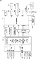
パチンコ遊技機1には、例えば、図2に示すような主基板11、演出制御基板12などといった、各種の制御基板が搭載されている。また、パチンコ遊技機1には、主基板11と演出制御基板12との間で伝送される各種の制御信号を中継するための中継基板15や、演出制御基板12と発光体制御基板16Cなどの各基板との間で伝送される各種信号を中継するための演出制御用中継基板16Aなども搭載されている。その他にも、パチンコ遊技機1における遊技盤などの背面には、例えば、払出制御基板、情報端子基板、発射制御基板、インタフェース基板、タッチセンサ基板などといった、各種の基板が配置されている。   The pachinko gaming machine 1 is equipped with various control boards such as a main board 11 and an effect control board 12 as shown in FIG. Further, the pachinko gaming machine 1 includes a relay board 15 for relaying various control signals transmitted between the main board 11 and the effect control board 12, and the effect control board 12 and the light emitter control board 16C. A production control relay board 16A for relaying various signals transmitted to and from each board is also mounted. In addition, various boards such as a payout control board, an information terminal board, a launch control board, an interface board, and a touch sensor board are arranged on the back surface of the game board or the like of the pachinko gaming machine 1.

主基板11には、プログラムに従ってパチンコ遊技機1を制御する遊技制御用マイクロコンピュータ100が搭載されている。遊技制御用マイクロコンピュータ100は、ゲーム制御(遊技進行制御)用のプログラム等を記憶するROM101、ワークメモリとして使用される記憶手段としてのRAM102、プログラムに従って制御動作を行うCPU103、I/Oポート部105、およびパラレルデータ信号をシリアルデータ信号に変換して出力する図示しないシリアル出力回路78を含む。この実施の形態では、ROM101およびRAM102は遊技制御用マイクロコンピュータ100に内蔵されている。すなわち、遊技制御用マイクロコンピュータ100は、1チップマイクロコンピュータである。1チップマイクロコンピュータには、少なくともCPU103のほかRAM102が内蔵されていればよく、ROM101は外付けであっても内蔵されていてもよい。また、I/Oポート部105は、外付けであってもよい。   A game control microcomputer 100 for controlling the pachinko gaming machine 1 according to a program is mounted on the main board 11. The game control microcomputer 100 includes a ROM 101 for storing programs for game control (game progress control), a RAM 102 as a storage unit used as a work memory, a CPU 103 for performing control operations according to the programs, and an I/O port unit 105. , And a serial output circuit 78 (not shown) that converts a parallel data signal into a serial data signal and outputs the serial data signal. In this embodiment, the ROM 101 and the RAM 102 are built in the game control microcomputer 100. That is, the game control microcomputer 100 is a one-chip microcomputer. The 1-chip microcomputer only needs to include at least the RAM 103 in addition to the CPU 103, and the ROM 101 may be external or internal. Further, the I/O port unit 105 may be externally attached.

遊技制御用マイクロコンピュータ100には、さらに、ハードウェア乱数を発生する乱数回路が内蔵されている。なお、遊技制御用マイクロコンピュータ100においてCPU103がROM101に格納されているプログラムに従って制御を実行するので、以下、遊技制御用マイクロコンピュータ100(またはCPU103)が実行する(または、処理を行う)ということは、具体的には、CPU103がプログラムに従って制御を実行することである。このことは、主基板11以外の他の基板に搭載されているマイクロコンピュータについても同様である。   The game control microcomputer 100 further includes a random number circuit that generates a hardware random number. Since the CPU 103 in the game control microcomputer 100 executes control in accordance with the program stored in the ROM 101, the following description means that the game control microcomputer 100 (or the CPU 103) executes (or performs processing). Specifically, the CPU 103 executes control according to a program. This also applies to the microcomputers mounted on other substrates than the main substrate 11.

また、ゲートスイッチ21、第1始動口スイッチ22A、第2始動口スイッチ22B、カウントスイッチ23などからの検出信号を遊技制御用マイクロコンピュータ100に与えるスイッチ回路110も主基板11に搭載されている。また、普通可変入賞球装置6Bを開閉するソレノイド27、および大入賞口を形成する特別可変入賞球装置7を開閉するソレノイド28を遊技制御用マイクロコンピュータ100からの指令に従って駆動するソレノイド回路111も主基板11に搭載されている。   Further, a switch circuit 110 for providing the game control microcomputer 100 with detection signals from the gate switch 21, the first starting opening switch 22A, the second starting opening switch 22B, the count switch 23, etc. is also mounted on the main board 11. Also, the solenoid circuit 111 that drives the solenoid 27 that opens and closes the normal variable winning ball device 6B and the solenoid 28 that opens and closes the special variable winning ball device 7 that forms the special winning opening in accordance with a command from the game control microcomputer 100 is mainly used. It is mounted on the substrate 11.

また、遊技制御用マイクロコンピュータ100は、特別図柄を可変表示する第1特別図柄表示装置4A、第2特別図柄表示装置4B、普通図柄を可変表示する普通図柄表示器20など(第1保留表示器25Aや第2保留表示器25Bなどの各保留表示器も含む)の表示制御を行う。また、遊技制御用マイクロコンピュータ100が搭載するシリアル出力回路78(図示せず)は、シフトレジスタなどによって構成され、CPU103が出力する演出制御コマンドをシリアルデータ信号に変換して、中継基板15を介して演出制御基板12に送信する。また、シリアル出力回路78は、CPU103が出力する制御信号をシリアルデータ信号に変換して第1特別図柄表示装置4A、第2特別図柄表示装置4B、普通図柄表示器20などに出力する。第1特別図柄表示装置4A、第2特別図柄表示装置4B、普通図柄表示器20などには、シリアルデータ信号をパラレルデータ信号に変換するシリアル−パラレル変換ICがそれぞれ設けられ、制御信号をパラレルデータ信号に変換して、第1特別図柄表示装置4A、第2特別図柄表示装置4B、普通図柄表示器20などに供給する。なお、 主基板11には、大当り遊技状態の発生を示す大当り情報等の情報出力信号をホールコンピュータ等の外部装置に対して出力する情報出力回路(図示せず)も搭載されている。   Further, the game control microcomputer 100, the first special symbol display device 4A, the second special symbol display device 4B that variably displays the special symbol, the normal symbol display device 20 that variably displays the normal symbol, etc. (the first reserved display device). Display control of each hold display device such as 25A and the second hold display device 25B). A serial output circuit 78 (not shown) mounted on the game control microcomputer 100 is composed of a shift register or the like, converts the effect control command output by the CPU 103 into a serial data signal, and transfers the serial data signal via the relay board 15. And sends it to the performance control board 12. Further, the serial output circuit 78 converts the control signal output by the CPU 103 into a serial data signal and outputs the serial data signal to the first special symbol display device 4A, the second special symbol display device 4B, the normal symbol display device 20, and the like. The first special symbol display device 4A, the second special symbol display device 4B, the normal symbol display 20, etc. are provided with serial-parallel conversion ICs for converting serial data signals into parallel data signals, respectively, and control signals are parallel data. It is converted into a signal and supplied to the first special symbol display device 4A, the second special symbol display device 4B, the ordinary symbol display device 20, and the like. The main board 11 is also equipped with an information output circuit (not shown) that outputs an information output signal such as big hit information indicating occurrence of a big hit game state to an external device such as a hall computer.

この実施の形態では、演出制御基板12に搭載されている制御装置(演出制御用マイクロコンピュータで構成される。)が、中継基板15を介して遊技制御用マイクロコンピュータ100からの演出制御コマンドをシリアルデータ方式として(すなわち、シリアル通信を用いて)受信し、飾り図柄を可変表示するなどの画像表示装置5の表示制御を行う。 また、演出制御基板12に搭載されている制御装置が、上述の演出制御コマンドに基づいて、スピーカ8L、8Rからの音出力の制御を行う。また、演出制御基板12に搭載されている制御装置は、上述の演出制御コマンドに基づいて、各可動部材(図示せず)を駆動するモータの駆動制御を行う。また、演出制御基板12は、演出制御用中継基板16Aを介して発光体制御基板16Cや第4図柄制御基板16Bなどに制御信号を送信し、例えば遊技盤2に設けられている遊技効果ランプ9の各LEDや、枠側に設けられているランプの各LED、大入賞口扉用LED197や第4図柄用LED191などの発光部品を含めた演出用の電気部品を制御する。なお、図2に示す例では、理解を容易にするため、遊技盤2に設けられている遊技効果ランプ9の各LEDや、枠側に設けられているランプの各LED、大入賞口扉用LED197などの発光部品をまとめて発光体ユニット71として示している。なお、演出制御用中継基板16Aと発光体制御基板16Cや第4図柄制御基板16Bは、ハーネスの両端に設けられたコネクタ(プラグ)がそれぞれの基板に挿入されることで物理的および電気的に接続されている。ハーネスは、多数の配線ケーブルを結束して構成されたものであればよい。   In this embodiment, the control device (which is composed of the effect control microcomputer) mounted on the effect control board 12 serializes the effect control command from the game control microcomputer 100 via the relay board 15. It receives as a data system (that is, using serial communication) and performs display control of the image display device 5 such as variably displaying a decorative pattern. Further, the control device mounted on the effect control board 12 controls the sound output from the speakers 8L and 8R based on the effect control command described above. Further, the control device mounted on the effect control board 12 performs drive control of the motor that drives each movable member (not shown) based on the effect control command described above. In addition, the production control board 12 transmits a control signal to the light emitter control board 16C, the fourth symbol control board 16B, etc. via the production control relay board 16A, and for example, the game effect lamp 9 provided on the game board 2. Each of the LEDs, each LED of the lamp provided on the frame side, the electrical components for production including the light emitting components such as the special winning opening door LED 197 and the fourth symbol LED 191 are controlled. In the example shown in FIG. 2, for easy understanding, each LED of the game effect lamp 9 provided on the game board 2, each LED of the lamp provided on the frame side, and the special winning opening door Light emitting components such as the LED 197 are collectively shown as a light emitter unit 71. The production control relay board 16A, the light emitter control board 16C, and the fourth symbol control board 16B are physically and electrically connected by inserting connectors (plugs) provided at both ends of the harness into the respective boards. It is connected. The harness may be configured by binding a large number of wiring cables.

また、演出制御基板12には、スティックコントローラ31Aに対する遊技者の操作行為を検出したことを示す情報信号としての操作検出信号を、コントローラセンサユニット35Aから伝送するための配線や、プッシュボタン31Bに対する遊技者の操作行為を検出したことを示す情報信号としての操作検出信号を、プッシュセンサ35Bから伝送するための配線も接続されている。   In addition, on the effect control board 12, wiring for transmitting an operation detection signal as an information signal indicating that the player's operation on the stick controller 31A has been detected from the controller sensor unit 35A, and a game for the push button 31B. A wiring for transmitting an operation detection signal as an information signal indicating that an operation action of a person is detected from the push sensor 35B is also connected.

図3は演出制御基板12の構成例を示すブロック図である。なお、図3に示す例では、演出制御に関して演出制御基板12のみを設ける例を示しているが、ランプドライバ基板や音声出力基板などを設けてもよい。この場合、ランプドライバ基板や音声出力基板にマイクロコンピュータを搭載してもよい。   FIG. 3 is a block diagram showing a configuration example of the effect control board 12. Although the example shown in FIG. 3 shows an example in which only the effect control board 12 is provided for effect control, a lamp driver board, an audio output board, or the like may be provided. In this case, a microcomputer may be mounted on the lamp driver board or the audio output board.

図3に示すように、演出制御基板12は、演出制御用CPU123、RAM(図示せず)、シリアル出力回路353、シリアル入力回路354、クロック信号生成回路356を含む演出制御用マイクロコンピュータ120を搭載している。なお、RAMは外付けであってもよい。演出制御基板12において、演出制御用CPU123は、内蔵または外付けのROM(図示せず)に格納されたプログラムに従って動作し、シリアル入力回路112および入力ポート113を介して演出制御コマンドを受信する。この場合、シリアル入力回路112は、シリアルデータ方式として受信した演出制御コマンドをパラレルデータ信号に変換し出力する。また、演出制御用CPU123は、演出制御コマンドに基づいて、VDP(ビデオディスプレイプロセッサ)109に画像表示装置5の表示制御を行わせる。   As shown in FIG. 3, the production control board 12 has a production control microcomputer 120 including a production control CPU 123, a RAM (not shown), a serial output circuit 353, a serial input circuit 354, and a clock signal generation circuit 356. is doing. The RAM may be external. In the effect control board 12, the effect control CPU 123 operates according to a program stored in a built-in or external ROM (not shown), and receives effect control commands via the serial input circuit 112 and the input port 113. In this case, the serial input circuit 112 converts the effect control command received as the serial data method into a parallel data signal and outputs the parallel data signal. In addition, the effect control CPU 123 causes the VDP (video display processor) 109 to perform display control of the image display device 5 based on the effect control command.

この実施の形態では、演出制御用マイクロコンピュータ120と共動して画像表示装置5の表示制御を行うVDP109が演出制御基板12に搭載されている。VDP109は、演出制御用マイクロコンピュータ120とは独立したアドレス空間を有し、そこにVRAMをマッピングする。VRAMは、画像データを展開するためのバッファメモリである。そして、VDP109は、VRAM内の画像データを、フレームメモリを介して画像表示装置5に出力する。   In this embodiment, the VDP 109 that cooperates with the effect control microcomputer 120 to control the display of the image display device 5 is mounted on the effect control board 12. The VDP 109 has an address space independent of the effect control microcomputer 120, and maps the VRAM therein. VRAM is a buffer memory for expanding image data. Then, the VDP 109 outputs the image data in the VRAM to the image display device 5 via the frame memory.

演出制御用CPU123は、受信した演出制御コマンドに従ってCGROM(図示せず)から必要なデータを読み出すための指令をVDP109に出力する。CGROMは、画像表示装置5に表示されるキャラクタ画像データや動画像データ、具体的には、人物、文字、図形や記号等(飾り図柄を含む)、および背景画像のデータをあらかじめ格納しておくためのROMである。VDP109は、演出制御用CPU123の指令に応じて、CGROMから画像データを読み出す。そして、VDP109は、読み出した画像データに基づいて表示制御を実行する。また、演出制御用CPU123は、コントローラセンサユニット35Aやプッシュセンサ35Bからの検知信号に基づいて各種演出制御を行う。   The effect control CPU 123 outputs to the VDP 109 a command for reading out necessary data from a CGROM (not shown) in accordance with the received effect control command. The CGROM stores in advance character image data and moving image data displayed on the image display device 5, specifically, people, characters, figures and symbols (including decorative patterns), and background image data. ROM for this. The VDP 109 reads the image data from the CGROM according to a command from the effect control CPU 123. Then, the VDP 109 executes display control based on the read image data. In addition, the effect control CPU 123 performs various effect controls based on detection signals from the controller sensor unit 35A and the push sensor 35B.

中継基板15には、主基板11から入力された信号を演出制御基板12に向かう方向にしか通過させない(演出制御基板12から中継基板15への方向には信号を通過させない)信号方向規制手段としての単方向性回路(図示せず)が搭載されている。単方向性回路としては、例えばダイオードやトランジスタが使用される。   As signal direction restricting means that allows the signal input from the main board 11 to pass through the relay board 15 only in the direction toward the effect control board 12 (does not pass the signal in the direction from the effect control board 12 to the relay board 15). The unidirectional circuit (not shown) is mounted. As the unidirectional circuit, for example, a diode or a transistor is used.

さらに、演出制御用CPU123は、シリアル出力回路353を介して各種ランプを駆動する信号を出力する。シリアル出力回路353は、入力した各種ランプのLEDを駆動する信号(パラレルデータ信号)をシリアルデータ信号に変換して演出制御用中継基板16Aに出力する。また、演出制御用CPU123は、音声合成用IC173に対して音番号データを出力する。   Further, the effect control CPU 123 outputs signals for driving various lamps via the serial output circuit 353. The serial output circuit 353 converts the input signals (parallel data signals) for driving the LEDs of various lamps into serial data signals and outputs them to the effect control relay board 16A. In addition, the production control CPU 123 outputs the sound number data to the voice synthesis IC 173.

この実施の形態において、演出制御基板12に搭載された演出制御用マイクロコンピュータ120は、制御信号をシリアル通信によって演出装置に伝送するときに用いられるクロック信号を生成して、生成されたクロック信号を演出装置に送信する。このとき、演出制御用マイクロコンピュータ120は、クロック信号の波形が矩形波の波形よりも緩やかに信号が立ち上がる波形になるようにクロック信号を生成してもよい。   In this embodiment, the effect control microcomputer 120 mounted on the effect control board 12 generates a clock signal used when transmitting the control signal to the effect device by serial communication, and outputs the generated clock signal. Send to the rendering device. At this time, the effect control microcomputer 120 may generate the clock signal so that the waveform of the clock signal becomes a waveform in which the signal rises more gently than the rectangular waveform.

この実施の形態における「演出装置」は、遊技効果ランプ9の各LEDや、枠側に設けられているランプの各LED、大入賞口扉用LED197や第4図柄用LED191などの発光部品を含めた演出用の電気部品、スピーカ8L、8Rおよび各可動部材を駆動するモータのうちの少なくともいずれかである。   The "rendering device" in this embodiment includes each LED of the game effect lamp 9, each LED of the lamp provided on the frame side, the light emitting parts such as the special winning opening door LED 197 and the fourth symbol LED 191. And at least one of the electric components for performance, the speakers 8L and 8R, and the motor that drives each movable member.

クロック信号生成回路356は、たとえば、所定の周波数(たとえば、5MHz)の矩形波を発生させる回路である。所定の周波数は、パチンコ遊技機1に搭載されるLEDの個数に応じて設定される。クロック信号の周波数は、高くなるほど多くの情報の伝送が可能となり、通信速度が高くなる。また、パチンコ遊技機1に搭載されるLEDの個数が多くなるほど通信量が増加するため高い通信速度が要求される。すなわち、通信速度の要求値は、パチンコ遊技機1に搭載されるLEDの個数に依存する。したがって、所定の周波数は、通信速度がパチンコ遊技機1に搭載されるLEDの個数に応じた通信速度の要求値よりも高くなるように設定することが望ましい。また、 クロック信号生成回路356は、コンデンサおよび抵抗器のうちの少なくともいずれかを用いた回路にバンドパスフィルタ、ローパスフィルタあるいは積分回路等の各種回路を組み合わせて構成される。クロック信号生成回路356は、クロック信号を演出制御用中継基板16Aに送信する。   The clock signal generation circuit 356 is, for example, a circuit that generates a rectangular wave having a predetermined frequency (for example, 5 MHz). The predetermined frequency is set according to the number of LEDs mounted on the pachinko gaming machine 1. The higher the frequency of the clock signal, the more information can be transmitted, and the higher the communication speed. Further, as the number of LEDs mounted on the pachinko gaming machine 1 increases, the communication amount increases, so that a high communication speed is required. That is, the required value of the communication speed depends on the number of LEDs mounted on the pachinko gaming machine 1. Therefore, it is desirable that the predetermined frequency be set so that the communication speed becomes higher than the required value of the communication speed according to the number of LEDs mounted on the pachinko gaming machine 1. In addition, the clock signal generation circuit 356 is configured by combining a circuit using at least one of a capacitor and a resistor with various circuits such as a bandpass filter, a lowpass filter, and an integrating circuit. The clock signal generation circuit 356 transmits the clock signal to the effect control relay board 16A.

クロック信号生成回路356から送信されたクロック信号は、演出制御用中継基板16Aを経由して発光体制御基板16Cの各基板に搭載されたシリアル−パラレル変換ICや第4図柄基板などに供給される。   The clock signal transmitted from the clock signal generation circuit 356 is supplied to the serial-parallel conversion IC mounted on each board of the light emitter control board 16C, the fourth pattern board, etc. via the relay board 16A for effect control. ..

音声合成用IC173は、音番号データを入力すると、音番号データに応じた音声や効果音を発生し増幅回路175に出力する。増幅回路175は、音声合成用IC173の出力レベルを、ボリューム176で設定されている音量に応じたレベルに増幅した音声信号をスピーカ8L、8Rに出力する。音声データROM174には、音番号データに応じた制御データが格納されている。音番号データに応じた制御データは、所定期間(例えば飾り図柄の変動期間)における効果音または音声の出力態様を時系列的に示すデータの集まりである。   When the voice number data is input, the voice synthesizing IC 173 generates a voice or a sound effect corresponding to the voice number data and outputs it to the amplifier circuit 175. The amplifier circuit 175 amplifies the output level of the voice synthesizing IC 173 to a level corresponding to the volume set by the volume 176 and outputs the audio signal to the speakers 8L and 8R. The voice data ROM 174 stores control data according to the tone number data. The control data corresponding to the sound number data is a collection of data indicating the output mode of the sound effect or the sound in a predetermined period (for example, the variation period of the decorative pattern) in time series.

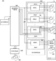
図4は、発光体制御基板16Cなどの構成例を示すブロック図である。演出制御基板12の演出制御用マイクロコンピュータ120は、制御信号を変換したシリアルデータ信号を、シリアルデータ線を経由して演出制御用中継基板16Aに送信するとともに、クロック信号を、クロック信号線を経由して演出制御用中継基板16Aに送信する。   FIG. 4 is a block diagram showing a configuration example of the light emitter control board 16C and the like. The production control microcomputer 120 of the production control board 12 transmits the serial data signal obtained by converting the control signal to the production control relay board 16A via the serial data line, and sends the clock signal via the clock signal line. And transmits it to the effect control relay board 16A.

発光体制御基板16Cは、ランプなどのLEDを点灯制御するための信号が送信される基板であり、図示するように基板A〜基板Fといった複数の基板の総称である。基板A〜基板Fは、それぞれがシリアル−パラレル変換IC(変換IC161〜166)を含んでおり、それぞれの基板は異なる位置に配置されている。シリアル−パラレル変換IC(変換IC161〜166)は、演出制御基板12から演出制御用中継基板16Aを介して送信されたシリアルデータ信号をパラレルデータ信号に変換するシリアル−パラレル変換ICである。   The light emitter control board 16C is a board to which a signal for controlling lighting of an LED such as a lamp is transmitted, and is a general term for a plurality of boards such as the boards A to F as illustrated. The substrates A to F each include a serial-parallel conversion IC (conversion ICs 161 to 166), and the respective substrates are arranged at different positions. The serial-parallel conversion ICs (conversion ICs 161 to 166) are serial-parallel conversion ICs that convert serial data signals transmitted from the performance control board 12 via the performance control relay board 16A into parallel data signals.

発光体制御基板16Cのそれぞれの基板(基板A〜基板F)は、演出制御用マイクロコンピュータ120から演出制御用中継基板16Aを介して入力したシリアルデータ信号およびクロック信号を、基板A〜基板Fのそれぞれに搭載された各変換IC161〜166に供給する。そして、各変換IC161〜166は、入力されたシリアルデータ信号をパラレルデータ信号に変換して、それぞれの基板に接続された各ランプのLED192〜197などにそれぞれ供給する。具体的に、この実施の形態では、基板A〜基板Eに搭載されている変換IC161〜165にて変換されたパラレルデータ信号は、それぞれの基板に接続されたLED192〜196に供給される。なお、基板Eに搭載されている変換IC165にて変換された複数のパラレルデータ信号のうちの一部(第4図柄用のパラレルデータ信号)は、パラレルデータ線を経由して演出制御用中継基板16Aに戻され、第4図柄基板16Bに送信される。そして、入力されたパラレルデータ信号は、第4図柄基板16Bに接続された第4図柄用LED191に供給される。また、基板Fに搭載されている変換IC166にて変換されたパラレルデータ信号は、発光体中継基板168を介して大入賞口扉用LED193に供給される。ここで、第4図柄基板16Bは、発光体制御基板16Cから接続するよりも演出制御用中継基板16Aから接続した方が短い配線で接続可能である。そのため、この実施の形態では、基板Eに搭載されている変換IC165にて変換された複数のパラレルデータ信号のうち、第4図柄用LED191に供給される(第4図柄用の)パラレルデータ信号が演出制御用中継基板16Aに送信されるように構成されている。また、基板Eに搭載されている変換IC165にてパラレルデータ信号に変換するため、第4図柄基板16Bに変換ICを搭載する必要がなく、コストを削減することができる。   Each of the boards (boards A to F) of the light emitter control board 16C receives the serial data signal and the clock signal input from the production control microcomputer 120 via the production control relay board 16A. It supplies to each conversion IC161-166 mounted in each. Then, the conversion ICs 161 to 166 convert the input serial data signals into parallel data signals and supply the parallel data signals to the LEDs 192 to 197 of the respective lamps connected to the respective substrates. Specifically, in this embodiment, the parallel data signals converted by the conversion ICs 161 to 165 mounted on the boards A to E are supplied to the LEDs 192 to 196 connected to the respective boards. A part of the plurality of parallel data signals converted by the conversion IC 165 mounted on the board E (parallel data signal for the fourth symbol) is a relay board for effect control via the parallel data line. It is returned to 16A and transmitted to the fourth design board 16B. Then, the input parallel data signal is supplied to the fourth symbol LED 191 connected to the fourth symbol substrate 16B. The parallel data signal converted by the conversion IC 166 mounted on the substrate F is supplied to the special winning opening door LED 193 via the light emitter relay substrate 168. Here, the fourth design board 16B can be connected with a shorter wiring when connected from the effect control relay board 16A than when connected from the light emitter control board 16C. Therefore, in this embodiment, among the plurality of parallel data signals converted by the conversion IC 165 mounted on the substrate E, the parallel data signal (for the fourth symbol) supplied to the LED 191 for the fourth symbol is the parallel data signal. It is configured to be transmitted to the effect control relay board 16A. Further, since the conversion IC 165 mounted on the board E converts into a parallel data signal, it is not necessary to mount the conversion IC on the fourth pattern board 16B, and the cost can be reduced.

演出制御用マイクロコンピュータ120は、主基板11に搭載されている遊技制御用マイクロコンピュータ100から上述した演出制御コマンドを受信すると、受信した演出制御コマンドの内容に応じて画像表示装置5の表示状態を変更したり、ランプの表示状態を変更したり、音番号データを出力したりするための制御信号を生成して、シリアルデータ信号に変換する。   When the effect control microcomputer 120 receives the above-described effect control command from the game control microcomputer 100 mounted on the main board 11, the effect control microcomputer 120 changes the display state of the image display device 5 according to the content of the received effect control command. A control signal for changing, changing the display state of the lamp, and outputting sound number data is generated and converted into a serial data signal.

この実施の形態では、各シリアル−パラレル変換IC(変換IC161〜166)には、あらかじめアドレスが付与されており、演出制御用マイクロコンピュータ120は、変換したシリアルデータ信号を送信する際に、シリアルデータ信号にアドレスを付加して出力する。各変換IC161〜166は、シリアルデータ信号を入力すると、入力したシリアルデータ信号に付加されているアドレスが自分のアドレスに合致するか否かを確認し、合致していればパラレルデータ信号に変換して各ランプのLEDなどに供給する(すなわち、出力する)。アドレスが合致していなければ各ランプのLEDへの供給は行わない。   In this embodiment, an address is given in advance to each serial-parallel conversion IC (conversion ICs 161 to 166), and the production control microcomputer 120 transmits the serial data when the converted serial data signal is transmitted. Add address to signal and output. When each of the conversion ICs 161 to 166 receives the serial data signal, the conversion ICs 161 to 166 check whether the address added to the input serial data signal matches its own address, and if they match, convert the parallel data signal into a parallel data signal. Supply (that is, output) to the LED or the like of each lamp. If the addresses do not match, the LED of each lamp is not supplied.

演出制御用マイクロコンピュータ120は、例えば、大当りが開始する内容の演出制御コマンドを受信し、遊技状態を大当り遊技状態となった場合において、大入賞口扉の開閉状態に応じて大入賞口扉用LED197を点灯させるように制御する。また、演出制御用マイクロコンピュータ120は、例えば、第4図柄の表示色を変化させることで特別図柄の変動・停止表示を表現する場合に、第4図柄用LED191の表示色を変化させることで特別図柄の変動・停止表示が表現されるよう制御する。   The effect control microcomputer 120 receives, for example, an effect control command of the content that the big hit starts, and when the game state becomes the big hit game state, for the big prize opening door, depending on the opening/closing state of the big prize opening door. The LED 197 is controlled to be turned on. Further, the effect control microcomputer 120, for example, when changing and stopping the display of the special symbol by changing the display color of the fourth symbol, by changing the display color of the LED 191 for the fourth symbol, It is controlled so that the fluctuation/stop display of the symbols is expressed.

図5は、演出制御用中継基板と発光体制御基板(図4の基板E)などの接続例を示す図である。図示するように、演出制御用中継基板16Aには、ハーネスHN1の一端に設けられたコネクタ(プラグ)を挿入することで、演出制御用中継基板16Aと発光体制御基板16Cとを物理的および電気的に接続するためのコネクタ(ソケット)Aが設けられている。発光体制御基板16Cには、ハーネスHN1の他端に設けられたコネクタ(プラグ)を挿入することで、演出制御用中継基板16Aと発光体制御基板16Cとを物理的および電気的に接続するためのコネクタ(ソケット)が設けられている。ハーネスHN1は、多数の配線ケーブルを結束して構成されたものであればよい。演出制御用中継基板16Aに設けられたコネクタAは、端子TM01〜TM12を備えている。発光体制御基板16Cに設けられたコネクタは、端子TN01〜TN12を備えている。演出制御用中継基板16AのコネクタAが備える端子TM01〜TM12と、発光体制御基板16Cのコネクタが備える端子TN01〜TN12は、両コネクタにハーネスHN1が取り付けられた場合に、それぞれ対応する番号の端子(例えば端子TM01と端子TN01)が物理的および電気的に接続される関係であればよい。   FIG. 5 is a diagram showing a connection example of the effect control relay board and the light emitter control board (the board E in FIG. 4). As shown in the figure, by inserting a connector (plug) provided at one end of the harness HN1 into the effect control relay board 16A, the effect control relay board 16A and the light emitter control board 16C are physically and electrically connected. A connector (socket) A for electrically connecting is provided. To insert a connector (plug) provided at the other end of the harness HN1 into the light emitter control board 16C to physically and electrically connect the effect control relay board 16A and the light emitter control board 16C. Connector (socket) is provided. The harness HN1 may be configured by binding a large number of wiring cables. The connector A provided on the effect control relay board 16A includes terminals TM01 to TM12. The connector provided on the light emitter control board 16C includes terminals TN01 to TN12. The terminals TM01 to TM12 included in the connector A of the effect control relay board 16A and the terminals TN01 to TN12 included in the connector of the light emitter control board 16C respectively have terminals with corresponding numbers when the harness HN1 is attached to both connectors. The relationship (for example, the terminal TM01 and the terminal TN01) may be physically and electrically connected.

また、図5に示すように、演出制御用中継基板16Aには、ハーネスHN2の一端に設けられたコネクタ(プラグ)を挿入することで、演出制御用中継基板16Aと第4図柄基板16Bとを物理的および電気的に接続するためのコネクタ(ソケット)Bが設けられている。第4図柄基板16Bには、ハーネスHN2の他端に設けられたコネクタ(プラグ)を挿入することで、演出制御用中継基板16Aと第4図柄基板16Bとを物理的および電気的に接続するためのコネクタ(ソケット)が設けられている。ハーネスHN2は、多数の配線ケーブルを結束して構成されたものであればよい。演出制御用中継基板16Aに設けられたコネクタBは、端子TL01〜TL04を備えている。第4図柄基板16Bに設けられたコネクタは、端子TG01〜TG04を備えている。演出制御用中継基板16AのコネクタBが備える端子TL01〜TL04と、第4図柄基板16Bのコネクタが備える端子TG01〜TG04は、両コネクタにハーネスHN2が取り付けられた場合に、それぞれ対応する番号の端子(例えば端子TL01と端子TG01)が物理的および電気的に接続される関係であればよい。   As shown in FIG. 5, the effect control relay board 16A and the fourth symbol board 16B are inserted into the effect control relay board 16A by inserting a connector (plug) provided at one end of the harness HN2. A connector (socket) B for physically and electrically connecting is provided. By inserting a connector (plug) provided at the other end of the harness HN2 into the fourth design board 16B, to physically and electrically connect the effect control relay board 16A and the fourth design board 16B. Connector (socket) is provided. The harness HN2 may be configured by binding a large number of wiring cables. The connector B provided on the effect control relay board 16A includes terminals TL01 to TL04. The connector provided on the fourth pattern board 16B includes terminals TG01 to TG04. The terminals TL01 to TL04 included in the connector B of the effect control relay board 16A and the terminals TG01 to TG04 included in the connector of the fourth pattern board 16B are terminals of corresponding numbers when the harness HN2 is attached to both connectors. (For example, the terminal TL01 and the terminal TG01) may be connected physically and electrically.

演出制御用中継基板16AのコネクタAが備える端子TM01〜TM12には(発光体制御基板16Cのコネクタが備える端子TN01〜TN12についても同様)は、グランド(GND)やVSL(AC24Vを整流および平滑)、VDL(DC12V)、VCL(DC5V)といった、各種の電圧を提供可能とする端子が含まれている。また、端子TM01〜TM12には、発光体制御基板16Cにシリアルデータ信号(シリアル信号)やクロック信号を供給する端子や、パラレル信号方式で第4図柄用のパラレルデータ信号を受信するための端子などが含まれている。発光体制御基板16Cのコネクタが備える端子TN01〜TN12には、変換IC165にシリアルデータ信号(シリアル信号)やクロック信号を供給する端子や、パラレル信号方式で第4図柄用のパラレルデータ信号(パラレル信号)を送信するための端子などが含まれている。   The terminals TM01 to TM12 included in the connector A of the production control relay board 16A (the same applies to the terminals TN01 to TN12 included in the connector of the light emitter control board 16C) are ground (GND) and VSL (AC24V is rectified and smoothed). , VDL (DC12V), VCL (DC5V), and the like capable of providing various voltages. The terminals TM01 to TM12 are terminals for supplying a serial data signal (serial signal) and a clock signal to the light emitter control board 16C, a terminal for receiving a parallel data signal for the fourth symbol by a parallel signal system, and the like. It is included. Terminals TN01 to TN12 provided in the connector of the light emitter control board 16C are terminals for supplying serial data signals (serial signals) and clock signals to the conversion IC 165, and parallel data signals (parallel signals) for the fourth symbol by the parallel signal method. ) Is included, such as a terminal for sending.

演出制御用中継基板16AのコネクタBが備える端子TL01〜TL04には(第4図柄基板16Bのコネクタが備える端子TG01〜TG04についても同様)、VCL(DC5V)といった、電圧を提供可能とする端子(TL04、TG04)が含まれている。また、演出制御用中継基板16AのコネクタBが備える端子TL01〜TL04には、第4図柄基板16Bにパラレル信号を供給する端子(第4図柄基板16Bのコネクタが備える端子TG01〜TG04については第4図柄用LED191へ当該パラレル信号を供給する端子)が含まれている(TL01〜TL03、TG01〜TG03)。   Terminals TL01 to TL04 included in the connector B of the effect control relay board 16A (similarly to the terminals TG01 to TG04 included in the connector of the fourth pattern board 16B), terminals capable of providing a voltage such as VCL (DC5V) ( TL04, TG04) are included. Further, the terminals TL01 to TL04 included in the connector B of the effect control relay board 16A are terminals for supplying a parallel signal to the fourth symbol board 16B (the terminals TG01 to TG04 included in the connector of the fourth symbol board 16B are the fourth terminals. A terminal for supplying the parallel signal to the design LED 191) is included (TL01 to TL03, TG01 to TG03).

このように、演出制御用中継基板16AのコネクタAが備える端子を通じて発光体制御基板16Cにシリアル信号やクロック信号が供給され、当該信号が変換IC165にてパラレルデータ信号(パラレル信号)に変換される。そして、第4図柄用以外のパラレル信号については、そのまま各LEDに供給される一方で、第4図柄用のパラレル信号については発光体制御基板16Cのコネクタが備える端子を通じて、演出制御用中継基板16AのコネクタAが備える端子に供給される。供給されたパラレル信号は、演出制御用中継基板16AのコネクタAが備える端子から当該演出制御用中継基板16AのコネクタBが備える端子を通じて第4図柄基板16Bに供給され、第4図柄用LED191へ供給される。   In this way, the serial signal or the clock signal is supplied to the light emitter control board 16C through the terminal provided in the connector A of the effect control relay board 16A, and the signal is converted into the parallel data signal (parallel signal) by the conversion IC 165. .. Then, while the parallel signal other than for the fourth symbol is supplied to each LED as it is, for the parallel signal for the fourth symbol through the terminal provided in the connector of the light emitter control substrate 16C, the effect control relay substrate 16A Is supplied to the terminals of the connector A. The supplied parallel signal is supplied from the terminal provided in the connector A of the production control relay board 16A to the fourth design board 16B through the terminal provided in the connector B of the production control relay board 16A, and is supplied to the fourth design LED 191. To be done.

第4図柄用LED191へは、発光体制御基板16Cから接続するよりも演出制御用中継基板16Aから接続した方が短い配線で接続可能となるため、このように発光体制御基板16Cの変換IC165にて変換されたパラレル信号の一部を演出制御用中継基板16Aへ戻すことで配線の無駄を防止してシリアル−パラレル変換ICを効率的に利用することができる。   The LED 191 for the fourth design can be connected with a shorter wiring when connected from the effect control relay board 16A than when connected from the light emitter control board 16C, and thus in the conversion IC 165 of the light emitter control board 16C. By returning a part of the parallel signal thus converted to the effect control relay board 16A, it is possible to prevent waste of wiring and efficiently use the serial-parallel conversion IC.

また、発光体制御基板16Cの変換IC165にて変換されたパラレル信号の一部を、演出制御用中継基板16Aを介して第4図柄基板16Bに供給する。したがって、第4図柄基板16Bにシリアル−パラレル変換ICを設ける必要がなくコストを削減することができる。発光体制御基板16Cの変換IC165はシリアルデータ信号をパラレルデータ信号に変換するシリアル−パラレル変換ICであり、演出制御基板12から演出制御用中継基板16Aを介して送信されたシリアルデータ信号をパラレルデータ信号に変換する。したがって、発光体制御基板16Cに変換IC165を設けることで配線の長さを考慮しつつ効率よく変換手段を利用することができる。   Further, a part of the parallel signal converted by the conversion IC 165 of the light emitter control board 16C is supplied to the fourth symbol board 16B via the effect control relay board 16A. Therefore, it is not necessary to provide the serial-parallel conversion IC on the fourth pattern board 16B, and the cost can be reduced. The conversion IC 165 of the light emitter control board 16C is a serial-parallel conversion IC that converts a serial data signal into a parallel data signal. The serial data signal transmitted from the effect control board 12 via the effect control relay board 16A is converted into parallel data. Convert to signal. Therefore, by providing the conversion IC 165 on the light emitter control board 16C, the conversion means can be used efficiently while considering the length of the wiring.

発光体制御基板16Cの変換IC165にて変換された複数のパラレル信号のうち、第4図柄用のパラレル信号についてのみ演出制御用中継基板16Aを介して第4図柄基板16Bに供給される。したがって、発光体制御基板16Cにてまとめて変換するため演出制御用中継基板16Aに別途シリアル−パラレル変換ICを設ける必要がなくコストを削減することができる。   Of the plurality of parallel signals converted by the conversion IC 165 of the light emitter control board 16C, only the parallel signal for the fourth symbol is supplied to the fourth symbol board 16B via the effect control relay substrate 16A. Therefore, since conversion is performed collectively by the light emitter control board 16C, it is not necessary to separately provide a serial-parallel conversion IC on the effect control relay board 16A, and the cost can be reduced.

演出制御用中継基板16Aは、発光体制御基板16Cにシリアル信号を送信する一方で、第4図柄基板16Bにはパラレル信号のみを送信する。したがって不要な信号を出力することがなくコストを削減することができる。また、発光体制御基板16Cにはシリアル−パラレル変換ICである変換IC165を備える一方で、第4図柄基板16Bにはシリアル−パラレル変換ICを備えない。したがって、不要な変換ICを備える必要がなくコストを削減することができる。   The production control relay board 16A transmits a serial signal to the light emitter control board 16C, while transmitting only a parallel signal to the fourth pattern board 16B. Therefore, the cost can be reduced without outputting an unnecessary signal. Further, the light emitter control board 16C is provided with a conversion IC 165 which is a serial-parallel conversion IC, while the fourth design board 16B is not provided with a serial-parallel conversion IC. Therefore, it is not necessary to provide an unnecessary conversion IC, and the cost can be reduced.

なお、この発明は、上記実施の形態に限定されず、様々な変形及び応用が可能である。例えば、パチンコ遊技機1では、上記実施の形態で示した全ての技術的特徴を備えるものでなくてもよく、従来技術における少なくとも1つの課題を解決できるように、上記実施の形態で説明した一部の構成を備えたものであってもよい。   The present invention is not limited to the above-mentioned embodiment, and various modifications and applications are possible. For example, the pachinko gaming machine 1 does not have to have all the technical features shown in the above-mentioned embodiment, and one described in the above-described embodiment can solve at least one problem in the conventional technology. It may have a partial structure.

上記実施の形態では、発光体制御基板16Cの変換IC165にて変換された複数のパラレル信号のうち、第4図柄用のパラレル信号についてのみ演出制御用中継基板16Aに送信する例を示したが、これは一例である。第4図柄用のパラレル信号の他にも、発光体制御基板16Cから接続するよりも演出制御用中継基板16Aから接続した方が短い配線で接続可能となるものについては演出制御用中継基板16Aに送信してもよい(戻してもよい)。ただし、演出制御用中継基板16Aに送信するパラレル信号の数は、発光体制御基板16Cの変換IC165にて変換されたパラレル信号の数の半数以下となることが望ましい。これによれば、発光体制御基板16Cの変換IC165にてまとめて変換するため演出制御用中継基板16Aに別途変換ICを設ける必要がなくコストを削減することができる。また、配線の長さを考慮しつつ効率よく変換手段を利用することができる。   In the above embodiment, an example is shown in which only the parallel signal for the fourth symbol is transmitted to the effect control relay board 16A among the plurality of parallel signals converted by the conversion IC 165 of the light emitter control board 16C, This is an example. In addition to the parallel signal for the fourth symbol, the connection from the effect control relay board 16A is shorter than the connection from the light emitter control board 16C. May be sent (may be returned). However, it is desirable that the number of parallel signals transmitted to the effect control relay board 16A be equal to or less than half of the number of parallel signals converted by the conversion IC 165 of the light emitter control board 16C. According to this, since conversion is collectively performed by the conversion IC 165 of the light emitter control board 16C, it is not necessary to separately provide a conversion IC on the effect control relay board 16A, and the cost can be reduced. Further, the conversion means can be efficiently used while considering the length of the wiring.

また、上記実施の形態では、基板Eの変換IC165にて変換されたパラレル信号の一部を演出制御用中継基板16Aに送信する(戻す)例を示したが、基板Eの他の基板(例えば基板Aなど)の変換ICにて変換されたパラレル信号の一部を演出制御用中継基板16Aに送信する(戻す)ようにしてもよい。なお、基板Eの場合と同様に、当該変換ICにて変換を行った基板から接続するよりも演出制御用中継基板16Aから接続した方が短い配線で接続可能となるものであることが前提となる。これによれば、必要箇所に必要な長さの配線にて接続を行うことが可能となり、シリアル−パラレル変換ICをより効率的に利用することができる。   Further, in the above embodiment, an example of transmitting (returning) a part of the parallel signal converted by the conversion IC 165 of the board E to the effect control relay board 16A is shown, but another board of the board E (for example, A part of the parallel signal converted by the conversion IC of the board A or the like) may be transmitted (returned) to the effect control relay board 16A. As in the case of the board E, it is premised that the connection from the effect control relay board 16A is shorter than the connection from the board converted by the conversion IC. Become. According to this, it becomes possible to connect to a required place with the wiring of required length, and it is possible to use the serial-parallel conversion IC more efficiently.

また、上記実施の形態では、それぞれ異なる位置に配置された基板A〜基板Fの総称としての発光体制御基板16Cに送信されたシリアル信号をそれぞれの基板に搭載された変換ICにてパラレル信号に変換し、その一部を演出制御用中継基板16Aに送信する例を示したが、これは一例である。この他にも、複数設けられた可動部材のそれぞれを駆動する複数のモータに駆動制御の信号を送信する可動部材制御基板に搭載された変換ICにてパラレル信号に変換し、その一部を演出制御用中継基板16Aに送信してもよい。この場合、上記実施の形態と同様に、演出制御用中継基板16Aから接続した方が短い配線で接続可能となる対象の信号を演出制御用中継基板16Aに送信することを前提とする。すなわち、ランプなどLEDの点灯制御に関するパラレルデータ信号だけでなく、例えば可動部材などの駆動制御に関するパラレルデータ信号などといったその他の信号についても、演出制御用中継基板16Aから接続した方が短い配線で接続可能となる場合には、一旦シリアルデータ信号からパラレルデータ信号に変換した後に演出制御用中継基板16Aに送信するようにしてもよい。これによれば、必要箇所に必要な長さの配線にて接続を行うことが可能となり、シリアル−パラレル変換ICをより効率的に利用することができる。   Further, in the above-described embodiment, the serial signals transmitted to the light emitter control board 16C, which is a generic term for the boards A to F arranged at different positions, are converted into parallel signals by the conversion ICs mounted on the boards. An example in which the conversion is performed and a part of the conversion is transmitted to the effect control relay board 16A is shown, but this is an example. In addition to this, a conversion IC mounted on a movable member control board that transmits a drive control signal to a plurality of motors that drive each of a plurality of movable members is converted into parallel signals, and a part of them is produced. It may be transmitted to the control relay board 16A. In this case, similar to the above-described embodiment, it is premised that a target signal that can be connected with shorter wiring when connected from the effect control relay board 16A is transmitted to the effect control relay board 16A. That is, not only the parallel data signal relating to the lighting control of the LED such as a lamp, but also other signals such as the parallel data signal relating to the drive control of the movable member, etc. are connected by the wiring for which the relay board 16A for effect control is shorter. If possible, the serial data signal may be once converted into a parallel data signal and then transmitted to the effect control relay board 16A. According to this, it becomes possible to connect to a required place with wiring of a required length, and the serial-parallel conversion IC can be used more efficiently.

上記実施の形態では、第1始動入賞口を通過(進入)した遊技球の検出に基づいて第1特図を用いた特図ゲームが実行され、第2始動入賞口を通過(進入)した遊技球の検出に基づいて第2特図を用いた特図ゲームが実行されるものとして説明した。しかしながら、この発明はこれに限定されず、第1始動入賞口と第2始動入賞口のいずれを遊技球が通過(進入)したかにかかわらず共通の特別図柄を用いた特図ゲームが実行されるものであってもよい。   In the above embodiment, the special drawing game using the first special map is executed based on the detection of the game ball that has passed (entered) the first starting winning opening, and the game that has passed (entering) the second starting winning opening. The special figure game using the second special figure is executed based on the detection of a sphere. However, the present invention is not limited to this, and a special drawing game using a common special symbol is executed regardless of which of the first starting winning opening and the second starting winning opening the game ball passes (enters). It may be one.

なお、上記実施形態では、0〜9の数字または記号等の複数種類の特別図柄を可変表示させ表示結果を導出表示させる態様を示したが、可変表示は、そのような態様に限定されない。例えば、可変表示させる特別図柄と、可変表示結果として導出表示される特別図柄とが異なっていてもよい。換言すれば、変動する複数種類の特別図柄に含まれない特別図柄が可変表示結果として導出表示されてもよいし、変動する複数種類の特別図柄の中には可変表示結果として特別導出表示されないものが含まれていてもよい。また、必ずしも複数種類の特別図柄を可変表示させる必要はなく、1種類の特別図柄のみを用いて可変表示を実行する態様であってもよい。1種類の特別図柄を用いた可変表示として、例えば、当該1種類の特別図柄を点滅させてもよい(交互に点灯/消灯を繰返してもよい)。即ち、点灯、消灯の繰返しを可変表示としてもよい。そして、この場合であっても、当該1種類の特別図柄が最後に導出表示(点灯)されるものであってもよいし、当該1種類の図柄とは異なる図柄が最後に導出表示されるものであってもよい。また、他の図柄(例えば、普通図柄、飾り図柄等)の可変表示についても同様である。   In the above embodiment, a mode in which a plurality of types of special symbols such as numbers 0 to 9 or symbols are variably displayed and the display result is derived and displayed is shown, but the variable display is not limited to such a mode. For example, the special symbol that is variably displayed may be different from the special symbol that is derived and displayed as the variable display result. In other words, special symbols that are not included in the changing plural types of special symbols may be displayed as a variable display result, or may not be specially derived and displayed as a variable display result among the changing plural types of special symbols. May be included. Further, it is not always necessary to variably display a plurality of types of special symbols, and a mode in which the variable display is executed using only one type of special symbol may be adopted. As a variable display using one kind of special symbol, for example, the one kind of special symbol may be blinked (lighting/lighting off may be alternately repeated). That is, the variable display may be repeated lighting and extinguishing. And, even in this case, the special symbol of the one type may be displayed (lit) at the end, or the symbol different from the one type may be displayed at the end. May be The same applies to the variable display of other symbols (for example, ordinary symbols, decorative symbols, etc.).

その他にも、パチンコ遊技機1の装置構成、データ構成、画像表示装置5の表示領域における演出画像の表示動作を含めた各種の演出動作などは、本発明の趣旨を逸脱しない範囲で、任意に変更および修正が可能である。また、本発明の遊技機は、入賞の発生に基づいて所定数の遊技媒体を景品として払い出す払出式遊技機に限定されるものではなく、遊技媒体を封入し入賞の発生に基づいて得点を付与する封入式遊技機にも適用することができる。例えば、プリペイドカードや会員カード等の遊技用記録媒体の記録情報より特定される大きさの遊技価値である度数を使用して、遊技に使用するための遊技得点を付与するとともに、付与された遊技得点又は遊技による入賞により付与された遊技得点を使用して遊技機内に封入された遊技球を遊技領域に打ち込んで遊技者が遊技を行う遊技機にも本発明を適用することができる。さらには遊技用価値を用いて1ゲームに対して所定数の賭数を設定することによりゲームが開始可能となるとともに、各々が識別可能な複数種類の識別情報を変動表示可能な可変表示装置に表示結果が導出されることにより1ゲームが終了し、可変表示装置で導出された表示結果に応じて入賞が発生可能とされたスロットマシンにも適用することができる。   In addition, the device configuration of the pachinko gaming machine 1, the data configuration, various production operations including the display operation of the production image in the display area of the image display device 5, and the like are arbitrarily performed without departing from the spirit of the present invention. Changes and modifications are possible. Further, the gaming machine of the present invention is not limited to a pay-out type gaming machine that pays out a predetermined number of game media as a prize based on the occurrence of a prize, and encloses the game medium to score points based on the occurrence of a prize. It can also be applied to an enclosed game machine to be given. For example, by using a frequency that is a game value of a size specified by the recorded information of a game recording medium such as a prepaid card or a membership card, a game score for use in a game is given and the given game is given. The present invention can also be applied to a gaming machine in which a player plays a game by hitting a game ball enclosed in the gaming machine into a game area by using a score or a game score given by a prize for a game. Further, the game can be started by setting a predetermined number of bets for one game by using the gaming value, and a variable display device capable of variably displaying a plurality of types of identification information that can be respectively identified. One game is completed by deriving the display result, and the present invention can be applied to a slot machine in which a prize can be generated according to the display result derived by the variable display device.

即ち、遊技領域に設けられた始動領域を遊技媒体が通過したことに基づいて、各々が識別可能な複数種類の識別情報の可変表示を行い表示結果を導出表示する可変表示手段を備え、当該可変表示手段に予め定められた特定表示結果が導出表示されたときに、遊技者にとって有利な特定遊技状態に制御する遊技機であるが、遊技得点が0でないときに遊技得点を使用して遊技機内に封入された遊技球を遊技領域に打ち込んで遊技が行われ、遊技球の打ち込みに応じて遊技得点を減算し、遊技領域に設けられた入賞領域に遊技球が入賞することに応じて遊技得点を加算する遊技機にも本発明を適用できる。そのような遊技機は、遊技得点の加算に使用可能な遊技用価値の大きさを特定可能な情報が記録された遊技用記録媒体を挿入するための遊技用記録媒体挿入口と、遊技用記録媒体挿入口に挿入された遊技用記録媒体に記録されている記録情報の読み出しを行う遊技用記録媒体処理手段を備えていてもよい。   That is, based on the fact that the game medium has passed through the starting area provided in the game area, a variable display means is provided for variably displaying a plurality of types of identification information that can be identified, and deriving and displaying the display result. This is a gaming machine that controls to a specific gaming state that is advantageous to the player when a predetermined specific display result is derived and displayed on the display means. However, when the gaming score is not 0, the gaming score is used in the gaming machine. A game is played by hitting the game ball enclosed in the game area, the game score is subtracted according to the hitting of the game ball, and the game score is awarded when the game ball wins the prize area provided in the game area. The present invention can be applied to a gaming machine that adds. Such a game machine has a game recording medium insertion slot for inserting a game recording medium in which information capable of specifying the magnitude of the game value that can be used for adding game points is recorded, and a game recording medium. A game recording medium processing means for reading the record information recorded in the game recording medium inserted in the medium insertion opening may be provided.

また、特別図柄の可変表示中に表示されるものは1種類の外れ図柄(例えば、「−」を示す記号)だけで、当該図柄の表示と消灯とを繰り返すことによって可変表示を行うようにしてもよい。さらに可変表示中に当該図柄が表示されるものも、可変表示の停止時には、当該図柄が表示されなくてもよい(表示結果としては「−」を示す記号が表示されなくてもよい)。   Moreover, what is displayed in the variable display of the special symbol is only one type of deviating symbol (for example, a symbol indicating "-"), and the variable display is performed by repeatedly displaying and extinguishing the symbol. Good. Further, even when the symbol is displayed during the variable display, the symbol may not be displayed when the variable display is stopped (the symbol indicating "-" may not be displayed as the display result).

本発明を実現するためのプログラム及びデータは、パチンコ遊技機1に含まれるコンピュータ装置などに対して、着脱自在の記録媒体により配布・提供される形態に限定されるものではなく、予めコンピュータ装置などの有する記憶装置にプリインストールしておくことで配布される形態を採っても構わない。さらに、本発明を実現するためのプログラム及びデータは、通信処理部を設けておくことにより、通信回線等を介して接続されたネットワーク上の、他の機器からダウンロードすることによって配布する形態を採っても構わない。   The program and data for realizing the present invention are not limited to the form distributed and provided to a computer device included in the pachinko gaming machine 1 by a removable recording medium, and the computer device or the like in advance. It may be distributed by being pre-installed in the storage device included in. Further, the program and data for implementing the present invention may be distributed by being downloaded from another device on a network connected via a communication line or the like by providing a communication processing unit. It doesn't matter.

そして、ゲームの実行形態も、着脱自在の記録媒体を装着することにより実行するものだけではなく、通信回線等を介してダウンロードしたプログラム及びデータを、内部メモリ等に一旦格納することにより実行可能とする形態、通信回線等を介して接続されたネットワーク上における、他の機器側のハードウェア資源を用いて直接実行する形態としてもよい。さらには、他のコンピュータ装置等とネットワークを介してデータの交換を行うことによりゲームを実行するような形態とすることもできる。   The game execution mode is not limited to that executed by mounting a removable recording medium, but can also be executed by temporarily storing the program and data downloaded via a communication line in the internal memory or the like. Alternatively, the hardware resources of other devices may be directly used on the network connected via a communication line. Furthermore, the game may be executed by exchanging data with another computer device or the like via a network.

1 パチンコ遊技機
2 遊技盤
3 遊技機用枠
4A 第1特別図柄表示装置
4B 第2特別図柄表示装置
5 画像表示装置
5H 始動入賞記憶表示エリア
6A 普通入賞球装置
6B 普通可変入賞球装置
7 特別可変入賞球装置
8 スピーカ
9 遊技効果ランプ
11 主基板
12 演出制御基板
15 中継基板
16A 演出制御用中継基板
16B 第4図柄基板
16C 発光体制御基板
20 普通図柄表示器
21 ゲートスイッチ
22A 第1始動口スイッチ
22B 第2始動口スイッチ
23 カウントスイッチ
100 遊技制御用マイクロコンピュータ
101 ROM
102 RAM
103 CPU
104 乱数回路
105 I/O
120 演出制御用マイクロコンピュータ
161〜166 基板A〜基板F
168 発光体中継基板
191 第4図柄用LED
197 大入賞口扉用LED
1 Pachinko gaming machine 2 Gaming board 3 Frame for gaming machine 4A First special symbol display device 4B Second special symbol display device 5 Image display device 5H Start winning prize memory display area 6A Normal winning ball device 6B Normal variable winning ball device 7 Special variable Prize winning ball device 8 Speaker 9 Game effect lamp 11 Main board 12 Production control board 15 Relay board 16A Production control relay board 16B Fourth design board 16C Light emitter control board 20 Normal design display 21 Gate switch 22A First start opening switch 22B Second start opening switch 23 Count switch 100 Game control microcomputer 101 ROM
102 RAM
103 CPU
104 random number circuit 105 I/O
120 Production Control Microcomputers 161 to 166 Board A to Board F
168 Light emitter relay substrate 191 Fourth LED for design
197 LED for award winning door

Claims (1)

遊技を行う遊技機であって、
第1基板と、
前記第1基板に従属する第2基板と、を備え、
前記第2基板は、前記第1基板から出力された第1信号を前記第1信号とは異なる第2信号へ変換する変換手段を備え、前記変換手段で変換された前記第2信号の一部を前記第1基板へ出力し、
前記変換手段は、前記第1信号を複数の前記第2信号へ変換し、
前記第1基板へ出力する前記第2信号の数を、前記変換手段で変換された前記第2信号の数の半数以下とする、
ことを特徴とする遊技機。
A gaming machine for playing a game,
A first substrate,
A second substrate subordinate to the first substrate,
The second substrate includes a conversion unit that converts the first signal output from the first substrate into a second signal different from the first signal, and a part of the second signal converted by the conversion unit. To the first substrate,
The conversion means converts the first signal into a plurality of the second signals,
The number of the second signals output to the first substrate is less than or equal to half of the number of the second signals converted by the conversion means.
A gaming machine characterized by that.
JP2017105323A 2017-05-29 2017-05-29 Amusement machine Active JP6701123B2 (en)

Priority Applications (1)

Application Number Priority Date Filing Date Title
JP2017105323A JP6701123B2 (en) 2017-05-29 2017-05-29 Amusement machine

Applications Claiming Priority (1)

Application Number Priority Date Filing Date Title
JP2017105323A JP6701123B2 (en) 2017-05-29 2017-05-29 Amusement machine

Publications (3)

Publication Number Publication Date
JP2018198825A JP2018198825A (en) 2018-12-20
JP2018198825A5 JP2018198825A5 (en) 2019-08-08
JP6701123B2 true JP6701123B2 (en) 2020-05-27

Family

ID=64667476

Family Applications (1)

Application Number Title Priority Date Filing Date
JP2017105323A Active JP6701123B2 (en) 2017-05-29 2017-05-29 Amusement machine

Country Status (1)

Country Link
JP (1) JP6701123B2 (en)

Also Published As

Publication number Publication date
JP2018198825A (en) 2018-12-20

Similar Documents

Publication Publication Date Title
EP2172252B1 (en) Hand-held information processing apparatus
JP6753877B2 (en) Game machine
JP2011234992A (en) Pachinko game machine
JP2017063852A (en) Game machine
JP6438066B2 (en) Game machine
JP6701123B2 (en) Amusement machine
JP2021029891A (en) Game machine
JP6572272B2 (en) Game machine
JP2003284819A (en) Game machine
JP7046864B2 (en) Pachinko machine
JPH05293245A (en) Game device
JP2021029890A (en) Game machine
JP7061593B2 (en) Pachinko machine
JP2004073581A (en) Game machine and game program
JP7200417B2 (en) game machine
JP3979438B2 (en) Game equipment
JP6753880B2 (en) Game machine
JP2022066534A (en) Game machine
JP6392284B2 (en) Game machine
JP4929525B2 (en) Game machine
JP2014223362A (en) Game machine
JP3915835B2 (en) Game equipment
JP3915833B2 (en) Game equipment
JP3915838B2 (en) Game equipment
JP3915837B2 (en) Game equipment

Legal Events

Date Code Title Description
A621 Written request for application examination

Free format text: JAPANESE INTERMEDIATE CODE: A621

Effective date: 20190124

A521 Request for written amendment filed

Free format text: JAPANESE INTERMEDIATE CODE: A523

Effective date: 20190627

A977 Report on retrieval

Free format text: JAPANESE INTERMEDIATE CODE: A971007

Effective date: 20190918

A131 Notification of reasons for refusal

Free format text: JAPANESE INTERMEDIATE CODE: A132

Effective date: 20190924

A521 Request for written amendment filed

Free format text: JAPANESE INTERMEDIATE CODE: A523

Effective date: 20191119

TRDD Decision of grant or rejection written
A01 Written decision to grant a patent or to grant a registration (utility model)

Free format text: JAPANESE INTERMEDIATE CODE: A01

Effective date: 20200421

A61 First payment of annual fees (during grant procedure)

Free format text: JAPANESE INTERMEDIATE CODE: A61

Effective date: 20200501

R150 Certificate of patent or registration of utility model

Ref document number: 6701123

Country of ref document: JP

Free format text: JAPANESE INTERMEDIATE CODE: R150

R250 Receipt of annual fees

Free format text: JAPANESE INTERMEDIATE CODE: R250

R250 Receipt of annual fees

Free format text: JAPANESE INTERMEDIATE CODE: R250