JP6700618B2 - Laminated body and manufacturing method thereof - Google Patents
Laminated body and manufacturing method thereof Download PDFInfo
- Publication number
- JP6700618B2 JP6700618B2 JP2017505010A JP2017505010A JP6700618B2 JP 6700618 B2 JP6700618 B2 JP 6700618B2 JP 2017505010 A JP2017505010 A JP 2017505010A JP 2017505010 A JP2017505010 A JP 2017505010A JP 6700618 B2 JP6700618 B2 JP 6700618B2
- Authority
- JP
- Japan
- Prior art keywords
- glass sheet
- resin plate
- adhesive layer
- protruding portion
- end surface
- Prior art date
- Legal status (The legal status is an assumption and is not a legal conclusion. Google has not performed a legal analysis and makes no representation as to the accuracy of the status listed.)
- Active
Links
- 238000004519 manufacturing process Methods 0.000 title claims description 20
- 239000011521 glass Substances 0.000 claims description 271
- 229920005989 resin Polymers 0.000 claims description 141
- 239000011347 resin Substances 0.000 claims description 141
- 239000012790 adhesive layer Substances 0.000 claims description 100
- 239000010410 layer Substances 0.000 description 14
- 238000000034 method Methods 0.000 description 12
- 239000000853 adhesive Substances 0.000 description 7
- 230000001070 adhesive effect Effects 0.000 description 7
- 239000003513 alkali Substances 0.000 description 6
- 239000000463 material Substances 0.000 description 6
- 230000001681 protective effect Effects 0.000 description 6
- 239000005038 ethylene vinyl acetate Substances 0.000 description 4
- 238000007500 overflow downdraw method Methods 0.000 description 4
- 229920001200 poly(ethylene-vinyl acetate) Polymers 0.000 description 4
- -1 polyethylene terephthalate Polymers 0.000 description 4
- 230000000694 effects Effects 0.000 description 3
- 238000000465 moulding Methods 0.000 description 3
- 239000004417 polycarbonate Substances 0.000 description 3
- 229920000515 polycarbonate Polymers 0.000 description 3
- 229920001187 thermosetting polymer Polymers 0.000 description 3
- 239000004696 Poly ether ether ketone Substances 0.000 description 2
- VYPSYNLAJGMNEJ-UHFFFAOYSA-N Silicium dioxide Chemical compound O=[Si]=O VYPSYNLAJGMNEJ-UHFFFAOYSA-N 0.000 description 2
- XLOMVQKBTHCTTD-UHFFFAOYSA-N Zinc monoxide Chemical compound [Zn]=O XLOMVQKBTHCTTD-UHFFFAOYSA-N 0.000 description 2
- 229920006332 epoxy adhesive Polymers 0.000 description 2
- 238000010030 laminating Methods 0.000 description 2
- 239000006060 molten glass Substances 0.000 description 2
- 230000002093 peripheral effect Effects 0.000 description 2
- 238000005498 polishing Methods 0.000 description 2
- 229920003229 poly(methyl methacrylate) Polymers 0.000 description 2
- 229920002037 poly(vinyl butyral) polymer Polymers 0.000 description 2
- 229920002530 polyetherether ketone Polymers 0.000 description 2
- 239000004926 polymethyl methacrylate Substances 0.000 description 2
- 230000002265 prevention Effects 0.000 description 2
- 239000005361 soda-lime glass Substances 0.000 description 2
- 238000004544 sputter deposition Methods 0.000 description 2
- 239000000126 substance Substances 0.000 description 2
- 229920000877 Melamine resin Polymers 0.000 description 1
- 238000006124 Pilkington process Methods 0.000 description 1
- 239000004952 Polyamide Substances 0.000 description 1
- 239000004698 Polyethylene Substances 0.000 description 1
- 229920002367 Polyisobutene Polymers 0.000 description 1
- 239000004743 Polypropylene Substances 0.000 description 1
- 229910052581 Si3N4 Inorganic materials 0.000 description 1
- GWEVSGVZZGPLCZ-UHFFFAOYSA-N Titan oxide Chemical compound O=[Ti]=O GWEVSGVZZGPLCZ-UHFFFAOYSA-N 0.000 description 1
- NIXOWILDQLNWCW-UHFFFAOYSA-N acrylic acid group Chemical group C(C=C)(=O)O NIXOWILDQLNWCW-UHFFFAOYSA-N 0.000 description 1
- 239000003522 acrylic cement Substances 0.000 description 1
- 229910000272 alkali metal oxide Inorganic materials 0.000 description 1
- 239000005354 aluminosilicate glass Substances 0.000 description 1
- 239000005388 borosilicate glass Substances 0.000 description 1
- 238000003486 chemical etching Methods 0.000 description 1
- 238000005229 chemical vapour deposition Methods 0.000 description 1
- 239000005345 chemically strengthened glass Substances 0.000 description 1
- PMHQVHHXPFUNSP-UHFFFAOYSA-M copper(1+);methylsulfanylmethane;bromide Chemical compound Br[Cu].CSC PMHQVHHXPFUNSP-UHFFFAOYSA-M 0.000 description 1
- 238000007598 dipping method Methods 0.000 description 1
- 238000003280 down draw process Methods 0.000 description 1
- 229920001971 elastomer Polymers 0.000 description 1
- 230000005484 gravity Effects 0.000 description 1
- 238000000227 grinding Methods 0.000 description 1
- 229910000449 hafnium oxide Inorganic materials 0.000 description 1
- WIHZLLGSGQNAGK-UHFFFAOYSA-N hafnium(4+);oxygen(2-) Chemical compound [O-2].[O-2].[Hf+4] WIHZLLGSGQNAGK-UHFFFAOYSA-N 0.000 description 1
- 238000010438 heat treatment Methods 0.000 description 1
- 229910010272 inorganic material Inorganic materials 0.000 description 1
- 239000011147 inorganic material Substances 0.000 description 1
- 238000007733 ion plating Methods 0.000 description 1
- ORUIBWPALBXDOA-UHFFFAOYSA-L magnesium fluoride Chemical compound [F-].[F-].[Mg+2] ORUIBWPALBXDOA-UHFFFAOYSA-L 0.000 description 1
- 229910001635 magnesium fluoride Inorganic materials 0.000 description 1
- JDSHMPZPIAZGSV-UHFFFAOYSA-N melamine Chemical compound NC1=NC(N)=NC(N)=N1 JDSHMPZPIAZGSV-UHFFFAOYSA-N 0.000 description 1
- 229910000484 niobium oxide Inorganic materials 0.000 description 1
- URLJKFSTXLNXLG-UHFFFAOYSA-N niobium(5+);oxygen(2-) Chemical compound [O-2].[O-2].[O-2].[O-2].[O-2].[Nb+5].[Nb+5] URLJKFSTXLNXLG-UHFFFAOYSA-N 0.000 description 1
- TWNQGVIAIRXVLR-UHFFFAOYSA-N oxo(oxoalumanyloxy)alumane Chemical compound O=[Al]O[Al]=O TWNQGVIAIRXVLR-UHFFFAOYSA-N 0.000 description 1
- BPUBBGLMJRNUCC-UHFFFAOYSA-N oxygen(2-);tantalum(5+) Chemical compound [O-2].[O-2].[O-2].[O-2].[O-2].[Ta+5].[Ta+5] BPUBBGLMJRNUCC-UHFFFAOYSA-N 0.000 description 1
- RVTZCBVAJQQJTK-UHFFFAOYSA-N oxygen(2-);zirconium(4+) Chemical compound [O-2].[O-2].[Zr+4] RVTZCBVAJQQJTK-UHFFFAOYSA-N 0.000 description 1
- ISWSIDIOOBJBQZ-UHFFFAOYSA-N phenol group Chemical group C1(=CC=CC=C1)O ISWSIDIOOBJBQZ-UHFFFAOYSA-N 0.000 description 1
- 229920003207 poly(ethylene-2,6-naphthalate) Polymers 0.000 description 1
- 229920002647 polyamide Polymers 0.000 description 1
- 229920000573 polyethylene Polymers 0.000 description 1
- 239000011112 polyethylene naphthalate Substances 0.000 description 1
- 229920000139 polyethylene terephthalate Polymers 0.000 description 1
- 239000005020 polyethylene terephthalate Substances 0.000 description 1
- 229920001155 polypropylene Polymers 0.000 description 1
- 229920000915 polyvinyl chloride Polymers 0.000 description 1
- 239000004800 polyvinyl chloride Substances 0.000 description 1
- 238000007372 rollout process Methods 0.000 description 1
- 239000005060 rubber Substances 0.000 description 1
- 239000005368 silicate glass Substances 0.000 description 1
- HQVNEWCFYHHQES-UHFFFAOYSA-N silicon nitride Chemical compound N12[Si]34N5[Si]62N3[Si]51N64 HQVNEWCFYHHQES-UHFFFAOYSA-N 0.000 description 1
- 229910052814 silicon oxide Inorganic materials 0.000 description 1
- 239000013464 silicone adhesive Substances 0.000 description 1
- 238000004528 spin coating Methods 0.000 description 1
- 229910001936 tantalum oxide Inorganic materials 0.000 description 1
- XOLBLPGZBRYERU-UHFFFAOYSA-N tin dioxide Chemical compound O=[Sn]=O XOLBLPGZBRYERU-UHFFFAOYSA-N 0.000 description 1
- 229910001887 tin oxide Inorganic materials 0.000 description 1
- OGIDPMRJRNCKJF-UHFFFAOYSA-N titanium oxide Inorganic materials [Ti]=O OGIDPMRJRNCKJF-UHFFFAOYSA-N 0.000 description 1
- 239000012780 transparent material Substances 0.000 description 1
- 238000001771 vacuum deposition Methods 0.000 description 1
- 239000011787 zinc oxide Substances 0.000 description 1
- 229910001928 zirconium oxide Inorganic materials 0.000 description 1
Images
Classifications
-
- B—PERFORMING OPERATIONS; TRANSPORTING
- B32—LAYERED PRODUCTS
- B32B—LAYERED PRODUCTS, i.e. PRODUCTS BUILT-UP OF STRATA OF FLAT OR NON-FLAT, e.g. CELLULAR OR HONEYCOMB, FORM
- B32B17/00—Layered products essentially comprising sheet glass, or glass, slag, or like fibres
- B32B17/06—Layered products essentially comprising sheet glass, or glass, slag, or like fibres comprising glass as the main or only constituent of a layer, next to another layer of a specific material
- B32B17/10—Layered products essentially comprising sheet glass, or glass, slag, or like fibres comprising glass as the main or only constituent of a layer, next to another layer of a specific material of synthetic resin
- B32B17/10005—Layered products essentially comprising sheet glass, or glass, slag, or like fibres comprising glass as the main or only constituent of a layer, next to another layer of a specific material of synthetic resin laminated safety glass or glazing
- B32B17/10009—Layered products essentially comprising sheet glass, or glass, slag, or like fibres comprising glass as the main or only constituent of a layer, next to another layer of a specific material of synthetic resin laminated safety glass or glazing characterized by the number, the constitution or treatment of glass sheets
- B32B17/10036—Layered products essentially comprising sheet glass, or glass, slag, or like fibres comprising glass as the main or only constituent of a layer, next to another layer of a specific material of synthetic resin laminated safety glass or glazing characterized by the number, the constitution or treatment of glass sheets comprising two outer glass sheets
-
- B—PERFORMING OPERATIONS; TRANSPORTING
- B32—LAYERED PRODUCTS
- B32B—LAYERED PRODUCTS, i.e. PRODUCTS BUILT-UP OF STRATA OF FLAT OR NON-FLAT, e.g. CELLULAR OR HONEYCOMB, FORM
- B32B7/00—Layered products characterised by the relation between layers; Layered products characterised by the relative orientation of features between layers, or by the relative values of a measurable parameter between layers, i.e. products comprising layers having different physical, chemical or physicochemical properties; Layered products characterised by the interconnection of layers
- B32B7/04—Interconnection of layers
- B32B7/12—Interconnection of layers using interposed adhesives or interposed materials with bonding properties
-
- B—PERFORMING OPERATIONS; TRANSPORTING
- B32—LAYERED PRODUCTS
- B32B—LAYERED PRODUCTS, i.e. PRODUCTS BUILT-UP OF STRATA OF FLAT OR NON-FLAT, e.g. CELLULAR OR HONEYCOMB, FORM
- B32B17/00—Layered products essentially comprising sheet glass, or glass, slag, or like fibres
- B32B17/06—Layered products essentially comprising sheet glass, or glass, slag, or like fibres comprising glass as the main or only constituent of a layer, next to another layer of a specific material
- B32B17/10—Layered products essentially comprising sheet glass, or glass, slag, or like fibres comprising glass as the main or only constituent of a layer, next to another layer of a specific material of synthetic resin
- B32B17/10005—Layered products essentially comprising sheet glass, or glass, slag, or like fibres comprising glass as the main or only constituent of a layer, next to another layer of a specific material of synthetic resin laminated safety glass or glazing
- B32B17/10165—Functional features of the laminated safety glass or glazing
- B32B17/10293—Edge features, e.g. inserts or holes
-
- B—PERFORMING OPERATIONS; TRANSPORTING
- B32—LAYERED PRODUCTS
- B32B—LAYERED PRODUCTS, i.e. PRODUCTS BUILT-UP OF STRATA OF FLAT OR NON-FLAT, e.g. CELLULAR OR HONEYCOMB, FORM
- B32B17/00—Layered products essentially comprising sheet glass, or glass, slag, or like fibres
- B32B17/06—Layered products essentially comprising sheet glass, or glass, slag, or like fibres comprising glass as the main or only constituent of a layer, next to another layer of a specific material
- B32B17/10—Layered products essentially comprising sheet glass, or glass, slag, or like fibres comprising glass as the main or only constituent of a layer, next to another layer of a specific material of synthetic resin
- B32B17/10005—Layered products essentially comprising sheet glass, or glass, slag, or like fibres comprising glass as the main or only constituent of a layer, next to another layer of a specific material of synthetic resin laminated safety glass or glazing
- B32B17/1055—Layered products essentially comprising sheet glass, or glass, slag, or like fibres comprising glass as the main or only constituent of a layer, next to another layer of a specific material of synthetic resin laminated safety glass or glazing characterized by the resin layer, i.e. interlayer
- B32B17/10706—Layered products essentially comprising sheet glass, or glass, slag, or like fibres comprising glass as the main or only constituent of a layer, next to another layer of a specific material of synthetic resin laminated safety glass or glazing characterized by the resin layer, i.e. interlayer being photo-polymerized
-
- B—PERFORMING OPERATIONS; TRANSPORTING
- B32—LAYERED PRODUCTS
- B32B—LAYERED PRODUCTS, i.e. PRODUCTS BUILT-UP OF STRATA OF FLAT OR NON-FLAT, e.g. CELLULAR OR HONEYCOMB, FORM
- B32B17/00—Layered products essentially comprising sheet glass, or glass, slag, or like fibres
- B32B17/06—Layered products essentially comprising sheet glass, or glass, slag, or like fibres comprising glass as the main or only constituent of a layer, next to another layer of a specific material
- B32B17/10—Layered products essentially comprising sheet glass, or glass, slag, or like fibres comprising glass as the main or only constituent of a layer, next to another layer of a specific material of synthetic resin
- B32B17/10005—Layered products essentially comprising sheet glass, or glass, slag, or like fibres comprising glass as the main or only constituent of a layer, next to another layer of a specific material of synthetic resin laminated safety glass or glazing
- B32B17/1055—Layered products essentially comprising sheet glass, or glass, slag, or like fibres comprising glass as the main or only constituent of a layer, next to another layer of a specific material of synthetic resin laminated safety glass or glazing characterized by the resin layer, i.e. interlayer
- B32B17/10788—Layered products essentially comprising sheet glass, or glass, slag, or like fibres comprising glass as the main or only constituent of a layer, next to another layer of a specific material of synthetic resin laminated safety glass or glazing characterized by the resin layer, i.e. interlayer containing ethylene vinylacetate
-
- B—PERFORMING OPERATIONS; TRANSPORTING
- B32—LAYERED PRODUCTS
- B32B—LAYERED PRODUCTS, i.e. PRODUCTS BUILT-UP OF STRATA OF FLAT OR NON-FLAT, e.g. CELLULAR OR HONEYCOMB, FORM
- B32B17/00—Layered products essentially comprising sheet glass, or glass, slag, or like fibres
- B32B17/06—Layered products essentially comprising sheet glass, or glass, slag, or like fibres comprising glass as the main or only constituent of a layer, next to another layer of a specific material
- B32B17/10—Layered products essentially comprising sheet glass, or glass, slag, or like fibres comprising glass as the main or only constituent of a layer, next to another layer of a specific material of synthetic resin
- B32B17/10005—Layered products essentially comprising sheet glass, or glass, slag, or like fibres comprising glass as the main or only constituent of a layer, next to another layer of a specific material of synthetic resin laminated safety glass or glazing
- B32B17/10807—Making laminated safety glass or glazing; Apparatus therefor
- B32B17/10889—Making laminated safety glass or glazing; Apparatus therefor shaping the sheets, e.g. by using a mould
Landscapes
- Laminated Bodies (AREA)
- Joining Of Glass To Other Materials (AREA)
Description
本発明は、接着層を介して樹脂板とガラスシートとを積層一体化した積層体の改良技術に関する。 The present invention relates to a technique for improving a laminated body in which a resin plate and a glass sheet are laminated and integrated via an adhesive layer.
近年、使用場所が限定されずに携行性も良好であることから、携帯電話(スマートフォンなど)・タブレット型PC・携帯型ゲーム機器などの携帯用電子デバイスが普及している。これらの携帯用電子デバイスでは、携行性を良好に維持すべく、小型化及び軽量化が必要不可欠となる。しかしながら、小型化に伴って携帯用電子デバイスの画面も小さくすると、画面に表示される情報の視認性が低下し、携帯用電子デバイスとしての利便性が極端に低下するという問題がある。そのため、携帯用電子デバイスを小型化したとしても、その画面サイズは大きく確保することが必要となる。そこで、携帯用電子デバイスにおいては、画面外に設けられていた操作部を省略し、その操作機能を画面中に組み込んで画面サイズをできるだけ大きく確保するという試みがなされている。この種の携帯用電子デバイスの画面には、タッチパネルが採用されるのが通例である。 2. Description of the Related Art In recent years, portable electronic devices such as mobile phones (smartphones), tablet PCs, portable game devices, and the like have become widespread because their use place is not limited and portability is good. In these portable electronic devices, downsizing and weight saving are essential in order to maintain good portability. However, if the screen of the portable electronic device is made smaller along with the miniaturization, there is a problem that the visibility of the information displayed on the screen is reduced and the convenience of the portable electronic device is extremely reduced. Therefore, even if the portable electronic device is downsized, it is necessary to secure a large screen size. Therefore, in a portable electronic device, an attempt has been made to omit the operation unit provided outside the screen and incorporate the operation function into the screen to secure the screen size as large as possible. A touch panel is usually adopted for the screen of this type of portable electronic device.
このような携帯用電子デバイスに搭載されるタッチパネルの保護カバーには、高硬度(耐擦傷性)や高い気密性が確保でき、見た目の高級感や手触りが良好であるといった理由から、ガラスシートが使用されることが多い。しかしながら、ガラスは比重が高く重量が大きな物質であるため、保護カバーに要求される諸特性をガラスシートのみで実現しようとすると、携帯用電子デバイスの軽量化が困難になる。 A glass sheet is used for the protective cover of the touch panel mounted on such a portable electronic device because it has high hardness (scratch resistance) and high airtightness, and has a good-looking luxury feel and touch. Often used. However, since glass is a substance having a high specific gravity and a large weight, it is difficult to reduce the weight of the portable electronic device if the glass sheet is used to achieve the various properties required for the protective cover.
この問題に対処するものとして、樹脂板(有機ガラス板)の両面に、接着層を介してガラスシートを積層一体化した積層体が提案されている(例えば特許文献1参照)。このようにすれば、最外層がガラスシートで構成されることから、ガラスに由来する耐擦傷性などの諸特性を確保することができ、さらに、中心層がガラスシートよりも軽量な樹脂板で構成されることから、積層体全体の軽量化も実現可能となる。 As a solution to this problem, a laminated body has been proposed in which glass sheets are laminated and integrated on both surfaces of a resin plate (organic glass plate) with an adhesive layer interposed therebetween (see, for example, Patent Document 1). In this way, since the outermost layer is composed of the glass sheet, it is possible to secure various properties such as scratch resistance derived from glass, and further, the center layer is made of a resin plate which is lighter than the glass sheet. Since it is configured, it is possible to reduce the weight of the entire laminated body.
上記のような積層体を採用する上で、ガラスシートの厚みが、例えば300μm以下まで薄板化されると、ガラスシートの端面が非常に脆くなり、破損し易くなってしまう。また、破損に至らないとしても、ガラスシートの端面に他部材が直接接触すると、ガラスシートが樹脂板から剥離するおそれがある。このようにガラスシートが剥離してしまうと、後に破損の原因となるだけでなく、外観形状が悪くなって商品価値の低下を招くという問題も生じ得る。 When the glass sheet is thinned to a thickness of, for example, 300 μm or less in the use of the above-mentioned laminated body, the end surface of the glass sheet becomes extremely brittle and is easily broken. Even if the glass sheet is not damaged, the glass sheet may be peeled off from the resin plate when another member directly contacts the end surface of the glass sheet. If the glass sheet is peeled off in this way, not only it may cause damage later, but the appearance shape may be deteriorated, leading to a decrease in commercial value.
このための対策として、上記の特許文献1では、積層体の周縁部に、別体の樹脂(ポリイソブチレンテープ)を事後的に貼り付けることにより、ガラスシートの端面を保護するといった技術が開示されている(同文献の段落0015参照)。
As a countermeasure for this, the
しかしながら、このように積層体の周縁部に樹脂を事後的に貼り付ける場合には、その接着力が弱く、他部材が接触することによって樹脂自体が剥離してしまい、ガラスシートの保護が十分に確保できないという問題があった。また、樹脂を事後的に貼り付けることによる製造工数が増加してしまい、積層体の製造コストが嵩むという問題もあった。 However, when the resin is subsequently attached to the peripheral portion of the laminate in this manner, the adhesive force is weak, and the resin itself is peeled off due to contact with other members, so that the glass sheet is sufficiently protected. There was a problem that it could not be secured. In addition, there is also a problem that the number of manufacturing steps is increased by pasting the resin afterwards, which increases the manufacturing cost of the laminate.
本発明は、上記の事情に鑑みてなされたものであり、接着層を介して樹脂板の両面にガラスシートを積層一体化させた積層体において、その製造工数を増加させることなく、ガラスシートの端面を強固に保護することにより、ガラスシートの端面における破損や剥離を防止することを技術的課題とする。 The present invention has been made in view of the above circumstances, in a laminated body in which glass sheets are laminated and integrated on both surfaces of a resin plate via an adhesive layer, without increasing the number of manufacturing steps, A technical problem is to prevent damage and peeling at the end surface of the glass sheet by firmly protecting the end surface.
上記課題を解決するために創案された本発明は、接着層を介して樹脂板の両面にガラスシートを積層して一体化した積層体において、前記ガラスシートは、前記樹脂板の一方の面に接着される第1ガラスシートと、前記樹脂板の他方の面に接着される第2ガラスシートとを含み、前記接着層は、前記樹脂板の前記一方の面に前記第1ガラスシートを接着する第1接着層と、前記樹脂板の前記他方の面に前記第2ガラスシートを接着する第2接着層とを含み、前記樹脂板の端面及び前記第1ガラスシートの端面から前記第1接着層が食み出ることにより形成される第1食み出し部と、前記樹脂板の端面及び前記第2ガラスシートの端面から前記第2接着層が食み出ることにより形成される第2食み出し部とを備え、前記第1食み出し部は、前記第1ガラスシートの前記端面の少なくとも一部に接触し、前記第2食み出し部は、前記第2ガラスシートの前記端面の少なくとも一部に接触することに特徴づけられる。 The present invention, which was devised to solve the above problems, is a laminated body in which glass sheets are laminated and integrated on both surfaces of a resin plate via an adhesive layer, wherein the glass sheet is on one surface of the resin plate. A first glass sheet to be adhered and a second glass sheet to be adhered to the other surface of the resin plate are included, and the adhesive layer adheres the first glass sheet to the one surface of the resin plate. A first adhesive layer; and a second adhesive layer for adhering the second glass sheet to the other surface of the resin plate, the end surface of the resin plate and the end surface of the first glass sheet being the first adhesive layer. First protrusion portion formed by protrusion of the second adhesive layer and second protrusion portion formed by protrusion of the second adhesive layer from the end surface of the resin plate and the end surface of the second glass sheet. A portion, the first protruding portion contacts at least a part of the end surface of the first glass sheet, and the second protruding portion includes at least one of the end surfaces of the second glass sheet. Characterized by touching a part.
かかる構成によれば、第1接着層による第1食み出し部が第1ガラスシートの端面の少なくとも一部に接触し、第2接着層による第2食み出し部が第2ガラスシートの端面の少なくとも一部に接触することから、例えば積層体の側方から他部材が接触する場合であっても、この他部材は各ガラスシートの端面よりも、各食み出し部に優先的に接触することになる。そのため、各ガラスシートの端面に他部材が直接接触する事態を回避できる。したがって、各ガラスシートの端面の破損や剥離の発生を効果的に防止できるようになる。さらに、各食み出し部は各接着層が食み出ることによって形成されるものであることから、各接着層と一体に構成され、他部材が接触したとしても脱落し難い構造となる。この構造により、各食み出し部は、対応する各ガラスシートの端面を強固に保護することが可能になる。 According to this structure, the first protruding portion formed by the first adhesive layer contacts at least a part of the end surface of the first glass sheet, and the second protruding portion formed by the second adhesive layer forms the end surface of the second glass sheet. Since at least a part of the glass sheet is in contact with at least a part of the glass sheet, even if another member comes into contact with the laminated body from the side, the other member comes into contact with each protruding portion with priority over the end surface of each glass sheet. Will be done. Therefore, it is possible to avoid a situation where another member directly contacts the end surface of each glass sheet. Therefore, it becomes possible to effectively prevent breakage or peeling of the end surface of each glass sheet. Further, since each protruding portion is formed by protruding each adhesive layer, it is configured integrally with each adhesive layer, and has a structure that does not easily come off even when other members come into contact with each other. With this structure, each protruding portion can firmly protect the end face of each corresponding glass sheet.
また、第1食み出し部及び第2食み出し部は、樹脂板の両面に各ガラスシートを接着する際に、第1接着層及び第2接着層が樹脂板の端面及び各ガラスシートの端面から食み出ることによって形成されるものであることから、樹脂板に各ガラスシートを接着する工程において同時に形成されることになる。したがって、本発明では、従来のように事後的に樹脂を積層体の端面に貼り付けるという工程を経る必要はない。すなわち、本発明では、製造工数を増加させることなく積層体を製造することが可能である。 In addition, the first protruding portion and the second protruding portion are such that when the glass sheets are bonded to both surfaces of the resin plate, the first adhesive layer and the second adhesive layer form the end surface of the resin plate and each glass sheet. Since it is formed by protruding from the end face, it is formed at the same time in the step of adhering each glass sheet to the resin plate. Therefore, in the present invention, there is no need to go through the process of pasting the resin onto the end face of the laminate afterwards as in the conventional case. That is, in the present invention, it is possible to manufacture a laminated body without increasing the number of manufacturing steps.
上記の構成において、前記第1食み出し部は、前記第1ガラスシートの厚みの半分以上の範囲にわたって前記第1ガラスシートの前記端面に接触し、前記第2食み出し部は、前記第2ガラスシートの厚みの半分以上の範囲にわたって前記第2ガラスシートの前記端面に接触することが望ましい。 In the above configuration, the first protruding portion is in contact with the end face of the first glass sheet over a range of half or more of the thickness of the first glass sheet, and the second protruding portion is the second It is desirable to contact the said end surface of the said 2nd glass sheet over the range more than half the thickness of a 2nd glass sheet.
このようにすることで、第1ガラスシートの端面及び第2ガラスシートの端面は、その半分以上の範囲が第1食み出し部及び第2食み出し部によって覆われることとなり、積層体に他部材が接触する場合であっても、この端面よりも各食み出し部に対して優先的に接触し易くなる。これによって、各ガラスシートの端面に他部材が直接接触する事態を回避でき、各ガラスシートの端面の破損や剥離の発生を効果的に防止できる。 By doing so, the end surface of the first glass sheet and the end surface of the second glass sheet are covered with the first protruding portion and the second protruding portion in a range of more than half of the end surface of the laminated body. Even when other members come into contact with each other, it becomes easier to preferentially come into contact with each protruding portion than to this end surface. As a result, it is possible to avoid a situation in which another member directly contacts the end surface of each glass sheet, and it is possible to effectively prevent breakage or peeling of the end surface of each glass sheet.
また、上記の構成において、前記第1ガラスシートは、前記第1接着層を介して前記樹脂板の前記一方の面に接着される第1の面と、前記第1の面とは反対側に位置する第2の面とを有し、前記第2ガラスシートは、前記第2接着層を介して前記樹脂板の前記他方の面に接着される第1の面と、前記第1の面とは反対側に位置する第2の面とを有し、前記第1食み出し部は、前記第1ガラスシートの前記端面の全面と前記第1ガラスシートの前記第2の面の少なくとも一部とに接触し、前記第2食み出し部は、前記第2ガラスシートの前記端面の全面と前記第2ガラスシートの前記第2の面の少なくとも一部とに接触するようにしてもよい。 Further, in the above configuration, the first glass sheet has a first surface bonded to the one surface of the resin plate via the first adhesive layer and a surface opposite to the first surface. A second surface that is positioned, the second glass sheet has a first surface that is bonded to the other surface of the resin plate via the second adhesive layer, and the first surface. Has a second surface located on the opposite side, and the first protruding portion has at least a part of the entire end surface of the first glass sheet and the second surface of the first glass sheet. And the second protruding portion may contact the entire surface of the end surface of the second glass sheet and at least a part of the second surface of the second glass sheet.
これにより、第1ガラスシートの端面の全面、及び第2ガラスシートの端面の全面が第1食み出し部及び第2食み出し部によって覆われることになり、他部材が各ガラスシートの端面に直接接触することがなくなる。すなわち、各食み出し部は、各ガラスシートの第1の面から端面を経て第2の面の一部にまで回り込むように接触することから、各ガラスシートの第1の面側と第2の面側との両側から挟み込むような状態でその端面の全面を覆うことになる。これにより、各ガラスシートの端面の全面をより強固に保護することができ、ガラスシートの端面を起点とする損傷や剥離の発生を一層効果的に防止できる。 As a result, the entire surface of the end surface of the first glass sheet and the entire surface of the end surface of the second glass sheet are covered with the first protruding portion and the second protruding portion, and the other members are covered with the end surface of each glass sheet. Will no longer be in direct contact with. That is, each protruding portion comes into contact with the first surface of each glass sheet so as to wrap around to a part of the second surface from the first surface to the second surface. The entire surface of the end face is covered in a state of being sandwiched from both sides of the face side. As a result, the entire end surface of each glass sheet can be protected more firmly, and damage or peeling originating from the end surface of the glass sheet can be more effectively prevented.
また、上記の構成において、前記第1食み出し部及び前記第2食み出し部は、前記樹脂板の前記端面の少なくとも一部に接触するように構成されてもよい。 Further, in the above configuration, the first protruding portion and the second protruding portion may be configured to contact at least a part of the end surface of the resin plate.
このようにすれば、第1食み出し部及び第2食み出し部は、第1ガラスシートの端面及び第2ガラスシートの端面に接触するだけでなく、樹脂板の端面にも接触することになり、各ガラスシートの端面と樹脂板の端面とを強固に連結する状態になる。これにより、特に各ガラスシートの端面の樹脂板からの剥離を効果的に防止できるようになる。 By doing so, the first protruding portion and the second protruding portion may contact not only the end surface of the first glass sheet and the end surface of the second glass sheet but also the end surface of the resin plate. Thus, the end surface of each glass sheet and the end surface of the resin plate are firmly connected. This makes it possible to effectively prevent the end faces of the glass sheets from being peeled off from the resin plate.
また、上記の構成において、前記第1食み出し部と前記第2食み出し部とが繋がって一体に構成されてもよい。 Further, in the above configuration, the first protruding portion and the second protruding portion may be connected and integrally configured.
このように第1食み出し部と第2食み出し部とが一体に構成されることにより、各食み出し部は、他部材が接触したとしても、より一層脱落し難くなり、これらによる各ガラスシートの端面の保護がさらに強化されることになる。 Since the first protruding portion and the second protruding portion are integrally formed in this manner, each protruding portion is more difficult to fall off even if other members come into contact with each other. The protection of the end surface of each glass sheet will be further strengthened.
また、上記課題を解決するために創案された本発明は、接着層を介して樹脂板の両面にガラスシートを積層一体化してなる積層体を製造する方法において、前記樹脂板の端面及び前記ガラスシートの端面から前記接着層を食み出させることによって、前記接着層による食み出し部を形成するとともに、前記食み出し部を前記ガラスシートの前記端面の少なくとも一部に接触させることに特徴づけられる。 Further, the present invention was devised to solve the above problems, in a method for producing a laminated body formed by laminating and integrating glass sheets on both surfaces of a resin plate via an adhesive layer, the end surface of the resin plate and the glass. Characterizing that the protruding portion is formed by the adhesive layer by protruding the adhesive layer from the end surface of the sheet, and the protruding portion is brought into contact with at least a part of the end surface of the glass sheet. Be attached.
これによれば、樹脂板の端面及びガラスシートの端面から接着層を食み出させることによって、ガラスシートの樹脂板への接着と同時に食み出し部を形成することができる。しかも、この食み出し部をガラスシートの端面の一部に接触させることにより、例えば積層体の側方から他部材が接触する場合であっても、この他部材を食み出し部に優先的に接触させ、ガラスシートの端面への接触を回避できる。さらに、食み出し部を接着層と一体に形成することにより、他部材が接触したとしても脱落し難い構造にでき、ガラスシートの端面を強固に保護できるようになる。これにより、ガラスシートの端面の破損や剥離を防止可能な積層体を、製造工数を増加させることなく製造することが可能になる。 According to this, by protruding the adhesive layer from the end surface of the resin plate and the end surface of the glass sheet, the protruding portion can be formed simultaneously with the adhesion of the glass sheet to the resin plate. Moreover, by bringing this protruding portion into contact with a part of the end face of the glass sheet, even when another member comes into contact with the laminated body from the side, for example, this other member is preferentially used as the protruding portion. To avoid contact with the end surface of the glass sheet. Further, by forming the protruding portion integrally with the adhesive layer, it is possible to form a structure in which the other member does not easily come off even if it comes into contact with the other member, and it is possible to firmly protect the end surface of the glass sheet. This makes it possible to manufacture a laminated body capable of preventing damage and peeling of the end surface of the glass sheet without increasing the number of manufacturing steps.
以上のように本発明によれば、樹脂板の両面に接着層を介してガラスシートを積層一体化させた積層体において、その製造工数を増加させることなく、ガラスシートの端面を強固に保護することにより、ガラスシートの端面の破損や剥離を防止できる。 As described above, according to the present invention, in a laminated body in which glass sheets are laminated and integrated on both sides of a resin plate with an adhesive layer interposed therebetween, the end face of the glass sheet is strongly protected without increasing the number of manufacturing steps. As a result, it is possible to prevent breakage or peeling of the end surface of the glass sheet.
以下、本発明を実施するための形態について、図面を参照しながら説明する。 Hereinafter, modes for carrying out the present invention will be described with reference to the drawings.
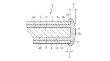
図1は、本発明に係る積層体の第1実施形態を示す。本実施形態では、タッチパネルの保護カバーに用いられる積層体1を例示するが、これに限らず、積層体1は、フラットパネルディスプレイ(FPD)、太陽電池等の各種電気・電子機器用パネルに使用される他、建築構造物や各種車両の窓用パネル、展示物の保護カバー等にも使用され得る(他の実施形態において同じ)。
FIG. 1 shows a first embodiment of a laminate according to the present invention. In the present embodiment, the
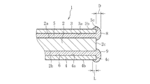
図1に示すように、積層体1は、樹脂板2と、樹脂板2の一方の面(以下「第1の面」という)2aに接着される第1ガラスシート3と、樹脂板2の他方の面(以下「第2の面」という)2bに接着される第2ガラスシート4と、第1ガラスシート3を樹脂板2の第1の面2aに接着する第1接着層5と、第2ガラスシート4を樹脂板2の第2の面2bに接着する第2接着層6とを備え、これらによる5層構造を有する。積層体1を構成する樹脂板2、各ガラスシート3,4及び各接着層5,6には、透明な材質のものが使用される。
As shown in FIG. 1, the
この積層体1の総厚みは、各ガラスシート3,4の厚みの合計(第1ガラスシート3と第2ガラスシート4との厚みの和)の3倍以上とされることが好ましく、5倍以上とされることがより好ましく、10倍以上とされることが最も好ましい。これにより、積層体1に占める樹脂板2の割合を増加させることで、積層体1の軽量化を図ることができる。
The total thickness of the
樹脂板2の厚みは、0.01mm以上20mm以下とされるが、携帯用電子デバイスに搭載されるタッチパネルの保護カバーに用いる場合は、0.1mm以上3mm以下、特に0.1mm以上2mm以下とされることが好ましい。樹脂板2の材質としては、ポリカーボネート、ポリメタアクリル酸メチル樹脂(PMMA)が好ましく、その他に、ポリエチレンテレフタレート、ポリエーテルエーテルケトン(PEEK)、ポリアミド、ポリ塩化ビニル、ポリエチレン、ポリプロピレン、ポリエチレンナフタレート等の各種樹脂材料を利用できる。ここで、樹脂板2には、樹脂フィルムも含まれるものとする。
The thickness of the
各ガラスシート3,4としては、樹脂板2よりも薄板のものが好ましく、その厚みは、500μm以下とされ、好ましくは10μm以上300μm以下とされ、さらに好ましくは50μm以上200μm以下とされる。第1ガラスシート3の厚みと第2ガラスシート4の厚みは同一にされることが好ましいが、これらの厚みを異ならせて積層体1を構成してもよい。
The
ガラスシート3,4の材質としては、ケイ酸塩ガラス、シリカガラスが用いられ、好ましくはホウ珪酸ガラス、ソーダライムガラス、アルミノ珪酸塩ガラス、化学強化ガラスが用いられ、最も好ましくは無アルカリガラスが用いられる。ガラスシート3,4として無アルカリガラスを使用することで、積層体1の透明性を向上させることができる。ここで、無アルカリガラスとは、アルカリ成分(アルカリ金属酸化物)が実質的に含まれていないガラスのことであって、具体的には、アルカリ成分の重量比が3000ppm以下のガラスのことである。本発明におけるアルカリ成分の重量比は、好ましくは1000ppm以下であり、より好ましくは500ppm以下であり、最も好ましくは300ppm以下である。
As the material for the
第1ガラスシート3及び第2ガラスシート4には、同じ種類のガラス材質のものを使用してもよく、また、異なった種類のガラス材質のものを使用してもよい。積層体1をタッチパネルの保護カバーとして使用する場合には、ユーザによるタッチ操作が行われる側のガラスシート(例えば第1ガラスシート3)に、耐候性や耐薬品性により優れる無アルカリガラスによるものを使用し、反対側のガラスシート(例えば第2ガラスシート4)にソーダライムガラス等によるものを使用することもできる。
The
ガラスシート3,4は、その厚みを300μm以下にまで薄肉化しても、大きく撓むことのない適正な剛性を有するように、そのヤング率を可能な限り大きくすることが望ましい。この観点から、ガラスシート3,4のヤング率は、50GPa以上とされ、好ましくは60GPa以上とされ、70GPa以上とされることが最も好ましい。
It is desirable that the Young's modulus of the
ガラスシート3,4は、公知のフロート法、ロールアウト法、スロットダウンドロー法、リドロー法等を使用することができるが、オーバーフローダウンドロー法によって成形されていることが好ましい。オーバーフローダウンドロー法は、断面が略くさび形の成形体の上部に設けられたオーバーフロー溝に溶融ガラスを流し込み、このオーバーフロー溝から両側に溢れ出た溶融ガラスを成形体の両側の側壁部に沿って流下させながら、成形体の下端部で融合一体化し、1枚の板ガラスを連続成形するというものである。
The
オーバーフローダウンドロー法により、厚み300μm以下のガラスシート3,4を大量かつ安価に作製することができる。これにより作製されたガラスシート3,4は、研磨や研削、ケミカルエッチング等によってガラスシート3,4の厚みの調整をする必要がない。また、オーバーフローダウンドロー法は、成形時にガラス板の両面が、成形部材と接触しない成形法であり、得られたガラス板の両面(透光面)は火造り面となり、研磨しなくても高い表面品位を得ることができる。これにより、ガラスシート3,4に対する接着層5,6の密着力を向上させることができ、より正確かつ精密にガラスシート3,4と樹脂板2とを積層させることが可能となる。
By the overflow downdraw method, a large number of
各ガラスシート3,4は、樹脂板2に接着される面(以下「第1の面」という)3a,4aと、この第1の面3a,4aとは反対側に位置する面(以下「第2の面」という)3b,4bと、第1の面3a,4aと第2の面3b,4bとの間に形成される端面3c,4cとを有する。第1ガラスシート3の第1の面3aは、第1接着層5によって樹脂板2の第1の面2aに接着される。また、第2ガラスシート4の第1の面4aは、第2接着層6によって樹脂板2の第2の面2bに接着される。各ガラスシート3,4の第2の面3b,4bは、積層体1の外面を構成するものである。各ガラスシート3,4の端面3c,4cは、樹脂板2の端面2cと面一になるように配置されている。
Each of the
各接着層5,6の厚みは、1μm以上500μm以下とされる。各接着層5,6の材質としては、例えば、エチレン酢酸ビニル共重合樹脂(EVA)、ポリビニルブチラール樹脂(PVB)、及びUV硬化樹脂が好適に使用され得るが、その他に、アクリル系粘着剤、シリコーン系粘着剤、ゴム系粘着剤、紫外線硬化性アクリル系接着剤、紫外線硬化性エポキシ系接着剤、熱硬化性エポキシ系接着剤、熱硬化性メラミン系接着剤、熱硬化性フェノール系接着剤等が使用され得る。
The thickness of each
また、積層体1は、第1接着層5及び第2接着層6が樹脂板2の端面2c及び各ガラスシート3,4の端面3c,4cから食み出ることによって形成される食み出し部7を有する。ガラスシート3,4の端面3c,4cからの食み出し部7の食み出し寸法(突出寸法)Dは、0.01mm以上5mm以下、好ましくは0.1mm以上3mm以下とされる(他の実施形態において同じ)。食み出し部7は、第1接着層5及び第2接着層6と一体に構成されるとともに、各ガラスシート3,4の端面3c,4cの全面、及び樹脂板2の端面2cの全面に接触している。また、食み出し部7は、各ガラスシート3,4の第2の面3b,4bの一部に接触した状態となっている。食み出し部7が各ガラスシート3,4の第2の面3b,4bに接触する範囲Lは、1mm以上3mm以下とされることが好ましい(他の実施形態において同じ)。
Further, the
以下、上記構成の積層体1を製造する方法について説明する。まず、樹脂板2と、樹脂板2と同じ大きさ(面積)のガラスシート3,4とを用意する。次に、ガラスシート3,4の一方(例えば第1ガラスシート3)に接着層(例えば第1接着層5)を積層し、その上に樹脂板2を積層し、この樹脂板2上に接着層(例えば第2接着層6)を積層し、その上に他方のガラスシート(例えば第2ガラスシート4)を積層する。このとき、後の工程において、各接着層5,6が樹脂板2の端面2c及びガラスシート3,4の端面3c,4cから食み出るように、所定サイズの各接着層5,6を積層することが必要である。
Hereinafter, a method for manufacturing the
その後、上記のように樹脂板2、ガラスシート3,4及び接着層5,6を積層した状態で、これらをオートクレーブ装置により熱圧着して接合させる。
Then, in the state where the
この熱圧着により、第1接着層5及び第2接着層6が樹脂板2の端面2c及び各ガラスシート3,4の端面3c,4cから食み出して、樹脂板2の端面2cと各ガラスシート3,4の端面3c,4cに接触し、さらに各ガラスシート3,4の第2の面3b,4bにまで達する。このようにして形成される食み出し部7は、各接着層5,6と一体となったままで硬化し、樹脂板2の端面2c,及び各ガラスシート3,4の端面3c,4cに強固に固着する。以上によって、その端部が食み出し部7によって覆われた積層体1が完成する。
By this thermocompression bonding, the first
なお、紫外線硬化性の接着剤(UV硬化樹脂)を用いて積層体1を製造する場合には、オートクレーブ装置を使用せず、この接着剤を樹脂板2とガラスシート3,4との間に介在させた状態で紫外線を照射する。
When the
以上のように、積層体1は、樹脂板2、各ガラスシート3,4及び各接着層5,6による5層構造を基本とするが、これに限らず、例えば第1ガラスシート3に追加の接着層を介して別のガラスシートをさらに積層することにより、7層以上の多層構造を有していてもよい。
As described above, the
また、積層体1の外面、すなわち、各ガラスシート3,4の第2の面3b,4bに、反射防止膜層や汚染防止膜層を形成してもよい。これらの層は、各ガラスシート3,4が樹脂板2に接着される前に形成され得る。
Further, an antireflection film layer or a pollution prevention film layer may be formed on the outer surface of the
例えば反射防止膜層は、無機材料から構成されていることが好ましく、低屈折率層と高屈折率層の交互膜からなることがより好ましい。低屈折率層としては、酸化ケイ素、酸化アルミニウム及びフッ化マグネシウムからなる群から選ばれた一種であることが好ましく、片面における低屈折膜の総物理膜厚は100nm〜700nmであることが好ましい。また、高屈折率膜としては、窒化ケイ素、窒化アルミニウム、酸化ジルコニウム、酸化ニオブ、酸化タンタル、酸化ハフニウム、酸化チタン、酸化スズ及び酸化亜鉛からなる群から選ばれた一種であることが好ましく、片面における高屈折率膜の総物理膜厚は、50nm〜250nmであることが好ましい。 For example, the antireflection film layer is preferably made of an inorganic material, and more preferably an alternating film of a low refractive index layer and a high refractive index layer. The low refractive index layer is preferably one selected from the group consisting of silicon oxide, aluminum oxide, and magnesium fluoride, and the total physical film thickness of the low refractive film on one side is preferably 100 nm to 700 nm. Further, the high refractive index film is preferably one selected from the group consisting of silicon nitride, aluminum nitride, zirconium oxide, niobium oxide, tantalum oxide, hafnium oxide, titanium oxide, tin oxide and zinc oxide, one sided The total physical film thickness of the high refractive index film in is preferably 50 nm to 250 nm.
ガラスシート3,4に反射防止膜層を形成する方法としては、スパッタ法、真空蒸着法、ディッピング法、スピンコート法、イオンプレーティング法、CVD法等の方法が利用可能であるが、膜厚が均一となり、ガラスシート3,4との接着が強固になり、しかも膜硬度が高くなるという点で、スパッタ法が特に有利である。
As a method for forming the antireflection film layer on the
以上説明した本実施形態に係る積層体1及びその製造方法によれば、各接着層5,6に起因する食み出し部7が各ガラスシート3,4の端面3c,4cに接触していることから、積層体1の側方から他部材が接触したとしても、この他部材は、ガラスシート3,4の端面3c,4cに接触せず、これらを覆う食み出し部7に接触することになる。食み出し部7は、各接着層5,6と一体に構成されるとともに、各ガラスシート3,4の端面3c,4cに固着しているため、他部材が接触したとしても脱落し難くなっており、各端面3c,4cを長期にわたって強固に保護することになる。これにより、各ガラスシート3,4の端面3c,4cの破損や剥離の発生を確実に防止できる。さらに、食み出し部7は、樹脂板2の端面2cの全面と、各ガラスシート3,4の第2の面3b,4bの一部にも接触していることから、積層体1の端部の全てを覆うことになる。これにより、ガラスシート3,4の端面3c,4cに対する他部材の接触を確実に防止し、端面3c,4cにおける損傷や剥離の発生を一層効果的に防止できる。
According to the
また、食み出し部7は、樹脂板2にガラスシート3,4を接着する際に、各接着層5,6が樹脂板2の端面2c及び各ガラスシート3,4の端面3c,4cから食み出ることによって形成されるものであることから、樹脂板2にガラスシート3,4を接着する工程で同時に形成されることになる。したがって、従来のように事後的に樹脂を積層体1の端面に貼り付けるという工程を経る必要はない。したがって、本発明では、製造工数を増加させることなく積層体を製造することが可能である。
In addition, when the
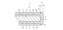
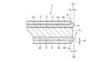
図2は、本発明に係る積層体の第2実施形態を示す。上記の第1実施形態では、食み出し部7が各ガラスシート3,4の第2の面3b,4bの一部にまで接触するように構成されていたが、本実施形態では、食み出し部7は、この第2の面3b,4bに接触しておらず、各ガラスシート3,4の端面3c,4cの全面と、樹脂板2の端面2cの全面とに接触し、これらを覆って保護している。
FIG. 2 shows a second embodiment of the laminated body according to the present invention. In the above-described first embodiment, the protruding
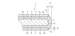
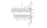
図3は、本発明に係る積層体の第3実施形態を示す。本実施形態では、食み出し部7は、樹脂板2の端面2cの全面に接触しているが、各ガラスシート3,4に関しては、端面3c,4cの全面ではなく、その一部に接触している。食み出し部7がガラスシート3,4の端面3c,4cに接触する範囲Wは、ガラスシート3,4の厚みの半分(1/2)以上であることが望ましい(他の実施形態において同じ)。本実施形態では、食み出し部7は、ガラスシート3,4の厚みの約半分の範囲にわたってその端面3c,4cに接触している。
FIG. 3 shows a third embodiment of the laminated body according to the present invention. In this embodiment, the protruding
このように、食み出し部7は、第1実施形態及び第2実施形態のように各ガラスシート3,4の端面3c,4cの全面に接触するのみならず、各ガラスシート3,4の端面3c,4cの一部に接触することによっても積層体1の端部を保護することができる。すなわち、食み出し部7は、各ガラスシート3,4の端面3c,4cの少なくとも一部に接触することにより、各ガラスシート3,4の損傷や剥離の発生を防止できる。
In this way, the protruding
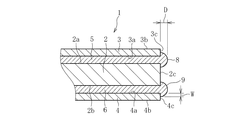
図4は、本発明に係る積層体の第4実施形態を示す。本実施形態に係る積層体1は、樹脂板2の端面2c及び第1ガラスシート3の端面3cから第1接着層5が食み出ることにより形成される第1食み出し部8と、樹脂板2の端面2c及び第2ガラスシート4の端面4cから第2接着層6が食み出ることによって形成される第2食み出し部9とを備える。
FIG. 4 shows a fourth embodiment of the laminated body according to the present invention. The
第1食み出し部8は、第1ガラスシート3の端面3cの一部に接触している。より具体的には、第1食み出し部8は、第1ガラスシート3の厚みの約半分までの範囲にわたって、その端面3cに接触している。また、第1食み出し部8は、樹脂板2の端面2cの一部にも接触している。
The first protruding
第2食み出し部9は、第2ガラスシート4の端面4cの一部に接触している。より具体的には、第2食み出し部9は、第2ガラスシート4の厚みの約半分までの範囲にわたって、その端面4cに接触している。また、第2食み出し部9は、樹脂板2の端面2cの一部にも接触している。
The second
本実施形態と第1実施形態とを比較した場合、本実施形態における第1食み出し部8及び第2食み出し部9は、第1実施形態よりも、各接着層5,6の食み出し量(体積)を少なくすることにより、第1接着層5に対応する位置と第2接着層6に対応する位置との2個所に分かれて形成されることになる。換言すれば、第1実施形態の場合には、各接着層5,6の食み出し量(体積)を本実施形態の場合よりも多くすることにより、第1食み出し部8と第2食み出し部9とが繋がって一体となり、1つの食み出し部7を構成しているとも言える。
When the present embodiment and the first embodiment are compared, the first protruding
図5は、本発明に係る積層体の第5実施形態を示す。本実施形態に係る積層体1では、第1食み出し部8及び第2食み出し部9の構成が第4実施形態と異なる。第4実施形態において、第1食み出し部8は、第1ガラスシート3の端面3cの一部に接触していたが、本実施形態では、第1ガラスシート3の端面3cの全面に接触するとともに、この第1ガラスシート3の第2の面3bの一部にも接触している。同様に、第2食み出し部9は、第2ガラスシート4の端面4cの全面に接触するとともに、この第2ガラスシート4の第2の面4bの一部にも接触している。
FIG. 5: shows 5th Embodiment of the laminated body which concerns on this invention. In the
図6は、本発明に係る積層体の第6実施形態を示す。本実施形態では、樹脂板2の大きさ(面積)が各ガラスシート3,4よりも大きくなっており、樹脂板2の端面2cが、各ガラスシート3,4の端面3c,4cよりも突出している。このため、各ガラスシート3,4の端面3c,4cからの各食み出し部8,9の食み出し寸法(以下「第1食み出し寸法」という)D1と、樹脂板2の端面2cからの各食み出し部8,9の食み出し寸法(以下「第2食み出し寸法」という)D2とが異なっている。具体的には、第2食み出し寸法D2が、第1食み出し寸法D1よりも小さくなっている(D2<D1)。また、各食み出し部8,9は、各ガラスシート3,4の端面3c,4cの一部に接触しているが、樹脂板2の端面2cには接触していない。
FIG. 6 shows a sixth embodiment of the laminate according to the present invention. In the present embodiment, the size (area) of the
図7は、本発明に係る積層体の第7実施形態を示す。本実施形態に係る積層体1は、第1食み出し部8及び第2食み出し部9の構成が第6実施形態と異なる。第6実施形態では、各食み出し部8,9は、各ガラスシート3,4の端面3c,4cの一部に接触していたが、本実施形態では、各食み出し部8,9は、各ガラスシート3,4の端面3c,4cの全面に接触するとともに、各ガラスシート3,4の第2の面3b,4bの一部にも接触している。なお、本実施形態においても第6実施形態と同様に、第2食み出し寸法D2が、第1食み出し寸法D1よりも小さくなっている(D2<D1)。
FIG. 7: shows 7th Embodiment of the laminated body which concerns on this invention. The
なお、本発明に係る積層体は、上記実施形態の構成に限定されるものではない。また、本発明に係る積層体は、上記した作用効果に限定されるものでもない。本発明に係る積層体は、本発明の要旨を逸脱しない範囲で種々の変更が可能である。 The laminate according to the present invention is not limited to the configuration of the above embodiment. Further, the laminated body according to the present invention is not limited to the above-mentioned effects. The laminate according to the present invention can be variously modified without departing from the scope of the present invention.
上記の第1実施形態乃至第7実施形態では、食み出し部7,8,9が樹脂板2の端面2cの全周に亘って食み出している例を示したが、これには限定されず、食み出し部7,8,9は、少なくとも樹脂板2の一部の端面2cから食み出していればよい。
In the above-described first to seventh embodiments, an example is shown in which the protruding
上記の第2実施形態(図2参照)に係る積層体の試験体(実施例)を製造し、その効果を確認した。この試験体では、樹脂板として、151mm×201mm、厚み3.0mmのポリカーボネート板を使用し、各ガラスシートとして、148mm×198mm、厚み200μmのものを使用した。なお、各ガラスシートには、日本電気硝子株式会社製の無アルカリガラス(製品名:OA−10G)を用いた。また、各接着層として、150mm×200mm、厚み400μmのエチレン酢酸ビニル共重合樹脂(EVA)によるものを使用した。 The test body (Example) of the laminated body according to the second embodiment (see FIG. 2) was manufactured, and its effect was confirmed. In this test body, a polycarbonate plate having a size of 151 mm×201 mm and a thickness of 3.0 mm was used as a resin plate, and a glass plate having a size of 148 mm×198 mm and a thickness of 200 μm was used as each glass sheet. For each glass sheet, non-alkali glass (product name: OA-10G) manufactured by Nippon Electric Glass Co., Ltd. was used. As each adhesive layer, a 150 mm×200 mm, 400 μm thick ethylene vinyl acetate copolymer resin (EVA) was used.
接着層を介してポリカーボネート板の両面にガラスシートを重ね合わせ、これに対してオートクレーブ装置による加熱圧着を行った。この場合において、加熱温度120℃、圧力1MPa、加熱圧着時間1時間の条件により加熱圧着を実施した。このような手法により20個の試験体を作製し、各試験体について剥離・損傷の発生の有無に関する試験を実施した。その結果、全ての試験体について剥離・損傷に対する十分な防止効果を確認することができた。 Glass sheets were superposed on both sides of a polycarbonate plate with an adhesive layer interposed therebetween, and then thermocompression bonding was carried out by an autoclave device. In this case, thermocompression bonding was performed under the conditions of a heating temperature of 120° C., a pressure of 1 MPa, and a thermocompression bonding time of 1 hour. Twenty test specimens were produced by such a method, and a test was performed on each specimen for the presence or absence of peeling or damage. As a result, it was possible to confirm a sufficient prevention effect against peeling and damage for all the test bodies.
1 積層体
2 樹脂板
2a 樹脂板の一方の面
2b 樹脂板の他方の面
2c 樹脂板の端面
3 第1ガラスシート
3a 第1ガラスシートの第1の面
3b 第1ガラスシートの第2の面
3c 第1ガラスシートの端面
4 第2ガラスシート
4a 第2ガラスシートの第1の面
4b 第2ガラスシートの第2の面
4c 第2ガラスシートの端面
5 第1接着層
6 第2接着層
7 食み出し部
8 第1食み出し部
9 第2食み出し部DESCRIPTION OF
Claims (11)
前記ガラスシートは、前記樹脂板の一方の面に接着される第1ガラスシートと、前記樹脂板の他方の面に接着される第2ガラスシートとを含み、
前記接着層は、前記樹脂板の前記一方の面に前記第1ガラスシートを接着する第1接着層と、前記樹脂板の前記他方の面に前記第2ガラスシートを接着する第2接着層とを含み、
前記第1ガラスシートは、前記第1接着層を介して前記樹脂板の前記一方の面に接着される第1の面と、前記第1の面とは反対側に位置する第2の面とを有し、
前記第2ガラスシートは、前記第2接着層を介して前記樹脂板の前記他方の面に接着される第1の面と、前記第1の面とは反対側に位置する第2の面とを有し、
前記樹脂板の端面及び前記第1ガラスシートの端面から前記第1接着層が食み出ることにより形成される第1食み出し部と、前記樹脂板の端面及び前記第2ガラスシートの端面から前記第2接着層が食み出ることにより形成される第2食み出し部とを備え、
前記第1食み出し部は、前記第1ガラスシートの前記端面の全面と前記第1ガラスシートの前記第2の面の少なくとも一部とに接触し、
前記第2食み出し部は、前記第2ガラスシートの前記端面の全面と前記第2ガラスシートの前記第2の面の少なくとも一部とに接触することを特徴とする積層体。 In a laminated body in which glass sheets are laminated and integrated on both sides of a resin plate via an adhesive layer,
The glass sheet includes a first glass sheet adhered to one surface of the resin plate and a second glass sheet adhered to the other surface of the resin plate,
The adhesive layer includes a first adhesive layer that adheres the first glass sheet to the one surface of the resin plate, and a second adhesive layer that adheres the second glass sheet to the other surface of the resin plate. Including,
The first glass sheet has a first surface that is adhered to the one surface of the resin plate via the first adhesive layer, and a second surface that is located on the opposite side of the first surface. Have
The second glass sheet has a first surface that is adhered to the other surface of the resin plate via the second adhesive layer, and a second surface that is located on the opposite side of the first surface. Have
From the end surface of the resin plate and the end surface of the first glass sheet, the first protruding portion formed by protruding the first adhesive layer, and from the end surface of the resin plate and the end surface of the second glass sheet A second protruding portion formed by the second adhesive layer protruding,
The first protruding portion contacts the entire surface of the end surface of the first glass sheet and at least a part of the second surface of the first glass sheet ,
The said 2nd protrusion part contacts the whole surface of the said end surface of the said 2nd glass sheet, and at least one part of the said 2nd surface of the said 2nd glass sheet, The laminated body characterized by the above-mentioned .
前記ガラスシートは、前記樹脂板の一方の面に接着される第1ガラスシートと、前記樹脂板の他方の面に接着される第2ガラスシートとを含み、
前記接着層は、前記樹脂板の前記一方の面に前記第1ガラスシートを接着する第1接着層と、前記樹脂板の前記他方の面に前記第2ガラスシートを接着する第2接着層とを含み、
前記樹脂板の端面及び前記第1ガラスシートの端面から前記第1接着層が食み出ることにより形成される第1食み出し部と、前記樹脂板の端面及び前記第2ガラスシートの端面から前記第2接着層が食み出ることにより形成される第2食み出し部とを備え、
前記第1食み出し部及び前記第2食み出し部は、前記樹脂板の前記端面の少なくとも一部に接触し、
前記第1食み出し部は、前記第1ガラスシートの前記端面の少なくとも一部に接触し、前記第2食み出し部は、前記第2ガラスシートの前記端面の少なくとも一部に接触することを特徴とする積層体。 In a laminated body in which glass sheets are laminated and integrated on both sides of a resin plate via an adhesive layer,
The glass sheet includes a first glass sheet adhered to one surface of the resin plate and a second glass sheet adhered to the other surface of the resin plate,
The adhesive layer includes a first adhesive layer that adheres the first glass sheet to the one surface of the resin plate, and a second adhesive layer that adheres the second glass sheet to the other surface of the resin plate. Including,
From the end face of the resin plate and the end face of the first glass sheet, a first protruding portion formed by the first adhesive layer protruding, and from the end face of the resin plate and the end face of the second glass sheet. A second protruding portion formed by protruding the second adhesive layer,
The first protruding portion and the second protruding portion contact at least a part of the end surface of the resin plate ,
The first protruding portion is in contact with at least a portion of the end face of the first glass sheet, said second protruding portion, you contact at least a portion of the end face of the second glass sheet product Sotai you wherein a.
前記ガラスシートは、前記樹脂板の一方の面に接着される第1ガラスシートと、前記樹脂板の他方の面に接着される第2ガラスシートとを含み、
前記接着層は、前記樹脂板の前記一方の面に前記第1ガラスシートを接着する第1接着層と、前記樹脂板の前記他方の面に前記第2ガラスシートを接着する第2接着層とを含み、
前記樹脂板の端面及び前記第1ガラスシートの端面から前記第1接着層が食み出ることにより形成される第1食み出し部と、前記樹脂板の端面及び前記第2ガラスシートの端面から前記第2接着層が食み出ることにより形成される第2食み出し部とを備え、
前記第1食み出し部と前記第2食み出し部とが繋がって一体に構成され、
前記第1食み出し部は、前記第1ガラスシートの前記端面の少なくとも一部に接触し、前記第2食み出し部は、前記第2ガラスシートの前記端面の少なくとも一部に接触することを特徴とする積層体。 In a laminated body in which glass sheets are laminated and integrated on both sides of a resin plate via an adhesive layer,
The glass sheet includes a first glass sheet adhered to one surface of the resin plate and a second glass sheet adhered to the other surface of the resin plate,
The adhesive layer includes a first adhesive layer that adheres the first glass sheet to the one surface of the resin plate, and a second adhesive layer that adheres the second glass sheet to the other surface of the resin plate. Including,
From the end surface of the resin plate and the end surface of the first glass sheet, the first protruding portion formed by protruding the first adhesive layer, and from the end surface of the resin plate and the end surface of the second glass sheet A second protruding portion formed by the second adhesive layer protruding,
The first protruding portion and the second protruding portion are connected to each other and integrally formed ,
The first protruding portion is in contact with at least a portion of the end face of the first glass sheet, said second protruding portion, you contact at least a portion of the end face of the second glass sheet product Sotai you wherein a.
前記ガラスシートは、前記樹脂板の一方の面に接着される第1ガラスシートと、前記樹脂板の他方の面に接着される第2ガラスシートとを含み、
前記接着層は、前記樹脂板の前記一方の面に前記第1ガラスシートを接着する第1接着層と、前記樹脂板の前記他方の面に前記第2ガラスシートを接着する第2接着層とを含み、
前記第1ガラスシートは、前記第1接着層を介して前記樹脂板の前記一方の面に接着される第1の面と、前記第1の面とは反対側に位置する第2の面とを有し、
前記第2ガラスシートは、前記第2接着層を介して前記樹脂板の前記他方の面に接着される第1の面と、前記第1の面とは反対側に位置する第2の面とを有し、
前記樹脂板の端面及び前記第1ガラスシートの端面から前記第1接着層を食み出させることにより第1食み出し部を形成し、
前記樹脂板の端面及び前記第2ガラスシートの端面から前記第2接着層を食み出させることにより第2食み出し部を形成し、
前記第1食み出し部を、前記第1ガラスシートの前記端面の全面と前記第1ガラスシートの前記第2の面の少なくとも一部とに接触させ、
前記第2食み出し部を、前記第2ガラスシートの前記端面の全面と前記第2ガラスシートの前記第2の面の少なくとも一部とに接触させることを特徴とする積層体の製造方法。 In a method for producing a laminated body in which glass sheets are laminated and integrated on both surfaces of a resin plate via an adhesive layer,
The glass sheet includes a first glass sheet adhered to one surface of the resin plate and a second glass sheet adhered to the other surface of the resin plate,
The adhesive layer includes a first adhesive layer that adheres the first glass sheet to the one surface of the resin plate, and a second adhesive layer that adheres the second glass sheet to the other surface of the resin plate. Including,
The first glass sheet has a first surface that is adhered to the one surface of the resin plate via the first adhesive layer, and a second surface that is located on the opposite side of the first surface. Have
The second glass sheet has a first surface that is adhered to the other surface of the resin plate via the second adhesive layer, and a second surface that is located on the opposite side of the first surface. Have
End surface and forming a first protruding portion from the end face Ri by the fact that protrude the first adhesive layer of the first glass sheet of said resin plate,
A second protruding portion is formed by protruding the second adhesive layer from the end surface of the resin plate and the end surface of the second glass sheet,
The first protruding portion is brought into contact with the entire surface of the end surface of the first glass sheet and at least a part of the second surface of the first glass sheet,
The method for producing a laminate, wherein the second protruding portion is brought into contact with the entire surface of the end surface of the second glass sheet and at least a part of the second surface of the second glass sheet .
前記ガラスシートは、前記樹脂板の一方の面に接着される第1ガラスシートと、前記樹脂板の他方の面に接着される第2ガラスシートとを含み、The glass sheet includes a first glass sheet adhered to one surface of the resin plate and a second glass sheet adhered to the other surface of the resin plate,
前記接着層は、前記樹脂板の前記一方の面に前記第1ガラスシートを接着する第1接着層と、前記樹脂板の前記他方の面に前記第2ガラスシートを接着する第2接着層とを含み、The adhesive layer includes a first adhesive layer that adheres the first glass sheet to the one surface of the resin plate, and a second adhesive layer that adheres the second glass sheet to the other surface of the resin plate. Including,
前記樹脂板の端面及び前記第1ガラスシートの端面から前記第1接着層を食み出させることにより第1食み出し部を形成し、A first protruding portion is formed by protruding the first adhesive layer from the end surface of the resin plate and the end surface of the first glass sheet,
前記樹脂板の端面及び前記第2ガラスシートの端面から前記第2接着層を食み出させることにより第2食み出し部を形成し、A second protruding portion is formed by protruding the second adhesive layer from the end surface of the resin plate and the end surface of the second glass sheet,
前記第1食み出し部及び前記第2食み出し部を、前記樹脂板の前記端面の少なくとも一部に接触させ、Contacting the first protruding portion and the second protruding portion with at least a part of the end surface of the resin plate,
前記第1食み出し部を、前記第1ガラスシートの前記端面の少なくとも一部に接触させ、Contacting at least a part of the end face of the first glass sheet with the first protruding portion,
前記第2食み出し部を、前記第2ガラスシートの前記端面の少なくとも一部に接触させることを特徴とする積層体の製造方法。The method for producing a laminate, wherein the second protruding portion is brought into contact with at least a part of the end surface of the second glass sheet.
前記ガラスシートは、前記樹脂板の一方の面に接着される第1ガラスシートと、前記樹脂板の他方の面に接着される第2ガラスシートとを含み、The glass sheet includes a first glass sheet adhered to one surface of the resin plate and a second glass sheet adhered to the other surface of the resin plate,
前記接着層は、前記樹脂板の前記一方の面に前記第1ガラスシートを接着する第1接着層と、前記樹脂板の前記他方の面に前記第2ガラスシートを接着する第2接着層とを含み、The adhesive layer includes a first adhesive layer that adheres the first glass sheet to the one surface of the resin plate, and a second adhesive layer that adheres the second glass sheet to the other surface of the resin plate. Including,
前記樹脂板の端面及び前記第1ガラスシートの端面から前記第1接着層を食み出させることにより第1食み出し部を形成し、A first protruding portion is formed by protruding the first adhesive layer from the end surface of the resin plate and the end surface of the first glass sheet,
前記樹脂板の端面及び前記第2ガラスシートの端面から前記第2接着層を食み出させることにより第2食み出し部を形成し、A second protruding portion is formed by protruding the second adhesive layer from the end surface of the resin plate and the end surface of the second glass sheet,
前記第1食み出し部と前記第2食み出し部とを繋げて一体に構成し、The first protruding portion and the second protruding portion are connected to each other to be integrally configured,
前記第1食み出し部を、前記第1ガラスシートの前記端面の少なくとも一部に接触させ、Contacting at least a part of the end face of the first glass sheet with the first protruding portion,
前記第2食み出し部を、前記第2ガラスシートの前記端面の少なくとも一部に接触させることを特徴とする積層体の製造方法。The method for producing a laminate, wherein the second protruding portion is brought into contact with at least a part of the end surface of the second glass sheet.
Applications Claiming Priority (3)
| Application Number | Priority Date | Filing Date | Title |
|---|---|---|---|
| JP2015046113 | 2015-03-09 | ||
| JP2015046113 | 2015-03-09 | ||
| PCT/JP2016/056451 WO2016143636A1 (en) | 2015-03-09 | 2016-03-02 | Laminate body and manufacturing method thereof |
Publications (2)
| Publication Number | Publication Date |
|---|---|
| JPWO2016143636A1 JPWO2016143636A1 (en) | 2018-01-11 |
| JP6700618B2 true JP6700618B2 (en) | 2020-05-27 |
Family
ID=56879505
Family Applications (1)
| Application Number | Title | Priority Date | Filing Date |
|---|---|---|---|
| JP2017505010A Active JP6700618B2 (en) | 2015-03-09 | 2016-03-02 | Laminated body and manufacturing method thereof |
Country Status (6)
| Country | Link |
|---|---|
| EP (1) | EP3269691B1 (en) |
| JP (1) | JP6700618B2 (en) |
| KR (1) | KR102483097B1 (en) |
| CN (1) | CN107001136B (en) |
| TW (1) | TWI678281B (en) |
| WO (1) | WO2016143636A1 (en) |
Families Citing this family (6)
| Publication number | Priority date | Publication date | Assignee | Title |
|---|---|---|---|---|
| JP6774029B2 (en) * | 2017-04-13 | 2020-10-21 | 日本電気硝子株式会社 | Glass resin laminate |
| DE202018107197U1 (en) * | 2018-12-17 | 2019-03-07 | Ferdi Inci | Bulletproof glass for automatic displays |
| JP2021018524A (en) * | 2019-07-18 | 2021-02-15 | 住友化学株式会社 | Optical laminate and manufacturing method |
| JP2022166863A (en) * | 2019-10-03 | 2022-11-04 | 日本電気硝子株式会社 | Laminate and manufacturing method for laminate |
| WO2023074250A1 (en) * | 2021-10-28 | 2023-05-04 | 日本電気硝子株式会社 | Method for production of glass-resin laminate, and glass-resin laminate |
| KR20230164812A (en) | 2022-05-26 | 2023-12-05 | 오상민 | LED Night Lighting System Using Fine Light Energy Charging Method of Sunlight |
Family Cites Families (13)
| Publication number | Priority date | Publication date | Assignee | Title |
|---|---|---|---|---|
| JPS5617953A (en) * | 1979-07-19 | 1981-02-20 | Tamotsu Nishi | Manufacture of laminated glass |
| JPH08281873A (en) * | 1995-04-12 | 1996-10-29 | Nitto Denzai Kk | Plate-shaped composite material |
| DE10001795A1 (en) * | 2000-01-18 | 2001-07-19 | Bayer Ag | Composite pane consists of an inner pane made of a thermoplastic and outer panes made of glass joined by a thermoplastic polyurethane film |
| JP2002201049A (en) * | 2000-12-27 | 2002-07-16 | Asahi Glass Co Ltd | Laminated glass |
| KR101060352B1 (en) * | 2004-05-29 | 2011-08-29 | 엘지디스플레이 주식회사 | Manufacturing method of flexible display |
| DE102008052066B4 (en) * | 2008-10-17 | 2012-08-30 | Saint-Gobain Sekurit Deutschland Gmbh & Co. Kg | A laminated composite with a translucent or opaque stone layer, process for its preparation and its use |
| JP5510880B2 (en) * | 2009-03-26 | 2014-06-04 | 日本電気硝子株式会社 | Glass film laminate, glass roll of the laminate, and method for producing glass roll |
| DE202010008362U1 (en) * | 2010-08-25 | 2010-12-16 | Schott Ag | Transparent composite material for safety glazing |
| JP5904457B2 (en) * | 2011-05-13 | 2016-04-13 | 日本電気硝子株式会社 | Laminated body |
| CN104722925B (en) * | 2011-05-13 | 2017-09-05 | 日本电气硝子株式会社 | The shearing device and cutting-off method of layered product, the processing method of the cutting-off method of layered product and layered product and fragility plate object |
| DE102012009788A1 (en) * | 2012-05-18 | 2013-11-21 | Schott Ag | Composite material for motor vehicles and aircraft components, has non-inorganic glass as core material and layer (s) arranged on core material and containing inorganic glass |
| DE102012215742A1 (en) * | 2012-09-05 | 2014-03-06 | Bundesdruckerei Gmbh | Safety and / or value product |
| JP2017523108A (en) * | 2014-06-12 | 2017-08-17 | コーニング インコーポレイテッド | Laminating thin glass structures |
-
2016
- 2016-03-02 CN CN201680004214.3A patent/CN107001136B/en active Active
- 2016-03-02 WO PCT/JP2016/056451 patent/WO2016143636A1/en not_active Ceased
- 2016-03-02 KR KR1020177012583A patent/KR102483097B1/en active Active
- 2016-03-02 JP JP2017505010A patent/JP6700618B2/en active Active
- 2016-03-02 EP EP16761606.9A patent/EP3269691B1/en active Active
- 2016-03-08 TW TW105107042A patent/TWI678281B/en active
Also Published As
| Publication number | Publication date |
|---|---|
| TWI678281B (en) | 2019-12-01 |
| TW201704018A (en) | 2017-02-01 |
| JPWO2016143636A1 (en) | 2018-01-11 |
| CN107001136A (en) | 2017-08-01 |
| EP3269691B1 (en) | 2021-06-09 |
| EP3269691A1 (en) | 2018-01-17 |
| WO2016143636A1 (en) | 2016-09-15 |
| EP3269691A4 (en) | 2018-10-17 |
| KR102483097B1 (en) | 2022-12-30 |
| CN107001136B (en) | 2020-12-01 |
| KR20170128768A (en) | 2017-11-23 |
Similar Documents
| Publication | Publication Date | Title |
|---|---|---|
| JP6700618B2 (en) | Laminated body and manufacturing method thereof | |
| US12064939B2 (en) | Flexible display cover, flexible display module, and flexible display apparatus | |
| US11579339B2 (en) | Replaceable cover lens for flexible display | |
| KR101484452B1 (en) | Touch screen protect galss and Method for manufacturing the same | |
| CN1307516C (en) | Touch panel having high durability | |
| KR102071368B1 (en) | Glass film laminate for touch panel, touch panel, and method of manufacturing glass film laminate for touch panel | |
| JP2009301767A (en) | Touch panel, touch panel device and touch panel manufacturing method | |
| US20210174710A1 (en) | Cover, manufacturing method of cover, and display device | |
| CN110780776A (en) | Flexible touch cover plate, preparation method thereof and flexible touch display screen | |
| CN104608445A (en) | A multi-layer elastic composite film having functions of bending shape maintenance and impact resistance and a preparing method thereof | |
| CN109728189B (en) | Display panel and display device | |
| CN104765185B (en) | Liquid crystal display device and preparation method thereof | |
| TWI734906B (en) | Glass resin laminate | |
| WO2016121591A1 (en) | Architectural glass plate provided with display device and architectural glass structure | |
| CN110603496A (en) | Devices comprising crystals or screens | |
| CN204586030U (en) | Multi-layer tempered protective film | |
| US11915623B2 (en) | Flexible display panel, manufacturing method thereof, and flexible display device | |
| CN204506009U (en) | A kind of complex optics being applied to hand-held terminal device | |
| JP2003157149A (en) | Touch panel having high durability | |
| KR101699305B1 (en) | Tempered Glass for Mobile Devices | |
| KR20090086380A (en) | Silicone Pad for Touch Panel | |
| JP2017042989A (en) | Optical laminate | |
| CN219834467U (en) | A heat dissipation component, an electronic equipment component and an electronic equipment | |
| CN216378033U (en) | High-buffering toughened film | |
| CN223355145U (en) | Water vapor barrier film |
Legal Events
| Date | Code | Title | Description |
|---|---|---|---|
| A521 | Request for written amendment filed |
Free format text: JAPANESE INTERMEDIATE CODE: A523 Effective date: 20171110 |
|
| AA64 | Notification of invalidation of claim of internal priority (with term) |
Free format text: JAPANESE INTERMEDIATE CODE: A241764 Effective date: 20171110 |
|
| RD03 | Notification of appointment of power of attorney |
Free format text: JAPANESE INTERMEDIATE CODE: A7423 Effective date: 20171110 |
|
| RD03 | Notification of appointment of power of attorney |
Free format text: JAPANESE INTERMEDIATE CODE: A7423 Effective date: 20171115 |
|
| A621 | Written request for application examination |
Free format text: JAPANESE INTERMEDIATE CODE: A621 Effective date: 20181016 |
|
| A131 | Notification of reasons for refusal |
Free format text: JAPANESE INTERMEDIATE CODE: A131 Effective date: 20191113 |
|
| A521 | Request for written amendment filed |
Free format text: JAPANESE INTERMEDIATE CODE: A523 Effective date: 20200107 |
|
| TRDD | Decision of grant or rejection written | ||
| A01 | Written decision to grant a patent or to grant a registration (utility model) |
Free format text: JAPANESE INTERMEDIATE CODE: A01 Effective date: 20200401 |
|
| A61 | First payment of annual fees (during grant procedure) |
Free format text: JAPANESE INTERMEDIATE CODE: A61 Effective date: 20200414 |
|
| R150 | Certificate of patent or registration of utility model |
Ref document number: 6700618 Country of ref document: JP Free format text: JAPANESE INTERMEDIATE CODE: R150 |