JP6688678B2 - Spinning reel rotation transmission mechanism - Google Patents
Spinning reel rotation transmission mechanism Download PDFInfo
- Publication number
- JP6688678B2 JP6688678B2 JP2016099944A JP2016099944A JP6688678B2 JP 6688678 B2 JP6688678 B2 JP 6688678B2 JP 2016099944 A JP2016099944 A JP 2016099944A JP 2016099944 A JP2016099944 A JP 2016099944A JP 6688678 B2 JP6688678 B2 JP 6688678B2
- Authority
- JP
- Japan
- Prior art keywords
- bearing
- drive shaft
- gear
- transmission mechanism
- rotation transmission
- Prior art date
- Legal status (The legal status is an assumption and is not a legal conclusion. Google has not performed a legal analysis and makes no representation as to the accuracy of the status listed.)
- Active
Links
- 230000005540 biological transmission Effects 0.000 title claims description 48
- 238000009987 spinning Methods 0.000 title claims description 36
- 125000006850 spacer group Chemical group 0.000 claims description 7
- 230000002093 peripheral effect Effects 0.000 description 25
- 238000005096 rolling process Methods 0.000 description 4
- 238000007796 conventional method Methods 0.000 description 2
- 230000002265 prevention Effects 0.000 description 2
- 238000004804 winding Methods 0.000 description 1
Images


Classifications
-
- A—HUMAN NECESSITIES
- A01—AGRICULTURE; FORESTRY; ANIMAL HUSBANDRY; HUNTING; TRAPPING; FISHING
- A01K—ANIMAL HUSBANDRY; CARE OF BIRDS, FISHES, INSECTS; FISHING; REARING OR BREEDING ANIMALS, NOT OTHERWISE PROVIDED FOR; NEW BREEDS OF ANIMALS
- A01K89/00—Reels
- A01K89/01—Reels with pick-up, i.e. with the guiding member rotating and the spool not rotating during normal retrieval of the line
- A01K89/01121—Frame details
- A01K89/011223—Frame details with bearing features
-
- A—HUMAN NECESSITIES
- A01—AGRICULTURE; FORESTRY; ANIMAL HUSBANDRY; HUNTING; TRAPPING; FISHING
- A01K—ANIMAL HUSBANDRY; CARE OF BIRDS, FISHES, INSECTS; FISHING; REARING OR BREEDING ANIMALS, NOT OTHERWISE PROVIDED FOR; NEW BREEDS OF ANIMALS
- A01K89/00—Reels
- A01K89/015—Reels with a rotary drum, i.e. with a rotating spool
- A01K89/0183—Drive mechanism details
- A01K89/0186—Drive mechanism details with disengageable positive drive components, e.g. a clutch
- A01K89/01902—Gear pair
-
- A—HUMAN NECESSITIES
- A01—AGRICULTURE; FORESTRY; ANIMAL HUSBANDRY; HUNTING; TRAPPING; FISHING
- A01K—ANIMAL HUSBANDRY; CARE OF BIRDS, FISHES, INSECTS; FISHING; REARING OR BREEDING ANIMALS, NOT OTHERWISE PROVIDED FOR; NEW BREEDS OF ANIMALS
- A01K89/00—Reels
- A01K89/01—Reels with pick-up, i.e. with the guiding member rotating and the spool not rotating during normal retrieval of the line
- A01K89/0102—Reels with pick-up, i.e. with the guiding member rotating and the spool not rotating during normal retrieval of the line with a closed face
- A01K89/01025—Reels with pick-up, i.e. with the guiding member rotating and the spool not rotating during normal retrieval of the line with a closed face with line snubber shifted by a remote actuator
- A01K89/01026—Reels with pick-up, i.e. with the guiding member rotating and the spool not rotating during normal retrieval of the line with a closed face with line snubber shifted by a remote actuator with rotor and snubber shiftable axially
- A01K89/01029—Reels with pick-up, i.e. with the guiding member rotating and the spool not rotating during normal retrieval of the line with a closed face with line snubber shifted by a remote actuator with rotor and snubber shiftable axially with guiding members shifted radially
-
- A—HUMAN NECESSITIES
- A01—AGRICULTURE; FORESTRY; ANIMAL HUSBANDRY; HUNTING; TRAPPING; FISHING
- A01K—ANIMAL HUSBANDRY; CARE OF BIRDS, FISHES, INSECTS; FISHING; REARING OR BREEDING ANIMALS, NOT OTHERWISE PROVIDED FOR; NEW BREEDS OF ANIMALS
- A01K89/00—Reels
- A01K89/006—Hand crank features
-
- A—HUMAN NECESSITIES
- A01—AGRICULTURE; FORESTRY; ANIMAL HUSBANDRY; HUNTING; TRAPPING; FISHING
- A01K—ANIMAL HUSBANDRY; CARE OF BIRDS, FISHES, INSECTS; FISHING; REARING OR BREEDING ANIMALS, NOT OTHERWISE PROVIDED FOR; NEW BREEDS OF ANIMALS
- A01K89/00—Reels
- A01K89/01—Reels with pick-up, i.e. with the guiding member rotating and the spool not rotating during normal retrieval of the line
- A01K89/0108—Pick-up details
- A01K89/01081—Guiding members on rotor axially rearward of spool
- A01K89/01082—Guiding members shiftable on rotor
-
- A—HUMAN NECESSITIES
- A01—AGRICULTURE; FORESTRY; ANIMAL HUSBANDRY; HUNTING; TRAPPING; FISHING
- A01K—ANIMAL HUSBANDRY; CARE OF BIRDS, FISHES, INSECTS; FISHING; REARING OR BREEDING ANIMALS, NOT OTHERWISE PROVIDED FOR; NEW BREEDS OF ANIMALS
- A01K89/00—Reels
- A01K89/01—Reels with pick-up, i.e. with the guiding member rotating and the spool not rotating during normal retrieval of the line
- A01K89/01121—Frame details
- A01K89/011221—Frame details with line or water shields
-
- A—HUMAN NECESSITIES
- A01—AGRICULTURE; FORESTRY; ANIMAL HUSBANDRY; HUNTING; TRAPPING; FISHING
- A01K—ANIMAL HUSBANDRY; CARE OF BIRDS, FISHES, INSECTS; FISHING; REARING OR BREEDING ANIMALS, NOT OTHERWISE PROVIDED FOR; NEW BREEDS OF ANIMALS
- A01K89/00—Reels
- A01K89/01—Reels with pick-up, i.e. with the guiding member rotating and the spool not rotating during normal retrieval of the line
- A01K89/01121—Frame details
- A01K89/01123—Frame disassembly features
- A01K89/01125—Rotated joints
- A01K89/01126—Threaded
-
- A—HUMAN NECESSITIES
- A01—AGRICULTURE; FORESTRY; ANIMAL HUSBANDRY; HUNTING; TRAPPING; FISHING
- A01K—ANIMAL HUSBANDRY; CARE OF BIRDS, FISHES, INSECTS; FISHING; REARING OR BREEDING ANIMALS, NOT OTHERWISE PROVIDED FOR; NEW BREEDS OF ANIMALS
- A01K89/00—Reels
- A01K89/01—Reels with pick-up, i.e. with the guiding member rotating and the spool not rotating during normal retrieval of the line
- A01K89/0114—Reciprocating mechanisms
- A01K89/01142—Reciprocating mechanisms for reciprocating the guiding member
- A01K89/01143—Reversely threaded screws
-
- A—HUMAN NECESSITIES
- A01—AGRICULTURE; FORESTRY; ANIMAL HUSBANDRY; HUNTING; TRAPPING; FISHING
- A01K—ANIMAL HUSBANDRY; CARE OF BIRDS, FISHES, INSECTS; FISHING; REARING OR BREEDING ANIMALS, NOT OTHERWISE PROVIDED FOR; NEW BREEDS OF ANIMALS
- A01K89/00—Reels
- A01K89/015—Reels with a rotary drum, i.e. with a rotating spool
- A01K89/0192—Frame details
- A01K89/01928—Frame details with line or water shields
-
- A—HUMAN NECESSITIES
- A01—AGRICULTURE; FORESTRY; ANIMAL HUSBANDRY; HUNTING; TRAPPING; FISHING
- A01K—ANIMAL HUSBANDRY; CARE OF BIRDS, FISHES, INSECTS; FISHING; REARING OR BREEDING ANIMALS, NOT OTHERWISE PROVIDED FOR; NEW BREEDS OF ANIMALS
- A01K89/00—Reels
- A01K89/015—Reels with a rotary drum, i.e. with a rotating spool
- A01K89/01931—Spool or spool shaft details
Description
本発明は、スピニングリールの回転伝達機構、特に筐体及び蓋体を有するリール本体に設けられるスピニングリールの回転伝達機構に関する。 The present invention relates to a rotation transmission mechanism for spinning reels, and more particularly to a rotation transmission mechanism for spinning reels provided in a reel body having a housing and a lid.
スピニングリールのリール本体には、回転伝達機構が設けられている(特許文献1を参照)。回転伝達機構は、駆動軸と、駆動ギアと、ピニオンギアとを、有している。駆動軸は、リール本体に対して回転可能に構成される。詳細には、駆動軸は、筐体に設けられた第1軸受と、蓋体に設けられた第2軸受とによって、支持されている。駆動ギアは、駆動軸と一体回転可能に設けられる。ピニオンギアは、駆動ギアに噛み合う。ピニオンギアは、駆動軸と食い違う方向において、筐体に回転可能に支持されている。この構成では、駆動ギア及びピニオンギアの噛み合いを調整するための調整部材(リング部材及び摺動座金)が、第2軸受及び駆動ギアの間に、配置されている。 A rotation transmission mechanism is provided in the reel body of the spinning reel (see Patent Document 1). The rotation transmission mechanism has a drive shaft, a drive gear, and a pinion gear. The drive shaft is configured to be rotatable with respect to the reel body. Specifically, the drive shaft is supported by a first bearing provided on the housing and a second bearing provided on the lid. The drive gear is provided so as to rotate integrally with the drive shaft. The pinion gear meshes with the drive gear. The pinion gear is rotatably supported by the housing in a direction inconsistent with the drive shaft. In this configuration, the adjusting member (ring member and sliding washer) for adjusting the meshing of the drive gear and the pinion gear is arranged between the second bearing and the drive gear.
このタイプの回転伝達機構では、組み立て中に、調整部材が、第2軸受及び駆動ギアの間に配置される。これによって、駆動ギアと一体回転可能な駆動軸が、軸方向に位置決めされる。そして、組み立て後に、ハンドルを回転させることによって、駆動ギア及びピニオンギアの噛み合いの良否、例えばロータの回転のがたつきの程度やロータの回転の軽重等が、判断される。ここで、駆動ギア及びピニオンギアの噛み合いが適切ではない場合、蓋体を筐体から取り外し、調整部材が再調整される。この場合、例えば、調整部材の厚み及び/又は枚数が、変更される。 In this type of rotation transmission mechanism, the adjusting member is arranged between the second bearing and the drive gear during assembly. As a result, the drive shaft that can rotate integrally with the drive gear is positioned in the axial direction. Then, after assembly, the handle is rotated to determine whether or not the meshing of the drive gear and the pinion gear is good, for example, the degree of rattling of the rotation of the rotor, the lightness of rotation of the rotor, and the like. Here, when the engagement between the drive gear and the pinion gear is not appropriate, the lid is removed from the housing, and the adjustment member is readjusted. In this case, for example, the thickness and / or the number of adjusting members are changed.
従来の回転伝達機構では、駆動ギア及びピニオンギアの噛み合いを調整するための調整部材が、蓋体に設けられた第2軸受と、駆動ギアとの間に配置されている。このため、駆動ギア及びピニオンギアの噛み合いを再調整する場合、蓋体を筐体から取り外し、調整部材の調整後に蓋体を筐体に再び取り付ける必要がある。 In the conventional rotation transmission mechanism, an adjusting member for adjusting the meshing of the drive gear and the pinion gear is arranged between the second bearing provided on the lid and the drive gear. Therefore, when readjusting the meshing of the drive gear and the pinion gear, it is necessary to remove the lid from the housing and reattach the lid to the housing after adjusting the adjusting member.
この場合、駆動ギア及びピニオンギアの噛み合いの精度は、筐体に対する蓋体の取り付け精度の影響を受けるおそれがある。すなわち、調整部材の厚み及び枚数を調整したとしても、筐体に対する蓋体の取り付け精度がばらつくと、この取り付け精度のばらつきによって、駆動ギア及びピニオンギアの噛み合いを再調整しなければならなくなるおそれがある。 In this case, the accuracy with which the drive gear and the pinion gear mesh with each other may be affected by the accuracy with which the lid is attached to the housing. That is, even if the thickness and the number of adjusting members are adjusted, if the accuracy of attachment of the lid to the housing varies, the engagement of the drive gear and the pinion gear may have to be readjusted due to the variation in the accuracy of attachment. is there.
また、駆動ギア及びピニオンギアの噛み合いを再調整する場合、上述したように、蓋体及び筐体を、その都度、分解したり組み立てたりする必要があるので、作業性が低下するおそれもある。 Further, when readjusting the meshing of the drive gear and the pinion gear, as described above, it is necessary to disassemble and assemble the lid and the housing each time, which may reduce the workability.
本発明は、上記の問題に鑑みてなされたものであって、本発明の目的は、駆動ギア及びピニオンギアの噛み合いを容易に調整できるスピニングリールの回転伝達機構を、提供することにある。 The present invention has been made in view of the above problems, and an object of the present invention is to provide a rotation transmission mechanism for a spinning reel that can easily adjust the meshing of a drive gear and a pinion gear.
(1)本発明の一側面に係るスピニングリールの回転伝達機構は、筐体及び蓋体を有するリール本体に、設けられる。本回転伝達機構は、駆動軸と、駆動ギアと、ピニオンギアと、第1軸受と、位置決め構造とを、備えている。駆動軸は、筐体に対して回転可能に構成される。駆動ギアは、駆動軸と一体回転可能に設けられる。ピニオンギアは、駆動軸と食い違う方向において筐体に回転可能に支持され、駆動ギアに噛み合う。第1軸受は、筐体に設けられる。第1軸受は、筐体及び駆動軸の間において、駆動軸を回転可能に支持する。位置決め構造は、駆動軸の端部に装着され、第1軸受に対して駆動軸を位置決めする。 (1) The rotation transmission mechanism for a spinning reel according to one aspect of the present invention is provided in a reel body having a housing and a lid. The rotation transmission mechanism includes a drive shaft, a drive gear, a pinion gear, a first bearing, and a positioning structure. The drive shaft is configured to be rotatable with respect to the housing. The drive gear is provided so as to rotate integrally with the drive shaft. The pinion gear is rotatably supported by the housing in a direction inconsistent with the drive shaft and meshes with the drive gear. The first bearing is Ru provided in the housing. The first bearing rotatably supports the drive shaft between the housing and the drive shaft. The positioning structure is attached to an end portion of the drive shaft and positions the drive shaft with respect to the first bearing.
本回転伝達機構では、ピニオンギアは筐体に回転可能に支持された状態で、位置決め構造が、筐体に設けられた第1軸受に対して、駆動軸を位置決めしている。これにより、蓋体を筐体に装着した状態では、ピニオンギアが筐体に回転可能に支持され、駆動軸が位置決め構造によって第1軸受すなわち筐体に位置決めされる。このように回転伝達機構を構成することによって、蓋体を筐体に装着した状態で、駆動ギア及びピニオンギアの噛み合いを容易に調整できる。 In this rotation transmission mechanism, the pinion gear is rotatably supported by the housing, and the positioning structure positions the drive shaft with respect to the first bearing provided in the housing. Thus, when the lid is mounted on the housing, the pinion gear is rotatably supported by the housing, and the drive shaft is positioned by the positioning structure on the first bearing, that is, the housing. By configuring the rotation transmission mechanism in this way, the meshing of the drive gear and the pinion gear can be easily adjusted with the lid mounted on the housing.
(2)本発明の別の側面に係るスピニングリールの回転伝達機構では、位置決め構造が、装着部と、係合部とを、有することが好ましい。装着部は、駆動軸の端部に装着される。係合部は、装着部に設けられる。係合部は、駆動軸の端部側から第1軸受に係合可能に構成されている。このように位置決め構造を構成することによって、簡単な構成で、駆動軸を第1軸受に位置決めすることができる。 (2) In the rotation transmitting mechanism for a spinning reel according to another aspect of the present invention, it is preferable that the positioning structure has a mounting portion and an engaging portion. The mounting portion is mounted on the end of the drive shaft. The engaging portion is provided on the mounting portion. The engagement portion is configured to be engageable with the first bearing from the end side of the drive shaft. By configuring the positioning structure in this way, the drive shaft can be positioned on the first bearing with a simple configuration.
(3)本発明の別の側面に係るスピニングリールの回転伝達機構では、位置決め構造が、スペーサをさらに有することが好ましい。スペーサは、係合部及び第1軸受の間に配置される。係合部は、スペーサを介して、第1軸受に係合する。この場合、スペーサを係合部及び第1軸受の間に配置することによって、駆動軸を第1軸受に好適に位置決めすることができる。 (3) In the rotation transmission mechanism for a spinning reel according to another aspect of the present invention, it is preferable that the positioning structure further includes a spacer. The spacer is arranged between the engaging portion and the first bearing. The engaging portion engages with the first bearing via the spacer. In this case, the drive shaft can be appropriately positioned on the first bearing by disposing the spacer between the engagement portion and the first bearing.
(4)本発明の別の側面に係るスピニングリールの回転伝達機構では、ピニオンギアが、駆動軸の軸方向において、駆動ギア及び第1軸受の間に配置されることが好ましい。このように回転伝達機構を配置することによって、駆動軸を位置決め構造によって第1軸受に位置決めした場合に、駆動ギアをピニオンギアに好適に噛み合わせることができる。 (4) In the rotation transmission mechanism for a spinning reel according to another aspect of the present invention, it is preferable that the pinion gear is arranged between the drive gear and the first bearing in the axial direction of the drive shaft . By arranging the rotation transmitting mechanism in this way, the drive gear can be favorably meshed with the pinion gear when the drive shaft is positioned on the first bearing by the positioning structure.
(5)本発明の別の側面に係るスピニングリールの回転伝達機構は、第2軸受をさらに備えることが好ましい。第2軸受は、蓋体及び駆動軸の間において、駆動軸を回転可能に支持する。これにより、駆動軸を、第1軸受及び第2軸受を介して、筐体及び蓋体において各別に回転可能に支持することができる。 (5) The rotation transmission mechanism of the spinning reel according to another aspect of the present invention preferably further includes a second bearing. The second bearing rotatably supports the drive shaft between the lid and the drive shaft. Thus, the drive shaft can be rotatably supported separately in the housing and the lid via the first bearing and the second bearing.
(6)本発明の別の側面に係るスピニングリールの回転伝達機構では、駆動ギアが、駆動軸の軸方向において、第1軸受及び第2軸受の間に配置されることが好ましい。第2軸受及び駆動ギアの間には、隙間が設けられている。この場合、上記の位置決め構造によって駆動軸が第1軸受に位置決めされるので、従来技術のように第2軸受及び駆動ギアの間に調整部材を配置する必要がない。これにより、蓋体を筐体に装着した状態で、駆動ギア及びピニオンギアの噛み合いを容易に調整できる。 (6) In the rotation transmission mechanism for a spinning reel according to another aspect of the present invention, it is preferable that the drive gear is arranged between the first bearing and the second bearing in the axial direction of the drive shaft . A gap is provided between the second bearing and the drive gear. In this case, since the drive shaft is positioned by the first bearing by the above positioning structure, it is not necessary to dispose the adjusting member between the second bearing and the drive gear as in the conventional technique. Thereby, the engagement of the drive gear and the pinion gear can be easily adjusted with the lid body mounted on the housing.
本発明では、スピニングリールの回転伝達機構において、駆動ギア及びピニオンギアの噛み合いを容易に調整できる。 In the present invention, the meshing of the drive gear and the pinion gear can be easily adjusted in the rotation transmission mechanism of the spinning reel.
<スピニングリールの全体構成>
本発明の一実施形態を採用したスピニングリール1は、釣り竿に装着され、前方に釣り糸を繰り出し可能に構成されている。
<Overall structure of spinning reel>
The
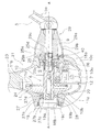
図1及び図2に示すように、本スピニングリール1は、リール本体2と、ロータ3と、スプール4と、ハンドル組立体5と、回転伝達機構6とを、備えている。
As shown in FIGS. 1 and 2, the
ここで、図1に示すO−O軸線は、ロータ3及びスプール4の回転軸心である。また、O−O軸線は、スプール4が装着されたスプール軸15の軸心である。図2に示すA−A軸線は、回転伝達機構6の回転軸芯、例えばハンドル軸9及び駆動軸10の回転軸芯である。
Here, the OO axis shown in FIG. 1 is the rotation axis of the
以下では、軸心Oに沿う方向を“第1軸方向”、軸心Oから離れる方向を“第1径方向”、及び軸心Oまわりの方向を“第1周方向”と、記すことがある。また、軸心Aに沿う方向を“第2軸方向”、軸心Aから離れる方向を“第2径方向”、及び軸心Aまわりの方向を“第2周方向”と、記すことがある。 Hereinafter, a direction along the axis O may be referred to as a “first axial direction”, a direction away from the axis O may be referred to as a “first radial direction”, and a direction around the axis O may be referred to as a “first circumferential direction”. is there. Further, a direction along the axis A may be referred to as a “second axial direction”, a direction away from the axis A may be referred to as a “second radial direction”, and a direction around the axis A may be referred to as a “second circumferential direction”. .
なお、第2軸方向は、第1軸方向と食い違う方向である。A−A軸線はO−O軸線を含む平面に対して平行であり、A−A軸線をこの平面に投影した直線は、O−O軸線と直交している。 The second axis direction is a direction inconsistent with the first axis direction. The A-A axis is parallel to the plane containing the O-O axis, and the straight line obtained by projecting the A-A axis on this plane is orthogonal to the O-O axis.
<リール本体の構成>
リール本体2は、釣り竿に装着可能に構成されている。図1及び図2に示すように、リール本体2は、リールボディ21と、蓋体22と、竿取付脚23とを、有している。
<Structure of reel body>
The
(リールボディ)
図1及び図2に示すように、リールボディ21は、内部空間Sと、開口24(図2を参照)とを、有している。リールボディ21の内部空間Sには、回転伝達機構6が設けられている。また、内部空間Sには、釣り糸をスプール4に均一に巻き取るためのオシレーティング機構7が、設けられている。開口24は、リールボディ21に設けられている。詳細には、開口24は、リールボディ21の側部に設けられている。回転伝達機構6及びオシレーティング機構7は、開口24を介して、リールボディ21の内部空間Sに配置される。
(Reel body)
As shown in FIGS. 1 and 2, the
図2に示すように、リールボディ21の側部(図2の右側部)には、第1ボス部25が形成されている。第1ボス部25は、ハンドル組立体5が装着される側に設けられるボス部である。第1ボス部25は、実質的に筒状に形成され、第2軸方向に延びている。
As shown in FIG. 2, a
第1ボス部25には、第1軸受26が収納されている。第1軸受26は、第1ボス部25に設けられ、後述する駆動軸10の一端部を支持する。第1軸受26については、後述する回転伝達機構6において説明する。
A
第1ボス部25は、雌ねじ部25aと、第1シール孔25bと、第1内壁部25cと、第1軸受収納孔25dとを、有している。
The
雌ねじ部25aは、防水キャップ19を螺合可能に形成されている。雌ねじ部25aの内径(例えば、山径)は、第1軸受26(後述する第1外輪26a)の外径より大きい。すなわち、雌ねじ部25aの内径は、第1軸受収納孔25dの内径より大きい。
The
第1シール孔25bは、第2軸方向において、雌ねじ部25aの外方(外部空間側)に形成されている。第1シール孔25bの内径は、雌ねじ部25aの谷径より大きい。第1シール孔25b及び筒状部材29の軸部29a(後述する)の第2径方向間には、第1シール部材18aが配置される。
The
第1内壁部25cは、第1ボス部25の内周側に設けられている。第1内壁部25cは、実質的に円環状に形成されている。第1内壁部25cには、第1軸受26(後述する第1外輪26a)が当接する。詳細には、第1内壁部25cには、第1軸受26の第1外輪26aが、ハンドル組立体5側から当接する。
The first
第1軸受収納孔25dには、第1軸受26が収納される。第1軸受収納孔25dは、第2軸方向において、雌ねじ部25aの内方(内部空間側)に形成されている。第1軸受収納孔25dの内径は、駆動軸10の外径より大きい。また、第1軸受収納孔25dの内径は、雌ねじ部25aの内径より小さい。
The
(蓋体)
図2に示すように、蓋体22は、リールボディ21に装着される。詳細には、蓋体22は、リールボディ21の開口24を閉塞するように、リールボディ21に装着される。
(Lid)
As shown in FIG. 2, the
蓋体22には、第2ボス部27が形成されている。第2ボス部27は、ハンドル組立体5が装着される側とは反対側に設けられるボス部である。第2ボス部27は、第2軸方向において第1ボス部25に対向可能なように、蓋体22に形成される。第2ボス部27は、実質的に筒状に形成され、第2軸方向に延びている。
A
第2ボス部27には、第2軸受28が収納される。第2軸受28は、第2ボス部27に設けられ、駆動軸10の他端部を支持する。第2軸受28については、後述する回転伝達機構6において説明する。
The
第2ボス部27は、雌ねじ部27aと、第2シール孔27bと、第2内壁部27cと、第2軸受収納孔27dとを、有している。
The
雌ねじ部27aは、防水キャップ19を螺合可能に形成されている。雌ねじ部27aの内径(例えば、山径)は、第2軸受28(後述する第2外輪28a)の外径より大きい。すなわち、雌ねじ部27aの内径は、第2軸受収納孔27dの内径より大きい。
The
第2シール孔27bは、第2軸方向において、雌ねじ部27aの外方に形成されている。第2シール孔27bの内径は、雌ねじ部27aの谷径より大きい。第2シール孔27b及び防水キャップ19の筒状部19b(後述する)との第2径方向間には、第2シール部材18bが配置される。
The
第2内壁部27cは、第2ボス部27の内周側に設けられている。第2内壁部27cは、実質的に円環状に形成されている。第2内壁部27cには、第2軸受28が当接する。詳細には、第2内壁部27cには、第2軸受28の第2外輪28aが、駆動ギア11側から当接する。
The second
第2軸受収納孔27dには、第2軸受28が収納される。第2軸受収納孔27dは、第2軸方向において、雌ねじ部27aの内方(内部空間側)に形成されている。第2軸受収納孔27dの内径は、駆動軸10の外径より大きい。また、第2軸受収納孔27dの内径は、雌ねじ部27aの内径より小さい。
The
図2及び図3に示すように、第2ボス部27は、防水キャップ19により閉塞される。防水キャップ19は、皿状のカバー部19aと、カバー部19aから突出する筒状部19bと、を有している。筒状部19bの先端側の外周面には、雌ねじ部25a,27aのいずれかに螺合可能な雄ねじ部19cが、形成されている。
As shown in FIGS. 2 and 3, the
ここでは、ハンドル組立体5が第1ボス部25側に装着される場合の例を示すが、ハンドル組立体5は、第2ボス部27側にも装着可能に構成されている。この場合、防水キャップ19は、第1ボス部25の雌ねじ部25aに螺合される。
Here, an example in which the
(竿取付脚)
図1及び図2に示すように、竿取付脚23は、釣り竿に装着される。竿取付脚23は、リールボディ21に一体に形成され、リールボディ21から斜め上方に向けて延びている。ここでは、竿取付脚23は、T字状に形成されている。
(Pole mounting leg)
As shown in FIGS. 1 and 2, the
<オシレーティング機構の構成>
図1に示すように、オシレーティング機構7は、スプール4を第1軸方向(例えば前後方向)に移動させるための機構である。詳細には、オシレーティング機構7は、スプール軸15を第1軸方向(例えば前後方向)に移動させることによって、スプール軸15に連結されたスプール4を同方向に移動させるための機構である。オシレーティング機構7は、ピニオンギア12の回転に連動して動作し、ロータ3の回転に同期してスプール4を前後移動させる。ここで、スプール軸15は、スプール4の中心部に配置され、ドラグ機構60を介してスプール4に連結されている。
<Structure of oscillating mechanism>
As shown in FIG. 1, the
<ロータの構成>
図1に示すように、ロータ3は、リール本体2の前部において、回転可能に構成されている。ロータ3は、後述する駆動軸10の回転に連動して回転する。
<Rotor configuration>
As shown in FIG. 1, the
ロータ3は、円筒部30と、円筒部30の側方に互いに対向して設けられた第1及び第2ロータアーム31,32とを、有している。円筒部30と第1及び第2ロータアーム31,32とは、一体成形されている。第1及び第2ロータアーム31,32の先端部には、釣り糸をスプール4に案内するためのベールアーム34が、開閉自在に装着されている。
The
円筒部30の前部には、前壁33が形成されている。前壁33の中央部には、ボス部33aが形成されている。ボス部33aの中心部には、貫通孔が形成されている。貫通孔には、ピニオンギア12の前部12a及びスプール軸15が、挿通されている。貫通孔の前部において、ピニオンギア12は、ナット13により、前壁33に回転不能に係止される
ロータ3の円筒部30の内部には、ロータ3の逆転を禁止・解除するための逆転防止機構50が配置されている。逆転防止機構50は、内輪が遊転するローラ型のワンウェイクラッチ51と、ワンウェイクラッチ51を作動状態(逆転禁止状態)又は非作動状態(逆転許可状態)に切り換える切換機構52とを、有している。
A
<スプールの構成>
スプール4は、リール本体2に対して第1軸方向に移動可能に構成されている。スプール4には、ロータ3の回転により外周に釣り糸が巻き付けられる。
<Structure of spool>
The spool 4 is configured to be movable in the first axis direction with respect to the
図1に示すように、スプール4は、ロータ3の第1ロータアーム31及び第2ロータアーム32の間に、配置されている。スプール4は、ドラグ機構60を介して、スプール軸15の先端部に装着されている。
As shown in FIG. 1, the spool 4 is arranged between the
スプール4は、外周に釣り糸が巻かれる糸巻き胴部4aと、糸巻き胴部4aの後部に一体で形成されたスカート部4bと、糸巻き胴部4aの前端に固定されたフランジ部4cとを、有している。糸巻き胴部4aは、実質的に円筒状に形成されている。糸巻き胴部4aの外周面は、スプール軸15と平行な周面で構成されている。糸巻き胴部4aは、2つの軸受56,57を介して、スプール軸15に回転可能に装着されている。
The spool 4 has a
<ハンドル組立体の構成>
ハンドル組立体5は、後述する駆動軸10と一体回転可能に構成されている。ハンドル組立体5は、駆動軸10の一端側及び他端側のいずれか一方に、一体回転可能且つ着脱自在に装着される。
<Structure of handle assembly>
The
図1及び図2に示すように、ハンドル組立体5は、ハンドルアーム5aと、ハンドル把手5bと、ハンドル軸9(図1参照)と、筒状部材29とを、有している。
As shown in FIGS. 1 and 2, the
ハンドルアーム5aは、ハンドル軸9に揺動可能に連結されている。ハンドル把手5bは、ハンドルアーム5aの先端に装着されている(図1を参照)。
The
ハンドル軸9は、駆動軸10と一体回転可能に構成されている。ハンドル軸9は、後述する駆動軸10の第1雌ねじ部10a又は第2雌ねじ部10bに、螺合する。
The
図3に示すように、ハンドル軸9は、第1雌ねじ部10aに螺合する右ねじの第1雄ねじ部9aと、第2雌ねじ部10bに螺合する左ねじの第2雄ねじ部9bと、筒状部材29の第3雌ねじ部29c(後述する)に螺合する第3雄ねじ部9cとを、有する。
As shown in FIG. 3, the
第1雄ねじ部9aは、ハンドル軸9を駆動軸10の一端側から一体回転可能に装着するためのものである。第1雄ねじ部9aは、第2軸方向において、ハンドル軸9の先端部に形成されている。
The first
第2雄ねじ部9bは、ハンドル軸9を駆動軸10の他端側から一体回転可能に装着するためのものである。第2雄ねじ部9bは、第2軸方向において、第1雄ねじ部9aよりハンドルアーム5a側でハンドル軸9に形成されている。詳細には、第2雄ねじ部9bは、第2軸方向において、第1雄ねじ部9a及び第3雄ねじ部9cの間において、ハンドル軸9に形成されている。
The second
第3雄ねじ部9cは、ハンドル軸9にハンドル組立体5を一体回転可能に装着するためのものである。第3雄ねじ部9cは、第2軸方向において、第2雄ねじ部9bよりハンドルアーム5a側でハンドル軸9に形成されている。
The third
図2に示すように、筒状部材29は、ハンドル軸9と一体回転可能に構成される。筒状部材29は、ハンドル軸9の外周部に配置される。詳細には、筒状部材29は、第2軸方向において、リールボディ21及びハンドルアーム5aの間に配置される。筒状部材29は、第2径方向において、ハンドル軸9の外周部に配置される。
As shown in FIG. 2, the
筒状部材29は、軸部29aと、カバー部29bとを、有している。軸部29aは、実施的に円筒状に形成されている。軸部29aの内周部には、ハンドル軸9が挿通される。詳細には、軸部29aの内周面には、第3雌ねじ部29cが形成されている。第3雌ねじ部29cには、ハンドル軸9の第3雄ねじ部9cが螺合する。
The
<回転伝達機構の構成>
図2及び図3に示すように、回転伝達機構6は、駆動軸10と、駆動ギア11と、ピニオンギア12と、上述した第1軸受26及び第2軸受28と、位置決め構造40とを、有している。
<Structure of rotation transmission mechanism>
As shown in FIGS. 2 and 3, the
(駆動軸)
駆動軸10は、ハンドル組立体5と一体回転可能に構成される。詳細には、駆動軸10は、ハンドル軸9と一体回転可能に構成される。図2及び図3に示すように、駆動軸10には、ハンドル軸9が螺合される。
(Drive shaft)
The
駆動軸10は、実質的に筒状に形成されている。駆動軸10は、第1雌ねじ部10aと、第2雌ねじ部10bと、第4雌ねじ部10cとを、有する。第1雌ねじ部10aは、駆動軸10の中央部において、駆動軸10の内周面に形成されている。第1雌ねじ部10aは、例えば右ねじである。第1雌ねじ部10aには、ハンドル軸9の第1雄ねじ部9aが螺合する。
The
第2雌ねじ部10bは、駆動軸10の他端部(図3の左端部)において、駆動軸10の内周面に形成されている。第2雌ねじ部10bは、例えば左ねじである。第2雌ねじ部10bには、ハンドル軸9の第2雄ねじ部9bが螺合する。
The second
第4雌ねじ部10cは、駆動軸10の一端部(図3の右端部)において、駆動軸10の内周面に形成されている。第4雌ねじ部10cは、例えば右ねじである。第4雌ねじ部10cには、位置決め構造40の位置決め部材41例えば第4雄ねじ部41cが、螺合する。なお、第4雌ねじ部10cは、例えば左ねじであってもよい。
The fourth
また、駆動軸10は、リールボディ21及び蓋体22に対して回転可能に構成される。詳細には、駆動軸10は、第1軸受26及び第2軸受28を介して、リールボディ21及び蓋体22に対して回転可能に支持されている。
The
さらに、駆動軸10は、位置決め構造40によって、リールボディ21に位置決め可能に構成されている。詳細には、駆動軸10は、位置決め構造40によって、第1軸受26すなわちリールボディ21に位置決めされる。
Further, the
(駆動ギア)
駆動ギア11は、駆動軸10の回転をピニオンギア12に伝達する部材である。駆動ギア11は、駆動軸10と一体回転可能に構成されている。また、駆動ギア11は、ピニオンギア12に噛み合い可能に構成されている。
(Drive gear)
The
図2に示すように、駆動ギア11は、駆動軸10と一体に形成されている。駆動ギア11は、第2軸方向において、第1軸受26及び第2軸受28の間に配置されている。駆動ギア11及び第2軸受28の第2軸方向間には、隙間Dが設けられている(図3を参照)。
As shown in FIG. 2, the
具体的には、駆動ギア11は、ギア本体11aと、ギア歯11bとを、有している。ギア本体11aは、駆動軸10の外周部に一体回転可能に設けられている。ギア本体11aは、実質的に円板状に形成されている。ギア本体11aは、第2軸方向において、第1軸受26及び第2軸受28の間において、第2軸受28に隣接して配置されている。ギア本体11a及び第2軸受28の第2軸方向間には、隙間Dが設けられている(図3を参照)。
Specifically, the
ギア歯11bは、ピニオンギア12に噛み合う歯である。ギア歯11bは、ギア本体11aの外周部に設けられている。ギア歯11bは、第2軸方向におけるギア本体11aの一面に、形成されている。詳細には、ギア歯11bは、ギア本体11aの外周部から第2軸方向に向けて突出し、且つギア本体11aの外周部において第2周方向に並べて配置されている。ギア歯11bは、例えばフェースギアである。
The
(ピニオンギア)
図1及び図2に示すように、ピニオンギア12は、駆動ギア11に噛み合い可能に構成されている。また、ピニオンギア12は、オシレーティング機構7に噛み合い可能に構成されている。ピニオンギア12は、実質的に筒状に形成されている。ピニオンギア12の内周部には、スプール軸15が挿通されている。
(Pinion gear)
As shown in FIGS. 1 and 2, the
ピニオンギア12は、スプール軸15まわりに回転可能なように、リール本体2に装着されている。詳細には、ピニオンギア12は、第1軸方向(駆動軸と食い違う方向の一例)に配置され、リールボディ21に対して回転可能に支持されている。すなわち、ピニオンギア12は、第1軸方向においてリールボディ21に位置決めされ、リールボディ21に対して回転可能に支持されている。また、ピニオンギア12は、第2軸方向において、駆動ギア11及び第1軸受26の間に配置されている(図3を参照)。
The
図1に示すように,ピニオンギア12は、ロータ3の中心部を貫通している。ピニオンギア12は、ナット13によりロータ3に固定されている。ピニオンギア12は、第1軸方向における中間部及び後端部で、リールボディ21に回転可能に支持されている。詳細には、ピニオンギア12は、軸受14a,14bを介して、リールボディ21に回転可能に支持されている。
As shown in FIG. 1, the
ピニオンギア12には、図示しないギア歯が形成されている。ギア歯は、駆動ギア11例えば駆動ギア11のギア歯11bに噛み合う歯である。ギア歯は、ピニオンギア12の外周部に設けられている。詳細には、ギア歯は、第1周方向において、ピニオンギア12の外周面に一体に形成されている。ここでは、ギア歯は、例えばはす歯である。
Gear teeth (not shown) are formed on the
(第1軸受及び第2軸受)
図3に示すように、第1軸受26は、リールボディ21に設けられている。第1軸受26は、リールボディ21及び駆動軸10の間において、駆動軸10を回転可能に支持する。
(First bearing and second bearing)
As shown in FIG. 3, the
詳細には、第1軸受26は、リールボディ21の第1ボス部25に設けられている。第1軸受26は、駆動軸10の一端部(図3の右端部)及び第1ボス部25(第1軸受収納孔25d)の第2径方向間において、駆動軸10を回転可能に支持する。
Specifically, the
第1軸受26は、リールボディ21の第1ボス部25の第1軸受収納孔25dに装着される第1外輪26aと、駆動軸10の一端部に装着される第1内輪26bと、第1外輪26a及び第1内輪26bの間に配置される第1転動体26cとを、有する。すなわち、第1軸受26は、転がり軸受、例えば玉軸受である。第1外輪26aは、第2軸方向において、リールボディ21の第1内壁部25cに当接する。第1内輪26bは、後述する位置決め構造40の座金42に当接する。
The
図3に示すように、第2軸受28は、蓋体22に設けられている。第2軸受28は、蓋体22及び駆動軸10の間において、駆動軸10を回転可能に支持する。
As shown in FIG. 3, the
詳細には、第2軸受28は、蓋体22の第2ボス部27に設けられている。第2軸受28は、駆動軸10の他端部(図3の左端部)及び第2ボス部27(第2軸受収納孔27d)の第2径方向間において、駆動軸10を回転可能に支持する。
Specifically, the
第2軸受28は、蓋体22の第2ボス部27の第2軸受収納孔27dに装着される第2外輪28aと、駆動軸10の他端部に装着される第2内輪28bと、第2外輪28a及び第2内輪28bの間に配置される第2転動体28cとを、有する。すなわち、第2軸受28は、転がり軸受、例えば玉軸受である。第2外輪28aは、第2軸方向において、蓋体22の第2内壁部27cに当接する。第2内輪28b及び駆動ギア11の第2軸方向間には、隙間Dが設けられている。
The
(位置決め構造)
図3及び図4に示すように、位置決め構造40は、駆動軸10の端部例えば駆動軸10の一端部(図3の右端部)に、装着される。位置決め構造40は、第1軸受26に対して駆動軸10を位置決めする。詳細には、位置決め構造40は、第1軸受26に対して駆動軸10を位置決めし、駆動ギア11及びピニオンギア12を噛み合わせる。
(Positioning structure)
As shown in FIGS. 3 and 4, the
位置決め構造40は、位置決め部材41と、座金42(スペーサの一例)とを、有している。位置決め部材41は、装着筒部41a(装着部の一例)と、鍔部41b(係合部の一例)とを、有する。
The
装着筒部41aは、実質的に筒状に形成されている。装着筒部41aは、駆動軸10の一端部に装着される。装着筒部41aは、第4雄ねじ部41cを、有している。第4雄ねじ部41cは、装着筒部41aの外周面に形成されている。第4雄ねじ部41cは、例えば右ねじである。第4雄ねじ部41cは、駆動軸10の第4雌ねじ部10cに螺合する。
The mounting
鍔部41bは、第1軸受26に係合可能に構成されている。詳細には、鍔部41bは、駆動軸10の端部側から第1軸受26に係合可能に構成されている。ここでは、鍔部41bは、ハンドル組立体側から、座金42を介して、第1軸受26に係合する。
The
具体的には、鍔部41bは、装着筒部41aに設けられている。詳細には、鍔部41bは、装着筒部41aの端部外周面から径方向外側に突出するように、装着筒部41aに一体に形成されている。
Specifically, the
鍔部41bは、第2軸方向において、駆動軸10の端面に対向して配置される。鍔部41bは、第2軸方向において、第1軸受26例えば第1内輪26bに対向して配置される。鍔部41b及び第1軸受26の第1内輪26bの第2軸方向間には、座金42が配置される。
The
座金42は、実質的に円環板状に形成されている。座金42は、駆動軸の端部外周部に配置される。座金42は、第2軸方向において、鍔部41b及び第1軸受26の間に配置される。
The
詳細には、第2軸方向において、第1軸受26の第1外輪26aが、リールボディ21の第1内壁部25cに当接した状態で、鍔部41bが座金42を第1軸受26の第1内輪26bに向けて押圧する。
Specifically, in the second axial direction, the
このように、位置決め構造40を構成することによって、駆動ギア11がピニオンギア12に噛み合った状態で、駆動軸10が第1軸受26を介してリールボディ21に位置決めされる。
By configuring the
<駆動ギア及びピニオンギアの噛み合い調整>
上記の構成を有するスピニングリール1では、組み立て時に、駆動ギア11及びピニオンギア12の噛み合いが、調整される。噛み合いの調整は、以下のように行われる。
<Engagement adjustment of drive gear and pinion gear>
In the
具体的には、第2軸受28を除く回転伝達機構6が、リールボディ21の内部空間に配置された状態で、第2軸受28を含む蓋体22が、リールボディ21に装着される。これにより、リールボディ21に設けられた第1軸受26、及び蓋体22に設けられた第2軸受28を介して、駆動軸10がリール本体2に回転可能に支持される。
Specifically, the
この状態において、まず、座金42が駆動軸10の端部外周部に配置され、次に、位置決め部材41が駆動軸10の端部に装着される。詳細には、第1軸受26(第1外輪26a)が、リールボディ21の第1内壁部25cに当接した状態で、座金42が位置決め部材41の装着筒部41aの外周部に配置され、装着筒部41a(第4雄ねじ部41c)が、駆動軸10(第4雌ねじ部10c)にねじ込まれる。すると、位置決め部材41の鍔部41bが座金42に当接した状態で、駆動軸10が鍔部41bに向けて移動し、駆動軸10の端面が鍔部41bに当接する。これにより、駆動軸10が、第2軸方向に位置決めされる。
In this state, first, the
このようにして、駆動軸10が、位置決め構造40(位置決め部材41及び座金42)によって、第1軸受26すなわちリールボディ21に、位置決めされる。その結果、駆動ギア11及びピニオンギア12の噛み合いが、所定の噛み合い状態に設定される。
In this way, the
続いて、駆動ギア11及びピニオンギア12の噛み合いが調整される。例えば、図示しない専用工具を駆動軸10に装着し、専用工具を回転させることによって、駆動ギア11及びピニオンギア12の噛み合いの良否が、判断される。ここで、駆動ギア及びピニオンギアの噛み合いが適切でない場合は、位置決め部材41が、駆動軸10から取り外される。そして、座金42の厚み及び/又は枚数が変更され、再び、上記の駆動ギア11及びピニオンギア12の噛み合いの良否が、判断される。
Then, the meshing of the
このように、上記の構成を有する回転伝達機構6では、リールボディ21に蓋体22を装着した状態で、駆動ギア11及びピニオンギア12の噛み合いを、位置決め構造40(位置決め部材41及び座金42)の着脱だけで容易に調整することができる。また、上記の構成を有する回転伝達機構6では、第2軸受28及び駆動ギア11の第2軸方向間には、隙間Dが設けられている。これにより、駆動ギアに対して摺動抵抗が発生しないので、駆動軸10をスムーズに回転させることができる。
As described above, in the
<まとめ>
上記の構成を有するスピニングリール1では、以下のように表現可能である。
<Summary>
The spinning
(1)スピニングリール1の回転伝達機構6は、リールボディ21及び蓋体22を有するリール本体2に、設けられる。本回転伝達機構6は、駆動軸10と、駆動ギア11と、ピニオンギア12と、第1軸受26と、位置決め構造40とを、備えている。駆動軸10は、リールボディ21に対して回転可能に構成される。駆動ギア11は、駆動軸10と一体回転可能に設けられる。ピニオンギア12は、駆動軸10と食い違う方向においてリールボディ21に回転可能に支持され、駆動ギア11に噛み合う。第1軸受26は、リールボディ21に設けられる。第1軸受26は、リールボディ21及び駆動軸10の間において、駆動軸10を回転可能に支持する。位置決め構造40は、駆動軸10の端部に装着され、第1軸受26に対して駆動軸10を位置決めする。
(1) The
本回転伝達機構6では、ピニオンギア12はリールボディ21に回転可能に支持された状態で、位置決め構造40が、リールボディ21に設けられた第1軸受26に対して、駆動軸10を位置決めしている。これにより、蓋体22をリールボディ21に装着した状態では、ピニオンギア12がリールボディ21に回転可能に支持され、駆動軸10が位置決め構造40によって第1軸受26すなわちリールボディ21に位置決めされる。このように回転伝達機構6を構成することによって、蓋体22をリールボディ21に装着した状態で、駆動ギア11及びピニオンギア12の噛み合いを容易に調整できる。
In the present
(2)スピニングリール1の回転伝達機構6では、位置決め構造40が、装着筒部41aと、鍔部41bとを、有することが好ましい。装着筒部41aは、駆動軸10の端部に装着される。鍔部41bは、装着筒部41aに設けられる。鍔部41bは、駆動軸10の一端部側から第1軸受26に係合可能に構成されている。このように位置決め構造40を構成することによって、簡単な構成で、駆動軸10を第1軸受26に位置決めすることができる。
(2) In the
(3)スピニングリール1の回転伝達機構6では、位置決め構造40が、座金42をさらに有することが好ましい。座金42は、鍔部41b及び第1軸受26の間に配置される。鍔部41bは、座金42を介して、第1軸受26に係合する。この場合、座金42を鍔部41b及び第1軸受26の間に配置することによって、駆動軸10を第1軸受26に好適に位置決めすることができる。
(3) In the
(4)スピニングリール1の回転伝達機構6では、ピニオンギア12が、第2軸方向において、駆動ギア11及び第1軸受26の間に配置されることが好ましい。このように回転伝達機構6を配置することによって、駆動軸10を位置決め構造40によって第1軸受26に位置決めした場合に、駆動ギア11をピニオンギア12に好適に噛み合わせることができる。
(4) In the
(5)スピニングリール1の回転伝達機構6は、第2軸受28をさらに備えることが好ましい。第2軸受28は、蓋体22及び駆動軸10の間において、駆動軸10を回転可能に支持する。これにより、駆動軸10を、第1軸受26及び第2軸受28を介して、リールボディ21及び蓋体22において各別に回転可能に支持することができる。
(5) The
(6)スピニングリール1の回転伝達機構6では、駆動ギア11が、第2軸方向において、第1軸受26及び第2軸受28の間に配置されることが好ましい。第2軸受28及び駆動ギア11の間には、隙間Dが設けられている。この場合、上記の位置決め構造40によって駆動軸10が第1軸受26に位置決めされるので、従来技術のように第2軸受28及び駆動ギア11の間に調整部材を配置する必要がない。これにより、蓋体22をリールボディ21に装着した状態で、駆動ギア11及びピニオンギア12の噛み合いを容易に調整できる。
(6) In the
〔他の実施形態〕
(a)前記実施形態では、フロントドラグ型のスピニングリール1を例に説明したが、リアドラグ型のスピニングリール1やレバーブレーキ型のスピニングリール1やクローズドフェイスリールなどの他の形式のスピニングリール1に本発明を適用してもよい。
[Other Embodiments]
(A) In the above-described embodiment, the front drag
(b)前記実施形態では、駆動ギア11を駆動軸10と一体に構成する場合の例を示したが、駆動ギア11を駆動軸10とは別体で構成し、固定手段例えば固定ボルトによって駆動ギア11を駆動軸10に装着してもよい。
(B) In the above embodiment, an example in which the
(c)前記実施形態では、位置決め構造40が1枚の座金42を有する場合の例を示したが、座金42の数は複数であってもよい。
(C) In the above embodiment, the example in which the
(d)前記実施形態では、座金42が円環板状に形成される場合の例を示したが、座金42をC字板状に形成してもよい。この構成によって、駆動軸10に螺合する位置決め部材41を緩めるだけで、座金42を着脱することができる。すなわち、位置決め部材41を駆動軸10から取り外すことなく、座金42を着脱することができる。
(D) In the above embodiment, the example in which the
(e)前記実施形態では、位置決め構造40が座金42を有する場合の例を示したが、位置決め部材41の鍔部41bを、第1軸受26(第1内輪26b)に直接的に当接させてもよい。この場合、鍔部41bを第1軸受26(第1内輪26b)に直接的に当接させた状態で、駆動ギア11及びピニオンギア12の噛み合いの調整が必要になった場合にのみ座金42が用いられる。
(E) Although the example in which the
1 スピニングリール
2 リール本体
6 回転伝達機構
10 駆動軸
11 駆動ギア
12 ピニオンギア
21 リールボディ
22 蓋体
26 第1軸受
28 第2軸受
40 位置決め構造
41a 装着筒部
41b 鍔部
42 座金
D 隙間
1
Claims (6)
前記筐体に対して回転可能に構成される駆動軸と、
前記駆動軸と一体回転可能に設けられる駆動ギアと、
前記駆動軸と食い違う方向において前記筐体に回転可能に支持され、前記駆動ギアに噛み合うピニオンギアと、
前記筐体に設けられ、前記筐体及び前記駆動軸の間において、前記駆動軸を回転可能に支持する第1軸受と、
前記駆動軸の端部に装着され、前記第1軸受に対して前記駆動軸を位置決めする位置決め構造と、
を備えるスピニングリールの回転伝達機構。 A rotation transmission mechanism for a spinning reel, which is provided in a reel body having a housing and a lid,
A drive shaft configured to be rotatable with respect to the housing,
A drive gear that is integrally rotatable with the drive shaft,
A pinion gear that is rotatably supported by the housing in a direction inconsistent with the drive shaft and meshes with the drive gear;
A first bearing provided on the housing and rotatably supporting the drive shaft between the housing and the drive shaft;
A positioning structure mounted on an end of the drive shaft for positioning the drive shaft with respect to the first bearing;
Spin reel rotation transmission mechanism with.
請求項1に記載のスピニングリールの回転伝達機構。 The positioning structure includes a mounting portion mounted on an end portion of the drive shaft, and an engagement portion provided on the mounting portion and configured to be engageable with the first bearing from the end portion side of the drive shaft. Has,
The rotation transmission mechanism of the spinning reel according to claim 1.
前記係合部は、前記スペーサを介して、前記第1軸受に係合する、
請求項2に記載のスピニングリールの回転伝達機構。 The positioning structure further includes a spacer arranged between the engaging portion and the first bearing,
The engaging portion engages with the first bearing via the spacer,
The rotation transmission mechanism of the spinning reel according to claim 2.
請求項1から3のいずれか1項に記載のスピニングリールの回転伝達機構。 The pinion gear is arranged between the drive gear and the first bearing in the axial direction of the drive shaft .
The rotation transmission mechanism for a spinning reel according to any one of claims 1 to 3.
をさらに備える請求項1から4のいずれか1項に記載のスピニングリールの回転伝達機構。 A second bearing that rotatably supports the drive shaft between the lid and the drive shaft;
The rotation transmission mechanism of the spinning reel according to claim 1, further comprising:
前記第2軸受及び前記駆動ギアの間には、隙間が設けられている、
請求項5に記載のスピニングリールの回転伝達機構。 The drive gear is disposed between the first bearing and the second bearing in the axial direction of the drive shaft ,
A gap is provided between the second bearing and the drive gear,
The rotation transmission mechanism of the spinning reel according to claim 5.
Priority Applications (6)
| Application Number | Priority Date | Filing Date | Title |
|---|---|---|---|
| JP2016099944A JP6688678B2 (en) | 2016-05-18 | 2016-05-18 | Spinning reel rotation transmission mechanism |
| KR1020170026074A KR20170130276A (en) | 2016-05-18 | 2017-02-28 | Rotation transmission mechanism for spinning reel |
| US15/450,987 US10278377B2 (en) | 2016-05-18 | 2017-03-06 | Rotation transmission mechanism for spinning reel |
| TW106107984A TWI698175B (en) | 2016-05-18 | 2017-03-10 | Rotation transmission mechanism for spinning reel |
| EP17163454.6A EP3245868B1 (en) | 2016-05-18 | 2017-03-29 | Spinning reel comprising a rotation transmission mechanism |
| CN201710261438.9A CN107410235B (en) | 2016-05-18 | 2017-04-20 | Rotation transmission mechanism of spinning reel |
Applications Claiming Priority (1)
| Application Number | Priority Date | Filing Date | Title |
|---|---|---|---|
| JP2016099944A JP6688678B2 (en) | 2016-05-18 | 2016-05-18 | Spinning reel rotation transmission mechanism |
Publications (3)
| Publication Number | Publication Date |
|---|---|
| JP2017205065A JP2017205065A (en) | 2017-11-24 |
| JP2017205065A5 JP2017205065A5 (en) | 2019-05-30 |
| JP6688678B2 true JP6688678B2 (en) | 2020-04-28 |
Family
ID=58461085
Family Applications (1)
| Application Number | Title | Priority Date | Filing Date |
|---|---|---|---|
| JP2016099944A Active JP6688678B2 (en) | 2016-05-18 | 2016-05-18 | Spinning reel rotation transmission mechanism |
Country Status (6)
| Country | Link |
|---|---|
| US (1) | US10278377B2 (en) |
| EP (1) | EP3245868B1 (en) |
| JP (1) | JP6688678B2 (en) |
| KR (1) | KR20170130276A (en) |
| CN (1) | CN107410235B (en) |
| TW (1) | TWI698175B (en) |
Families Citing this family (6)
| Publication number | Priority date | Publication date | Assignee | Title |
|---|---|---|---|---|
| JP6856355B2 (en) * | 2016-11-08 | 2021-04-07 | 株式会社シマノ | Waterproof structure of fishing reel |
| JP6979785B2 (en) * | 2017-04-26 | 2021-12-15 | 株式会社シマノ | Spinning reel |
| JP7049795B2 (en) * | 2017-09-29 | 2022-04-07 | 株式会社シマノ | Fishing reel |
| JP7065643B2 (en) * | 2018-03-01 | 2022-05-12 | 株式会社シマノ | Fishing reel |
| US11350617B2 (en) | 2019-06-21 | 2022-06-07 | Trika Inc. | Left handed fishing reel |
| CN111771829A (en) * | 2020-08-24 | 2020-10-16 | 广州辉悦贸易有限公司 | Spinning wheel type fishing reel |
Family Cites Families (24)
| Publication number | Priority date | Publication date | Assignee | Title |
|---|---|---|---|---|
| US4222462A (en) * | 1978-10-11 | 1980-09-16 | Ottestad Jack Benton | Brake to decelerate axially moving actuating rod |
| JPS5831501Y2 (en) * | 1978-12-20 | 1983-07-12 | オリムピツク釣具株式会社 | Handle mounting structure for fishing reel |
| JP2514526Y2 (en) * | 1990-07-26 | 1996-10-23 | 株式会社シマノ | Spinning reel |
| JPH05184269A (en) * | 1992-01-13 | 1993-07-27 | Shimano Inc | Spinning reel |
| JPH0623455U (en) * | 1992-08-28 | 1994-03-29 | 株式会社シマノ | Spinning reel |
| EP0641514B1 (en) * | 1993-09-08 | 1998-01-07 | Daiwa Seiko Inc. | Handle mounting structure in fishing reel |
| JPH10210901A (en) | 1997-01-29 | 1998-08-11 | Shimano Inc | Engagement-adjusting mechanism for face gear of spinning reel |
| JP3583340B2 (en) * | 2000-01-13 | 2004-11-04 | ダイワ精工株式会社 | Spinning reel for fishing |
| JP3961757B2 (en) * | 2000-09-29 | 2007-08-22 | 株式会社シマノ | Parts support structure for fishing reel |
| JP4045167B2 (en) * | 2002-05-01 | 2008-02-13 | 株式会社シマノ | Spinning reel handle assembly |
| US6626385B1 (en) * | 2002-08-01 | 2003-09-30 | Daiwa Seiko, Inc. | Spinning reel for fishing |
| JP4015957B2 (en) * | 2003-01-20 | 2007-11-28 | 株式会社シマノ | Spinning reel handle assembly |
| SG121940A1 (en) * | 2004-10-06 | 2006-05-26 | Shimano Kk | Handle knob and handle assembly for a fishing reel |
| JP4804279B2 (en) * | 2006-08-31 | 2011-11-02 | 株式会社シマノ | Spinning reel |
| JP2009000078A (en) * | 2007-06-25 | 2009-01-08 | Shimano Inc | Spinning transmission mechanism for spinning reel |
| EP2147595A1 (en) * | 2008-07-23 | 2010-01-27 | Wen-Hsiang Lee | Fishing-reel driving device |
| JP2010273629A (en) * | 2009-05-29 | 2010-12-09 | Shimano Components Malaysia Sdn Bhd | Handle assembly of fishing reel |
| JP5300999B2 (en) * | 2012-02-27 | 2013-09-25 | グローブライド株式会社 | Fishing reel |
| JP6027805B2 (en) * | 2012-07-24 | 2016-11-16 | 株式会社シマノ | Spinning reel handle assembly |
| JP2014155470A (en) * | 2013-02-18 | 2014-08-28 | Shimano Inc | Pinion gear of double-bearing reel, and double-bearing reel having the same |
| EP2853159B1 (en) * | 2013-09-27 | 2017-04-05 | Globeride, Inc. | Fishing spinning reel |
| JP6342640B2 (en) * | 2013-10-25 | 2018-06-13 | グローブライド株式会社 | Fishing reel |
| US10010061B2 (en) * | 2015-03-18 | 2018-07-03 | Shimano Inc. | Spinning reel |
| CN204969031U (en) * | 2015-09-25 | 2016-01-20 | 宁波市北仑海伯精密机械制造有限公司 | Shake wire structure of wheel |
-
2016
- 2016-05-18 JP JP2016099944A patent/JP6688678B2/en active Active
-
2017
- 2017-02-28 KR KR1020170026074A patent/KR20170130276A/en not_active Application Discontinuation
- 2017-03-06 US US15/450,987 patent/US10278377B2/en active Active
- 2017-03-10 TW TW106107984A patent/TWI698175B/en active
- 2017-03-29 EP EP17163454.6A patent/EP3245868B1/en active Active
- 2017-04-20 CN CN201710261438.9A patent/CN107410235B/en active Active
Also Published As
| Publication number | Publication date |
|---|---|
| TW201740801A (en) | 2017-12-01 |
| JP2017205065A (en) | 2017-11-24 |
| US10278377B2 (en) | 2019-05-07 |
| EP3245868A1 (en) | 2017-11-22 |
| KR20170130276A (en) | 2017-11-28 |
| CN107410235A (en) | 2017-12-01 |
| TWI698175B (en) | 2020-07-11 |
| EP3245868B1 (en) | 2021-08-04 |
| CN107410235B (en) | 2021-09-17 |
| US20170332614A1 (en) | 2017-11-23 |
Similar Documents
| Publication | Publication Date | Title |
|---|---|---|
| JP6688678B2 (en) | Spinning reel rotation transmission mechanism | |
| JP2017205065A5 (en) | ||
| JP6166558B2 (en) | Double bearing reel | |
| KR101396775B1 (en) | Spinning reel handle assembly | |
| KR101975425B1 (en) | Torque limiting device for fishing reel | |
| TWI389639B (en) | Spinning reel | |
| KR101942879B1 (en) | Handle assembly for dual-bearing reel and dual-bearing reel | |
| JP5878718B2 (en) | Double bearing reel | |
| KR101806336B1 (en) | Master gear assembly | |
| JP2013070651A5 (en) | ||
| JP6140956B2 (en) | Spinning reel | |
| JP2014057544A5 (en) | ||
| JP6219702B2 (en) | Fishing reel drive gear and fishing reel pinion gear | |
| JP2004222525A (en) | Handle assembly of spinning reel | |
| JP2009000078A (en) | Spinning transmission mechanism for spinning reel | |
| JP2015112099A5 (en) | ||
| JP4476128B2 (en) | Spinning reel master gear | |
| JP2001231414A (en) | Handle assembly of spinning reel | |
| JP4272489B2 (en) | Reel body of double-bearing reel | |
| JP4015931B2 (en) | Fishing reel screw operation structure | |
| JP3884314B2 (en) | Spinning reel master gear | |
| JP2003079287A (en) | Structure for attaching handle of spinning reel | |
| JP2012170434A (en) | Double bearing reel | |
| JP6110128B2 (en) | Spinning reel and spinning reel spool | |
| JP2004141040A (en) | Handle assembly of spinning reel |
Legal Events
| Date | Code | Title | Description |
|---|---|---|---|
| A521 | Request for written amendment filed |
Free format text: JAPANESE INTERMEDIATE CODE: A523 Effective date: 20190417 |
|
| A621 | Written request for application examination |
Free format text: JAPANESE INTERMEDIATE CODE: A621 Effective date: 20190417 |
|
| A977 | Report on retrieval |
Free format text: JAPANESE INTERMEDIATE CODE: A971007 Effective date: 20200228 |
|
| TRDD | Decision of grant or rejection written | ||
| A01 | Written decision to grant a patent or to grant a registration (utility model) |
Free format text: JAPANESE INTERMEDIATE CODE: A01 Effective date: 20200310 |
|
| A61 | First payment of annual fees (during grant procedure) |
Free format text: JAPANESE INTERMEDIATE CODE: A61 Effective date: 20200406 |
|
| R150 | Certificate of patent or registration of utility model |
Ref document number: 6688678 Country of ref document: JP Free format text: JAPANESE INTERMEDIATE CODE: R150 |
|
| R250 | Receipt of annual fees |
Free format text: JAPANESE INTERMEDIATE CODE: R250 |
|
| R250 | Receipt of annual fees |
Free format text: JAPANESE INTERMEDIATE CODE: R250 |