JP3961757B2 - Parts support structure for fishing reel - Google Patents
Parts support structure for fishing reel Download PDFInfo
- Publication number
- JP3961757B2 JP3961757B2 JP2000300369A JP2000300369A JP3961757B2 JP 3961757 B2 JP3961757 B2 JP 3961757B2 JP 2000300369 A JP2000300369 A JP 2000300369A JP 2000300369 A JP2000300369 A JP 2000300369A JP 3961757 B2 JP3961757 B2 JP 3961757B2
- Authority
- JP
- Japan
- Prior art keywords
- corrosion
- bearing
- spool
- rolling elements
- support structure
- Prior art date
- Legal status (The legal status is an assumption and is not a legal conclusion. Google has not performed a legal analysis and makes no representation as to the accuracy of the status listed.)
- Expired - Fee Related
Links
Images


Classifications
-
- A—HUMAN NECESSITIES
- A01—AGRICULTURE; FORESTRY; ANIMAL HUSBANDRY; HUNTING; TRAPPING; FISHING
- A01K—ANIMAL HUSBANDRY; CARE OF BIRDS, FISHES, INSECTS; FISHING; REARING OR BREEDING ANIMALS, NOT OTHERWISE PROVIDED FOR; NEW BREEDS OF ANIMALS
- A01K89/00—Reels
- A01K89/015—Reels with a rotary drum, i.e. with a rotating spool
- A01K89/0192—Frame details
- A01K89/0193—Frame details with bearing features
-
- A—HUMAN NECESSITIES
- A01—AGRICULTURE; FORESTRY; ANIMAL HUSBANDRY; HUNTING; TRAPPING; FISHING
- A01K—ANIMAL HUSBANDRY; CARE OF BIRDS, FISHES, INSECTS; FISHING; REARING OR BREEDING ANIMALS, NOT OTHERWISE PROVIDED FOR; NEW BREEDS OF ANIMALS
- A01K89/00—Reels
- A01K89/015—Reels with a rotary drum, i.e. with a rotating spool
-
- A—HUMAN NECESSITIES
- A01—AGRICULTURE; FORESTRY; ANIMAL HUSBANDRY; HUNTING; TRAPPING; FISHING
- A01K—ANIMAL HUSBANDRY; CARE OF BIRDS, FISHES, INSECTS; FISHING; REARING OR BREEDING ANIMALS, NOT OTHERWISE PROVIDED FOR; NEW BREEDS OF ANIMALS
- A01K89/00—Reels
-
- A—HUMAN NECESSITIES
- A01—AGRICULTURE; FORESTRY; ANIMAL HUSBANDRY; HUNTING; TRAPPING; FISHING
- A01K—ANIMAL HUSBANDRY; CARE OF BIRDS, FISHES, INSECTS; FISHING; REARING OR BREEDING ANIMALS, NOT OTHERWISE PROVIDED FOR; NEW BREEDS OF ANIMALS
- A01K89/00—Reels
- A01K89/01—Reels with pick-up, i.e. with the guiding member rotating and the spool not rotating during normal retrieval of the line
- A01K89/01121—Frame details
- A01K89/011223—Frame details with bearing features
-
- A—HUMAN NECESSITIES
- A01—AGRICULTURE; FORESTRY; ANIMAL HUSBANDRY; HUNTING; TRAPPING; FISHING
- A01K—ANIMAL HUSBANDRY; CARE OF BIRDS, FISHES, INSECTS; FISHING; REARING OR BREEDING ANIMALS, NOT OTHERWISE PROVIDED FOR; NEW BREEDS OF ANIMALS
- A01K89/00—Reels
- A01K89/015—Reels with a rotary drum, i.e. with a rotating spool
- A01K89/0192—Frame details
- A01K89/01928—Frame details with line or water shields
Landscapes
- Life Sciences & Earth Sciences (AREA)
- Environmental Sciences (AREA)
- Animal Husbandry (AREA)
- Biodiversity & Conservation Biology (AREA)
- Rolling Contact Bearings (AREA)
Description
【0001】
【発明の属する技術分野】
本発明は、部品支持構造、特に、スピニングリールや両軸受リール等の釣り用リールの相対回転する第1部品と第1部品の内周側に配置された第2部品との間に設けられた釣り用リールの部品支持構造に関する。
【0002】
【従来の技術】
スピニングリールや両軸受リール等の釣り用リールには、リール本体や他の部品に対して相対回転するロータやスプールやハンドル軸等の回転部品が多く用いられている。この種の回転部品は軸受によりリール本体や他の部品に回転自在に装着されている。この回転部品を支持する軸受として釣り用リールの場合、玉軸受が多く使用されている。
【0003】
一般に、釣り用リールは水分が付着して腐食しやすい雰囲気で使用されるため、玉軸受の耐食性を向上させることが望まれる。従来、玉軸受の耐食性を向上させるために、特に海釣りに使用される釣り用リールに用いられる玉軸受の材質としては錆びにくいステンレス鋼が使用されている。このステンレス鋼のなかでも回転性能やコストを考慮して玉軸受の転動体には焼き入れ可能なSUS440Cが多く用いられている。すなわち、SUS440Cは強度が高く耐衝撃性も軸受としての仕様上十分でありかつ加工精度を高く維持できるため回転性能を高く維持できるのである。しかし、SUS440Cは、SUS304,SUS316等のオーステナイト系のものに比べて硬いが耐食性が低いという問題がある。このため、腐食を防止するために軸受自体を防水構造にしたほうがよい。軸受を防水構造にするために、ゴム製のシール部材が内輪と外輪との間に両者に接触するように装着されたゴムシール型の玉軸受が多く使用されている。ゴムシール型の玉軸受では、少なくとも玉軸受の液体浸入側にシール部材が装着されている。
【0004】
【発明が解決しようとする課題】
シールド軸受により軸受の腐食を防止すると、シール部材が内外輪に接触するために、回転の負荷が高くなり回転性能が低下する。回転性能を維持するためには非接触のシール部材を用いればよいが、非接触のものではシール性能が悪く、特に海釣り用の釣り用リールに用いるには耐食性が十分ではない。
【0005】
一方、シール部材を液体浸入側に配置すると、腐食を防止するためには効果がある。しかし、たとえば海釣りを行った後にホースで水をかけて洗うとき、軸受に水が浸入しないため、軸受を洗浄することができない。シール部材を設けなければ洗浄は可能になるが、洗浄用の水がリール内部に浸入して内部部品の腐食や塩かみが生じるおそれがある。
【0006】
本発明の課題は、回転性能の低下を抑えて軸受の耐蝕性を向上させることにある。
【0007】
本発明の別の課題は、内部部品の腐食を招くことなく軸受を洗浄しやすくすることにある。
【0008】
【課題を解決するための手段】
発明1に係る釣り用リールの部品支持構造は、釣り用リールの第1部品と第1部品の内周側に配置された第2部品とを相対回転自在に支持する構造であって、軸受と、シール部材とを備えている。軸受は、外部から液体が浸入可能な位置に配置されたものである。軸受は、外輪と内輪と複数の転動体とを備えている。外輪は、第1部品に装着されたものである。内輪は、第2部品に装着され外輪と隙間をあけて配置されたものである。複数の転動体は、両輪の間に両輪と接触して周方向に間隔を隔てて配置されたものである。内輪、外輪、及び転動体のうち少なくとも転動体は耐食材料製又は耐食性被膜で被覆された金属製ものである。シール部材は、軸受より液体浸入側と逆側に配置され、両部品の隙間をシールする部材である。この場合には、海水等が浸入しても軸受が腐食しにくいとともに、洗浄用の水などが軸受に浸入可能になり、海水で汚れた軸受を簡単に洗浄できる。しかも、軸受の奥側にシール部材が装着されているので、液体がそれ以上奥に浸入しなくなり、内部部品の腐食を防止できる。
【0009】
また、軸受では、2つの部品が相対回転すると、内輪と外輪とが相対回転し、転動体が両者に接触して自転及び公転しながら間隔を隔てて転がる。ここでは、少なくとも転動体が耐食材料製または耐食被膜で被覆された金属製であるので、回転中は常に転がる転動体の耐蝕性が高くなる。このため、軸受全体の耐食性が向上する。また、耐食性が向上するので腐食を防止するためのシール部材を設ける必要がなくなる。このため、回転性能の低下を抑えることができる。
【0010】
発明2に係る釣り用リールの部品支持構造は、釣り用リールの第1部品と第1部品の内周側に配置された第2部品とを相対回転自在に支持する構造であって、軸受と、シール部材とを備えている。軸受は、外部から液体が浸入可能な位置に配置されたものである。軸受は、外輪と内輪と複数の転動体とを備えている。外輪は、第1部品に装着されたものである。内輪は、第2部品に装着され外輪と隙間をあけて配置されたものである。複数の転動体は、両輪の間に両輪と接触して周方向に間隔を隔てて配置されたものである。内輪、外輪、及び転動体のうち少なくとも転動体は耐食材料製又は耐食性被膜で被覆された金属製ものである。シール部材は、転動体より液体浸入側と逆側に配置され、両輪の隙間をシールするものである。この場合には、海水等が浸入しても軸受が腐食しにくいとともに、洗浄用の水などが軸受に浸入可能になり、海水で汚れた軸受を簡単に洗浄できる。しかも、転動体の奥側にシール部材が装着されているので、液体がそれ以上奥に浸入しなくなり、内部部品の腐食を防止できる。
【0011】
また、軸受では、2つの部品が相対回転すると、内輪と外輪とが相対回転し、転動体が両者に接触して自転及び公転しながら間隔を隔てて転がる。ここでは、少なくとも転動体が耐食材料製または耐食被膜で被覆された金属製であるので、回転中は常に転がる転動体の耐蝕性が高くなる。このため、軸受全体の耐食性が向上する。また、耐食性が向上するので腐食を防止するためのシール部材を設ける必要がなくなる。このため、回転性能の低下を抑えることができる。
【0012】
発明3に係る釣り用リールの部品支持構造は、発明1又は2に記載の構造において、軸受は、転動体を周方向に間隔を隔てて転動自在に保持する耐食性材料製又は耐食性被膜で被覆された金属材料製のリテーナをさらに備える。この場合には、転動体に接触しているリテーナが耐食性を有しているので、転動体の転動がリテーナの腐食により妨げられることがない。
【0013】
発明4に係る釣り用リールの部品支持構造は、発明1から3のいずれかに記載の構造において、少なくとも転動体はセラミック製である。この場合には、腐食しないセラミックにより少なくとも転動体の耐食性をさらに高く維持できる。
【0014】
発明5に係る釣り用リールの部品支持構造は、発明1から3のいずれかに記載の構造において、少なくとも転動体は耐食性被膜で被覆されたステンレス合金製である。この場合には、耐食被膜が剥離しても腐食しにくくなる。
【0015】
発明6に係る釣り用リールの部品支持構造は、発明5に記載の構造において、耐食被膜は、ステンレス合金の表面を改質して形成されている。この場合には、耐食被膜がステンレス合金の表面を改質処理して形成されているので、メッキやコーティング処理に比べて耐食被膜が剥離しにくくなる。また、あとからメッキやコーティング処理を施すと母材の真円度(真球度)がそれらの加工精度によりが損なわれるおそれがあるが、改質処理では母材の真円度(真球度)が損なわれにくい。
【0016】
発明7に係る釣り用リールの部品支持構造は、発明6に記載の構造において、少なくとも転動体は低耐食性材料であるSUS440C製である。この場合に母材の耐食性は劣るが、母材の比強度が高くなり軸受の寿命が長くなる。
【0017】
【発明の実施の形態】
〔実施形態1〕
図1及び図2において、本発明の一実施形態が採用された両軸受リールは、ベイトキャスト用のロープロフィール型のリールである。このリールは、リール本体1と、リール本体1の側方に配置されたスプール回転用ハンドル2と、リール本体1の内部に回転自在かつ着脱自在に装着された糸巻用のスプール12とを備えている。ハンドル2のリール本体1側には、ドラグ調整用のスタードラグ3が設けられている。
【0018】
ハンドル2は、板状のハンドルアーム2aと、ハンドルアーム2aの両端に回転自在に装着された把手部2bとを有するダブルハンドル形のものである。ハンドルアーム2aは、図3に示すように、ナット2dによりハンドル軸30の先端に回転不能に固定された座板2cに2本のビス2eにより固定されている。このナット2dは、ハンドルアーム2aの内部に収納されて回り止めされている。このため、ハンドルアーム2aの外側面つなぎ目がない滑らかな面で構成することができ、釣り糸が絡みにくい構造となっている。
【0019】
図3に示すように、リール本体1は、フレーム5と、フレーム5の両側方に装着された第1側カバー6a及び第2側カバー6bとを有している。また、リール本体1は、図1及び図2に示すように、前方を覆う前カバー7と、上部を覆うサムレスト8とを有している。
【0020】
フレーム5は、図3に示すように所定の間隔をあけて互いに対向するように配置された1対の側板5a,5bと、これらの側板5a,5bを連結する複数の連結部5c(図5参照)とを有している。下側の2つの連結部5cには、図4及び図5に示すように、リールを釣り竿Rに装着するための前後に長い、たとえばステンレス等の金属製の装着脚部4がネジ止めされている。
【0021】
第1側カバー6aは、スプール12の着脱を可能にするためにフレーム5に揺動自在に装着されフレーム5に対して開閉可能である。第2側カバー6bは、フレーム5にネジ止めされている。
【0022】
前カバー7は、図4及び図5に示すように、リール本体1の前部において側板5a,5b間に装着されている。前カバー7は、その上方に配置されたサムレスト8との間で前部に形成された開口9を有している。開口9は、釣り糸が通過し得るように横長に形成されている。しかし、従来の両軸受リールのようにガイドリング27cが開口9に面して配置されていないので、上下の幅が狭くなっている。開口9の内周面のうち上下面、つまりサムレスト8の前側下部と前カバー7の上面とには、たとえば窒化珪素やジルコニア等の硬質で表面が滑らかなセラミック製の上下のカバー部材10a,10bがそれぞれ装着されている。カバー部材10a,10bは、上下の幅が狭い開口9に釣り糸が接触したときに開口9が傷つかないようにするとともに、接触した釣り糸に作用する抵抗を少なくするために設けられている。カバー部材10a,10bはボルトによりサムレスト8及び前カバー7にそれぞれ固定されている。
【0023】
サムレスト8は、図1、図2及び図4に示すように、平面視コ字状にリール本体1の上部に装着されている。このサムレスト8の前部8aに釣り竿を持つ手H(図1参照)の親指を置くことでパーミングを行える。サムレスト8の上面はそれぞれ上方に凸に湾曲した曲面で構成されている。このサムレスト8の前部の装着脚部4からの高さh(図4参照)は従来の両軸受リールより低くなっている。
【0024】
フレーム5内には、図3に示すように、釣り竿Rと直交する方向に配置されたスプール12と、スプール12内に均一に釣り糸を巻くためのレベルワインド機構15と、サミングを行う場合の親指の当てとなる、クラッチレバー17とが配置されている。またフレーム5と第2側カバー6bとの間には、ハンドル2からの回転力をスプール12及びレベルワインド機構15に伝えるためのギア機構18と、クラッチ機構13と、クラッチ機構13の係脱を行うためのクラッチ係脱機構19と、クラッチレバー17の操作に応じてクラッチ機構の係脱を制御するための係脱制御機構20と、ドラグ機構21と、スプール12の回転時の抵抗力を調整するためのキャスティングコントロール機構22とが配置されている。また、フレーム5と第1側カバー6aとの間には、キャスティング時のバックラッシュを抑えるための遠心ブレーキ機構23が配置されている。
【0025】
スプール12は、両側部に皿状のフランジ部12aを有しており、両フランジ部12aの間に筒状の糸巻き胴部12bを有している。また、スプール12は、糸巻き胴部12bの内周側の軸方向の実質的に中央部に一体で形成された筒状のボス部12cを有しており、ボス部12cを貫通するスプール軸16にたとえばセレーション結合により回転不能に固定されている。この固定方法はセレーション結合に限定されず、キー結合やスプライン結合等の種々の結合方法を用いることができる。
【0026】
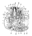
スプール軸16は、図6に示すように、側板5bを貫通して第2側カバー6bの外方に延びている。その延びた一端は、第2側カバー6bに形成されたボス部6cに玉軸受24aにより回転自在に支持されている。またスプール軸16の他端は、遠心ブレーキ機構23内で玉軸受24bにより回転自在に支持されている。玉軸受24a,24bは、それぞれ外輪34aと内輪34bと複数の転動体34cとリテーナ34dを有している。玉軸受24aの外輪34aはボス部(第1部品の一例)6cに装着され、内輪34bはスプール軸(第2部品の一例)16に装着されている。玉軸受24bの外輪34aはブレーキケース(第1部品の一例)65に装着され、内輪34bはスプール軸(第2部品の一例)16に装着されている。転動体34cは鋼球であり、外輪34aと内輪34bとに接触した状態で周方向に間隔を隔てて配置されている。リテーナ34dは、転動体34cを周方向に間隔を隔てて転動自在に保持するものである。外輪34a、内輪34b及び転動体34cは、たとえば低耐食性金属材料であるSUS440C製である。これらのステンレス鋼の表面には、高耐食性を有する濃化したクロム酸化物被膜を生成した後に生成した被膜の安定強化を図った表面改質処理による高耐食性被膜が形成されている。リテーナ34dは、たとえばナイロン等の高耐食性を有する合成樹脂製である。リテーナ34dもSUS440Cを使用して高耐食性被膜で覆うようにしてもよい。
【0027】
スプール軸16の大径部分16aの右端は、側板5bの貫通部部分に配置されており、そこにはクラッチ機構13を構成する係合ピン16bが固定されている。係合ピン16bは、直径に沿って大径部分16aを貫通しており、その両端が径方向に突出している。
【0028】
レベルワインド機構15は、図3に示すように、1対の側板5a,5b間に固定されたガイド筒25と、ガイド筒25内に回転自在に支持された螺軸26と、ラインガイド27とを有している。
【0029】
ガイド筒25は、後部周面が全長にわたり切り欠かれた円筒状の部材であり、ラインガイド27をスプール軸16の軸方向(釣り竿Rと直交する方向)に案内する。
【0030】
螺軸26は、図7に示すように、ラインガイド27をスプール軸16の軸方向に往復移動させるための軸である。螺軸26の両端は、側板5a,5bに設けられたボス部54a,54bに玉軸受39a,39bにより回転自在に支持されている。これらの玉軸受も前記した玉軸受24a,24bと同様な構成であり、高耐食性を有するものである。玉軸受39a,39bの外方、つまり内方の液体浸入方向の逆側には、ゴム製のシール部材53a,53bがボス部54a,54bにそれぞれ装着されている。シール部材53a,53bは、側板5a,5bの内側面から玉軸受39a,39bを通って浸入した液体がそれ以上リール本体1の内部に浸入するのを防止している。このようなシール部材53a,53bを装着することにより、真水をかけて軸受39a,39bを洗浄してもリール本体1内部に水が浸入しなくなる。螺軸26の端部には、ギア機構18を構成するギア28aが固定されている。また螺軸26には交差する螺旋状の溝26aが形成されている。
【0031】
ラインガイド27は、図5に示すように、ガイド本体27aと、ガイド本体27aに回転自在に装着された係止軸27bと、ガイド本体27aの上部に上方に突出して配置されたガイドリング27cとを有している。ガイド本体27aにはガイド筒25が貫通するU字状の貫通孔がスプール軸16に平行に形成されており、ガイド本体27aは、ガイド筒25に軸方向に移動自在に支持されている。係止軸27bは、ガイド本体27aの後部にほぼ前後に沿って配置され先端が螺軸26の溝26aに係止されている。係止軸27bは、螺軸26の回動により溝26aに沿って回動しガイド本体27aを往復移動させる。ガイドリング27cは、たとえばステンレス製の線材を上部を凸にヘアピン状に曲げて形成されており、内周側に長孔が形成されている。ガイドリング27cは、下部がガイド本体27aの後部上面に差し込まれて固定されている。ガイドリング27cの表面は、たとえば窒化チタン等の金属やSiC等のセラミックでコーティングされており、表面が滑らかで硬くなっている。なお、このガイドリング27cは、開口9とスプール12との間にスプール12に近接して配置されている。ガイドリング27cの上部は、下部にガイド溝が形成されたガイド軸25aによりスプール軸16に平行に案内されている。このガイド軸25aは、ガイド筒25の上方にガイド筒25と平行に配置されており、両端が側板5a,5bに固定されている。このように高さが高いガイドリング27cをスプール12に近接して配置することで、サムレスト8の前部8aの高さHを低くすることででき、パーミングしやすくなる。
【0032】
このレベルワインド機構15では、ギア機構18を介して螺軸26が回転させられることにより、ラインガイド27がガイド筒25に沿って往復動する。このラインガイド27のガイドリング27c内に釣り糸が挿通されて釣り糸がスプール12に均一に巻き付けられる。
【0033】
ギア機構18は、ハンドル軸30と、ハンドル軸30に固定されたメインギア31と、メインギア31に噛み合う筒状のピニオンギア32と、前述の螺軸26端部に固定されたギア28aと、ハンドル軸30に回転不能に固定され、ギア28aに噛み合うギア28bとを有している。このギア機構18のハンドル軸30の上下位置は、サムレスト8の高さを低くするために、従来の位置より低い。このため、ギア機構18を収納する側板5b及び第2側カバー6bの下部は、側板5a及び第1側カバー6aの下部より下方に位置している。ハンドル軸30の先端部は縮径されており、先端部の大径部及び小径部には平行な面取り部30aと雄ネジ部30bとがそれぞれが形成されている。
【0034】
ハンドル軸30の基端(図3左端)は、玉軸受57により側板5aに支持されている。この玉軸受57も前記同様な高耐食性を有するものである。玉軸受57の図6右側には、シール部材58が配置されている。このシール部材58もシール部材53a,53bと同様な構成であり、玉軸受57を真水により洗浄しても内部に真水が浸入しにくくなる。
【0035】
ピニオンギア32は、図6に示すように、側板5bの外方から内方に延び、中心にスプール軸16が貫通する筒状部材であり、スプール軸16に軸方向に移動自在に装着されている。また、ピニオンギア32の図6左端部は、玉軸受43により側板5bに回転自在かつ軸方向移動自在に支持されている。この玉軸受43も前記同様な構成である。玉軸受43の図6右側、つまり液体浸入側と逆側にもシール部材59が装着されている。
【0036】
ピニオンギア32は、図6右端側外周部に形成されメインギア31に噛合する歯部32aと、他端側に形成された噛み合い部32bと、歯部32aと噛み合い部32bとの間に形成されたくびれ部32cとを有している。噛み合い部32bは、ピニオンギア32の端面に直径に沿って形成された凹溝からなり、そこにスプール軸16を貫通して固定された係合ピン16bが係止される。ここではピニオンギア32が外方に移動してその噛み合い部32bとスプール軸16の係合ピン16bとが離脱すると、ハンドル軸30からの回転力はスプール12に伝達されない。この噛み合い部32bと係合ピン16bとによりクラッチ機構13が構成される。係合ピン16bと噛み合い部32bとが係合すると、スプール軸16より大径のピニオンギア32からスプール軸16にトルクが直接伝達されるので、ねじれ変形がより少なくなり、トルク伝達効率が向上する。
【0037】
クラッチレバー17は、図2に示すように、1対の側板5a,5b間の後部でスプール12後方に配置されている。フレーム5の側板5a,5bには長孔(図示せず)が形成されており、クラッチレバー17の回転軸17aがこの長孔に回転自在に支持されている。このため、クラッチレバー17は長孔に沿って上下方向にスライドすることも可能である。
【0038】
クラッチ係脱機構19は、図3に示すように、クラッチヨーク40を有している。クラッチヨーク40は、スプール軸16の外周側に配置されており、2本のピン41(一方のみ図示)によってスプール軸16の軸心と平行に移動可能に支持されている。なお、スプール軸16はクラッチヨーク40に対して相対回転が可能である。すなわち、スプール軸16が回転してもクラッチヨーク40は回転しないようになっている。またクラッチヨーク40はその中央部にピニオンギア32のくびれ部32cに係合する係合部40aを有している。またクラッチヨーク40を支持する各ピン41の外周で、クラッチヨーク40と第2側カバー6bとの間にはスプリング42が配置されており、クラッチヨーク40はスプリング42によって常に内方に付勢されている。
【0039】
このような構成で、通常状態では、ピニオンギア32は内方のクラッチ係合位置に位置しており、その噛み合い部32bとスプール軸16の係合ピン16bとが係合してクラッチオン状態となっている。一方、クラッチヨーク40によってピニオンギア32が外方に移動した場合には、噛み合い部32bと係合ピン16bとの係合が外れクラッチオフ状態となる。
【0040】
ドラグ機構21は、ドラグ力を調整操作するためのスタードラグ3と、メインギア31に押圧される摩擦プレート45と、スタードラグ3の回転操作によって摩擦プレート45をメインギア31に所定の力で押圧するための押圧プレート46とを有している。スタードラグ3は、回転操作すると発音する構成となっている。
【0041】
キャスティングコントロール機構22は、図3に示すように、スプール軸16の両端を挟むように配置された複数の摩擦プレート51と、摩擦プレート51によるスプール軸16の挟持力を調節するための制動キャップ52とを有している。右側の摩擦プレート51は、制動キャップ52内に装着され、左側の摩擦プレート51は、ブレーキケース65内に装着されている。制動キャップ52は回転操作すると発音する構成となっている。
【0042】
遠心ブレーキ機構23は、図3に示すように、ブレーキケース65と、ブレーキケース65内に設けられた回転部材66と、回転部材66に周方向に間隔を隔てて配置され径方向に移動自在に装着された摺動子67とを有している。ブレーキケース65の内周面には摺動子67に接触可能な筒状のブレーキライナー65aが固定されている。ブレーキケース65は、側板5aに形成された円形の開口5dに着脱自在に装着されており、第1側カバー6aとともに揺動する。
【0043】
次にリールの操作方法について説明する。
【0044】
通常の状態では、クラッチヨーク40はスプリング42によって内方(図3左方)に押されており、これによりピニオンギア32は、係合位置に移動させられている。この状態ではピニオンギア32の噛み合い部32bとスプール軸16の係合ピン16bとが噛み合ってクラッチオン状態となっており、ハンドル2からの回転力は、ハンドル軸30、メインギア31、ピニオンギア32及びスプール軸16を介してスプール12に伝達され、スプール12が糸巻き取り方向に回転する。
【0045】
キャスティングを行う場合には、バックラッシュを抑えるために制動力を調整する。ここでは、たとえばルアー(仕掛け)の質量に応じて制動力を調整するのが好ましい。具体的には、ルアーの質量が大きい場合には制動力を大きくし、小さい場合には小さくする。バックラッシュを抑えるための制動力の調整は、キャスティングコントロール機構22又は遠心ブレーキ機構23で行う。
【0046】
制動力を調整し終わると、クラッチレバー17を下方に押す。ここでは、クラッチレバー17は、側板5a,5bの長孔に沿って下方の離脱位置に移動する。そしてクラッチレバー17の移動により、クラッチヨーク40が外方に移動し、クラッチヨーク40に係合したピニオンギア32も同方向に移動させられる。この結果、ピニオンギア32の噛み合い部32bとスプール軸16の係合ピン16bとのかみあいが外れ、クラッチオフ状態となる。このクラッチオフ状態では、ハンドル軸30からの回転はスプール12及びスプール軸16に伝達されず、スプール12は自由回転状態になる。クラッチオフ状態として、クラッチレバー17においた親指でスプールをサミングしながらスプール軸16が鉛直面に沿うようにリールを軸方向に傾けて釣り竿を振ると、ルアーが投げられスプール12が糸繰り出し方向に回転する。
【0047】
このような状態では、スプール12の回転によりスプール軸16が糸繰り出し方向に回転し、その回転が回転部材66に伝達される。回転部材66が回転すると、摺動子67がブレーキライナー65aに摺接して遠心ブレーキ機構23によりスプール12が制動される。同時に、スプール軸16がキャスティングコントロール機構22により制動されバックラッシュを防止できる。
【0048】
仕掛けが着水すると、ハンドル2を回転させる。すると図示しないリターン機構によりクラッチオン状態になる。この状態でたとえばリトリーブを繰り返して魚の当たりを待つ。魚がヒットするとハンドル2を回転させて釣り糸を巻き取る。このとき、魚の大きさによりドラグ力を調整する必要が生じることがある。このときには、スタードラグ3を時計回り又は反時計回りに回転させてドラグ力を調整する。
【0049】
ここでは、外部から液体が浸入する位置に配置された玉軸受に対してはその奥側(液体浸入側と逆側)にシール部材を配置したので、真水で軸受を洗浄しても洗浄液がリール本体内部に入らなくなり、リール本体内部の各部の腐食を防止できる。また、玉軸受自体の耐食性能を高めたので玉軸受が腐食しにくくなる。さらに、特に回転性能が必要なスプール軸16を支持する玉軸受24a,24bにはシール部材を設けずに耐食性だけを向上させたので、回転性能の低下を抑えることができる。
【0050】
〔実施形態2〕
前記実施形態1では釣り用リールとして両軸受リールを例示したが、スピニングリール等の他の釣り用リールにも本発明は適用できる。
図8において、本発明の一実施形態を採用したスピニングリールは、ハンドル101と、ハンドル101を回転自在に支持するリール本体102と、ロータ103と、スプール104とを備えている。ロータ103は、リール本体102の前部に回転自在に支持されている。スプール104は、釣り糸を外周面に巻き取るものであり、ロータ103の前部に前後移動自在に配置されている。
【0051】
ハンドル101は、図8及び図10に示すように、T字状の把手部101aと、先端に把手部101aが回転自在に装着されたL字状のクランクアーム101bと、クランクアーム101bの基端に固定された軸部101cとを有している。クランクアーム101bは、基端側においてワンタッチで折れ曲がり可能である。軸部101cは、図9に示すように断面が矩形の棒状部材である。なお、ハンドル101は、図8に示す右位置と、図10に示す左位置との左右どちらの装着位置でもリール本体102に装着可能である。
【0052】
リール本体102は、側部に開口102cを有するリールボディ102aと、リールボディ102aから斜め上前方に一体で延びるT字状の竿取付脚102bと、リールボディ102aの開口102cを閉塞するための蓋体102dとを有している。
【0053】
リールボディ102aは、図9に示すように、内部に空間を有しており、その空間内には、ロータ103をハンドル101の回転に連動して回転させるロータ駆動機構105と、スプール104を前後に移動させて釣り糸を均一に巻き取るためのオシレーティング機構106とが設けられている。
【0054】
図10に示すように、リールボディ102aの図4右側面には、筒状のボス部117aが形成されている。ボス部117aは、ハンドル軸110(後述)の図4右端を支持する玉軸受116aを収納するためにリールボディ102aの内方に突出して形成されている。蓋体102dのボス部117aに対向する位置には、ボス部117bが形成されている。ボス部117bはハンドル軸110の図4左端を支持する玉軸受116bを収納するためにリールボディ102aの外方に突出して形成されている。ハンドル101が装着された側と逆側のボス部(図4ではボス部117a)は、軸カバー119により閉塞されている。ハンドル101が装着された側のボス部(図4ではボス部117b)は、孔あきカバー119bにより水の侵入が防止されている。軸カバー119及び孔あきカバー119bは、図8に示すように、楕円形の部材であり、それぞれ2本のビス119aによりボス部に取り付けられる。これらの玉軸受116a,116bも前記同様に高耐食性を有するものである。ただし、これらの玉軸受の液体浸入側と逆側(玉軸受の内側)にシール部材を設けていない。これは、軸カバー119及び孔あきカバー119bをあけて真水で軸受116a,116bも含めてリール本体102内部を洗浄できるようにするためである。このような洗浄を行っても玉軸受116a,116bが高耐食性を有しているので腐食しにくくなる。
【0055】
ロータ駆動機構105は、ハンドル101が回転不能に装着されたハンドル軸110と、ハンドル軸110とともに回転するフェースギア111と、このフェースギア111に噛み合うピニオンギア112とを有している。ハンドル軸110の両端は、玉軸受116a,116bを介してリールボディ102aに回転自在に支持されている。ハンドル軸110の中心部には断面が矩形の貫通孔110aが形成されており、この貫通孔110aにハンドル101の軸部101cが回転不能に挿入される。軸部101cの先端面にはネジ孔101dが形成されており、このネジ孔101dに螺合する取付ネジ120によりハンドル101がハンドル軸110に取り付けられている。
【0056】
ピニオンギア112は筒状に形成されており、図9に示すように、その前部112aはロータ3の中心部を貫通しており、ナット113によりロータ103と固定されている。ピニオンギア112は、その軸方向の中間部と後端部とが、それぞれ玉軸受114a,114bを介してリール本体102に回転自在に支持されている。この玉軸受114a,114bも前記同様に高耐食性を有するものである。
【0057】
オシレーティング機構106は、スプール104の中心部にドラグ機構160を介して連結されたスプール軸115を前後方向に移動させてスプール104を同方向に移動させるための機構である。オシレーティング機構106は、スプール軸115の略直下方に平行に配置された螺軸121と、螺軸121に沿って前後方向に移動するスライダ122と、螺軸121の先端に固定された中間ギア123とを有している。スライダ122にはスプール軸115の後端が回転不能に固定されている。中間ギア123は、ピニオンギア112に噛み合っている。
【0058】
ロータ103は、図9に示すように、円筒部130と、円筒部130の側方に互いに対向して設けられた第1及び第2ロータアーム131,132とを有している。円筒部130と両ロータアーム131,132とは、たとえばアルミニウム合金製であり一体成形されている。
【0059】
円筒部130の前部には前壁133が形成されており、前壁133の中央部にはボス部133aが形成されている。ボス部133aの中心部には貫通孔が形成されており、この貫通孔をピニオンギアの前部112a及びスプール軸115が貫通している。前壁133の前部にナット113が配置されており、ナット113の内部にスプール軸115を回転自在に支持する玉軸受135が配置されている。この玉軸受135も前記同様に高耐食性を有するものである。
【0060】
第1ロータアーム131の先端の外周側には、第1ベール支持部材140が揺動自在に装着されている。第1ベール支持部材140は、第1ロータアーム131にねじ込まれた取付ピンにより第1ロータアーム131に取り付けられる。第1ベール支持部材140の先端には、釣り糸をスプール104に案内するためのラインローラ141と、ラインローラ141を挟んで第1ベール支持部材140に固定された固定軸カバー147とが装着されている。ラインローラ141は、第1ベール支持部材140の先端に回転自在に装着されている。固定軸カバー147は、先端がとがった変形円錐形状である。
【0061】
固定軸カバー147の先端部と第2ベール支持部材142との間には線材を略U状に湾曲させた形状のベール143が固定されている。これらの第1及び第2ベール支持部材140,142、ラインローラ141、ベール143及び固定軸カバー147により釣り糸をスプール104に案内するベールアーム144が構成される。ベールアーム144は、図9に示す糸案内姿勢とそれから反転した糸開放姿勢との間で揺動自在である。
【0062】
第1ベール支持部材140の外周側にはカバー145が装着されており、カバー145の内部にはベールアーム144を糸開放姿勢から糸案内姿勢にロータ103の回転に連動して復帰させるとともに、両姿勢でその状態を保持するベール反転機構146が配置されている。
【0063】
ロータ103の円筒部130の内部にはロータ103の逆転を禁止・解除するための逆転防止機構150が配置されている。逆転防止機構150は、内輪が遊転するローラ型のワンウェイクラッチ151と、ワンウェイクラッチ151を作動状態(逆転禁止状態)と非作動状態(逆転許可状態)とに切り換える切換機構152とを有している。
【0064】
スプール104は、ロータ103の第1ロータアーム131と第2ロータアーム132との間に配置されており、スプール軸115の先端にドラグ機構160を介して装着されている。スプール104は、外周に釣り糸が巻かれる糸巻き胴部104aと、糸巻き胴部104aの後部に一体で形成されたスカート部104bと、糸巻き胴部104aの前端に固定されたフランジ板104cとを有している。糸巻き胴部104aは、ストレートな円筒状の部材であり、外周面はスプール軸115と平行な周面で構成されている。糸巻き胴部104aは、2つの軸受156,157によりスプール軸115に回転自在に装着されている。フランジ板104cは、糸巻き胴部104aの内周面にネジ止めされたスプールリングカラー155により糸巻き胴部104aに固定されている。
【0065】
次に、スピニングリールの操作及び動作について説明する。
【0066】
キャスティング時には、ハンドル101を図10に示すたとえば左位置に装着した状態でベールアーム144を糸開放姿勢に反転させる。これにより第1ベール支持部材140及び第2ベール支持部材142は揺動する。この状態で釣り竿を握る手の人差し指で釣り糸を引っかけながら釣り竿をキャスティングする。すると釣り糸は仕掛けの重さにより勢いよく放出される。この状態でハンドル101をたとえば左手で糸巻取方向に回転させると、ロータ駆動機構105によりロータ103が糸巻取方向に回転し、ベールアーム144がベール反転機構146により糸巻取位置に復帰し釣り糸がスプール104に巻き付けられる。
【0067】
ハンドル101を糸巻取方向に回転させるとフェースギア111,ピニオンギア112を介してロータ103が糸巻取方向に回転し、ベールアーム144に案内された釣り糸がスプール104の外周に巻き付けられる。ハンドル軸110にシールをモータいけていないので、ハンドル軸110の回転性能が低下しにくい。このため、ハンドル101を回転させると軽い力でロータ103を回転させることができる。
【0068】
洗浄するときには、軸カバー119及び孔あきカバー119aを外し、さらにハンドル101を外す。そして、軸受116a,116bの内輪の中心孔から真水をリール本体102内部に入れて洗浄する。そして、最後に内部の水を抜いてさらに水を拭き取って乾燥させる。ここでは、軸受を高耐食性にしたので、真水で洗浄しても腐食しにくくなる。
【0069】
〔実施形態3〕
図11において、本発明の実施形態3を採用したトローリングリールは、筒状のリール本体201と、リール本体201の中心部に軸方向移動自在かつ回転不能に装着されたスプール軸202と、スプール軸202に回転自在かつ軸方向移動不能に支持されたスプール203と、リール本体201の側方に配置されたハンドル204とを備えている。また、トローリングリールは、ハンドル204の回転をスプール203に伝達するギア変速機構206及びスプール203を制動するドラグ機構207をリール本体201の内部に備えている。
【0070】
リール本体201は、円板状の側板210と、側板210がいんろう結合により同芯に結合され、ネジにより固定されたリールボディ211とを有している。側板210は、そのほぼ中心部で回動不能かつ軸方向に移動可能にスプール軸202の端部を支持する。また、中心孔にはスプール軸202の一端に外方に突出して形成された係止ピン202aを係止する係止溝210bが形成されている。この係止ピン202aと係止溝210bとの係合によりスプール軸202がリール本体201に対して回転不能になる。
【0071】
リールボディ211は、合成樹脂又はアルミニウムダイキャストにより一体的に形成された有底円筒状の部材である。リールボディ211は、側板210が固定されるリング状の固定部211aと、固定部211aに間隔を隔てて対向して配置され、スプール軸202やハンドル204により回転するハンドル軸205を支持する円板状の支持部211bと、固定部211aと支持部211bとを円周方向の4か所で連結する連結部211cとを有している。支持部211bは、スプール軸202の他端をその中心部で軸方向に移動可能に支持する第1ボス部211dと、第1ボス部211dの下方に設けられハンドル軸205を回転自在に支持する第2ボス部11eとを有している。また、支持部211bの下部には、ギア機構206を収納するために径方向に膨出した膨出部211fが形成されている。
【0072】
連結部211cにおいて、上部にはリールハーネスに装着するためのハーネスラグ212が間隔を隔てて装着されており、下部にはリールを釣り竿に装着するための竿取付部213が設けられている。
【0073】
スプール軸202は、軸方向に間隔を隔てて配置された2つの玉軸受232によりスプール203を回転自在に支持する。この玉軸受232も前記同様に高耐食性を有するものである。スプール軸232の左側の玉軸受232の左側には皿バネ233が当接している。また、右側の玉軸受232の右側にはスプール軸202をハンドル204と逆側に付勢するコイルバネ238が当接している。
【0074】
スプール203は、胴部203aと胴部203aの両端に一体形成された1対のフランジ部203bとを有している。左側のフランジ部203bの端面には、音出しギア235が設けられている。この音出しギア235には側板210に取り付けられたC字状のバネ部材237に支持された係合爪236が係合しており、スプール203が回転するとクリック音が発生する。
【0075】
スプール203の右側のフランジ部203bの端面には、ドラグ機構207を構成する摩擦板226が相対回転不能に固定されている。
【0076】
ハンドル204は、スプール軸202の下方にスプール軸202と平行に配置された筒状のハンドル軸205の突出端に固定されている。ハンドル軸205は、第2ボス部211eでリールボディ211に回転自在に支持されている。
【0077】
ギア変速機構206は、ハンドル軸205の回転を高低2速のいずれかに変速してドラグ機構207に伝達する。
【0078】
ドラグ機構207は、前記摩擦板226と、摩擦板226に圧接するドラグディスク227と、スプール軸202をスプール203とともに軸方向に移動させるドラグ操作機構214とを有している。
【0079】
ドラグディスク227は、摩擦板226に圧接可能なディスク本体227aと、ディスク本体227aの内周部に回転不能に装着された伝動部材228とを備えている。伝動部材228は、ギア機構206に連結されており、ギア機構206とともに回転する。ドラグディスク227は、ドラグカバー224によりカバーされている。ドラグカバー224は、内周部が伝動部材228の外周側に配置されており、外周部がパッキン223を介してスプール202の右側のフランジ部203bにねじ込み固定されている。伝動部材228は、玉軸受221によりスプール軸202に回転自在に支持されている。この玉軸受221も前記同様に高耐食性を有するものである。
【0080】
ドラグ操作機構214は、スプール軸202のハンドル204側端部にネジ止めされた回動ネジ230と、回動ネジ230に当接するカム体229と、カム体229とリールボディ211の第1ボス部211d端面との間に配置されたドラグレバー231とを有している。カム体229はスプール軸202と同芯上に配置されており、その回動ネジ230との当接面と逆側にはドラグレバー231と接触するカム面229aが形成されている。ドラグレバー231は、第1ボス部211dに揺動自在に支持されており、そのカム面229aとの接触面にはカム面231aが形成されている。これらのカム面229a,231aは、乗り上げ型に構成されており、ドラグレバー231が揺動するとスプール軸202がリール本体201に対して軸方向にスライドする。
【0081】
次に、上述のトローリングリールの操作方法について説明する。
【0082】
ドラグ機構207の摩擦力を調節する際には、回動ノブ230によってスプール軸202の軸方向の位置を適当に設定しておき、ドラグレバー231を操作することで、たとえば、スプール軸202をハンドル204側に移動させた場合には、スプール203がドラグディスク227側に移動する結果、摩擦力が増大する。逆にスプール軸202をハンドル204と逆側に移動させた場合には、スプール203がドラグディスク227から離れる方向に移動する結果、摩擦力が低減する。そして、スプール203の摩擦板226がドラグディスク227から完全に離れると、スプール203が逆転許可される。
ここでは、玉軸受を高耐食性を有するものにしたので、回転性能を維持して耐食性を向上できる。
【0083】
〔実施形態4〕
図12において、本発明の実施形態4を採用した電動リールのモータ243は、出力軸と逆側の端部でモータケース250を介してリール本体240に装着されている。モータケース250は、スプール242の内部に配置されている。モータケース250とスプール242との間には玉軸受251が配置されている。軸受251の液体が浸入する側と逆側(図12右側)にはシール部材252が装着されている。このシール部材252も実施形態1の螺軸26に装着されたものと同様な構成である。
【0084】
このように、電動リールのモータを支持する軸受の液体が浸入する側と逆側をシール部材252でシールすれば、軸受の洗浄を可能にしてモータの故障を防止できる。
【0085】
〔他の実施形態〕
(a)前記実施形態では、ベイトリール、フロントドラグ型スピニングリール、レバードラグ型両軸受リール、電動リールを例に説明したが、本発明はこれらのリールに限定されるものではなく、レバーブレーキ型のスピニングリールなどの他の形式のスピニングリール、カウンター付きの両軸受リール等の他の両軸受リール、片軸受リール等全ての釣り用リールに適用できる。特に海釣りに使用されるリールに好適である。
【0086】
(b)前記実施形態では、玉軸受の外輪と内輪と転動体とを高耐食性被膜を形成したSUS440Cで構成し、軸受全体を高耐食性を有するものにしたが、少なくとも転動体だけを高耐食性を有するものにしてもよい。また、転動体に加えて回転側の外輪又は内輪だけを高耐食性を有するものにしてもよい。さらに、リテーナを耐食性を有するものにしてもよい。
【0087】
(c)前記実施形態では、高耐食製被膜を形成したが、高耐食性被膜を形成せずに母材自体を高耐食性にしてもよい。たとえば、母材をアルミナセラミックやSiCセラミック等の高耐食性を有するセラミック製にしたり、SUS304,316,630等の高耐食性を有するステンレス製にしたり、チタンやボロンなどの高耐食性を有する金属にしてもよい。
【0088】
(d)前記実施形態では、転がり軸受として玉軸受を例に説明したが、本発明は、円筒ころ軸受や針状ころ軸受や他の形式の全ての釣り用リールの転がり軸受に適用できる。また、転がり軸受を兼用したローラ型のワンウェイクラッチにも適用できる。
【0089】
【発明の効果】
本発明によれば、少なくとも転動体が耐食材料製または耐食被膜で被覆された金属製であるので、回転中は常に転がる転動体の耐蝕性が高くなる。このため、軸受全体の耐食性が向上する。また、耐食性が向上するので腐食を防止するためのシール部材を設ける必要がなくなる。このため、回転性能の低下を抑えることができる。
【0090】
別の発明によれば、海水等が浸入しても軸受が腐食しにくいとともに、洗浄用の水などが軸受に浸入可能になり、海水で汚れた軸受を簡単に洗浄できる。しかも、軸受の奥側にシール部材が装着されているので、液体がそれ以上奥に浸入しなくなり、内部部品の腐食を防止できる。
【図面の簡単な説明】
【図1】 本発明の実施形態1を採用した両軸受リールの斜視図。
【図2】 その平面図。
【図3】 その横断面図。
【図4】 その正面図。
【図5】 図4のV−V断面図。
【図6】 スプール軸周辺の断面拡大図。
【図7】 螺軸周辺の断面拡大図。
【図8】 本発明の実施形態2を採用したスピニングリールの側面図。
【図9】 その断面図。
【図10】 その背面断面図。
【図11】 本発明の実施形態3を採用したトローリングリールの側面図。
【図12】 本発明の実施形態4を採用した電動リールのモータ装着部分の断面図。
【符号の説明】
1 リール本体
5a,5b 側板
6c ボス部
16 スプール軸
24a,24b,
26 螺軸
34a 外輪
34b 内輪
34c 転動体
34d リテーナ
53a,53b,58,59,252 シール部材[0001]
BACKGROUND OF THE INVENTION
The present invention , Department Product support structure, in particular, a fishing reel provided between a first part that rotates relative to a fishing reel such as a spinning reel or a double-bearing reel and a second part that is disposed on the inner peripheral side of the first part. Part of The product support structure.
[0002]
[Prior art]
2. Description of the Related Art Fishing reels such as spinning reels and double-bearing reels often use rotating parts such as a rotor, a spool, and a handle shaft that rotate relative to the reel body and other parts. This type of rotating component is rotatably mounted on the reel body and other components by bearings. In the case of fishing reels as bearings for supporting the rotating parts, ball bearings are often used.
[0003]
Generally, since fishing reels are used in an atmosphere where moisture adheres and is easily corroded, it is desired to improve the corrosion resistance of ball bearings. Conventionally, in order to improve the corrosion resistance of ball bearings, stainless steel, which does not easily rust, has been used as a material for ball bearings used for fishing reels used in sea fishing. Among these stainless steels, SUS440C that can be hardened is often used for rolling elements of ball bearings in consideration of rotational performance and cost. In other words, SUS440C has high strength and sufficient impact resistance in terms of specifications as a bearing and can maintain high processing accuracy, so that it can maintain high rotational performance. However, SUS440C has a problem that it is harder but less corrosion-resistant than austenitic materials such as SUS304 and SUS316. For this reason, it is better to make the bearing itself waterproof to prevent corrosion. In order to make the bearing waterproof, a rubber seal type ball bearing in which a rubber seal member is mounted between the inner ring and the outer ring so as to come into contact with both is often used. In a rubber seal type ball bearing, a seal member is mounted at least on the liquid ingress side of the ball bearing.
[0004]
[Problems to be solved by the invention]
If the corrosion of the bearing is prevented by the shield bearing, the seal member comes into contact with the inner and outer rings, so that the rotational load is increased and the rotational performance is deteriorated. In order to maintain the rotation performance, a non-contact seal member may be used. However, the non-contact seal member has poor seal performance, and the corrosion resistance is not sufficient particularly for use in a fishing reel for sea fishing.
[0005]
On the other hand, disposing the seal member on the liquid ingress side is effective in preventing corrosion. However, for example, when water is washed with a hose after sea fishing, the bearing cannot be washed because water does not enter the bearing. Cleaning is possible without providing a sealing member, but cleaning water may enter the inside of the reel and cause corrosion and saltiness of internal parts.
[0006]
An object of the present invention is to improve the corrosion resistance of a bearing by suppressing a decrease in rotational performance.
[0007]
Another object of the present invention is to facilitate cleaning of the bearing without causing corrosion of internal parts.
[0008]
[Means for Solving the Problems]
A fishing reel component support structure according to a first aspect of the present invention is a structure that supports a first component of a fishing reel and a second component arranged on the inner peripheral side of the first component so as to be relatively rotatable, And a sealing member. The bearing is arranged at a position where liquid can enter from the outside. The bearing includes an outer ring, an inner ring, and a plurality of rolling elements. The outer ring is attached to the first part. The inner ring is mounted on the second part and arranged with a gap from the outer ring. The plurality of rolling elements are disposed between both wheels in contact with both wheels and spaced apart in the circumferential direction. Of the inner ring, outer ring, and rolling element, at least the rolling element is made of a corrosion-resistant material or a metal coated with a corrosion-resistant coating. The seal member is a member that is arranged on the opposite side to the liquid intrusion side from the bearing and seals the gap between the two parts. In this case, the bearing is not easily corroded even when seawater or the like enters, and cleaning water or the like can enter the bearing, so that the bearing contaminated with seawater can be easily cleaned. In addition, since the seal member is mounted on the back side of the bearing, the liquid does not enter further into the back, and corrosion of internal parts can be prevented.
[0009]
Further, in the bearing, when the two parts rotate relative to each other, the inner ring and the outer ring rotate relative to each other, and the rolling element rolls at an interval while rotating and revolving while contacting the both. Here, since at least the rolling elements are made of a corrosion-resistant material or a metal coated with a corrosion-resistant coating, the corrosion resistance of the rolling elements that always roll during rotation increases. For this reason, the corrosion resistance of the whole bearing improves. Further, since the corrosion resistance is improved, there is no need to provide a seal member for preventing corrosion. For this reason, the fall of rotational performance can be suppressed.
[0010]
A fishing reel component support structure according to a second aspect of the present invention is a structure that supports a first component of a fishing reel and a second component arranged on the inner peripheral side of the first component so as to be relatively rotatable, And a sealing member. The bearing is arranged at a position where liquid can enter from the outside. The bearing includes an outer ring, an inner ring, and a plurality of rolling elements. The outer ring is attached to the first part. The inner ring is mounted on the second part and arranged with a gap from the outer ring. The plurality of rolling elements are disposed between both wheels in contact with both wheels and spaced apart in the circumferential direction. Of the inner ring, outer ring, and rolling element, at least the rolling element is made of a corrosion-resistant material or a metal coated with a corrosion-resistant coating. The seal member is disposed on the opposite side to the liquid intrusion side from the rolling element, and seals the gap between the two wheels. In this case, the bearing is not easily corroded even when seawater or the like enters, and cleaning water or the like can enter the bearing, so that the bearing contaminated with seawater can be easily cleaned. In addition, since the seal member is mounted on the back side of the rolling element, the liquid does not enter deeper further, and corrosion of internal parts can be prevented.
[0011]
Further, in the bearing, when the two parts rotate relative to each other, the inner ring and the outer ring rotate relative to each other, and the rolling element rolls at an interval while rotating and revolving while contacting the both. Here, since at least the rolling elements are made of a corrosion-resistant material or a metal coated with a corrosion-resistant coating, the corrosion resistance of the rolling elements that always roll during rotation increases. For this reason, the corrosion resistance of the whole bearing improves. Further, since the corrosion resistance is improved, there is no need to provide a seal member for preventing corrosion. For this reason, the fall of rotational performance can be suppressed.
[0012]
The fishing reel according to the
[0013]
The fishing reel according to the invention 4 Component support structure Is described in any one of the
[0014]
The fishing reel according to the
[0015]
The fishing reel according to the
[0016]
The fishing reel according to the
[0017]
DETAILED DESCRIPTION OF THE INVENTION
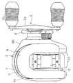
1 and 2, the dual-bearing reel in which an embodiment of the present invention is adopted is a low profile type reel for bait casting. The reel includes a
[0018]
The
[0019]
As shown in FIG. 3, the
[0020]
As shown in FIG. 3, the
[0021]
The
[0022]
As shown in FIGS. 4 and 5, the
[0023]
As shown in FIGS. 1, 2, and 4, the
[0024]
In the
[0025]
The
[0026]
As shown in FIG. 6, the
[0027]
The right end of the large-
[0028]
As shown in FIG. 3, the
[0029]
The
[0030]
As shown in FIG. 7, the
[0031]
As shown in FIG. 5, the
[0032]
In the
[0033]
The
[0034]
The base end (left end in FIG. 3) of the
[0035]
As shown in FIG. 6, the
[0036]
The
[0037]
As shown in FIG. 2, the
[0038]
As shown in FIG. 3, the clutch engagement /
[0039]
With such a configuration, in the normal state, the
[0040]
The
[0041]
As shown in FIG. 3, the
[0042]
As shown in FIG. 3, the
[0043]
Next, a method for operating the reel will be described.
[0044]
In a normal state, the
[0045]
When casting, the braking force is adjusted to suppress backlash. Here, for example, the braking force is preferably adjusted according to the mass of the lure (device). Specifically, the braking force is increased when the mass of the lure is large, and is decreased when the mass of the lure is small. Adjustment of the braking force for suppressing backlash is performed by the
[0046]
When the braking force is adjusted, the
[0047]
In such a state, rotation of the
[0048]
When the device lands, the
[0049]
Here, since the seal member is arranged on the back side (the opposite side to the liquid ingress side) with respect to the ball bearing arranged at the position where the liquid enters from the outside, the cleaning liquid remains on the reel even if the bearing is washed with fresh water. It will not enter the main body, and corrosion of each part inside the reel main body can be prevented. Further, since the corrosion resistance of the ball bearing itself is increased, the ball bearing is less likely to corrode. In addition, since the
[0050]
[Embodiment 2]
Although the double-bearing reel is exemplified as the fishing reel in the first embodiment, the present invention can be applied to other fishing reels such as a spinning reel.
In FIG. 8, a spinning reel adopting an embodiment of the present invention includes a
[0051]
As shown in FIGS. 8 and 10, the
[0052]
The
[0053]
As shown in FIG. 9, the
[0054]
As shown in FIG. 10, a cylindrical boss portion 117a is formed on the right side of FIG. 4 of the
[0055]
The
[0056]
The
[0057]
The
[0058]
As shown in FIG. 9, the
[0059]
A front wall 133 is formed at the front portion of the
[0060]
A first
[0061]
A
[0062]
A
[0063]
A reverse
[0064]
The
[0065]
Next, the operation and operation of the spinning reel will be described.
[0066]
At the time of casting, the
[0067]
When the
[0068]
When cleaning, the
[0069]
[Embodiment 3]
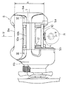
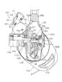
In FIG. 11, a trolling
[0070]
The reel
[0071]
The
[0072]
In the connecting
[0073]
The
[0074]
The
[0075]
A
[0076]
The
[0077]
The
[0078]
The
[0079]
The
[0080]
The
[0081]
Next, a method for operating the above trolling reel will be described.
[0082]
When adjusting the frictional force of the
Here, since the ball bearing has high corrosion resistance, the rotational performance can be maintained and the corrosion resistance can be improved.
[0083]
[Embodiment 4]
In FIG. 12, a
[0084]
In this way, if the sealing
[0085]
[Other Embodiments]
(A) In the above embodiment, bait reels, front drag type spinning reels, lever drag type dual bearing reels, and electric reels have been described as examples. However, the present invention is not limited to these reels, and lever brake type The present invention can be applied to all types of fishing reels such as other types of spinning reels such as spinning reels, other double bearing reels such as a double bearing reel with a counter, and single bearing reels. It is particularly suitable for reels used for sea fishing.
[0086]
(B) In the above embodiment, the outer ring, the inner ring, and the rolling element of the ball bearing are made of SUS440C having a high corrosion resistance coating, and the entire bearing has high corrosion resistance. However, at least only the rolling element has high corrosion resistance. You may have. In addition to the rolling elements, only the outer ring or inner ring on the rotating side may have high corrosion resistance. Further, the retainer may have corrosion resistance.
[0087]
(C) Although the highly corrosion-resistant coating film is formed in the embodiment, the base material itself may be made highly corrosion-resistant without forming the high corrosion-resistant coating film. For example, the base material is made of a ceramic having high corrosion resistance such as alumina ceramic or SiC ceramic, made of stainless steel having high corrosion resistance such as SUS304, 316, 630, or a metal having high corrosion resistance such as titanium or boron. Good.
[0088]
(D) In the above embodiment, a ball bearing has been described as an example of a rolling bearing, but the present invention can be applied to a cylindrical roller bearing, a needle roller bearing, and all other types of fishing reel rolling bearings. The present invention can also be applied to a roller type one-way clutch that also serves as a rolling bearing.
[0089]
【The invention's effect】
According to the present invention, since at least the rolling elements are made of a corrosion-resistant material or a metal coated with a corrosion-resistant coating, the corrosion resistance of the rolling elements that always roll during rotation increases. For this reason, the corrosion resistance of the whole bearing improves. Further, since the corrosion resistance is improved, there is no need to provide a seal member for preventing corrosion. For this reason, the fall of rotational performance can be suppressed.
[0090]
According to another invention, even if seawater or the like enters, the bearing is not easily corroded, and cleaning water or the like can enter the bearing, so that the bearing contaminated with seawater can be easily cleaned. In addition, since the seal member is mounted on the back side of the bearing, the liquid does not enter further into the back, and corrosion of internal parts can be prevented.
[Brief description of the drawings]
FIG. 1 is a perspective view of a dual-bearing
FIG. 2 is a plan view thereof.
FIG. 3 is a cross-sectional view thereof.
FIG. 4 is a front view thereof.
5 is a cross-sectional view taken along line VV in FIG.
FIG. 6 is an enlarged cross-sectional view around the spool shaft.
FIG. 7 is an enlarged sectional view around a screw shaft.
FIG. 8 is a side view of a spinning
FIG. 9 is a cross-sectional view thereof.
FIG. 10 is a rear sectional view thereof.
FIG. 11 is a side view of a trolling
FIG. 12 is a cross-sectional view of a motor mounting portion of an electric reel adopting Embodiment 4 of the present invention.
[Explanation of symbols]
1 Reel body
5a, 5b side plate
6c Boss
16 Spool shaft
24a, 24b,
26 Screw shaft
34a outer ring
34b inner ring
34c rolling element
34d retainer
53a, 53b, 58, 59, 252 Seal member
Claims (7)
前記第1部品に装着された外輪と、前記第2部品に装着され前記外輪と隙間をあけて配置された内輪と、前記両輪の間に前記両輪と接触して周方向に間隔を隔てて配置された複数の転動体とを備え、外部から液体が浸入可能な位置に配置された軸受と、
前記軸受より液体浸入側と逆側に配置され、前記両部品の隙間をシールするシール部材と、を備え、
前記内輪、外輪、及び転動体のうち少なくとも転動体は耐食性材料製又は耐食性被膜で被覆された金属材料製である、釣り用リールの部品支持構造。A fishing reel component support structure that supports a first component of a fishing reel and a second component disposed on the inner peripheral side of the first component so as to be relatively rotatable,
An outer ring mounted on the first part, an inner ring mounted on the second part and arranged with a gap from the outer ring, and a contact between the two wheels and the circumferentially spaced arrangement between the two wheels A plurality of rolling elements, and a bearing disposed at a position where liquid can enter from the outside,
A seal member that is disposed on the opposite side of the bearing from the liquid ingress side and seals the gap between the two parts; and
A fishing reel component support structure, wherein at least the rolling elements of the inner ring, the outer ring, and the rolling elements are made of a corrosion-resistant material or a metal material coated with a corrosion-resistant coating.
前記第1部品に装着された外輪と、前記第2部品に装着され前記外輪と隙間をあけて配置された内輪と、前記両輪の間に前記両輪と接触して周方向に間隔を隔てて配置された複数の転動体とを備え、外部から液体が浸入可能な位置に配置された軸受と、
前記転動体より液体浸入側と逆側に配置され、前記両輪の隙間をシールするシール部材と、を備え、
前記内輪、外輪、及び転動体のうち少なくとも転動体は耐食性材料製又は耐食性被膜で被覆された金属材料製である、釣り用リールの部品支持構造。A fishing reel component support structure that supports a first component of a fishing reel and a second component disposed on the inner peripheral side of the first component so as to be relatively rotatable,
An outer ring mounted on the first part, an inner ring mounted on the second part and arranged with a gap from the outer ring, and a contact between the two wheels and the circumferentially spaced arrangement between the two wheels A plurality of rolling elements, and a bearing disposed at a position where liquid can enter from the outside,
A seal member that is disposed on the opposite side to the liquid entry side from the rolling element, and seals the gap between the two wheels,
A fishing reel component support structure, wherein at least the rolling elements of the inner ring, the outer ring, and the rolling elements are made of a corrosion-resistant material or a metal material coated with a corrosion-resistant coating.
Priority Applications (12)
| Application Number | Priority Date | Filing Date | Title |
|---|---|---|---|
| JP2000300369A JP3961757B2 (en) | 2000-09-29 | 2000-09-29 | Parts support structure for fishing reel |
| PCT/JP2001/007972 WO2002028177A1 (en) | 2000-09-29 | 2001-09-13 | Fishing reel bearing and component support structure |
| AU8623601A AU8623601A (en) | 2000-09-29 | 2001-09-13 | Fishing reel bearing and component support structure |
| CNB018164854A CN1226917C (en) | 2000-09-29 | 2001-09-13 | Fishing reel braring and component support structure |
| EP01965633A EP1320294B1 (en) | 2000-09-29 | 2001-09-13 | Fishing reel bearing and component support structure |
| DE60124276T DE60124276T2 (en) | 2000-09-29 | 2001-09-13 | WAREHOUSE AND COMPONENT STRUCTURE STORAGE |
| BRPI0114290-9A BR0114290B1 (en) | 2000-09-29 | 2001-09-13 | Component support frame and fishing reel holder. |
| KR1020037004591A KR100791733B1 (en) | 2000-09-29 | 2001-09-13 | Fishing reel bearing and component support structure |
| AU2001286236A AU2001286236B9 (en) | 2000-09-29 | 2001-09-13 | Fishing reel bearing and component support structure |
| US10/333,204 US6848642B2 (en) | 2000-09-29 | 2001-09-13 | Fishing reel bearing and component support structure |
| MYPI20014385 MY127339A (en) | 2000-09-29 | 2001-09-19 | Fishing reel bearing and component support structure |
| TW090123978A TW520979B (en) | 2000-09-29 | 2001-09-27 | Bearing of reel for fishing and part-support structure |
Applications Claiming Priority (1)
| Application Number | Priority Date | Filing Date | Title |
|---|---|---|---|
| JP2000300369A JP3961757B2 (en) | 2000-09-29 | 2000-09-29 | Parts support structure for fishing reel |
Related Child Applications (1)
| Application Number | Title | Priority Date | Filing Date |
|---|---|---|---|
| JP2007106911A Division JP2007205576A (en) | 2007-04-16 | 2007-04-16 | Bearing of fishing reel |
Publications (3)
| Publication Number | Publication Date |
|---|---|
| JP2002101795A JP2002101795A (en) | 2002-04-09 |
| JP2002101795A5 JP2002101795A5 (en) | 2005-04-07 |
| JP3961757B2 true JP3961757B2 (en) | 2007-08-22 |
Family
ID=18782064
Family Applications (1)
| Application Number | Title | Priority Date | Filing Date |
|---|---|---|---|
| JP2000300369A Expired - Fee Related JP3961757B2 (en) | 2000-09-29 | 2000-09-29 | Parts support structure for fishing reel |
Country Status (11)
| Country | Link |
|---|---|
| US (1) | US6848642B2 (en) |
| EP (1) | EP1320294B1 (en) |
| JP (1) | JP3961757B2 (en) |
| KR (1) | KR100791733B1 (en) |
| CN (1) | CN1226917C (en) |
| AU (2) | AU8623601A (en) |
| BR (1) | BR0114290B1 (en) |
| DE (1) | DE60124276T2 (en) |
| MY (1) | MY127339A (en) |
| TW (1) | TW520979B (en) |
| WO (1) | WO2002028177A1 (en) |
Families Citing this family (40)
| Publication number | Priority date | Publication date | Assignee | Title |
|---|---|---|---|---|
| US7343841B2 (en) * | 2002-02-15 | 2008-03-18 | Black & Decker Inc. | Blade clamp assembly |
| US20060101975A1 (en) * | 2002-02-15 | 2006-05-18 | Alan Phillips | Blade clamp assembly |
| JP2004082612A (en) * | 2002-08-28 | 2004-03-18 | Shimano Inc | Outdoor appearance component |
| US6877686B2 (en) * | 2003-07-19 | 2005-04-12 | Penn Fishing Tackle Manufacturing Co. | Locking drag cover |
| DE10360003A1 (en) * | 2003-12-19 | 2005-07-14 | Brueninghaus Hydromatik Gmbh | Piston engine, shaft and rolling bearing for a piston engine |
| MY180753A (en) | 2005-12-21 | 2020-12-08 | Exxonmobil Res & Eng Co | Corrosion resistant material for reduced fouling, heat transfer component with improved corrosion and fouling resistance, and method for reducing fouling |
| JP4901500B2 (en) * | 2007-01-23 | 2012-03-21 | 株式会社シマノ | Handle shaft support structure for dual-bearing reels |
| JP5205176B2 (en) * | 2008-08-18 | 2013-06-05 | 株式会社シマノ | Spool shaft support structure for dual bearing reel |
| JP5479832B2 (en) * | 2009-09-30 | 2014-04-23 | 株式会社シマノ | Fishing reel handle assembly |
| JP5672506B2 (en) * | 2011-05-30 | 2015-02-18 | 隆治 平岩 | Spinning reel |
| JP5848086B2 (en) | 2011-10-06 | 2016-01-27 | 株式会社シマノ | Fishing reel body and fishing reel |
| JP5956741B2 (en) * | 2011-11-08 | 2016-07-27 | 株式会社シマノ | Fishing reel body and fishing reel |
| KR101418029B1 (en) * | 2012-12-07 | 2014-07-09 | 주식회사 도요엔지니어링 | Reel for fishing |
| JP2014155470A (en) * | 2013-02-18 | 2014-08-28 | Shimano Inc | Pinion gear of double-bearing reel, and double-bearing reel having the same |
| JP6472946B2 (en) * | 2013-08-16 | 2019-02-20 | 株式会社シマノ | Spinning reel |
| JP6352618B2 (en) * | 2013-11-19 | 2018-07-04 | 株式会社シマノ | Spinning reel |
| JP6467188B2 (en) * | 2014-10-17 | 2019-02-06 | 株式会社シマノ | Fishing reel waterproof structure |
| JP6462382B2 (en) * | 2015-01-29 | 2019-01-30 | 株式会社シマノ | Engaging pin and reciprocating mechanism of fishing reel having engaging pin |
| JP6058239B1 (en) * | 2015-10-21 | 2017-01-18 | ピュア・フィッシング・ジャパン株式会社 | Fishing reel |
| JP6613169B2 (en) * | 2016-02-23 | 2019-11-27 | シマノコンポネンツ マレーシア エスディーエヌ.ビーエッチディー. | Double bearing reel and its level wind mechanism |
| JP6688678B2 (en) * | 2016-05-18 | 2020-04-28 | 株式会社シマノ | Spinning reel rotation transmission mechanism |
| JP6886254B2 (en) * | 2016-08-10 | 2021-06-16 | 株式会社シマノ | Double bearing reel |
| JP6856355B2 (en) * | 2016-11-08 | 2021-04-07 | 株式会社シマノ | Waterproof structure of fishing reel |
| JP6845695B2 (en) * | 2017-01-19 | 2021-03-24 | 株式会社シマノ | Double bearing reel |
| JP7008454B2 (en) * | 2017-09-28 | 2022-01-25 | 株式会社シマノ | Double bearing reel |
| JP7013204B2 (en) * | 2017-10-27 | 2022-01-31 | 株式会社シマノ | Spinning reel |
| JP7082868B2 (en) * | 2017-11-07 | 2022-06-09 | 株式会社シマノ | Double bearing reel |
| JP7094690B2 (en) * | 2017-11-10 | 2022-07-04 | 株式会社シマノ | Double bearing reel |
| JP7064316B2 (en) * | 2017-11-10 | 2022-05-10 | 株式会社シマノ | Double bearing reel |
| JP7065598B2 (en) * | 2017-12-27 | 2022-05-12 | 株式会社シマノ | Double bearing reel |
| JP6941560B2 (en) * | 2017-12-28 | 2021-09-29 | 株式会社シマノ | Bearing accommodation structure and double bearing reel |
| JP7100979B2 (en) * | 2018-01-11 | 2022-07-14 | 株式会社シマノ | Double bearing reel |
| JP6914207B2 (en) * | 2018-01-12 | 2021-08-04 | グローブライド株式会社 | Manufacturing method of components of fishing reel |
| KR102184732B1 (en) | 2018-05-10 | 2020-11-30 | 유한책임회사 도요엔지니어링 | Fishing reel |
| KR102127299B1 (en) | 2018-09-07 | 2020-06-26 | 유한책임회사 도요엔지니어링 | Fishing reel |
| KR102235633B1 (en) * | 2019-01-31 | 2021-04-05 | 주식회사 바낙스 | bait cast reel having non-separator tension knob |
| JP7227807B2 (en) * | 2019-03-18 | 2023-02-22 | シマノコンポネンツ マレーシア エスディーエヌ.ビーエッチディー. | fishing reel |
| JP2022038629A (en) * | 2020-08-27 | 2022-03-10 | グローブライド株式会社 | Fishing reel and brake device and brake system therefor |
| KR20220027735A (en) * | 2020-08-27 | 2022-03-08 | 글로브라이드 가부시키가이샤 | System for controlling fishing information and processing method thereof |
| JP2022167022A (en) * | 2021-04-22 | 2022-11-04 | 株式会社シマノ | fishing reel |
Family Cites Families (18)
| Publication number | Priority date | Publication date | Assignee | Title |
|---|---|---|---|---|
| FR2278258A1 (en) * | 1974-07-18 | 1976-02-13 | Mitchell Sa | FISHING REEL |
| JPH0646300Y2 (en) | 1989-02-28 | 1994-11-30 | 島野工業株式会社 | Spool shaft alignment device for fishing reel |
| JPH07133827A (en) | 1993-11-10 | 1995-05-23 | Gamakatsu:Kk | Ceramic bearing member and reel using it |
| US5851313A (en) * | 1996-09-18 | 1998-12-22 | The Timken Company | Case-hardened stainless steel bearing component and process and manufacturing the same |
| US5716147A (en) * | 1997-02-07 | 1998-02-10 | Emerson Power Transmission Corp. | Corrosion-resistant bearing assembly |
| JPH11113461A (en) * | 1997-10-09 | 1999-04-27 | Shimano Inc | Double bearing reel |
| US6286772B1 (en) * | 1997-11-26 | 2001-09-11 | Robert W. Koelewyn | Fly fishing reel with adjustable drag system, removable spool and selectable anti-reverse |
| JP3854732B2 (en) * | 1998-09-17 | 2006-12-06 | 株式会社シマノ | Spinning reel master gear |
| JP3839972B2 (en) * | 1998-09-17 | 2006-11-01 | 株式会社シマノ | Spinning reel waterproof structure |
| US6412720B1 (en) * | 1999-03-19 | 2002-07-02 | Shimano Inc. | Dual-bearing reel brake device and drag cover attachment structured therefor |
| TW440425B (en) * | 1999-07-14 | 2001-06-16 | Shimano Kk | Rotor drive for spinning reel and spinning reel |
| US6318898B1 (en) * | 1999-10-15 | 2001-11-20 | Reliance Electric Technologies, Llc | Corrosion-resistant bearing and method for making same |
| JP2001131712A (en) * | 1999-11-01 | 2001-05-15 | Ntn Corp | Machine element having rolling mechanism and rolling contact member thereof |
| US6270028B1 (en) * | 2000-05-05 | 2001-08-07 | Brunswick Corporation | Baitcast fishing reel with spool free mechanism |
| JP4187911B2 (en) * | 2000-07-27 | 2008-11-26 | ダイワ精工株式会社 | Fishing reel |
| US6581939B1 (en) * | 2000-11-22 | 2003-06-24 | Emerson Power Transmission Manufacturing, L.P. | Bearing end cap with integrated seal |
| JP4056217B2 (en) * | 2000-12-26 | 2008-03-05 | ダイワ精工株式会社 | Fishing spinning reel |
| US6575392B1 (en) * | 2002-01-23 | 2003-06-10 | Eugene Hong | Fly fishing reel with a sealing member |
-
2000
- 2000-09-29 JP JP2000300369A patent/JP3961757B2/en not_active Expired - Fee Related
-
2001
- 2001-09-13 EP EP01965633A patent/EP1320294B1/en not_active Expired - Lifetime
- 2001-09-13 AU AU8623601A patent/AU8623601A/en active Pending
- 2001-09-13 BR BRPI0114290-9A patent/BR0114290B1/en not_active IP Right Cessation
- 2001-09-13 WO PCT/JP2001/007972 patent/WO2002028177A1/en active IP Right Grant
- 2001-09-13 CN CNB018164854A patent/CN1226917C/en not_active Expired - Fee Related
- 2001-09-13 DE DE60124276T patent/DE60124276T2/en not_active Expired - Lifetime
- 2001-09-13 KR KR1020037004591A patent/KR100791733B1/en active IP Right Grant
- 2001-09-13 AU AU2001286236A patent/AU2001286236B9/en not_active Ceased
- 2001-09-13 US US10/333,204 patent/US6848642B2/en not_active Expired - Lifetime
- 2001-09-19 MY MYPI20014385 patent/MY127339A/en unknown
- 2001-09-27 TW TW090123978A patent/TW520979B/en not_active IP Right Cessation
Also Published As
| Publication number | Publication date |
|---|---|
| US6848642B2 (en) | 2005-02-01 |
| US20030111569A1 (en) | 2003-06-19 |
| TW520979B (en) | 2003-02-21 |
| KR100791733B1 (en) | 2008-01-04 |
| KR20030032059A (en) | 2003-04-23 |
| AU2001286236B9 (en) | 2006-05-18 |
| JP2002101795A (en) | 2002-04-09 |
| EP1320294A1 (en) | 2003-06-25 |
| CN1226917C (en) | 2005-11-16 |
| BR0114290B1 (en) | 2010-11-16 |
| EP1320294B1 (en) | 2006-11-02 |
| AU2001286236B2 (en) | 2006-05-11 |
| BR0114290A (en) | 2003-07-29 |
| MY127339A (en) | 2006-11-30 |
| AU8623601A (en) | 2002-04-15 |
| DE60124276T2 (en) | 2007-05-31 |
| DE60124276D1 (en) | 2006-12-14 |
| WO2002028177A1 (en) | 2002-04-11 |
| CN1466416A (en) | 2004-01-07 |
Similar Documents
| Publication | Publication Date | Title |
|---|---|---|
| JP3961757B2 (en) | Parts support structure for fishing reel | |
| JP5590986B2 (en) | Fishing reel one-way clutch | |
| US7614576B2 (en) | Spool for spinning reel | |
| AU2001286236A1 (en) | Fishing reel bearing and component support structure | |
| US6598819B2 (en) | Spinning-reel spool | |
| US8678308B2 (en) | Dual-bearing reel drag sound producing device | |
| JP2012007643A5 (en) | ||
| JP2009261367A (en) | Handle grip of fishing reel | |
| KR100485273B1 (en) | Double Bearing Reel | |
| JPH11276042A (en) | Sealing mechanism for fishing reel | |
| JP3840009B2 (en) | Spinning reel | |
| JP2010172226A (en) | Rotor for spinning reel | |
| JP5956799B2 (en) | Double-bearing reel and drag operation member for double-bearing reel | |
| JP3981219B2 (en) | Spinning reel rotor drive unit | |
| JP2007205576A (en) | Bearing of fishing reel | |
| JP3569372B2 (en) | Sounding mechanism of fishing reel | |
| JP2003079289A (en) | One-way clutch of fishing reel | |
| JP2000004730A (en) | Double bearing reel | |
| JP2000041548A (en) | Spool in double bearing reel | |
| JP3439137B2 (en) | Spinning reel spool | |
| JP4029027B2 (en) | Spinning reel spool | |
| JP2003235413A (en) | Gear part of fishing reel | |
| JP2001258435A (en) | Spinning reel | |
| JP2002125536A (en) | Spool of spinning reel |
Legal Events
| Date | Code | Title | Description |
|---|---|---|---|
| A521 | Written amendment |
Free format text: JAPANESE INTERMEDIATE CODE: A523 Effective date: 20040531 |
|
| A621 | Written request for application examination |
Free format text: JAPANESE INTERMEDIATE CODE: A621 Effective date: 20040531 |
|
| A131 | Notification of reasons for refusal |
Free format text: JAPANESE INTERMEDIATE CODE: A131 Effective date: 20060711 |
|
| A521 | Written amendment |
Free format text: JAPANESE INTERMEDIATE CODE: A523 Effective date: 20060829 |
|
| A131 | Notification of reasons for refusal |
Free format text: JAPANESE INTERMEDIATE CODE: A131 Effective date: 20070227 |
|
| A521 | Written amendment |
Free format text: JAPANESE INTERMEDIATE CODE: A523 Effective date: 20070416 |
|
| TRDD | Decision of grant or rejection written | ||
| A01 | Written decision to grant a patent or to grant a registration (utility model) |
Free format text: JAPANESE INTERMEDIATE CODE: A01 Effective date: 20070515 |
|
| A61 | First payment of annual fees (during grant procedure) |
Free format text: JAPANESE INTERMEDIATE CODE: A61 Effective date: 20070517 |
|
| R150 | Certificate of patent or registration of utility model |
Free format text: JAPANESE INTERMEDIATE CODE: R150 Ref document number: 3961757 Country of ref document: JP Free format text: JAPANESE INTERMEDIATE CODE: R150 |
|
| FPAY | Renewal fee payment (event date is renewal date of database) |
Free format text: PAYMENT UNTIL: 20110525 Year of fee payment: 4 |
|
| R250 | Receipt of annual fees |
Free format text: JAPANESE INTERMEDIATE CODE: R250 |
|
| FPAY | Renewal fee payment (event date is renewal date of database) |
Free format text: PAYMENT UNTIL: 20110525 Year of fee payment: 4 |
|
| FPAY | Renewal fee payment (event date is renewal date of database) |
Free format text: PAYMENT UNTIL: 20120525 Year of fee payment: 5 |
|
| R250 | Receipt of annual fees |
Free format text: JAPANESE INTERMEDIATE CODE: R250 |
|
| FPAY | Renewal fee payment (event date is renewal date of database) |
Free format text: PAYMENT UNTIL: 20130525 Year of fee payment: 6 |
|
| R250 | Receipt of annual fees |
Free format text: JAPANESE INTERMEDIATE CODE: R250 |
|
| FPAY | Renewal fee payment (event date is renewal date of database) |
Free format text: PAYMENT UNTIL: 20140525 Year of fee payment: 7 |
|
| R250 | Receipt of annual fees |
Free format text: JAPANESE INTERMEDIATE CODE: R250 |
|
| R250 | Receipt of annual fees |
Free format text: JAPANESE INTERMEDIATE CODE: R250 |
|
| R250 | Receipt of annual fees |
Free format text: JAPANESE INTERMEDIATE CODE: R250 |
|
| R250 | Receipt of annual fees |
Free format text: JAPANESE INTERMEDIATE CODE: R250 |
|
| R250 | Receipt of annual fees |
Free format text: JAPANESE INTERMEDIATE CODE: R250 |
|
| R250 | Receipt of annual fees |
Free format text: JAPANESE INTERMEDIATE CODE: R250 |
|
| R250 | Receipt of annual fees |
Free format text: JAPANESE INTERMEDIATE CODE: R250 |
|
| LAPS | Cancellation because of no payment of annual fees |