JP2010273629A - Handle assembly of fishing reel - Google Patents
Handle assembly of fishing reel Download PDFInfo
- Publication number
- JP2010273629A JP2010273629A JP2009130738A JP2009130738A JP2010273629A JP 2010273629 A JP2010273629 A JP 2010273629A JP 2009130738 A JP2009130738 A JP 2009130738A JP 2009130738 A JP2009130738 A JP 2009130738A JP 2010273629 A JP2010273629 A JP 2010273629A
- Authority
- JP
- Japan
- Prior art keywords
- handle
- arm
- shaft
- mounting portion
- axis
- Prior art date
- Legal status (The legal status is an assumption and is not a legal conclusion. Google has not performed a legal analysis and makes no representation as to the accuracy of the status listed.)
- Pending
Links
Images


Classifications
-
- A—HUMAN NECESSITIES
- A01—AGRICULTURE; FORESTRY; ANIMAL HUSBANDRY; HUNTING; TRAPPING; FISHING
- A01K—ANIMAL HUSBANDRY; CARE OF BIRDS, FISHES, INSECTS; FISHING; REARING OR BREEDING ANIMALS, NOT OTHERWISE PROVIDED FOR; NEW BREEDS OF ANIMALS
- A01K89/00—Reels
- A01K89/006—Hand crank features
-
- G—PHYSICS
- G05—CONTROLLING; REGULATING
- G05G—CONTROL DEVICES OR SYSTEMS INSOFAR AS CHARACTERISED BY MECHANICAL FEATURES ONLY
- G05G1/00—Controlling members, e.g. knobs or handles; Assemblies or arrangements thereof; Indicating position of controlling members
- G05G1/08—Controlling members for hand actuation by rotary movement, e.g. hand wheels
- G05G1/085—Crank handles
-
- Y—GENERAL TAGGING OF NEW TECHNOLOGICAL DEVELOPMENTS; GENERAL TAGGING OF CROSS-SECTIONAL TECHNOLOGIES SPANNING OVER SEVERAL SECTIONS OF THE IPC; TECHNICAL SUBJECTS COVERED BY FORMER USPC CROSS-REFERENCE ART COLLECTIONS [XRACs] AND DIGESTS
- Y10—TECHNICAL SUBJECTS COVERED BY FORMER USPC
- Y10T—TECHNICAL SUBJECTS COVERED BY FORMER US CLASSIFICATION
- Y10T74/00—Machine element or mechanism
- Y10T74/20—Control lever and linkage systems
- Y10T74/20576—Elements
- Y10T74/20732—Handles
- Y10T74/20744—Hand crank
Abstract
Description
本発明は、ハンドル組立体、特に、釣り用リールのハンドル軸と一体回転可能な釣り用リールのハンドル組立体に関する。 The present invention relates to a handle assembly, and more particularly to a fishing reel handle assembly that can rotate integrally with a handle shaft of a fishing reel.
スピニングリールや両軸受リールなどの釣り用リールには、ロータ又はスプールを回転させるためのハンドル組立体がリール本体に対して回転自在に設けられている。釣り用リールのハンドル組立体は、ハンドル把手と、ハンドル軸と一体回転可能なハンドルアームを有している。ハンドル組立体には、ダブルハンドル型のものと、シングルハンドル型のものとがある。ダブルハンドル型のものは、ハンドル軸がハンドルアームの中間部に装着されハンドル把手が両端に装着される。シングルハンドル型のものは、ハンドル軸がハンドルアームの基端に装着されハンドル把手が先端に装着される。 A fishing reel such as a spinning reel or a double-bearing reel is provided with a handle assembly for rotating a rotor or a spool so as to be rotatable with respect to the reel body. The fishing reel handle assembly includes a handle handle and a handle arm that can rotate integrally with the handle shaft. The handle assembly includes a double handle type and a single handle type. In the double handle type, the handle shaft is attached to the middle part of the handle arm and the handle grips are attached to both ends. In the single handle type, the handle shaft is attached to the proximal end of the handle arm and the handle handle is attached to the distal end.
スピニングリールのハンドル組立体は、マスターギアに装着されるハンドル軸と、ハンドルアームと、ハンドル把手と、を備えている。両軸受リールのハンドル組立体は、ハンドル軸に一体回転可能に装着されるハンドルアームと、ハンドル把手と、を備えている。 A spinning reel handle assembly includes a handle shaft, a handle arm, and a handle handle attached to a master gear. The handle assembly of the dual-bearing reel includes a handle arm that is attached to the handle shaft so as to be integrally rotatable, and a handle handle.
このような2つの型のハンドル組立体は、購入時にいずれかのものが釣り用リールにセットされている。このため、後から他の型のハンドル組立体を装着しようとすると別の型ハンドル組立体を新たに購入しなければならない。 One of these two types of handle assemblies is set on a fishing reel at the time of purchase. Therefore, if another type of handle assembly is to be mounted later, another type of handle assembly must be newly purchased.
そこで、シングルハンドル型とダブルハンドル型とに交換可能なハンドル組立体が従来知られている(例えば、特許文献1参照)。従来のハンドル組立体は、ハンドル把手と、ハンドル把手が先端に取り付けられた1対のハンドルアームと、ハンドル軸に一体回転可能に係合し、1対のハンドルアームの基端がねじ込み固定されるアーム取付部と、を備えている。このような構成のハンドル組立体では、いずれかのハンドルアームをアーム取付部にねじ込みことによりシングルハンドル型のハンドル組立体が得られ、2つのハンドルアームのアーム取付部に取り付けることにより、ダブルハンドル型のハンドル組立体が得られる。 Therefore, a handle assembly that can be exchanged between a single handle type and a double handle type is conventionally known (see, for example, Patent Document 1). In the conventional handle assembly, a handle handle, a pair of handle arms attached to the tip of the handle handle, and a handle shaft are rotatably engaged with each other, and the base ends of the pair of handle arms are screwed and fixed. An arm mounting portion. In the handle assembly having such a configuration, a single handle type handle assembly is obtained by screwing any one of the handle arms into the arm mounting portion, and a double handle type is obtained by mounting the handle assembly on the arm mounting portions of the two handle arms. The handle assembly is obtained.
前記従来の構成では、ハンドルアームがアーム取付部にねじ込み固定されている。このためハンドルアームをアーム取付部に取り付ける際に、ハンドル把手の方向をハンドル軸と平行な方向に揃えにくい。 In the conventional configuration, the handle arm is screwed and fixed to the arm mounting portion. For this reason, when the handle arm is attached to the arm attachment portion, it is difficult to align the handle handle in a direction parallel to the handle shaft.
本発明の課題は、シングルハンドル型とダブルハンドル型とを切り換え可能な釣り用リールのハンドル組立体において、ハンドル把手の方向に揃えることができるようにすることにある。 SUMMARY OF THE INVENTION An object of the present invention is to provide a fishing reel handle assembly that can be switched between a single handle type and a double handle type so that it can be aligned in the direction of the handle handle.
発明に1係る釣り用リールのハンドル組立体は、釣り用リールのハンドル軸と一体回転可能な組立体である。ハンドル組立体は、ハンドル把手と、第1ハンドルアーム及び第2ハンドルアームと、アーム取付部と、を備えている。第1ハンドルアーム及び第2ハンドルアームは、ハンドル把手が先端に回転自在にそれぞれ装着されたものである。アーム取付部は、ハンドル軸と一体回転可能である。アーム取付部は、第1ハンドルアーム及び第2ハンドルアームのいずれか一方の基端をハンドル軸と交差する第1軸回りに回転不能かつ着脱自在に装着可能な第1装着部を有している。また、アーム取付部は、第1ハンドルアーム及び第2ハンドルアームのいずれか他方の基端を第1軸とハンドル軸を挟んで配置された第2軸回りに回転不能かつ着脱自在に装着可能な第2装着部を有している。 A fishing reel handle assembly according to a first aspect of the present invention is an assembly that can rotate integrally with a fishing reel handle shaft. The handle assembly includes a handle handle, a first handle arm and a second handle arm, and an arm attachment portion. The first handle arm and the second handle arm are each provided with a handle handle rotatably attached to the tip. The arm attachment portion can rotate integrally with the handle shaft. The arm attachment portion includes a first attachment portion that can be attached to the base end of one of the first handle arm and the second handle arm in a non-rotatable and detachable manner around a first axis that intersects the handle shaft. . In addition, the arm attachment portion can be mounted non-rotatably and detachably around the second shaft disposed between the first shaft and the handle shaft with the other base end of the first handle arm or the second handle arm interposed therebetween. It has a second mounting part.
このハンドル組立体では、ダブルハンドル型にする場合は、第1ハンドルアーム及び第2ハンドルアームを第1装着部及び第2装着部に各別に装着する。また、シングルハンドル型にする場合は、第1ハンドルアーム及び第2ハンドルアームのいずれか一方を第1装着部及び第2装着部のいずれか一方に装着する。ここでは、アーム取付部の第1装着部及び第2装着部をハンドル軸と交差する第1軸回り及び第2軸回りに回転不能かつ着脱自在に第1ハンドルアーム及び第2ハンドルアームを装着可能に構成している。このため、第1ハンドルアーム及び第2ハンドルアームの第1軸回り及び第2軸回りの位置をハンドル把手がハンドル軸と平行になるように揃えることができる。 In this handle assembly, when the double handle type is used, the first handle arm and the second handle arm are separately mounted on the first mounting portion and the second mounting portion. In the case of a single handle type, either the first handle arm or the second handle arm is attached to either the first attachment portion or the second attachment portion. Here, the first handle arm and the second handle arm can be mounted on the first mounting portion and the second mounting portion of the arm mounting portion so that they cannot rotate around the first axis and the second axis intersecting the handle axis and are detachable. It is configured. Therefore, the positions of the first handle arm and the second handle arm around the first axis and the second axis can be aligned so that the handle handle is parallel to the handle axis.
発明2に係る釣り用リールのハンドル組立体は、発明1に記載の組立体において、第1装着部及び第2装着部は、第1軸及び第2軸方向に沿って形成された非円形凹部をそれぞれ有し、第1ハンドルアーム及び第2ハンドルアームは、非円形凹部に係合する非円形軸部を基端にそれぞれ有する。この場合には、非円形凹部と非円形軸部との係合により第1軸回り及び第2軸回りに第1ハンドルアーム及び第2ハンドルアームを、第1装着部及び第2装着部にそれぞれ回転不能に装着できる。このため、軸と凹部との係合により簡素な構成で第1ハンドルアーム及び第2ハンドルアームを第1装着部及び第2装着部に装着できる。 A fishing reel handle assembly according to a second aspect of the present invention is the assembly according to the first aspect, wherein the first mounting portion and the second mounting portion are non-circular recesses formed along the first and second axial directions. The first handle arm and the second handle arm each have a non-circular shaft portion that engages with the non-circular recess at the proximal end. In this case, the first handle arm and the second handle arm are moved around the first axis and the second axis by the engagement of the non-circular recess and the non-circular shaft part, respectively, on the first mounting part and the second mounting part. Can be mounted non-rotatably. For this reason, the first handle arm and the second handle arm can be mounted on the first mounting portion and the second mounting portion with a simple configuration by engaging the shaft and the recess.
発明3に係る釣り用リールのハンドル組立体は、発明2に記載の組立体において、基端に非円形軸部を有し、第1装着部及び第2装着部の少なくともいずれかの非円形凹部に係合する重り部材をさらに備える。この場合には、シングルハンドル型にする場合、ハンドルアームが装着されない装着部に重り部材を装着できるので、シングルハンドル型であっても回転バランスが向上する。 A fishing reel handle assembly according to a third aspect of the present invention is the assembly according to the second aspect, wherein the proximal end has a non-circular shaft portion and is a non-circular concave portion of at least one of the first mounting portion and the second mounting portion. And a weight member engaged with. In this case, when the single handle type is used, the weight member can be attached to the attachment portion where the handle arm is not attached. Therefore, even in the single handle type, the rotation balance is improved.
発明4に係る釣り用リールのハンドル組立体は、発明2又は3に記載の組立体において、第1装着部及び第2装着部に第1軸及び第2軸と交差しかつハンドル軸を装着する方向から挿入され、第1ハンドルアーム及び第2ハンドルアームの基端部に各別に螺合する第1ネジ部材及び第2ネジ部材をさらに備える。この場合に、第1ネジ部材及び第2ネジ部材により第1ハンドルアームと第2ハンドルアームとが第1装着部及び第2装着部にそれぞれ固定されるので、第1ハンドルアーム及び第2ハンドルアームを容易に着脱できる。 A fishing reel handle assembly according to a fourth aspect of the present invention is the assembly according to the second or third aspect, wherein the first mounting portion and the second mounting portion cross the first shaft and the second shaft and are mounted with the handle shaft. It further includes a first screw member and a second screw member that are inserted from the direction and are respectively screwed into the base end portions of the first handle arm and the second handle arm. In this case, since the first handle arm and the second handle arm are fixed to the first mounting portion and the second mounting portion by the first screw member and the second screw member, respectively, the first handle arm and the second handle arm are fixed. Can be easily attached and detached.
発明5に係る釣り用リールのハンドル組立体は、発明1から4のいずれかに記載のハンドル組立体であって、釣り用リールは、スピニングリールであり、ハンドル組立体は、アーム取付部と一体回転可能なハンドル軸をさらに備え、ハンドル軸は、一端部がマスターギア軸に一体回転可能に連結され、アーム取付部は、ハンドル軸の他端部に装着されている。 A fishing reel handle assembly according to a fifth aspect of the present invention is the handle assembly according to any one of the first to fourth aspects, wherein the fishing reel is a spinning reel, and the handle assembly is integrated with the arm mounting portion. The handle shaft further includes a rotatable handle shaft. One end of the handle shaft is connected to the master gear shaft so as to be integrally rotatable, and the arm mounting portion is attached to the other end of the handle shaft.
この場合には、スピニングリールのハンドル組立体において、ダブルハンドル型の場合に、ハンドル把手の方向を揃えることができる。 In this case, in the handle assembly of the spinning reel, the handle handle direction can be aligned in the case of the double handle type.
発明6に係る釣り用リールのハンドル組立体は、発明5に記載の組立体において、第1軸及び第2軸は、ハンドル軸に対して対称に配置され、かつハンドル軸と直交する方向よりハンドル軸の軸方向外方に傾いている。この場合には、第1ハンドルアーム及び第2ハンドルアームの先端が基端よりハンドル軸方向外方に離反して配置されるので、第1ハンドルアーム及び第2ハンドルアームをスピニングリールのロータの釣り糸案内部材から離反して配置できる。 A fishing reel handle assembly according to a sixth aspect of the present invention is the assembly according to the fifth aspect, wherein the first shaft and the second shaft are arranged symmetrically with respect to the handle shaft and are perpendicular to the handle shaft. It is inclined outward in the axial direction of the shaft. In this case, since the distal ends of the first handle arm and the second handle arm are arranged away from the base end in the handle axial direction, the first handle arm and the second handle arm are connected to the fishing line of the spinning reel rotor. It can arrange | position away from a guide member.
本発明によれば、アーム取付部の第1装着部及び第2装着部をハンドル軸と交差する第1軸回り及び第2軸回りに回転不能かつ着脱自在に第1ハンドルアーム及び第2ハンドルアームを装着可能に構成している。このため、第1ハンドルアーム及び第2ハンドルアームの第1軸回り及び第2軸回りの位置をハンドル把手の方向をハンドル軸と平行になるように揃えることができる。 According to the present invention, the first handle arm and the second handle arm are non-rotatable and detachable around the first axis and the second axis that intersect the handle axis of the first mounting part and the second mounting part of the arm mounting part. Is configured to be wearable. Therefore, the positions of the first handle arm and the second handle arm around the first axis and the second axis can be aligned so that the direction of the handle handle is parallel to the handle axis.
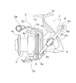
本発明の一実施形態を採用したスピニングリールは、図1及び図2に示すように、ハンドル組立体1と、ハンドル組立体1を回転自在に支持するリール本体2と、ロータ3と、スプール4とを備えている。ロータ3は、スプール4に釣り糸を巻き付けるものであり、リール本体2の前部に回転自在に支持されている。スプール4は、外周面に釣り糸を巻き取るものであり、ロータ3の前部に前後移動自在に配置されている。なお、ハンドル組立体1は、リール本体2の左側(図1及び図2参照)及び右側(図示せず)のいずれにも装着可能であり、ハンドル組立体1が装着されていない側には、キャップ部材19が装着されている。
As shown in FIGS. 1 and 2, a spinning reel employing an embodiment of the present invention includes a
ハンドル組立体1は、ダブルハンドル型とシングルハンドル型との2つのタイプのハンドル組立体に交換可能なものである。ハンドル組立体は、図1に示すように、ハンドル把手6と、ハンドル軸7と、第1ハンドルアーム8a及び第2ハンドルアーム8bと、アーム取付部9と、を備えている。この場合はダブルハンドル型になる。また、ハンドル組立体1は、図5に示すように、シングルハンドル型にした場合の回転バランスを向上させるための重り部材13をさらに備えている。
The
ハンドル把手6は、指のつま先で摘んで操作するタイプのものである。第1ハンドルアーム8a及び第2ハンドルアーム8bの先端にはハンドル把手6が回転自在にそれぞれ装着されている。第1ハンドルアーム8a及び第2ハンドルアーム8bの先端には、ハンドル把手6が回転自在に装着される把手軸6aが固定されている。
The
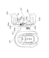
ハンドル軸7は、例えばステンレス合金製の棒状部材である。図3に示すように、ハンドル軸7は、外形が矩形等の非円形に形成されており、後述するマスターギア軸10の非円形の貫通孔10aに一体回転可能かつ軸方向移動可能に装着されている。ハンドル軸7の先端面(図3右側端面)には、中心に雌ねじ部7aが形成されている。貫通孔10aに装着したハンドル軸7の雌ねじ部7aにボルト部材18の雄ねじ部18aを螺合させることによって、ハンドル軸7をマスターギア軸10に対して抜け止めしている。また、ハンドル軸7の基端部(図3左側端部)には、アーム取付部9を連結するためのカシメピン20が貫通するピン貫通孔7bが形成されている。このカシメピン20により、アーム取付部9がハンドル軸7に揺動自在かつ一体回転可能に連結されている。
The handle shaft 7 is a rod-shaped member made of, for example, stainless steel. As shown in FIG. 3, the handle shaft 7 is formed in a non-circular shape such as a rectangle, and is attached to a non-circular through
図1に示すように、第1ハンドルアーム8aと第2ハンドルアーム8bとは同じ形状である。第1ハンドルアーム8aは、ハンドル軸7の軸芯X1と交差する第1軸X2方向に沿って配置されている。第2ハンドルアーム8bは、第1軸X2と軸芯X1を挟んで逆側に配置された第2軸X3方向に沿って配置されている。ここで、第1軸X2及び第2軸X3は、ハンドル軸7の軸芯X1に対して線対称に配置されている。また、第1軸X2及び第2軸X3は、ハンドル軸7と直交する方向よりハンドル軸7の軸方向外方(図3左方)に傾いている。以降の説明では、第1ハンドルアーム8aについて説明し、第2ハンドルアーム8bについては第1ハンドルアーム8aと同じ構成のため説明を省略する。
As shown in FIG. 1, the
第1ハンドルアーム8aは、例えば、アルミニウム合金等の金属製の棒状部材である。第1ハンドルアーム8aは、図1、図2及び図3に示すように、基端に形成されアーム取付部9に装着される非円形軸部8cと、先端部に形成されハンドル把手6の把手軸6aが固定される把手支持部8dと、を有している。第1ハンドルアーム8aの中間部8eは先細りの円柱形状に形成されている。
The
非円形軸部8cの断面は、図4に示すように、中間部8eより小径の円の一部を切り欠いたようなD字形状に形成されている。非円形軸部8cには、図3及び図4に示すように、直径方向(第1軸X2と直交する直径方向)に貫通する2つの雌ネジ孔8fが第1ハンドルアーム8aの長手方向(第1軸X2方向)に間隔を隔てて形成されている。図2に示すように、把手支持部8dには、把手軸6aがカシメ固定されている。非円形軸部8cは、図3に示すように、雌ネジ孔8fに螺合する、例えば皿頭ボルトの形態の2本のネジ部材(第1ネジ部材及び第2ネジ部材の一例)14によりアーム取付部9に固定されている。第1ハンドルアーム8aの中間部8eの非円形軸部8cとの境界部分には、大径部8gが形成されている。この大径部8gと非円形軸部8cとの段差により第1ハンドルアーム8aがアーム取付部9に対して長手方向に位置決めされている。
As shown in FIG. 4, the cross section of the
アーム取付部9は、例えば、亜鉛合金等の金属製又は合成樹脂製の部材である。アーム取付部9は、前述したようにハンドル軸7と一体回転可能である。アーム取付部9は、先端がハンドル軸7に連結される連結部9aと、連結部9aの基端から第1軸X2方向に延びる第1装着部9bと、連結部9aの基端から第2軸X3方向に延びる第2装着部9cと、を有するY字状の部材である。
The
連結部9aは、基端側が僅かに大径の円筒形に形成されている。連結部9aの先端側の中心には、ハンドル軸7が揺動自在に連結される連結凹部9dが形成されている。連結凹部9dは、連結部9aの中心から外周面に欠けてスリット形状に形成されている。また、連結部9aには、連結凹部9dと交差して直径方向に貫通するピン装着孔9eが形成されている。このピン装着孔9eとピン貫通孔7bとを貫通してカシメピン20が装着されている。
The connecting
第1装着部9b及び第2装着部9cは概ね筒状に形成されている。第1装着部9bは、第1ハンドルアーム8a及び第2ハンドルアーム8bのいずれか一方の基端をハンドル軸7の軸芯X1と交差する第1軸X2回りに回転不能かつ着脱自在に装着可能である。第2装着部9cは、第1ハンドルアーム8a及び第2ハンドルアーム8bのいずれか他方の基端を第2軸X3回りに回転不能かつ着脱自在に装着可能である。第1装着部9b及び第2装着部9cの先端部の外周面は、第1ハンドルアーム8aの大径部8gの外周面と面一になるように形成されている。
The first mounting
第1装着部9b及び第2装着部9cは、第1軸X2及び第2軸X3に沿って形成され、非円形軸部8cに係合する非円形凹部9fをそれぞれ有している。非円形凹部9fは、図3に示すように、第1装着部9b及び第2装着部9cの先端面より僅かに奥側から形成されている。また、非円形凹部9fは、図4に示すように、非円形軸部8cに係合するように断面がD字形状に形成されている。第1装着部9b及び第2装着部9cには、ネジ部材14が挿入される2つの挿入孔9gが第1軸X2及び第2軸X3方向に間隔を隔ててそれぞれ形成されている。2つの挿入孔9gは、第1装着部9b及び第2装着部9cのハンドル軸7を装着する方向にある内側部分に、第1軸X2及び第3軸X3と直交する方向に形成されている。したがって、ネジ部材14は、ハンドル軸7を装着する方向から第1装着部9b及び第2装着部9cに挿入され、雌ネジ孔8fにねじ込まれる。ネジ部材14は、第1ハンドルアーム8a及び第2ハンドルアーム8bの抜け止め固定のために設けられている。挿入孔9gは、ネジ部材14の頭部を突出させることなく収納可能なテーパ形状の座繰り面を有している。挿入側の逆側の面には、ネジ部材14の先端部が配置される支持穴9hが形成されている。支持穴9hは、挿入孔9gより小径であり、ネジ部材14のネジ部分の最大径に対して0.1mmから0.5mm程度大きい内径である。これにより、ネジ部材14の先端部が支持される。
The first mounting
重り部材13は、図5に示すように、アーム取付部9の第1装着部9b又は第2装着部9cに装着可能である。重り部材13は、重り部13aと、重り部13aと一体形成された非円形軸部13bと、有している。非円形軸部13bは、第1ハンドルアーム8a及び第2ハンドルアーム8bと同様な形状である。したがって、ネジ部材14により第1装着部9b又は第2装着部9bに固定可能である。重り部13aは、釣り糸が引っ掛かりにくいようにするために、ハンドル軸7の軸方向内方に湾曲して形成されている。
As shown in FIG. 5, the
アーム取付部9とマスターギア軸10との間には、軸つば部材50が配置されている。軸つば部材50は、カラーの機能を果たす部材であり、ハンドル軸7と一体回転可能に連結されている。軸つば部材50は、ハンドル組立体1を装着すると、アーム取付部9の先端面とマスターギア軸10の一方の端面との間に挟持され、それらと一体回転する。
A
このようなハンドル組立体1を折りたたむには、キャップ部材19を外してハンドル軸7にねじ込まれたボルト部材18を緩め、軸つば部材50とアーム取付部9の先端面との間に隙間が生成されるようにする。そして、アーム取付部9をカシメピン20回りにリール本体2側に揺動させることで折りたたみが可能になる。
In order to fold such a
リール本体2は、図1、図2及び図3に示すように、開口を有するリールボディ2aと、開口を塞ぐようにリールボディ2aに着脱自在に装着された蓋部材2bと、蓋部材2bから斜め上前方に延びる竿取付脚2cと、リールボディ2a及び蓋部材2bの後部から下部にわたって装着されるカバー部材2dとを有している。リールボディ2aは内部に空間を有している。この空間内には、ハンドル組立体1の回転に連動してロータ3を回転させるロータ駆動機構5と、スプール4を前後に移動させて釣り糸を均一に巻き取るためのオシレーティング機構16とが設けられている。
As shown in FIGS. 1, 2 and 3, the
ロータ駆動機構5は、図3に示すように、ハンドル組立体1のハンドル軸7が回転不能に装着されたマスターギア軸10とともに回転するマスターギア11と、このマスターギア11に噛み合うピニオンギア12とを有している。マスターギア軸10は、図3に示すように、マスターギア11と一体又は別体に形成された筒状部材であり、内周部の形状が矩形等の非円形(例えば、矩形断面)に形成された貫通孔10aを有している。マスターギア軸10は、リール本体2の両側方に突出したボス部2e、2fの内周部に装着された軸受17a、17bによって、リール本体2に回転自在に支持されている。マスターギア11は、ピニオンギア12に噛み合うフェースギアである。ピニオンギア12は、筒状に形成され、ロータ3の中心部を貫通している。そして、ピニオンギア12の前部が、ナットによってロータ3に固定されている。また、ピニオンギア12の中間部と後端部とが、それぞれ軸受を介してリール本体2に回転自在に支持されている。
As shown in FIG. 3, the
オシレーティング機構16は、図3に示すように、スプール4に連結されたスプール軸15を前後方向に移動させることで、スプール4を前後移動させるための機構である。オシレーティング機構16は、スプール軸15の斜め下方に平行に配置された螺軸21と、螺軸21に沿って前後方向に移動するスライダ22と、螺軸21の先端に固定された中間ギア23とを有している。スライダ22は、スプール軸15の後端に回転不能に固定されている。中間ギア23は、図示しない減速機構を介してピニオンギア12に噛み合っている。この減速機構によって、オシレーティング機構16の前後移動速度が遅くなり、釣り糸をスプール4に緻密に巻き付けることができる。
As shown in FIG. 3, the
ロータ3は、図1に示すように、ピニオンギア12に一体回転可能に連結された円筒部30と、円筒部30の側方に互いに対向して設けられた第1ロータアーム31及び第2ロータアーム32とを有している。円筒部30と第1ロータアーム31及び第2ロータアーム32とは一体に成形されている。第1ロータアーム31及び第2ロータアーム32の先端には、釣り糸をスプール4に案内するベールアーム34が図1に示す糸巻取姿勢とそれから90度程度反転した糸開放姿勢とに揺動自在に装着されている。
As shown in FIG. 1, the
スプール4は、図1に示すように、ロータ3の第1ロータアーム31と第2ロータアーム32との間に配置されている。スプール4は、釣り糸が巻き付けられる糸巻胴部4aと、ロータ3の円筒部30の外周側に配置されるスカート部4bと、糸巻胴部4aの前方に配置された前フランジ部4cと、有している。スプール4は図示しないドラグ機構を介してスプール軸15に連結されている。
As shown in FIG. 1, the
次に、リールの操作及び動作について説明する。 Next, the operation and operation of the reel will be described.
釣りを行う際、キャスティングしてリール本体2から釣り糸を繰り出すために、ベールアーム34を指先で糸巻取姿勢から糸開放姿勢に反転させる。この状態で、釣り竿を握る手の人差し指で釣り糸を引っかけながら釣竿をキャスティングする。すると、釣り糸は仕掛けの重さによって勢いよく前方に放出される。そして、ハンドル組立体1を糸巻取方向に回転させると、ロータ駆動機構5によりロータ3が糸巻取方向に回転し、ベールアーム34が図示しないベール反転機構により糸巻取姿勢に復帰し、釣り糸がスプール4に巻き付けられる。
When fishing, in order to cast the fishing line from the
この釣りを行うとき、たとえば、手返しを頻繁に行う釣りを場合は、ダブルハンドル型にし、釣り糸が糸ふけしやすい釣りを行う場合、シングルハンドル型にする。ダブルハンドル型からシングルハンドル型にする場合、ネジ部材14を外して、第1ハンドルアーム8a又は第2ハンドルアーム8bをアーム取付部9から外し、外した部分に重り部材13を取り付ける。
When this fishing is performed, for example, a double handle type is used for frequent fishing, and a single handle type is used for fishing where the fishing line is likely to dander. When changing from the double handle type to the single handle type, the
このような構成のハンドル組立体1では、アーム取付部9から一方のハンドルアーム(例えば、第2ハンドルアーム8b)を取り外すだけで、シングルハンドル型のリールとして使用できる。
The
また、アーム取付部9を介して第1ハンドルアーム8a又は第2ハンドルアーム8bのトルクがハンドル軸7に伝達される。このため、ダブルハンドル型としての使用時と、シングルハンドル型としての使用時と、で強度が変化することがない。
Further, the torque of the
さらに、第1ハンドルアーム8a及び第2ハンドルアーム8bとアーム固定部9が非円形係合により回り止めされている。したがって、ネジ部材14は、第1ハンドルアーム8a又は第2ハンドルアーム8bを抜け止め固定するだけでよい。このため、巻き上げ時に第1ハンドルアーム8a又は第2ハンドルアーム8bに作用する曲げやねじりの力がネジ部材14に作用せず、比較的小径のネジ部材14であっても破断するおそれがない。
Further, the
<特徴>
(A)ハンドル組立体1は、釣り用リールのハンドル軸7と一体回転可能な組立体である。ハンドル組立体1は、ハンドル把手6と、第1ハンドルアーム8a及び第2ハンドルアーム8bと、アーム取付部9と、を備えている。第1ハンドルアーム8a及び第2ハンドルアーム8bは、ハンドル把手6が先端に回転自在にそれぞれ装着されたものである。アーム取付部9は、ハンドル軸7と一体回転可能である。アーム取付部9は、第1ハンドルアーム8a及び第2ハンドルアーム8bのいずれか一方の基端をハンドル軸7の軸芯X1と交差する第1軸X2回りに回転不能かつ着脱自在に装着可能な第1装着部9bを有している。また、アーム取付部9は、第1ハンドルアーム8a及び第2ハンドルアーム8bのいずれか他方の基端を第1軸X2とハンドル軸7を挟んで配置された第2軸X3回りに回転不能かつ着脱自在に装着可能な第2装着部9cを有している。
<Features>
(A) The
このハンドル組立体1では、ダブルハンドル型にする場合は、第1ハンドルアーム8a及び第2ハンドルアーム8bを第1装着部9b及び第2装着部9cに各別に装着する。また、シングルハンドル型にする場合は、第1ハンドルアーム8a及び第2ハンドルアーム8bのいずれか一方を第1装着部9b及び第2装着部9cのいずれか一方に装着する。ここでは、アーム取付部9の第1装着部9b及び第2装着部9cをハンドル軸7と交差する第1軸X2回り及び第2軸X3回りに回転不能かつ着脱自在に第1ハンドルアーム8a及び第2ハンドルアーム8bを装着可能に構成している。このため、第1ハンドルアーム8a及び第2ハンドルアーム8bの第1軸X2回り及び第2軸X3回りの位置をハンドル把手6がハンドル軸と平行になるように揃えることができる。
In the
(B)第1装着部9b及び第2装着部9cは、第1軸X2及び第2軸X3方向に沿って形成された非円形凹部9fをそれぞれ有し、第1ハンドルアーム8a及び第2ハンドルアーム8bは、非円形凹部9fに係合する非円形軸部8cを基端にそれぞれ有する。この場合には、非円形凹部9fと非円形軸部8cとの係合により第1軸X2回り及び第2軸X3回りに第1ハンドルアーム8a及び第2ハンドルアーム8bを、第1装着部9b及び第2装着部9cにそれぞれ回転不能に装着できる。このため、軸と孔との係合により簡素な構成で第1ハンドルアーム8a及び第2ハンドルアーム8bを第1装着部9b及び第2装着部9cに装着できる。
(B) The first mounting
(C)基端に非円形軸部13bを有し、第1装着部9b及び第2装着部9cの少なくともいずれかに回転不能かつ着脱自在に装着可能な重り部材13をさらに備える。この場合には、シングルハンドル型にする場合、第1ハンドルアーム8aが装着されない第2装着部9cに重り部材13を装着できるので、シングルハンドル型であっても回転バランスが向上する。
(C) A
(D)第1装着部9b及び第2装着部9cに第1軸X2及び第2軸X3と交差しかつハンドル軸7を装着する方向から挿入され、第1ハンドルアーム8a及び第2ハンドルアーム8bの基端部に各別に螺合するネジ部材14をさらに備える。この場合に、ネジ部材14により第1ハンドルアーム8aと第2ハンドルアーム8bとが第1装着部9b及び第2装着部9cにそれぞれ固定されるので、第1ハンドルアーム8a及び第2ハンドルアーム8bを容易に着脱できる。
(D) Inserted into the first mounting
(E)釣り用リールは、スピニングリールであり、ハンドル組立体1は、アーム取付部9と一体回転可能なハンドル軸7をさらに備え、ハンドル軸7は、一端部がマスターギア軸10に一体回転可能に連結され、アーム取付部9は、ハンドル軸7の他端部に装着されている。この場合には、スピニングリールのハンドル組立体において、ダブルハンドル型の場合に、ハンドル把手の方向を揃えることができる。
(E) The fishing reel is a spinning reel, and the
(F)第1軸X2及び第2軸X3は、ハンドル軸7の軸芯X1に対して対称に配置され、かつハンドル軸7と直交する方向よりハンドル軸7の軸方向外方に傾いている。この場合には、第1ハンドルアーム8a及び第2ハンドルアーム8bの先端が基端よりハンドル軸方向外方に離反して配置されるので、第1ハンドルアーム8a及び第2ハンドルアーム8bをスピニングリールのロータ3の釣り糸案内部材であるベールアーム34から離反さして配置できる。
(F) The first axis X2 and the second axis X3 are arranged symmetrically with respect to the axis X1 of the handle shaft 7 and are inclined outward in the axial direction of the handle shaft 7 from the direction perpendicular to the handle shaft 7. . In this case, since the distal ends of the
<他の実施形態>
以上、本発明の一実施形態について説明したが、本発明は上記実施形態に限定されるものではなく、発明の要旨を逸脱しない範囲で種々の変更が可能である。
<Other embodiments>
As mentioned above, although one Embodiment of this invention was described, this invention is not limited to the said embodiment, A various change is possible in the range which does not deviate from the summary of invention.
(a)前記実施形態では、シングルハンドル形の場合にハンドル把手6が指先で摘むタイプのものを使用したが、本発明はこれに限定されない。
(A) In the above-described embodiment, the
図6において、第3ハンドルアーム108cは、ハンドル把手106が手で握る概ねT字形のものになっている。このような第3ハンドル把手106をハンドル組立体101がさらに備えても良い。また、第1ハンドルアーム8a又は第2ハンドルアーム8bに代えて第3ハンドルアーム108cを備えても良い。
In FIG. 6, the third handle arm 108 c has a generally T shape that the
(b)前記実施形態では、釣り用リールとしてスピニングリールを例に本発明のハンドル組立体1を説明したが、本発明はこれに限定されない。
(B) In the above embodiment, the
図7において、ハンドル組立体201は、両軸受リールのハンドル軸207に一体回転可能に装着されたアーム取付部209と、第1ハンドルアーム208a及び第2ハンドルアーム208bと、ハンドル把手206と、を備えている。
In FIG. 7, the
ハンドル把手206は、第1ハンドルアーム208a及び第2ハンドルアーム208bの先端に固定された把手軸206aを有している。第1ハンドルアーム208a及び第2ハンドルアーム208bは、同じ形状であり板状部材である。第1ハンドルアーム208a及び第2ハンドルアーム208bは、アーム取付部209にネジ部材214により、回転不能かつ着脱自在に固定されている。この装着部分は板厚が僅かに薄くなっている。
The
アーム取付部209は、ナット部材212によりハンドル軸207に一体回転可能に固定されている。ハンドル軸207は、リール本体202に回転自在に支持され、その回転がスプール204に伝達される。
The
アーム取付部209は、第1装着部209bと第2装着部209cとを備えている。なお、非円形軸部208c及び非円形凹部209fは共に矩形の断面である。なお、この実施形態では、第1軸X2と第2軸X3は、ハンドル軸207の軸芯X1と直交している。
The
このように本発明に係るハンドル組立体は両軸受リールにも適用できる。 Thus, the handle assembly according to the present invention can also be applied to a dual-bearing reel.
(c)前記実施形態では、非円形係合により第1ハンドルアーム及び第2ハンドルアームをアーム取付部に対して回り止めしたが、回り止め構造は非円形係合に限定されない。 (C) In the above embodiment, the first handle arm and the second handle arm are prevented from rotating with respect to the arm mounting portion by non-circular engagement, but the anti-rotation structure is not limited to non-circular engagement.
6 ハンドル把手
7 ハンドル軸
8a 第1ハンドルアーム
8b 第2ハンドルアーム
8c 非円形軸部
9 アーム取付部
9b 第1装着部
9c 第2装着部
9f 非円形凹部
10 マスターギア軸
13 重り部材
13b 非円形軸部
14 ネジ部材
101 ハンドル組立体
106 ハンドル把手
201 ハンドル組立体
206 ハンドル把手
207 ハンドル軸
208a 第1ハンドルアーム
208b 第2ハンドルアーム
208c 非円形軸部
209 アーム取付部
209b 第1装着部
209c 第2装着部
209f 非円形凹部
212 ナット部材
214 ネジ部材
6 Handle handle 7
Claims (6)
ハンドル把手と、
前記ハンドル把手が回転自在に先端に装着された第1ハンドルアーム及び第2ハンドルアームと、
前記第1ハンドルアーム及び第2ハンドルアームの一方の基端を前記ハンドル軸と交差する第1軸回りに回転不能かつ着脱自在に装着可能な第1装着部、並びに前記第1ハンドルアーム及び第2ハンドルアームの他方の基端を前記ハンドル軸を挟んで前記第1軸と逆側に配置された第2軸回りに回転不能かつ着脱自在に装着可能な前記第2装着部を有し、前記ハンドル軸と一体回転可能なアーム取付部と、
を備えた釣り用リールのハンドル組立体。 A fishing reel handle assembly rotatable integrally with a fishing reel handle shaft,
A handle handle,
A first handle arm and a second handle arm on which the handle handle is rotatably mounted at the tip;
A first mounting portion that is non-rotatable and detachably mountable about a first axis that intersects the handle shaft with one base end of the first handle arm and the second handle arm, and the first handle arm and the second handle arm The second base of the handle arm has a second mounting portion that is non-rotatable and detachably mountable around a second shaft disposed on the opposite side of the first shaft across the handle shaft, and the handle An arm mounting portion that can rotate integrally with the shaft;
A fishing reel handle assembly comprising:
前記第1ハンドルアーム及び前記第2ハンドルアームは、前記非円形凹部に係合する非円形軸部を前記基端にそれぞれ有する、請求項1に記載の釣り用リールのハンドル組立体。 The first mounting part and the second mounting part have a non-circular recess formed along the first axis and the second axis direction,
2. The fishing reel handle assembly according to claim 1, wherein each of the first handle arm and the second handle arm has a non-circular shaft portion that engages with the non-circular recess at the base end.
前記アーム取付部と一体回転可能な前記ハンドル軸をさらに備え、
前記ハンドル軸は、一端部がマスターギア軸に一体回転可能に連結され、
前記アーム取付部は、前記ハンドル軸の他端部に装着されている、請求項1から4のいずれか1項に記載の釣り用リールのハンドル組立体。 The fishing reel is a spinning reel;
The handle shaft further rotatable integrally with the arm mounting portion,
One end of the handle shaft is connected to the master gear shaft so as to be integrally rotatable,
5. The fishing reel handle assembly according to claim 1, wherein the arm mounting portion is attached to the other end portion of the handle shaft. 6.
The first axis and the second axis are arranged symmetrically with respect to the handle axis, and are inclined outward in the axial direction of the handle axis from a direction orthogonal to the handle axis. Fishing reel handle assembly.
Priority Applications (8)
| Application Number | Priority Date | Filing Date | Title |
|---|---|---|---|
| JP2009130738A JP2010273629A (en) | 2009-05-29 | 2009-05-29 | Handle assembly of fishing reel |
| US12/761,060 US8011610B2 (en) | 2009-05-29 | 2010-04-15 | Fishing reel handle assembly |
| SG201002891-8A SG166732A1 (en) | 2009-05-29 | 2010-04-23 | Fishing reel handle assembly |
| MYPI2010001920A MY147298A (en) | 2009-05-29 | 2010-04-29 | Fishing reel handle assembly |
| KR1020100046950A KR20100129165A (en) | 2009-05-29 | 2010-05-19 | Fishing reel handle assembly |
| TW099116145A TW201106858A (en) | 2009-05-29 | 2010-05-20 | Fishing reel handle assembly |
| EP10163430.1A EP2272334B1 (en) | 2009-05-29 | 2010-05-20 | Fishing reel handle assembly |
| CN2010101885930A CN101897325A (en) | 2009-05-29 | 2010-05-28 | Fishing reel handle assembly |
Applications Claiming Priority (1)
| Application Number | Priority Date | Filing Date | Title |
|---|---|---|---|
| JP2009130738A JP2010273629A (en) | 2009-05-29 | 2009-05-29 | Handle assembly of fishing reel |
Publications (2)
| Publication Number | Publication Date |
|---|---|
| JP2010273629A true JP2010273629A (en) | 2010-12-09 |
| JP2010273629A5 JP2010273629A5 (en) | 2012-06-28 |
Family
ID=43219132
Family Applications (1)
| Application Number | Title | Priority Date | Filing Date |
|---|---|---|---|
| JP2009130738A Pending JP2010273629A (en) | 2009-05-29 | 2009-05-29 | Handle assembly of fishing reel |
Country Status (8)
| Country | Link |
|---|---|
| US (1) | US8011610B2 (en) |
| EP (1) | EP2272334B1 (en) |
| JP (1) | JP2010273629A (en) |
| KR (1) | KR20100129165A (en) |
| CN (1) | CN101897325A (en) |
| MY (1) | MY147298A (en) |
| SG (1) | SG166732A1 (en) |
| TW (1) | TW201106858A (en) |
Cited By (3)
| Publication number | Priority date | Publication date | Assignee | Title |
|---|---|---|---|---|
| JP2014023432A (en) * | 2012-07-24 | 2014-02-06 | Shimano Inc | Handle assembly of spinning reel |
| EP3216344A1 (en) | 2016-03-10 | 2017-09-13 | Shimano Inc. | Spinning reel |
| JP2018130040A (en) * | 2017-02-14 | 2018-08-23 | グローブライド株式会社 | Handle of spinning reel for fishing and spinning reel for fishing |
Families Citing this family (9)
| Publication number | Priority date | Publication date | Assignee | Title |
|---|---|---|---|---|
| JP5961364B2 (en) * | 2011-11-18 | 2016-08-02 | 株式会社シマノ | Double-bearing reel handle assembly and dual-bearing reel |
| WO2013180026A1 (en) * | 2012-05-29 | 2013-12-05 | グローブライド株式会社 | Spinning fishing reel |
| JP6046385B2 (en) * | 2012-06-18 | 2016-12-14 | 株式会社シマノ | Electric reel level winding mechanism |
| CN103004713B (en) * | 2012-11-30 | 2014-05-07 | 宁波海宝渔具有限公司 | Gear-driven gapless fishing line reel for fishing |
| JP6227891B2 (en) * | 2013-04-30 | 2017-11-08 | 株式会社シマノ | Fishing reel |
| JP2015047108A (en) * | 2013-08-30 | 2015-03-16 | グローブライド株式会社 | Knob of fishing reel and assembling method |
| JP6688678B2 (en) * | 2016-05-18 | 2020-04-28 | 株式会社シマノ | Spinning reel rotation transmission mechanism |
| JP6949661B2 (en) * | 2017-10-25 | 2021-10-13 | 株式会社シマノ | Handle assembly for spinning reels and spinning reels |
| JP7105613B2 (en) * | 2018-05-22 | 2022-07-25 | 株式会社シマノ | Handle return position adjustment mechanism for fishing reel |
Citations (3)
| Publication number | Priority date | Publication date | Assignee | Title |
|---|---|---|---|---|
| JPS5072690U (en) * | 1973-11-07 | 1975-06-26 | ||
| JP2006042789A (en) * | 2004-07-01 | 2006-02-16 | Daiwa Seiko Inc | Fishing reel |
| JP2007000022A (en) * | 2005-06-21 | 2007-01-11 | Daiwa Seiko Inc | Fishing reel |
Family Cites Families (18)
| Publication number | Priority date | Publication date | Assignee | Title |
|---|---|---|---|---|
| US847890A (en) * | 1905-10-16 | 1907-03-19 | George Washington Blackburn | Fishing-reel. |
| US2691309A (en) * | 1953-08-14 | 1954-10-12 | Horace G Caroland | Casting reel handle |
| US3089663A (en) * | 1962-05-07 | 1963-05-14 | Sr Dean E Kirby | Combination spinning and fly reel |
| US3375993A (en) * | 1966-02-15 | 1968-04-02 | Maurice S. Hayes | Adjustable crank mechanism for fishing reels |
| US3727857A (en) * | 1971-09-28 | 1973-04-17 | G Chann | Convertible fishing reel |
| FR2637458B1 (en) * | 1988-10-07 | 1991-01-04 | Mitchell Sports | FISHING REEL HANDLE |
| JP2536093Y2 (en) * | 1990-04-18 | 1997-05-21 | ダイワ精工株式会社 | Fishing reel |
| US6112617A (en) * | 1997-06-26 | 2000-09-05 | Abrams; David Bartlett | Composite winch handles |
| JP3494863B2 (en) * | 1997-09-30 | 2004-02-09 | ダイワ精工株式会社 | Fishing reel |
| US6364229B1 (en) * | 2000-02-23 | 2002-04-02 | Brunswick Corporation | Fishing reel crank handle with dynamic balancing structure |
| JP2002360136A (en) | 2001-06-04 | 2002-12-17 | Shimano Inc | Handle assembly for double bearing reel |
| US6666396B2 (en) * | 2001-06-11 | 2003-12-23 | Gator Grip, Inc. | Multidirectional rotatable handle |
| US6648257B2 (en) * | 2002-01-28 | 2003-11-18 | Han-Chi Lu | Extendible crank of fishing reel |
| JP2006204141A (en) * | 2005-01-26 | 2006-08-10 | Daiwa Seiko Inc | Handle of fishing reel |
| JP4471294B2 (en) * | 2005-06-27 | 2010-06-02 | グローブライド株式会社 | Fishing reel |
| JP2009065933A (en) * | 2007-09-14 | 2009-04-02 | Shimano Inc | Spinning reel |
| US20090283619A1 (en) * | 2008-05-19 | 2009-11-19 | Young John N | Grip design for fishing reels |
| JP5292152B2 (en) * | 2009-03-26 | 2013-09-18 | 株式会社シマノ | Fishing reel handle arm mounting structure |
-
2009
- 2009-05-29 JP JP2009130738A patent/JP2010273629A/en active Pending
-
2010
- 2010-04-15 US US12/761,060 patent/US8011610B2/en not_active Expired - Fee Related
- 2010-04-23 SG SG201002891-8A patent/SG166732A1/en unknown
- 2010-04-29 MY MYPI2010001920A patent/MY147298A/en unknown
- 2010-05-19 KR KR1020100046950A patent/KR20100129165A/en not_active Application Discontinuation
- 2010-05-20 EP EP10163430.1A patent/EP2272334B1/en not_active Not-in-force
- 2010-05-20 TW TW099116145A patent/TW201106858A/en unknown
- 2010-05-28 CN CN2010101885930A patent/CN101897325A/en active Pending
Patent Citations (3)
| Publication number | Priority date | Publication date | Assignee | Title |
|---|---|---|---|---|
| JPS5072690U (en) * | 1973-11-07 | 1975-06-26 | ||
| JP2006042789A (en) * | 2004-07-01 | 2006-02-16 | Daiwa Seiko Inc | Fishing reel |
| JP2007000022A (en) * | 2005-06-21 | 2007-01-11 | Daiwa Seiko Inc | Fishing reel |
Cited By (4)
| Publication number | Priority date | Publication date | Assignee | Title |
|---|---|---|---|---|
| JP2014023432A (en) * | 2012-07-24 | 2014-02-06 | Shimano Inc | Handle assembly of spinning reel |
| EP3216344A1 (en) | 2016-03-10 | 2017-09-13 | Shimano Inc. | Spinning reel |
| US10334833B2 (en) | 2016-03-10 | 2019-07-02 | Shimano Inc. | Spinning reel |
| JP2018130040A (en) * | 2017-02-14 | 2018-08-23 | グローブライド株式会社 | Handle of spinning reel for fishing and spinning reel for fishing |
Also Published As
| Publication number | Publication date |
|---|---|
| SG166732A1 (en) | 2010-12-29 |
| TW201106858A (en) | 2011-03-01 |
| EP2272334A3 (en) | 2013-03-27 |
| US8011610B2 (en) | 2011-09-06 |
| MY147298A (en) | 2012-11-30 |
| US20100301150A1 (en) | 2010-12-02 |
| EP2272334B1 (en) | 2014-12-24 |
| EP2272334A2 (en) | 2011-01-12 |
| CN101897325A (en) | 2010-12-01 |
| KR20100129165A (en) | 2010-12-08 |
Similar Documents
| Publication | Publication Date | Title |
|---|---|---|
| JP2010273629A (en) | Handle assembly of fishing reel | |
| JP2010273629A5 (en) | ||
| US7137585B2 (en) | Fishing line guide mechanism for a spinning reel | |
| JP4045167B2 (en) | Spinning reel handle assembly | |
| KR101396775B1 (en) | Spinning reel handle assembly | |
| KR101736785B1 (en) | Spinning reel fishing line guide mechanism | |
| KR101806336B1 (en) | Master gear assembly | |
| US20040144877A1 (en) | Level wind mechanism for a dual bearing reel | |
| KR100994411B1 (en) | Handle assembly for a spinning reel | |
| KR100656501B1 (en) | Device for guiding fishline of spinning reel | |
| KR20040019947A (en) | Spinning-reel fishing-line guiding mechanism | |
| US7007880B2 (en) | Fishing line guide mechanism for spinning reel | |
| JP3905068B2 (en) | Spinning reel rotor | |
| US7077349B2 (en) | Fishing line guide mechanism for spinning reel | |
| JP3934260B2 (en) | Bale support member mounting structure for spinning reel | |
| JP3526201B2 (en) | Spinning reel rotor | |
| JP7384851B2 (en) | spinning reel for fishing | |
| JP3993811B2 (en) | Spinning reel handle assembly | |
| JP2001269094A (en) | Spool of spinning reel | |
| JP3825379B2 (en) | Fishing reel guide mechanism for spinning reel | |
| JP4128303B2 (en) | Spinning reel spool and spooling aid | |
| JP2005087007A (en) | Handle-attaching structure of reel for fishing | |
| JP2001258436A (en) | Line-guiding mechanism of spinning reel | |
| JPH10210898A (en) | Spinning reel for fishing | |
| JP2002335823A (en) | Fastening structure of fishing component |
Legal Events
| Date | Code | Title | Description |
|---|---|---|---|
| A521 | Written amendment |
Free format text: JAPANESE INTERMEDIATE CODE: A523 Effective date: 20120419 |
|
| A621 | Written request for application examination |
Free format text: JAPANESE INTERMEDIATE CODE: A621 Effective date: 20120419 |
|
| A521 | Written amendment |
Free format text: JAPANESE INTERMEDIATE CODE: A523 Effective date: 20120514 |
|
| A977 | Report on retrieval |
Free format text: JAPANESE INTERMEDIATE CODE: A971007 Effective date: 20130710 |
|
| A131 | Notification of reasons for refusal |
Free format text: JAPANESE INTERMEDIATE CODE: A131 Effective date: 20130723 |
|
| A521 | Written amendment |
Free format text: JAPANESE INTERMEDIATE CODE: A523 Effective date: 20131010 |
|
| A02 | Decision of refusal |
Free format text: JAPANESE INTERMEDIATE CODE: A02 Effective date: 20140128 |