JP6686824B2 - Pedal device - Google Patents
Pedal device Download PDFInfo
- Publication number
- JP6686824B2 JP6686824B2 JP2016189181A JP2016189181A JP6686824B2 JP 6686824 B2 JP6686824 B2 JP 6686824B2 JP 2016189181 A JP2016189181 A JP 2016189181A JP 2016189181 A JP2016189181 A JP 2016189181A JP 6686824 B2 JP6686824 B2 JP 6686824B2
- Authority
- JP
- Japan
- Prior art keywords
- pedal
- pedal pad
- pad
- displacement amount
- accelerator device
- Prior art date
- Legal status (The legal status is an assumption and is not a legal conclusion. Google has not performed a legal analysis and makes no representation as to the accuracy of the status listed.)
- Active
Links
- 238000006073 displacement reaction Methods 0.000 claims description 81
- 238000004364 calculation method Methods 0.000 claims description 39
- 238000001514 detection method Methods 0.000 claims description 16
- 230000008602 contraction Effects 0.000 claims 1
- 230000000694 effects Effects 0.000 description 58
- 238000010586 diagram Methods 0.000 description 25
- JOYRKODLDBILNP-UHFFFAOYSA-N Ethyl urethane Chemical compound CCOC(N)=O JOYRKODLDBILNP-UHFFFAOYSA-N 0.000 description 11
- 230000000881 depressing effect Effects 0.000 description 6
- 125000006850 spacer group Chemical group 0.000 description 4
- 125000002066 L-histidyl group Chemical group [H]N1C([H])=NC(C([H])([H])[C@](C(=O)[*])([H])N([H])[H])=C1[H] 0.000 description 2
- 230000000994 depressogenic effect Effects 0.000 description 2
- 230000037237 body shape Effects 0.000 description 1
Images


Classifications
-
- B—PERFORMING OPERATIONS; TRANSPORTING
- B60—VEHICLES IN GENERAL
- B60T—VEHICLE BRAKE CONTROL SYSTEMS OR PARTS THEREOF; BRAKE CONTROL SYSTEMS OR PARTS THEREOF, IN GENERAL; ARRANGEMENT OF BRAKING ELEMENTS ON VEHICLES IN GENERAL; PORTABLE DEVICES FOR PREVENTING UNWANTED MOVEMENT OF VEHICLES; VEHICLE MODIFICATIONS TO FACILITATE COOLING OF BRAKES
- B60T7/00—Brake-action initiating means
- B60T7/02—Brake-action initiating means for personal initiation
- B60T7/04—Brake-action initiating means for personal initiation foot actuated
- B60T7/042—Brake-action initiating means for personal initiation foot actuated by electrical means, e.g. using travel or force sensors
-
- G—PHYSICS
- G05—CONTROLLING; REGULATING
- G05G—CONTROL DEVICES OR SYSTEMS INSOFAR AS CHARACTERISED BY MECHANICAL FEATURES ONLY
- G05G1/00—Controlling members, e.g. knobs or handles; Assemblies or arrangements thereof; Indicating position of controlling members
- G05G1/30—Controlling members actuated by foot
-
- B—PERFORMING OPERATIONS; TRANSPORTING
- B60—VEHICLES IN GENERAL
- B60K—ARRANGEMENT OR MOUNTING OF PROPULSION UNITS OR OF TRANSMISSIONS IN VEHICLES; ARRANGEMENT OR MOUNTING OF PLURAL DIVERSE PRIME-MOVERS IN VEHICLES; AUXILIARY DRIVES FOR VEHICLES; INSTRUMENTATION OR DASHBOARDS FOR VEHICLES; ARRANGEMENTS IN CONNECTION WITH COOLING, AIR INTAKE, GAS EXHAUST OR FUEL SUPPLY OF PROPULSION UNITS IN VEHICLES
- B60K26/00—Arrangements or mounting of propulsion unit control devices in vehicles
- B60K26/02—Arrangements or mounting of propulsion unit control devices in vehicles of initiating means or elements
-
- B—PERFORMING OPERATIONS; TRANSPORTING
- B60—VEHICLES IN GENERAL
- B60T—VEHICLE BRAKE CONTROL SYSTEMS OR PARTS THEREOF; BRAKE CONTROL SYSTEMS OR PARTS THEREOF, IN GENERAL; ARRANGEMENT OF BRAKING ELEMENTS ON VEHICLES IN GENERAL; PORTABLE DEVICES FOR PREVENTING UNWANTED MOVEMENT OF VEHICLES; VEHICLE MODIFICATIONS TO FACILITATE COOLING OF BRAKES
- B60T7/00—Brake-action initiating means
- B60T7/02—Brake-action initiating means for personal initiation
- B60T7/04—Brake-action initiating means for personal initiation foot actuated
- B60T7/06—Disposition of pedal
-
- G—PHYSICS
- G01—MEASURING; TESTING
- G01L—MEASURING FORCE, STRESS, TORQUE, WORK, MECHANICAL POWER, MECHANICAL EFFICIENCY, OR FLUID PRESSURE
- G01L5/00—Apparatus for, or methods of, measuring force, work, mechanical power, or torque, specially adapted for specific purposes
- G01L5/22—Apparatus for, or methods of, measuring force, work, mechanical power, or torque, specially adapted for specific purposes for measuring the force applied to control members, e.g. control members of vehicles, triggers
- G01L5/225—Apparatus for, or methods of, measuring force, work, mechanical power, or torque, specially adapted for specific purposes for measuring the force applied to control members, e.g. control members of vehicles, triggers to foot actuated controls, e.g. brake pedals
-
- G—PHYSICS
- G05—CONTROLLING; REGULATING
- G05G—CONTROL DEVICES OR SYSTEMS INSOFAR AS CHARACTERISED BY MECHANICAL FEATURES ONLY
- G05G1/00—Controlling members, e.g. knobs or handles; Assemblies or arrangements thereof; Indicating position of controlling members
- G05G1/30—Controlling members actuated by foot
- G05G1/38—Controlling members actuated by foot comprising means to continuously detect pedal position
-
- G—PHYSICS
- G05—CONTROLLING; REGULATING
- G05G—CONTROL DEVICES OR SYSTEMS INSOFAR AS CHARACTERISED BY MECHANICAL FEATURES ONLY
- G05G1/00—Controlling members, e.g. knobs or handles; Assemblies or arrangements thereof; Indicating position of controlling members
- G05G1/30—Controlling members actuated by foot
- G05G1/44—Controlling members actuated by foot pivoting
-
- G—PHYSICS
- G05—CONTROLLING; REGULATING
- G05G—CONTROL DEVICES OR SYSTEMS INSOFAR AS CHARACTERISED BY MECHANICAL FEATURES ONLY
- G05G5/00—Means for preventing, limiting or returning the movements of parts of a control mechanism, e.g. locking controlling member
- G05G5/03—Means for enhancing the operator's awareness of arrival of the controlling member at a command or datum position; Providing feel, e.g. means for creating a counterforce
-
- B—PERFORMING OPERATIONS; TRANSPORTING
- B60—VEHICLES IN GENERAL
- B60K—ARRANGEMENT OR MOUNTING OF PROPULSION UNITS OR OF TRANSMISSIONS IN VEHICLES; ARRANGEMENT OR MOUNTING OF PLURAL DIVERSE PRIME-MOVERS IN VEHICLES; AUXILIARY DRIVES FOR VEHICLES; INSTRUMENTATION OR DASHBOARDS FOR VEHICLES; ARRANGEMENTS IN CONNECTION WITH COOLING, AIR INTAKE, GAS EXHAUST OR FUEL SUPPLY OF PROPULSION UNITS IN VEHICLES
- B60K23/00—Arrangement or mounting of control devices for vehicle transmissions, or parts thereof, not otherwise provided for
- B60K23/02—Arrangement or mounting of control devices for vehicle transmissions, or parts thereof, not otherwise provided for for main transmission clutches
Description
本発明は、ペダル装置に関する。 The present invention relates to a pedal device.
従来、車両に搭載され、車両の運転者がペダルを踏み込む力(以下、「踏力」という)に応じて車両の運転状態を制御するペダル装置が知られている。例えば、特許文献1には、ペダル、当該ペダルの一方の端部を回転可能に支持する支持部、伸縮可能な材料から形成されペダルと車体との間に設けられる伸縮部材、および、当該伸縮部材の変位量を検出する変位量検出部を備えるペダル装置が記載されている。 2. Description of the Related Art Conventionally, there is known a pedal device that is mounted on a vehicle and that controls a driving state of the vehicle in accordance with a force with which a driver of the vehicle depresses a pedal (hereinafter, referred to as “pedal force”). For example, in Patent Document 1, a pedal, a support portion that rotatably supports one end portion of the pedal, a stretchable member that is formed of a stretchable material and is provided between the pedal and the vehicle body, and the stretchable member. There is described a pedal device including a displacement amount detection unit that detects the displacement amount of the.
しかしながら、特許文献1に記載のペダル装置では、ペダルを踏み込んだとき、当該ペダルにマットなどの異物が引っ掛かると、ペダルから足を離しても支持部を中心に回転しなくなるためペダルが元の位置に戻らなくなるおそれがある。このため、伸縮部材は圧縮されたままとなり、伸縮部材の変位量に基づいて算出されるペダルの操作量が意図しない値となる。 However, in the pedal device described in Patent Document 1, when a foreign material such as a mat is caught on the pedal when the pedal is depressed, the pedal does not rotate around the support portion even if the foot is released from the pedal, and thus the pedal is in the original position. May not return to. Therefore, the elastic member remains compressed, and the pedal operation amount calculated based on the displacement amount of the elastic member becomes an unintended value.
本発明の目的は、操作者による操作量を確実に検出可能なペダル装置を提供することにある。 An object of the present invention is to provide a pedal device that can reliably detect the amount of operation by the operator.
本発明は、ペダル装置であって、可撓性のある材料から形成されており、操作者の踏み込みによって当該踏み込みの方向に変形可能なペダルパッドと、ペダルパッドの複数の箇所に設けられ、ペダルパッドの変位量を検出し、当該変位量に応じた信号を出力する同種の複数の変位量検出部と、を備え、変位量検出部は、ペダルパッドの表面または裏面に沿った方向の伸縮を検出し、踏み込みの方向の変位量に換算して出力する歪みゲージであることを特徴とする。 The present invention is a pedal device, which is formed of a flexible material, and is provided at a plurality of locations on a pedal pad that is deformable in the direction of the pedal when the operator depresses the pedal pad. A plurality of displacement amount detection units of the same type that detect a displacement amount of the pad and output a signal according to the displacement amount, and the displacement amount detection unit expands or contracts in a direction along the front surface or the back surface of the pedal pad. detected, and wherein the Oh Rukoto a strain gauge in terms outputted to the displacement of the direction of depression.
本発明のペダル装置では、操作者が踏み込むペダルパッドが踏み込みの方向に変形可能に形成され、ペダルパッドの変位量を変位量検出部が検出可能となっている。これにより、本発明のペダル装置では、操作者が踏み込んでいないときのペダルパッドの状態(以下、「初期状態」という)に対する踏み込まれているときの変位量に基づいて操作者による操作量を導き出すことができる。また、操作者がペダルパッドから足を離すとペダルパッドは初期状態に戻るため、ペダル装置における操作量がマットとの引っ掛かりなど不具合によって操作者が意図しない値となることを防止できる。したがって、本発明のペダル装置は、操作者による操作量を確実に検出することができる。 In the pedal device of the present invention, the pedal pad on which the operator depresses is formed so as to be deformable in the depressing direction, and the displacement amount detection unit can detect the displacement amount of the pedal pad. As a result, in the pedal device of the present invention, the operation amount by the operator is derived based on the displacement amount when the operator is not stepping on the pedal pad state (hereinafter, referred to as “initial state”). be able to. Further, since the pedal pad returns to the initial state when the operator releases his / her foot from the pedal pad, it is possible to prevent the operation amount in the pedal device from becoming a value that the operator does not intend due to a problem such as catching with the mat. Therefore, the pedal device of the present invention can reliably detect the amount of operation by the operator.
以下、本発明の複数の実施形態を図面に基づき説明する。なお、複数の実施形態において実質的に同一の部位には同一の符号を付し、説明を省略する。第二、第四、第二十三実施形態、および、それらの実施形態と他の実施形態とを組み合わせた実施形態が請求項に係る発明を実施するための形態に相当する。 Hereinafter, a plurality of embodiments of the present invention will be described with reference to the drawings. In addition, in a plurality of embodiments, the substantially same parts are designated by the same reference numerals, and description thereof will be omitted. The second, fourth, and twenty-third embodiments, and the embodiments in which those embodiments are combined with other embodiments correspond to the modes for carrying out the claimed invention.
(第一実施形態)
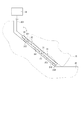
本発明の第一実施形態によるペダル装置を図1に示す。「ペダル装置」としてのアクセル装置1は、図示しない車両用エンジンのスロットルバルブのバルブ開度を決定するため車両の「操作者」としての運転者が操作する入力装置である。アクセル装置1は、電子式であり、ペダルパッド31の「操作量」としての踏み込み量を表す電気信号を図示しない電子制御装置に伝達する。電子制御装置は、当該踏み込み量や他の情報に基づき図示しないスロットルアクチュエータによりスロットルバルブを駆動する。
(First embodiment)
A pedal system according to the first embodiment of the present invention is shown in FIG. The accelerator device 1 as a “pedal device” is an input device operated by a driver as an “operator” of the vehicle to determine the valve opening of a throttle valve of a vehicle engine (not shown). The accelerator device 1 is of an electronic type, and transmits an electric signal representing a depression amount as an “operation amount” of the
アクセル装置1は、ペダルパッド31、「変位量検出部」としての歪みゲージ32、コネクタ33、および、演算部34を有する。アクセル装置1は、アクセル装置1を搭載する車両の図示しない車室において、運転者が足25で踏み込みやすい場所に設けられる。アクセル装置1は、「ベース」としての車体26に支持されている。以下、図1において、車体26の内壁面261に沿って運転者の足25のつま先側を「上側」、および、運転者の足25のかかと側を「下側」と称する。
The accelerator device 1 includes a
ペダルパッド31は、平板状に形成されている部材であって、可撓性のある材料から形成されている。ペダルパッド31は、運転者の足25に当接可能な「操作者の足が当接する側」としての表面311と、表面311とは反対側の「操作者の足が当接する側とは反対側」としての裏面312と、を有する。裏面312には、裏面312と内壁面261との間に隙間310を形成可能なスペーサ313、314が設けられている。ペダルパッド31は、運転者が踏み込むと、「踏み込みの方向」としての白抜き矢印F1の方向に変形可能である(図1の点線で示すペダルパッド31を参照)。
The
歪みゲージ32は、ペダルパッド31の表面311側であって、ペダルパッド31の上側に設けられている。歪みゲージ32は、ペダルパッド31の変位量を検出し、当該変位量に応じた電気信号をコネクタ33に出力する。
The
コネクタ33は、ペダルパッド31の上側に設けられている。コネクタ33は、ケーブル331を介して歪みゲージ32が出力する電気信号を演算部34に出力する。
The
演算部34は、例えば、外部の電子制御装置としてのエンジンコントロールユニットに設けられている。演算部34は、コネクタ33を介して歪みゲージ32から出力された電気信号に基づいて、ペダルパッド31の変位量を算出する。演算部34では、算出された変位量に基づいて運転者の踏み込み量が算出される。算出された当該踏み込み量は、電子制御装置にて外部に出力する信号に変換され、外部の吸気量を調整する電子スロットルに出力される。これにより、電子スロットルの開度が制御される。
The
次に、アクセル装置1の作動について説明する。
アクセル装置1において、運転者がペダルパッド31を踏み込むと、ペダルパッド31は白抜き矢印F1の方向に変形する。歪みゲージ32は、ペダルパッド31の変位量を検出し、コネクタ33を介して当該変位量に応じた電気信号を電子制御装置に伝達する。電子制御装置では、当該電気信号に基づいてスロットルバルブの駆動を制御する。
Next, the operation of the accelerator device 1 will be described.
In accelerator device 1, when the driver steps on
(a)第一実施形態によるアクセル装置1は、運転者が踏み込むと当該踏み込んだ方向に変形するペダルパッド31を備えている。アクセル装置1では、この変位量を歪みゲージ32によって検出し、運転者の踏み込み量を算出する。運転者による踏み込みが解除されると、変形していたペダルパッド31が初期状態に戻る。ペダルパッド31が初期状態に戻ると、歪みゲージ32において検出されるペダルパッド31の変位量が0となるため、演算部34は、運転者の踏み込み量が0であると算出する。これにより、ペダルパッドがシャフトを回転中心として回転するアクセル装置のように、マットなどとの引っ掛かりによって運転者の踏み込み量が意図しない値となることを防止できる。したがって、アクセル装置1は、運転者の踏み込み量を確実に検出することができる。
(A) The accelerator device 1 according to the first embodiment includes the
(第二実施形態)
次に、本発明の第二実施形態によるペダル装置を図2に基づいて説明する。第二実施形態は、歪みゲージの数が第一実施形態と異なる。
(Second embodiment)
Next, a pedal system according to a second embodiment of the present invention will be described with reference to FIG. The second embodiment differs from the first embodiment in the number of strain gauges.
本発明の第二実施形態による「ペダル装置」としてのアクセル装置2を図2に示す。アクセル装置2は、ペダルパッド31、「変位量検出部」としての歪みゲージ37、38、コネクタ33、および、演算部44を有する。
FIG. 2 shows an
歪みゲージ37、38は、ペダルパッド31の表面311側に設けられている。歪みゲージ37は、ペダルパッド31の上側に設けられている。歪みゲージ38は、ペダルパッド31の下側に設けられている。歪みゲージ37、38は、それぞれの配置場所におけるペダルパッド31の変位量を検出し、当該変位量に応じた電気信号をコネクタ33に出力する。すなわち、第二実施形態では、演算部44に向けて二つの電気信号が出力される。
The strain gauges 37 and 38 are provided on the
演算部44は、コネクタ33が出力する二つの電気信号に基づいてペダルパッド31の変位量を算出する。このとき、演算部44では、二つの電気信号に基づいて算出された二つの変位量のうちの最大値をペダルパッド31の変位量とする。演算部44では、算出された二つの変位量の最大値に基づいて運転者の踏み込み量を算出する。算出された当該踏み込み量は、電子制御装置に伝達される。
The
第二実施形態によるアクセル装置2は、第一実施形態の効果(a)を奏する。
(b)第二実施形態によるアクセル装置2では、二つの歪みゲージ37、38がそれぞれ設けられる位置におけるペダルパッド31の変位量のうちの最大値をペダルパッド31の変位量とする。これにより、二つの歪みゲージ37、38のいずれかが変形することによってペダルパッド31の変形を検出することができ、当該変形の大きさによって運転者の踏み込み量を算出することができる。また、運転者の踏力のペダルパッド31へのかかり具合によって一つの歪みゲージでペダルパッド31の変形が検出できない場合でも他の歪みゲージで検出することができる。これらにより、運転者の踏み込み量の検出精度を向上することができる。
The
(B) In the
(第三実施形態)
次に、本発明の第三実施形態によるペダル装置を図3に基づいて説明する。第三実施形態は、歪みゲージが設けられる位置が第一実施形態と異なる。
(Third embodiment)
Next, a pedal system according to a third embodiment of the present invention will be described with reference to FIG. The third embodiment is different from the first embodiment in the position where the strain gauge is provided.
本発明の第三実施形態による「ペダル装置」としてのアクセル装置3を図3に示す。アクセル装置3は、ペダルパッド31、「変位量検出部」としての歪みゲージ42、コネクタ33、および、演算部34を有する。
FIG. 3 shows an accelerator device 3 as a “pedal device” according to a third embodiment of the present invention. The accelerator device 3 includes a
歪みゲージ42は、ペダルパッド31の裏面312側であって、ペダルパッド31の略中央に設けられている。歪みゲージ42は、ペダルパッド31の変位量を検出し、当該変位量に応じた電気信号をコネクタ33に出力する。
The
第三実施形態によるアクセル装置3は、第一実施形態の効果(a)を奏する。
(c)また、第三実施形態によるアクセル装置3では、歪みゲージ42は、ペダルパッド31の裏面312側に設けられるため、運転者の足25と接触することはない。これにより、歪みゲージと足25との接触によって発生するおそれがある変位量の検出誤差を0にすることができる。したがって、運転者の踏み込み量の検出精度をさらに向上することができる。
The accelerator device 3 according to the third embodiment has the effect (a) of the first embodiment.
(C) Further, in the accelerator device 3 according to the third embodiment, since the
(d)また、歪みゲージ42は、運転者の足25と接触しないため、裏面312における位置を自由に選択することができる。これにより、アクセル装置2のように、変位量が最も大きくなるペダルパッド31の略中央に設けることもできる。したがって、運転者の踏み込み量の僅かな違いも検出することができるため、運転者の踏み込み量の検出精度をさらに向上することができる。
(D) Further, since the
(第四実施形態)
次に、本発明の第四実施形態によるペダル装置を図4に基づいて説明する。第四実施形態は、歪みゲージの数が第三実施形態と異なる。
(Fourth embodiment)
Next, a pedal system according to a fourth embodiment of the present invention will be described with reference to FIG. The fourth embodiment is different from the third embodiment in the number of strain gauges.
本発明の第四実施形態による「ペダル装置」としてのアクセル装置4を図4に示す。アクセル装置4は、ペダルパッド31、「変位量検出部」としての歪みゲージ47、48、コネクタ33、および、演算部44を有する。
An accelerator device 4 as a "pedal device" according to the fourth embodiment of the present invention is shown in FIG. The accelerator device 4 includes a
歪みゲージ47、48は、ペダルパッド31の裏面312側に設けられている。歪みゲージ47は、ペダルパッド31の上側に設けられている。歪みゲージ48は、ペダルパッド31の下側に設けられている。歪みゲージ47、48は、それぞれの配置場所におけるペダルパッド31の変位量を検出し、当該変位量に応じた電気信号をコネクタ33に出力する。すなわち、第四実施形態では、演算部44に向けて二つの電気信号が出力される。
The strain gauges 47 and 48 are provided on the
第四実施形態によるアクセル装置4は、第一実施形態の効果(a)、第二実施形態の効果(b)、および、第三実施形態の効果(c)を奏する。
また、歪みゲージ47、48のいずれか一方をペダルパッド31の略中央に設ける場合、第三実施形態の効果(d)も奏する。
The accelerator device 4 according to the fourth embodiment exhibits the effect (a) of the first embodiment, the effect (b) of the second embodiment, and the effect (c) of the third embodiment.
Further, when either one of the strain gauges 47 and 48 is provided at the substantially center of the
(第五実施形態)
次に、本発明の第五実施形態によるペダル装置を図5に基づいて説明する。第五実施形態は、ペダルパッドの形状が第一実施形態と異なる。
(Fifth embodiment)
Next, a pedal system according to a fifth embodiment of the present invention will be described with reference to FIG. The fifth embodiment differs from the first embodiment in the shape of the pedal pad.
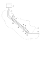
本発明の第五実施形態による「ペダル装置」としてのアクセル装置5を図5に示す。アクセル装置5は、ペダルパッド41、歪みゲージ32、コネクタ33、および、演算部34を有する。
FIG. 5 shows an
ペダルパッド41は、可撓性のある材料から形成されている。ペダルパッド41は、ペダルパッド41が設けられている車体26の内壁面261から離れる方向に突出するよう湾曲した形状をなしている。
ペダルパッド41は、運転者の足25に当接可能な「操作者の足が当接する側」としての表面411と、表面411とは反対側の「操作者の足が当接する側とは反対側」としての裏面412と、を有する。ペダルパッド41の上側の端部および下側の端部には、ペダルパッド41を車体26に対して固定する固定端部413、414が設けられている。ペダルパッド41は、運転者が踏み込むと、「踏み込みの方向」としての白抜き矢印F5の方向に変形可能である。
歪みゲージ32は、ペダルパッド41の表面411側であって、ペダルパッド41の上側に設けられている。
コネクタ33は、ペダルパッド41の上側に設けられている。
The
The
The
The
第五実施形態によるアクセル装置5は、第一実施形態の効果(a)を奏する。
(e)また、第五実施形態によるアクセル装置5では、ペダルパッド41は、車体26の内壁面261から離れる方向に突出するよう形成されているため、裏面412と内壁面261との間の隙間410が第一実施形態における隙間310に比べ大きい。これにより、ペダルパッド41の白抜き矢印F5方向の変位量が大きくなるため、運転者は、踏み込み量を調整しやすくなる。したがって、操作性を向上することができる。
The
(E) Further, in the
(第六実施形態)
次に、本発明の第六実施形態によるペダル装置を図6に基づいて説明する。第六実施形態は、歪みゲージが設けられる位置が第五実施形態と異なる。
(Sixth embodiment)
Next, a pedal system according to a sixth embodiment of the present invention will be described with reference to FIG. The sixth embodiment is different from the fifth embodiment in the position where the strain gauge is provided.
本発明の第六実施形態による「ペダル装置」としてのアクセル装置6を図6に示す。アクセル装置6は、ペダルパッド41、歪みゲージ42、コネクタ33、および、演算部34を有する。
An accelerator device 6 as a "pedal device" according to the sixth embodiment of the present invention is shown in FIG. The accelerator device 6 includes a
歪みゲージ42は、ペダルパッド41の裏面412側であって、ペダルパッド41の略中央に設けられている。歪みゲージ42は、ペダルパッド41の変位量を検出し、当該変位量に応じた電気信号をコネクタ33に出力する。
The
第六実施形態によるアクセル装置6は、第一実施形態の効果(a)、第三実施形態の効果(c)、(d)、および、第五実施形態の効果(e)を奏する。 The accelerator device 6 according to the sixth embodiment exhibits the effect (a) of the first embodiment, the effects (c) and (d) of the third embodiment, and the effect (e) of the fifth embodiment.
(第七実施形態)
次に、本発明の第七実施形態によるペダル装置を図7に基づいて説明する。第七実施形態は、車体に対するペダルパッドの動きが第五実施形態と異なる。
(Seventh embodiment)
Next, a pedal system according to a seventh embodiment of the present invention will be described with reference to FIG. The seventh embodiment is different from the fifth embodiment in the movement of the pedal pad with respect to the vehicle body.
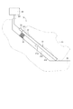
本発明の第七実施形態による「ペダル装置」としてのアクセル装置7を図7に示す。アクセル装置7は、ペダルパッド51、歪みゲージ32、コネクタ33、および、演算部34を有する。
FIG. 7 shows an
ペダルパッド51は、可撓性のある材料から形成されている。ペダルパッド51は、ペダルパッド51が設けられている車体26の内壁面261から離れる方向に突出するよう湾曲した形状をなしている。
ペダルパッド51は、運転者の足25に当接可能な「操作者の足が当接する側」としての表面511と、表面511とは反対側の「操作者の足が当接する側とは反対側」としての裏面512と、を有する。裏面512と内壁面261との間には隙間510が形成されている。ペダルパッド51の上側の端部には、車体26の内壁面261に沿って移動可能な「ペダルパッドの少なくとも二つの端部のいずれか一方」としての自由端部513が設けられている。また、ペダルパッド51の下側の端部には、車体26に固定される固定端部514が設けられている。ペダルパッド51は、運転者が踏み込むと、「踏み込みの方向」としての白抜き矢印F7の方向に変形可能である。
歪みゲージ32は、ペダルパッド51の表面511側であって、ペダルパッド51の上側に設けられている。
コネクタ33は、ペダルパッド51の上側に設けられている。
The
The
The
The
第七実施形態によるアクセル装置7は、第一実施形態の効果(a)および第五実施形態の効果(e)を奏する。
(f)また、第七実施形態によるアクセル装置7では、運転者がペダルパッド51を踏み込むと、ペダルパッド51は白抜き矢印F7の方向に変形する。このとき、ペダルパッド51の自由端部513が内壁面261に沿って白抜き矢印F71の方向に移動するため、ペダルパッド51の白抜き矢印F7方向の変位量が大きくなる。これにより、運転者は、踏み込み量をさらに調整しやすくなる。したがって、操作性をさらに向上することができる。
The
(F) Further, in the
(第八実施形態)
次に、本発明の第八実施形態によるペダル装置を図8に基づいて説明する。第八実施形態は、歪みゲージが設けられる位置が第七実施形態と異なる。
(Eighth embodiment)
Next, a pedal system according to an eighth embodiment of the present invention will be described with reference to FIG. The eighth embodiment is different from the seventh embodiment in the position where the strain gauge is provided.
本発明の第八実施形態による「ペダル装置」としてのアクセル装置8を図8に示す。アクセル装置8は、ペダルパッド51、歪みゲージ42、コネクタ33、および、演算部34を有する。
An accelerator device 8 as a "pedal device" according to an eighth embodiment of the present invention is shown in FIG. The accelerator device 8 includes a
歪みゲージ42は、ペダルパッド51の裏面512側であって、ペダルパッド51の略中央に設けられている。歪みゲージ42は、ペダルパッド51の変位量を検出し、当該変位量に応じた電気信号をコネクタ33に出力する。
The
第八実施形態によるアクセル装置8は、第一実施形態の効果(a)、第三実施形態の効果(c)、(d)、第五実施形態の効果(e)、および、第七実施形態の効果(f)を奏する。 The accelerator device 8 according to the eighth embodiment includes the effect (a) of the first embodiment, the effects (c) and (d) of the third embodiment, the effect (e) of the fifth embodiment, and the seventh embodiment. The effect (f) of is produced.
(第九実施形態)
次に、本発明の第九実施形態によるペダル装置を図9に基づいて説明する。第九実施形態は、車体に対するペダルパッドの動きが第五実施形態と異なる。
(Ninth embodiment)
Next, a pedal system according to a ninth embodiment of the present invention will be described with reference to FIG. The movement of the pedal pad with respect to the vehicle body of the ninth embodiment is different from that of the fifth embodiment.
本発明の第九実施形態による「ペダル装置」としてのアクセル装置9を図9に示す。アクセル装置9は、ペダルパッド61、歪みゲージ32、コネクタ33、および、演算部34を有する。
FIG. 9 shows an accelerator device 9 as a “pedal device” according to the ninth embodiment of the present invention. The accelerator device 9 includes a
ペダルパッド61は、可撓性のある材料から形成されている。ペダルパッド61は、ペダルパッド61が設けられている車体26の内壁面261から離れる方向に突出するよう湾曲した形状をなしている。
ペダルパッド61は、運転者の足25に当接可能な「操作者の足が当接する側」としての表面611と、表面611とは反対側の「操作者の足が当接する側とは反対側」としての裏面612と、を有する。裏面612と内壁面261との間には隙間610が形成されている。ペダルパッド61の上側の端部には、ペダルパッド61を車体26に固定される固定端部613が設けられている。また、ペダルパッド61の下側の端部には、車体26の内壁面261に沿って白抜き矢印F91の方向に移動可能な「ペダルパッドの少なくとも二つの端部のいずれか一方」としての自由端部614が設けられている。ペダルパッド61は、運転者が踏み込むと、「踏み込みの方向」としての白抜き矢印F9の方向に変形可能である。
歪みゲージ32は、ペダルパッド61の表面611側であって、ペダルパッド61の上側に設けられている。
コネクタ33は、ペダルパッド61の上側に設けられている。
The
The
The
The
第九実施形態によるアクセル装置9は、第一実施形態の効果(a)および第五実施形態の効果(e)を奏する。
(g)また、第九実施形態によるアクセル装置9では、運転者がペダルパッド61を踏み込むと、ペダルパッド61は白抜き矢印F9の方向に変形する。このとき、ペダルパッド61の自由端部614が内壁面261に沿って白抜き矢印F91の方向に移動するため、ペダルパッド61の白抜き矢印F9方向の変位量が大きくなる。これにより、運転者は、踏み込み量を調整しやすくなる。したがって、操作性をさらに向上することができる。
The accelerator device 9 according to the ninth embodiment exhibits the effect (a) of the first embodiment and the effect (e) of the fifth embodiment.
(G) In the accelerator device 9 according to the ninth embodiment, when the driver depresses the
(第十実施形態)
次に、本発明の第十実施形態によるペダル装置を図10に基づいて説明する。第十実施形態は、歪みゲージが設けられる位置が第九実施形態と異なる。
(Tenth Embodiment)
Next, a pedal system according to the tenth embodiment of the present invention will be described with reference to FIG. The tenth embodiment differs from the ninth embodiment in the position where the strain gauge is provided.
本発明の第十実施形態による「ペダル装置」としてのアクセル装置10を図10に示す。アクセル装置10は、ペダルパッド61、歪みゲージ42、コネクタ33、および、演算部34を有する。
FIG. 10 shows an
歪みゲージ42は、ペダルパッド61の裏面612側であって、ペダルパッド61の略中央に設けられている。歪みゲージ42は、ペダルパッド61の変位量を検出し、当該変位量に応じた電気信号をコネクタ33に出力する。
The
第十実施形態によるアクセル装置10は、第一実施形態の効果(a)、第三実施形態の効果(c)、(d)、第五実施形態の効果(e)、および、第九実施形態の効果(g)を奏する。
The
(第十一実施形態)
次に、本発明の第十一実施形態によるペダル装置を図11に基づいて説明する。第十一実施形態は、ウレタン部材を備える点が第一実施形態と異なる。
(Eleventh embodiment)
Next, a pedal system according to an eleventh embodiment of the present invention will be described with reference to FIG. The eleventh embodiment differs from the first embodiment in that a urethane member is provided.
本発明の第十一実施形態による「ペダル装置」としてのアクセル装置11は、ペダルパッド31、歪みゲージ32、コネクタ33、演算部34、および、「伸縮部材」としてのウレタン部材35を有する。
The
ウレタン部材35は、スペーサ313の代わりにペダルパッド31の上側においてペダルパッド31と車体26との間に設けられている。ウレタン部材35は、運転者の踏み込みに応じて「踏み込みの方向」としての白抜き矢印F11に沿う方向に伸縮可能な部材である。
The
第十一実施形態によるアクセル装置11は、第一実施形態の効果(a)を奏する。
(h)また、第十一実施形態によるアクセル装置11では、運転者がペダルパッド31を踏み込むとウレタン部材35が圧縮されるため、ペダルパッド31の白抜き矢印F11の方向の変位量が大きくなる。これにより、運転者は、踏み込み量を調整しやすくなる。したがって、操作性を向上することができる。
The
(H) In the
(第十二実施形態)
次に、本発明の第十二実施形態によるペダル装置を図12に基づいて説明する。第十二実施形態は、歪みゲージが設けられる位置が第十一実施形態と異なる。
(Twelfth embodiment)
Next, a pedal system according to a twelfth embodiment of the present invention will be described with reference to FIG. The twelfth embodiment differs from the eleventh embodiment in the position where the strain gauge is provided.
本発明の第十二実施形態による「ペダル装置」としてのアクセル装置12を図12に示す。アクセル装置12は、ペダルパッド31、ペダルパッド31の裏面312側に設けられる歪みゲージ42、コネクタ33、演算部34、および、ウレタン部材35を有する。これにより、第十二実施形態によるアクセル装置12は、第一実施形態の効果(a)、第三実施形態の効果(c)、(d)、および、第十一実施形態の効果(h)を奏する。
An
(第十三実施形態)
次に、本発明の第十三実施形態によるペダル装置を図13に基づいて説明する。第十三実施形態は、ばねを備える点が第一実施形態と異なる。
(Thirteenth embodiment)
Next, a pedal system according to a thirteenth embodiment of the present invention will be described with reference to FIG. The thirteenth embodiment differs from the first embodiment in that a spring is provided.
本発明の第十三実施形態による「ペダル装置」としてのアクセル装置13は、ペダルパッド31、歪みゲージ32、コネクタ33、演算部34、および、「伸縮部材」としてのばね36を有する。
The
ばね36は、スペーサ313の代わりにペダルパッド31の上側においてペダルパッド31と車体26との間に設けられている。ばね36は、運転者の踏み込みに応じて「踏み込みの方向」としての白抜き矢印F13に沿う方向に伸縮可能な部材である。
The
第十三実施形態によるアクセル装置13は、第一実施形態の効果(a)を奏する。
(i)また、第十三実施形態によるアクセル装置13では、運転者がペダルパッド31を踏み込むとばね36が圧縮されるため、ペダルパッド31の白抜き矢印F13の方向の変位量が大きくなる。これにより、運転者は、踏み込み量を調整しやすくなる。したがって、操作性をさらに向上することができる。
The
(I) Further, in the
(第十四実施形態)
次に、本発明の第十四実施形態によるペダル装置を図14に基づいて説明する。第十四実施形態は、歪みゲージが設けられる位置が第十三実施形態と異なる。
(Fourteenth embodiment)
Next, a pedal system according to a fourteenth embodiment of the present invention will be described with reference to FIG. The fourteenth embodiment differs from the thirteenth embodiment in the position where the strain gauge is provided.
本発明の第十四実施形態による「ペダル装置」としてのアクセル装置14を図14に示す。アクセル装置14は、ペダルパッド31、ペダルパッド31の裏面312側に設けられる歪みゲージ42、コネクタ33、演算部34、および、ばね36を有する。これにより、第十四実施形態によるアクセル装置14は、第一実施形態の効果(a)、第三実施形態の効果(c)、(d)、および、第十三実施形態の効果(i)を奏する。
FIG. 14 shows an
(第十五実施形態)
次に、本発明の第十五実施形態によるペダル装置を図15、16に基づいて説明する。第十五実施形態は、ウレタン部材を備える点が第九実施形態と異なる。
(Fifteenth embodiment)
Next, a pedal system according to a fifteenth embodiment of the present invention will be described with reference to FIGS. The fifteenth embodiment differs from the ninth embodiment in that a urethane member is provided.
本発明の第十五実施形態による「ペダル装置」としてのアクセル装置15を図15、16に示す。アクセル装置15は、ペダルパッド61、歪みゲージ32、コネクタ33、演算部34、および、ウレタン部材35を有する。
An
第十五実施形態によるアクセル装置15は、第一実施形態の効果(a)、第五実施形態の効果(e)、および、第九実施形態の効果(g)を奏する。
(j)また、第十五実施形態によるアクセル装置15では、運転者がペダルパッド61を踏み込むと、図16に示すように、ペダルパッド61が白抜き矢印F15の方向に変形するとともにウレタン部材35が圧縮されるため、ペダルパッド61の白抜き矢印F15の方向の変位量が第九実施形態に比べ大きくなる。これにより、運転者は、踏み込み量をさらに調整しやすくなる。したがって、操作性をさらに向上することができる。
The
(J) Further, in the
(第十六実施形態)
次に、本発明の第十六実施形態によるペダル装置を図17に基づいて説明する。第十六実施形態は歪みゲージが設けられる位置が第十五実施形態と異なる。
(Sixteenth embodiment)
Next, a pedal system according to a sixteenth embodiment of the present invention will be described with reference to FIG. The sixteenth embodiment differs from the fifteenth embodiment in the position where the strain gauge is provided.
本発明の第十六実施形態による「ペダル装置」としてのアクセル装置16を図17に示す。アクセル装置16は、ペダルパッド61、ペダルパッド61の裏面612側に設けられる歪みゲージ42、コネクタ33、演算部34、および、ウレタン部材35を有する。これにより、第十六実施形態によるアクセル装置16は、第一実施形態の効果(a)、第三実施形態の効果(c)、(d)、第五実施形態の効果(e)、第九実施形態の効果(g)、および、第十五実施形態の効果(j)を奏する。
FIG. 17 shows an accelerator device 16 as a “pedal device” according to a sixteenth embodiment of the present invention. The accelerator device 16 includes a
(第十七実施形態)
次に、本発明の第十七実施形態によるペダル装置を図18、19に基づいて説明する。第十七実施形態は、ばねを備える点が第九実施形態と異なる。
(Seventeenth embodiment)
Next, a pedal system according to a seventeenth embodiment of the present invention will be described with reference to FIGS. The seventeenth embodiment differs from the ninth embodiment in that a spring is provided.
本発明の第十七実施形態による「ペダル装置」としてのアクセル装置17を図18に示す。アクセル装置17は、ペダルパッド61、歪みゲージ32、コネクタ33、演算部34、および、ばね36を有する。
FIG. 18 shows an
第十七実施形態によるアクセル装置17は、第一実施形態の効果(a)、第五実施形態の効果(e)、および、第九実施形態の効果(g)を奏する。
(k)また、第十七実施形態によるアクセル装置17では、運転者がペダルパッド61を踏み込むと、図19に示すように、ペダルパッド61が白抜き矢印F17の方向に変形するとともにばね36が圧縮されるため、ペダルパッド61の白抜き矢印F17の方向の変位量が第九実施形態に比べ大きくなる。これにより、運転者は、踏み込み量をさらに調整しやすくなる。したがって、操作性をさらに向上することができる。
The
(K) Further, in the
(第十八実施形態)
次に、本発明の第十八実施形態によるペダル装置を図20に基づいて説明する。第十八実施形態は歪みゲージが設けられる位置が第十七実施形態と異なる。
(Eighteenth embodiment)
Next, a pedal system according to an eighteenth embodiment of the present invention will be described with reference to FIG. The eighteenth embodiment differs from the seventeenth embodiment in the position where the strain gauge is provided.
本発明の第十八実施形態による「ペダル装置」としてのアクセル装置18を図20に示す。アクセル装置18は、ペダルパッド61、ペダルパッド61の裏面612側に設けられる歪みゲージ42、コネクタ33、演算部34、および、ばね36を有する。これにより、第十八実施形態によるアクセル装置18は、第一実施形態の効果(a)、第三実施形態の効果(c)、(d)、第五実施形態の効果(e)、第九実施形態の効果(g)、および、第十七実施形態の効果(k)を奏する。
An
(第十九実施形態)
次に、本発明の第十九実施形態によるペダル装置を図21に基づいて説明する。第十九実施形態は、ヒステリシス機構部を備える点が第一実施形態と異なる。
(Nineteenth embodiment)
Next, a pedal system according to a nineteenth embodiment of the present invention will be described with reference to FIG. The nineteenth embodiment differs from the first embodiment in that a hysteresis mechanism section is provided.
本発明の第十九実施形態による「ペダル装置」としてのアクセル装置19を図21に示す。アクセル装置19は、ペダルパッド31、歪みゲージ32、コネクタ33、演算部34、および、ヒステリシス機構部30を有する。
FIG. 21 shows an
ヒステリシス機構部30は、スペーサ313の代わりにペダルパッド31の上側においてペダルパッド31と車体26との間に設けられている。ヒステリシス機構部30は、ペダルパッド31の踏力特性にヒステリシスを持たせている。アクセル装置19では、ペダルパッド31を踏み込むときには踏力が増加するよう作用し、ペダルパッド31の踏み込みを解除するときには踏力が減少するよう作用する。
The
第十九実施形態によるアクセル装置19は、第一実施形態の効果(a)を奏する。
(l)また、第十九実施形態によるアクセル装置19では、ヒステリシス機構部30においてペダルパッド31の踏み込み時の踏力と踏み込み解除時の踏力とに差を持たせている。これにより、運転者は、踏み込み量を調整しやすくなる。したがって、操作性を向上することができる。
The
(L) Further, in the
(第二十実施形態)
次に、本発明の第二十実施形態によるペダル装置を図22に基づいて説明する。第二十実施形態は、歪みゲージが設けられる位置が第十九実施形態と異なる。
(Twentieth embodiment)
Next, a pedal system according to the twentieth embodiment of the present invention will be described with reference to FIG. The twentieth embodiment differs from the nineteenth embodiment in the position where the strain gauge is provided.
本発明の第二十実施形態による「ペダル装置」としてのアクセル装置20を図22に示す。アクセル装置20は、ペダルパッド31、ペダルパッド31の裏面312側に設けられる歪みゲージ42、コネクタ33、演算部34、および、ヒステリシス機構部30を有する。これにより、第二十実施形態によるアクセル装置20は、第一実施形態の効果(a)、第三実施形態の効果(c)、(d)、および、第十九実施形態の効果(l)を奏する。
FIG. 22 shows an
(第二十一実施形態)
次に、本発明の第二十一実施形態によるペダル装置を図23に基づいて説明する。第二十一実施形態は、ペダルパッドの形状が第十九実施形態と異なる。
(Twenty-first embodiment)
Next, a pedal system according to a twenty first embodiment of the present invention will be described with reference to FIG. The twenty-first embodiment differs from the nineteenth embodiment in the shape of the pedal pad.
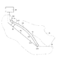
本発明の第二十一実施形態による「ペダル装置」としてのアクセル装置21を図23に示す。アクセル装置21は、車体26の内壁面261から離れる方向に突出するよう湾曲した形状をなしているペダルパッド41、歪みゲージ32、コネクタ33、演算部34、および、ヒステリシス機構部30を有する。これにより、第二十一実施形態によるアクセル装置21は、第一実施形態の効果(a)、第五実施形態の効果(e)、および、第十九実施形態の効果(l)を奏する。
FIG. 23 shows an
(第二十二実施形態)
次に、本発明の第二十二実施形態によるペダル装置を図24に基づいて説明する。第二十二実施形態は、歪みゲージが設けられる位置が第二十一実施形態と異なる。
(Twenty-second embodiment)
Next, a pedal system according to a twenty second embodiment of the present invention will be described with reference to FIG. The twenty-second embodiment differs from the twenty-first embodiment in the position where the strain gauge is provided.
本発明の第二十二実施形態による「ペダル装置」としてのアクセル装置22を図24に示す。アクセル装置22は、ペダルパッド41、ペダルパッド41の裏面412側に設けられる歪みゲージ42、コネクタ33、演算部34、および、ヒステリシス機構部30を有する。これにより、第二十二実施形態によるアクセル装置22は、第一実施形態の効果(a)、第三実施形態の効果(c)、(d)、第五実施形態の効果(e)、および、第十九実施形態の効果(l)を奏する。
FIG. 24 shows an
(第二十三実施形態)
次に、本発明の第二十三実施形態によるペダル装置を図25に基づいて説明する。第二十三実施形態は、歪みゲージの数および設けられる場所が第一実施形態と異なる。
(Twenty-third embodiment)
Next, a pedal system according to a twenty-third embodiment of the present invention will be described with reference to FIG. The twenty-third embodiment differs from the first embodiment in the number of strain gauges and the place where they are provided.
本発明の第二十三実施形態による「ペダル装置」としてのアクセル装置23を図25に示す。アクセル装置23は、ペダルパッド31、「変位量検出部」としての歪みゲージ321、322、323、324、コネクタ33、および、演算部44を有する。
FIG. 25 shows an
歪みゲージ321、322、323、324は、ペダルパッド31の表面311に設けられている。歪みゲージ321、322、323、324は、図25に示すように、表面311の四方に配置されている。
アクセル装置23では、歪みゲージ321は、ペダルパッド31に向かって下側の略中央に設けられている。歪みゲージ322は、ペダルパッド31に向かって上側の略中央に設けられている。歪みゲージ323は、ペダルパッド31に向かって左側の略中央に設けられている。歪みゲージ324は、ペダルパッド31に向かって右側の略中央に設けられている。歪みゲージ321、322、323、324のそれぞれは、それぞれが設けられている部位のペダルパッド31の変位量を検出し、当該変位量に応じた電気信号をコネクタ33に出力する。
The strain gauges 321, 322, 323, 324 are provided on the
In the
演算部44は、コネクタ33が出力する電気信号に基づいてペダルパッド31の変位量を算出する。このとき、演算部44では、歪みゲージ321、322、323、324のそれぞれが検出したペダルパッド31の変位量のそれぞれについて、異なる制御を行うよう電子制御装置に制御信号を伝達する。
The
アクセル装置23では、例えば、歪みゲージ321が検出する歪みゲージ321が設けられている部位のペダルパッド31の変位量は、アクセル装置23が搭載されている車両のブレーキの操作量としての制御信号を電子制御装置に伝達する。同様に、歪みゲージ322が検出するペダルパッド31の変位量は、車両のアクセルの操作量としての制御信号を電子制御装置に伝達する。また、歪みゲージ322が検出するペダルパッド31の変位量は、車両のクラッチの操作量としての制御信号を電子制御装置に伝達する。また、歪みゲージ324が検出するペダルパッド31の変位量は、車両のクルーズコントロールのオンオフ制御を行う制御信号として電子制御装置に伝達する。
In the
第二十三実施形態によるアクセル装置23は、第一実施形態の効果(a)を奏する。
また、第二十三実施形態によるアクセル装置23では、一つのペダルパッド31の表面311の異なる位置に複数の歪みゲージ321、322、323、324を配置することによって、一つのペダルパッド31上での踏み込み操作によって種々の操作をおこなうことができる。
The
Further, in the
(その他の実施形態)
上述の実施形態では、「ペダル装置」は、車両が有するスロットルバルブの駆動を制御するアクセル装置であるとした。しかしながら、本発明の「ペダル装置」が適用される分野はこれに限定されない。例えば、ブレーキやクラッチの操作に適用されてもよく、操作者の足の踏み込み量によって種々の駆動を制御する分野に適用することができる。
(Other embodiments)
In the above-described embodiment, the “pedal device” is the accelerator device that controls the drive of the throttle valve of the vehicle. However, the field to which the “pedal device” of the present invention is applied is not limited to this. For example, it may be applied to the operation of a brake or a clutch, and may be applied to the field of controlling various drives depending on the amount of depression of the operator's foot.
第二実施形態では、演算部は、二つの電気信号に基づいて算出された二つの変位量の最大値をペダルパッドの変位量とし、算出された二つの変位量の最大値に基づいて運転者の踏み込み量を算出するとした。しかしながら、演算部における演算内容をこれに限定されない。二つの電気信号に基づいて算出された二つの変位量の平均値をペダルパッドの変位量とし、算出された二つの変位量の平均値に基づいて運転者の踏み込み量を算出してもよい。また、演算部における演算方法はこれに限定されない。 In the second embodiment, the calculation unit sets the maximum value of the two displacement amounts calculated based on the two electric signals as the displacement amount of the pedal pad, and the driver based on the maximum value of the calculated two displacement amounts. I decided to calculate the amount of depression. However, the calculation content in the calculation unit is not limited to this. An average value of the two displacement amounts calculated based on the two electric signals may be used as the displacement amount of the pedal pad, and the depression amount of the driver may be calculated based on the average value of the calculated two displacement amounts. Further, the calculation method in the calculation unit is not limited to this.
第二、四実施形態では、一つのペダルパッドに二つの歪みゲージを設けるとした。また、第二十三実施形態では、一つのペダルパッドに四つの歪みゲージを設けるとした。歪みゲージの数はこれに限定されない。 In the second and fourth embodiments, one pedal pad is provided with two strain gauges. Also, in the twenty-third embodiment, one pedal pad is provided with four strain gauges. The number of strain gauges is not limited to this.
第十一、十二実施形態では、「伸縮部材」は、ウレタン部材であるとした。また、第十三、十四実施形態では、「伸縮部材」は、ばねであるとした。しかしながら、「伸縮部材」はこれに限定されない。ペダルパッドの動きに合わせて伸縮可能な材料から形成されているか、または、ペダルパッドの動きに合わせて伸縮可能な形状であればよい。 In the eleventh and twelfth embodiments, the "elastic member" is a urethane member. In addition, in the thirteenth and fourteenth embodiments, the "expandable member" is a spring. However, the “stretchable member” is not limited to this. It may be formed of a material that can expand and contract according to the movement of the pedal pad, or may have a shape that can expand and contract according to the movement of the pedal pad.
第二十三実施形態では、四つの歪みゲージのそれぞれは、ブレーキ、アクセル、クラッチ、および、クルーズコントロールを操作する機能をもつとした。しかしながら、歪みゲージが持つ機能はこれに限定されない。例えば、がに股や内股など運転者個々人の体型や歩き方によって靴底の形状が異なる場合、ペダルパッドに向かって左右いずれかに設けられている歪みゲージにブレーキやアクセルを操作する機能をもたせてもよい。 In the twenty-third embodiment, each of the four strain gauges has a function of operating a brake, an accelerator, a clutch, and a cruise control. However, the function of the strain gauge is not limited to this. For example, if the shape of the sole is different depending on the body shape and walking style of the driver, such as the crotch or inner crotch, even if the strain gauges provided on either the left or right of the pedal pad have the function of operating the brake or accelerator. Good.
以上、本発明はこのような実施形態に限定されるものではなく、その要旨を逸脱しない範囲で種々の形態で実施可能である。 As described above, the present invention is not limited to such an embodiment, and can be implemented in various forms without departing from the gist thereof.
1、2、3、4、5、6、7、8、9、10、11、12、13、14、15、16、17、18、19、20、21、22、23・・・アクセル装置(ペダル装置)
31、41、51、61・・・ペダルパッド
32、321、322、323、324、37、38、42、47、48・・・歪みゲージ(変位量検出部)
F1、F5、F7、F9、F11、F13・・・踏み込みの方向
1, 2, 3, 4, 5, 6, 7, 8, 9, 10, 11, 12, 13, 14, 15, 16, 17, 18, 19, 20, 21, 22, 23 ... Accelerator device (Pedal device)
31, 41, 51, 61 ...
F1, F5, F7, F9, F11, F13 ... Depression direction
Claims (10)
前記ペダルパッドの複数の箇所に設けられ、前記ペダルパッドの変位量を検出し、当該変位量に応じた信号を出力する同種の複数の変位量検出部(321、322、323、324、37、38、47、48)と、
を備え、
前記変位量検出部は、前記ペダルパッドの表面または裏面に沿った方向の伸縮を検出し、前記踏み込みの方向の変位量に換算して出力する歪みゲージであるペダル装置。 A pedal pad (31, 41, 51, 61) which is formed of a flexible material and is deformable in the direction of the depression (F1, F5, F7, F9, F11, F13) by the depression of the operator. ,
Plural displacement amount detection units (321, 322, 323, 324, 37) of the same type, which are provided at a plurality of locations of the pedal pad, detect displacement amounts of the pedal pads, and output signals according to the displacement amounts. 38, 47, 48),
Equipped with
The displacement detecting unit, the detecting expansion and contraction of the direction along the surface or the back surface of the pedal pad, Oh Ru pedal device in the strain gauge output in terms of the displacement amount in the direction of the depression.
Priority Applications (5)
| Application Number | Priority Date | Filing Date | Title |
|---|---|---|---|
| JP2016189181A JP6686824B2 (en) | 2016-09-28 | 2016-09-28 | Pedal device |
| PCT/JP2017/027377 WO2018061451A1 (en) | 2016-09-28 | 2017-07-28 | Pedal device |
| CN201780058824.6A CN109791420B (en) | 2016-09-28 | 2017-07-28 | Pedal device |
| DE112017004866.4T DE112017004866T5 (en) | 2016-09-28 | 2017-07-28 | pedal device |
| US16/361,326 US10860047B2 (en) | 2016-09-28 | 2019-03-22 | Pedal device |
Applications Claiming Priority (1)
| Application Number | Priority Date | Filing Date | Title |
|---|---|---|---|
| JP2016189181A JP6686824B2 (en) | 2016-09-28 | 2016-09-28 | Pedal device |
Publications (3)
| Publication Number | Publication Date |
|---|---|
| JP2018055316A JP2018055316A (en) | 2018-04-05 |
| JP2018055316A5 JP2018055316A5 (en) | 2019-01-10 |
| JP6686824B2 true JP6686824B2 (en) | 2020-04-22 |
Family
ID=61762679
Family Applications (1)
| Application Number | Title | Priority Date | Filing Date |
|---|---|---|---|
| JP2016189181A Active JP6686824B2 (en) | 2016-09-28 | 2016-09-28 | Pedal device |
Country Status (5)
| Country | Link |
|---|---|
| US (1) | US10860047B2 (en) |
| JP (1) | JP6686824B2 (en) |
| CN (1) | CN109791420B (en) |
| DE (1) | DE112017004866T5 (en) |
| WO (1) | WO2018061451A1 (en) |
Families Citing this family (7)
| Publication number | Priority date | Publication date | Assignee | Title |
|---|---|---|---|---|
| JP6572858B2 (en) * | 2016-09-28 | 2019-09-11 | 株式会社デンソー | Pedal device |
| US10888383B2 (en) * | 2018-07-17 | 2021-01-12 | Verb Surgical Inc. | Robotic surgical pedal with integrated foot sensor |
| DE102018219487B4 (en) * | 2018-11-15 | 2021-07-29 | Audi Ag | Device for actuating brakes and accelerator in a vehicle |
| DE112020002307T5 (en) | 2019-05-09 | 2022-02-17 | Cts Corporation | VEHICLE BRAKE PEDAL WITH PEDAL RESISTANCE ASSEMBLY AND FORCE/POSITION SENSOR |
| KR20200132430A (en) * | 2019-05-17 | 2020-11-25 | 현대자동차주식회사 | Method and system for accelerator pedal guidance of electric vehicle |
| KR102252038B1 (en) * | 2019-06-21 | 2021-05-14 | 세메스 주식회사 | Apparatus for calculating injection quantity of fluid and stocker system including the same |
| KR20230155056A (en) * | 2022-05-02 | 2023-11-10 | 현대자동차주식회사 | Electronic pedal apparatus |
Family Cites Families (26)
| Publication number | Priority date | Publication date | Assignee | Title |
|---|---|---|---|---|
| JPS61171837A (en) | 1985-01-25 | 1986-08-02 | Molten Corp | Electronic accelerator |
| DE3710256A1 (en) * | 1987-03-28 | 1988-10-13 | Wabco Westinghouse Fahrzeug | SET POINTS |
| US4970486A (en) * | 1989-10-06 | 1990-11-13 | Quadrastat Corporation | Foot operated control producing electrical signals |
| DE4325940C1 (en) * | 1993-08-03 | 1994-12-01 | Daimler Benz Ag | Method for determining the start and end of an automatic braking process |
| US6571662B1 (en) * | 1999-12-06 | 2003-06-03 | Volvo Car Corporation | Method and apparatus for vehicular control pedals |
| US20040040408A1 (en) * | 2002-08-27 | 2004-03-04 | Delphi Technologies Inc. | Pedal emulator assembly and method |
| JP4600083B2 (en) * | 2005-02-28 | 2010-12-15 | 三菱自動車エンジニアリング株式会社 | Pedal pad |
| US20070296268A1 (en) * | 2006-06-27 | 2007-12-27 | Shaw Schuyler S | Piezoelectric composite brake pedal feel emulating system |
| EP1961461A1 (en) * | 2007-02-23 | 2008-08-27 | Brunswick Corporation | Flexible pedal |
| US20080223171A1 (en) * | 2007-03-16 | 2008-09-18 | Noboru Fujiwara | Operating pedal device having load sensor for vehicle, and operating device having load sensor |
| JP2009251773A (en) * | 2008-04-03 | 2009-10-29 | Toyota Motor Corp | Stepping type operation apparatus |
| US20100071500A1 (en) | 2008-09-22 | 2010-03-25 | Mazda Motor Corporation | Pedal device of automotive vehicle |
| JP4858518B2 (en) * | 2008-09-22 | 2012-01-18 | マツダ株式会社 | Automotive pedal equipment |
| US8522640B2 (en) * | 2008-10-30 | 2013-09-03 | GM Global Technology Operations LLC | Lightweight cantilever control system |
| CN101655352B (en) * | 2009-09-15 | 2011-02-09 | 西安交通大学 | Measurement method of three-dimensional speckle strain measurement device |
| JP5321494B2 (en) | 2010-02-16 | 2013-10-23 | トヨタ自動車株式会社 | Vehicles that automatically correct for sensitivity differences due to pedal position differences |
| JP5672078B2 (en) * | 2011-03-08 | 2015-02-18 | 日産自動車株式会社 | Brake pedal device for standing posture |
| JP5492360B2 (en) * | 2011-10-31 | 2014-05-14 | 豊田鉄工株式会社 | Pedal operation amount detection device |
| JP2013119264A (en) * | 2011-12-06 | 2013-06-17 | Mikuni Corp | Accelerator pedal apparatus |
| CN103507795B (en) * | 2012-06-29 | 2016-01-13 | 比亚迪股份有限公司 | Brake pedal control method, control setup and there is the electronlmobil of this device |
| CN103115711B (en) * | 2013-01-25 | 2015-01-28 | 中国兵器工业第二0二研究所 | Method for testing braking force of muzzle brake |
| US9562820B2 (en) * | 2013-02-28 | 2017-02-07 | Mks Instruments, Inc. | Pressure sensor with real time health monitoring and compensation |
| JP5780267B2 (en) | 2013-07-02 | 2015-09-16 | 株式会社デンソー | Accelerator device |
| JP6693739B2 (en) | 2015-03-27 | 2020-05-13 | パナソニック インテレクチュアル プロパティ コーポレーション オブ アメリカPanasonic Intellectual Property Corporation of America | Display control method, display control program, and display device |
| US20180058837A1 (en) * | 2016-08-24 | 2018-03-01 | Knowles Electronics, Llc | User interface incorporating strain gauges |
| JP6572858B2 (en) * | 2016-09-28 | 2019-09-11 | 株式会社デンソー | Pedal device |
-
2016
- 2016-09-28 JP JP2016189181A patent/JP6686824B2/en active Active
-
2017
- 2017-07-28 CN CN201780058824.6A patent/CN109791420B/en active Active
- 2017-07-28 WO PCT/JP2017/027377 patent/WO2018061451A1/en active Application Filing
- 2017-07-28 DE DE112017004866.4T patent/DE112017004866T5/en active Pending
-
2019
- 2019-03-22 US US16/361,326 patent/US10860047B2/en active Active
Also Published As
| Publication number | Publication date |
|---|---|
| DE112017004866T5 (en) | 2019-06-27 |
| US10860047B2 (en) | 2020-12-08 |
| CN109791420B (en) | 2021-08-13 |
| US20190220052A1 (en) | 2019-07-18 |
| WO2018061451A1 (en) | 2018-04-05 |
| CN109791420A (en) | 2019-05-21 |
| JP2018055316A (en) | 2018-04-05 |
Similar Documents
| Publication | Publication Date | Title |
|---|---|---|
| JP6686824B2 (en) | Pedal device | |
| JP6572858B2 (en) | Pedal device | |
| JP2018052252A5 (en) | ||
| KR20180008303A (en) | Methods and apparatuses for endstop diminishment solutions in haptically-enabled controller devices | |
| US20080134801A1 (en) | Tactile sensing device for human robot interaction and method thereof | |
| JP6878988B2 (en) | Switching device and keyboard device | |
| WO2017033782A1 (en) | Reaction force generation device and electronic musical instrument keyboard device | |
| EP1733179A2 (en) | Drive-by-wire assembly with strain gauge | |
| US8392023B2 (en) | Photo-interrupter based force sensing handle and method of use | |
| EP1730618A2 (en) | Drive-by-wire assembly with force measuring sensor | |
| JP2013540642A5 (en) | ||
| JP6731302B2 (en) | Operating device | |
| JP2003312458A (en) | Stroke simulator | |
| JP5919923B2 (en) | Pedal device for percussion instruments | |
| JP2006281803A (en) | Pedal device and automobile provided with it | |
| US20230302897A1 (en) | Device for detecting a driver demand | |
| JP6303084B1 (en) | Driving assistance device | |
| JP6823292B2 (en) | Vehicle control device | |
| JP3244997U (en) | Pedal force detection mechanism | |
| KR102077687B1 (en) | Pedal apparatus of variable pedal effort | |
| JP4465470B2 (en) | Operating device and operating method therefor | |
| JP5844592B2 (en) | Pedal device | |
| US11756517B2 (en) | Multi-axis foot pedal for electric musical instruments | |
| JP6528806B2 (en) | Vehicle control device | |
| KR101848315B1 (en) | Appararus for controlling brake of vehicle and method thereof |
Legal Events
| Date | Code | Title | Description |
|---|---|---|---|
| A521 | Request for written amendment filed |
Free format text: JAPANESE INTERMEDIATE CODE: A523 Effective date: 20181119 |
|
| A621 | Written request for application examination |
Free format text: JAPANESE INTERMEDIATE CODE: A621 Effective date: 20181119 |
|
| A131 | Notification of reasons for refusal |
Free format text: JAPANESE INTERMEDIATE CODE: A131 Effective date: 20190611 |
|
| A521 | Request for written amendment filed |
Free format text: JAPANESE INTERMEDIATE CODE: A523 Effective date: 20190723 |
|
| A02 | Decision of refusal |
Free format text: JAPANESE INTERMEDIATE CODE: A02 Effective date: 20191119 |
|
| A521 | Request for written amendment filed |
Free format text: JAPANESE INTERMEDIATE CODE: A523 Effective date: 20200120 |
|
| A911 | Transfer to examiner for re-examination before appeal (zenchi) |
Free format text: JAPANESE INTERMEDIATE CODE: A911 Effective date: 20200129 |
|
| TRDD | Decision of grant or rejection written | ||
| A01 | Written decision to grant a patent or to grant a registration (utility model) |
Free format text: JAPANESE INTERMEDIATE CODE: A01 Effective date: 20200303 |
|
| A61 | First payment of annual fees (during grant procedure) |
Free format text: JAPANESE INTERMEDIATE CODE: A61 Effective date: 20200316 |
|
| R151 | Written notification of patent or utility model registration |
Ref document number: 6686824 Country of ref document: JP Free format text: JAPANESE INTERMEDIATE CODE: R151 |
|
| R250 | Receipt of annual fees |
Free format text: JAPANESE INTERMEDIATE CODE: R250 |
|
| R250 | Receipt of annual fees |
Free format text: JAPANESE INTERMEDIATE CODE: R250 |