JP6676552B2 - MAG welding wire for high strength thin steel sheet and pulse MAG welding method using the same - Google Patents
MAG welding wire for high strength thin steel sheet and pulse MAG welding method using the same Download PDFInfo
- Publication number
- JP6676552B2 JP6676552B2 JP2017001306A JP2017001306A JP6676552B2 JP 6676552 B2 JP6676552 B2 JP 6676552B2 JP 2017001306 A JP2017001306 A JP 2017001306A JP 2017001306 A JP2017001306 A JP 2017001306A JP 6676552 B2 JP6676552 B2 JP 6676552B2
- Authority
- JP
- Japan
- Prior art keywords
- pulse
- welding
- wire
- mag welding
- thin steel
- Prior art date
- Legal status (The legal status is an assumption and is not a legal conclusion. Google has not performed a legal analysis and makes no representation as to the accuracy of the status listed.)
- Active
Links
Images

Landscapes
- Arc Welding In General (AREA)
Description
本発明は、引張強度が780MPa以上の高強度薄鋼板のMAG溶接用ワイヤ及びこれを使用したパルスMAG溶接方法に関し、特に板厚が1.2〜3.2mmの高強度薄鋼板の重ね継手部やT継手部を溶接するに際してアークを安定させ、スパッタ発生量及びスラグ生成量が少なく、ギャップが大きい場合においても溶接金属の垂れ落ちが生じ難く、ビード外観が良好で、かつ良好な溶接金属の強度を得る上で好適な高強度薄鋼板のMAG溶接用ワイヤ及びこれを使用したパルスMAG溶接方法に関する。 TECHNICAL FIELD The present invention relates to a MAG welding wire for a high-strength thin steel plate having a tensile strength of 780 MPa or more and a pulse MAG welding method using the same, and particularly to a lap joint portion of a high-strength thin steel plate having a plate thickness of 1.2 to 3.2 mm. When welding a T-joint or a T-joint, the arc is stabilized, the amount of spatter generated and the amount of slag generated are small, and even when the gap is large, dripping of the weld metal is unlikely to occur, the bead appearance is good, and a good weld metal is obtained. The present invention relates to a high strength thin steel sheet MAG welding wire suitable for obtaining strength and a pulse MAG welding method using the same.
近年、地球環境保全の見地から、自動車の燃費向上が重要な課題となっており、車体材料の高強度化のために使用鋼板の薄肉化が進められている。例えば特許文献1には、引張最大強度780MPa以上の高強度鋼板で衝突時の衝撃吸収能に優れた自動車用鋼板が開示されている。また特許文献2には、引張強さが980MPa以上の高強度鋼板で成形性の優れた自動車用鋼板が開示されている。
In recent years, from the viewpoint of global environmental conservation, improvement in fuel efficiency of automobiles has become an important issue, and the use of thin steel plates has been promoted in order to increase the strength of body materials. For example, Patent Literature 1 discloses a high-strength steel plate having a maximum tensile strength of 780 MPa or more, and a steel plate for automobiles having excellent shock absorbing ability at the time of collision.
一方、溶接用ワイヤも前記高強度鋼板の溶接に適用するために高強度の材料が求められており、特許文献3には、薄板高張力鋼板(690MPa鋼級)をワイヤ成分、溶接電圧、溶接電流、溶接速度及びシールドガスを限定して溶接し、溶接継手の疲労強度を向上する技術が開示されている。
On the other hand, a high strength material is also required for the welding wire to be applied to the welding of the high strength steel sheet.
また特許文献4には、引張強さ980MPa以上の高強度薄鋼板の溶接において、溶け込み深さ、溶接金属のビッカース硬さとワイヤのPcm値を限定することによって、溶接部の低温割れを抑制する技術が開示されている。 Patent Literature 4 discloses a technique for suppressing low-temperature cracking of a welded portion by limiting the penetration depth, the Vickers hardness of a weld metal, and the Pcm value of a wire when welding a high-strength thin steel plate having a tensile strength of 980 MPa or more. Is disclosed.
しかし、特許文献3及び特許文献4に記載の溶接用ワイヤを用いて、高強度薄鋼板をMAG溶接した場合、アークが不安定で溶接ビードの広がりがなく、ビード止端部のなじみが不良となりやすいという問題がある。
However, when a high-strength thin steel plate is subjected to MAG welding using the welding wires described in
このため、高速度でアークが安定した溶接を行うためにパルスを付与したパルスMAG溶接が提案されている。 For this reason, pulse MAG welding in which a pulse is applied to perform stable welding at a high speed with an arc has been proposed.
パルスMAG溶接とは、溶接電流として平均電流値より高電流となるピーク電流と平均電流値より低電流としたベース電流を周期的に流す溶接方法である。これによりピーク電流期間では一定に送給されている溶接ワイヤを電磁ピンチ力などの作用で溶滴状態に溶融させ、ベース電流期間中にこの溶滴を溶融池に安定的に移行させるので、高速溶接時にアンダーカットを抑制するために溶接中のアーク電圧が低くなった場合においても溶滴が溶融池と短絡することなくスムーズに溶融池へ移行させることができる。 Pulse MAG welding is a welding method in which a peak current that is higher than the average current value and a base current that is lower than the average current value are periodically passed as welding currents. As a result, the welding wire fed constantly during the peak current period is melted into a droplet state by the action of electromagnetic pinch force, etc., and during the base current period, the droplet is stably transferred to the molten pool. Even when the arc voltage during welding becomes low in order to suppress the undercut during welding, the droplet can be smoothly transferred to the molten pool without short-circuiting with the molten pool.
このように、パルス溶接電源を適用することにより、パルスMAG溶接においてピーク電流、ピーク時間、アーク電圧の積からなる溶融エネルギーに対応したワイヤ送給量毎の溶滴生成量にする。すなわち、1回のパルスピーク電流時に1個の溶滴を生成させ、ベース電流期間に溶滴を溶融池に規則的に移行させる1パルス−1ドロップ移行となるパルス条件とするにより、溶滴はスムーズに溶融池に移行してスパッタ発生量が低減される。このため溶接電源は、溶接ワイヤの送給速度に対応してパルスの周波数を数十Hz〜300Hz程度まで変化させることが可能となっている。 As described above, by applying the pulse welding power source, in the pulse MAG welding, the droplet generation amount for each wire feed amount corresponding to the melting energy consisting of the product of the peak current, the peak time, and the arc voltage is obtained. That is, a droplet is generated by one pulse at the time of one pulse peak current, and the pulse condition is 1 pulse-1 drop transition in which the droplet is regularly transferred to the molten pool during the base current period. Smooth transition to the molten pool reduces the amount of spatter generated. Therefore, the welding power source can change the frequency of the pulse from several tens Hz to about 300 Hz in accordance with the feeding speed of the welding wire.
一方、ピーク電流、ピーク時間、アーク電圧の積からなるワイヤを溶融するエネルギーがワイヤ送給量と不均衡になると、溶滴の形成がベース電流期間となり、溶滴形成がピーク電流期間の初期時に終了した溶滴はスムーズに移行できなくなり、スパッタとして飛散する。また溶滴移行時期がベース電流期間およびピーク電流期間に不連続に発生することになり、スパッタとして飛散するばかりでなく不均一なビード形状となる。 On the other hand, when the energy for melting the wire, which is the product of the peak current, the peak time, and the arc voltage, becomes imbalanced with the wire feed rate, the droplet formation becomes the base current period, and the droplet formation occurs at the beginning of the peak current period. The completed droplet cannot be transferred smoothly and scatters as spatter. In addition, the droplet transfer time is discontinuously generated during the base current period and the peak current period, so that not only scattering as spatters but also non-uniform bead shapes occur.
特にガスシールドアーク溶接での高速度溶接においてはアンダーカットが発生し易く、これを抑制する方法としてはアーク電圧を低くした溶接条件を採用することが一般的であるが、アークの広がりが小さくなるのでビード幅も狭くなり、ビード幅の広い良好な継手の形成が困難となる。また薄鋼板の構造物の形状は複雑化し、溶接部においても継手部の形状は複雑で溶接狙い精度が要求され、ワイヤ狙い精度の不安定状態により鋼板の溶け落ちや溶け込み不良、さらにはアーク状態の安定性劣化によるスパッタの多発、ビード形状の不良などの要因となる。 In particular, undercutting easily occurs in high-speed welding in gas shielded arc welding, and as a method of suppressing this, it is common to employ welding conditions in which the arc voltage is reduced, but the spread of the arc is reduced. Therefore, the bead width also becomes narrow, and it becomes difficult to form a good joint having a wide bead width. In addition, the shape of thin steel plate structures is becoming more complicated, and the shape of the joints is also complicated at the welded parts, requiring high precision in aiming for welding. This causes many spatters due to the deterioration of the stability of the alloy, and a defect in the bead shape.
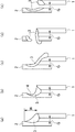
図1(a)、(b)、(c)、(d)、(e)に薄鋼板の重ね継手部の横向姿勢においてギャップがある場合のビード形成状態の例を示す。前板1に対して後側に後板2を位置させ、この前板1及び後板2にそれぞれ溶接金属3を形成させる。この前板1と後板2との間にはギャップGが形成されている。図1(a)は、溶け落ちやビードの垂れおよびアンダーカットがなくビード幅Wが大きく良好な溶接金属3が得られた例を示す。図1(b)は、アンダーカット4が生じた例を示す。図1(c)は、溶融金属3が前板1側に垂れた例を示す。図1(d)は、鋼板(後板2)が溶け落ちた例を示す。図1(e)は、溶融金属3が前板1と後板2の間のギャップG内に垂れ落ちた例を示す。
1 (a), (b), (c), (d), and (e) show examples of a bead formation state in a case where there is a gap in a lateral orientation of a lap joint portion of a thin steel plate. The
図1(b)に示すアンダーカット4は、アーク電圧が高い場合に生じる。図1(c)に示す溶接金属3の前板1側への垂れは、図3に示すワイヤ狙い位置6が前板1の前面側61になった場合に生じやすい。図1(d)に示す鋼板(後板2)の溶け落ちは、図3に示すワイヤ狙い位置6が後板側62になった場合に生じやすい。図1(e)に示す溶接金属3のギャップG内への垂れ落ちは、ギャップG自体が大きい場合に生じやすくなる。このように、ワイヤ狙い位置が変動した場合は、溶融金属3の垂れや、後板2側の鋼板の溶け落ちが生ずるばかりでなく、重ね継手部のギャップGが大きい場合、溶融金属3が前板1と後板2との間で架橋できなくなり、良好な溶接ビード形成が困難になるという問題点があった。
The undercut 4 shown in FIG. 1B occurs when the arc voltage is high. The dripping of the
従来、高強度鋼板のパルスMAG溶接用ワイヤとして、例えば特許文献5には、薄板高張力鋼板(690MPa鋼級)をワイヤ成分、シールドガス組成及びパルス付与条件を限定して溶接し、溶接金属の機械的性質を良好にすることができると共にスパッタの発生量が少なく溶接作業性に優れる技術が開示されている。
Conventionally, as a wire for pulse MAG welding of a high-strength steel sheet, for example, in
しかし、特許文献5の開示技術においても、アークが安定してビード幅が広く、ビード止端部のなじみが良好な溶接金属を得ることができず、溶接金属の強度も低くなってしまう問題点があった。
However, even in the technology disclosed in
そこで本発明は、上述した問題点に鑑みて案出されたものであり、板厚が1.2〜3.2mmであり、引張強度が780MPa以上の高強度薄鋼板の重ね継手部やT継手部を溶接するに際してアークが安定して、スパッタ発生量及びスラグ生成量が少なく、ギャップが大きい場合においても溶接金属の垂れ落ちが生じ難く、ビード外観が良好で、かつ良好な溶接金属の強度が得られる高強度薄鋼板のMAG溶接用ワイヤ及びこれを使用したパルスMAG溶接方法を提供することを目的とする。 Therefore, the present invention has been devised in view of the above-mentioned problems, and a lap joint or a T-joint of a high-strength thin steel plate having a plate thickness of 1.2 to 3.2 mm and a tensile strength of 780 MPa or more. When welding the parts, the arc is stable, the amount of spatter generation and the amount of slag generated are small, even if the gap is large, the weld metal does not easily droop, the bead appearance is good, and the strength of the weld metal is good. An object of the present invention is to provide a MAG welding wire for a high-strength thin steel sheet and a pulse MAG welding method using the same.
本発明の要旨は、
(1) 厚さ1.2〜3.2mmである高強度薄鋼板のMAG溶接用ワイヤにおいて、ワイヤ全質量に対する質量%でC:0.20超〜0.50%、Si:0.05〜0.20%、Mn:1.5〜2.5%、Mo:0.3〜0.6%を含有し、P:0.03%以下、S:0.03%以下であり、残部はFe及び不可避不純物からなることを特徴とする高強度薄鋼板のMAG溶接用ワイヤである。
The gist of the present invention is:
(1) In a MAG welding wire of a high-strength thin steel sheet having a thickness of 1.2 to 3.2 mm, C: more than 0.20 to 0.50%, Si: 0.05 to 100% by mass based on the total mass of the wire. 0.20%, Mn: 1.5 to 2.5%, Mo: 0.3 to 0.6%, P: 0.03% or less, S: 0.03% or less, the balance being A high-strength thin steel sheet MAG welding wire comprising Fe and inevitable impurities.
(2)ワイヤ全質量に対する質量%で、AlとTiの1種又は2種以上の合計:0.15%以下をさらに含有することを特徴とする(1)記載の高強度薄鋼板のMAG溶接用ワイヤである。 (2) MAG welding of a high-strength thin steel sheet according to (1), further containing 0.15% or less of one or more of Al and Ti in mass% based on the total mass of the wire. Wire.
(3)(1)または(2)のいずれかに記載の高強度薄鋼板のMAG溶接用ワイヤを使用したパルスMAG溶接方法において、パルスピーク電流(Ip):400〜600A、パルスベース電流(Ib):30〜80Aとし、前記パルスピーク電流(Ip)とパルスピーク時間(Tp)が下記式(1)を満足するパルスを付加して溶接することを特徴とするパルスMAG溶接方法である。
400≦Ip(A)×Tp(msec) ≦800・・・・・(1)
(3) In the pulse MAG welding method using a MAG welding wire for a high-strength thin steel sheet according to any of (1) or (2), a pulse peak current (Ip): 400 to 600 A, and a pulse base current (Ib) ): 30 to 80 A, and a pulse MAG welding method characterized by adding a pulse whose pulse peak current (Ip) and pulse peak time (Tp) satisfy the following expression (1) to perform welding.
400 ≦ Ip (A) × Tp (msec) ≦ 800 (1)
本発明の高強度薄鋼板のMAG溶接用ワイヤ及びこれを使用したパルスMAG溶接方法によれば、板厚が1.2〜3.2mmの引張強度が780MPa以上の高強度薄鋼板の重ね継手部やT継手部を溶接するに際してアークが安定して、スパッタ発生量及びスラグ生成量が少なく、ギャップが大きい場合においても溶接金属の垂れ落ちが生じ難く、ビード外観が良好で、かつ良好な溶接金属の強度が得られるなど、高能率に高品質な溶接部が得られる。 According to the high-strength thin steel sheet MAG welding wire and the pulse MAG welding method using the same according to the present invention, a lap joint portion of a high-strength thin steel sheet having a plate thickness of 1.2 to 3.2 mm and a tensile strength of 780 MPa or more is provided. The arc is stable when welding a T-joint or a T-joint, the amount of spatter and slag generated is small, and even when the gap is large, the weld metal is unlikely to sag, the bead appearance is good, and the weld metal is good. Thus, a highly efficient and high quality weld can be obtained.
本発明者らは、上述した問題点を解決するために、薄鋼板の横向姿勢による重ね継手とし、各種成分のソリッドワイヤを用いてMAG溶接及び各種パルス条件で60cm/min以上の溶接速度で溶接を行い、アークの安定性、溶接ビード幅、溶接欠陥の有無及び溶接金属の硬さについて詳細に検討した結果、次の知見を得た。 In order to solve the above-mentioned problems, the present inventors made a lap joint using a thin steel sheet in a lateral orientation, and performed MAG welding using solid wires of various components and welding at a welding speed of 60 cm / min or more under various pulse conditions. The following findings were obtained as a result of a detailed study of arc stability, weld bead width, the presence or absence of welding defects, and the hardness of the weld metal.
(1)ワイヤ組成は、C及びMnの含有量の増加、Siの含有量の低減によって溶滴の細粒化、アークの安定性向上、溶融金属の粘性及び表面張力の適正化を図り、広幅ビードでスパッタ発生量の少ない溶接ができ、ビード外観が良好で溶接欠陥の無い溶接金属が得られる。また、Cの含有量の増加及びMoの添加によって高強度の溶接金属が得られる。さらに、Al及びTiの添加によってビード止端部のなじみが良好な溶接金属が得られる。 (1) The wire composition is widened by increasing the content of C and Mn and reducing the content of Si to reduce the size of droplets, improve arc stability, and optimize the viscosity and surface tension of the molten metal. Welding with a small amount of spatter can be performed with a bead, and a weld metal having good bead appearance and no welding defects can be obtained. In addition, a high strength weld metal can be obtained by increasing the content of C and adding Mo. Further, by adding Al and Ti, it is possible to obtain a weld metal having a good fit at the bead toe.
(2)上述した組成のワイヤを用いてパルス条件が1パルス−1ドロップの溶滴移行となる領域にすることで、80cm/min以上の高速度の溶接でアーク電圧を低くしても溶滴が溶融池と短絡することがなく移行でき、ギャップが大きい場合においても溶接金属の垂れ落ちが生じ難く、スパッタ発生量が少ないビードが得られる。 (2) By using a wire having the above-described composition, the pulse condition is set to a region where the transition of the droplet is 1 pulse-1 drop, so that the droplet can be dropped even when the arc voltage is reduced by welding at a high speed of 80 cm / min or more. Can be transferred without causing a short circuit with the molten pool, and even when the gap is large, the weld metal is less likely to sag and a bead with a small amount of spatter is obtained.
以下、本発明の高強度薄鋼板のMAG溶接用ワイヤ成分組成及びパルスMAG溶接条件の限定理由について説明する。 Hereinafter, the reasons for limiting the composition of the wire component for MAG welding and the pulse MAG welding conditions of the high-strength thin steel sheet of the present invention will be described.
まず、高強度薄鋼板のMAG溶接用ワイヤ成分組成について説明する。なお、各成分の含有率は、ワイヤ全質量に対する質量%で表すものとし、その質量%に関する記載を単に%と記載する。 First, the composition of the wire component for MAG welding of a high-strength thin steel plate will be described. The content of each component is represented by mass% with respect to the total mass of the wire, and the description of the mass% is simply described as%.
[C:0.20超〜0.50%]
Cは、溶接金属の強度を確保する元素である。またアークを安定化し、溶滴を細粒化する効果がある。本発明においては溶滴の細粒化と広幅ビードを得ることを目的に脱酸元素であるSiの含有量を低くしており、溶融金属の脱酸は主にCによって行う。Cが0.20%以下では、アークが不安定となりビード幅が不均一となる。また、スパッタ発生量が多く溶融金属の垂れが生じる。一方、Cが0.50%を超えると、溶融金属の粘性が劣り耐垂れ性を確保できない。また、スパッタ発生量が増加するばかりでなく、溶接金属を著しく硬化させ耐割れ性が劣化する。したがって、Cは0.20超〜0.50%とする。
[C: more than 0.20 to 0.50%]
C is an element that secures the strength of the weld metal. It also has the effect of stabilizing the arc and making the droplets finer. In the present invention, the content of Si, which is a deoxidizing element, is reduced for the purpose of obtaining fine droplets and obtaining wide beads, and the deoxidation of molten metal is mainly performed by C. If C is 0.20% or less, the arc becomes unstable and the bead width becomes non-uniform. Further, the amount of spatter generated is large, and the molten metal sags. On the other hand, if C exceeds 0.50%, the viscosity of the molten metal is inferior and sag resistance cannot be ensured. In addition, not only the amount of spatters generated increases, but also the weld metal is significantly hardened and the crack resistance is deteriorated. Therefore, C is set to be more than 0.20 to 0.50%.
[Si:0.05〜0.20%]
Siは、溶融金属の粘性及び表面張力を適正化させる効果が大きい元素である。また、溶滴を細粒化すると共に広幅ビードが得られ、アーク電圧を低くした場合においても溶滴が短絡し難く電圧条件の拡大に寄与できる。Siが0.05%未満では、溶融金属の粘性が劣り溶融金属が垂れ、十分な耐ギャップ性が得られない。また、溶滴が大きくなってビード幅が狭くなる。一方、Siが0.20%を超えると、溶滴が大きくなって短絡しやすくなりスパッタ発生の要因になる。また、溶融池の溶融金属が溶接速度に追従できずハンピングビードになりやすい。さらに、スラグが多く生成してビード外観を劣化させる。したがって、Siは0.05〜0.20%とする。
[Si: 0.05 to 0.20%]
Si is an element having a large effect of optimizing the viscosity and surface tension of the molten metal. Further, the droplet can be made finer and a wide bead can be obtained. Even when the arc voltage is lowered, the droplet is less likely to be short-circuited, which can contribute to the expansion of the voltage condition. If Si is less than 0.05%, the viscosity of the molten metal is inferior and the molten metal drips, and sufficient gap resistance cannot be obtained. In addition, the droplet becomes large and the bead width becomes narrow. On the other hand, if the Si content exceeds 0.20%, the droplets become large and short-circuits easily occur, which causes spatter. In addition, the molten metal in the molten pool cannot follow the welding speed and easily becomes a humping bead. Further, a large amount of slag is generated to deteriorate the bead appearance. Therefore, Si is set to 0.05 to 0.20%.
[Mn:1.5〜2.5%]
Mnは、脱酸剤として作用するとともに溶融金属の粘性及び表面張力を適正化させる効果がある。Mnが1.5%未満では、その効果が得られず、溶融金属の粘性及び表面張力が劣化するため、溶融金属が垂れ、十分な耐ギャップ性が得られない。一方、Mnが2.5%を超えると、溶滴が大きくなり短絡しやすくスパッタ発生の要因となる。したがって、Mnは1.5〜2.5%とする。
[Mn: 1.5-2.5%]
Mn acts as a deoxidizing agent and has the effect of optimizing the viscosity and surface tension of the molten metal. If Mn is less than 1.5%, the effect cannot be obtained, and the viscosity and surface tension of the molten metal deteriorate, so that the molten metal sags and sufficient gap resistance cannot be obtained. On the other hand, if Mn exceeds 2.5%, the droplets become large and short-circuits easily occur, which causes spatter. Therefore, Mn is set to 1.5 to 2.5%.
[Mo:0.3〜0.6%]
Moは、溶接金属の組織を微細化して強度を向上させる元素である。またMoを添加することにより、溶滴形成性が良くなり、溶滴移行が安定してスパッタ発生量が少なくなる。Moが0.3%未満では、上記効果が得られない。一方、Moが0.6%を超えると、溶接金属が硬化して耐割れ性が劣化する。また、溶滴形成性が悪く、溶滴移行が不安定でスパッタ発生量が多くなる。したがって、Moは0.3〜0.6%とする。
[Mo: 0.3-0.6%]
Mo is an element that refines the structure of the weld metal to improve the strength. Addition of Mo improves the droplet forming property, stabilizes droplet transfer, and reduces the amount of spatter generated. If Mo is less than 0.3%, the above effects cannot be obtained. On the other hand, if Mo exceeds 0.6%, the weld metal is hardened and the crack resistance is deteriorated. Further, the droplet formation property is poor, the droplet transfer is unstable, and the amount of spatter generated is increased. Therefore, Mo is set to 0.3 to 0.6%.
[P:0.03%以下]
Pは不純物であり、Pの増加により溶接金属の割れを引き起こすので0.03%以下とする。好ましくは、Pは0.015%以下である。
[P: 0.03% or less]
P is an impurity, and the increase in P causes cracking of the weld metal. Preferably, P is not more than 0.015%.
[S:0.03%以下]
Sは不純物であり、Sの増加により溶接金属の割れを引き起こすので0.03%以下とする。好ましくは、Sは0.010%以下である。
[S: 0.03% or less]
S is an impurity, and because the increase in S causes cracks in the weld metal, it is set to 0.03% or less. Preferably, S is 0.010% or less.
[AlとTiの1種又は2種以上の合計:0.15%以下]
AlとTiは、微量の添加でも脱酸元素として作用してブローホール等の気孔発生を抑制する。また、溶接金属と母材とのなじみを改善する効果がある。しかし、AlとTiの1種又は2種以上の合計が0.15%超になると、ビード形状を凸状態にし、ビード幅が狭くなるとともに、スラグが多く生成してビード外観を劣化させる。したがって、AlとTiの1種又は2種以上の合計:0.15%以下とすることが望ましい。なお、脱酸作用及び母材とのなじみを改善する効果を得るためにはAlとTiの1種又は2種以上の合計を0.02〜0.12添加することが好ましい。但し、このAlとTiの含有量が上述した条件を逸脱するものであっても、本発明所期の効果は発揮しえる。
[Total of one or more of Al and Ti: 0.15% or less]
Al and Ti act as deoxidizing elements even when added in small amounts to suppress the generation of pores such as blowholes. Further, there is an effect of improving the familiarity between the weld metal and the base material. However, if the total of one or more of Al and Ti exceeds 0.15%, the bead shape becomes a convex state, the bead width is reduced, and a large amount of slag is generated to deteriorate the bead appearance. Therefore, it is desirable to set the total of one or more of Al and Ti: 0.15% or less. In order to obtain a deoxidizing effect and an effect of improving the conformity with the base material, it is preferable to add 0.02 to 0.12 of one or more of Al and Ti. However, even if the contents of Al and Ti deviate from the conditions described above, the intended effects of the present invention can be exhibited.
さらに、80cm/min以上の高速度の溶接条件でビード幅が広く、しかも垂れない最適パルスMAG条件範囲を検討した結果、1パルス−1ドロップ領域であるパルスピーク電流Ipとパルスピーク時間Tpの領域において、短絡がし難くスパッタ発生量の少ない溶接となり、ワイヤ狙い位置が変動した場合においても広幅ビードが得られる最適のパルスMAG条件範囲を見出した。 Further, the optimum pulse MAG condition range in which the bead width is wide and the dripping is not performed under high-speed welding conditions of 80 cm / min or more was examined. As a result, the region of the pulse peak current Ip and the pulse peak time Tp in one pulse-1 drop region was obtained. In the above, it was found that welding was short and hard to generate a small amount of spatter, and an optimum pulse MAG condition range in which a wide bead was obtained even when the target position of the wire fluctuated.
[パルスピーク電流(Ip):400〜600A]
パルスピーク電流(Ip)が400A未満では、電磁ピンチ効果による溶滴の離脱がスムーズに行われなくなり、アークが不安定となり、ビード幅が狭くなることから、十分な耐ギャップ性が得られない。一方、パルスピーク電流(Ip)が600Aを超えると、アーク力により溶融地が垂れ易くなる。したがって、パルスピーク電流(Ip)は400〜600Aとする。
[Pulse peak current (Ip): 400 to 600 A]
If the pulse peak current (Ip) is less than 400 A, the separation of the droplet by the electromagnetic pinch effect will not be performed smoothly, the arc will be unstable, and the bead width will be narrow, so that sufficient gap resistance cannot be obtained. On the other hand, when the pulse peak current (Ip) exceeds 600 A, the melted material tends to hang down due to the arc force. Therefore, the pulse peak current (Ip) is set to 400 to 600A.
[パルスベース電流(Ib):30〜80A]
パルスベース電流(Ib)は、ベース期間でアークを保持できる電流値が必要となる。パルスベース電流(Ib)が30A未満では、アークが不安定となり、80Aを超えると溶滴の離脱が速やかに行われず、アークが不安定となり、スパッタ発生量が多くなる。したがって、パルスベース電流(Ib)は30〜80Aとする。
[Pulse base current (Ib): 30 to 80 A]
The pulse base current (Ib) requires a current value capable of holding an arc in the base period. If the pulse base current (Ib) is less than 30 A, the arc becomes unstable. If the pulse base current (Ib) exceeds 80 A, the droplet is not rapidly separated, the arc becomes unstable, and the amount of spatter generated increases. Therefore, the pulse base current (Ib) is set to 30 to 80 A.
[400≦Ip(A)×Tp(msec)≦800]
下記式(1)で示すパルス電流(Ip)とパルスピーク時間(Tp)の積(Ip×Tp)で得られる値を限定することによって、ピーク時間の短い領域でアーク電圧が高い場合においても、溶滴の短絡がピーク時及びベース時に適度に生じて溶融金属の垂れが生じ難く、広幅ビードが得られる。パルスピーク電流(Ip)とパルスピーク時間(Tp)の積(Ip×Tp)が400未満では、ピーク電流期間で溶滴を形成するためのエネルギーが不足し十分な溶滴の形成ができず、ビード幅が狭くなることから十分な耐ギャップ性が得られない。またIp×Tpが400未満では、溶融金属が垂れやすくなる。一方、パルスピーク電流(Ip)とパルスピーク時間(Tp)の積が800を超えると、過度に成長した溶滴が短絡しやすくなり再点弧時のアーク力で溶融地が吹き飛ばされることからスパッタ発生量が多くなるとともに溶融金属が垂れやすく、十分な耐ギャプ性が得られない。従ってIp×Tpは、下記式(1)で示される範囲とする。
400≦Ip(A)×Tp(msec)≦800 ・・・・(1)
[400 ≦ Ip (A) × Tp (msec) ≦ 800]
By limiting the value obtained by the product (Ip × Tp) of the pulse current (Ip) and the pulse peak time (Tp) shown in the following equation (1), even when the arc voltage is high in the region where the peak time is short, The short circuit of the droplet occurs appropriately at the time of the peak and at the time of the base, and the dripping of the molten metal does not easily occur. If the product (Ip × Tp) of the pulse peak current (Ip) and the pulse peak time (Tp) is less than 400, the energy for forming a droplet during the peak current period is insufficient, and a sufficient droplet cannot be formed. Since the bead width becomes narrow, sufficient gap resistance cannot be obtained. On the other hand, if Ip × Tp is less than 400, the molten metal tends to sag. On the other hand, if the product of the pulse peak current (Ip) and the pulse peak time (Tp) exceeds 800, excessively grown droplets are liable to short-circuit, and the molten material is blown off by the arc force at the time of re-ignition. As the amount of generated metal increases, the molten metal easily drips, and sufficient gap resistance cannot be obtained. Therefore, Ip × Tp is set in a range represented by the following equation (1).
400 ≦ Ip (A) × Tp (msec) ≦ 800 (1)
本発明を適用した高強度薄鋼板のMAG溶接用ワイヤの残部は、Fe及び不可避不純物である。 The balance of the MAG welding wire of the high-strength thin steel sheet to which the present invention is applied is Fe and inevitable impurities.
以下、実施例により本発明の効果をさらに具体的に説明する。 Hereinafter, the effects of the present invention will be described more specifically with reference to examples.
まず、原料鋼を真空溶解し、鍛造、圧延、伸線、焼鈍そして銅めっきした後、1.2mmのワイヤ径まで伸線、スプールに巻き取った試作ワイヤの化学成分を表1に示す。 First, the raw steel was melted in vacuum, forged, rolled, drawn, annealed and copper plated, then drawn to a wire diameter of 1.2 mm, and the chemical composition of the prototype wire wound on a spool is shown in Table 1.

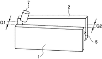
表1に示す試作ワイヤを用いて、MAG溶接による横向重ねすみ肉継手溶接で耐ギャップ性試験を行い、架橋可能なギャップ幅を調査した。試験体は、表2に示す化学成分、板厚1.6mm、溶接長500mmの980MPa級の高強度薄鋼板を使用した。耐ギャップ性試験は、図2に示すように前板1と後板2の間にスペーサ5を挟み、試験片長さ500mmの継手を形成した。この時、ギャップG1=1mmからG2=3mmへと広がるようにして溶接を行った。溶接のスタートはギャップG1=1mm側から表3に示すMAG溶接条件で行い、溶接金属が架橋できなくなるところまで溶接を実施した。なお、溶接は図3に示すように、前板1と後板2側の角を狙い位置にし、溶接トーチ7の角度θは30°として溶接した。この時の溶接可能なギャップを測定し、溶接可能なギャップが2.5mm以上を良好とした。またアーク状態、スパッタ発生量、スラグ生成量、溶融金属垂れの有無、ビード外観を調査した。さらに、溶接終了後マクロ試験片を溶接開始から200mmより採取しJISZ2244に準拠してビッカース硬さを測定し、10点の平均値が250〜400Hvを良好とした。それらの結果を表4にまとめて示す。
Using the prototype wires shown in Table 1, a gap resistance test was performed by transverse lap fillet joint welding by MAG welding, and a gap width capable of being bridged was investigated. As the test body, a 980 MPa class high-strength thin steel plate having a chemical composition shown in Table 2, a plate thickness of 1.6 mm, and a welding length of 500 mm was used. In the gap resistance test, as shown in FIG. 2, a
表1及び表4中の試験No.1〜No.8は本発明例、試験No.9〜No.16は比較例である。本発明例である試験No.1〜No.8は、ワイヤ記号W1〜W8が本発明で規定した各成分範囲内であるので、MAG溶接による横向重ねすみ肉継手溶接のアークが安定して、スパッタ発生量及びスラグ生成量が少なく、溶融金属の粘性及び表面張力が適正で溶融金属垂れが無く、溶接可能ギャップが広く、良好なビード外観が得られると共に溶接金属のビッカース硬さも適正であり、極めて満足な結果であった Test No. in Tables 1 and 4 1 to No. No. 8 is an example of the present invention, test No. 9-No. Reference numeral 16 is a comparative example. Test No. which is an example of the present invention. 1 to No. No. 8 shows that the wire symbols W1 to W8 are within the respective component ranges defined in the present invention, so that the arc of the transverse lap fillet joint welding by MAG welding is stable, the spatter generation amount and the slag generation amount are small, and the molten metal The viscosity and surface tension of the alloy were appropriate, there was no dripping of the molten metal, the weldable gap was wide, a good bead appearance was obtained, and the Vickers hardness of the weld metal was also appropriate.
なお、試験No.7は、ワイヤ記号W7のAlとTiの1種または2種の合計が多いので、スラグ生成量がやや多く、ビード外観がやや不良であったが、他は良好であり実用上問題にならない結果であった。 In addition, the test No. In No. 7, since the sum of one or two of Al and Ti of the wire symbol W7 was large, the amount of slag generated was slightly large, and the bead appearance was slightly poor, but the others were good and did not pose a practical problem. Met.
比較例中試験No.9は、ワイヤ記号W9のCが少ないので、アークが不安定となりスパッタ発生量も多かった。また、溶融金属の垂れが生じ、ビード外観が不良であった。 Test No. in the comparative example. In No. 9, since C in the wire symbol W9 was small, the arc became unstable and the amount of spatter generated was large. Further, the molten metal dripped, and the bead appearance was poor.
試験No.10は、ワイヤ記号W10のCが多いので、スパッタ発生量が多く、溶融金属の垂れが生じ、ビード外観が不良であった。また溶接金属の硬さが高くクレータ割れも発生した。 Test No. Sample No. 10 had a large amount of C in the wire symbol W10, so a large amount of spatter was generated, dripping of the molten metal occurred, and the bead appearance was poor. In addition, the hardness of the weld metal was high and crater cracks occurred.
試験No.11は、ワイヤ記号11のSiが少ないので、溶融金属の垂れが生じ、溶接可能ギャップが狭く、ビード外観が不良であった。 Test No. In No. 11, since the Si of the wire symbol 11 was small, the molten metal sagged, the weldable gap was narrow, and the bead appearance was poor.
試験No.12は、ワイヤ記号12のSiが多いので、ハンピングビードとなり、スパッタ発生量も多かった。また、スラグの生成量が多くビード外観が不良であった。 Test No. In No. 12, a large amount of Si of the wire symbol 12 resulted in a humping bead and a large amount of spatter. In addition, the amount of slag generated was large, and the bead appearance was poor.
試験No.13は、ワイヤ記号13のMnが少ないので、溶融金属の垂れが生じ、溶接可能ギャップが狭かった。 Test No. In No. 13, since the Mn of the wire symbol 13 was small, the molten metal sagged, and the weldable gap was narrow.
試験No.14は、ワイヤ記号W14のMnが多いので、スパッタ発生量が多かった。 Test No. In No. 14, since the Mn of the wire symbol W14 was large, the amount of spatter generated was large.
試験No.15は、ワイヤ記号W15のMoが少ないので、溶接金属の硬さが低く、スパッタ発生量も多かった。また、AlとTiの1種または2種の合計が多いので、スラグの生成量が多くビード外観が不良であった。 Test No. In No. 15, since the Mo of the wire symbol W15 was small, the hardness of the weld metal was low and the amount of spatter generated was large. Further, since one or two kinds of Al and Ti were large in total, the amount of slag generated was large and the bead appearance was poor.
試験No.16は、ワイヤ記号W16のMoが多いので、溶接金属の硬さが高く、クレータ割れも生じた。またスパッタ発生量も多かった。 Test No. In No. 16, since the Mo content of the wire symbol W16 was large, the hardness of the weld metal was high and crater cracking also occurred. Also, the amount of spatter generated was large.
表1に示す試作ワイヤを用いて、パルスMAG溶接による横向重ねすみ肉継手溶接のビード形状試験を行った。試験体は、実施例1と同一の試験体を使用した。溶接は、表3と表5に示す各パルスMAG溶接条件で実施例1と同一の溶接及び評価を行った。 Using the prototype wires shown in Table 1, a bead shape test of horizontal lap fillet joint welding by pulse MAG welding was performed. As the test body, the same test body as in Example 1 was used. For welding, the same welding and evaluation as in Example 1 were performed under the pulse MAG welding conditions shown in Tables 3 and 5.
表5中の試験No.17〜No.22は本発明例、試験No.23〜No.28は比較例である。本発明例である試験No.17〜No.22は、ワイヤ記号W1〜W6が本発明で規定した各成分範囲内で、パルスMAG溶接条件が適正であるので、パルスMAG溶接による横向重ね継手溶接のアークが安定して、スパッタ発生量及びスラグ生成量が少なく、溶融金属の粘性及び表面張力が適正で溶融金属垂れが無く、溶接可能ギャップが広く、良好なビード外観が得られると共に溶接金属のビッカース硬さも適正であり、極めて満足な結果であった Test No. in Table 5 17-No. 22 is an example of the present invention, test No. 22; 23-No. 28 is a comparative example. Test No. which is an example of the present invention. 17-No. 22 indicates that the pulse MAG welding conditions are appropriate within the respective component ranges defined by the wire symbols W1 to W6, so that the arc of the horizontal lap joint welding by the pulse MAG welding is stable, and the amount of spatter generation and slag The amount of generation is small, the molten metal viscosity and surface tension are appropriate, there is no molten metal dripping, the weldable gap is wide, a good bead appearance is obtained, and the Vickers hardness of the weld metal is also appropriate, with extremely satisfactory results. there were
比較例中の試験記号No.23は、ワイヤ記号W15のMoが少ないので、溶接金属の硬さが低く、スパッタ発生量も多かった。また、AlとTiの1種または2種の合計が多いので、スラグの生成量が多くビード外観が不良であった。また、パルスベース電流Ibが低いので、アークが不安定であった。 Test symbol No. in the comparative example. In No. 23, since Mo in the wire symbol W15 was small, the hardness of the weld metal was low and the amount of spatter generated was large. Further, since one or two kinds of Al and Ti were large in total, the amount of slag generated was large and the bead appearance was poor. Further, the arc was unstable because the pulse base current Ib was low.
試験記号No.24は、ワイヤ記号W16のMoが多いので、溶接金属の硬さが高く、クレータ割れも生じた。またスパッタ発生量も多かった。さらに、パルスピーク電流Ipが高いので、溶接開始近傍で溶融金属垂れが生じた。 Test code No. In No. 24, since the Mo content of the wire symbol W16 was large, the hardness of the weld metal was high and crater cracks also occurred. Also, the amount of spatter generated was large. Furthermore, since the pulse peak current Ip was high, molten metal dripping occurred near the start of welding.
試験記号No.25は、ワイヤ記号W14のMnが多いので、スパッタ発生量が多かった。また、パルスピーク電流Ipが低いので、アークが不安定で、ビード幅が狭くなり溶接可能ギャップが狭かった。 Test code No. In No. 25, since the Mn of the wire symbol W14 was large, the amount of spatter generated was large. Further, since the pulse peak current Ip was low, the arc was unstable, the bead width was narrowed, and the weldable gap was narrow.
試験No.26は、ワイヤ記号11のSiが少ないので、溶融金属の垂れが生じ、ビード外観が不良で、溶接可能ギャップが狭かった。さらに、パルスベース電流Ibが高いので、アークが不安定となりスパッタ発生量も多かった。 Test No. In No. 26, since the Si of the wire symbol 11 was small, the molten metal sagged, the bead appearance was poor, and the weldable gap was narrow. Furthermore, since the pulse base current Ib was high, the arc became unstable and the amount of spatter generated was large.
試験No.27は、ワイヤ記号W3が本発明で規定した各成分範囲内であるが、パルスピーク電流Ipとピーク時間Tpの積Ip×Tpが低いので、溶融金属の垂れが生じ、ビード幅が狭くなり溶接可能ギャップが狭かった。 Test No. Reference numeral 27 indicates that the wire symbol W3 is within each component range defined in the present invention, but since the product Ip × Tp of the pulse peak current Ip and the peak time Tp is low, the molten metal sags, the bead width becomes narrow, and the welding is performed. Possible gap was narrow.
試験No.28は、ワイヤ記号W8が本発明で規定した各成分範囲内であるが、パルスピーク電流Ipとピーク時間Tpの積Ip×Tpが高いので、スパッタ発生量が多かった。さらに、溶融金属垂れが生じ、ビード幅が狭くなり溶接可能ギャップが狭かった。 Test No. 28 is within the range of each component defined by the present invention for the wire symbol W8, but since the product Ip × Tp of the pulse peak current Ip and the peak time Tp is high, the spatter generation amount was large. Further, the molten metal sagged, the bead width was narrowed, and the weldable gap was narrow.
1 前板
2 後板
3 溶接金属
4 アンダーカット
5 スペーサ
6、61、62 ワイヤ狙い位置
7 溶接トーチ
W ビード幅
θ トーチ角度
G ギャップ
Reference Signs List 1
Claims (3)
ワイヤ全質量に対する質量%で
C:0.20超〜0.50%、
Si:0.05〜0.20%、
Mn:1.5〜2.5%、
Mo:0.3〜0.6%を含有し、
P:0.03%以下、
S:0.03%以下であり、
残部はFe及び不可避不純物からなることを特徴とする高強度薄鋼板のMAG溶接用ワイヤ。 In a MAG welding wire of a high strength thin steel plate having a thickness of 1.2 to 3.2 mm,
% By mass based on the total mass of the wire C: more than 0.20 to 0.50%,
Si: 0.05 to 0.20%,
Mn: 1.5 to 2.5%,
Mo: containing 0.3 to 0.6%,
P: 0.03% or less,
S: not more than 0.03%,
The remainder is composed of Fe and unavoidable impurities, and is a wire for MAG welding a high-strength thin steel plate.
AlとTiの1種又は2種以上の合計:0.15%以下をさらに含有することを特徴とする請求項1記載の高強度薄鋼板のMAG溶接用ワイヤ。 In mass% based on the total mass of the wire,
The MAG welding wire for a high-strength steel sheet according to claim 1, further comprising 0.15% or less of one or more of Al and Ti.
パルスピーク電流(Ip):400〜600A、
パルスベース電流(Ib):30〜80Aとし、
前記パルスピーク電流(Ip)とパルスピーク時間(Tp)が下記式(1)を満足するパルスを付加して溶接することを特徴とするパルスMAG溶接方法。
400≦Ip(A)×Tp(msec) ≦800・・・・・(1) A pulse MAG welding method using a MAG welding wire for a high-strength thin steel sheet according to claim 1 or 2,
Pulse peak current (Ip): 400 to 600 A,
Pulse base current (Ib): 30 to 80 A,
A pulse MAG welding method, characterized in that a pulse having a pulse peak current (Ip) and a pulse peak time (Tp) that satisfies the following equation (1) is added and welded.
400 ≦ Ip (A) × Tp (msec) ≦ 800 (1)
Priority Applications (1)
| Application Number | Priority Date | Filing Date | Title |
|---|---|---|---|
| JP2017001306A JP6676552B2 (en) | 2017-01-06 | 2017-01-06 | MAG welding wire for high strength thin steel sheet and pulse MAG welding method using the same |
Applications Claiming Priority (1)
| Application Number | Priority Date | Filing Date | Title |
|---|---|---|---|
| JP2017001306A JP6676552B2 (en) | 2017-01-06 | 2017-01-06 | MAG welding wire for high strength thin steel sheet and pulse MAG welding method using the same |
Publications (2)
| Publication Number | Publication Date |
|---|---|
| JP2018111101A JP2018111101A (en) | 2018-07-19 |
| JP6676552B2 true JP6676552B2 (en) | 2020-04-08 |
Family
ID=62910734
Family Applications (1)
| Application Number | Title | Priority Date | Filing Date |
|---|---|---|---|
| JP2017001306A Active JP6676552B2 (en) | 2017-01-06 | 2017-01-06 | MAG welding wire for high strength thin steel sheet and pulse MAG welding method using the same |
Country Status (1)
| Country | Link |
|---|---|
| JP (1) | JP6676552B2 (en) |
Families Citing this family (1)
| Publication number | Priority date | Publication date | Assignee | Title |
|---|---|---|---|---|
| JP7832450B2 (en) * | 2021-12-14 | 2026-03-18 | 日本製鉄株式会社 | Solid wire for welding aluminum-plated steel sheets, and method for manufacturing welded joints. |
Family Cites Families (3)
| Publication number | Priority date | Publication date | Assignee | Title |
|---|---|---|---|---|
| JPH07232294A (en) * | 1994-02-23 | 1995-09-05 | Sumitomo Metal Ind Ltd | Welding wire for galvanized steel sheet and welding method |
| JP2801147B2 (en) * | 1994-07-08 | 1998-09-21 | 株式会社神戸製鋼所 | Welding method |
| JP2007301623A (en) * | 2006-05-15 | 2007-11-22 | Nippon Steel & Sumikin Welding Co Ltd | High-speed gas shielded arc welding method for transverse lap joints of thin steel sheets |
-
2017
- 2017-01-06 JP JP2017001306A patent/JP6676552B2/en active Active
Also Published As
| Publication number | Publication date |
|---|---|
| JP2018111101A (en) | 2018-07-19 |
Similar Documents
| Publication | Publication Date | Title |
|---|---|---|
| CN100509260C (en) | Solid core soldering wire | |
| JP2009255125A (en) | PURE Ar GAS SHIELDED WELDING MIG FLUX-CORED WIRE AND MIG ARC WELDING METHOD | |
| JP4755576B2 (en) | Gas shield arc welding method | |
| US9102013B2 (en) | Flux-cored welding wire for carbon steel and process for arc welding | |
| JP2008290116A (en) | Fillet welded joint and welding method | |
| WO2022050014A1 (en) | Arc welding method | |
| JP4857015B2 (en) | Gas shielded arc welding flux cored wire and welding method | |
| JP5104037B2 (en) | Fillet welding method and fillet welded joint | |
| JP6800770B2 (en) | Pulse MAG welding method for thin steel sheets | |
| JPWO2021125280A1 (en) | Steel wire for gas shielded arc welding, gas shielded arc welding method, and manufacturing method of gas shielded arc welded joint | |
| JP6683635B2 (en) | Pulse MAG welding method for high strength thin steel sheet | |
| JP7060159B2 (en) | MIG welding method | |
| JP5925703B2 (en) | Solid wire for gas shielded arc welding of thin steel sheet | |
| WO2017098692A1 (en) | Vertical narrow gap gas shielded arc welding method | |
| JP2007301623A (en) | High-speed gas shielded arc welding method for transverse lap joints of thin steel sheets | |
| JP6676552B2 (en) | MAG welding wire for high strength thin steel sheet and pulse MAG welding method using the same | |
| WO2022230905A1 (en) | Arc-welded joint and arc-welding method | |
| JP5236337B2 (en) | Solid wire for pulse MAG welding of thin steel sheet | |
| JP5037369B2 (en) | Solid wire for pulse MAG welding | |
| JP6676553B2 (en) | MAG welding wire for high strength thin steel sheet and pulse MAG welding method using the same | |
| JP6119948B1 (en) | Vertical narrow groove gas shielded arc welding method | |
| JP5086881B2 (en) | High-speed gas shield arc welding method for thin steel sheet | |
| JP4930048B2 (en) | Plasma arc hybrid welding method to improve joint fatigue strength of lap fillet welded joint | |
| JP6709177B2 (en) | Pulse MAG welding method for thin steel sheet | |
| JP5080748B2 (en) | Tandem arc welding method |
Legal Events
| Date | Code | Title | Description |
|---|---|---|---|
| A621 | Written request for application examination |
Free format text: JAPANESE INTERMEDIATE CODE: A621 Effective date: 20190606 |
|
| A977 | Report on retrieval |
Free format text: JAPANESE INTERMEDIATE CODE: A971007 Effective date: 20200212 |
|
| TRDD | Decision of grant or rejection written | ||
| A01 | Written decision to grant a patent or to grant a registration (utility model) |
Free format text: JAPANESE INTERMEDIATE CODE: A01 Effective date: 20200310 |
|
| A61 | First payment of annual fees (during grant procedure) |
Free format text: JAPANESE INTERMEDIATE CODE: A61 Effective date: 20200312 |
|
| R150 | Certificate of patent or registration of utility model |
Ref document number: 6676552 Country of ref document: JP Free format text: JAPANESE INTERMEDIATE CODE: R150 |
|
| R250 | Receipt of annual fees |
Free format text: JAPANESE INTERMEDIATE CODE: R250 |
|
| R250 | Receipt of annual fees |
Free format text: JAPANESE INTERMEDIATE CODE: R250 |
|
| R250 | Receipt of annual fees |
Free format text: JAPANESE INTERMEDIATE CODE: R250 |
|
| R250 | Receipt of annual fees |
Free format text: JAPANESE INTERMEDIATE CODE: R250 |