JP6673323B2 - Vehicle air conditioning controller - Google Patents
Vehicle air conditioning controller Download PDFInfo
- Publication number
- JP6673323B2 JP6673323B2 JP2017245174A JP2017245174A JP6673323B2 JP 6673323 B2 JP6673323 B2 JP 6673323B2 JP 2017245174 A JP2017245174 A JP 2017245174A JP 2017245174 A JP2017245174 A JP 2017245174A JP 6673323 B2 JP6673323 B2 JP 6673323B2
- Authority
- JP
- Japan
- Prior art keywords
- vehicle
- air
- condenser
- shut
- inflow
- Prior art date
- Legal status (The legal status is an assumption and is not a legal conclusion. Google has not performed a legal analysis and makes no representation as to the accuracy of the status listed.)
- Active
Links
Images


Classifications
-
- B—PERFORMING OPERATIONS; TRANSPORTING
- B60—VEHICLES IN GENERAL
- B60H—ARRANGEMENTS OF HEATING, COOLING, VENTILATING OR OTHER AIR-TREATING DEVICES SPECIALLY ADAPTED FOR PASSENGER OR GOODS SPACES OF VEHICLES
- B60H1/00—Heating, cooling or ventilating [HVAC] devices
- B60H1/32—Cooling devices
- B60H1/3204—Cooling devices using compression
- B60H1/3205—Control means therefor
- B60H1/3211—Control means therefor for increasing the efficiency of a vehicle refrigeration cycle
-
- B—PERFORMING OPERATIONS; TRANSPORTING
- B60—VEHICLES IN GENERAL
- B60H—ARRANGEMENTS OF HEATING, COOLING, VENTILATING OR OTHER AIR-TREATING DEVICES SPECIALLY ADAPTED FOR PASSENGER OR GOODS SPACES OF VEHICLES
- B60H1/00—Heating, cooling or ventilating [HVAC] devices
- B60H1/00642—Control systems or circuits; Control members or indication devices for heating, cooling or ventilating devices
- B60H1/00735—Control systems or circuits characterised by their input, i.e. by the detection, measurement or calculation of particular conditions, e.g. signal treatment, dynamic models
- B60H1/00764—Control systems or circuits characterised by their input, i.e. by the detection, measurement or calculation of particular conditions, e.g. signal treatment, dynamic models the input being a vehicle driving condition, e.g. speed
-
- B—PERFORMING OPERATIONS; TRANSPORTING
- B60—VEHICLES IN GENERAL
- B60H—ARRANGEMENTS OF HEATING, COOLING, VENTILATING OR OTHER AIR-TREATING DEVICES SPECIALLY ADAPTED FOR PASSENGER OR GOODS SPACES OF VEHICLES
- B60H1/00—Heating, cooling or ventilating [HVAC] devices
- B60H1/32—Cooling devices
- B60H1/3204—Cooling devices using compression
- B60H1/3227—Cooling devices using compression characterised by the arrangement or the type of heat exchanger, e.g. condenser, evaporator
-
- B—PERFORMING OPERATIONS; TRANSPORTING
- B60—VEHICLES IN GENERAL
- B60K—ARRANGEMENT OR MOUNTING OF PROPULSION UNITS OR OF TRANSMISSIONS IN VEHICLES; ARRANGEMENT OR MOUNTING OF PLURAL DIVERSE PRIME-MOVERS IN VEHICLES; AUXILIARY DRIVES FOR VEHICLES; INSTRUMENTATION OR DASHBOARDS FOR VEHICLES; ARRANGEMENTS IN CONNECTION WITH COOLING, AIR INTAKE, GAS EXHAUST OR FUEL SUPPLY OF PROPULSION UNITS IN VEHICLES
- B60K11/00—Arrangement in connection with cooling of propulsion units
- B60K11/02—Arrangement in connection with cooling of propulsion units with liquid cooling
- B60K11/04—Arrangement or mounting of radiators, radiator shutters, or radiator blinds
-
- B—PERFORMING OPERATIONS; TRANSPORTING
- B60—VEHICLES IN GENERAL
- B60H—ARRANGEMENTS OF HEATING, COOLING, VENTILATING OR OTHER AIR-TREATING DEVICES SPECIALLY ADAPTED FOR PASSENGER OR GOODS SPACES OF VEHICLES
- B60H1/00—Heating, cooling or ventilating [HVAC] devices
- B60H1/00642—Control systems or circuits; Control members or indication devices for heating, cooling or ventilating devices
- B60H1/00814—Control systems or circuits characterised by their output, for controlling particular components of the heating, cooling or ventilating installation
- B60H1/00821—Control systems or circuits characterised by their output, for controlling particular components of the heating, cooling or ventilating installation the components being ventilating, air admitting or air distributing devices
- B60H1/00828—Ventilators, e.g. speed control
-
- B—PERFORMING OPERATIONS; TRANSPORTING
- B60—VEHICLES IN GENERAL
- B60H—ARRANGEMENTS OF HEATING, COOLING, VENTILATING OR OTHER AIR-TREATING DEVICES SPECIALLY ADAPTED FOR PASSENGER OR GOODS SPACES OF VEHICLES
- B60H1/00—Heating, cooling or ventilating [HVAC] devices
- B60H1/32—Cooling devices
- B60H2001/3236—Cooling devices information from a variable is obtained
- B60H2001/3239—Cooling devices information from a variable is obtained related to flow
- B60H2001/3241—Cooling devices information from a variable is obtained related to flow of air
-
- B—PERFORMING OPERATIONS; TRANSPORTING
- B60—VEHICLES IN GENERAL
- B60H—ARRANGEMENTS OF HEATING, COOLING, VENTILATING OR OTHER AIR-TREATING DEVICES SPECIALLY ADAPTED FOR PASSENGER OR GOODS SPACES OF VEHICLES
- B60H1/00—Heating, cooling or ventilating [HVAC] devices
- B60H1/32—Cooling devices
- B60H2001/3236—Cooling devices information from a variable is obtained
- B60H2001/3248—Cooling devices information from a variable is obtained related to pressure
- B60H2001/3251—Cooling devices information from a variable is obtained related to pressure of the refrigerant at a condensing unit
-
- B—PERFORMING OPERATIONS; TRANSPORTING
- B60—VEHICLES IN GENERAL
- B60H—ARRANGEMENTS OF HEATING, COOLING, VENTILATING OR OTHER AIR-TREATING DEVICES SPECIALLY ADAPTED FOR PASSENGER OR GOODS SPACES OF VEHICLES
- B60H1/00—Heating, cooling or ventilating [HVAC] devices
- B60H1/32—Cooling devices
- B60H2001/3269—Cooling devices output of a control signal
- B60H2001/3276—Cooling devices output of a control signal related to a condensing unit
- B60H2001/3277—Cooling devices output of a control signal related to a condensing unit to control the air flow
Landscapes
- Engineering & Computer Science (AREA)
- Mechanical Engineering (AREA)
- Physics & Mathematics (AREA)
- Thermal Sciences (AREA)
- Chemical & Material Sciences (AREA)
- Combustion & Propulsion (AREA)
- Transportation (AREA)
- Air-Conditioning For Vehicles (AREA)
Description
本発明は、車両用空調制御装置に関する。 The present invention relates to a vehicle air conditioning control device.
従来より、車両の隊列走行時において前車の後方を走行する自車を減速させて前車との車間距離を広げることにより、自車内に吹き込まれる流入空気流量を増大させるように構成された車両走行制御装置が、例えば特許文献1で提案されている。 2. Description of the Related Art Conventionally, a vehicle configured to increase the flow rate of inflow air blown into a host vehicle by decelerating the host vehicle traveling behind the preceding vehicle during the platooning of the vehicle to increase the inter-vehicle distance with the preceding vehicle. A travel control device has been proposed in, for example, Patent Document 1.
しかしながら、上記従来の技術では、車両の隊列走行時に前車と自車との車間距離が広くなるので、自車が走行中に受ける空気抵抗が大きくなる。このため、隊列走行時に自車の燃費が悪化してしまう。 However, in the above-described conventional technology, the inter-vehicle distance between the preceding vehicle and the own vehicle during the platooning of the vehicles increases, so that the air resistance received by the own vehicle during running increases. For this reason, the fuel efficiency of the own vehicle deteriorates during platooning.
一方、自動運転により、前車との車間距離が狭い状態での隊列走行が可能になる。これにより、自車は前車のスリップストリームに入るため、自車が走行中に受ける空気抵抗が低下し、自車の燃費の悪化が抑制される。 On the other hand, the automatic driving enables the platooning in a state where the distance between the vehicle and the preceding vehicle is short. As a result, the own vehicle enters the slip stream of the preceding vehicle, so that the air resistance that the own vehicle receives while traveling is reduced, and the deterioration of the fuel efficiency of the own vehicle is suppressed.
しかし、自車は前車のスリップストリームに入るため、隊列走行時の自車への流入空気流量が低下してしまう。このため、コンデンサに風が当たりにくくなり、空調冷却に必要な風量を確保できなくなり、高圧上昇により冷凍サイクルが悪化する。これを解消するために空調動力が増大してしまい、その結果、自車の燃費が悪化してしまうという問題がある。 However, since the own vehicle enters the slip stream of the preceding vehicle, the flow rate of air flowing into the own vehicle during platooning decreases. For this reason, it is difficult for the air to hit the condenser, and it becomes impossible to secure the air volume required for air-conditioning cooling, and the refrigeration cycle is deteriorated by the high pressure rise. In order to solve this, there is a problem that the air-conditioning power increases, and as a result, the fuel efficiency of the own vehicle deteriorates.
本発明は上記点に鑑み、隊列走行時に前車に対して車間距離を詰めた状態で、自車のコンデンサへの空気の取り込みを確保することができる車両用空調制御装置を提供することを目的とする。 In view of the above, it is an object of the present invention to provide a vehicle air-conditioning control device that can secure the intake of air into a condenser of a vehicle in a state in which the distance between vehicles in front of the vehicle is reduced during platooning. And
上記目的を達成するため、請求項1、2に記載の発明では、車両用空調制御装置は、自車(100)が自動運転中であって、前車(200)に追従する隊列走行時に、前車のスリップストリームに入っているか否かを判定する判定部(12a)を備えている。 In order to achieve the above object, in the invention according to claims 1 and 2 , the vehicle air-conditioning control device is configured such that, when the vehicle (100) is in automatic operation and the vehicle runs in a platoon following the preceding vehicle (200), A determination unit (12a) for determining whether or not the vehicle is in the slip stream of the preceding vehicle is provided.
車両用空調制御装置は、判定部によって自車が前車のスリップストリームに入っていると判定された場合、自車の空調用のコンデンサ(13)に流入する空気量を増大させる制御を行う制御部(12b)を備えている。
さらに、請求項1に記載の発明では、自車の前方からコンデンサの空気流入面(14)への空気の流入を許可または遮断する第1シャット機構(23)と、自車の地面(300)側からコンデンサの空気流入面への空気の流入を許可または遮断する第2シャット機構(22)と、が自車に設けられ、自車が前車のスリップストリームに入っていない場合には第1シャット機構が開口し、第2シャット機構が閉口している。制御部は、第1シャット機構を閉口して第1シャット機構を介して空気流入面への空気の流入を遮断すると共に、第2シャット機構を開口させる制御を行って第2シャット機構を介して空気流入面への空気の流入を許可することにより、地面側からコンデンサに流入する空気量を増大させる。
さらに、請求項2に記載の発明では、自車の前方からコンデンサの空気流入面(14)への空気の流入を許可または遮断する第1シャット機構(23)と、自車の側面(101)側からコンデンサの空気流入面への空気の流入を許可または遮断する第2シャット機構(24)と、が自車に設けられ、自車が前車のスリップストリームに入っていない場合には第1シャット機構が開口し、第2シャット機構が閉口している。制御部は、第1シャット機構を閉口して第1シャット機構を介して空気流入面への空気の流入を遮断すると共に、第2シャット機構を開口させる制御を行って第2シャット機構を介して空気流入面への空気の流入を許可することにより、自車の側面側からコンデンサに流入する空気量を増大させる。
When the determination unit determines that the vehicle is in the slipstream of the preceding vehicle, the vehicle air conditioning control device performs control for increasing the amount of air flowing into the air conditioning condenser (13) of the vehicle. (12b).
Furthermore, according to the first aspect of the present invention, the first shut-off mechanism (23) for permitting or blocking the inflow of air from the front of the own vehicle to the air inlet surface (14) of the condenser, and the ground (300) of the own vehicle. And a second shut-off mechanism (22) for permitting or blocking the inflow of air from the side to the air inflow surface of the condenser, and a first shut-off mechanism (22) provided when the own vehicle is not in the slip stream of the preceding vehicle. The shut mechanism is open, and the second shut mechanism is closed. The control unit closes the first shut-off mechanism to shut off the inflow of air to the air inflow surface via the first shut-off mechanism, and controls the second shut-off mechanism to open, and controls the second shut-off mechanism via the second shut-off mechanism. By allowing the air to flow into the air inflow surface, the amount of air flowing into the condenser from the ground side is increased.
Further, in the invention according to claim 2, the first shut-off mechanism (23) for permitting or blocking the inflow of air from the front of the own vehicle to the air inlet surface (14) of the condenser, and the side surface (101) of the own vehicle. And a second shut-off mechanism (24) for permitting or shutting off the inflow of air from the side to the air inlet surface of the condenser. The shut mechanism is open, and the second shut mechanism is closed. The control unit closes the first shut-off mechanism to shut off the inflow of air to the air inflow surface via the first shut-off mechanism, and controls the second shut-off mechanism to open, thereby performing control via the second shut-off mechanism. By allowing the air to flow into the air inflow surface, the amount of air flowing into the condenser from the side surface of the vehicle is increased.
これによると、自動運転中であって、隊列走行時に、前車のスリップストリームに入っている状況でも、制御部によってコンデンサに流入する空気量を増大させることができる。したがって、隊列走行時に前車に対して車間距離を詰めた状態で、自車のコンデンサへの空気の取り込みを確保することができる。 According to this, it is possible to increase the amount of air flowing into the condenser by the control unit even during the automatic driving and in the slipstream of the preceding vehicle during the platooning. Therefore, it is possible to ensure that air is taken into the condenser of the own vehicle while the inter-vehicle distance is shorter than that of the preceding vehicle during platooning.
なお、この欄及び特許請求の範囲で記載した各手段の括弧内の符号は、後述する実施形態に記載の具体的手段との対応関係を示すものである。 In addition, reference numerals in parentheses of each means described in this column and in the claims indicate the correspondence with specific means described in the embodiments described later.
以下、各実施形態について図に基づいて説明する。なお、以下の各実施形態相互において、互いに同一もしくは均等である部分には、図中、同一符号を付してある。 Hereinafter, each embodiment will be described with reference to the drawings. In the following embodiments, parts that are the same or equivalent are denoted by the same reference numerals in the drawings.
(第1実施形態)
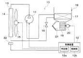
以下、第1実施形態について図を参照して説明する。図1に示された空調装置10は、車両に搭載されると共に、冷凍サイクルによって空調対象空間である車室内へ送風される車室内送風空気を冷却する空調制御を行うものである。
(1st Embodiment)
Hereinafter, the first embodiment will be described with reference to the drawings. The
まず、コンプレッサ11は、エンジンルーム内に配置されており、冷媒を吸入・圧縮して吐出するものである。図示しないが、コンプレッサ11はハウジングにインバータが一体化された構成になっている。ハウジングは、冷媒を吸入する冷媒吸入口と、冷媒吸入口から吸入した冷媒を圧縮して吐出する冷媒吐出口と、を有している。また、ハウジングは、図示しない電動モータと、冷媒を圧縮する圧縮機構と、を収容している。
First, the
電動モータは、後述する制御装置12から出力される制御信号によって、その作動が制御される。具体的には、電動モータは回転数が制御される。圧縮機構は冷媒を圧縮するものであり、電動モータによって駆動される。圧縮機構は、例えばスクロール型圧縮機構である。そして、制御装置12からインバータへ目標回転数を指示し、インバータが電動モータの回転数を制御することによって、圧縮機構の冷媒吐出能力が変更される。インバータは、制御装置12から入力される制御信号に従ってパワー素子を駆動することにより電動モータを回転させる。
The operation of the electric motor is controlled by a control signal output from a
コンプレッサ11の冷媒吐出口は、空調用のコンデンサ13の冷媒入口側に接続されている。コンデンサ13は、内部を流通する高温高圧の冷媒と当該コンデンサ13を通過する外気とを熱交換させるものであり、エンジンルーム内に配置されている。すなわち、コンデンサ13は、冷房運転時に高温高圧冷媒を放熱させる放熱器として機能する熱交換器である。本実施形態では、コンデンサ13の空気流入面14は地面に対してほぼ垂直に配置されている。
A refrigerant discharge port of the
コンデンサ13の通風経路上には電動ファン15が配置されている。電動ファン15はコンデンサ13に対して車両後方側に配置されている。電動ファン15は、制御装置12から出力される制御電圧によって稼働率、すなわち回転数が制御される電動式送風機である。つまり、電動ファン15は制御装置12によって送風空気量が制御される。単独走行では、車速が一定以上になると電動ファン15を動作させなくてもコンデンサ13に対して空調冷却に必要な風量を確保できるため、電動ファン15は、車速が一定以上の場合、動作が停止するように制御される。
An
コンデンサ13の出口側は、機械式の膨張弁16に接続されている。この膨張弁16は、冷房運転時にコンデンサ13から流出した冷媒を減圧膨張させる減圧手段である。膨張弁16の出口側には、エバポレータ17の冷媒入口側が接続されている。
The outlet side of the
エバポレータ17は、室内空調ユニット18のケーシング19内に配置されている。エバポレータ17は、その内部を流通する冷媒と車室内送風空気とを熱交換させ、車室内送風空気を冷却する冷却用熱交換器である。エバポレータ17の冷媒出口側には、コンプレッサ11の吸入側が接続されている。
The
室内空調ユニット18は、車室内最前部の計器盤の内側に配置されている。また、室内空調ユニット18は、その外殻を形成するケーシング19内に送風機20やエバポレータ17等を収容している。ケーシング19内の車室内送風空気流れ最上流側には、内気と外気とを切替導入する内外気切替装置21が配置されている。内気は、車室内空気である。
The indoor air-
内外気切替装置21は、ケーシング19内に内気を導入させる内気導入口及び外気を導入させる外気導入口の開口面積を、内外気切替ドアによって連続的に調整する内外気切替手段である。これにより、内外気切替装置21は、内気と外気との導入割合を連続的に変化させて吸込口モードを切り替える。
The inside / outside
内外気切替装置21の空気流れ下流側には、内外気切替装置21を介して吸入された空気を車室内へ向けて送風する送風機20が配置されている。この送風機20は、遠心多翼ファンを電動モータにて駆動する電動送風機である。送風機20は、制御装置12から出力される制御電圧によって回転数、すなわち送風量が制御される。送風機20は、例えばシロッコファンである。
On the downstream side of the air flow of the inside / outside
制御装置12は、自車の空調を制御する車両用空調制御装置である。制御装置12は、CPU、ROM及びRAM等を含む周知のマイクロコンピュータとその周辺回路から構成された電子制御装置(Electronic Control Unit;ECU)である。
The
制御装置12は、図示しない内気センサ、外気センサ、日射センサ、コンデンサ13の冷媒圧力を検出する高圧側圧力センサ等の空調制御用のセンサ群からセンサ信号を入力する。また、制御装置12には、車室内前部の計器盤付近に配置された図示しない操作パネルから各種空調操作スイッチの操作信号を入力する。
The
そして、制御装置12は、ROMに記憶された空調制御プログラムに従って各種演算、処理を行う。これにより、制御装置12は、コンプレッサ11のインバータ、電動ファン15、送風機20等の各種空調制御機器に制御信号を出力して各機器の作動を制御する。なお、制御装置12は、自動運転中に限らず空調制御において必要に応じて電動ファン15を動作させる。
Then, the
さらに、制御装置12は、自動運転中であって、隊列走行時に一定の条件を満たす場合、自車100のコンデンサ13に流入する空気量を増大させる制御を行う。このため、制御装置12は、自車が自動運転中であるか否かの判定、及び、隊列走行中であるかを判定する判定部12aと、判定部12aの判定結果に応じた制御を行う制御部12bと、を有している。
Further, the
判定部12aは、自車が自動運転中であって、前車に追従する隊列走行時に、前車のスリップストリームに入っているか否かを判定する。制御部12bは、判定部12aによって自車が前車のスリップストリームに入っていると判定された場合、自車の空調用のコンデンサ13に流入する空気量を増大させる制御を行う。
The
制御装置12は、自動運転及び隊列走行の判定を行うために、自動運転であることの情報、自車の車速、前車との車間距離、車車間通信による前車の車種や車速等の情報、カメラによって撮影された自車前方の画像分析による前車の情報等、走行中の様々な情報を取得する。前車の車種情報は、自車が前車のスリップストリームに入っているか否かを判定する材料として用いられる。以上が、本実施形態に係る空調装置10の全体構成である。
The
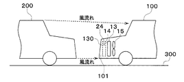
次に、自車が自動運転中であって、図2に示されるように自車100が前車200に追従する隊列走行時における制御装置12の電動ファン15に対する駆動制御処理について説明する。駆動制御処理は、判定部12a及び制御部12bによって実行される。
Next, a description will be given of a drive control process for the
隊列走行時では、前車200が自車100の前を走行するため、自車100に対する風流れが通常とは異なり、自車100が空気抵抗を受けにくくなる。言い換えると、自車100のフロント部分のグリル110からコンデンサ13に流入する空気量が減少する。なお、前車200が自動運転であるか否かは問わない。
During platooning, the
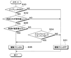
図3に示された駆動制御処理は、予め設定されたタイミングや条件に従って繰り返し実行される。まず、ステップS30では、コンプレッサ11がONしているか否かが判定される。すなわち、空調装置10によって冷房運転が行われているか否かが判定される。コンプレッサ11の動作は制御装置12によって把握されている。
The drive control process shown in FIG. 3 is repeatedly executed according to preset timings and conditions. First, in step S30, it is determined whether the
ステップS30にてコンプレッサ11がONしていないと判定された場合、ステップS31に進む。ステップS31では電動ファン15がOFFされ、あるいは電動ファン15のOFFが維持され、駆動制御処理は終了する。
If it is determined in step S30 that the
ステップS30にてコンプレッサ11がONであると判定された場合、ステップS32に進む。ステップS32では、コンデンサ13の冷媒圧力が規定値以上か否かが判定される。コンデンサ13の冷媒圧力が規定値以上ではない場合、冷房能力は低下していない。よって、ステップS31に進み、電動ファン15がOFFされ、駆動制御処理は終了する。 一方、ステップS32にて、コンデンサ13の冷媒圧力が規定値以上であると判定された場合、ステップS33に進む。ステップS33では車速が規定値以下であるか否かが判定される。車速が規定値以下ではない、すなわち車両が規定値を超える車速で走行している場合、ステップS34に進む。車速が規定値以下の場合、コンデンサ13に流入する空気量が少ないと考えられ、ステップS35に進む。
If it is determined in step S30 that the
ステップS34では、判定部12aによって、自車100が前車200のスリップストリームに入っているか否かが判定される。これは、自車100の車速、前車との車間距離、前車の車種等を基準に判定される。自車100が前車200のスリップストリームに入っていないと判定された場合、ステップS31に進み、電動ファン15がOFFされ、駆動制御処理は終了する。自車100が前車200のスリップストリームに入っていると判定された場合、ステップS35に進む。
In step S34, the
ステップS35では、制御部12bによって、電動ファン15がONされる。これにより、コンデンサ13の通風経路上に配置された電動ファン15が動作するので、グリル110からコンデンサ13に流入する空気量が増大する。これにより、空調冷却に必要な風量をコンデンサ13に流入させることができる。
In step S35, the
つまり、自動運転中であって隊列走行時に電動ファン15がONされる条件は、コンプレッサ11がONであり、コンデンサ13の冷媒圧力が規定値以上であり、車速が規定値以下である場合である。あるいは、コンプレッサ11がONであり、コンデンサ13の冷媒圧力が規定値以上であり、車速が規定値以下ではないが、自車100が前車200のスリップストリームに入っている場合である。こうして、駆動制御処理は終了し、繰り返される。
That is, the condition under which the
以上説明したように、本実施形態では、自動運転中であって、隊列走行時に、前車200のスリップストリームに入っている場合、制御部12bによって電動ファン15を強制的にONしている。これにより、コンデンサ13に流入する空気量を増大させることができる。したがって、隊列走行時に前車200に対して車間距離を詰めた状態で、自車100のコンデンサ13への空気の取り込みを確保することができる。
As described above, in the present embodiment, the
また、冷媒の高圧上昇を抑えることができるので、冷凍サイクルの悪化を抑制することができる。このため、空調動力の増大を抑制でき、ひいては自車100の燃費の悪化を解消することができる。
Further, since the increase in the high pressure of the refrigerant can be suppressed, deterioration of the refrigeration cycle can be suppressed. For this reason, the increase in the air-conditioning power can be suppressed, and the deterioration of the fuel efficiency of the
(第2実施形態)
本実施形態では、第1実施形態と異なる部分について説明する。図4に示されるように、自車100のコンデンサ13の地面側には地面側から空気流入面14への空気の流入を許可または遮断するシャット機構22が設けられている。シャット機構22の開閉は、制御部12bによって制御される。なお、自車100のフロント部分にはグリル110が開口している。
(2nd Embodiment)
In the present embodiment, portions different from the first embodiment will be described. As shown in FIG. 4, on the ground side of the
また、図5に示されるように、コンデンサ13は、空気流入面14が地面300側に向けられた状態で自車100に設けられている。シャット機構22は、例えば、閉状態であっても地面側のグリル120からコンデンサ13の空気流入面14に空調冷却に必要な風量が取り込まれるようになっている。シャット機構22が開状態になると、閉状態よりも空気流入面14に流入する空気量が増大する。なお、シャット機構22の開状態及び閉状態におけるコンデンサ13への流入空気量は適宜設計すれば良い。
As shown in FIG. 5, the
制御部12bは、自動運転中であって、隊列走行時に、上述のステップS34と同様に自車100が前車200のスリップストリームに入っていると判定した場合、シャット機構22を開口させる制御を行ってコンデンサ13の空気流入面14への空気の流入を許可する。これにより、電動ファン15をONさせなくても、地面300側からコンデンサ13に流入する空気量を増大させることができる。一方、自車100が前車200のスリップストリームから外れた場合、制御部12bはシャット機構22を閉口させる制御を行ってコンデンサ13への流入空気量を調整する。
If the
制御部12bは、少なくともスリップストリームの判定とシャット機構22の開閉制御を行うことになるが、第1実施形態で示された図3の駆動制御処理と組み合わせても良い。一つの変形例として、図3の駆動制御処理においてステップS35を「シャット機構22を開口させる」とし、ステップS31を「シャット機構22を閉口させる」とすることができる。
The
別の変形例として、図3の駆動制御処理においてステップS35を「電動ファン15をONすると共に、シャット機構22を開口させる」とし、ステップS31を「電動ファン15をOFFすると共に、シャット機構22を閉口させる」とすることができる。
As another modified example, in the drive control process of FIG. 3, step S35 is set to “turn on the
(第3実施形態)
本実施形態では、第1、第2実施形態と異なる部分について説明する。図6に示されるように、コンデンサ13は、空気流入面14が地面300に対して垂直になるように自車100のエンジンルーム内に配置されている。また、自車100には制御部12bによって開閉が制御される第1シャット機構23及び第2シャット機構22が設けられている。
(Third embodiment)
In the present embodiment, portions different from the first and second embodiments will be described. As shown in FIG. 6, the
第1シャット機構23は、車両前面に設けられたグリルシャッタである。第1シャット機構23は、自車100の前方からコンデンサ13への空気の流入を許可または遮断する。第2シャット機構22は、車両下面に設けられたグリルシャッタである。第2シャット機構22は、自車100の地面300側からコンデンサ13への空気の流入を許可または遮断する。自車100が前車200のスリップストリームに入っていない場合には第1シャット機構23が開口し、第2シャット機構22が閉口している。第1シャット機構23及び第2シャット機構22は、コンデンサ13の近傍に配置されていても良いし、自車100のグリル110、120側に配置されていても良い。
The
制御部12bは、自動運転中であって、隊列走行時に、上述のステップS34と同様に自車100が前車200のスリップストリームに入っていると判定した場合、第1シャット機構23を閉口してグリル110及び第1シャット機構23を介して空気流入面14への空気の流入を遮断する。また、制御部12bは、第2シャット機構22を開口させる制御を行ってグリル120及び第2シャット機構22を介して空気流入面14への空気の流入を許可する。これにより、自車100の前方からではなく、地面300側からコンデンサ13に流入する空気量を増大させることができる。
The
なお、変形例としては、第2実施形態と同様に、第1実施形態で示された図3の駆動制御処理と組み合わせても良い。一つの変形例として、図3の駆動制御処理においてステップS35を「第2シャット機構22を開口させる」とし、ステップS31を「第2シャット機構22を閉口させる」とすることができる。
Note that, as a modification, similarly to the second embodiment, the driving control processing of FIG. 3 shown in the first embodiment may be combined. As one modified example, in the drive control process of FIG. 3, step S35 can be set to “open the
別の変形例として、図3の駆動制御処理においてステップS35を「電動ファン15をONすると共に、第2シャット機構22を開口させる」とし、ステップS31を「電動ファン15をOFFすると共に、第2シャット機構22を閉口させる」とすることができる。
As another modified example, in the drive control process of FIG. 3, step S35 is set to “turn on the
別の変形例としては、第1シャット機構23が設けられていなくても良い。すなわち、地面300側の第2シャット機構22の開閉のみが制御される構成でも良い。
As another modification, the
(第4実施形態)
本実施形態では、第2実施形態と異なる部分について説明する。図7に示されるように、コンデンサ13が自車100の前方側に倒れている。具体的には、コンデンサ13の空気流入面14と地面300との角度をαと定義する。そして、コンデンサ13は、空気流入面14が自車100の前方側に0°<α<90°の条件を満たすように傾けられた状態で自車100に設けられている。
(Fourth embodiment)
In the present embodiment, portions different from the second embodiment will be described. As shown in FIG. 7, the
例えば、角度αを20°≦α≦30°とすると、地面300側からシャット機構22を介してコンデンサ13の空気流入面14に流入する空気の流れを良くすることができる。また、自車100内の他の部品の配置を考慮すると、角度αは0°<α≦60°であることが好ましい。自車100が前車200のスリップストリームに入っていない場合にも、自車100の前方のグリル110を介してコンデンサ13に空気を取り込みやすくするため、角度αを45°あるいは45°前後の角度に設定しても良い。
For example, when the angle α is set to 20 ° ≦ α ≦ 30 °, the flow of the air flowing from the
以上のように、コンデンサ13の空気流入面14の角度αを、第2実施形態の0°ではなく、0°<α<90°に設定することで、自車100の地面300側から取り込んだ空気をコンデンサ13で効率良く熱交換することができる。
As described above, by setting the angle α of the
(第5実施形態)
本実施形態では、第1〜第4実施形態と異なる部分について説明する。図8に示されるように、自車100の側面101には、コンデンサ13に空気を取り込むためのグリル130が設けられている。また、グリル130にはシャット機構24が設けられている。
(Fifth embodiment)
In the present embodiment, portions different from the first to fourth embodiments will be described. As shown in FIG. 8, a
シャット機構24は、車両側面に設けられたグリルシャッタである。シャット機構24は、自車100の側面101からコンデンサ13への空気の流入を許可または遮断する。シャット機構24の開閉は、制御部12bによって制御される。
The
グリル130は、自車100の側面101のうち最も車両前方位置からコンデンサ13のうち最も車両後方位置までの間に位置している。グリル130は、少なくとも一部がコンデンサ13の空気流入面14よりも車両前方に位置していれば良い。車両前後方向におけるグリル130の幅は適宜設定される。
The
そして、判定部12aは、自動運転中であって、隊列走行時に、上述のステップS34と同様に自車100が前車200のスリップストリームに入っているか否かを判定する。制御部12bは、判定部12aによって自車100が前車200のスリップストリームに入っていると判定された場合、シャット機構24を開口させる制御を行って自車100の側面101側からコンデンサ13の空気流入面14への空気の流入を許可する。
Then, the
これにより、電動ファン15をONさせなくても、自車100の側面101からコンデンサ13に流入する空気量を増大させることができる。一方、自車100が前車200のスリップストリームから外れた場合、制御部12bはシャット機構24を閉口させる制御を行ってコンデンサ13への流入空気量を調整する。
Thus, the amount of air flowing into the
制御部12bは、少なくともスリップストリームの判定とシャット機構24の開閉制御を行うことになるが、第1実施形態で示された図3の駆動制御処理と組み合わせても良い。すなわち、図3の駆動制御処理においてステップS35を「シャット機構24を開口させると共に電動ファン15をONさせる」とし、ステップS31を「シャット機構24を閉口させると共に電動ファン15をOFFさせる」としても良い。
The
さらに、別の変形例として、図9に示されるように、コンデンサ13の空気流入面14が車両前後方向に対して側面101側に傾けられていても良い。これにより、グリル130を介してコンデンサ13の空気流入面14に空気を流しやすくすることができる。もちろん、第4実施形態と同様に、コンデンサ13の空気流入面14を地面300に対して傾斜させても良い。
Further, as another modified example, as shown in FIG. 9, the
(第6実施形態)
本実施形態では、第1〜第4実施形態と異なる部分について説明する。図10に示されるように、コンデンサ13は、第4実施形態と同様に、空気流入面14が自車100の前方側に0°<α<90°の条件を満たすように傾けられた状態で自車100に設けられている。
(Sixth embodiment)
In the present embodiment, portions different from the first to fourth embodiments will be described. As shown in FIG. 10, similarly to the fourth embodiment, the
次に、図11に示された駆動制御処理について説明する。図11のステップS30〜S35は第1実施形態と同じである。 Next, the drive control processing shown in FIG. 11 will be described. Steps S30 to S35 in FIG. 11 are the same as in the first embodiment.
ステップS34において自車100が前車200のスリップストリームに入っていると判定された場合、ステップS36に進む。ステップS36では、第2シャット機構22が開状態になる。すなわち、第2シャット機構22によって自車100の地面300側からコンデンサ13への空気の流入が許可される。
If it is determined in step S34 that the
これにより、地面300側からコンデンサ13に流入する空気量を増大させることができる。また、コンデンサ13が車両前方側に傾けられているので、地面300側から第2シャット機構22を介して空気流入面14に空気を流しやすくすることができる。
Thereby, the amount of air flowing into the
続いて、ステップS37では、第1シャット機構23が閉状態になる。すなわち、第1シャット機構23によって自車100の前方からコンデンサ13への空気の流入が遮断される。これにより、自車100の地面300側から自車100内に取り込まれた空気が第1シャット機構23及びグリル110を介して自車100の外に流れてしまうことを抑制することができる。
Subsequently, in step S37, the
ステップS34において自車100が前車200のスリップストリームに入っていないと判定された場合、ステップS38に進む。ステップS38では、第1シャット機構23によって自車100の前方からコンデンサ13への空気の流入が許可される。
If it is determined in step S34 that the
続いて、ステップS39では、第2シャット機構22によって自車100の地面300側からコンデンサ13への空気の流入が遮断される。これにより、自車100が前車200のスリップストリームに入っていない場合、自車100の前方から第1シャット機構23を介して空気が自車100内に取り込まれる。
Subsequently, in step S39, the inflow of air from the
この後、ステップS40では、ステップS32と同様に、コンデンサ13の冷媒圧力が規定値以上か否かが判定される。コンデンサ13の冷媒圧力が規定値以上ではない場合、ステップS31に進む。そして、電動ファン15がOFFされ、駆動制御処理は終了する。
Thereafter, in step S40, similarly to step S32, it is determined whether the refrigerant pressure of the
一方、ステップS38にて、コンデンサ13の冷媒圧力が規定値以上であると判定された場合、ステップS35に進む。そして、電動ファン15がONされ、駆動制御処理は終了する。
On the other hand, when it is determined in step S38 that the refrigerant pressure of the
変形例として、電動ファン15を動作させなくても良い。この場合、判定部12aは、上述のステップS34と同様に自車100が前車200のスリップストリームに入っているか否かを判定する。自車100が前車200のスリップストリームに入っていない場合、制御部12bは第1シャット機構23を開口させると共に、第2シャット機構22を閉口させる制御を行う。これにより、自車100の前方からコンデンサ13に空気を取り込む。
As a modification, the
一方、判定部12aによって自車100が前車200のスリップストリームに入っていると判定された場合、制御部12bは、第1シャット機構23を閉口して第1シャット機構23を介してコンデンサ13の空気流入面14への空気の流入を遮断する。また、制御部12bは、第2シャット機構22を開口させる制御を行って第2シャット機構22を介してコンデンサ13の空気流入面14への空気の流入を許可する。これにより、電動ファン15をONさせなくても、自車100の地面300側からコンデンサ13に流入する空気量を増大させることができる。
On the other hand, when the
別の変形例として、ステップS34において自車100が前車200のスリップストリームに入っていないと判定された場合、ステップS38で第1シャット機構23が開けられ、ステップS39で第2シャット機構22が開けられても良い。つまり、第1シャット機構23及び第2シャット機構22の両方が開状態とされても良い。
As another modified example, when it is determined in step S34 that the
別の変形例として、第1シャット機構23は自車100に設けられていなくても良い。自車100の前方からの空気の取り込みを常に可能にしつつ、自車100が前車200のスリップストリームに入っている場合には地面300側からの空気の取り込みが可能になる。
As another modification, the first shut-off
(第7実施形態)
本実施形態では、第1〜第5実施形態と異なる部分について説明する。図12に示されるように、自車100には第1シャット機構23及び第3シャット機構24が設けられている。これにより、自車100の前方側と側面101側から自車100内への空気の流入の許可または遮断が可能になっている。自車100が前車200のスリップストリームに入っていない場合、第1シャット機構23が開口し、第2シャット機構24が閉口している。
(Seventh embodiment)
In the present embodiment, portions different from the first to fifth embodiments will be described. As shown in FIG. 12, the
次に、図13に示された駆動制御処理について説明する。図13のステップS30〜S35、S37、S38、S40は第6実施形態と同じである。 Next, the drive control processing shown in FIG. 13 will be described. Steps S30 to S35, S37, S38, and S40 in FIG. 13 are the same as in the sixth embodiment.
よって、本実施形態では、ステップS34において自車100が前車200のスリップストリームに入っていると判定された場合、ステップS41に進む。ステップS41では、第3シャット機構24が開状態になる。すなわち、第3シャット機構24によって自車100の側面101側からコンデンサ13への空気の流入が許可される。この後、ステップS37に進み、上記と同様の処理が行われる。
Therefore, in the present embodiment, when it is determined in step S34 that the
一方、ステップS34において自車100が前車200のスリップストリームに入っていないと判定された場合、ステップS38において第1シャット機構23が開けられる。続いて、ステップS42では、第3シャット機構24によって自車100の側面101側からコンデンサ13への空気の流入が遮断される。この後、ステップS40に進み、上記と同様の処理が行われる。
On the other hand, if it is determined in step S34 that the
変形例として、電動ファン15を動作させなくても良い。この場合、判定部12aは、上述のステップS34と同様に自車100が前車200のスリップストリームに入っているか否かを判定する。自車100が前車200のスリップストリームに入っていない場合、制御部12bは第1シャット機構23を開口させると共に、第3シャット機構24を閉口させる制御を行う。これにより、自車100の前方からコンデンサ13に空気を取り込む。
As a modification, the
一方、判定部12aによって、自車100が前車200のスリップストリームに入っていると判定された場合、制御部12bは、第1シャット機構23を閉口して第1シャット機構23を介してコンデンサ13の空気流入面14への空気の流入を遮断する。また、制御部12bは、第3シャット機構24を開口させる制御を行って第3シャット機構24を介してコンデンサ13の空気流入面14への空気の流入を許可する。これにより、電動ファン15をONさせなくても、自車100の側面101からコンデンサ13に流入する空気量を増大させることができる。
On the other hand, when the
別の変形例として、ステップS34において自車100が前車200のスリップストリームに入っていないと判定された場合、ステップS38で第1シャット機構23が開けられ、ステップS42で第3シャット機構24が開けられても良い。つまり、第1シャット機構23及び第3シャット機構24の両方が開状態とされても良い。
As another modified example, when it is determined in step S34 that the
別の変形例として、第1シャット機構23は自車100に設けられていなくても良い。自車100の前方からの空気の取り込みを常に可能にしつつ、自車100が前車200のスリップストリームに入っている場合には自車100の側面101からの空気の取り込みが可能になる。
As another modification, the first shut-off
なお、本実施形態の記載と特許請求の範囲の記載との対応関係については、第3シャット機構24が特許請求の範囲の「第2シャット機構」に対応する。
Regarding the correspondence between the description in the present embodiment and the description in the claims, the
(他の実施形態)
上記各実施形態で示された空調装置10の構成は一例であり、上記で示した構成に限定されることなく、本発明を実現できる他の構成とすることもできる。例えば、第2、第3実施形態では、コンデンサ13が地面300に対して傾斜した姿勢でエンジンルーム内に配置されていても良い。また、上記の空調装置10の構成は一例であり、コンデンサ13を含む他の冷凍サイクルが構成されていても良い。
(Other embodiments)
The configuration of the
12 制御装置
12a 判定部
12b 制御部
13 コンデンサ
14 空気流入面
15 電動ファン
22、23、24 シャット機構
100 自車
200 前車
300 地面
DESCRIPTION OF
Claims (4)
前記判定部によって前記自車が前記前車のスリップストリームに入っていると判定された場合、前記自車の空調用のコンデンサ(13)に流入する空気量を増大させる制御を行う制御部(12b)と、
を備え、
前記自車の前方から前記コンデンサの空気流入面(14)への空気の流入を許可または遮断する第1シャット機構(23)と、前記自車の地面(300)側から前記コンデンサの前記空気流入面への空気の流入を許可または遮断する第2シャット機構(22)と、が前記自車に設けられ、前記自車が前記前車のスリップストリームに入っていない場合には前記第1シャット機構が開口し、前記第2シャット機構が閉口しており、
前記制御部は、前記第1シャット機構を閉口して前記第1シャット機構を介して前記空気流入面への空気の流入を遮断すると共に、前記第2シャット機構を開口させる制御を行って前記第2シャット機構を介して前記空気流入面への空気の流入を許可することにより、前記地面側から前記コンデンサに流入する空気量を増大させる車両用空調制御装置。 A determination unit (12a) that determines whether or not the vehicle (100) is in automatic driving and is in a slipstream of the preceding vehicle when running in a platoon following the preceding vehicle (200);
When the determination unit determines that the vehicle is in the slip stream of the preceding vehicle, the control unit (12b) performs control to increase the amount of air flowing into the air conditioning condenser (13) of the vehicle. )When,
Equipped with a,
A first shut-off mechanism (23) for permitting or blocking the inflow of air from the front of the own vehicle to the air inflow surface (14) of the condenser; and the air inflow of the condenser from the ground (300) side of the own vehicle. And a second shut-off mechanism (22) for permitting or shutting off the inflow of air to the surface, wherein the first shut-off mechanism is provided when the own vehicle does not enter the slip stream of the preceding vehicle. Are open, the second shut mechanism is closed,
The control unit closes the first shutoff mechanism to shut off the inflow of air to the air inflow surface via the first shutoff mechanism, and performs control to open the second shutoff mechanism. An air- conditioning control device for a vehicle that increases the amount of air flowing into the condenser from the ground side by permitting air to flow into the air inflow surface via a two-shut mechanism .
前記判定部によって前記自車が前記前車のスリップストリームに入っていると判定された場合、前記自車の空調用のコンデンサ(13)に流入する空気量を増大させる制御を行う制御部(12b)と、
を備え、
前記自車の前方から前記コンデンサの空気流入面(14)への空気の流入を許可または遮断する第1シャット機構(23)と、前記自車の側面(101)側から前記コンデンサの前記空気流入面への空気の流入を許可または遮断する第2シャット機構(24)と、が前記自車に設けられ、前記自車が前記前車のスリップストリームに入っていない場合には前記第1シャット機構が開口し、前記第2シャット機構が閉口しており、
前記制御部は、前記第1シャット機構を閉口して前記第1シャット機構を介して前記空気流入面への空気の流入を遮断すると共に、前記第2シャット機構を開口させる制御を行って前記第2シャット機構を介して前記空気流入面への空気の流入を許可することにより、前記自車の前記側面側から前記コンデンサに流入する空気量を増大させる車両用空調制御装置。 A determination unit (12a) that determines whether or not the vehicle (100) is in automatic driving and is in a slipstream of the preceding vehicle when running in a platoon following the preceding vehicle (200);
When the determination unit determines that the vehicle is in the slip stream of the preceding vehicle, the control unit (12b) performs control to increase the amount of air flowing into the air conditioning condenser (13) of the vehicle. )When,
Equipped with a,
A first shut-off mechanism (23) for permitting or blocking the inflow of air from the front of the vehicle to the air inflow surface (14) of the condenser; and the air inflow of the condenser from the side (101) of the vehicle. And a second shut-off mechanism (24) for permitting or shutting off the inflow of air to the surface, wherein the first shut-off mechanism is provided when the own vehicle does not enter the slip stream of the preceding vehicle. Are open, the second shut mechanism is closed,
The control unit closes the first shutoff mechanism to shut off the inflow of air to the air inflow surface via the first shutoff mechanism, and performs control to open the second shutoff mechanism. An air- conditioning control device for a vehicle that increases the amount of air flowing into the condenser from the side surface of the host vehicle by permitting air to flow into the air inflow surface via a two-shut mechanism .
Priority Applications (4)
| Application Number | Priority Date | Filing Date | Title |
|---|---|---|---|
| PCT/JP2018/005622 WO2018163765A1 (en) | 2017-03-08 | 2018-02-19 | Air-conditioning control apparatus for vehicle |
| CN201880015840.1A CN110382267B (en) | 2017-03-08 | 2018-02-19 | Air conditioner control device for vehicle |
| DE112018001209.3T DE112018001209T5 (en) | 2017-03-08 | 2018-02-19 | Air conditioning control device for a vehicle |
| US16/558,401 US11117448B2 (en) | 2017-03-08 | 2019-09-03 | Air-conditioning control apparatus for vehicle and air-conditioning control system for vehicle |
Applications Claiming Priority (2)
| Application Number | Priority Date | Filing Date | Title |
|---|---|---|---|
| JP2017043563 | 2017-03-08 | ||
| JP2017043563 | 2017-03-08 |
Publications (3)
| Publication Number | Publication Date |
|---|---|
| JP2018144795A JP2018144795A (en) | 2018-09-20 |
| JP2018144795A5 JP2018144795A5 (en) | 2019-02-28 |
| JP6673323B2 true JP6673323B2 (en) | 2020-03-25 |
Family
ID=63589489
Family Applications (1)
| Application Number | Title | Priority Date | Filing Date |
|---|---|---|---|
| JP2017245174A Active JP6673323B2 (en) | 2017-03-08 | 2017-12-21 | Vehicle air conditioning controller |
Country Status (4)
| Country | Link |
|---|---|
| US (1) | US11117448B2 (en) |
| JP (1) | JP6673323B2 (en) |
| CN (1) | CN110382267B (en) |
| DE (1) | DE112018001209T5 (en) |
Families Citing this family (1)
| Publication number | Priority date | Publication date | Assignee | Title |
|---|---|---|---|---|
| JP2019137314A (en) * | 2018-02-14 | 2019-08-22 | 株式会社デンソー | Temperature adjustment device |
Family Cites Families (16)
| Publication number | Priority date | Publication date | Assignee | Title |
|---|---|---|---|---|
| JPS5280937U (en) * | 1975-12-15 | 1977-06-16 | ||
| JP2543615Y2 (en) * | 1991-07-02 | 1997-08-13 | 三菱重工業株式会社 | Automotive air conditioners |
| JP2808935B2 (en) * | 1991-08-27 | 1998-10-08 | トヨタ自動車株式会社 | Control device for movable grill |
| JP3600164B2 (en) * | 2001-02-13 | 2004-12-08 | 三洋電機株式会社 | Automotive air conditioners for cooling and heating |
| JP5308292B2 (en) * | 2009-09-25 | 2013-10-09 | 本田技研工業株式会社 | Fuel cell vehicle |
| DE102010026323A1 (en) | 2010-07-07 | 2012-01-12 | Gm Global Technology Operations Llc (N.D.Ges.D. Staates Delaware) | Cooling assembly for motor car during operation of internal combustion engine, has air guide device comprising aperture upstream of heat exchanger and downstream of air inlet, and positioning device changing aperture cross-section |
| DE102011011250A1 (en) | 2011-02-15 | 2012-08-16 | GM Global Technology Operations LLC (n. d. Ges. d. Staates Delaware) | Cooling system for motor vehicle, has device for regulating air flow to cooler, where device has movable closure element that is movable between closed position and open position |
| WO2012118198A1 (en) * | 2011-03-03 | 2012-09-07 | サンデン株式会社 | Vehicle-use air conditioner |
| JP2012201133A (en) * | 2011-03-23 | 2012-10-22 | Toyota Motor Corp | Vehicle travel control method and device |
| JP2013129353A (en) * | 2011-12-22 | 2013-07-04 | Mitsubishi Heavy Ind Ltd | Air conditioning apparatus for vehicle |
| CN103889756A (en) | 2012-04-24 | 2014-06-25 | 丰田自动车株式会社 | Cooling device for vehicle |
| JP6093147B2 (en) * | 2012-10-26 | 2017-03-08 | 富士重工業株式会社 | Air conditioner for vehicles |
| JP6167892B2 (en) * | 2013-06-06 | 2017-07-26 | 株式会社デンソー | Air conditioner for vehicles |
| GB2518139B (en) * | 2013-08-02 | 2020-01-15 | Denso Marston Ltd | A heat exchanging apparatus |
| US9616742B1 (en) * | 2015-10-30 | 2017-04-11 | Nissan North America, Inc. | Vehicle grill shutter system |
| US10011165B2 (en) * | 2016-12-02 | 2018-07-03 | Ford Global Technologies, Llc | Grill shutter operation |
-
2017
- 2017-12-21 JP JP2017245174A patent/JP6673323B2/en active Active
-
2018
- 2018-02-19 DE DE112018001209.3T patent/DE112018001209T5/en active Pending
- 2018-02-19 CN CN201880015840.1A patent/CN110382267B/en active Active
-
2019
- 2019-09-03 US US16/558,401 patent/US11117448B2/en active Active
Also Published As
| Publication number | Publication date |
|---|---|
| JP2018144795A (en) | 2018-09-20 |
| US11117448B2 (en) | 2021-09-14 |
| US20190381864A1 (en) | 2019-12-19 |
| CN110382267B (en) | 2022-08-30 |
| DE112018001209T5 (en) | 2019-11-21 |
| CN110382267A (en) | 2019-10-25 |
Similar Documents
| Publication | Publication Date | Title |
|---|---|---|
| JP4127230B2 (en) | Air conditioner for vehicles | |
| JP3838200B2 (en) | Centrifugal blower | |
| JP2008221997A (en) | Vehicle air conditioner | |
| WO2018163765A1 (en) | Air-conditioning control apparatus for vehicle | |
| JP2004142646A (en) | Air conditioner for vehicle | |
| JP5609764B2 (en) | Air conditioner for vehicles | |
| JP2011140291A (en) | Air conditioner for vehicle | |
| WO2013118456A1 (en) | Vehicle air conditioning device | |
| JP6711258B2 (en) | Refrigeration cycle equipment | |
| JPH08332829A (en) | Air conditioning device for vehicle | |
| JP2005241112A (en) | Air conditioner | |
| JP3327053B2 (en) | Air conditioner | |
| JP2010215143A (en) | Air conditioner for construction machinery | |
| WO2019138735A1 (en) | Vehicle air-conditioning device | |
| JP6673323B2 (en) | Vehicle air conditioning controller | |
| JP2009166629A (en) | Air conditioner for vehicle | |
| JP4626470B2 (en) | Air conditioner for vehicles | |
| JP6738156B2 (en) | Vehicle air conditioner | |
| JP2004306915A (en) | Air conditioner for vehicle | |
| JP3873913B2 (en) | Centrifugal blower | |
| JP5984544B2 (en) | Air conditioner for vehicles | |
| JP2009202736A (en) | Air conditioner for vehicle | |
| JP6711246B2 (en) | Vehicle air conditioner | |
| JP2016008792A (en) | Heat pump cycle device | |
| JP5720466B2 (en) | Air conditioner for vehicles |
Legal Events
| Date | Code | Title | Description |
|---|---|---|---|
| A521 | Request for written amendment filed |
Free format text: JAPANESE INTERMEDIATE CODE: A523 Effective date: 20190121 |
|
| A621 | Written request for application examination |
Free format text: JAPANESE INTERMEDIATE CODE: A621 Effective date: 20190305 |
|
| TRDD | Decision of grant or rejection written | ||
| A01 | Written decision to grant a patent or to grant a registration (utility model) |
Free format text: JAPANESE INTERMEDIATE CODE: A01 Effective date: 20200204 |
|
| A61 | First payment of annual fees (during grant procedure) |
Free format text: JAPANESE INTERMEDIATE CODE: A61 Effective date: 20200217 |
|
| R151 | Written notification of patent or utility model registration |
Ref document number: 6673323 Country of ref document: JP Free format text: JAPANESE INTERMEDIATE CODE: R151 |
|
| R250 | Receipt of annual fees |
Free format text: JAPANESE INTERMEDIATE CODE: R250 |