JP6672199B2 - Oblique axis type hydraulic rotary machine - Google Patents
Oblique axis type hydraulic rotary machine Download PDFInfo
- Publication number
- JP6672199B2 JP6672199B2 JP2017032072A JP2017032072A JP6672199B2 JP 6672199 B2 JP6672199 B2 JP 6672199B2 JP 2017032072 A JP2017032072 A JP 2017032072A JP 2017032072 A JP2017032072 A JP 2017032072A JP 6672199 B2 JP6672199 B2 JP 6672199B2
- Authority
- JP
- Japan
- Prior art keywords
- curved surface
- piston
- center
- axial direction
- end point
- Prior art date
- Legal status (The legal status is an assumption and is not a legal conclusion. Google has not performed a legal analysis and makes no representation as to the accuracy of the status listed.)
- Active
Links
Images


Landscapes
- Reciprocating Pumps (AREA)
- Details Of Reciprocating Pumps (AREA)
- Hydraulic Motors (AREA)
Description
本発明は、油圧ショベル等の建設機械に搭載された油圧ポンプ、モータ等に好適に用いられる斜軸式液圧回転機に関する。 TECHNICAL FIELD The present invention relates to a diagonal axis type hydraulic rotary machine suitably used for a hydraulic pump, a motor, and the like mounted on a construction machine such as a hydraulic shovel.
一般に、油圧ショベル等の建設機械や一般機械において油圧ポンプまたは油圧モータとして用いられる液圧回転機として、例えば固定容量型または可変容量型の斜軸式液圧回転機が知られている。 2. Description of the Related Art In general, as a hydraulic rotary machine used as a hydraulic pump or a hydraulic motor in a construction machine such as a hydraulic shovel or a general machine, for example, a fixed-capacity or variable-capacity oblique-axis hydraulic rotary machine is known.
この種の斜軸式液圧回転機は、筒状のケーシングと、前記ケーシングの一側に位置し軸受を介して回転自在に設けられた回転軸と、前記ケーシング内に位置して前記回転軸の端部に設けられ複数個の凹球面を有するドライブディスクと、前記回転軸と一体に回転するように前記ケーシング内に設けられ周方向に離間して軸方向に延びる複数のシリンダ穴を有したシリンダブロックと、軸方向の一側が球面をなして前記ドライブディスクの前記凹球面に揺動自在に支持された継手部となり軸方向の他側が前記シリンダブロックの各シリンダ穴に往復動可能に挿嵌されたピストン本体部となった複数のピストンとが備えられている。 This type of oblique-type hydraulic rotating machine includes a cylindrical casing, a rotating shaft located on one side of the casing and rotatably provided via a bearing, and a rotating shaft located in the casing. And a plurality of cylinder holes provided in the casing so as to rotate integrally with the rotating shaft and extending in the circumferential direction and spaced apart in the circumferential direction. One end in the axial direction forms a spherical surface with the cylinder block, and the joint portion is swingably supported by the concave spherical surface of the drive disk. The other end in the axial direction is reciprocally fitted into each cylinder hole of the cylinder block. And a plurality of pistons serving as piston body portions.
また、ピストンには、ピストン軸方向に貫通する油孔が設けられ、この油孔からドライブディスクの凹球面とピストンの継手部との間に潤滑油が供給されている。これにより、ドライブディスクの凹球面とピストンの継手部との間の潤滑が行われている(例えば、特許文献1、特許文献2参照)。 The piston is provided with an oil hole penetrating in the axial direction of the piston, from which lubricating oil is supplied between the concave spherical surface of the drive disk and the joint portion of the piston. Thus, lubrication is performed between the concave spherical surface of the drive disk and the joint portion of the piston (for example, see Patent Documents 1 and 2).
ところで、上述した従来技術による斜軸式液圧回転機では、ピストンの継手部とドライブディスクの凹球面との球径差が小さすぎると、潤滑油の圧こもりによるピストンの浮き上がりが発生して、潤滑油の漏らし量が過大となる虞がある。一方、ピストンの継手部とドライブディスクの凹球面との球径差が大きいと、継手部と凹球面との間の面圧が大きくなり、斜軸式液圧回転機の入力動力に対する出力動力の効率(機械効率)が低減する虞がある。 By the way, in the above-described conventional oblique-axis hydraulic rotating machine, if the spherical diameter difference between the joint portion of the piston and the concave spherical surface of the drive disk is too small, the floating of the piston due to pressurization of the lubricating oil occurs, There is a possibility that the leakage amount of the lubricating oil becomes excessive. On the other hand, if the spherical diameter difference between the joint portion of the piston and the concave spherical surface of the drive disk is large, the surface pressure between the joint portion and the concave spherical surface increases, and the output power relative to the input power of the oblique-axis hydraulic rotary machine increases. The efficiency (mechanical efficiency) may be reduced.
本発明は上述した従来技術の問題に鑑みなされたもので、本発明の目的は、ピストンの継手部とドライブディスクの凹球面との間の面圧を低減すると共に、潤滑油の漏らし量を適正にして、機械効率を向上させた斜軸式液圧回転機を提供することにある。 The present invention has been made in view of the above-described problems of the related art, and an object of the present invention is to reduce a surface pressure between a joint portion of a piston and a concave spherical surface of a drive disk and to adjust a leakage amount of a lubricating oil appropriately. Accordingly, it is an object of the present invention to provide an oblique-axis hydraulic rotating machine having improved mechanical efficiency.
上述した課題を解決するため、本発明は、筒状のケーシングと、前記ケーシングの一側に位置し軸受を介して回転自在に設けられた回転軸と、前記ケーシング内に位置して前記回転軸の端部に設けられ複数個の凹球面を有するドライブディスクと、前記回転軸と一体に回転するように前記ケーシング内に設けられ周方向に離間して軸方向に延びる複数のシリンダ穴を有したシリンダブロックと、軸方向の一側が球面をなして前記ドライブディスクの前記凹球面に揺動自在に支持された継手部となり軸方向の他側が前記シリンダブロックの各シリンダ穴に往復動可能に挿嵌されたピストン本体部となった複数のピストンとが備えられた斜軸式液圧回転機において、前記ピストンは、前記ピストン内の軸方向に形成され潤滑油が流通する油孔を含んで構成されており、前記ピストンの前記継手部は、前記ピストンにおける軸方向の一側に位置して前記ピストンの中心軸線となるピストン軸に直交して形成された平坦面と、前記ピストンにおける前記平坦面から軸方向の他側に向けて球面に形成された第1曲面と、前記ピストンにおける前記第1曲面から軸方向の他側に向けて前記第1曲面よりも小径に形成された第2曲面とを含んで構成されており、前記第1曲面は、前記ピストン軸上に球面中心を有する半径Raの曲面として、前記継手部の先端側から基端側に向けて前記第1曲面と前記第2曲面とが接続される第1の端点までの範囲を構成しており、前記第1の端点と前記球面中心を通る前記ピストン軸とはなす角θを有しており、前記第2曲面は、前記第1曲面の球面中心と前記第1の端点とを結ぶ仮想線上に中心を有し前記第1曲面の前記半径Raよりも小径である半径Rbの円弧を前記ピストン軸を中心に回転させることにより形成される曲面として、前記継手部の前記第1の端点から軸方向の他側に向けて形成されており、前記第1の端点では、前記第1曲面の接線と前記第2曲面の接線とが共通な共通接線になって連接しており、前記第1曲面の前記球面中心を通って前記ピストン軸に直交する交線が前記第2曲面と交わる第2の端点の位置で、前記第2曲面と前記第1曲面とを延長させた場合の仮想線との寸法差は、12.5μm以上30μm以下に設定されており、前記第1曲面は、前記ドライブディスクの前記凹球面と同等の前記球面中心および前記半径Raの円弧形状で前記凹球面と摺動する部位となっており、前記第2曲面は、前記寸法差が設定されていることにより前記ドライブディスクの前記凹球面との間で潤滑油が流通する部位となっていることを特徴としている。
In order to solve the above-described problem, the present invention provides a cylindrical casing, a rotating shaft located on one side of the casing and rotatably provided via a bearing, and a rotating shaft located in the casing. And a plurality of cylinder holes provided in the casing so as to rotate integrally with the rotating shaft and extending in the circumferential direction and spaced apart in the circumferential direction. One end in the axial direction forms a spherical surface with the cylinder block, and the joint portion is swingably supported by the concave spherical surface of the drive disk. The other end in the axial direction is reciprocally fitted into each cylinder hole of the cylinder block. In the oblique-axis type hydraulic rotary machine provided with a plurality of pistons serving as a separated piston main body, the piston includes an oil hole formed in the piston in an axial direction and through which lubricating oil flows. Wherein the joint portion of the piston is located on one side of the piston in the axial direction and is formed perpendicular to a piston axis serving as a central axis of the piston, and the flat surface of the piston A first curved surface formed into a spherical surface from the flat surface toward the other side in the axial direction; and a second curved surface formed from the first curved surface of the piston toward the other side in the axial direction with a smaller diameter than the first curved surface. The first curved surface is a curved surface having a radius Ra having a spherical center on the piston axis, and the first curved surface and the curved surface are arranged from the distal end side to the proximal end side of the joint portion. The second curved surface constitutes a range up to a first end point, and has an angle θ between the first end point and the piston axis passing through the center of the spherical surface, and the second curved surface is , The center of the spherical surface of the first curved surface and the The joint portion as a curved surface formed by rotating an arc of a radius Rb having a center on an imaginary line connecting the first end point and having a radius smaller than the radius Ra of the first curved surface around the piston axis. Are formed toward the other side in the axial direction from the first end point, and at the first end point, the tangent to the first curved surface and the tangent to the second curved surface become a common common tangent and are connected. And extending the second curved surface and the first curved surface at a position of a second end point where an intersection line orthogonal to the piston axis passes through the center of the spherical surface of the first curved surface and intersects the second curved surface. The dimensional difference from the imaginary line in this case is set to not less than 12.5 μm and not more than 30 μm, and the first curved surface has an arc shape with the center of the spherical surface and the radius Ra equivalent to the concave spherical surface of the drive disk. Is a part that slides with the concave spherical surface The second curved surface is characterized in that the dimensional difference is set so that lubricating oil flows between the second curved surface and the concave spherical surface of the drive disk.
本発明によれば、継手部とドライブディスクの凹球面との間の面圧を確保することができると共に、潤滑油の漏らし量を適正に確保させることができるので、機械効率を向上させることができる。 According to the present invention, it is possible to secure the contact pressure between the joint portion and the concave spherical surface of the drive disc, it is possible to properly secure the amount leaked Jun Namerayu, to improve the mechanical efficiency Can be.
以下、本発明の実施の形態による斜軸式液圧回転機を、固定容量型斜軸式油圧モータに適用した場合を例に挙げ、添付図面を参照しつつ詳細に説明する。 Hereinafter, an example in which the oblique-axis hydraulic rotating machine according to an embodiment of the present invention is applied to a fixed displacement-type oblique-axis hydraulic motor will be described in detail with reference to the accompanying drawings.
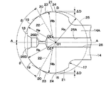
ここで、図1ないし図3は、本発明の第1の実施の形態を示している。図1において、斜軸式液圧回転機としての固定容量型斜軸式油圧モータ1(以下、油圧モータ1という)は、油圧ポンプ等の油圧源(図示せず)から圧油が供給されることにより、後述の回転軸5を回転駆動するものである。
Here, FIGS. 1 to 3 show a first embodiment of the present invention. In FIG. 1, a fixed displacement type oblique-axis hydraulic motor 1 (hereinafter, referred to as a hydraulic motor 1) as an oblique-axis hydraulic rotating machine is supplied with pressure oil from a hydraulic source (not shown) such as a hydraulic pump. Thus, the rotating
ケーシング2は、油圧モータ1の外殻を構成するもので、このケーシング2は、途中部位が屈曲した筒状をなすケーシング本体3と、後述のヘッドケーシング4とにより構成されている。 The casing 2 forms an outer shell of the hydraulic motor 1, and the casing 2 includes a casing main body 3 having a tubular shape with an intermediate portion bent, and a head casing 4 described later.
ケーシング本体3は、図1中に示すように軸方向の一側に位置する一側筒部3Aと、軸方向他側の他側筒部3Bとにより構成され、一側筒部3Aと他側筒部3Bとの中間部位が屈曲されている。また、ケーシング本体3の一側筒部3Aには、その軸方一側の端部に軸挿通孔3Cが形成されている。
As shown in FIG. 1, the casing body 3 is composed of one side
ヘッドケーシング4は、ケーシング本体3の他側筒部3B側に位置するヘッド側端面に固着されている。このヘッドケーシング4には、一対の給排通路(いずれも図示せず)が形成されている。これらの給排通路のうち高圧側の給排通路は、油圧ポンプ(図示せず)から吐出された圧油を後述する弁板10の給排ポート(図示せず)を介して各シリンダ穴9内に供給する。また、低圧側の給排通路は、後述する弁板10の給排ポート側からタンク(図示せず)側に向けて戻り油を排出する。
The head casing 4 is fixed to a head-side end surface located on the other
回転軸5は、ケーシング本体3の一側筒部3A内に設けられている。この回転軸5は、油圧モータ1の出力軸を構成し、ケーシング本体3の一側筒部3A内に軸受等を介して回転自在に設けられている。そして、回転軸5の一端側は、軸挿通孔3Cを通じてケーシング本体3の外部に突出し、例えば遊星歯車減速装置等の油圧モータによって駆動される機器類(図示せず)に連結される。
The
一方、ケーシング本体3の一側筒部3A内を他側筒部3Bに向けて延びる回転軸5の基端側(他端側)には、回転軸5と一体に回転するドライブディスク6が一体的に設けられている。このドライブディスク6は、ケーシング本体3の一側筒部3Aと他側筒部3Bとの境界部近傍となる位置に配置されている。
On the other hand, a
そして、ドライブディスク6には、後述のシリンダブロック7と対向する他側端面の中心側に位置し後述するセンタシャフト11の球形部11Aが摺動可能に連結され中心側に位置するセンタシャフト用凹球面6Aと、センタシャフト用凹球面6Aの径方向外側に位置して周方向に互いに離間し後述する各テーパピストン13の継手部17がそれぞれ揺動可能に連結される回転伝達用の複数のテーパピストン用凹球面6Bとが設けられている。テーパピストン用凹球面6Bは、球面中心O1および半径Raの凹球面として形成されている。テーパピストン用凹球面6Bは、本発明の凹球面を構成している。
The
シリンダブロック7は、ケーシング2内に回転可能に設けられている。このシリンダブロック7は、後述のセンタシャフト11、各テーパピストン13等を介してドライブディスク6に連結され回転軸5と一体に回転するものである。ここで、シリンダブロック7は、肉厚な円筒状に形成され、その中心部には、後述のセンタシャフト11が摺動可能に挿嵌されるセンタ穴8が回転中心軸に沿って穿設されている。また、シリンダブロック7には、センタ穴8を中心として周方向に一定の間隔をもって離間し軸方向に延びた複数本(通常5本、7本または9本等の奇数本)のシリンダ穴9(1本のみ図示)が穿設されている。
The
シリンダブロック7のうちヘッドケーシング4側の端面は、後述の弁板10に摺接する凹湾曲面状の摺動面7Aとなっている。シリンダブロック7の摺動面7Aと各シリンダ穴9との間には、摺動面7A側で弁板10に連通、遮断される複数のシリンダポート9A(1本のみ図示)が形成されている。
The end surface of the
弁板10は、ケーシング2のヘッドケーシング4とシリンダブロック7との間に設けられている。この弁板10は、シリンダブロック7に対面する一側面が凸湾曲状の切換面10Aとなり、他側面は平坦面となってヘッドケーシング4に固着されている。シリンダブロック7は、その摺動面7Aが弁板10の切換面10Aに対して摺接しつつ回転することにより、各シリンダ穴9に対する圧油の供給,排出が行われる。
The
即ち、弁板10には、眉形状をなす一対の給排ポート(図示せず)が周方向に延びて形成され、これらの給排ポートは、ヘッドケーシング4に形成された一対の給排通路(図示せず)に連通している。そして、給排ポートは、シリンダブロック7の回転に伴って各シリンダ穴9のシリンダポート9Aと間欠的に連通する。
That is, a pair of supply / discharge ports (not shown) having an eyebrow shape are formed in the
この場合、高圧側となる一方の給排ポートは、一対の給排通路のうち高圧側の給排通路に接続され、油圧ポンプ(図示せず)から吐出された圧油を各シリンダ穴9内に供給する。また、低圧側となる他方の給排ポートは、一対の給排通路のうち低圧側の給排通路に接続され、各シリンダ穴9から排出される戻り油をタンク(図示せず)側に向けて排出するものである。
In this case, one supply / discharge port on the high pressure side is connected to the supply / discharge passage on the high pressure side of the pair of supply / discharge passages, and pressurized oil discharged from a hydraulic pump (not shown) is provided in each
センタシャフト11は、シリンダブロック7のセンタリングを行うためにセンタ穴8に挿嵌して設けられている。このセンタシャフト11は、一端側が球形部11Aとなり、他端側には有底状のばね収容穴11Bが形成されている。そして、センタシャフト11の球形部11Aは、ドライブディスク6の中心側に形成されたセンタシャフト用凹球面6Aに摺動可能に嵌合されている。
The center shaft 11 is provided by being inserted into the center hole 8 for centering the
ばね12は、センタシャフト11とシリンダブロック7との間に設けられている。このばね12は、センタシャフト11のばね収容穴11B内に配置され、シリンダブロック7を弁板10の切換面10Aに向けて常時付勢している。これにより、シリンダブロック7は、その摺動面7Aを弁板10の切換面10Aに密着させた状態で弁板10に対して正方向または逆方向に相対回転するものである。
The
複数のテーパピストン13(1本のみ図示)は、シリンダブロック7の各シリンダ穴9内にそれぞれ往復動可能に挿嵌されている。図2に示すように、これらのテーパピストン13は、一端側から他端側に向けテーパ状に拡径して形成されたピストン本体部14と、ピストン本体部14の一端側に一体に形成された球形の継手部17と、ピストン本体部14の他端側の端面から継手部17側に向けてテーパピストン13内をピストン軸方向に延び潤滑油が流通する油孔26とを含んで構成されている。
A plurality of taper pistons 13 (only one is shown) are reciprocally inserted into
即ち、これらのテーパピストン13は、軸方向の一側が球面をなしてドライブディスク6のテーパピストン用凹球面6Bに揺動自在に支持された継手部17となり、軸方向の他側がシリンダブロック7の各シリンダ穴9に往復動可能に挿嵌されたピストン本体部14となっている。
That is, these
ピストン本体部14は、一端側に位置して継手部17に一体的に接続された接続部14Aと、他端側に位置して接続部14Aに一体的に接続されシリンダ穴9内に摺動可能に挿嵌されたテーパ部14Bとにより構成されている。テーパ部14Bには、シリンダ穴9に接触するシリンダ内面接触部14Cが形成されており、テーパ部14Bの外周側には、シリンダ内面接触部14Cを挟んだ位置に、シリンダ穴9との間のシール性を確保するためのピストンリング等からなるシール部材15,16等が装着されている。シリンダ内面接触部14Cの直径は、シリンダ穴9の内径より若干小さく構成されている。テーパピストン13は、本発明のピストンを構成している。
The
次に、テーパピストン13の継手部17について説明する。
Next, the joint 17 of the tapered
テーパピストン13の継手部17は、球面をなしドライブディスク6のテーパピストン用凹球面6B内に揺動(摺動)可能に連結されている。継手部17とテーパピストン用凹球面6Bとの間には、シリンダ穴9内に供給された油液の一部が潤滑油となって油孔26側から補給される。そして、継手部17は、ピストン軸方向の一側(先端側)に位置してピストン軸A−Aと直交する平坦面18と、平坦面18からピストン軸方向の他側(ピストン本体部14側)に向けて球面となって延びる大径部としての第1曲面19と、第1曲面19からピストン軸方向の他側に向けて延び第1曲面19よりも小径に形成された小径部としての第2曲面21とを含んで構成されている。
The
図3に示すように、第1曲面19は、球面中心O1および半径Raの曲面(円弧形状)として形成されている。この場合、球面中心O1は、ピストン本体部14の中心軸線ともなるピストン軸A−A上に位置している。第1曲面19は、継手部17の球面のうちピストン軸方向の一側(先端側)を構成している。具体的には、第1曲面19は、継手部17の先端側から基端側に向けて端点20までの範囲を構成している。この場合、端点20は、球面中心O1を通るテーパピストン13のピストン軸A−A(図3中の一点鎖線A−A)とのなす角θが下記数1に示される範囲に位置している。端点20の位置(角度θ)は、後述する寸法差ΔDとの関係から算出される耐摩耗性および機械効率等に基づいて実験等により設定される。
As shown in FIG. 3, the first

組立性の確保等のために、テーパピストン用凹球面6Bの半径は、第1曲面19の半径Raよりわずかに大きい。第1曲面19は、ドライブディスク6のテーパピストン用凹球面6Bと摺動(接触)する部位となり、テーパピストン用凹球面6Bとの間に潤滑油による薄い油膜が形成される部位である。
The radius of the concave
一方、第2曲面21は、継手部17の球面のうちピストン軸方向の他側(基端側)を構成している。第2曲面21は、第2曲面21を形成する円弧の中心O2および半径Rb(Rb<Ra)の曲面(円弧形状)として形成され、端点20からピストン軸方向の他側(ピストン本体部14側)に向けて延びている。第2曲面21は、O2を中心とし半径Rbの円弧をピストン軸A−Aを中心に回転させることにより形成される曲面である。第2曲面21を形成する円弧の中心O2は、第1曲面19の球面中心O1と端点20とを結ぶ点線22上に位置している。
On the other hand, the second
これにより、第1曲面19と第2曲面21とが接続される端点20では、第1曲面19の接線と第2曲面21の接線とが共通な共通接線23となって連接している。その結果、端点20における第1曲面19と第2曲面21とが滑らかに接続(連接)されるので、端点20を流通する潤滑油を効率よく流通させることができ、面圧の増加を抑制することができる。
Thus, at the
また、第2曲面21を形成する円弧の半径Rbは、第1曲面19の半径Raよりも小さく形成されている。第2曲面21の半径Rbは、第1曲面19の球面中心O1を通ってピストン軸A−Aと直交する交線B−B(図3中の一点鎖線B−B)が継手部17の球面と交わる端点24の位置で、第2曲面21と第1曲面19を延長させた場合の仮想線25(図3中の二点鎖線25)との寸法差ΔDが所定の値となるように設定されている。この場合、端点24の位置での第2曲面21と第1曲面19を延長させた場合の仮想線25との寸法差ΔDは、下記数2に示される範囲に設定されている。寸法差ΔDに基づく第2曲面21の半径Rbは、第1曲面19との関係から実験等により設定される。
Further, the radius Rb of the arc forming the second
寸法差ΔDは、継手部17の先端側から基端側に向けて流通する潤滑油の流路の大きさを設定するものである。このように寸法差ΔDを設定することにより、潤滑油を効率よく流通させることができるので、圧こもりを低減させることができる。
The dimensional difference ΔD sets the size of the flow path of the lubricating oil flowing from the distal end side to the proximal end side of the
このようにテーパピストン13の継手部17は、ピストン軸方向の先端側に位置してテーパピストン用凹球面6Bに摺接する第1曲面19と、ピストン軸方向の基端側(ピストン本体部14側)に位置して第1曲面19に連接し、端点24の位置でテーパピストン用凹球面6Bとの間に所定の寸法差ΔDを有する第2曲面21とにより構成されている。即ち、テーパピストン13の継手部17は、継手部17のピストン軸方向の先端側から端点20までが球面中心O1からの寸法Raとなり、端点20から継手部17の基端側に向けて球面中心O1からの寸法が徐々に小さくなるように形成されている。
As described above, the
油孔26は、テーパピストン13の内部をピストン軸方向に延びて穿設されている。この油孔26は、テーパピストン13のピストン本体部14をピストン軸方向に延びる油路26Aと、一端側が継手部17の平坦面18に開口し、他端側が油路26Aに連通した吐出路26Bとにより構成されている。これにより、シリンダ穴9から油路26Aに導かれた潤滑油は、吐出路26Bの細孔26B1を介してテーパピストン用凹球面6Bと継手部17との間に吐出される。そして、吐出された潤滑油は、テーパピストン用凹球面6Bと第1曲面19との間、テーパピストン用凹球面6Bと第2曲面21との間、さらに寸法差ΔDによって形成される隙間を通ってケーシング2内の空間に流出する。
The
本実施の形態による斜軸式の油圧モータ1は、上述の如き構成を有するもので、以下その作動について説明する。 The oblique-axis hydraulic motor 1 according to the present embodiment has the above-described configuration, and its operation will be described below.
まず、油圧モータ1の回転軸5を駆動するときには、油圧ポンプ(図示せず)から吐出された圧油をヘッドケーシング4に形成した高圧側の給排通路、弁板10の給排ポートを介して各シリンダ穴9内へ順次供給し、このときの油圧力で各テーパピストン13をシリンダ穴9からドライブディスク6側に向けて順次伸長(突出)させる。また、各シリンダ穴9からの戻り油は、各テーパピストン13がシリンダ穴9内へと縮小する方向に変位するに伴って低圧側の給排ポート、給排通路からタンク側に向けて排出される。
First, when the
このとき、前記圧油が順次供給される各シリンダ穴9内では、内部に挿嵌されたテーパピストン13の突出側端部となる継手部17がドライブディスク6のテーパピストン用凹球面6B側に順次押付けられる。これにより、ドライブディスク6には、回転軸5を中心とした回転力が発生し、この回転力は回転軸5の先端側からモータ出力として取出される。
At this time, in each of the cylinder holes 9 to which the pressure oil is sequentially supplied, the
ところで、上述した従来技術では、ピストンの継手部とドライブディスクの凹球面との球径差が小さすぎると、潤滑油の圧こもりによるピストンの浮き上がりが発生して、潤滑油の漏らし量が過大となる虞がある。一方、ピストンの継手部とドライブディスクの凹球面との球径差が大きいと、継手部と凹球面との間の面圧が大きくなり、機械効率が低減する虞がある。 By the way, in the above-described conventional technology, if the spherical diameter difference between the joint portion of the piston and the concave spherical surface of the drive disk is too small, the piston is lifted due to pressure build-up of the lubricating oil, and the leakage amount of the lubricating oil is excessive. There is a risk of becoming. On the other hand, if the spherical diameter difference between the joint portion of the piston and the concave spherical surface of the drive disk is large, the surface pressure between the joint portion and the concave spherical surface increases, and the mechanical efficiency may be reduced.
そこで、本実施の形態では、テーパピストン13の継手部17の球面をドライブディスク6のテーパピストン用凹球面6Bに摺動(接触)する第1曲面19と、第1曲面19よりも小径な第2曲面21とにより構成している。
Therefore, in the present embodiment, the first
第1曲面19は、継手部17のうちピストン軸方向の一側(先端側)に位置して、球面中心O1を通るテーパピストン13のピストン軸A−Aとのなす角θが40°以上70°以下(40°≦θ≦70°)までの間に位置する端点20までの範囲を構成している。また、第1曲面19は、ドライブディスク6のテーパピストン用凹球面6Bと同等の球面中心O1および半径Raの円弧形状となっている。即ち、第1曲面19は、テーパピストン用凹球面6Bと摺動(接触)する部位となっている。
The first
一方、第2曲面21は、継手部17のうちピストン軸方向の他側(基端側)に位置して、端点24の位置で寸法差ΔDが所定の値(12.5μm以上30μm以下)となるように、中心O2および半径Rb(Rb<Ra)の円弧形状となっている。即ち、第2曲面21は、継手部17とテーパピストン用凹球面6Bとの間で潤滑油が適正(円滑)に流通する部位となっている。
On the other hand, the second
かくして、第1の実施の形態によれば、テーパピストン13の継手部17の球面は、継手部17のうち軸方向の一側に位置して球面中心O1を有し、該球面中心O1を通るテーパピストン13のピストン軸A−Aとのなす角θが40°以上70°以下までの間でドライブディスク6のテーパピストン用凹球面6Bと摺動する第1曲面19と、第1曲面19から軸方向他側に向けて接続し第1曲面19よりも小径に形成された第2曲面21とからなっている。
Thus, according to the first embodiment, the spherical surface of the
これにより、継手部17の第1曲面19とテーパピストン用凹球面6Bとが接触して、十分な接触面積を確保することができるので、面圧を低減することができる。また、第2曲面21により継手部17とテーパピストン用凹球面6Bとの間を流通する潤滑油の漏らし量を適正にすることができる。これにより、油圧モータ1の入力動力に対する出力動力の損失を低減させて機械効率を向上させることができる。なお、ピストン軸A−Aとのなすθが40°よりも小さくなると、接触面積が小さくなり面圧が大きくなる。一方、ピストン軸A−Aとのなす角θが70°よりも大きくなると、漏らし量が少なくなり圧こもりによる浮上がりが大きくなる。
As a result, the first
また、第1曲面19の球面中心O1を通ってピストン軸A−Aと直交する線B−Bが継手部17の球面と交わる端点24の位置で第2曲面21と第1曲面19を延長させた場合の仮想線25との寸法差ΔDは、12.5μm以上30μm以下に設定されている。
Further, the second
これにより、端点24の位置での潤滑油の流通面積が確保され、潤滑油の漏らし量を適正に保つことができるので、潤滑油の圧こもりによるテーパピストン13の浮き上がりを低減することができる。なお、寸法差ΔDが12.5μmよりも小さくなると、漏らし量が少なくなり圧こもりによる浮き上がりが大きくなる。一方、寸法差ΔDが30μmを越えると、漏らし量が多くなり機械効率が低下する。
Thereby, the flow area of the lubricating oil at the position of the
また、第1曲面19と第2曲面21とが接続される端点20では、第1曲面19の接線と第2曲面21の接線とが共通(共通接線23)となって連接している。これにより、第1曲面19と第2曲面21との接続部(端点20)を滑らかにすることができるので、端点20での面圧の増加を抑制することができると共に、端点20での潤滑油の流れを円滑に行うことができる。
Further, at an
次に、図4は本発明の第2の実施の形態を示している。第2の実施の形態の特徴は、継手部31を第1曲面19と第2曲面21とに加えて第3曲面32を設ける構成としたことにある。なお、本実施の形態では、上述した第1の実施の形態と同一の構成要素に同一符号を付し、その説明を省略するものとする。また、図4中では、中心(O1,O2,O3)および半径(Ra,Rb,Rc)等を図4中の紙面上側に位置する継手部31の球面について示し、紙面下側の球面については同様であるので省略するものとする。
Next, FIG. 4 shows a second embodiment of the present invention. The feature of the second embodiment resides in that a
継手部31は、球面をなしドライブディスク6のテーパピストン用凹球面6B内に揺動(摺動)可能に連結されている。そして、継手部31は、ピストン軸方向の一側(先端側)に位置する平坦面18と、平坦面18からピストン軸方向の他側(ピストン本体部14側)に向けて延びる大径部としての第1曲面19と、第1曲面19からピストン軸方向の他側に向けて延びる小径部としての第2曲面21と、第2曲面21からピストン軸方向の他側に向けて延びる第3曲面32とを含んで構成されている。即ち、第1曲面19は、継手部31の球面のうち先端側を構成している。また、第2曲面21は、継手部31の球面のうち中央部を構成している。そして、第3曲面32は、継手部31の球面のうち基端側を構成している。
The
図4に示すように、第3曲面32は、第3曲面32を形成する円弧の中心O3および半径Rc(Rb<Ra<Rc)の曲面(円弧形状)として形成され、端点24からピストン軸方向の他側(ピストン本体部14側)に向けて延びている。第3曲面32は、O3を中心とし半径Rcの円弧をピストン軸A−Aを中心に回転させることにより形成される曲面である。第3曲面32を形成する円弧の中心O3は、第2曲面21を形成する円弧の中心O2と端点24とを結ぶ点線33上に位置している。
As shown in FIG. 4, the third
これにより、第2曲面21と第3曲面32とが接続される端点24では、第2曲面21の接線と第3曲面32の接線とが共通な共通接線34となって連接している。その結果、端点24における第2曲面21と第3曲面32とが滑らかに接続(連接)されるので、端点24を流通する潤滑油を効率よく流通させることができる。
Thus, at the
また、端点24の位置での第2曲面21と第1曲面19を延長させた場合の仮想線25との寸法差ΔDは、下記数3に示す範囲に設定されている。寸法差ΔDに基づく第2曲面21の半径Rbは、第1曲面19との関係から実験等により設定される。
The dimensional difference ΔD between the second
そして、第3曲面32の半径Rcは、第1曲面19の半径Raと第2曲面21の半径Rbよりも大きく形成されている(Rb<Ra<Rc)。即ち、第3曲面32は、第1曲面19および第2曲面21よりも緩やかな曲面形状となっている。これにより、第3曲面32とテーパピストン用凹球面6B(仮想線25)との間の隙間寸法は、端点24からピストン軸方向の他側に向けて上記寸法差ΔDから緩やかに小さくなる。従って、高圧時におけるテーパピストン用凹球面6Bと継手部31との間からの潤滑油の漏れ量を少なくすることができる。
The radius Rc of the third
かくして、このように構成される第2の実施の形態においても、第1の実施の形態と同様の作用、効果を得ることができる。特に、第2の実施の形態では、継手部31のピストン軸方向の他側を第1曲面19および第2曲面21よりも緩やかな曲面形状(円弧形状)としている。これにより、高圧時における潤滑油の漏れ量を少なくすることができ、機械効率を向上させることができる。即ち、第3曲面32の半径Rcを大きくすることにより、継手部17とテーパピストン用凹球面6Bとの最も他側(ピストン本体部14側)の隙間を小さくし、高圧でも潤滑油の漏れを少なくできる。これにより、機械効率を向上させることができる。
Thus, in the second embodiment configured as described above, the same operation and effect as those in the first embodiment can be obtained. In particular, in the second embodiment, the other side of the
次に、図5は本発明の第3の実施の形態を示している。第3の実施の形態の特徴は、継手部41に網目状の加工溝42を設ける構成としたことにある。なお、本実施の形態では、上述した第1の実施の形態と同一の構成要素に同一符号を付し、その説明を省略するものとする。
Next, FIG. 5 shows a third embodiment of the present invention. The feature of the third embodiment is that the
継手部41は、球面をなしドライブディスク6のテーパピストン用凹球面6B内に揺動(摺動)可能に連結されている。そして、継手部41は、ピストン軸方向の一側(先端側)に位置する平坦面18と、平坦面18からピストン軸方向の他側(ピストン本体部14側)に向けて延びる大径部としての第1曲面19と、第1曲面19からピストン軸方向の他側に向けて延びる小径部としての第2曲面21とを含んで構成されている。
The
図5に示すように、継手部41には、ピストン軸A−Aに対して傾斜する方向に延びる網目状の加工溝42が形成されている。この加工溝42は、吐出路26Bから吐出された潤滑油が流通するもので、潤滑油を第1曲面19とテーパピストン用凹球面6Bとの摺動面全体に行き渡らせることができる。これにより、さらなる圧こもりの低減および摺動面の潤滑性向上による摩擦ロスを低減させることができるので、機械効率をさらに向上させることができる。
As shown in FIG. 5, the joint 41 has a mesh-shaped
なお、上述した第1の実施の形態では、ピストン本体部14にテーパ部14Bを備えたテーパピストン13を用いた場合を例に挙げて説明した。しかし、本発明はこれに限らず、例えばピストン本体部がピストン軸方向に単一の径半径となったピストンに適用してもよい。即ち、球形状の継手部を有するピストンまたはロッドであればいずれにも適用することができる。このことは、第2,第3の実施の形態についても同様である。
In the first embodiment described above, the case where the
また、上述した第1の実施の形態では、端点20で第1曲面19と第2曲面21とが共通接線23を有する場合を例に挙げて説明した。しかし、本発明はこれに限らず、例えば端点20における第1曲面19の接線と第2曲面21の接線とが異なってもよい。このことは、第2の実施の形態における第2曲面21と第3曲面32との接続部位である端点24および第3の実施の形態についても同様である。
Further, in the first embodiment described above, the case where the first
また、上述した第2の実施の形態では、継手部31の球面は、第1曲面19、第2曲面21、および第3曲面32により構成した場合を例に挙げて説明した。しかし、本発明はこれに限らず、例えば継手部の球面を4個以上の曲面により構成してもよい。このことは、第3の変形例についても同様である。
Further, in the above-described second embodiment, the case where the spherical surface of the
また、各実施の形態では、斜軸式液圧回転機として斜軸式で固定容量型の油圧モータ1を例に挙げて説明した。しかし、本発明はこれに限らず、例えば斜軸式で可変容量型の油圧モータに適用してもよい。さらには、斜軸式で固定容量型または可変容量型の油圧ポンプに適用してもよい。 Further, in each embodiment, the oblique-axis fixed-displacement type hydraulic motor 1 has been described as an example of the oblique-axis hydraulic rotating machine. However, the present invention is not limited to this, and may be applied to, for example, an oblique-axis variable displacement hydraulic motor. Further, the present invention may be applied to an oblique axis type fixed displacement or variable displacement hydraulic pump.
1 油圧モータ(斜軸式液圧回転機)
2 ケーシング
5 回転軸
6 ドライブディスク
6B テーパピストン用凹球面
7 シリンダブロック
9 シリンダ穴
13 テーパピストン(ピストン)
14 ピストン本体部
17,31,41 継手部
19 第1曲面(大径部)
20 端点(第1の端点)
21 第2曲面(小径部)
23 共通接線
24 端点(第2の端点)
42 加工溝
A−A ピストン軸
B−B 交線
O1 第1曲面の球面中心
O2 第2曲面の円弧の中心
1. Hydraulic motor (oblique-axis hydraulic rotary machine)
2
14 Piston
20 endpoints (first endpoint)
21 2nd curved surface (small diameter part)
23 common
42 Machining groove AA Piston axis BB Intersection line O1 Center of spherical surface of first curved surface O2 Center of arc of second curved surface
Claims (3)
前記ピストンは、前記ピストン内の軸方向に形成され潤滑油が流通する油孔を含んで構成されており、
前記ピストンの前記継手部は、前記ピストンにおける軸方向の一側に位置して前記ピストンの中心軸線となるピストン軸に直交して形成された平坦面と、前記ピストンにおける前記平坦面から軸方向の他側に向けて球面に形成された第1曲面と、前記ピストンにおける前記第1曲面から軸方向の他側に向けて前記第1曲面よりも小径に形成された第2曲面とを含んで構成されており、
前記第1曲面は、前記ピストン軸上に球面中心を有する半径Raの曲面として、前記継手部の先端側から基端側に向けて前記第1曲面と前記第2曲面とが接続される第1の端点までの範囲を構成しており、
前記第1の端点と前記球面中心を通る前記ピストン軸とはなす角θを有しており、
前記第2曲面は、前記第1曲面の球面中心と前記第1の端点とを結ぶ仮想線上に中心を有し前記第1曲面の前記半径Raよりも小径である半径Rbの円弧を前記ピストン軸を中心に回転させることにより形成される曲面として、前記継手部の前記第1の端点から軸方向の他側に向けて形成されており、
前記第1の端点では、前記第1曲面の接線と前記第2曲面の接線とが共通な共通接線になって連接しており、
前記第1曲面の前記球面中心を通って前記ピストン軸に直交する交線が前記第2曲面と交わる第2の端点の位置で、前記第2曲面と前記第1曲面とを延長させた場合の仮想線との寸法差は、12.5μm以上30μm以下に設定されており、
前記第1曲面は、前記ドライブディスクの前記凹球面と同等の前記球面中心および前記半径Raの円弧形状で前記凹球面と摺動する部位となっており、
前記第2曲面は、前記寸法差が設定されていることにより前記ドライブディスクの前記凹球面との間で潤滑油が流通する部位となっていることを特徴とする斜軸式液圧回転機。 A cylindrical casing, a rotating shaft located on one side of the casing and rotatably provided via a bearing, and a plurality of concave spherical surfaces located in the casing and provided at an end of the rotating shaft. A drive disk, a cylinder block provided in the casing so as to rotate integrally with the rotating shaft, and having a plurality of cylinder holes extending in the axial direction while being spaced apart in the circumferential direction, and one side in the axial direction is spherical. And a plurality of pistons, each of which has a joint body rotatably supported by the concave spherical surface of the drive disk and a piston body part whose other axial side is reciprocally fitted into each cylinder hole of the cylinder block. In the oblique axis type hydraulic rotary machine provided with
The piston is configured to include an oil hole formed in the piston in the axial direction and through which lubricating oil flows,
The joint portion of the piston is located on one side of the piston in the axial direction and is formed so as to be orthogonal to a piston axis serving as a central axis of the piston. A first curved surface formed into a spherical surface toward the other side, and a second curved surface formed from the first curved surface of the piston toward the other side in the axial direction with a smaller diameter than the first curved surface. Has been
The first curved surface is a curved surface having a radius Ra having a spherical center on the piston axis, and the first curved surface and the second curved surface are connected from the distal end side to the proximal end side of the joint portion. Constitutes the range up to the end point of
Has an angle θ between the first end point and the piston axis passing through the center of the spherical surface,
The second curved surface has a center on an imaginary line connecting the center of the spherical surface of the first curved surface and the first end point, and forms an arc having a radius Rb smaller than the radius Ra of the first curved surface with the piston shaft. As a curved surface formed by rotating about the joint from the first end point of the joint portion toward the other side in the axial direction,
At the first end point, a tangent to the first curved surface and a tangent to the second curved surface are connected to each other as a common tangent,
A case where the second curved surface and the first curved surface are extended at a position of a second end point where an intersection line orthogonal to the piston axis passes through the center of the spherical surface of the first curved surface and intersects with the second curved surface. The dimensional difference from the imaginary line is set to 12.5 μm or more and 30 μm or less,
The first curved surface is a portion that slides on the concave spherical surface in an arc shape having the center of the spherical surface and the radius Ra equivalent to the concave spherical surface of the drive disk,
The oblique-axis hydraulic rotary machine according to claim 1, wherein the second curved surface is a portion through which lubricating oil flows between the concave surface and the concave surface of the drive disk by setting the dimensional difference.
前記第3曲面は、前記第2の端点からピストン軸方向の他側に向けて形成されており、
前記第3曲面を形成する円弧の中心は、前記第2曲面を形成する円弧の中心と前記第2の端点とを結ぶ仮想線上に位置しており、
前記第3曲面を形成する円弧の半径Rcは、前記第1曲面の半径Raと前記第2曲面の半径Rbよりも大きく設定していることを特徴とする請求項1に記載の斜軸式液圧回転機。 The joint portion of the piston is configured to include a third curved surface in addition to the first curved surface and the second curved surface,
The third curved surface is formed from the second end point toward the other side in the piston axial direction,
The center of the arc forming the third curved surface is located on an imaginary line connecting the center of the arc forming the second curved surface and the second end point,
The oblique axis type liquid according to claim 1, wherein a radius Rc of an arc forming the third curved surface is set to be larger than a radius Ra of the first curved surface and a radius Rb of the second curved surface. Pressure rotary machine.
Priority Applications (1)
| Application Number | Priority Date | Filing Date | Title |
|---|---|---|---|
| JP2017032072A JP6672199B2 (en) | 2017-02-23 | 2017-02-23 | Oblique axis type hydraulic rotary machine |
Applications Claiming Priority (1)
| Application Number | Priority Date | Filing Date | Title |
|---|---|---|---|
| JP2017032072A JP6672199B2 (en) | 2017-02-23 | 2017-02-23 | Oblique axis type hydraulic rotary machine |
Publications (3)
| Publication Number | Publication Date |
|---|---|
| JP2018135838A JP2018135838A (en) | 2018-08-30 |
| JP2018135838A5 JP2018135838A5 (en) | 2019-02-21 |
| JP6672199B2 true JP6672199B2 (en) | 2020-03-25 |
Family
ID=63365348
Family Applications (1)
| Application Number | Title | Priority Date | Filing Date |
|---|---|---|---|
| JP2017032072A Active JP6672199B2 (en) | 2017-02-23 | 2017-02-23 | Oblique axis type hydraulic rotary machine |
Country Status (1)
| Country | Link |
|---|---|
| JP (1) | JP6672199B2 (en) |
Families Citing this family (1)
| Publication number | Priority date | Publication date | Assignee | Title |
|---|---|---|---|---|
| JP7005547B2 (en) * | 2019-03-20 | 2022-01-21 | 日立建機株式会社 | Oblique shaft axial piston pump |
-
2017
- 2017-02-23 JP JP2017032072A patent/JP6672199B2/en active Active
Also Published As
| Publication number | Publication date |
|---|---|
| JP2018135838A (en) | 2018-08-30 |
Similar Documents
| Publication | Publication Date | Title |
|---|---|---|
| JP4653176B2 (en) | Oblique shaft type variable displacement pump / motor | |
| JP2009257445A (en) | Tilting pad thrust bearing | |
| JP6672199B2 (en) | Oblique axis type hydraulic rotary machine | |
| JP2010174690A (en) | Valve plate, and piston pump or motor equipped with the same | |
| JP5780948B2 (en) | Axial piston hydraulic pump | |
| JP6640140B2 (en) | Hydraulic rotating machine | |
| JP2012184707A (en) | Swash plate type piston pump | |
| JP6276911B2 (en) | Hydraulic rotating machine | |
| US10385887B2 (en) | Hydraulic machine | |
| KR20150095421A (en) | Piston of Hydraulic Motor or Pump | |
| JP6892084B2 (en) | Valve plate and hydraulic rotary machine | |
| JP3543892B2 (en) | Axial piston type fluid pump / motor | |
| JP5320108B2 (en) | Hydraulic motor | |
| JP7153534B2 (en) | vane pump | |
| KR101984316B1 (en) | Piston slipper for hydraulic pump | |
| JP7005547B2 (en) | Oblique shaft axial piston pump | |
| JP2018135838A5 (en) | ||
| JP2005220789A (en) | Swash plate type fluid compressor | |
| JP6609163B2 (en) | Vane pump | |
| JP4496528B2 (en) | Swash plate type hydraulic rotating machine | |
| JP2023127653A (en) | Hydraulic pressure rotating device | |
| JP6179359B2 (en) | Hydraulic piston pump / motor | |
| JP6668267B2 (en) | Oblique axis type hydraulic rotary machine | |
| JP6572764B2 (en) | Swash plate type piston pump | |
| JP2009108781A (en) | Radial piston pump or motor |
Legal Events
| Date | Code | Title | Description |
|---|---|---|---|
| A521 | Written amendment |
Free format text: JAPANESE INTERMEDIATE CODE: A523 Effective date: 20190110 |
|
| A621 | Written request for application examination |
Free format text: JAPANESE INTERMEDIATE CODE: A621 Effective date: 20190110 |
|
| A131 | Notification of reasons for refusal |
Free format text: JAPANESE INTERMEDIATE CODE: A131 Effective date: 20191001 |
|
| A977 | Report on retrieval |
Free format text: JAPANESE INTERMEDIATE CODE: A971007 Effective date: 20190927 |
|
| A521 | Written amendment |
Free format text: JAPANESE INTERMEDIATE CODE: A523 Effective date: 20191126 |
|
| TRDD | Decision of grant or rejection written | ||
| A01 | Written decision to grant a patent or to grant a registration (utility model) |
Free format text: JAPANESE INTERMEDIATE CODE: A01 Effective date: 20200303 |
|
| A61 | First payment of annual fees (during grant procedure) |
Free format text: JAPANESE INTERMEDIATE CODE: A61 Effective date: 20200304 |
|
| R150 | Certificate of patent or registration of utility model |
Ref document number: 6672199 Country of ref document: JP Free format text: JAPANESE INTERMEDIATE CODE: R150 |