JP6667988B2 - Dispensing device for liquids containing solids - Google Patents
Dispensing device for liquids containing solids Download PDFInfo
- Publication number
- JP6667988B2 JP6667988B2 JP2014191704A JP2014191704A JP6667988B2 JP 6667988 B2 JP6667988 B2 JP 6667988B2 JP 2014191704 A JP2014191704 A JP 2014191704A JP 2014191704 A JP2014191704 A JP 2014191704A JP 6667988 B2 JP6667988 B2 JP 6667988B2
- Authority
- JP
- Japan
- Prior art keywords
- eccentric
- drive shaft
- blade
- dispensing device
- axis
- Prior art date
- Legal status (The legal status is an assumption and is not a legal conclusion. Google has not performed a legal analysis and makes no representation as to the accuracy of the status listed.)
- Expired - Fee Related
Links
- 239000007788 liquid Substances 0.000 title claims description 92
- 239000007787 solid Substances 0.000 title claims description 60
- 238000005520 cutting process Methods 0.000 claims description 153
- 238000002347 injection Methods 0.000 claims description 33
- 239000007924 injection Substances 0.000 claims description 33
- 238000009826 distribution Methods 0.000 claims description 31
- 230000008878 coupling Effects 0.000 claims description 16
- 238000010168 coupling process Methods 0.000 claims description 16
- 238000005859 coupling reaction Methods 0.000 claims description 16
- 238000004891 communication Methods 0.000 claims description 6
- 238000011144 upstream manufacturing Methods 0.000 claims description 2
- 230000033001 locomotion Effects 0.000 description 30
- 238000005096 rolling process Methods 0.000 description 10
- 230000005540 biological transmission Effects 0.000 description 8
- 238000013461 design Methods 0.000 description 8
- 230000000694 effects Effects 0.000 description 7
- 230000009471 action Effects 0.000 description 5
- 239000012530 fluid Substances 0.000 description 5
- 238000010008 shearing Methods 0.000 description 5
- 230000006978 adaptation Effects 0.000 description 4
- 238000011161 development Methods 0.000 description 4
- 239000002002 slurry Substances 0.000 description 4
- 230000007246 mechanism Effects 0.000 description 3
- 238000000034 method Methods 0.000 description 3
- 238000007789 sealing Methods 0.000 description 3
- 230000008859 change Effects 0.000 description 2
- 238000010276 construction Methods 0.000 description 2
- 238000012423 maintenance Methods 0.000 description 2
- 239000000463 material Substances 0.000 description 2
- 230000002093 peripheral effect Effects 0.000 description 2
- 230000010363 phase shift Effects 0.000 description 2
- 230000008569 process Effects 0.000 description 2
- 238000004062 sedimentation Methods 0.000 description 2
- 238000005549 size reduction Methods 0.000 description 2
- 230000001133 acceleration Effects 0.000 description 1
- 238000010586 diagram Methods 0.000 description 1
- 238000006073 displacement reaction Methods 0.000 description 1
- 239000003814 drug Substances 0.000 description 1
- 229940079593 drug Drugs 0.000 description 1
- 238000005516 engineering process Methods 0.000 description 1
- 239000000835 fiber Substances 0.000 description 1
- 238000000265 homogenisation Methods 0.000 description 1
- 238000009434 installation Methods 0.000 description 1
- 239000000203 mixture Substances 0.000 description 1
- 238000009827 uniform distribution Methods 0.000 description 1
- 238000009423 ventilation Methods 0.000 description 1
Images


Classifications
-
- B—PERFORMING OPERATIONS; TRANSPORTING
- B02—CRUSHING, PULVERISING, OR DISINTEGRATING; PREPARATORY TREATMENT OF GRAIN FOR MILLING
- B02C—CRUSHING, PULVERISING, OR DISINTEGRATING IN GENERAL; MILLING GRAIN
- B02C18/00—Disintegrating by knives or other cutting or tearing members which chop material into fragments
- B02C18/06—Disintegrating by knives or other cutting or tearing members which chop material into fragments with rotating knives
-
- A—HUMAN NECESSITIES
- A01—AGRICULTURE; FORESTRY; ANIMAL HUSBANDRY; HUNTING; TRAPPING; FISHING
- A01C—PLANTING; SOWING; FERTILISING
- A01C23/00—Distributing devices specially adapted for liquid manure or other fertilising liquid, including ammonia, e.g. transport tanks or sprinkling wagons
- A01C23/001—Sludge spreaders, e.g. liquid manure spreaders
- A01C23/002—Sludge spreaders, e.g. liquid manure spreaders provided with auxiliary arrangements, e.g. pumps, agitators, cutters
-
- A—HUMAN NECESSITIES
- A01—AGRICULTURE; FORESTRY; ANIMAL HUSBANDRY; HUNTING; TRAPPING; FISHING
- A01C—PLANTING; SOWING; FERTILISING
- A01C3/00—Treating manure; Manuring
- A01C3/06—Manure distributors, e.g. dung distributors
-
- B—PERFORMING OPERATIONS; TRANSPORTING
- B02—CRUSHING, PULVERISING, OR DISINTEGRATING; PREPARATORY TREATMENT OF GRAIN FOR MILLING
- B02C—CRUSHING, PULVERISING, OR DISINTEGRATING IN GENERAL; MILLING GRAIN
- B02C18/00—Disintegrating by knives or other cutting or tearing members which chop material into fragments
- B02C18/02—Disintegrating by knives or other cutting or tearing members which chop material into fragments with reciprocating knives
Description
本発明は、液体のための、特に固体含有液体のための分配装置に関する。本分配装置は、分配チャンバのチャンバ内部空間に通じる注入開口を有する分配チャンバと、チャンバ内部空間をいくつかの接続ポートに接続するいくつかの排出開口を有する第1の有孔ブレードディスクと、ドライブシャフト軸の周りを旋回可能に装着されたブレードドライブシャフトと、を備える。 The invention relates to a dispensing device for liquids, in particular for liquids containing solids. The dispensing apparatus includes a dispensing chamber having an inlet opening communicating with the chamber interior space of the dispensing chamber, a first perforated blade disk having a number of outlet openings connecting the chamber interior space to a number of connection ports, and a drive. A blade drive shaft mounted to be pivotable about a shaft axis.
固体含有液体のための分配装置は種々のアプリケーションにおいて利用され、1つの典型的な例は、例えば、スラリのアプリケーションのための農業技術において利用される。ここで、分配装置の役割は固体混入液体をタンクからいくつかの開口に分配することにあり、その目的は例えば、空間的に標的化された方法で且つ適切に投与される送出の速さで、そのような液体をいくつかの開口を介して分配することである。1つの典型的なアプリケーションは、空間的に標的化され且つ適切に投与されるそのアプリケーションを達成するためにスラリがスラリタンクからいくつかの、例えば5本〜100本のホースに分配される、ドラッグホース装置を介したスラリのアプリケーションである。 Dispensers for solids-containing liquids are used in various applications, one typical example being used in agricultural technology, for example, for slurry applications. Here, the role of the dispensing device is to dispense the solid entrained liquid from the tank to a number of openings, the purpose of which is, for example, in a spatially targeted manner and with a suitably administered delivery speed. Dispense such liquids through several openings. One typical application is a drug in which the slurry is dispensed from a slurry tank into several, eg, 5 to 100 hoses, to achieve that application that is spatially targeted and properly administered Application of slurry via hose device.
そのような分配ユニットにおいて生じる1つの基本的な問題は、システムの性質により、固体混入液体が、大きな断面を有する供給ラインから、各々が小さな断面を有するいくつかの供給ラインに分配される必要がある、という事実から結果としてもたらされる。液体中の固体によって、このシステムによって決定されるプロセスでは複数の小さな断面で詰まりの危険性が生じる。この問題点を解決するために、固体混入液体のための分配装置を、カッティング装置に連結することが基本的に知られている。そのようなカッティング装置の結果として、液体中の固体はより小さくされ、このことは分配装置の中および後段において通路の小さな断面における詰まりの危険性を低減させる。例えば、分配装置に統合されたカッティング装置が知られている。カッティング装置は複数のカッティングブレードを有し、複数のカッティングブレードは有孔ディスクと連動して、液体が有孔ディスクの複数の孔を通過するときに液体に対して剪断作用を発揮する。この剪断作用を生成するために、カッティングブレードは有孔ディスクに対して相対的に移動される。有孔ディスクにおける複数の孔は分配装置の複数の排出開口に対応し、これらの排出開口と流体連通する。 One fundamental problem that arises in such distribution units is that, due to the nature of the system, the solids entrained liquid needs to be distributed from a supply line having a large cross section to several supply lines each having a small cross section. It results from the fact that there is. Due to the solids in the liquid, the process determined by this system creates a risk of clogging in multiple small cross sections. In order to solve this problem, it is basically known to connect a dispensing device for the solids entrained liquid to a cutting device. As a result of such a cutting device, the solids in the liquid are made smaller, which reduces the risk of clogging in the small section of the passage in and after the distributor. For example, a cutting device integrated into a dispensing device is known. The cutting device has a plurality of cutting blades, which in conjunction with the perforated disc exert a shearing action on the liquid as the liquid passes through the perforations of the perforated disc. To create this shearing action, the cutting blade is moved relative to the perforated disc. The plurality of holes in the perforated disk correspond to and are in fluid communication with the plurality of discharge openings of the distributor.
最初に引用された種類の分配装置において生じるもう1つの問題点は、分配装置が異なる複数の負荷状態において運転される必要がある、ということである。ここで、異なる複数の負荷状態は、1つの負荷状態における複数の排出開口のうちの全ての使用と、複数の排出開口のうちのいくつかのみの使用であって他の排出開口が閉鎖される使用と、によって特徴付けられる。たとえそのような異なる複数の負荷状態においても、分配装置が経済的に運転可能であることが望まれ、また、固体の効果的なサイズ低減を用いた、固体混入液体の、信頼性があり且つ一様な分配が望まれる。 Another problem that arises with dispensers of the type cited at the outset is that the dispensers need to be operated at different load conditions. Here, the plurality of different load states are all use of the plurality of discharge openings in one load state and use of only some of the plurality of discharge openings, and the other discharge openings are closed. And use. It is desirable that the dispensing device be economically operable, even at such different loading conditions, and that the solids enriched liquid is reliable and uses an effective size reduction of the solids. Uniform distribution is desired.
固体混入液体の分配に関連するもう1つの問題点は、そのような液体が流動性に関する特性に関連して有する大きな変動性にある。例えば一方では、固体混入液体は、低いまたは高い固体の含有量によって特徴付けられることができ、これは典型的には、液体体積あたりの固体体積として、または全体積に対する固体体積として特徴付けられる。他方では、固体混入液体は、固体成分の材料特性と幾何学的(形状の)特性の観点において大きく異なる場合がある。例えば、固体成分は、剪断力に対して低いまたは高い抵抗力を有することができ、コンパクトな、例えばファイバーまたはシートの意味において球形状または楕円状もしくは平面状の形状を有し、またそれらはもちろん、それらの絶対的な寸法の観点において一般的に異なる。最後に、固体を含んでいる液体はまた、種々の粘着性を有することができる。これらの理由により、複数の種類の、固体混入液体のための分配装置を作成することが知られている。例えば、そのような分配装置は、小さなまたは大きな複数の排出開口、1つ、2つ、3つ、またはより多くのカッティングブレード、異なる複数の形状および複数の孔を有する有孔ディスクブレードを有し、また、カッティング部材と有孔ディスクとの間の種々の相対的な速度を有する。確かに、多くの場合、固体混入液体のある特性への十分な適合、したがって固体混入液体の良好な分配は、分配装置の、幾何学的(形状の)パラメータ、材料に関連するパラメータ、および運転上の点に関連するパラメータのこの適合によって達成される。しかしながら、既知の分配装置におけるこの種類の構成は、以下の欠点を有する。すなわち、運転パラメータ、例えばカッティングブレードと有孔ディスクとの間の相対的な速度、を変更することによる制限された方法で、固体混入液体の特性の変化に対応することが可能であるのみであり、また、ある固体混入液体の分配から異なる特性を有した固体混入液体の分配に分配装置を切り換えるために、分配装置の機械的な部品を交換する必要が頻繁にある。ユーザ側で労力を要することがほとんどない、種々の固体混入液体のためのそのような分配装置の適合のための、より良い実現性をここで提供することが望まれる。 Another problem associated with the distribution of solids entrained liquids lies in the large variability that such liquids have in relation to flow properties. For example, on the one hand, solids entrained liquids can be characterized by a low or high solids content, which is typically characterized as solids volume per liquid volume or solids volume to total volume. On the other hand, solids entrained liquids can differ significantly in terms of material properties and geometric (shape) properties of the solid components. For example, the solid components can have a low or high resistance to shear forces, have a compact, for example spherical or elliptical or planar shape in the sense of fibers or sheets, and of course they can Generally differ in terms of their absolute dimensions. Finally, liquids containing solids can also have various stickiness. For these reasons, it is known to create dispensers for several types of solids entrained liquids. For example, such a dispensing device has small or large multiple discharge openings, one, two, three or more cutting blades, a perforated disk blade having different shapes and holes. It also has various relative speeds between the cutting member and the perforated disc. Indeed, in many cases, a good adaptation to certain properties of the solids entrained liquid, and thus a good distribution of the solids enriched liquid, is due to the geometric (shape) parameters, material-related parameters and operation of the dispensing device. This is achieved by this adaptation of the parameters associated with the above points. However, this type of configuration in the known dispensing device has the following disadvantages. That is, it is only possible to respond to changes in the properties of the solids entrained liquid in a limited way by changing operating parameters, for example the relative speed between the cutting blade and the perforated disc. Also, it is frequently necessary to replace the mechanical components of the dispensing device in order to switch the dispensing device from dispensing one solid-contaminated liquid to dispensing a solid-contaminated liquid with different characteristics. It is desired to provide here a better feasibility for the adaptation of such a dispensing device for different solids entrained liquids with little effort on the part of the user.
運転中の自動車から液体を送出するために分配装置が使用されるアプリケーションにおいて、体積流量は、種々の運転速度と望まれる送出量(m3/ha)によって大きく変動し、または変動されるべきである、という付加的な問題が生じる。したがって、結果としてサイズ低減の効果を低下させることなく、送出される量に関して大きな範囲で変化するように動作可能な分配装置が必要である。 In applications where the dispensing device is used to deliver liquid from a driving vehicle, the volumetric flow rate may or may vary widely with different operating speeds and the desired delivery rate (m 3 / ha). Yes, there is an additional problem. Therefore, there is a need for a dispensing device that is operable to vary over a large range in the delivered volume without consequently reducing the size reduction effect.
本発明によれば、これらの問題点は低減され、また、多くのアプリケーションにおいて、最初に説明される構成を有する分配装置によって完全に解決される。本分配装置は、ブレードドライブシャフトに接続され、ドライブシャフト軸から離れて位置する第1の偏心軸を定義する第1の偏心部材と、第1の偏心部材に接続され、第1の有孔ブレードディスクに接して配置されるカッティングエッジを有し、第1の偏心部材の手段によって第1の有孔ブレードディスクに対して相対的に移動可能である第1のカッティングブレードと、によって特徴付けられる。 According to the invention, these problems are reduced and, in many applications, are completely solved by a dispensing device having the configuration described first. The dispensing device includes a first eccentric member connected to the blade drive shaft and defining a first eccentric axis remote from the drive shaft axis, and a first perforated blade connected to the first eccentric member. A first cutting blade having a cutting edge disposed adjacent to the disk and movable relative to the first perforated blade disk by means of a first eccentric member.
本発明によれば、カッティングブレードは、偏心部材の手段によって、有孔ブレードディスクに対して相対的に移動される。結果として、カッティングブレードの偏心運動は、有孔ブレードディスクに沿ってもたらされる。カッティングブレードは、偏心軸の周りを能動的にまたは受動的に駆動される方法で、偏心部材の移動と重なってカッティングエッジとともに回転するまたは回転を可能にすることが特に好ましい。この構成において、カッティングブレードの偏心軸の周りの回転運動は、ブレードドライブシャフトの周りの偏心軸の回転運動と重ねられる。カッティングブレードはここでは、固体混入液体の種々の粘着性特性およびこの液体中の固体の種々の特性の耐性を特に有する軌道上を移動し、そのような固体混入液体の広い範囲のパラメータをカバーし、このためにカッティングブレードまたは有孔ブレードディスクに対して構造的な変化をさせる必要はない。特に、カッティングブレードが偏心部材上に回転可能に装着され、したがって偏心部材に関して受動的な回転運動を行うことできるのであれば、好ましい。運動のこの能動的な実現性の結果として、カッティングブレードは、偏心部材に対して相対的に、液体中の固体からの各点毎の負荷を、より良く回避する。特に、より好ましいてこの作用を用いて抵抗力のある固体を切削して、単一の軸の周りを回転する複数のカッティングブレードにおけるカッティングブレードに沿ってより均等にウェアを分配することができる。ブレードドライブシャフトは好ましくは、チャンバ内部空間に配置され、有孔ブレードディスクに、または分配チャンバの外側に、回転可能に装着されるために、有孔ブレードディスクを貫通して延びることができる。 According to the invention, the cutting blade is moved relative to the perforated blade disk by means of an eccentric. As a result, an eccentric movement of the cutting blade is effected along the perforated blade disk. It is particularly preferred that the cutting blade overlaps the movement of the eccentric and rotates or rotates with the cutting edge in a manner that is actively or passively driven about an eccentric axis. In this configuration, the rotational movement of the cutting blade about the eccentric axis is superimposed on the rotational movement of the eccentric axis about the blade drive shaft. Here, the cutting blade travels in orbit, which has in particular the resistance of the various sticky properties of the solid-enriched liquid and of the various properties of the solids in this liquid, covering a wide range of parameters of such solid-enriched liquids. It is not necessary to make any structural changes to the cutting blade or the perforated blade disk for this. In particular, it is advantageous if the cutting blade is rotatably mounted on the eccentric so that a passive rotational movement can be performed with respect to the eccentric. As a result of this active possibility of movement, the cutting blade better avoids point-by-point loading from solids in the liquid, relative to the eccentric. In particular, the more preferred leverage can be used to cut resistant solids to distribute the wear more evenly along the cutting blades of a plurality of cutting blades rotating about a single axis. The blade drive shaft is preferably located in the chamber interior space and can extend through the perforated blade disk for rotatable mounting on the perforated blade disk or outside the distribution chamber.
固体混入液体は、注入開口を通って分配チャンバのチャンバ内部空間内に注入される。固体混入液体は、チャンバ内部空間から、有孔ブレードディスクにおける複数の排出開口を通過して、複数のチャンバ排出開口へ至る。これらチャンバ排出開口の数は、有孔ブレードディスクにおける排出開口の数に対応することができ、または、それと異なることができる。有孔ブレードディスクにおける複数の排出開口を通過するとき、固体は、有孔ブレードディスクに対するカッティングエッジの相対的な運動の手段によって生成される剪断作用によって、大きさが縮小される。カッティングブレードは好ましくは、チャンバ内部空間の方向を向いている有孔ブレードディスクの側部上に、または、チャンバ内部空間から離れた方向を向いている有孔ブレードディスクの側部上に配置されることができる。カッティングブレードは、有孔ブレードディスクにおける複数の排出開口でカッティングエッジと協働する1つ、2つ、またはそれよりも多くのカッティングエッジを有する単一のカッティング部材によって具現化されることができる。同様に、カッティングブレードは、1つ、2つ、またはそれよりも多くのカッティングエッジを有する2つまたはそれよりも多くのカッティング部材を備えることができる。 The solids entrained liquid is injected into the chamber interior space of the distribution chamber through the injection opening. The solids entrained liquid passes from the chamber interior through a plurality of discharge openings in the perforated blade disk to a plurality of chamber discharge openings. The number of these chamber outlet openings can correspond to or be different from the number of outlet openings in the perforated blade disk. As it passes through the plurality of discharge openings in the perforated blade disk, the solids are reduced in size by shearing action created by means of relative movement of the cutting edge with respect to the perforated blade disk. The cutting blade is preferably arranged on the side of the perforated blade disk facing the chamber interior space or on the side of the perforated blade disk facing away from the chamber interior space. be able to. The cutting blade can be embodied by a single cutting member having one, two, or more cutting edges cooperating with the cutting edges at a plurality of discharge openings in the perforated blade disk. Similarly, a cutting blade can include two or more cutting members having one, two, or more cutting edges.
第1の好ましい実施形態によれば、本発明に係る分配装置は、偏心部材をブレードドライブシャフトに接続し、偏心部材上の第1の回り止め位置において、偏心部材を、ドライブシャフト軸に対する第1の偏心軸の第1の偏心度を有するように位置付け、偏心部材上の第2の回り止め位置において、偏心部材を、第1の偏心度よりも大きい、ドライブシャフト軸に対する第1の偏心軸の第2の偏心度を有するように位置付ける、連結部材によって、さらに発展されることができる。この実施形態において、ドライブシャフト軸に対する偏心軸の偏心度は、分配装置の運転中に変更されることができる。このために、連結部材は、偏心部材とブレードドライブシャフトとの間に配置され、2つの回り止め位置においてブレードドライブシャフトを偏心部材に機械的に連結する。その際、第1の回り止め位置において、第2の回り止め位置とは異なる偏心度が達成される。「偏心度」はここでは、偏心軸とドライブシャフト軸との間の間隙として理解されるべきものである。この好ましい実施形態において、分配装置は、2つの異なる偏心度で運転されることができ、その切り換えは、手動作動を用いて、または、例えばある回転数またはトルク等の、ある運転パラメータ閾値を超えることによって、第1の偏心度と第2の偏心度との間で、または第1の回り止め位置と第2の回り止め位置との間で行われることができる。例えば、偏心部材は、第1の回り止め位置において連結部材に係合することができ、また、ブレードドライブシャフトのまたはカッティングブレードの所定の回転速度限度を上回るまたは下回るときに、例えば遠心力またはドラッグトルクの影響によって、回り止め位置に移動することができる。同様に、切り換えは、スイッチレバーまたは他の作動部材の手動での外部作動によって、第1の回り止め位置と第2の回り止め位置との間で行われることができる。 According to a first preferred embodiment, the dispensing device according to the present invention connects the eccentric member to the blade drive shaft, and in a first detent position on the eccentric member, moves the eccentric member to the first with respect to the drive shaft axis. Eccentric shaft having a first eccentricity, and at a second detent position on the eccentric member, moving the eccentric member relative to the drive shaft axis with the first eccentric shaft greater than the first eccentricity. A further development is possible with a coupling member positioned to have a second eccentricity. In this embodiment, the eccentricity of the eccentric shaft with respect to the drive shaft shaft can be changed during operation of the distribution device. For this purpose, the connecting member is arranged between the eccentric member and the blade drive shaft, and mechanically connects the blade drive shaft to the eccentric member at two detent positions. In this case, a different eccentricity is achieved at the first detent position than at the second detent position. "Eccentricity" is here to be understood as the gap between the eccentric axis and the drive shaft axis. In this preferred embodiment, the dispensing device can be operated with two different eccentricities, the switching of which can be performed using manual actuation or exceeding certain operating parameter thresholds, for example a certain speed or torque. Thereby, it can be performed between the first eccentricity and the second eccentricity or between the first detent position and the second detent position. For example, the eccentric member can engage the coupling member in the first detent position, and when above or below a predetermined rotational speed limit of the blade drive shaft or of the cutting blade, such as centrifugal force or drag Due to the influence of the torque, it is possible to move to the detent position. Similarly, switching can be effected between a first detent position and a second detent position by manual external actuation of a switch lever or other actuating member.
原則として、理解されるべきことは、本実施形態において、偏心部材が、連結部材に、第1または第2の回り止め位置のいずれかにおいて、2値で位置付けられる、ということである。1つの代替の実施形態において、しかしながら、偏心部材はまた、連結部材に、またはドライブシャフト軸に、これら2つの回り止め位置の間にある複数の位置において位置付けられることが可能であり、それによって、偏心度の、アナログ無段変更が達成される。 In principle, it should be understood that, in the present embodiment, the eccentric member is binaryly positioned on the connecting member in either the first or second detent position. In one alternative embodiment, however, the eccentric member can also be located on the coupling member or on the drive shaft axis at a plurality of positions between these two detent positions, whereby An analog stepless change in eccentricity is achieved.
1つの特に好ましい実施形態によれば、以下の構成が提供される。すなわち、連結部材は、ブレードドライブシャフトの回転方向の反転の手段によって、第1の回り止め位置と第2の回り止め位置との間で往復移動される。このさらなる発展は、多くのアプリケーションにおいて、ブレードドライブシャフトの回転方向を切り換えることによって、第1の回り止め位置と第2の回り止め位置との間の、または第1の偏心度と第2の偏心度との間の、簡単な切り換え性を機能的に可能にする。結果として、例えば、第1の偏心度は、ブレードドライブシャフトの時計回りの回転時に設定され、これに対して第2の回り止め位置は、ブレードドライブシャフトの反時計回りの回転時に設定される。特に、この設計は好ましくは、回転方向に依存して、有孔ブレードディスク上に具現化される複数のカッティングエッジと係合され、または、そのようなカッティング効果をもたらさない、対応する複数のカッティングエッジを有する複数のカッティングブレードと協働する。その結果として、カッティングブレードの装着効果のより一様な分配が達成される。 According to one particularly preferred embodiment, the following configuration is provided. That is, the connecting member is reciprocated between the first detent position and the second detent position by means for reversing the rotation direction of the blade drive shaft. This further development is that in many applications, by switching the direction of rotation of the blade drive shaft, between a first detent position and a second detent position, or a first eccentricity and a second eccentricity. Functionally enables simple switchability between degrees. As a result, for example, the first eccentricity is set during clockwise rotation of the blade drive shaft, whereas the second detent position is set during counterclockwise rotation of the blade drive shaft. In particular, this design preferably engages with a plurality of cutting edges embodied on the perforated blade disc, or a corresponding plurality of cutting edges which do not produce such a cutting effect, depending on the direction of rotation. Cooperates with a plurality of cutting blades having edges. As a result, a more even distribution of the mounting effect of the cutting blade is achieved.
連結部材が第1の偏心部材の凹部に確実に係合すると、さらに好ましい。連結部材と偏心部材との間の確実なトルク伝達によって、一例として、信頼性のある回り止め位置と負荷伝達が達成される。同時に、可能な限り装着から独立した負荷伝達が、高い伝達可能トルクで達成される。 It is further preferred that the coupling member is securely engaged with the recess of the first eccentric member. By way of a reliable torque transmission between the coupling member and the eccentric member, for example, a reliable detent position and load transmission are achieved. At the same time, a load transmission as independent of mounting as possible is achieved with a high transmittable torque.
もう1つの好ましい実施形態によれば、以下の構成が提供される。すなわち、連結部材は第1の偏心部材の凹部に係合するカムを備え、凹部は、ブレードドライブシャフトの第1の回転方向へのカムのための第1の回り止め位置と、第1の回転方向と反対方向であるブレードドライブシャフトの回転方向への第2の回り止め位置と、を提供する。原則として、理解されるべきことは、連結部材がカムを備えまたはカムから構成される、ということである。このカムは、第1の偏心部材の凹部に確実に係合することができ、またこの凹部において移動可能であり、したがって、第1の回り止め位置と第2の回り止め位置を想定することができる。この実施形態は、ブレードドライブシャフトの回転方向の反転を用いた、第1の回り止め位置と第2の回り止め位置との間の切り換えをもたらすことに、特に適する。このカムは、旋回運動、回転運動、または並進直線型もしくはアーチ型の運動を行うことができ、または、このカムは、2つまたはそれより多くのこれらの種類の運動が組み合わされた、第1の回り止め位置と第2の回り止め位置との間の軌道上を移動することができる。コンパクトな構成のために、連結部材がカムを備えまたはカムから構成され、また、凹部が偏心部材においてまたは偏心部材上で具現化されることが好ましい。他の構造設計ではしかしながら、これとは逆の構成が好ましい。当該構成においては、凹部は連結部材においてまたは連結部材上に具現化され、また凹部は偏心部材上に具現化されたカムと協働する、またはそれと接続される。 According to another preferred embodiment, the following configuration is provided. That is, the coupling member includes a cam that engages a recess of the first eccentric member, the recess having a first detent position for the cam in the first rotational direction of the blade drive shaft, and a first rotation position. A second detent position in the direction of rotation of the blade drive shaft that is opposite to the direction. In principle, it should be understood that the connecting member comprises or consists of a cam. This cam can be securely engaged in the recess of the first eccentric and is movable in this recess, so that it is possible to assume a first detent position and a second detent position. it can. This embodiment is particularly suited to effecting switching between a first detent position and a second detent position using reversal of the direction of rotation of the blade drive shaft. The cam may perform a pivoting, rotating, or translating linear or arched motion, or the cam may be a first, combined two or more of these types of motions. On the trajectory between the detent position and the second detent position. For a compact configuration, it is preferred that the connecting member comprises or consists of a cam, and that the recess is embodied in or on the eccentric. For other structural designs, however, the opposite configuration is preferred. In such an arrangement, the recess is embodied in or on the connecting member, and the recess cooperates with or is connected to a cam embodied on the eccentric.
もう1つの好ましい実施形態によれば、以下の構成が提供される。すなわち、連結部材およびドライブシャフトは、一体的に具現化される。この設計において、連結部材はまたドライブシャフトを構成し、これは、複数の偏心部における複数の凹部と協働することを達成するために、少なくとも複数の偏心部材の領域において、カムの形状を有するこの設計において、具現化されることができる。連結部材とドライブシャフトの統合設計は、ドライブシャフトおよび連結部材が、特に単一の部品によって単体で具現化され、これがドライブシャフトおよび連結部材の機能を同時に実行する、ということをここでは意味する。 According to another preferred embodiment, the following configuration is provided. That is, the connecting member and the drive shaft are integrally realized. In this design, the coupling member also constitutes a drive shaft, which has the shape of a cam, at least in the region of the plurality of eccentrics, in order to achieve cooperation with the plurality of recesses in the plurality of eccentrics. In this design, it can be embodied. The integrated design of the coupling member and the drive shaft here means that the drive shaft and the coupling member are embodied alone, in particular by a single piece, which simultaneously performs the functions of the drive shaft and the coupling member.
もう1つの好ましい実施形態によれば、以下の構成が提供される。すなわち、いくつかの排出開口を有する第2の有孔ブレードディスクは、分配チャンバの内部空間の境界を定め、第2のカッティングブレードは提供され、当該第2のカッティングブレードは、第2の有孔ブレードディスクに接して配置され且つそれに対して相対的に移動可能であるカッティングエッジを有する。この設計において、チャンバ内部空間は、2つの有孔ブレードディスクによって境界を定める。2つの有孔ブレードディスクは好ましくは、互いに反対側に配置され、それらの間のチャンバ内部空間を取り囲む。この構成により、分配装置からの排出口の数は2倍となる。なぜならば、固体混入液体を排出開口に分配するために、分配装置の2つの側が使用されるからである。例えば、分配チャンバは、円筒形状で具現化されることができ、複数の有孔ブレードディスクはそれぞれ、円筒形状の分配チャンバの前側に配置される。ここで、第1および第2の有孔ブレードディスクが同一に構成され、また第1および第2のカッティングブレードの機能性および構成設計がまた互いに対応すると、好ましい。 According to another preferred embodiment, the following configuration is provided. That is, a second perforated blade disk having a number of discharge openings bounds the interior space of the dispensing chamber, and a second cutting blade is provided, wherein the second cutting blade comprises a second perforated blade. It has a cutting edge that is disposed against the blade disk and is movable relative thereto. In this design, the chamber interior space is bounded by two perforated blade disks. The two perforated blade disks are preferably arranged opposite each other and surround the chamber interior space between them. With this configuration, the number of outlets from the distributor is doubled. This is because two sides of the dispensing device are used to dispense the solids entrained liquid to the discharge opening. For example, the distribution chamber can be embodied in a cylindrical shape, and the plurality of perforated blade disks are each located in front of the cylindrical distribution chamber. Here, it is preferred if the first and second perforated blade disks are configured identically, and the functionality and configuration design of the first and second cutting blades also correspond to each other.
第2のカッティングブレードが第1の偏心部材に接続され、第2のカッティングブレードのカッティングエッジが、第1の偏心部材の手段によって、第2の有孔ブレードディスクに対して相対的に移動可能であると、特に好ましい。この実施形態において、運動は、第1の偏心部材の手段によって、第1および第2のカッティングブレードの両方を生じる。両方のカッティングブレードはしたがって、第1のカッティングブレードが第1の有孔ブレードディスクに接して配置され且つ第2のカッティングブレードが第2の有孔ブレードディスクに接して配置されるように、対応する複数の軌道上で角同期を有して移動し、それによって複数の軌道は互いに離れて平行に延びる。 A second cutting blade is connected to the first eccentric member, and the cutting edge of the second cutting blade is movable relative to the second perforated blade disk by means of the first eccentric member. It is particularly preferred if there is. In this embodiment, the movement causes both the first and second cutting blades by means of the first eccentric. Both cutting blades are therefore corresponding such that the first cutting blade is arranged in contact with the first perforated blade disc and the second cutting blade is arranged in contact with the second perforated blade disc. The trajectories move with angular synchronization on a plurality of trajectories, whereby the trajectories extend parallel to each other.
第1および/または第2のカッティングブレードが、偏心部材上に、第1の偏心軸の周りを回転可能に装着されることは、さらに好ましい。この実施形態において、第1または第2のカッティングブレードは、適切な回転可能な装着の手段によって、第1の偏心部材上に移動可能に装着され、したがって、偏心部材に対して相対的に回転することができる。この回転運動は特に能動的であることができ、すなわち、カッティングブレードまたは複数のカッティングブレードは、偏心部材に対する相対的な回転運動を行うために、駆動部材などと連結されない。むしろ、能動的な回転運動の間、カッティングブレードは偏心部材に関する切削力および摩擦力によって回転され、偏心部材は、偏心部材が接続されたブレードドライブシャフトの回転によって駆動される。特に、この実施形態は、円環形状のカッティングブレードに適し、これにおいて複数のカッティングエッジは環形状部材上に具現化されて円形であり、複数のカッティングエッジは、例えば、偏心部材の偏心軸の周りで同心円状であることができる。この実施形態において、例えば、円環形状のカッティング部材の内周側および円環形状のカッティング部材の外周側に、対応するカッティングエッジを提供することが可能であり、これを用いて、有孔ブレードディスクにおける複数の開口上の複数のカッティングエッジと協働して、カッティング効果が達成される。 It is further preferred that the first and / or second cutting blade is mounted on the eccentric member rotatably about the first eccentric axis. In this embodiment, the first or second cutting blade is movably mounted on the first eccentric by suitable rotatable mounting means, and thus rotates relative to the eccentric. be able to. This rotational movement can be particularly active, that is, the cutting blade or the plurality of cutting blades are not connected with a drive member or the like in order to carry out a rotational movement relative to the eccentric member. Rather, during active rotational movement, the cutting blade is rotated by the cutting and frictional forces on the eccentric, which is driven by rotation of the blade drive shaft to which the eccentric is connected. In particular, this embodiment is suitable for an annular cutting blade, wherein the plurality of cutting edges are embodied on an annular member and are circular, and the plurality of cutting edges are, for example, of the eccentric axis of the eccentric member. Can be concentric around. In this embodiment, for example, it is possible to provide a corresponding cutting edge on the inner peripheral side of the annular cutting member and on the outer peripheral side of the annular cutting member, using which a perforated blade In cooperation with a plurality of cutting edges on a plurality of openings in the disc, a cutting effect is achieved.
もう1つの好ましい実施形態によれば、以下の構成が提供される。すなわち、釣り合い重りはブレードドライブシャフトに接続され、その質量中心は、ドライブシャフト軸に対して偏心して配置され、好ましくは第1の偏心シャフト軸に対して180度だけオフセットされる。釣り合い重りの手段によって、第1の偏心部材によって、または両方の偏心部材によってもたらされる不釣り合いは、全部または一部において相殺されることができ、それによって質量の釣り合いはブレードドライブシャフトのまわりで達成される。ここで、釣り合い重りが、ブレードドライブシャフトに直接的且つ機械的に接続されるようにもしくはそれと一体的に具現化されるように、または、釣り合い重り部材を第1の偏心部材もしくは第2の偏心部材に直接的且つ機械的に接続することによってもしくはそれと一体的に具現化することによって、釣り合い重りがブレードドライブシャフトに接続されることができる、ということが理解されるべきである。結果として第1の偏心部材およびそこに装着される偏心部の質量、または第1および第2の偏心部材およびそこに装着される偏心して移動された複数の部品の質量に関して、完全な質量の釣り合いが達成されるように、釣り合い重り部材の質量および釣り合い重り部材の質量中心の位置を選択することは特に好ましい。特に、釣り合い重り部材がブレードドライブシャフトに着脱可能にまたは移動可能に接続されると好ましく、結果として、ブレードドライブシャフトへの取り付け点に関連する異なる複数の質量中心を有する、または異なる複数の質量を有する複数の釣り合い重り部材の一式から選択を行うことができ、または、第1/第2の偏心部の、およびそこに装着されたカッティングブレードの異なる複数の質量または異なる複数の偏心度を補償するために、釣り合い重りを移動させることができる。 According to another preferred embodiment, the following configuration is provided. That is, the counterweight is connected to the blade drive shaft, the center of mass of which is disposed eccentric with respect to the drive shaft axis, and is preferably offset by 180 degrees with respect to the first eccentric shaft axis. The imbalance caused by the means of the counterweight, by the first eccentric or by both eccentrics can be canceled in whole or in part, whereby the mass balance is achieved around the blade drive shaft Is done. Here, the counterweight is directly or mechanically connected to the blade drive shaft or embodied integrally therewith, or the counterweight is connected to the first or second eccentric member. It should be understood that the counterweight can be connected to the blade drive shaft by directly or mechanically connecting to the member or embodied integrally therewith. As a result, a perfect mass balance with respect to the mass of the first eccentric member and the eccentric mounted thereon, or the mass of the first and second eccentric members and the plurality of eccentrically moved parts mounted thereon. It is particularly preferred to select the mass of the counterweight and the location of the center of mass of the counterweight so that is achieved. In particular, it is preferred that the counterweight is detachably or movably connected to the blade drive shaft, so that it has a different center of mass or has a different mass associated with the point of attachment to the blade drive shaft. A selection can be made from a set of balancing weight members having or compensating for different masses or different eccentricities of the first / second eccentrics and of the cutting blade mounted thereon. Therefore, the counterweight can be moved.
注入開口が、ドライブシャフト軸と平行となる、好ましくはこれと同軸となる固体含有液体の注入方向を定義すると、さらに好ましい。そのような注入方向の場合において、固体混入液体は、ドライブシャフト軸に平行してチャンバ内部空間に注入され、したがって、複数の排出開口により一様に分配されることができる。この実施形態は、前壁における注入開口および複数の排出開口の配置、ならびにオプションとして、それと反対側の前壁における付加的な複数の排出開口の配置に、特によく適する。ここで可能となる注入開口および複数の排出開口の回転対称的な配置によって、全ての排出開口は、最大限に一様に加圧され、注入開口と各排出開口との間の対応する流路長が達成される。分配装置の調量精度はしたがって向上可能である。他の複数の実施形態において、例えば注入開口を、ドライブシャフト軸の周囲の円周方向の壁セグメントとして配置されるハウジング壁セグメントに配置することによって、注入開口を通る流れの軸方向に替えて、ドライブシャフト軸に関連する注入開口を通る流れの半径方向はまた可能である。 It is further preferred that the injection opening defines an injection direction of the solid-containing liquid that is parallel to, and preferably coaxial with, the drive shaft axis. In the case of such an injection direction, the solid entrained liquid is injected into the chamber interior space parallel to the drive shaft axis and can therefore be evenly distributed by the plurality of discharge openings. This embodiment is particularly well-suited for the arrangement of the inlet opening and the plurality of outlet openings in the front wall and, optionally, the arrangement of additional outlet openings in the opposite front wall. Due to the rotationally symmetrical arrangement of the inlet opening and the plurality of outlet openings here possible, all outlet openings are pressurized as uniformly as possible and the corresponding flow path between the inlet opening and each outlet opening. The length is achieved. The metering accuracy of the dispensing device can thus be improved. In other embodiments, the axial direction of flow through the injection opening, for example by locating the injection opening in a housing wall segment that is arranged as a circumferential wall segment around the drive shaft axis, A radial direction of flow through the injection opening relative to the drive shaft axis is also possible.
液体制御システムがチャンバ内部空間に配置され、当該液体制御システムが、軸方向に流入する液体がそこの上で半径方向外向きに偏向される形状を有すると、さらに好ましい。分配チャンバ内の液体制御システムによって、注入開口から複数の排出開口への固体含有液体の流れは、好ましい方法で導かれることができ、したがって、複数の注入開口を通る流入の方向を向く複数の排出開口が、他の複数の排出開口よりも多くの液体を受けることを回避することができる。また、分配チャンバ内の固体の沈殿はチャンバ内部空間の部分の詰まりの危険性を有するが、このような沈殿は、低減または完全に回避可能である。液体制御システムは、例えば、注入開口に向かう方向を向いている中央隆起領域を有するバッフルの方法で具現化されることができ、これは、円筒形状を有する分配チャンバの中に挿入されて、流入する液体の流れを、中央隆起領域から開始して、湾曲した壁セグメントに沿って半径方向外向きに偏向する。特に、この液体制御システムが、分配チャンバを、液体案内チャンバ内部空間と、ドライチャンバ内部空間とに同時に細分化すると、好ましい。この場合、複数の機械部品は、それらが注目すべき流れ抵抗を有することなく移動することができるように、且つ、固体含有液体の場合により活動的な作用にさらされないように、配置されることができる。 It is further preferred that a liquid control system is arranged in the chamber interior space, the liquid control system having a shape in which the liquid flowing in the axial direction is deflected radially outwardly thereon. By means of the liquid control system in the distribution chamber, the flow of the solids-containing liquid from the inlet opening to the plurality of outlet openings can be guided in a preferred way, and therefore the plurality of outlets directed in the direction of the inflow through the plurality of inlet openings. The opening can be prevented from receiving more liquid than the other discharge openings. Also, the sedimentation of solids in the distribution chamber carries the risk of clogging parts of the chamber interior space, but such sedimentation can be reduced or completely avoided. The liquid control system can be embodied, for example, in the manner of a baffle with a central raised area facing in the direction of the inlet opening, which is inserted into a distribution chamber having a cylindrical shape, and the inlet Starting from the central raised area, the flowing liquid flow is deflected radially outward along the curved wall segment. In particular, it is preferred if the liquid control system subdivides the distribution chamber into a liquid guide chamber interior space and a dry chamber interior space simultaneously. In this case, the mechanical parts are arranged such that they can move without noticeable flow resistance and are not exposed to the more active action of a solid-containing liquid. Can be.
このように半径方向外向きに偏向される、軸方向に方向がそろえられた液体の流れはこの場合、バッフルを取り囲む円筒形状のチューブの内側面での偏向を用いて、生成されることができる。内側面でのこの偏向は、液体の流れが両方の相対する軸方向に生成されるように生じることができ、それによって、液体は、分配装置の両方の前壁における複数の排出開口に分配され、特に、流れの2つの軸方向に均等に分配される。 An axially oriented liquid flow thus deflected radially outward can be generated in this case using deflection on the inner surface of a cylindrical tube surrounding the baffle. . This deflection on the inner surface can occur such that a flow of liquid is generated in both opposing axial directions, whereby the liquid is distributed to a plurality of discharge openings in both front walls of the distributor. In particular, it is equally distributed in the two axial directions of the flow.
もう1つの好ましい実施形態によれば、本発明に係る分配装置は、流れの方向における、チャンバ内部空間における注入開口から上流の流路と、流れの方向において、当該流路に配置される縮小される断面およびこれに続く増大される断面を有するノズルと、によって、さらに発展される。この偏向された実施形態は、利用できる空間が狭いときに分配装置の多様な導入状況において生じる、特定の問題点を解決する。そのような制限された空間の場合において、湾曲したパイプ部分は多くの場合、注入開口に接続されて、固体含有液体は、この湾曲したパイプ部分から注入開口およびチャンバ内部空間の中に供給される。この種類の流れの経路の1つの帰結は、固体含有液体が非一様な流れを有してチャンバ内部空間に入ることであり、このことは複数の排出開口への液体の一様な調量を困難または不可能にする。チャンバ内部空間の中への固体含有液体の入口の前の流れの方向に配置されるノズルの手段によって、この一群の問題点は、最大限にまたは完全に回避可能である。ノズルの結果として、固体含有液体はまず、断面の狭まりの領域においてにおいて加速され、次いで、狭まりの下流にある拡げられる断面の領域において減速される。このことは、流れの方向に関して、固体含有液体を均質にする。 According to another preferred embodiment, the dispensing device according to the invention comprises a flow path in the direction of flow, upstream from the injection opening in the chamber interior space, and a reduced size arranged in said flow path in the direction of flow. A further development is provided by a nozzle having a cross section that follows and a subsequently increased cross section. This deflected embodiment solves a particular problem that arises in various installations of the dispensing device when the available space is small. In the case of such a confined space, the curved pipe section is often connected to the injection opening, from which the solid-containing liquid is fed into the injection opening and into the chamber interior space. . One consequence of this type of flow path is that the solids-containing liquid enters the chamber interior space with a non-uniform flow, which results in a uniform metering of the liquid to a plurality of discharge openings. Make it difficult or impossible. By means of nozzles arranged in the direction of flow before the inlet of the solids-containing liquid into the chamber interior space, this group of problems can be maximally or completely avoided. As a result of the nozzle, the solids-containing liquid is first accelerated in the area of the narrowing of the cross section and then decelerated in the area of the expanding cross section downstream of the narrowing. This makes the solids-containing liquid homogeneous with respect to the direction of flow.
この点について、第2のカッティングブレードが第2の偏心部材に接続されることは、特に好ましい。第2の偏心部材の提供によって、第2のカッティングブレードの偏心運動が達成され、したがって、また、第1のカッティングブレードおよび第2のカッティングブレードにおける偏心部材について、既に説明された同一の利点および効果を達成する。第1および第2の偏心部材は、単一の偏心部材として、または好ましくは2つの個別の偏心部材として、一体的に具現化されることができる、ということは理解されるべきである。 In this regard, it is particularly preferred that the second cutting blade is connected to the second eccentric. By the provision of the second eccentric member, an eccentric movement of the second cutting blade is achieved, and therefore also the same advantages and effects already described for the eccentric member in the first cutting blade and the second cutting blade. To achieve. It should be understood that the first and second eccentrics can be integrally embodied as a single eccentric, or preferably as two separate eccentrics.
第2の偏心部材がブレードドライブシャフトに接続され、ドライブシャフト軸から離間された第2の偏心軸を定義することはさらに好ましい。この実施形態においても、特に第1および第2の偏心部材が単一の偏心部材によって一体的に具現化される場合、第1および第2の偏心軸は互いに一致して同軸となることができる。しかしながら、第1および第2の偏心軸が互いに離れて延びると特に好ましく、好ましくは、分配装置の構築、設計、または運転中のパラメータの設定の間に第1および第2の偏心部材の構成における運転の最適化されたモードを可能とするために、第1および第2の偏心軸が互いに平行となり且つ互いに離間される。 It is further preferred that the second eccentric is connected to the blade drive shaft and defines a second eccentric axis spaced from the drive shaft axis. Also in this embodiment, the first and second eccentric axes can coincide with each other and be coaxial, particularly if the first and second eccentric members are integrally embodied by a single eccentric member. . However, it is particularly preferred if the first and second eccentric axes extend away from each other, preferably in the configuration of the first and second eccentric members during the construction, design or setting of parameters during operation of the distribution device. To enable an optimized mode of operation, the first and second eccentric axes are parallel and spaced from each other.
第2のカッティングブレードが第2の偏心部材上に、第2の偏心軸の周りを回転可能に装着されると、さらに好ましい。再び、この実施形態において、偏心部材に対する相対的なカッティングブレードの受動的または能動的な回転運動は可能とされる。機能および構築については、第1の偏心部材およびそこに回転可能に装着される第1のカッティングブレードの前述の説明が参照される。 More preferably, the second cutting blade is mounted on the second eccentric member rotatably about the second eccentric axis. Again, in this embodiment, a passive or active rotational movement of the cutting blade relative to the eccentric is enabled. For function and construction, reference is made to the foregoing description of the first eccentric member and the first cutting blade rotatably mounted thereon.
連結部材が第2の偏心部材の凹部に係合し、第2の偏心部材のエキスパンション内の第1の回り止め位置において第2の偏心部材がドライブシャフト軸に対する第2の偏心軸の第1の偏心度を有するように位置付けられ、第2の偏心部材のエキスパンション内の第2の回り止め位置において第2の偏心部材が第1の偏心度よりも大きいドライブシャフト軸に対する第2の偏心軸の第2の偏心度を有するように位置付けられると、さらに好ましい。この実施形態において、連結部材はまた、トルク伝達と、第2の偏心部材上の複数の回り止め位置とのために使用される。この点について、トルク伝達と、ドライブシャフトと第2の偏心部材との間の回り止めの機能は、一体的な連結部材によってのみ行われることができ、それはまた、第1の偏心部材に関連して、または、互いに離れて配置され且つドライブシャフトに個別に接続される2つの連結部材部品から成る分離された連結部材の手段によって、これらの機能を同時に行う、ということは理解される必要がある。2つの異なる偏心度において第2の偏心部材をも配置することの実現性によって、ドライブシャフト軸に対する小さなおよび大きな偏心度において第2の偏心軸を配置することの実現性はまた広げられ、したがって、複数の運転パラメータの、種々の粘着性および固体混入液体の複数の固体特性への適合が達成される。さらに、このことはまた、第1の回り止め位置と第2の回り止め位置との間の切り換えることによって、分配装置を用いて体積流量のより大きく変化可能な構造化を可能にし、したがって、複数のカッティングブレードの偏心度を変更し、また、偏心度のこの変更の帰結として、複数の排出開口の開口断面の合計を大きくまたは小さく調整する。連結部材上の第2の偏心部材の第1の回り止め位置と第2の回り止め位置との間の切り換えはまた、2値またはアナログの手段によって行われることができ、また、第1の偏心部材を用いた複数のパラメータなどの選択によって達成可能であることが理解される必要があり、この点について、回転速度を変更することによってまたは回転方向を反転することによって、第1の回り止め位置と第2の回り止め位置との間の切り換えの前述の説明が参照される。 A coupling member engages a recess in the second eccentric member, and at a first detent position in the expansion of the second eccentric member, the second eccentric member has a first eccentric shaft relative to the drive shaft axis. The second eccentric member is positioned to have an eccentricity, and the second eccentric member at a second detent position in the expansion of the second eccentric member has a second eccentric shaft with respect to the drive shaft shaft that is greater than the first eccentricity. More preferably, it is positioned to have an eccentricity of 2. In this embodiment, the coupling member is also used for torque transmission and a plurality of detent positions on the second eccentric. In this regard, the functions of torque transmission and detent between the drive shaft and the second eccentric can only be performed by an integral connecting member, which is also associated with the first eccentric. It must be understood that these functions are performed simultaneously or by means of a separate connecting member consisting of two connecting member parts which are arranged separately from one another and which are individually connected to the drive shaft. . By virtue of also arranging the second eccentric at two different eccentricities, the possibility of arranging the second eccentric at small and large eccentricity with respect to the drive shaft axis is also broadened, thus The adaptation of the operating parameters to the various sticky and solid properties of the solids entrained liquid is achieved. Furthermore, this also allows for a more variable structuring of the volume flow with the dispensing device by switching between the first detent position and the second detent position, thus The eccentricity of the cutting blade is changed, and as a result of this change of the eccentricity, the total of the cross sections of the plurality of discharge openings is adjusted to be larger or smaller. Switching between the first detent position and the second detent position of the second eccentric member on the coupling member can also be performed by binary or analog means, and also comprises the first eccentric position. It should be understood that this can be achieved by selection of a plurality of parameters using the member, in this regard, by changing the rotation speed or by reversing the direction of rotation, the first detent position. Reference is made to the preceding description of switching between and the second detent position.
ドライブシャフト軸の周りの第2の偏心軸が第1の偏心軸に関してオフセットされ、好ましくは、ドライブシャフト軸の周りで180度だけオフセットされることはさらに好ましい。この実施形態は、複数の偏心部によって生成される不釣り合いを相殺することによって、ドライブシャフトのより一様な動作を達成し、特に、第1および第2の偏心軸の間の180度の補償が実施されると、良好な不釣り合いの補償が達成される。さらに、複数の偏心軸のこの異なる配置の結果として、改善された流れの力がチャンバ内部空間において達成され、このチャンバ内部空間において、固体混入液体は、有孔ブレードディスクにおける複数の開口を介して第1および第2の有孔ブレードディスクの互いに反対側を通され、それによって、チャンバ内部空間における局所的に高い流れの速度は、複数の開口を介した一様な流出を維持するために必要とされない。 It is further preferred that the second eccentric axis about the drive shaft axis is offset with respect to the first eccentric axis, and is preferably offset by 180 degrees about the drive shaft axis. This embodiment achieves a more uniform movement of the drive shaft by canceling the imbalance created by the multiple eccentrics, and in particular, a 180 degree compensation between the first and second eccentric axes Is implemented, good unbalance compensation is achieved. Furthermore, as a result of this different arrangement of the plurality of eccentric axes, an improved flow force is achieved in the chamber interior, in which the solid entrained liquid is passed through the openings in the perforated blade disk. The first and second perforated blade disks are passed on opposite sides so that locally high flow velocities in the chamber interior space are required to maintain uniform outflow through the plurality of openings. And not.
連結部材が第1の偏心部材の凹部に係合するカムを備え、凹部がブレードドライブシャフトの第1の回転方向においてカムのための第1の回り止め位置を提供するとともに、第1の回転方向と反対方向であるブレードドライブシャフトの回転方向において、それに関してオフセットされる第2の回り止め位置が提供されると、さらに好ましい。この実施形態において、連結部材に関連して説明もされたように、第2の偏心部材を駆動するカムは、第1のカムと一体的に具現化されることができ、または、第1および第2のカムは部分的に存在することができ、それはカムを構成し、また、対応する第1および第2の偏心部材の駆動を達成する、ということが理解される必要がある。同様に、反対の構成がまた第2の偏心部材において行われること可能であり、第2の偏心部材においてカムは偏心部材上に具現化されて、第1および第2の回り止め位置を調整するために連結部材上の凹部に係合する。 The coupling member includes a cam that engages a recess in the first eccentric member, the recess providing a first detent position for the cam in a first rotational direction of the blade drive shaft, and a first rotational direction. It is further preferred that a second detent position is provided which is offset with respect to the direction of rotation of the blade drive shaft which is in the opposite direction. In this embodiment, the cam that drives the second eccentric member can be embodied integrally with the first cam, as also described in connection with the coupling member, or It should be understood that the second cam may be partially present, which constitutes the cam and achieves the actuation of the corresponding first and second eccentrics. Similarly, the opposite configuration can also be performed at the second eccentric, where the cam is embodied on the eccentric to adjust the first and second detent positions. To engage with the concave portion on the connecting member.
さらに、第1および/または第2のカッティングブレードが円環形状を有すると好ましく、好ましくは、複数のカッティングエッジを有する第1および第2のカッティングブレードの内側エッジ上および外側エッジ上に具現化される。円環形状のカッティングブレードとしての第1および第2のカッティングブレードの実施形態によって、カッティングブレードが偏心部材上に回転可能に装着されると、カッティングブレードの部分上の特に有利な移動パターンおよび能動的な移動の実現性が達成される。特に、カッティング部材は、有孔ブレードディスク上に配置された複数の開口上の円形経路に沿ってスイープすることができ、カッティングブレードが偏心経路上を移動されるときに複数の開口を交互に封止および解放する。この点について、そこの上に偏心軸の周りに同心円状に配置された複数のカッティングエッジが具現化された円環形状構造によって、第1および第2のカッティングブレードが利用可能とされる、ということは特に理解される必要がある。 Further, it is preferred that the first and / or second cutting blades have an annular shape, preferably embodied on the inner and outer edges of the first and second cutting blades having a plurality of cutting edges. You. With the embodiment of the first and second cutting blades as toroidal cutting blades, a particularly advantageous movement pattern and active movement on a part of the cutting blade when the cutting blade is rotatably mounted on the eccentric member. The realization of easy movement is achieved. In particular, the cutting member can sweep along a circular path over a plurality of openings located on the perforated blade disk, alternately sealing the plurality of openings as the cutting blade is moved over an eccentric path. Stop and release. In this regard, an annular configuration embodying a plurality of cutting edges concentrically disposed about an eccentric axis thereon makes the first and second cutting blades available. That needs to be particularly understood.
最後に、もう1つの好ましい実施形態によれば、以下の構成が提供される。すなわち、凹部は、丸みがつけられたL字形状を有し、カムは、第1の回り止め位置において凹部の第1のアームに接して配置され、第2の回り止め位置において凹部の第2のアームに接して配置される。凹部およびカムのそのような実施形態によって、L字形状凹部内のカムの丸みは、ドライブシャフトの回転方向の反転によって可能とされ、それによって、両方の回り止め位置における確実なトルク伝達が信頼性を有して実施可能であり、特に外部の影響を受けにくく頑健性を有する負荷伝達およびロック機構が提供される。 Finally, according to another preferred embodiment, the following configuration is provided. That is, the recess has a rounded L-shape, the cam is disposed in contact with the first arm of the recess at the first detent position, and the second cam of the recess at the second detent position. Is arranged in contact with the arm. With such an embodiment of the recess and the cam, the rounding of the cam in the L-shaped recess is made possible by the reversal of the direction of rotation of the drive shaft, whereby reliable torque transmission in both detent positions is reliable. In particular, a load transmission and locking mechanism that is less susceptible to external influences and has robustness is provided.
本発明の好ましい実施形態は添付の図面を参照して説明される。 Preferred embodiments of the present invention will be described with reference to the accompanying drawings.
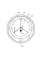
図1を参照すると、分配装置1が示さる。この分配装置1は、軸方向の注入開口11を有する円筒形状の分配チャンバ10を備える。分配チャンバ10はチャンバ内部空間12を有し、このチャンバ内部空間12内に、注入開口11が前方前壁15を貫通する。
Referring to FIG. 1, a distribution device 1 is shown. The dispensing device 1 comprises a cylindrical dispensing chamber 10 having an
分配チャンバ10は円筒形状の構成を有し、円筒形状の側壁13を有する。固体のための排出開口(図示せず)は、この側壁13の下部セグメントに配置される。
The distribution chamber 10 has a cylindrical configuration and has a
分配チャンバの前方前壁15は複数の接続ポート16a,16b,16c,・・・を有する。これら接続ポート16a,16b,16c,・・・は、チャンバ内部空間から離れる方向を向く前壁15の側部上の複数の管フランジとして具現化される。複数のホースは、分配チャンバから分配された固体混入液体を複数のホースに分配および送出するために、これらの接続ポート16a,16b,16c,・・・上に差し込まれることができる。
The front
前壁15と反対側の後方前壁17は、注入開口を例外として前方前壁15と一致するように具現化され、また複数の排出ポート18a,18b,18c,・・・を有する。
The rear
複数の接続ポート16a,16b,16c,・・・および18a,18b,18c,・・・は円形経路上に配置される。この円形経路は、ドライブシャフト軸100上にある中央点を有する。
A plurality of
複数のカッティング開口20a,20b,・・・および21a,21b,・・・は、前壁15および17における各接続ポートへの複数の接続ポート16a,16b,16c,・・・と重なるように配置される。これらのカッティング開口を通して、固体混入液体は、チャンバ内部空間12から出て、そして複数の接続ポート16a,16b,16c,・・・および18a,18b,18c,・・・の中に入ることができる。
The plurality of cutting
ブレードドライブシャフト30はチャンバ内部空間12に配置されて、後方前壁17における軸受け開口を貫通して延在し、ドライブシャフト軸100の周りを回転可能にそこに装着される。
A
偏心部40は、前方前壁15に隣接するチャンバ内部空間においてドライブシャフトに取り付けられる。偏心部40は、第1の偏心軸101を定義する。偏心軸101は、ドライブシャフト軸100に対して偏心度「e」を有する。第1のカッティングブレード50および第2のカッティングブレード70は、偏心部40上の転がり軸受けまたは滑り軸受け(図示せず)の手段によって、偏心軸101の周りを回転可能に装着される。偏心軸101は、転がり軸受けまたは滑り軸受けと、偏心部40の周りのカッティングブレード50,70の回転軸を表す。
The eccentric 40 is attached to the drive shaft in the chamber interior space adjacent to the front
ドライブシャフト30は、質量中心がドライブシャフト軸100に対して量rだけ偏心して配置される釣り合い重り35と連結される。釣り合い重り35の質量中心は、偏心軸101に関して180度だけオフセットされる。釣り合い重り35の距離rおよび質量は、偏心部40およびそこに取り付けられた偏心して移動される部品の偏心度Eおよび質量に比較して、移動される質量の1次質量バランスがドライブシャフト軸100の周りで達成されるように、寸法がとられる。特に、液体の慣性力はまた、釣り合い重りの手段によって補償されることが可能である。
The
第1のカッティングブレード50は、チャンバ内部空間の方向を向く前方前壁15の内部壁に密着するように配置される外側カッティングエッジ52および内側カッティングエッジ53を有する。外側カッティングエッジ52および内側カッティングエッジ53はしたがって、前方前壁15において円形に配置された複数のカッティング開口の開口20a,20bの複数のエッジと協働して、カッティングブレード50が動くときにこれら排出開口を通過する固体に対して剪断作用をもたらす。
The
同様に、第2のカッティングブレード70の外側カッティングエッジ72および内側カッティングエッジ73は後方前壁17の内部壁面に接して配置されて、カッティングブレード70が後方前壁17に対して相対的に移動するときに開口21a,21b,・・・の複数のカッティングエッジと協働する。
Similarly, the
ドライブシャフト30は、ブレードドライブシャフトを回転させる駆動モータ80と、チャンバ内部空間に対して外向きに連結する。これによって、ブレードドライブシャフトが回転され、また結果として、偏心部40がドライブシャフト軸の周りを回転できる。偏心軸101の周りのカッティングブレード50,70の受動的な回転実現性の結果として、これらのカッティングブレードは、前壁15および17の内面上のラッピングプロセスの方法で、移動を行う。
The
液体バッフル90は偏心部40に取り付けられ、偏心を伴って移動する。液体バッフル90は、注入開口11に向かう方向を向いている中央隆起領域91を有する。この隆起領域91をはじめとして、液体バッフル90は、軸方向92aから半径方向92bに延びる湾曲面92を有する。
The liquid baffle 90 is attached to the
液体バッフルは、注入開口11を通って入る液体を、流れのその軸方向から、流れの半径方向に偏向させる。したがって液体バッフルは、液体を、複数の排出開口20a,20b,・・・および21a,21b,・・・に一様に案内する。この偏向は、偏心運動によって開かれ且つカッティングブレード50,70によって閉じられないこれらの排出開口に対して、より強い強度で行われる。これは、なぜならば、液体バッフル90が偏心部とともに移動して、隆起領域91がそれ故に円形経路上の注入開口に対して偏心して旋回して、ドライブシャフト軸100に関して開放する複数の排出開口の反対側にそれぞれ位置付けられるために、達成される。
The liquid baffle deflects liquid entering through the inlet opening 11 from its axial direction in the flow to the radial direction of the flow. Therefore, the liquid baffle uniformly guides the liquid to the plurality of
チャンバ内部空間12は、液体バッフル90および環形状壁セグメント40aによって、液体案内空間12aと、第1の気体案内空間12bと、第2の気体案内空間12cと、に分けられる。当該環形状壁セグメント40aは、注入開口11および偏心部40上に配置される環形状壁セグメント40aの領域において配置され、また封止部材においてスライドするそこに沿って環形状壁セグメント15a上に移動される。
The chamber interior space 12 is divided by the liquid baffle 90 and the annular wall segment 40a into a
気体案内空間12bは、前方前壁15に接して配置されるカッティングブレード50に隣接して設けられる。吸気ポート11aは、外気が気体案内空間12bに入ることを可能にする。示される偏心配置において、この外気は、気体案内空間12bを通って排出開口16aに案内される。
The gas guide space 12b is provided adjacent to a
同様に鏡像反転された方法で、吸気ポート11bは前壁17に配置される。当該吸気ポート11bは、空気が気体案内空間12cに入ることを可能にし、また、空気が、図示される偏心位置における排出開口21aと接続ポート18aを通って案内されることを可能にする。
Similarly, the intake port 11b is arranged on the
カッティングブレード50,70は、複数の排出開口20a,20b,・・・および21a,21b,・・・の直径よりも小さい断面幅を有する。したがって、偏心運動の各時点において、複数の排出開口20a,20b,・・・および21a,21b,・・・が、チャンバ内部空間の液体案内セグメント12aと流体連通するか、気体案内セグメント12bおよび12cと流体連通するか、のいずれかが達成される。この常に存在する流体連通は、排出開口20a,20b,・・・および21a,21b,・・・のうちの1つが開放するときに液体が複数の排出開口を通過することを可能にする。したがって、この常に存在する流体連通は、複数の接続ポート16a,16b,・・・および18a,18b,・・・において移動する液柱を生成して、カッティングブレードが偏心運動の結果として移動し続けるときに複数の排出開口20a,20b,・・・および21a,21b,・・・の閉鎖によって唐突に減速されることなく、むしろ通気によって液体の入口の閉鎖の後に妨げられずに移動し続けることが可能である。結果として、複数の接続ポート16a,18a、およびこれらに接続されたホースまたはパイプラインを通る液体/気体混合物の、実質的に一定で加速度がない移動が達成されるとともに、分配装置内の封止部材および部品が高い機械的負荷と水圧パルス負荷にさらされることから保護される。
The
図2は、図1に係る実施形態の模式的な断面図を示す。図2に示すように、偏心位置において、偏心部はドライブシャフト軸に対して12時の位置にあり、最下部の注入開口21bは完全に開放されており、また最上部の注入開口21aは完全に閉鎖されている。他の複数の開口は、小さな度合いで閉鎖され(4時および8時の開口)、半分閉鎖され(3時および9時の開口)、また部分的に開放される(11時および1時)。カッティングブレード70の偏心運動の間、この開放状況は連続的且つ継続した方法で変化する。
FIG. 2 shows a schematic sectional view of the embodiment according to FIG. As shown in FIG. 2, in the eccentric position, the eccentric portion is located at 12 o'clock with respect to the drive shaft axis, the lowermost injection opening 21b is completely open, and the
図3は、本発明の第2の実施形態の図1に係る図を示す。本発明の第2の実施形態は多くの部分で第1の実施形態に対応する。以下においては、その差異に関してのみ説明する。 FIG. 3 shows a diagram according to FIG. 1 of a second embodiment of the invention. The second embodiment of the present invention largely corresponds to the first embodiment. In the following, only the differences will be described.
第2の実施形態において、固体含有液体はまた、注入路119の下位の流れの方向に位置する注入開口111を通して供給される。注入路119は、ドライブシャフト軸100に関連して軸方向に配置され、液体は注入路119を軸方向に通って円筒形状のチャンバ内部空間112内に流れる。
In a second embodiment, the solids-containing liquid is also supplied through an injection opening 111 located in the direction of flow below injection channel 119. The injection channel 119 is arranged axially with respect to the
ノズル195は注入路119に配置される。このノズル195は、注入路119において、断面の狭まりとそれに続く断面の拡大とをもたらす。結果として、液体はまず狭まる断面195aの領域において加速され、拡大する断面195bの領域において結局再びただ減速される。この加速と減速は液体の流れの方向の均質化をもたらし、それによって液体は、流れの近似的に軸方向にチャンバ内部空間112に入る。このさらなる開発の結果として、第2の実施形態は、制限されたスペースにおいても本発明に係る分配装置の運転を可能とするために、固体含有液体のための接続された供給ホースの顕著な湾曲と連携する注入路119への接続の方法の影響を受けない。
The nozzle 195 is disposed in the injection path 119. This nozzle 195 causes a narrowing of the cross section and a subsequent enlarging of the cross section in the injection path 119. As a result, the liquid is first accelerated in the region of the narrowing
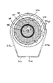
図4および5を参照し、本発明に係る分配装置の第3の実施形態が示される。本分配装置は、注入開口211を有する分配チャンバ210を備える。分配チャンバ210はチャンバ内部空間212を有し、このチャンバ内部空間212に注入開口211が通じる。
With reference to FIGS. 4 and 5, a third embodiment of the dispensing device according to the invention is shown. The dispensing device comprises a dispensing
分配チャンバ210は上側部分において円筒形状構造を有し、標準的な壁形状を有する台形断面に下方に延びる。固体のための排出開口214は下部ハウジング床面213に配置される。この排出開口214は、分配チャンバの上側領域における注入開口211の反対側に配置される。
The dispensing
分配チャンバの前方前壁215は、複数の接続ポート216a,216b、216c,・・・を有する。これら接続ポート216a,216b、216c,・・・は、チャンバ内部空間から離れる方向を向く前壁215の側部上の複数の管フランジとして具現化される。複数のホースは、分配チャンバから分配された固体混入液体を複数のホースに分配および送出するために、これらの接続ポート216に差し込まれることができる。
The front
前壁215と反対側の後方前壁217は、前方前壁215と一致するように具現化され、また、複数の排出ポート218a,218b,218c,・・・を有する。
A rear
複数の接続ポート216a,216b,216c,・・・および218a,218b,218c,・・・は円形経路上に配置される。この円形経路は、ドライブシャフト軸100上にある中央点を有する。
A plurality of connection ports 216a, 216b, 216c, ... and 218a, 218b, 218c, ... are arranged on a circular path. This circular path has a central point on the
前壁215および217における各接続ポートへの複数のカッティング開口220aおよび221aは、複数の接続ポート216a,216b,216c,・・・と重なるように配置される。これらのカッティング開口の結果として、固体混入液体はチャンバ内部空間212から複数の接続ポート216a,216b,216c,・・・および218a,218b,218c,・・・の中に入ることができる。
The plurality of cutting
ブレードドライブシャフト230はチャンバ内部空間212に配置されて、これは前壁215,217の軸受け開口を通って両側に延在し、ドライブシャフト軸の周りを回転可能にそこに配置される。
The
第1の偏心部240は、前方前壁215に隣接するチャンバ内部空間においてドライブシャフトに取り付けられ、当該第1の偏心部240上に、第1のカッティングブレード250は、転がり軸受け251の手段によって、回転可能に装着される。第1の偏心部240は、第1の偏心軸201を定義する。偏心軸201は、偏心部240の周りの転がり軸受け251とカッティングブレード250の回転軸を表す。それと反対側において、第2の偏心部260は、後方前壁217に隣接するチャンバ内部空間においてブレードドライブシャフトに取り付けられ、第2の偏心部260は、第2の偏心軸202を定義する。第2の偏心軸202は、第1の偏心軸201と同じ距離だけドライブシャフト軸100から離れた位置にあるが、ドライブシャフト軸100の周りを第1の偏心軸201に対して180度だけオフセットされる。
The first eccentric 240 is attached to the drive shaft in the chamber interior space adjacent to the front
第2のカッティングブレード70は、転がり軸受け271の手段によって、第2の偏心部260上に、第2の偏心軸202の周りを回転可能に装着される。転がり軸受け251,271に替えて、滑り軸受けが配置されることができる。
The
第1のカッティングブレード250は、チャンバ内部空間の方向を向く前方前壁215の内部壁に密着するように配置される外側カッティングエッジおよび内側カッティングエッジを有する。外側カッティングエッジ252および内側カッティングエッジ253はしたがって、前方前面板において円形に配置された複数のカッティング開口の開口220a,220bのエッジと協働して、カッティングブレード250が移動するときにこれら排出開口を通過する固体に対して剪断作用をもたらす。
The
同様に、外側カッティングエッジ272および内側カッティングエッジ273は後方前壁217の内部壁面に接して配置されて、カッティングブレード270が後方前壁217に対して相対的に移動するときに複数の開口221a,・・・のカッティングエッジと協働する。
Similarly, the
ドライブシャフト230は、ブレードドライブシャフトを回転させる駆動モータ280と、チャンバ内部空間に対して外向きに連結され、また結果として、偏心部240,260がドライブシャフト軸の周りを回転できる。
The
図6a〜図6dは、図5におけるA−A断面に係る断面表現における偏心運動の概要を示す。図6a〜図6dに示すように、排出開口220a,220b,220cのいくつかはカッティングブレード250によって閉鎖され、排出開口220a,220b,220c,・・・の他のいくつかは部分的に閉鎖され、排出開口220a,220b,220c,・・・の他のいくつかは閉鎖されていない。ドライブシャフト軸200の周りのカッティングブレードの図示される偏心した回転運動の結果として、全ての排出開口はその上をカッティングブレードによってスイープされ、それによって、排出開口220a,220b,220cの複数のエッジと協働して固体に対するカッティング効果が達成され、また、複数の排出開口が交互に開放および閉鎖され、したがって液体の通過が可能となる。
6a to 6d show the outline of the eccentric movement in the cross-sectional expression along the AA cross section in FIG. As shown in FIGS. 6a to 6d, some of the
図7は、本発明に係る分配装置の第4の実施形態の縦断面図を示す。図7および8に係る実施形態は、小さな偏心度と大きな偏心度との間で偏心軸の偏心度を調整できる調整機構によって、特徴付けられる。 FIG. 7 shows a longitudinal section of a fourth embodiment of the dispensing device according to the invention. The embodiment according to FIGS. 7 and 8 is characterized by an adjusting mechanism that can adjust the eccentricity of the eccentric shaft between a small eccentricity and a large eccentricity.
前述の複数の実施形態と同様に、図7および8に係る分配装置は分配チャンバハウジング310を有し、当該分配チャンバハウジング310に注入開口(図示せず)が配置され、当該注入開口は上方から、この第4の実施形態における分配チャンバ内に通じる。前側において、分配チャンバは、前壁315,317によって閉じられている。これら前壁315,317において、いくつかの円形に配置された排出開口320a,320bおよび321a,321bが配置され、これら排出開口320a,320bおよび321a,321bは複数の排出ポート316a,316bおよび318a,318bに重なるようにつながる。
As in the previous embodiments, the dispensing device according to FIGS. 7 and 8 has a dispensing
固体のための排出開口314は床板313に配置され、メンテナンス用開口313a,313bは側壁を下方に円錐形に覆うように存在し、このメンテナンス用開口313a,313bを通して分配チャンバの内部空間にアクセスすることが可能である。
The
第1の偏心部340および第2の偏心部360は分配チャンバに配置される。第1の偏心部は第1の偏心軸301を定義し、第2の偏心部は第2の偏心軸302を定義し、第2の偏心軸302は、ドライブシャフト軸300に関して第1の偏心軸301に対して180度だけオフセットされる。偏心部340,360はしたがって、互いに180度だけ位相シフトされて移動し(上述のように、位相シフトは新たな実施形態において働かない。)、したがって、ドライブシャフト軸300の周りの1次質量バランスが得られる。
The first eccentric 340 and the second eccentric 360 are located in the distribution chamber. The first eccentric defines a first
カッティングブレード350は、転がり軸受け351の手段によって、第1の偏心部340上に回転可能に取り付けられる。これに類似して、カッティングブレード370は、転がり軸受け371の手段によって、第2の偏心部360上に回転可能に装着される。
The
偏心部340,360は、カム382,383の手段によって、駆動モータ380の駆動ジャーナル381と連結される。カム382,383はそれぞれ、六角形ロッド384が貫通する六角形形状の孔を有する。
The
カム383は、はめ込みの手段によって耐トルクの方法で、駆動ジャーナル381に接続される。このカム382からのトルクは、六角形ロッド384を介して、カム383に伝達される。カム382は、転がり軸受けまたは滑り軸受けの手段によってドライブシャフト軸の周りを回転可能に装着され、ここで、円筒形状の滑り軸受けおよび転がり軸受けは軸受けハウジング315aにある。
The
駆動モータ380は時計回りの方向に駆動し(図8に係る図示において、偏心部360の反時計回りの回転に対応する)、カム383は図8に示す位置にあると仮定する。この位置において、偏心軸302は、ドライブシャフト軸300に対する第1の偏心度を有する。
駆動モータ380の回転方向が反転されて駆動モータが反時計回りの方向に運転されると、カム383は、偏心部360におけるL字形状凹部361内で、第2の回り止め位置まで旋回する。六角形ロッドが通るカム383のセグメントは、図8に示す凹部361の空き空間を通過してその中に移動し、図8に係る図示において、カムは時計回りの方向に90度の旋回運動を行う。この旋回運動の後に生じるドライブシャフト軸300に対する偏心軸301の偏心度は、第1の偏心度よりも大きく、それによって、カッティングブレード370はより大きな偏心度で経路上をガイドされる。
When the rotation direction of the
同様のしかし中央断面に関して鏡像反転された構成において、対応する駆動は、第1の偏心部340におけるカム382によっても達成され、また、小さな偏心度と大きな偏心度との間の切り換えはモータ380の回転方向の反転を用いて達成される。
In a similar but mirror-inverted configuration with respect to the central section, a corresponding drive is also achieved by the
偏心部340,360における凹部361,341およびカム382,383の配置は、偏心部340,360の両方がドライブシャフト軸300に対する一致した偏心度を有して常に位置されるように、選択される。
The arrangement of the
小さな偏心度と大きな偏心度との間の切り換えの実現性によって、図7および8に係る実施形態において、分配装置において低いスループットと高いスループットを達成することを可能とすることができる。小さな偏心度の場合において、前壁315および317に隣接して配置される有孔ブレードディスク355,375における複数のスループット開口は、図8に示すように、常に部分的にまたは完全に閉鎖される。
The feasibility of switching between small and large eccentricities can make it possible in the embodiments according to FIGS. 7 and 8 to achieve low and high throughputs in the distribution device. In the case of small eccentricity, the plurality of throughput openings in
対照的に、大きな偏心度の場合において、有孔ブレードディスクにおけるこれらの開口は、偏心軸の反対側の領域において完全に開放され、偏心軸の側において完全に閉鎖され、偏心軸の横方向の領域において部分的に開放される。したがって結果として、分配チャンバにおける一定の内圧で複数の開口を通して、液体の全体としてより多くの送出が可能となる。例えば遠心ポンプなどの圧力ポンプの後段で、またはコンプレッサタンクカート上で分配装置を使用するとき、分配装置を通過する体積流量は、結果として直ちに増加する。排出ポンプの後段で分配装置を使用する場合、偏心度の調整時に、異なるハウジング圧力が生じ得る。そして、排出ポンプの動作点は、増加されたスループットに適合される必要がある場合があり、または、分配装置は、ディスプレイメントポンプの異なる複数の体積流量に適合されることができる。 In contrast, in the case of large eccentricity, these openings in the perforated blade disk are completely open in the area opposite the eccentric axis, completely closed on the side of the eccentric axis, and transverse to the eccentric axis. Partially open in the area. Thus, as a result, a greater overall delivery of liquid is possible through a plurality of openings at a constant internal pressure in the distribution chamber. When using a dispensing device downstream of a pressure pump, for example a centrifugal pump, or on a compressor tank cart, the volume flow through the dispensing device is immediately increased as a result. If the distributor is used downstream of the discharge pump, different housing pressures can occur when adjusting the eccentricity. And the operating point of the evacuation pump may need to be adapted to the increased throughput, or the dispenser may be adapted to different volume flows of the displacement pump.
図9は、凹部361におけるカム383の調整機構の運動を示す。図9に示すように、カムは、偏心軸302とドライブシャフト軸300との間の低い偏心度Aを有する第1の位置にあると仮定することができる。カムは、回転方向の反転時に凹部内で回転して90度の旋回運動を行うことによって、第2の位置に旋回する。その後、カムは、凹部の以前空いていたセグメントに移動して留まる。この第2の位置において、カムはまたトルクの確実な伝達のために凹部に配置されて、今度は偏心度Aよりも大きな偏心軸302とドライブシャフト軸300との間の第2の偏心度Bを有する。
FIG. 9 shows the movement of the adjusting mechanism of the
Claims (24)
前記チャンバ内部空間をいくつかの接続ポートに接続するいくつかの排出開口を有する第1の有孔ブレードディスクと、
ドライブシャフト軸の周りを旋回可能に装着されたブレードドライブシャフトと、を備え、
前記ブレードドライブシャフトに接続され、前記ドライブシャフト軸から離間された第1の偏心軸が定義される第1の偏心部材と、
前記第1の偏心部材に接続され、前記第1の有孔ブレードディスクに接して配置されるカッティングエッジを有し、前記第1の偏心部材の手段によって前記第1の有孔ブレードディスクに対して相対的に移動可能である第1のカッティングブレードと、
によって特徴付けられ、
更に、釣り合い重り部材は前記ブレードドライブシャフトに接続され、その質量中心は前記ドライブシャフト軸に対して偏心して配置される
ことによって特徴付けられる、液体のための分配装置。 A dispensing chamber having an injection opening communicating with the chamber interior space of the dispensing chamber;
A first perforated blade disc having a number of discharge openings connecting said chamber interior space to a number of connection ports;
A blade drive shaft mounted to be pivotable about the drive shaft axis,
A first eccentric member connected to the blade drive shaft and defining a first eccentric axis spaced from the drive shaft axis;
A cutting edge connected to the first eccentric member and disposed in contact with the first perforated blade disk, and having a cutting edge relative to the first perforated blade disk by means of the first eccentric member; A first cutting blade that is relatively movable;
Characterized by
Furthermore, a dispensing device for liquid, characterized in that a counterweight is connected to the blade drive shaft, the center of mass of which is arranged eccentrically with respect to the drive shaft axis.
によって特徴付けられる、請求項1記載の分配装置。 Connecting the first eccentric member to the blade drive shaft and, at a first detent position on the first eccentric member, moving the first eccentric member to the first eccentric axis relative to the drive shaft axis; The drive shaft axle positioned at a second detent position on the first eccentric member, wherein the first eccentric member is greater than the first eccentricity at a second detent position on the first eccentric member. The dispensing device according to claim 1, characterized by a coupling member positioned to have a second degree of eccentricity of the first eccentric axis with respect to the first eccentric axis.
ことを特徴とする、請求項2記載の分配装置。 The connecting member, the rotation direction of the reversing means of the blade drive shaft, is reciprocated between the first detent position and the second detent position,
3. The dispensing device according to claim 2, wherein:
ことを特徴とする、請求項2または3記載の分配装置。 The connecting member securely engages with the concave portion of the first eccentric member;
A dispensing device according to claim 2 or 3, characterized in that:
前記凹部は、前記ブレードドライブシャフトの第1の回転方向への前記カムのための第1の回り止め位置と、前記第1の回転方向と反対方向である前記ブレードドライブシャフトの回転方向への第2の回り止め位置と、を提供する、
ことを特徴とする、請求項4記載の分配装置。 The connecting member includes a cam that engages with the concave portion of the first eccentric member;
The recess has a first detent position for the cam in a first rotational direction of the blade drive shaft and a second detent in a rotational direction of the blade drive shaft that is opposite to the first rotational direction. Providing two detent positions,
The dispensing device according to claim 4, characterized in that:
ことを特徴とする、請求項2〜5のうちのいずれか一項記載の分配装置。 The connection member and the blade drive shaft are integrally embodied;
A dispensing device according to any one of claims 2 to 5, characterized in that:
第2のカッティングブレードは提供され、当該第2のカッティングブレードは、前記第2の有孔ブレードディスクに接して配置され且つそれに対して相対的に移動可能であるカッティングエッジを有する、
ことを特徴とする、請求項2〜6のうちのいずれか一項記載の分配装置。 A second perforated blade disk having a number of discharge openings bounds a chamber interior space of the distribution chamber;
A second cutting blade is provided, wherein the second cutting blade has a cutting edge disposed against and movable relative to the second perforated blade disc.
The dispensing device according to any one of claims 2 to 6, characterized in that:
前記第2のカッティングブレードのカッティングエッジは、前記第1の偏心部材の手段によって、前記第2の有孔ブレードディスクに対して相対的に移動可能である、
ことを特徴とする、請求項7記載の分配装置。 The second cutting blade is connected to the first eccentric member;
The cutting edge of the second cutting blade is movable relative to the second perforated blade disk by means of the first eccentric member;
The dispensing device according to claim 7, characterized in that:
ことを特徴とする、請求項7または8記載の分配装置。 The first and / or second cutting blades are mounted on the first eccentric member so as to be rotatable about the first eccentric axis;
The dispensing device according to claim 7 or 8, wherein:
ことを特徴とする、請求項1〜9のうちのいずれか一項記載の分配装置。 The counterweight is connected to the blade drive shaft, the center of mass of which is disposed offset by 180 degrees with respect to the first eccentric axis ;
A dispensing device according to any one of the preceding claims, characterized in that:
ことを特徴とする、請求項1〜10のうちのいずれか一項記載の分配装置。 The injection opening defines a direction in which the solid-containing liquid is injected, which is parallel to the drive shaft axis.
A dispensing device according to any of the preceding claims, characterized in that:
ことを特徴とする、請求項1〜10のうちのいずれか一項記載の分配装置。 The injection opening is coaxial with the drive shaft axis, and defines an injection direction of the solid-containing liquid.
A dispensing device according to any of the preceding claims, characterized in that:
ことを特徴とする、請求項11または12記載の分配装置。 A liquid control system is disposed in the chamber interior space, the liquid control system having a shape in which liquid flowing in an axial direction is deflected radially outward there;
13. The dispensing device according to claim 11, wherein:
流れの方向において、当該流路に配置される縮小される断面およびこれに続く増大される断面を有するノズルと、
によって特徴付けられる、請求項1〜13のうちのいずれか一項記載の分配装置。 A flow path in the direction of flow, upstream from the injection opening in the chamber interior space;
A nozzle having a reduced cross section followed by an increased cross section disposed in the flow path in the direction of flow;
14. The dispensing device according to any one of the preceding claims, characterized by:
ことを特徴とする、請求項7記載の分配装置。 The second cutting blade is connected to a second eccentric member;
The dispensing device according to claim 7, characterized in that:
ことを特徴とする、請求項15記載の分配装置。 The second eccentric member is connected to the blade drive shaft and defines a second eccentric axis that is spaced apart from the drive shaft axis, wherein the second eccentric axis is in communication with the first eccentric axis . Do not extend coaxially,
The dispensing device according to claim 15, characterized in that:
ことを特徴とする、請求項16記載の分配装置。 The second cutting blade is rotatably mounted on the second eccentric member about the second eccentric axis;
17. The dispensing device according to claim 16, wherein:
前記第2の偏心部材上の第1の回り止め位置において、前記第2の偏心部材は、前記ドライブシャフト軸に対する前記第2の偏心軸の第1の偏心度を有するように位置付けられ、
前記第2の偏心部材上の第2の回り止め位置において、前記第2の偏心部材は、前記第1の偏心度よりも大きい、前記ドライブシャフト軸に対する前記第2の偏心軸の第2の偏心度を有するように位置付けられる、
ことを特徴とする、請求項16〜17のうちのいずれか一項記載の分配装置。 The connecting member is engaged with a concave portion of the second eccentric member,
In a first detent position on the second eccentric member, the second eccentric member is positioned to have a first degree of eccentricity of the second eccentric axis with respect to the drive shaft axis;
In a second detent position on the second eccentric member, the second eccentric member has a second eccentricity of the second eccentric shaft with respect to the drive shaft axis that is greater than the first eccentricity. Positioned to have a degree,
The dispensing device according to any one of claims 16 to 17, characterized in that:
ことを特徴とする、請求項16〜18のうちのいずれか一項記載の分配装置。 The second eccentric axis is offset about the drive shaft axis with respect to the first eccentric axis;
A dispensing device according to any one of claims 16 to 18, characterized in that:
ことを特徴とする、請求項16〜18のうちのいずれか一項記載の分配装置。 The second eccentric axis is offset by 180 degrees about the drive shaft axis with respect to the first eccentric axis;
A dispensing device according to any one of claims 16 to 18, characterized in that:
前記第2の凹部は、前記ブレードドライブシャフトの第1の回転方向への前記第2のカムのための第1の回り止め位置と、前記第1の回転方向と反対方向である前記ブレードドライブシャフトの回転方向への第2の回り止め位置と、を提供する、
ことを特徴とする、請求項5、8〜20のうちのいずれか一項記載の分配装置。 A second cam is engaged with a second recess of the first eccentric member,
The second recess is a first detent position for the second cam in a first rotational direction of the blade drive shaft; and the blade drive shaft is in a direction opposite to the first rotational direction. A second detent position in the direction of rotation of the
The dispensing device according to any one of claims 5, 8 to 20, characterized in that:
ことを特徴とする、請求項7記載の分配装置。 Wherein the first and / or second cutting blade has a circular ring shape, has at least one circumferential cutting edge is arranged in contact with the first or second perforated blade disc, Embodied on the inner and outer edges of the first or second cutting blade,
The dispensing device according to claim 7, characterized in that:
前記ドライブシャフト軸に対する前記第1および/または第2の偏心軸の距離、および外側カッティングエッジの直径は、前記外側カッティングエッジが、前記通気開口が通じる面を取り囲む偏心経路上を、移動するように選択され、
前記第1および/または第2のカッティングブレードの前記内側エッジと前記外側エッジとの間の距離は、前記第1または第2の有孔ブレードディスクにおける前記複数の排出開口の直径よりも小さいまたはこれに等しい、
ことを特徴とする、請求項22記載の分配装置。 A vent opening present in said first or second perforated blade disk, said vent opening communicating with a space represented by an inner cutting edge of said first and / or second cutting blade;
The drive said relative shaft axis first and / or the length of the second eccentric shaft, and the outer cutting edge diameter, the outer cutting edge, the upper eccentric path surrounding the vent opening leading face, so as to move Selected,
A distance between the inner edge and the outer edge of the first and / or second cutting blade is less than or equal to a diameter of the plurality of discharge openings in the first or second perforated blade disk; be equivalent to,
A dispensing device according to claim 22, characterized in that:
前記カムおよび前記第2のカムは、前記第1の回り止め位置において前記凹部および前記第2の凹部の第1のアームに接して配置され、前記第2の回り止め位置において前記凹部および前記第2の凹部の第2のアームに接して配置される、
ことを特徴とする、請求項21記載の分配装置。 The concave portion and the second concave portion have a rounded L-shape,
The cam and the second cam are arranged in contact with the first arm of the concave portion and the second concave portion at the first detent position, and the concave portion and the second portion at the second detent position . Arranged in contact with the second arm of the second recess ,
A dispensing device according to claim 21 , characterized in that:
Applications Claiming Priority (2)
| Application Number | Priority Date | Filing Date | Title |
|---|---|---|---|
| DE202013008267.4 | 2013-09-19 | ||
| DE202013008267.4U DE202013008267U1 (en) | 2013-09-19 | 2013-09-19 | Distributor for solids containing liquids |
Publications (3)
| Publication Number | Publication Date |
|---|---|
| JP2015072066A JP2015072066A (en) | 2015-04-16 |
| JP2015072066A5 JP2015072066A5 (en) | 2017-11-02 |
| JP6667988B2 true JP6667988B2 (en) | 2020-03-18 |
Family
ID=51618994
Family Applications (1)
| Application Number | Title | Priority Date | Filing Date |
|---|---|---|---|
| JP2014191704A Expired - Fee Related JP6667988B2 (en) | 2013-09-19 | 2014-09-19 | Dispensing device for liquids containing solids |
Country Status (12)
| Country | Link |
|---|---|
| US (1) | US9833786B2 (en) |
| EP (1) | EP2850928B1 (en) |
| JP (1) | JP6667988B2 (en) |
| CA (1) | CA2863716C (en) |
| DE (1) | DE202013008267U1 (en) |
| DK (1) | DK2850928T3 (en) |
| ES (1) | ES2660885T3 (en) |
| NO (1) | NO3044785T3 (en) |
| NZ (1) | NZ700200A (en) |
| PL (1) | PL2850928T3 (en) |
| PT (1) | PT2850928T (en) |
| TR (1) | TR201802925T4 (en) |
Families Citing this family (12)
| Publication number | Priority date | Publication date | Assignee | Title |
|---|---|---|---|---|
| DK178936B1 (en) * | 2014-08-28 | 2017-06-12 | Harry Højvang Sørensen | SLURRY DISTRIBUTOR |
| DE102015121039A1 (en) * | 2015-12-03 | 2017-06-08 | Bomech B.V. | Distribution device, fertilizer device and method for distributing liquid substances |
| DE202016102246U1 (en) | 2016-04-27 | 2017-07-28 | Hugo Vogelsang Maschinenbau Gmbh | Sanitary facility with extractable waste water tank |
| US11084071B2 (en) | 2017-02-24 | 2021-08-10 | Vogelsang Gmbh & Co Kg | Suction device for wastewater tank and disposal station for a vehicle |
| DE202017104786U1 (en) * | 2017-08-09 | 2018-11-12 | Vogelsang Gmbh & Co. Kg | Distributor device for solids containing liquids |
| WO2019049120A1 (en) * | 2017-09-05 | 2019-03-14 | Mastek Limited | A macerator |
| CN109530040B (en) * | 2018-12-05 | 2023-08-15 | 温州大学 | Cutting tool module and fluid crushing device |
| DE202018107208U1 (en) | 2018-12-17 | 2020-03-20 | Vogelsang Gmbh & Co. Kg | Distribution device for solids-carrying liquids |
| CN109644621B (en) * | 2019-01-21 | 2020-10-16 | 杨克伟 | Agricultural seeding fertilization watering integration equipment |
| DE102019215135A1 (en) * | 2019-10-01 | 2021-04-01 | Röhren- Und Pumpenwerk Bauer Ges.M.B.H. | Distribution device for a pulp |
| DE202020107208U1 (en) | 2020-12-14 | 2022-03-15 | Vogelsang Gmbh & Co. Kg | Distribution device for distributing liquids containing solids |
| DE202021102511U1 (en) | 2021-05-07 | 2022-08-11 | Vogelsang Gmbh & Co. Kg | Distribution device with adjustable passage cross-section |
Family Cites Families (5)
| Publication number | Priority date | Publication date | Assignee | Title |
|---|---|---|---|---|
| JPS5297631U (en) * | 1976-01-22 | 1977-07-22 | ||
| DK170545B1 (en) * | 1993-08-09 | 1995-10-23 | Harry Soerensen | slurry spreaders |
| DE602005012355D1 (en) | 2004-11-12 | 2009-03-05 | Soerensen Harry H | Distribution unit and method for distributing liquids such as manure into the outlets of a manure spreader |
| DK176629B1 (en) * | 2006-10-23 | 2008-12-01 | Soerensen Harry H | Advantages of distributing a main stream of a liquid into a number of sub-streams |
| DE202011050654U1 (en) * | 2011-07-07 | 2011-10-19 | Stapel Gmbh | Distributor device for a solids-laden liquid |
-
2013
- 2013-09-19 DE DE202013008267.4U patent/DE202013008267U1/en not_active Expired - Lifetime
-
2014
- 2014-09-08 NO NO14761364A patent/NO3044785T3/no unknown
- 2014-09-17 CA CA2863716A patent/CA2863716C/en not_active Expired - Fee Related
- 2014-09-19 PL PL14185504T patent/PL2850928T3/en unknown
- 2014-09-19 JP JP2014191704A patent/JP6667988B2/en not_active Expired - Fee Related
- 2014-09-19 EP EP14185504.9A patent/EP2850928B1/en active Active
- 2014-09-19 PT PT141855049T patent/PT2850928T/en unknown
- 2014-09-19 DK DK14185504.9T patent/DK2850928T3/en active
- 2014-09-19 TR TR2018/02925T patent/TR201802925T4/en unknown
- 2014-09-19 NZ NZ700200A patent/NZ700200A/en not_active IP Right Cessation
- 2014-09-19 US US14/490,757 patent/US9833786B2/en not_active Expired - Fee Related
- 2014-09-19 ES ES14185504.9T patent/ES2660885T3/en active Active
Also Published As
| Publication number | Publication date |
|---|---|
| DK2850928T3 (en) | 2018-02-26 |
| NZ700200A (en) | 2016-08-26 |
| PT2850928T (en) | 2018-03-01 |
| EP2850928A1 (en) | 2015-03-25 |
| EP2850928B1 (en) | 2017-12-20 |
| CA2863716C (en) | 2021-03-16 |
| CA2863716A1 (en) | 2015-03-19 |
| TR201802925T4 (en) | 2018-03-21 |
| PL2850928T3 (en) | 2018-05-30 |
| NO3044785T3 (en) | 2018-05-12 |
| DE202013008267U1 (en) | 2015-01-09 |
| ES2660885T3 (en) | 2018-03-26 |
| JP2015072066A (en) | 2015-04-16 |
| US20150076261A1 (en) | 2015-03-19 |
| US9833786B2 (en) | 2017-12-05 |
Similar Documents
| Publication | Publication Date | Title |
|---|---|---|
| JP6667988B2 (en) | Dispensing device for liquids containing solids | |
| JP3223933U (en) | Particle blasting equipment | |
| KR101924910B1 (en) | Dynamic mixer | |
| JP5166279B2 (en) | Device for spraying liquid | |
| US6360965B1 (en) | Fluid delivery from a spray head having a moving nozzle | |
| EP1492970B1 (en) | Valve assembly | |
| AU2012222608B2 (en) | Dynamic mixer and use thereof | |
| KR101842575B1 (en) | Shower head with rotatable control disk | |
| JPH04339796A (en) | Control of flow of fluid | |
| JP2015072066A5 (en) | ||
| WO2016042104A1 (en) | Assembly for and method of dispensing a liquid | |
| EP0825422A1 (en) | A metering device | |
| KR101858445B1 (en) | Paint discharging device for painging traffice lane | |
| US7083683B2 (en) | Apparatus for the formation of coverings on surfaces of solid bodies in a coating chamber | |
| WO2014047460A2 (en) | Fluid-dispensing nozzle | |
| JPH04249693A (en) | Rotary joint having directional control valve | |
| JP6388981B2 (en) | Dynamic mixer and method of mixing two components using dynamic mixer | |
| CN110193432A (en) | The dispensing head with step minor air cell for distribution system | |
| JP2015145627A (en) | Tube pump and gas/liquid two phase flow supplying device | |
| RU2240449C2 (en) | Pulsar (versions) | |
| KR20220013461A (en) | Rotary atomizer turbine | |
| WO2016067973A1 (en) | Seal device and rotary machine | |
| CN108138414A (en) | For handling the device of strand-like textile material |
Legal Events
| Date | Code | Title | Description |
|---|---|---|---|
| RD04 | Notification of resignation of power of attorney |
Free format text: JAPANESE INTERMEDIATE CODE: A7424 Effective date: 20150630 |
|
| A521 | Request for written amendment filed |
Free format text: JAPANESE INTERMEDIATE CODE: A523 Effective date: 20170914 |
|
| A621 | Written request for application examination |
Free format text: JAPANESE INTERMEDIATE CODE: A621 Effective date: 20170914 |
|
| A131 | Notification of reasons for refusal |
Free format text: JAPANESE INTERMEDIATE CODE: A131 Effective date: 20180717 |
|
| A977 | Report on retrieval |
Free format text: JAPANESE INTERMEDIATE CODE: A971007 Effective date: 20180719 |
|
| A521 | Request for written amendment filed |
Free format text: JAPANESE INTERMEDIATE CODE: A523 Effective date: 20181015 |
|
| A131 | Notification of reasons for refusal |
Free format text: JAPANESE INTERMEDIATE CODE: A131 Effective date: 20190226 |
|
| A521 | Request for written amendment filed |
Free format text: JAPANESE INTERMEDIATE CODE: A523 Effective date: 20190508 |
|
| RD03 | Notification of appointment of power of attorney |
Free format text: JAPANESE INTERMEDIATE CODE: A7423 Effective date: 20191007 |
|
| A131 | Notification of reasons for refusal |
Free format text: JAPANESE INTERMEDIATE CODE: A131 Effective date: 20191029 |
|
| A521 | Request for written amendment filed |
Free format text: JAPANESE INTERMEDIATE CODE: A523 Effective date: 20200121 |
|
| TRDD | Decision of grant or rejection written | ||
| A01 | Written decision to grant a patent or to grant a registration (utility model) |
Free format text: JAPANESE INTERMEDIATE CODE: A01 Effective date: 20200204 |
|
| A61 | First payment of annual fees (during grant procedure) |
Free format text: JAPANESE INTERMEDIATE CODE: A61 Effective date: 20200226 |
|
| R150 | Certificate of patent or registration of utility model |
Ref document number: 6667988 Country of ref document: JP Free format text: JAPANESE INTERMEDIATE CODE: R150 |
|
| LAPS | Cancellation because of no payment of annual fees |