JP6667514B2 - System and method for automatic single dose control in x-ray imaging - Google Patents
System and method for automatic single dose control in x-ray imaging Download PDFInfo
- Publication number
- JP6667514B2 JP6667514B2 JP2017517437A JP2017517437A JP6667514B2 JP 6667514 B2 JP6667514 B2 JP 6667514B2 JP 2017517437 A JP2017517437 A JP 2017517437A JP 2017517437 A JP2017517437 A JP 2017517437A JP 6667514 B2 JP6667514 B2 JP 6667514B2
- Authority
- JP
- Japan
- Prior art keywords
- image
- ray
- computer processor
- dimensional
- images
- Prior art date
- Legal status (The legal status is an assumption and is not a legal conclusion. Google has not performed a legal analysis and makes no representation as to the accuracy of the status listed.)
- Active
Links
- 238000003384 imaging method Methods 0.000 title claims description 122
- 238000000034 method Methods 0.000 title claims description 92
- 238000001914 filtration Methods 0.000 claims description 22
- 238000012545 processing Methods 0.000 claims description 5
- 230000000977 initiatory effect Effects 0.000 claims 1
- 230000009467 reduction Effects 0.000 description 24
- 239000003550 marker Substances 0.000 description 13
- 238000010586 diagram Methods 0.000 description 8
- 230000006870 function Effects 0.000 description 7
- 230000005855 radiation Effects 0.000 description 7
- 230000015654 memory Effects 0.000 description 5
- 230000000704 physical effect Effects 0.000 description 5
- 238000002591 computed tomography Methods 0.000 description 4
- 238000007408 cone-beam computed tomography Methods 0.000 description 3
- 238000005259 measurement Methods 0.000 description 3
- 238000005457 optimization Methods 0.000 description 3
- 238000003825 pressing Methods 0.000 description 3
- 230000008569 process Effects 0.000 description 3
- 210000003484 anatomy Anatomy 0.000 description 2
- 230000008901 benefit Effects 0.000 description 2
- 238000004364 calculation method Methods 0.000 description 2
- 238000009826 distribution Methods 0.000 description 2
- 238000013178 mathematical model Methods 0.000 description 2
- 238000012986 modification Methods 0.000 description 2
- 230000004048 modification Effects 0.000 description 2
- 238000012360 testing method Methods 0.000 description 2
- 238000012935 Averaging Methods 0.000 description 1
- 238000004458 analytical method Methods 0.000 description 1
- 230000001174 ascending effect Effects 0.000 description 1
- 230000008859 change Effects 0.000 description 1
- 238000004891 communication Methods 0.000 description 1
- 230000000052 comparative effect Effects 0.000 description 1
- 238000012790 confirmation Methods 0.000 description 1
- 238000012937 correction Methods 0.000 description 1
- 230000000694 effects Effects 0.000 description 1
- 238000011156 evaluation Methods 0.000 description 1
- 230000002349 favourable effect Effects 0.000 description 1
- 230000007246 mechanism Effects 0.000 description 1
- 238000012544 monitoring process Methods 0.000 description 1
- 210000000056 organ Anatomy 0.000 description 1
- 238000007781 pre-processing Methods 0.000 description 1
- 238000002360 preparation method Methods 0.000 description 1
- 238000012827 research and development Methods 0.000 description 1
- 210000003625 skull Anatomy 0.000 description 1
- 230000026676 system process Effects 0.000 description 1
- WFKWXMTUELFFGS-UHFFFAOYSA-N tungsten Chemical compound [W] WFKWXMTUELFFGS-UHFFFAOYSA-N 0.000 description 1
- 229910052721 tungsten Inorganic materials 0.000 description 1
- 239000010937 tungsten Substances 0.000 description 1
- 238000012795 verification Methods 0.000 description 1
- 239000002699 waste material Substances 0.000 description 1
Images


Classifications
-
- A—HUMAN NECESSITIES
- A61—MEDICAL OR VETERINARY SCIENCE; HYGIENE
- A61B—DIAGNOSIS; SURGERY; IDENTIFICATION
- A61B6/00—Apparatus for radiation diagnosis, e.g. combined with radiation therapy equipment
- A61B6/02—Devices for diagnosis sequentially in different planes; Stereoscopic radiation diagnosis
- A61B6/03—Computerised tomographs
- A61B6/032—Transmission computed tomography [CT]
-
- A—HUMAN NECESSITIES
- A61—MEDICAL OR VETERINARY SCIENCE; HYGIENE
- A61B—DIAGNOSIS; SURGERY; IDENTIFICATION
- A61B6/00—Apparatus for radiation diagnosis, e.g. combined with radiation therapy equipment
- A61B6/40—Apparatus for radiation diagnosis, e.g. combined with radiation therapy equipment with arrangements for generating radiation specially adapted for radiation diagnosis
- A61B6/4064—Apparatus for radiation diagnosis, e.g. combined with radiation therapy equipment with arrangements for generating radiation specially adapted for radiation diagnosis specially adapted for producing a particular type of beam
- A61B6/4085—Cone-beams
-
- A—HUMAN NECESSITIES
- A61—MEDICAL OR VETERINARY SCIENCE; HYGIENE
- A61B—DIAGNOSIS; SURGERY; IDENTIFICATION
- A61B6/00—Apparatus for radiation diagnosis, e.g. combined with radiation therapy equipment
- A61B6/46—Apparatus for radiation diagnosis, e.g. combined with radiation therapy equipment with special arrangements for interfacing with the operator or the patient
- A61B6/461—Displaying means of special interest
- A61B6/466—Displaying means of special interest adapted to display 3D data
-
- A—HUMAN NECESSITIES
- A61—MEDICAL OR VETERINARY SCIENCE; HYGIENE
- A61B—DIAGNOSIS; SURGERY; IDENTIFICATION
- A61B6/00—Apparatus for radiation diagnosis, e.g. combined with radiation therapy equipment
- A61B6/48—Diagnostic techniques
- A61B6/488—Diagnostic techniques involving pre-scan acquisition
-
- A61B6/51—
-
- A—HUMAN NECESSITIES
- A61—MEDICAL OR VETERINARY SCIENCE; HYGIENE
- A61B—DIAGNOSIS; SURGERY; IDENTIFICATION
- A61B6/00—Apparatus for radiation diagnosis, e.g. combined with radiation therapy equipment
- A61B6/52—Devices using data or image processing specially adapted for radiation diagnosis
- A61B6/5205—Devices using data or image processing specially adapted for radiation diagnosis involving processing of raw data to produce diagnostic data
-
- A—HUMAN NECESSITIES
- A61—MEDICAL OR VETERINARY SCIENCE; HYGIENE
- A61B—DIAGNOSIS; SURGERY; IDENTIFICATION
- A61B6/00—Apparatus for radiation diagnosis, e.g. combined with radiation therapy equipment
- A61B6/52—Devices using data or image processing specially adapted for radiation diagnosis
- A61B6/5211—Devices using data or image processing specially adapted for radiation diagnosis involving processing of medical diagnostic data
-
- A—HUMAN NECESSITIES
- A61—MEDICAL OR VETERINARY SCIENCE; HYGIENE
- A61B—DIAGNOSIS; SURGERY; IDENTIFICATION
- A61B6/00—Apparatus for radiation diagnosis, e.g. combined with radiation therapy equipment
- A61B6/52—Devices using data or image processing specially adapted for radiation diagnosis
- A61B6/5258—Devices using data or image processing specially adapted for radiation diagnosis involving detection or reduction of artifacts or noise
-
- A—HUMAN NECESSITIES
- A61—MEDICAL OR VETERINARY SCIENCE; HYGIENE
- A61B—DIAGNOSIS; SURGERY; IDENTIFICATION
- A61B6/00—Apparatus for radiation diagnosis, e.g. combined with radiation therapy equipment
- A61B6/54—Control of apparatus or devices for radiation diagnosis
- A61B6/542—Control of apparatus or devices for radiation diagnosis involving control of exposure
-
- G—PHYSICS
- G06—COMPUTING; CALCULATING OR COUNTING
- G06T—IMAGE DATA PROCESSING OR GENERATION, IN GENERAL
- G06T5/00—Image enhancement or restoration
-
- G—PHYSICS
- G16—INFORMATION AND COMMUNICATION TECHNOLOGY [ICT] SPECIALLY ADAPTED FOR SPECIFIC APPLICATION FIELDS
- G16H—HEALTHCARE INFORMATICS, i.e. INFORMATION AND COMMUNICATION TECHNOLOGY [ICT] SPECIALLY ADAPTED FOR THE HANDLING OR PROCESSING OF MEDICAL OR HEALTHCARE DATA
- G16H50/00—ICT specially adapted for medical diagnosis, medical simulation or medical data mining; ICT specially adapted for detecting, monitoring or modelling epidemics or pandemics
- G16H50/20—ICT specially adapted for medical diagnosis, medical simulation or medical data mining; ICT specially adapted for detecting, monitoring or modelling epidemics or pandemics for computer-aided diagnosis, e.g. based on medical expert systems
-
- A—HUMAN NECESSITIES
- A61—MEDICAL OR VETERINARY SCIENCE; HYGIENE
- A61B—DIAGNOSIS; SURGERY; IDENTIFICATION
- A61B6/00—Apparatus for radiation diagnosis, e.g. combined with radiation therapy equipment
- A61B6/08—Auxiliary means for directing the radiation beam to a particular spot, e.g. using light beams
-
- A—HUMAN NECESSITIES
- A61—MEDICAL OR VETERINARY SCIENCE; HYGIENE
- A61B—DIAGNOSIS; SURGERY; IDENTIFICATION
- A61B6/00—Apparatus for radiation diagnosis, e.g. combined with radiation therapy equipment
- A61B6/44—Constructional features of apparatus for radiation diagnosis
- A61B6/4429—Constructional features of apparatus for radiation diagnosis related to the mounting of source units and detector units
- A61B6/4435—Constructional features of apparatus for radiation diagnosis related to the mounting of source units and detector units the source unit and the detector unit being coupled by a rigid structure
- A61B6/4441—Constructional features of apparatus for radiation diagnosis related to the mounting of source units and detector units the source unit and the detector unit being coupled by a rigid structure the rigid structure being a C-arm or U-arm
-
- A—HUMAN NECESSITIES
- A61—MEDICAL OR VETERINARY SCIENCE; HYGIENE
- A61B—DIAGNOSIS; SURGERY; IDENTIFICATION
- A61B6/00—Apparatus for radiation diagnosis, e.g. combined with radiation therapy equipment
- A61B6/46—Apparatus for radiation diagnosis, e.g. combined with radiation therapy equipment with special arrangements for interfacing with the operator or the patient
- A61B6/461—Displaying means of special interest
- A61B6/463—Displaying means of special interest characterised by displaying multiple images or images and diagnostic data on one display
-
- A—HUMAN NECESSITIES
- A61—MEDICAL OR VETERINARY SCIENCE; HYGIENE
- A61B—DIAGNOSIS; SURGERY; IDENTIFICATION
- A61B6/00—Apparatus for radiation diagnosis, e.g. combined with radiation therapy equipment
- A61B6/46—Apparatus for radiation diagnosis, e.g. combined with radiation therapy equipment with special arrangements for interfacing with the operator or the patient
- A61B6/461—Displaying means of special interest
- A61B6/465—Displaying means of special interest adapted to display user selection data, e.g. graphical user interface, icons or menus
-
- A—HUMAN NECESSITIES
- A61—MEDICAL OR VETERINARY SCIENCE; HYGIENE
- A61B—DIAGNOSIS; SURGERY; IDENTIFICATION
- A61B6/00—Apparatus for radiation diagnosis, e.g. combined with radiation therapy equipment
- A61B6/46—Apparatus for radiation diagnosis, e.g. combined with radiation therapy equipment with special arrangements for interfacing with the operator or the patient
- A61B6/467—Apparatus for radiation diagnosis, e.g. combined with radiation therapy equipment with special arrangements for interfacing with the operator or the patient characterised by special input means
- A61B6/469—Apparatus for radiation diagnosis, e.g. combined with radiation therapy equipment with special arrangements for interfacing with the operator or the patient characterised by special input means for selecting a region of interest [ROI]
-
- A—HUMAN NECESSITIES
- A61—MEDICAL OR VETERINARY SCIENCE; HYGIENE
- A61B—DIAGNOSIS; SURGERY; IDENTIFICATION
- A61B6/00—Apparatus for radiation diagnosis, e.g. combined with radiation therapy equipment
- A61B6/54—Control of apparatus or devices for radiation diagnosis
- A61B6/542—Control of apparatus or devices for radiation diagnosis involving control of exposure
- A61B6/544—Control of apparatus or devices for radiation diagnosis involving control of exposure dependent on patient size
Description
本発明は、X線撮像のシステム及び方法に関している。 The present invention relates to systems and methods for X-ray imaging.
PCT出願国際公開 WO 2009 156943 は、興味対象領域の投影箇所におけるノイズの分布を判定するためのノイズ判定装置と、ノイズ伝搬アルゴリズムを用いてノイズの決定された分布に基づく当該画像生成装置の放射源のための1回量プロフィル(dose profile)を決定するための1回量制御装置(dose control unit)と、を含む最適な1回量制御を伴う画像生成装置を開示している。 PCT application WO 2009 156943 describes a noise determination device for determining the distribution of noise at the projection location of a region of interest, and a radiation source of the image generation device based on the determined distribution of noise using a noise propagation algorithm. And a dose control unit for determining a dose profile for the same, and an image generator with optimal dose control.
US特許出願第13/409,912は、撮像システムによって供給される放射1回量(radiation dose)を低減するための方法を開示している。本方法では、マスクされるべき臓器の形状に基づいて、仮想マスクの描写が選択される。仮想マスクの描写は、スカウト画像(候補画像)上に表示される。供給されるべき放射1回量が、最適な減衰プロフィルを得るべく仮想マスク描写を修正するように、操作される。 US patent application Ser. No. 13 / 409,912 discloses a method for reducing the radiation dose provided by an imaging system. In the method, the description of the virtual mask is selected based on the shape of the organ to be masked. The depiction of the virtual mask is displayed on the scout image (candidate image). The dose of radiation to be delivered is manipulated to modify the virtual mask depiction to obtain an optimal attenuation profile.
PCT出願国際公開 WO 2013 049818 は、計算トモグラフィー(CT)の放射1回量の調和した検証可能な最適化の方法を開示している。数学的なモデルが、デジタル画像データと放射線技師の選択に基づいて、患者のサイズ、画像、サイズ特有の放射1回量、及び、画像の質の目標、を評価することを許容する。自動システムが、当該数学的なモデルに従って、画像及び1回量のデータを処理して、その情報を記憶して表示して、調和した1回量の最適化の検証及び継続するモニタリングを可能にする。最適化モデルが、できるだけ最少の放射1回量で目標の画像の質を得るのに必要とされる特定のスキャナ設定を計算する。 PCT application WO 2013 049818 discloses a method of harmonizable and verifiable optimization of a single dose of computed tomography (CT) radiation. Mathematical models allow for assessment of patient size, image, size-specific dose, and image quality goals based on digital image data and radiologist choice. An automated system processes the images and doses according to the mathematical model and stores and displays the information, allowing verification of the matched dose optimization and continued monitoring I do. The optimization model calculates the specific scanner settings required to achieve the target image quality with the least possible dose of radiation.
US特許第7,082,183は、1回量の報告のための計算トモグラフィー(CT)1回量指示架空選択を開示している。X線源及び検出器組立体と通信する制御メカニズムは、第1スカウトスキャン画像を生成するべく、対象物の少なくとも1回のスカウトスキャンを実施するようになっているロジックを含んでいる。楕円患者モデルが、第1スカウトスキャン画像に基づいて生成される。楕円患者モデルは、架空直径近似に適合される。1回量報告が、当該架空直径近似に基づいて生成される。1回量報告は、表示される。 US Patent No. 7,082,183 discloses a computed tomography (CT) single dose indication fictitious selection for single dose reporting. The control mechanism in communication with the x-ray source and detector assembly includes logic adapted to perform at least one scout scan of the object to generate a first scout scan image. An elliptical patient model is generated based on the first scout scan image. The elliptical patient model is fitted to a fictitious diameter approximation. A single dose report is generated based on the fictitious diameter approximation. The single dose report is displayed.
本発明は、改良されたX線撮像のシステム及び方法についての、本件発明者による調査と開発作業とから生じたものである。本件発明者は、前述のシステム及び方法を含む従来技術のX線システム及び方法が、しばしば、ユーザフレンドリーでなく、効率的でなく有効でない場合があることを理解していた。本件発明者は、自動的に画像露出パラメータを決定する改良されたX線システム及び方法を提供することが望ましい、ということを認識していた。一実施形態では、操作者が、指定された質を入力することができ、露出パラメータが、それから決定される。付加的な実施形態では、X線システム及び方法は、撮像される対象物及び視野の物理的な特徴を決定し、露出パラメータが、それから決定される。本件発明者は、また、撮像される患者への過剰な放射を制限するような、改良されたX線システム及び方法を提供することが望ましい、ということをも認識していた。本件発明者は、X線システムの操作者が、高質の(例えばより少ないノイズで)X線画像を生成する露出パラメータで患者を撮像し得る、ということを理解していた。これは、画像の意図された目的にとって必要であるよも、より大きな露出に帰結する。これは、時間の無駄に帰結し得るし、患者への過剰な放射に帰結し得る。 The present invention has resulted from research and development work by the present inventor on an improved x-ray imaging system and method. The inventor has realized that prior art x-ray systems and methods, including the systems and methods described above, are often not user-friendly, inefficient, and ineffective. The present inventors have recognized that it would be desirable to provide an improved x-ray system and method for automatically determining image exposure parameters. In one embodiment, the operator can enter a specified quality and the exposure parameters are determined therefrom. In additional embodiments, the x-ray system and method determine the physical characteristics of the object being imaged and the field of view, and the exposure parameters are then determined. The present inventor has also recognized that it would be desirable to provide improved x-ray systems and methods that limit excessive radiation to the patient being imaged. The inventor has realized that an operator of the X-ray system can image a patient with exposure parameters that produce a high quality (eg, less noise) X-ray image. This results in a larger exposure than is necessary for the intended purpose of the image. This can be a waste of time and can result in excessive radiation to the patient.
本発明は、従来技術の欠点を克服するX線システム及び方法を提供する。 The present invention provides x-ray systems and methods that overcome the shortcomings of the prior art.
3次元X線撮像における露出制御の方法の例示的な一実施形態は、X線エミッタとX線レシーバとによって、少なくとも一つのスカウト画像を獲得する工程を含んでいる。コンピュータプロセッサが、撮像されるべき対象物の少なくとも一つの物理的特徴を、前記少なくとも一つのスカウト画像から決定する。当該コンピュータプロセッサは、少なくとも一つの露出パラメータ値を、撮像されるべき対象物の前記決定された少なくとも一つの物理的特徴に基づいて決定する。X線エミッタ及びX線レシーバは、前記少なくとも一つの撮像パラメータ値を用いて、撮像されるべき対象物について複数の投影画像を獲得する。前記コンピュータプロセッサが、当該複数の投影画像から3次元X線画像を再構成する。 One exemplary embodiment of a method of exposure control in three-dimensional x-ray imaging includes acquiring at least one scout image with an x-ray emitter and an x-ray receiver. A computer processor determines at least one physical characteristic of the object to be imaged from the at least one scout image. The computer processor determines at least one exposure parameter value based on the determined at least one physical characteristic of the object to be imaged. An X-ray emitter and an X-ray receiver use the at least one imaging parameter value to obtain a plurality of projection images of an object to be imaged. The computer processor reconstructs a three-dimensional X-ray image from the plurality of projection images.
3次元X線撮像における露出制御の方法の追加の例示的な一実施形態は、X線エミッタとX線レシーバとによって、少なくとも一つのスカウト画像を獲得する工程を含んでいる。X線エミッタは、最初の(初期の)撮像パラメータ値で作動する。コンピュータプロセッサが、撮像されるべき対象物の少なくとも一つの物理的特徴を、前記少なくとも一つのスカウト画像から決定する。画像の質のユーザ入力が受容される。当該コンピュータプロセッサは、新しい撮像パラメータ値を、撮像されるべき対象物の前記決定された少なくとも一つの物理的特徴と画像の質の前記ユーザ入力とに基づいて決定する。X線エミッタ及びX線レシーバは、新しい撮像パラメータ値で作動するX線エミッタを用いて、撮像されるべき対象物について複数の投影画像を獲得する。前記コンピュータプロセッサが、当該複数の投影画像から3次元X線画像を再構成する。 An additional exemplary embodiment of a method of exposure control in three-dimensional x-ray imaging includes acquiring at least one scout image with an x-ray emitter and an x-ray receiver. The X-ray emitter operates with the initial (initial) imaging parameter values. A computer processor determines at least one physical characteristic of the object to be imaged from the at least one scout image. Image quality user input is received. The computer processor determines a new imaging parameter value based on the determined at least one physical characteristic of the object to be imaged and the user input of image quality. The X-ray emitter and the X-ray receiver acquire multiple projection images of the object to be imaged using the X-ray emitter operating with the new imaging parameter values. The computer processor reconstructs a three-dimensional X-ray image from the plurality of projection images.
X線撮像システムの例示的な一実施形態は、撮像パラメータ値に関連してX線を生成して当該X線を撮像されるべき対象物に向けて方向付けるように構成されたX線エミッタを備えている。X線レシーバが、X線エミッタからのX線を受容するように構成されている。X線エミッタ及びX線レシーバは、撮像されるべき対象物の少なくとも一つのスカウト画像を獲得するように構成されている。入力装置が、画像の質のユーザ入力を受容するように構成されている。コンピュータプロセッサが、前記X線エミッタ、前記X線レシーバ及び前記入力装置に通信可能に接続されている。コンピュータプロセッサは、撮像されるべき対象物の一つの物理的特徴を、前記少なくとも一つのスカウト画像から決定するように構成されている。コンピュータプロセッサは、新しい撮像パラメータ値を、前記物理的特徴と画像の質の前記ユーザ入力とに基づいて決定するように構成されている。X線エミッタ及びX線レシーバは、新しい撮像パラメータ値を用いて、撮像されるべき対象物について複数の投影画像を獲得するように構成されている。前記コンピュータプロセッサは、当該複数の投影画像から3次元X線画像を再構成するように構成されている。 One exemplary embodiment of an x-ray imaging system includes an x-ray emitter configured to generate x-rays in association with imaging parameter values and direct the x-rays toward an object to be imaged. Have. An X-ray receiver is configured to receive X-rays from an X-ray emitter. The X-ray emitter and the X-ray receiver are configured to acquire at least one scout image of the object to be imaged. An input device is configured to receive image quality user input. A computer processor is communicatively connected to the X-ray emitter, the X-ray receiver, and the input device. The computer processor is configured to determine one physical characteristic of the object to be imaged from the at least one scout image. The computer processor is configured to determine a new imaging parameter value based on the physical characteristics and the user input of image quality. The X-ray emitter and the X-ray receiver are configured to acquire a plurality of projection images of the object to be imaged using the new imaging parameter values. The computer processor is configured to reconstruct a three-dimensional X-ray image from the plurality of projection images.
本明細書において、特定の用語が、簡潔性、明確さ、及び、理解、のために用いられている。不必要な限定が、従来技術の要件を超えて、それらから含意されるべきでない。なぜなら、そのような用語は、説明の目的で用いられているに過ぎず、幅広く解釈されることが意図されているからである。ここで説明される様々なシステム及び方法は、単独でも、他のシステム及び方法と組合せても、利用され得る。様々な等価例、変形例及び修正例が、添付の特許請求の範囲の各請求項の範囲内で可能である。添付の特許請求の範囲においては、用語「のための手段」または「のための工程」が明示的に各限定において引用されていない限り、35USC(米国特許法)112条(f)の解釈を呼び込む何らの限定も意図されていない。 In this specification, certain terms are used for brevity, clarity, and understanding. Unnecessary limitations should not be implied from them, beyond the requirements of the prior art. This is because such terms are used for illustrative purposes only and are intended to be broadly construed. The various systems and methods described herein may be utilized alone or in combination with other systems and methods. Various equivalents, variations, and modifications are possible within the scope of the appended claims. In the appended claims, the interpretation of 35 USC §112 (f) shall be interpreted unless the term “means for” or “step for” is explicitly recited in each limitation. No limitations to call for are intended.
ここで説明されているシステム及び方法の実施形態は、患者の3D撮像手順において用いられる露出パラメータ値を自動的に計算するように動作する。ここでより詳細に説明されるように、実施形態は、X線エミッタに提供されるキロボルト(kV)やミリアンペア(mA)を含み得るがそれらに限定はされない、最適な露出パラメータ値を決定し得る。実施形態は、患者の物理的な特徴、例えば頭のサイズ及び/または密度、を決定することによって、これを達成し得る。サイズ及び/または密度といった物理的な特徴は、撮像される対象物によって、X線の全体の減衰に影響する。更なる実施形態においては、最適なノイズフィルタリングも、自動的に決定され得る。幾つかの実施形態は、患者の位置決めと視野(FOV)の特定の目的のため、スカウト画像を獲得する。それらのスカウト画像は、また、撮像パラメータ値の自動決定のための入力として用いられ得る。従って、露出パラメータの決定のために追加のスカウト画像を獲得することは不要であり得る。 Embodiments of the systems and methods described herein operate to automatically calculate exposure parameter values used in a 3D imaging procedure of a patient. As described in more detail herein, embodiments may determine optimal exposure parameter values that may include, but are not limited to, kilovolts (kV) and milliamps (mA) provided to the x-ray emitter. . Embodiments may accomplish this by determining the physical characteristics of the patient, such as head size and / or density. Physical characteristics such as size and / or density affect the overall attenuation of X-rays, depending on the object being imaged. In a further embodiment, optimal noise filtering may also be determined automatically. Some embodiments acquire scout images for the specific purpose of patient positioning and field of view (FOV). These scout images can also be used as inputs for automatic determination of imaging parameter values. Therefore, it may not be necessary to acquire additional scout images for exposure parameter determination.
図1A乃至図1Dは、例えば歯科や内科の患者P(図5A及び図5B参照)を含む対象物のX線画像を獲得するための例示的なX線撮像装置20を図示している。図示の特定の例では、撮像装置20は、人の頭蓋骨の歯科的顎顔面の複雑性の3D撮像のために構成されている。もっとも、対象物の他の部分の撮像のための他の形態の装置も、代わりに、本発明の概念と共に採用され得る。X線撮像装置20は、選択的に、様々なタイプの撮像手順、例えばパノラマ撮像(例えば、標準、小児科、矯正領域、ワイドアーチ、直交、等)や頭部計測撮像(例えば、頭部小児科横投影、頭部横投影、頭部後前、等)、を実施するために構成され得る。現在用いられている例示的な実施形態では、X線撮像装置20は、3D撮像のため、例示的にはコーンビーム計算トモグラフィー(CBCT)3D撮像のために用いられている。図面は、本発明の概念と共に用いる、X線撮像装置の単なる一例を示している。X線撮像装置の他の例もまた、採用され得る。
1A to 1D illustrate an exemplary
例示的な撮像装置20は、支持コラム24に可動に支持されたハウジング22を有している。ハウジング22は、当該ハウジング22を支持コラム24に沿って延びる軌道26に沿って鉛直方向の上下に移動するように構成された従来のガイドモータ(不図示)を介して、鉛直方向Vの上下に移動可能である。ハウジング22は、支持コラム24上に配置された略鉛直延伸ガイド部28と、当該ガイド部28から略水平方向に延びる略水平延伸支持部30と、を有している。支持部30は、回転部32(時々「ガントリー」と呼ばれる)を支持しており、図1Dの矢印34で示されるように、それは静止支持部30に対して水平面H内で回転可能である。支持部30及び/または回転部32は、矢印34に示されるように、回転部32を回転するように構成された従来のガイドモータ(不図示)を有している。別の実施例では、装置は、コラムによって支持される代わりに、あるいはそれに加えて、例えば壁を含む支持構造に取り付けられ得る。
The
X線エミッタハウジング36とX線レシーバハウジング38とが、互いに対向して、回転部32から略鉛直方向に延びている。エミッタハウジング36は、概ね符号40に位置して当該エミッタハウジング36内に支持されて撮像されるべき対象物(例えば、患者P)を通してレシーバに向けてX線を放出するように位置決めされたエミッタを有している。レシーバは、符号42に位置してX線レシーバハウジング38内に支持されている。一般的に、エミッタは、カソード及びアノードと共にX線を有している。電源(不図示)が、カソード及びアノードに亘って、電圧を例示的にはキロボルト(kV)オーダーで生成して、カソードからアノードへと電子を加速させる(不図示)。カソード及びアノード間の電流が、例示的にはミリアンペア(mA)オーダーであって、カソードから放出される電子の量を概ね決定する。アノードは、ターゲットを含む。それは、例示的には、全体に角度付けられたタングステンから製造され得て、カソードから当該ターゲットに当たる電子が、全体としてエミッタからレシーバに向かう方向のX線を生成する。
The
患者位置決めハウジング44が、ガイド部28から延伸していて、患者Pの頭部を対向するエミッタ40及びレシーバ42間で位置決めするための顎支持部48を有している。頭部支持部46が、支持部30から回転部32を通って延伸している。顎支持部46と頭部支持部46とは、選択的であり、患者を位置決めするための他の手段も採用され得る。患者位置決めパネル68が、患者位置決めハウジング44上に位置していて、以下で更に説明されるように、撮像装置20の様々な構成要素の位置を調整するためのユーザ入力を受容する。
A
制御パネル50が、ハウジング22に取り付けられていて、以下で更に説明されるように、撮像装置20を制御するためのユーザ入力を受容し、撮像装置20の機能の表示を提供するように構成されている。選択的に、制御パネル50は、図1Aと図1B乃至図1Dとに示される位置に位置決めするために撮像装置20の回りを回動するアーム49によって支持され得る。
A
図2は、X線撮像装置20を含むX線撮像システム52の例示的な実施形態の各部を概略的に図示している。システム52は、とりわけ、装置制御部54とコマンド制御部56とを有する制御回路59を含んでいる。実施形態では、制御回路59は、1または2以上のコンピュータプロセッサである。当該1または2以上のコンピュータプロセッサは、集積型のメモリを含み得る、または、コンピュータ可読コードが記憶されたメモリに通信可能に接続され得る。前記1または2以上のコンピュータプロセッサによる当該コードの実施は、当該コンピュータプロセッサをして、ここで説明される機能を実行させる。装置制御部54及びコマンド制御部56は、各々、メモリ58a、58bを含んでいる。加えて、装置制御部54及びコマンド制御部56の両方とも、プログラム可能であって、例えば図2に実線で示された接続を含んで、コンピュータコマンドを有線接続または無線接続で送受信可能である。コマンド制御部56は、電気信号/コマンドを、装置制御部54に送信可能であり、電気信号/コマンドを、装置制御部54から受信可能である。同様に、装置制御部54は、電気信号/コマンドを、コマンド制御部56に送信可能であり、電気信号/コマンドを、コマンド制御部56から受信可能である。図2に示された実施例は、共に機能する2つの制御部54、56を図示しているが、別の構成は、一つだけの制御部を含み得るし、あるいは、互いにコマンドを送受信することによって共に機能する3以上の制御部を含み得る。制御部54、56は、単一のコンピュータプロセッサで動作するソフトウェアモジュールであり得るし、あるいは、コマンド及び/または装置制御コンピュータ可読コードを実行する別個の複数のコンピュータプロセッサであり得る。本明細書で説明される例は、図2に図示された特定のシステム52の構成及び形態に限定されない。
FIG. 2 schematically illustrates parts of an exemplary embodiment of an X-ray imaging system 52 that includes the
図2の例示的な実施形態では、装置制御部54が、X線撮像装置20と並置されており、X線撮像装置20の様々な機能を制御する。例えば、装置制御部54は、以下で更に説明されるように、電気信号/コマンドを介して、メモリ58a、支持コラム24に沿ったガイド部28の運動を引き起こすガイド部モータ60、回転部32の回転運動を引き起こす支持部モータ62、顎支持部48の移動を引き起こす顎支持部モータ61、及び、装置の特性及び機能を表示してユーザ入力を受容するためのタッチスクリーンディスプレイ50、と通信する。選択的に、頭部支持部モータ(不図示)が、頭部支持部46の移動を引き起こすことを意図され得る。加えて、装置制御部54は、例えば図2及び図7に示された撮像ボタン66を含むユーザ入力装置74や図4に示された患者位置決めパネル68からのコマンドを受容し得る。ユーザ入力装置74及び患者位置決めパネル68の動作が、以下で更に説明される。
In the exemplary embodiment of FIG. 2, the device control unit 54 is juxtaposed with the
装置制御部54は、エミッタ40及びレシーバ42に対して電気信号/コマンドを送受信して、エミッタ40及びレシーバ42を制御し、撮像される対象物(例えば患者P)のX線画像に変換可能な撮像データを得る。使用中、装置制御部54は、患者位置決めパネル68からの患者位置決め入力を受容して、対応するコマンド信号を、ガイド部モータ60、支持部モータ62、及び、顎支持部モータ61に送信して、患者Pに対して装置20を位置決めする。システム20は、図示され前述されたものに対してより多いまたはより少ないモータ及び可動部を含み得て、幾つかの例では、患者Pに対して装置20の完全な3次元運動を提供し得る。他の例では、装置制御部54は、患者位置決めパネル68からの患者位置決め入力を受容し得て、例えば従来の椅子ガイドモータ(不図示)によって可動の椅子を介して装置20に対して患者Pを移動するための対応するコマンド信号を送信し得る。更なる例では、装置制御部54は、ユーザ所望の位置を達成するべく、装置20と椅子ガイドモータとの両方の相対的な位置を制御可能である。撮像される対象物に対して装置20のより容易な位置決めを促進するために、装置制御部54は、以下で更に説明されるように、撮像される対象物上で撮像のために所望される視野を特定するための位置決めライト70(例えば、図2、図5A及び図5B)を制御するように構成され得る。追加の実施形態では、患者及び/または装置20は、互いに対して手動で位置決めされ得る。
The device control unit 54 transmits and receives an electric signal / command to and from the
装置制御部54は、コマンド制御部56と通信し、電気信号/コマンドをコマンド制御部56から受容し、レシーバ42から受容される画像データをコマンド制御部56に提供するように構成されている。図3を参照して、例示的なコマンド制御部56は、図示例ではキーボードであるユーザ入力装置74と、図示例ではコンピュータモニタであるディスプレイ76と、を有するパーソナルコンピュータ72であり得る。他のタイプのコマンド制御部、ユーザ入力装置、及び、ディスプレイも想定されており、本発明の範囲内である。例えば、ディスプレイ76及び入力装置74は、代わりに、あるいは追加で、タッチスクリーン装置、マウス、手持ち式コンピュータ装置、等を有し得る。
The device control unit 54 is configured to communicate with the
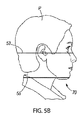
図1A乃至図1D、図4、図5A及び図5Bを参照して、患者Pは、最初に、装置20内部においてエミッタ40とレシーバ42との間に位置決めされる。図示例では、患者Pは、顎支持部48上に顎があって頭部支持部46上に頭部がある状態で、位置決めされる。次に、患者位置決めパネル68が手動で操作されて、装置制御部54に指示を出して装置20を制御し、患者PのX線撮像にとって全体的に適切な位置に装置20を位置決めする。これは、例えば、前述のように、ガイド部モータ60、顎支持部モータ61及び/または支持部モータ62によって、なされ得る。図4の図示例では、入力キー86を押すことで、図5A及び図5Bに示すように位置決めライト70が点灯し、前述の患者Pの位置決めをアシストできる。図5A及び図5Bは、X線処理のための所望の視野を輪郭付ける正中矢状ライト51と水平頂部ライト53と水平底部ライト55とを含む、例示的な位置決めライト70を図示している。付加的な患者位置決めライト70も採用され得る。位置決めライト70の使用は、選択的であり、図示されていない位置決めのための他の形態も使用され得る。患者位置決めパネル68の入力キー88を押すと、位置決め指示がユーザによって入力されつつあることを装置制御部54に信号伝達して、装置を更なる患者位置決めのための位置へと回転させる。
Referring to FIGS. 1A-1D, 4, 5A and 5B, a patient P is first positioned within the
患者位置決めパネル68上の矢印78、80を押すと、装置制御部54が指示されて、装置20が上下移動される。ユーザは、位置決めライト70を観察することができ、当該ライト70(従って装置)を患者P上の適切な位置へと位置決めするために矢印78、80、82、84を使用することができる。入力キー78、80を押すと、装置制御部54が指示されて、各支持部モータ62が制御されて装置20が移動される。矢印82、84を押すと、装置制御部54が指示されて、顎支持部モータ61が制御されて顎支持部48が上下移動される。前述のように、X線装置20を移動させる代わりに、例えば、装置20が患者Pに対して移動されるという前述の形態の代わりに、あるいはそれに加えて、患者Pが装置20に対して移動されるという異なる形態を利用することも可能である、ということが認識される。撮像後に入力キー90を押すことは、装置20を、患者が容易に装置20から出られる位置へと回転させる。
When the
図6を参照して、例えば3D撮像のような撮像処理のための所望の視野を全体的に獲得するべく患者Pが装置20に対して全体的に位置決めされると、コマンド制御部56は、ディスプレイ76を制御して、対象物の初期のビュー(view)92の提示を含み、本例では撮像されるべき患者Pの分析組織(anatomy)を提示する、グラフィカルユーザインタフェース(GUI)77を視覚的に提供する。初期のビュー92を含むGUI77は、装置制御部54によって制御される時、追加的あるいは代替的に、タッチスクリーンディスプレイ50上に表示され得るか、あるいは、他のグラフィカルディスプレイ装置上、例えば手持ち式装置上やテレビジョンスクリーン上等、に表示され得る。図6の図示例では、初期のビュー92は、患者の顎の包括モデル94を含む。付加的な例では、初期のビュー92は、例えば患者Pの特有の分析組織(anatomy)のような、対象物の画像やX線画像を含み得る。この付加的な例の例示的な実施形態では、初期のX線がX線撮像装置20で取り込まれることで、ユーザによって視認されるための初期のビュー92が生成され得る。
Referring to FIG. 6, when the patient P is globally positioned with respect to the
図6の図示例では、位置マーカー96がGUI77内に図示されている。図6に図示された位置マーカー96は、円形状と十字線とを有している。もっとも、他の形態の位置マーカーも利用され得る。位置マーカー96は、撮像が望まれている特定の3D容積を示す。一実施形態では、位置マーカー96は、撮像される容積の中心を示す。位置マーカー96は、初期のビュー92にオーバーラップして、初期のビュー92に対してGUI77内で移動可能である。追加の実施形態では、位置マーカー96は、撮像されるべき領域の容積を伝えるべくサイズ変更され得る。別の例では、初期のビュー92が位置マーカー96に対して移動され得る。別の例では、初期のビュー92と位置マーカー96の両方が、互いに対して移動可能であり得る。初期のビュー92と位置マーカー96との相対的な移動は、前述のように、入力装置74を介して及び/または例えばタッチスクリーンディスプレイ50のようなタッチスクリーン形態上の位置決めキー、例えば上下矢印91、93及び左右矢印95、97、を介して要請され得る。GUI77内の初期のビュー92の提示を修正する他の形態も利用され得る。例えば、ボイスコマンドや、マウスパッドや、ドラッグアンドドロップタッチスクリーンコマンド等、が利用され得る。
In the example shown in FIG. 6, the
パノラマ撮像様式、3D撮像様式及び頭蓋計測撮像様式間の選択をするための入力キーも、GUI77上に提供されている。本例は、3D撮像に関しており、それは入力キー99で選択され得る。もっとも、ここで説明される原理は、前述のように、他の撮像様式でも適用され得る。
Input keys for selecting between a panoramic imaging mode, a 3D imaging mode, and a cranial measurement imaging mode are also provided on the
図6及び図7を参照して、初期のビュー92を含むGUI77は、ユーザが3D撮像を所望する初期のビュー92上で興味対象の具体的領域を特定するべく、ユーザによって修正され得る。ユーザは、位置マーカー96を初期のビュー92上の興味対象の領域に移動することでGUI77を修正し、付加的な実施形態では、撮像されるべき所望の容積を包含するよう位置マーカー96のサイズを調整し得る。ユーザは、撮像ボタン66を押すことで入力装置64を操作し得る。それは、装置制御部54を指示して、撮像装置20を制御する。例えば、ガイド部29、支持部30及び回転部32が制御されて、患者Pに対するある位置に移動される。それは、初期のビュー92上での位置マーカー96と相応する。装置20は、エミッタ40とレシーバ42とが患者Pの1または2以上のスカウト画像を得るように動作するよう、位置決めされる。それは、GUI77上での位置マーカー96と初期のビュー92との相対的な位置決めに対応している。
Referring to FIGS. 6 and 7, the
一実施形態では、制御回路59が、患者の少なくとも一つのスカウト画像を得るべく初期のビュー92へのユーザ修正に従ってエミッタ及びレシーバを動作させるべくプログラムされている。それは、例示的に図8に図示されている。図8は、前述のユーザ入力に従って取られ得るスカウト画像を提示するグラフィカルディスプレイ101を図示している。複数の実施形態において、1または2以上のスカウト画像が、患者位置決めのために獲得され、利用され得る。スカウト画像102は、第1スカウト画像104と第2スカウト画像106を含んでいる。もっとも、当業者は、別の実施形態において、より多いまたはより少ないスカウト画像が獲得され得ることを認識するであろう。また、幾つかの実施形態では、スカウト画像は患者の歯科的顎顔面の領域の一部に限定され得るが、他の実施形態では、患者の頭部全体を含むがそれに限定はされない、患者のより大きな部位がスカウト画像において撮像され得る。スカウト画像102は、例示的には、患者の異なる角度から撮像される。図示の例では、直交ビュー104と正接ビュー106である。幾つかの例示の実施形態は、患者位置決め目的のために既に獲得されている少なくとも一つのスカウト画像を用いて、少なくとも一つの露出パラメータ値を更に自動的に決定する。更に別の実施形態では、前記少なくとも一つのスカウト画像が処理目的のためにのみ用いられ得てユーザには提示されない。
In one embodiment, the control circuit 59 is programmed to operate the emitter and receiver according to a user modification to the
図6を参照して、ここで更に詳細に説明される実施形態では、X線撮像システムが、自動的な1回量(1回分量)制御(ADC)を提供するように動作され得る。ここで更に詳細に説明されるADCのシステム及び方法は、前記少なくとも一つのスカウト画像から3DのX線撮像において用いられる少なくとも一つの露出パラメータ値を自動的に決定する機能及び利益を提供する。ここで説明される実施形態では、患者へのX線1回量が、より少ない技術的なユーザ入力に依存しながら、最適化され得る。一実施形態では、ユーザが、初期のビューがGUI77内で提示されている間に、「A」ボタン118を選択することで、自動1回量制御機能ないし動作モードを選択する。複数の実施形態において、撮像システムは、(「M」ボタン130の選択によって)マニュアルモードでも、(「T」ボタン132の選択によって)テストモードでも、動作し得る。マニュアルモードの一例では、露出設定が手動で選択される。テストモードの一例では、露出設定の具体的な予め設定された組合せが選択される。ADCモードの開始時、ユーザは、GUI120内に所望の画像の質を入力することが促される。GUI120は、選択された動作モードに個別的に指向された入力を受容するよう構成されたインタフェースを提示するよう変化し得る。例示的な実施形態では、ユーザは、獲得される画像の質を低、中及び高の間で選択するべく、低ボタン122、中ボタン124または高ボタン126を選択することによって、所望の画像の質を入力する。
With reference to FIG. 6, in an embodiment described in further detail herein, the x-ray imaging system may be operated to provide automatic dose (dose) control (ADC). The ADC systems and methods described in further detail herein provide the functionality and benefits of automatically determining at least one exposure parameter value used in 3D x-ray imaging from the at least one scout image. In the embodiments described herein, the x-ray dose to the patient can be optimized while relying on less technical user input. In one embodiment, the user selects the automatic bolus control function or mode of operation by selecting the "A"
ここで用いられる例示的な所望の画像の質は、獲得されるX線投影画像において見いだされるノイズの表示(representative)であり、あるいは、獲得されるX線投影画像の信号ノイズ比である。更なる実施形態では、ユーザは、3D画像再構築のための所望の質/ノイズレベルを入力する。ここで更に詳細に説明されるように、X線投影画像のノイズは、撮像される対象物/患者の物理的特性(例えば、サイズ、密度または減衰)とX線撮像装置を作動するのに用いられる露出パラメータ(例えば、mA、kV、露出時間、デューティサイクル、投影画像の数、ボクセルサイズ、及び、再構築システム及び/またはソフトウェア)との関数である。幾つかの実施形態では、ユーザが、例えば「フィルタリング」ボタン128を選択するかしないかによって、画像ノイズ低減ソフトウェアフィルトレーションが3D再構築処理において利用されるべきか否かを入力することを促され得る。更なる例示的な実施形態では、ユーザは、フィルタリングの量の入力表示を提供し得る。例えば、高フィルタリング、中フィルタリングまたは低フィルタリングが利用され得る。一般に、画像ノイズ低減ソフトウェアフィルトレーションは、低減された分解能のコストで、より大きいX線露出で撮像された画像と同一のノイズレベルまたは質を有する画像に帰結することが、認識されるであろう。従って、画像ノイズ低減ソフトウェアフィルトレーションの付加、あるいは、より高いフィルトレーションの使用は、患者に対する低減されたX線露出で好適な画像の質を達成することに帰結し得る。撮像の目的次第で、ユーザが必要な時だけ適切な質のレベル及び/または分解能/フィルタリングを選択して撮像される画像の目的を達成可能であることが、認識されるであろう。
An exemplary desired image quality as used herein is a representation of the noise found in the acquired x-ray projection image or the signal-to-noise ratio of the acquired x-ray projection image. In a further embodiment, the user enters a desired quality / noise level for 3D image reconstruction. As will be described in more detail herein, the noise in the x-ray projection image is used to operate the physical characteristics (eg, size, density or attenuation) of the object / patient being imaged and the x-ray imaging device. As a function of exposure parameters (eg, mA, kV, exposure time, duty cycle, number of projected images, voxel size, and reconstruction system and / or software). In some embodiments, the user is prompted to enter whether or not image noise reduction software filtration should be used in the 3D reconstruction process, for example, by selecting or not selecting a “Filtering”
例示的で非制限的な実施形態では、自動的な1回量制御(ADC)が、画像の質に依存して実施され得て、「mA補償」に基づき得る。このような実施形態では、mA補償は、ユーザがエミッタ電流(mA)を低減する時、システムが投影画像のフィルトレーションの強度を増大することであり得る。このような実施形態は、オペレータがより少ないエミッタ電流が特定のタスクにとって十分であると評価する時に、大人の患者に対する適用を見出し得る(例えば画像の質との妥協を進んで受け入れる)。そのような実施形態では、フィルトレーションが自動的に選択されて、画像ノイズレベルが一定を維持するか、あるいは、部分的に他のエミッタ電流値で補償されるか、あるいは、低下されたエミッタ電流の結果としてのノイズの上昇を低減させる。 In an exemplary, non-limiting embodiment, automatic dose control (ADC) can be implemented depending on image quality and can be based on "mA compensation". In such an embodiment, the mA compensation may be that the system increases the intensity of filtration of the projected image when the user reduces the emitter current (mA). Such an embodiment may find application for adult patients when the operator estimates that less emitter current is sufficient for a particular task (eg, willing to accept a compromise with image quality). In such embodiments, the filtration is automatically selected so that the image noise level remains constant, or is partially compensated for by other emitter current values, or a reduced emitter Reduces noise rise as a result of current.
図9乃至図11は、X線撮像装置における自動的な1回量制御の方法の例示的な実施形態を示すフローチャートである。 9 to 11 are flowcharts illustrating an exemplary embodiment of a method for automatic single dose control in an X-ray imaging apparatus.
図9は、X線撮像装置の自動的な露出制御の方法200の例示的な実施形態を図示している。方法200は、少なくとも一つのスカウト画像が獲得される工程202で始まる。前述のように、少なくとも一つのスカウト画像の獲得は、撮像のために一般化された領域ないし初期のビューが選択された後で、生じ得る。更なる実施形態では、当該少なくとも一つのスカウト画像は、既に獲得された画像であり得て、患者のCBCT画像、パノラマ画像または頭部計測画像を含むが、それらに限定はされない。代替的または付加的に、前述のようにX線撮像装置内に患者が適切に位置決めされた後で、スカウト画像が獲得され得て、ユーザは例示的に、3DX線撮像を選択し、X線撮像装置上で視野(FOV)サイズを選択し得る。もっとも、少なくとも一つのスカウト画像が工程202で獲得される前に種々の準備工程がなされ得ることが、当業者には認識されるだろう。複数の実施形態において、当該少なくとも一つのスカウト画像は、ここで説明されるように利用されることが可能な任意の画像であり得て、患者の位置決め目的で獲得される少なくとも一つの投影画像、自動の1回量制御の目的で獲得される少なくとも一つの画像、または、撮像手順の過程中に獲得される少なくとも一つの投影画像、を含むがそれらに限定されない。従って、ここで説明されるシステム及び方法は、種々の画像のいずれかを、当該画像が自動の1回量制御の目的に好適であるなら、当該画像が最初に得られた目的とは独立したスカウト画像として利用し得る。一実施形態において、前記少なくとも一つのスカウト画像は、露出パラメータの当該値が知られていて以下に更に詳細に説明されるように利用可能である限り、前述の露出パラメータにとってのデフォルト値で獲得される。複数の実施形態において、獲得されたスカウト画像は、患者の位置決めのために、及び/または、3D撮像のための精密なFOVを選択するために、利用され得る。
FIG. 9 illustrates an exemplary embodiment of a
次に、工程204において、撮像されるべき対象物または撮像されるべき対象物の一部の少なくとも一つの物理的特性が、前記少なくとも一つのスカウト画像の1または2以上の特性(例えば、限定ではないが、輝度、コントラスト、ノイズレベル、及び/または、可視の解剖学上の特徴)及び当該スカウト画像を撮像するために用いられる1または2以上の露出パラメータに基づいて、決定(測定)される。単なる例示的な比較の例が、ここで説明される方法の特徴を協調するべく、ここで用いられる。子供の患者の頭部の3D撮像と大人の患者の頭部の3D撮像とが比較される。例示的な付加的な実施形態では、画像のノイズレベルについて測定(決定)される。それは、前記対象物の少なくとも一つの物理的特性によってもたらされ得る。例示的な実施形態では、工程204で測定される物理的特性は、撮像されるべき対象物のサイズ、密度または減衰の少なくとも一つである。前記少なくとも一つのスカウト画像において、子供の患者の頭部が通常は、大人の患者の頭部の少なくとも一つのスカウト画像と比較して、それらスカウト画像が同一の露出パラメータ値で獲得される時、より小さく、より密度が小さく、より少ない減衰を示すことが認識されるであろう。前述のように、前記少なくとも一つのスカウト画像を得るために用いられる露出パラメータ値が知られている場合、当該スカウト画像内に撮像された対象物のサイズ、密度または減衰が、工程204で測定され得る。
Next, at
次に、少なくとも一つの露出パラメータ値が、工程206で決定される。前述のように、露出パラメータは、種々のパラメータを含み得る。それは、エミッタ電圧、エミッタ電流、投影画像の数、ボクセルサイズ、再構築システムまたはソフトウェア、露出時間、及び/または、デューティサイクル、を含むが、それらに限定はされない。これらの露出パラメータの1または2以上の値が、工程204からの決定された物理的特性から、少なくとも部分的に決定され得る。例示的な一実施形態では、エミッタ電圧、投影画像の数、及び、ボクセルサイズが、ADC操作との関連での使用のための値に、固定または予め規定され得る。これらの露出パラメータが予め決定された状態で、患者の1回量とX線撮像の質(ノイズレベルによって規定される)との両方が、工程206においてエミッタ電流(mA)の関数である。エミッタ電流の値は、従って、工程20で決定された物理的特性に基づいて少なくとも部分的に決定され得る。撮像されるべき対象物がより大きいかより密度が大きい場合、より多い減衰に帰結する。これは、X線撮像の目的を達成するために、より大きいエミッタ電流を要求する。従って、撮像されるべき対象物の増大されたサイズ、密度または減衰は、少なくとも一つの露出パラメータの増大された値に帰結する。
Next, at least one exposure parameter value is determined in step 206. As mentioned above, the exposure parameters may include various parameters. It includes, but is not limited to, emitter voltage, emitter current, number of projected images, voxel size, reconstruction system or software, exposure time, and / or duty cycle. One or more values of these exposure parameters may be determined, at least in part, from the determined physical properties from
工程208において、工程206で決定された少なくとも一つの露出パラメータが、複数の投影画像を獲得するために用いられる。複数の投影画像は、例示的に、X線エミッタ及びレシーバを患者の頭部回りにインクリメンタリーに回転しながら当該露出パラメータ値でX線撮像システムのエミッタまたは他の部位を操作しつつ一連のX線投影画像を当該回転インターバルで撮影することで、同一の露出パラメータ値で獲得される。
In
最終的に、工程210で、獲得された複数の投影画像から3D画像が再構築される。3D画像の再構築は、種々の再構築技術を用いて達成され得る。例示的な一実施形態では、初期再構築で始まり投影画像からの付加的情報に基づいて反復的に再構築を純化(refine)していく反復式の再構築技術、例えば代数的な再構築技術(ART)、が利用され得る。付加的な実施形態では、非反復式の再構築技術、例えばフィルタバック投影(FBP)、が利用され得る。前述の方法の実施形態200に加えて、更に詳細に説明されるように、方法の例示的な実施形態300、400が、説明された工程の各々を省いて実施され得る、あるいは、付加的な工程と共に実施され得る、ということが認識される。それらは、図面において特定のフローチャートとして図示されてはいないが、本発明の範囲内のものである。更なる実施形態は、ここで説明された操作及び機能を、異なる順序で実施し得るが、それもまた、本発明の範囲内のものである。
Finally, at
図10は、X線撮像装置内の自動的な1回量制御の方法の追加の例示的な実施形態300のフローチャートである。より具体的には、当該方法の例示的な実施形態300は、ユーザが、自動的な1回量制御の特徴を更に純化する(refine)ために用いられるユーザ入力を促されるか提供する、という実施形態を図示している。
FIG. 10 is a flowchart of an additional
方法200について前述されたのと同様、方法300は、工程302において、少なくとも一つのスカウト画像の獲得で始まる。当該少なくとも一つのスカウト画像が工程302で獲得された後で、幾つかの選択的な実施形態は、図6乃至図8に関して前述されたように視野(FOV)の選択を受容し得る。方法300は継続して、工程304において、前記少なくとも一つのスカウト画像、特には前記少なくとも一つのスカウト画像における選択された視野、を解析することによって、少なくとも一つの物理的特徴の値が決定される。方法200について前述されたように、前記少なくとも一つの物理的特徴は、対象物のサイズ、密度または減衰の値を含むように、前記スカウト画像から決定され得て、工程304における物理的特徴の値の当該決定は、前記少なくとも一つのスカウト画像が当該少なくとも一つのスカウト画像で経験される減衰の量を例示的に決定するために用いられ得るデフォルトの露出パラメータ値または知られた露出パラメータ値で獲得される複数の実施形態において、容易化され得る。付加的な実施形態では、別個のスカウト画像が、患者の位置決めのため及びADC計算のために用いられる。単なる例示的な実施形態では、付加的なスカウト画像、または、1または2以上の特定の角度からのスカウト画像が、更に詳細に説明されるように、減衰計算のために必要とされ得る。
As described above for
工程304で物理的特徴を決定するという実施形態では、スカウト画像の必要とされる数は、撮像される物理的構造の具体的な適用例に依存し得る。一実施形態では、スカウト画像が撮像されるべき対象物を完全にカバーして対象物の減衰の信頼性ある評価がなされ得るように、十分な数のスカウト画像が解析される。例示的な一実施形態では、決定される物理的特徴が、平均ノイズレベル(例えばピクセル標準偏差値)や平均密度(例えばピクセル平均値)であり得る。複数の実施形態では、工程304における物理的特徴の決定は、少なくとも一つのスカウト画像が公知または参照の露出パラメータ値で獲得される場合、容易化される。例示的な一実施形態では、前記少なくとも一つのスカウト画像は、公知の参照対象物サイズの再構築容積での公知のノイズレベルに帰結するために選択される参照エミッタ電流で獲得される。当該参照エミッタ電流及び帰結するノイズレベルに対する比較において、更に詳細に説明されるように、より低いエミッタ電流が決定されると、より多いノイズを含む再構築画像に帰結し得るし、より高いエミッタ電流は、より少ないノイズを含む再構築画像に帰結し得る。同様に、更に詳細に説明されるように、複数の実施形態における露出パラメータの決定は、再構築される画像の質(例えばノイズレベル)とスカウト画像から工程304で決定される前記少なくとも一つの物理的特徴との間の確立した関係に依存する。それは、スカウト画像のノイズレベルを含み得る。前記少なくとも一つのスカウト画像を獲得するために用いられるエミッタ電流が異なる患者間でのスカウト画像に亘って一定である場合、撮像されるべき対象物のサイズ、密度及び減衰は、後に獲得される投影画像と再構築される3D画像との質において、重要な要因である。複数のスカウト画像が用いられる実施形態では、当該複数のスカウト画像に亘って露出パラメータ値(エミッタ電流、エミッタ電圧、視野サイズ及び画像分解能を含む)が一定を保持すればするほど、物理的特徴の決定がより直線的(直接的)になって、物理的特徴の決定をなすための較正及び/または補償がより少なくて済む。
In embodiments where physical features are determined in
工程306において、所望の画像の質についてのユーザ入力が受容される。前述のように、所定の実施形態の一つの潜在的な利点は、適切な撮像用の露出パラメータ値を選択するための技術的な知識ないし経験についてのユーザ依存性が低減することである。従って、一実施形態では、図6のユーザインタフェースに図示されたように、ユーザは、3D再構築の質を、所望に、低、中、高の選択として入力する。それは、3D再構築が用いられる目的、及び/または、画像の質のニーズに依存する。幾つかの実施形態では、画像の質は、完全にまたは部分的に、複数の投影画像ないし結果としての3D再構築における受容可能なノイズのレベルを表し得る。例えば、工程306における所望の質のユーザ入力は、ユーザにとって受容可能なノイズレベルまたは具体的な信号ノイズ比の、高、中、低の選択を含み得る。
At
工程308において、少なくとも一つの露出パラメータ値が決定される。前記少なくとも一つの露出パラメータ値は、様々な態様で、工程308において決定され得る。ある実施形態では、露出パラメータ値は、工程304で決定された全体の減衰という物理的特徴と視野サイズとに基づいて決定され得て、予め決定された受容可能なノイズレベルで投影画像または再構築3D画像を生成し得る。別の実施形態では、所望の質のユーザ入力/選択が、受容可能なノイズレベルを規定するために利用される。この実施形態は、ユーザに、自動的に決定された少なくとも一つの露出パラメータ値を超える付加的な制御を提供する。例示的な実施形態では、前記少なくとも一つの露出パラメータ値は、エミッタ電流である。例示的な選択的な実施形態では、工程310において、所望の分解能のユーザ入力が受容される。再構築された画像におけるノイズレベルは、ノイズ低減ソフトウェアフィルトレーションの使用によっても影響され得る。ノイズ低減ソフトウェアフィルトレーションは、ピクセル値に亘って平均化することによって、再構築される画像を「柔軟にする」乃至ぼやけさせて、分解能を低減する。ピクセル間での差異の程度を低減して、画像内の全体のノイズを低減することによって、ノイズ低減ソフトウェアフィルトレーションは、低減されたエミッタ電流と患者1回量で、典型的には分解能は低減されるが、同一のノイズレベルの達成を可能にする。従って、工程310において所望の分解能を入力することによって、低減された分解能が受容可能であることをユーザが指示する場合、エミッタ電流と全体の患者1回量が、物理的特徴及び所望の画像質のみから決定されていたものより、更に低減され得る。
At
例示的な実施形態では、所望の分解能のユーザ入力は、高分解能、中分解能または低分解能のユーザ選択であり得る。これら実施形態の文脈での分解能は、ノイズ低減ソフトウェアフィルトレーションによって影響され得るので、付加的な実施形態では、所望の分解能のユーザ入力は、図6のユーザ入力制御に例示的に示されているように、ノイズ低減ソフトウェアフィルトレーションを使用すべきか否かの指示であり得る。更なる実施形態では、ソフトウェアフィルタリングの低レベル、中レベルまたは高レベルのユーザ入力も、受容され得る。 In an exemplary embodiment, the desired resolution user input may be a high, medium or low resolution user selection. In additional embodiments, the user input at the desired resolution is exemplarily shown in the user input controls of FIG. 6, since the resolution in the context of these embodiments may be affected by noise reduction software filtration. As such, it may be an indication of whether to use noise reduction software filtration. In further embodiments, low, medium or high levels of user input of software filtering may also be accepted.
所望の分解能のユーザ入力が工程310で受容された後で、好適なノイズフィルタリングが決定される。例示的には、前述のように、低、中及び高程度のノイズ低減ソフトウェアフィルタリングが利用可能であり、これらの選択肢の1または2以上がユーザによって選択され得る。付加的な実施形態では、工程304で決定されるような測定される全体の減衰が、好適なノイズフィルタリングを自動的に決定するために利用され得る。ほとんどの場合において、再構築画像は、より強い投影画像ノイズ低減ソフトウェアフィルタリングによって、より低レベルのノイズ低減ソフトウェアフィルタリングによる場合よりも、よい大きな程度でぼかされる。より強いノイズフィルタリングは、ノイズレベルを低減する際にもっとも多くの影響を有する。従って、大抵の場合、より低い全体の減衰(例えば、子供の頭部)は、より低いノイズ低減ソフトウェアフィルタリングの選択に帰結し、より全体の減衰が大きい画像(例えば、大人の頭部の画像)は、同様の画像露出値を達成するために、より高レベルのノイズ低減ソフトウェアフィルタリングによって処理され得る。
After the desired resolution of user input has been received at
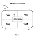
図12は、画像の質のユーザ入力選択を受容するように構成されたグラフィカルユーザインタフェース150の一部の例示的な実施形態を図示している。例示的な一実施形態において、GUI150は、図6を参照しつつ前述された所望の画像の質のGUI120に対する付加的な実施形態である。GUI150には、例示的な5つの選択肢が、実際の撮像のパラメータ値の「技術」に関するのではなく「効果」に関して、ユーザに提示されている。これらの選択肢は、「最小ノイズ、高精細」152、「低減1回量、高精細」154、「標準画像質」156、「最小ノイズ、低減精細」158、及び、「低減1回量、低減精細」160を含んでいる。一実施形態では、提示される5つの選択肢が、1回量についての降順、及び、画像フィルトレーションについての昇順、を表している。選択肢152及び154は、より低いノイズフィルトレーションを提供し、「高精細」表示をもたらす。一方、選択肢158及び160は、「低減精細」によって指示される増大されたノイズフィルトレーションを提供する。比較的、選択肢152及び158(「最小ノイズ」)は、選択肢154及び160(「低減1回量」)よりも、それぞれ、より高いエミッタ電流を使用する。「標準画像質」156の選択肢は、1回量と精細度との間のバランスを表している。
FIG. 12 illustrates an exemplary embodiment of a portion of a
図10に戻って、ノイズ低減ソフトウェアフィルタリングが用いられる実施形態では、前述のように、システムは低減されたエミッタ電流を採用し得て、より低い患者1回量に帰結する。従って、ノイズ低減ソフトウェアフィルタリングの使用及び強度が、工程308において、少なくとも一つの露出パラメータ値を決定するために、実施形態において更に使用され得る。幾つかの実施形態では、露出パラメータ値は、工程308において決定されてその後に撮像装置によって使用される実際の数値として、グラフィカルディスプレイ上において例示的に、更にGUI77内で例示的に、工程312において提示され得る。別の実施形態では、露出パラメータ値は、相対的な条件でユーザに表示され得る。非制限的な例では、露出パラメータがエミッタ電流である場合、ユーザは、投影画像の獲得に用いるために決定されたエミッタ電流が低、中及び高のいずれであるかを示す情報を、提示され得る。
Returning to FIG. 10, in embodiments in which noise reduction software filtering is used, as described above, the system may employ a reduced emitter current, resulting in a lower patient dose. Thus, the use and strength of noise reduction software filtering may be further used in embodiments to determine at least one exposure parameter value at
幾つかの実施形態では、工程314に続いて、決定された少なくとも一つの露出パラメータ値と、もしあれば決定されたノイズ低減ソフトウェアフィルタリングとが、確認のためにユーザに提示される。幾つかの実施形態では、決定された露出パラメータ値及び/またはノイズ低減ソフトウェアフィルタリングの使用を、ユーザに提示することが望まれ得る。これは、ユーザに、1回量制御を達成するためのこれら機能の使用について確認の機会を与えるだけでなく、現在の物理的特性の患者のために所望の画像の質及び/または所望の分解能のユーザ入力を達成するノイズ低減ソフトウェアフィルタリングの選択と露出パラメータ値について時間と共にユーザがより経験を積むようにユーザを教育する上でも役立ち得る。
In some embodiments, following
工程316において、撮像装置は、決定された少なくとも一つの露出パラメータを用いて、複数の投影画像を獲得するように作動される。例示的な一実施形態では、少なくとも一つの露出パラメータは、エミッタ電流であり、撮像装置は、決定されたエミッタ電流の値でエミッタを作動させて、複数の投影画像を得る。
In
ノイズ低減ソフトウェアフィルタリングが使用のために決定される実施形態では、工程318において、決定されたノイズフィルタが投影画像をフィルタリングするために用いられる。前述のように、投影画像のフィルタリングは、獲得される画像に亘ってピクセル値を平均化ないし円滑化して、典型的には分解能を低減してノイズレベルを改善する。最終的に、工程320において、複数の投影画像から3D画像が再構築される。前述のように、図9を参照して、様々な3D画像再構築技術が利用可能であり、方法の例示的な実施形態300において利用され得る。
In embodiments where noise reduction software filtering is determined for use, at
付加的な例示的な実施形態では、前述のように少なくとも一つのスカウト画像が工程302において獲得された後で、対象容積のグレー値について荒い(ラフな)評価がなされ得る。グレー値は、投影画像の実際の獲得前にスカウト画像を逆投影(back−projection)することによって評価され得る。別の実施形態では、スカウト画像が逆投影される前に、スカウト画像が最初に低解像度処理され得る(及び/または平均化され得る)、更なる追加の実施形態では、スカウト画像及び/または逆投影画像が、処理され得る(例えば、低解像度処理され得る、及び/または、平均化され得る)。次に、最小値評価、最大値評価、差分評価、平均評価または中央値評価のようなグレー値の二次的な評価が、逆投影スカウト画像から計算され得る。グレー値の二次的な評価は、投影画像の実際の獲得のために用いられる少なくとも一つの撮像パラメータ(例えば、エミッタ電流(mA)、画像の数、または、KVS)及び/または画像処理パラメータ(例えば、プレ処理フィルタ、MAR)を決定するために、工程308において利用される。一実施形態では、工程322からのグレー値のこれらの評価は、決定された物理的特徴として利用され得るし、あるいは、工程308の少なくとも一つの撮像パラメータの決定の際に用いられる独立値として利用され得る。
In additional exemplary embodiments, after at least one scout image has been acquired at
図11は、X線撮像装置の自動的な1回量制御の方法の一実施形態400のフローチャートである。
FIG. 11 is a flowchart of an
方法400の複数の部分は、方法200、300について前述された部分と同様である。全体として、方法400は、複数の投影画像を捕捉するために、スカウト画像が撮像手順の過程において獲得される実施形態を開示している。この文脈において、スカウト画像は、3D再構築の際に用いられ得る撮像手順中に獲得された投影画像であり得る。幾つかの非制限的な実施形態では、自動的な1回量制御の方法が、撮像手順中に実施され得る。自動的な1回量制御の方法は、撮像手順の開始時に実施される任意の自動的な1回量制御から離れて、ないし、それに加えて、撮像手順内の他のタイミングでも実施され得る。方法400では、所望の画像の質のユーザ入力が、工程402で受容される。所望の画像の質のユーザ入力は、例示的には、図6を参照して前述され、及び、図10を参照して更に詳細に説明された、GUIを介して受容され得る。また、工程404において、方法400の幾つかの実施形態は、更に、図10を参照して前述されたように、所望の分解能のユーザ入力を受容し得る。所望の画像の質及び/または所望の分解能のユーザ入力が受容された後で、3D撮像手順が工程406において開始される。3D撮像手順は、複数の投影画像の獲得を含んでいる。ここで方法400について説明されるように、例示的な実施形態では、複数の投影画像が2つの部分で獲得される。工程408において、撮像装置は、複数の投影画像の第1部分として、少なくとも一つのスカウト画像を獲得する。当該少なくとも一つのスカウト画像は、撮像されるべき対象物(例えば患者の頭部)の物理的特徴を表すのに好適であるように、撮像されるべき対象物に対してある角度で獲得される。複数の実施形態において、2または3以上のスカウト画像が獲得される。更なる実施形態では、獲得されたスカウト画像の少なくとも2つが、互いに略直交している。
Portions of
複数の投影画像の第1部分として獲得された少なくとも一つのスカウト画像は、撮像されるべき対象物の少なくとも一つの物理的特徴を決定するために、工程410において分析される。前述のように、前記少なくとも一つの物理的特徴は、撮像されるべき対象物のサイズ、密度及び/または減衰であり得る。工程410における前記少なくとも一つの物理的特徴の決定は、前記少なくとも一つのスカウト画像が知られた露出パラメータ値で工程408において獲得されることによって容易化され、更にまた、例えば知られた物理的特徴を有する対象物から予測される画像結果と実際のスカウト画像とを比較することによって前記知られた露出パラメータ値を較正することによって容易化され得る。これらの較正及び関係は、例示的には、コンピュータプロセッサないしコンピュータプロセッサに通信可能に接続されたメモリにおいて、決定され得るかモデル化され得て、記憶され得る。
At least one scout image acquired as a first portion of the plurality of projection images is analyzed at
少なくとも一つの物理的特徴が、工程410において決定されると、少なくとも一つの露出パラメータ値が、工程412において決定され得る。少なくとも一つの物理的特徴からの少なくとも一つの露出パラメータ値の決定は、前述された通りである。複数の実施形態において、少なくとも一つの露出パラメータ値は、少なくとも一つの物理的特徴のみから決定され得るし、あるいは、追加の情報と組み合わせて決定され得る。当該追加の情報とは、複数の実施形態において、工程402で受容される所望の画像の質のユーザ入力を含み得る。更なる実施形態において、所望の分解能のユーザ入力が工程404で受容される場合、工程414で、当該所望の分解能のユーザ入力を達成するノイズフィルタリングのレベルが決定される。前述のように、ノイズフィルタリングが使用される場合、これは、更に、患者1回量の低減を可能にし得るし、従って、工程412において、ノイズフィルタリングが使用されない場合よりも少ない露出パラメータ値の決定をもたらし得る。
Once at least one physical characteristic has been determined at
少なくとも一つの露出パラメータ値が工程412で決定された後、制御回路は、撮像装置を作動させて、少なくとも一つの露出パラメータ値を工程412で決定された値に調整する。少なくとも一つの露出パラメータ値を工程416で調整した後、撮像装置は工程418で作動して、複数の投影画像の第2部分を獲得する。複数の投影画像の第2部分は、3D再構築の際に用いられるべき複数の投影画像の獲得を完了させる。一実施形態において、複数の投影画像の第1部分は、選択的に、比較的少数であり得るが、調整された少なくとも一つの露出パラメータ値で獲得された複数の投影画像の第2部分は、例示的な実施形態では、100以上の投影画像であり得る。
After the at least one exposure parameter value is determined in
ノイズフィルタリングが(例えばユーザによって)選択された実施形態では、複数の投影画像は、工程420でフィルタリングされて、投影画像のノイズレベルが改善されて結果としての3D再構築におけるノイズレベルが改善される。更に、複数の投影画像がフィルタリングされてもされなくても、3D画像は複数の投影画像から、例えば公知の再構築技術によって、工程422で生成される。
In embodiments in which noise filtering has been selected (eg, by a user), the plurality of projection images are filtered at
当業者によって理解される通り、本発明は、対象物を通してX線を放射するエミッタと当該X線を受容するレシーバとを有する撮像装置と、前記エミッタを制御して前記レシーバによって受容されるX線を処理して対象物のX線画像を生成する制御回路と、を含むX線撮像システムの例を提供する。撮像装置及び制御回路の具体例が、添付の図面を参照して説明されている。これらの例は、限定的なものではなく、本発明の概念は、異なる形態の制御回路を有する他のタイプの撮像装置にも適用可能である。ここで説明された例では、制御回路が、少なくとも一つの露出パラメータ値を決定する。幾つかの実施形態では、これは、所望の質のユーザ選択と、少なくとも一つのスカウト画像の分析に基づく物理的特徴と、を通して達成される。付加的な例示的な実施形態では、これは、撮像手順の間に実施され得る。 As will be appreciated by those skilled in the art, the present invention is directed to an imaging device having an emitter that emits X-rays through an object and a receiver that receives the X-rays, and an X-ray that controls the emitter and is received by the receiver. And a control circuit that generates an X-ray image of the object by processing the image data. Specific examples of the imaging device and the control circuit are described with reference to the accompanying drawings. These examples are not limiting and the concepts of the present invention are applicable to other types of imaging devices having different forms of control circuits. In the example described here, the control circuit determines at least one exposure parameter value. In some embodiments, this is achieved through a desired quality of user selection and physical characteristics based on an analysis of at least one scout image. In additional exemplary embodiments, this may be performed during an imaging procedure.
X線露出パラメータ値の選択は、時々、患者への過剰のX線露出を回避しながら所望の画像の質を達成するために、相当のオペレータの経験を要求し得る、ということを本件発明者は認識していた。特定のタイプのX線撮像を稀にしか実施しないオペレータは、このようなオペレータの経験を有しない可能性がある。不必要に高いエミッタ電流の選択は、患者の1回量を増大させ、過剰に低いエミッタ電流の選択は、不十分な画像の質(例えば過剰な画像ノイズ)に帰結し得る。更に、画像の質が不十分である場合、オペレータは、追加の撮像セッションを実施することが必要であるかもしれない。これは、追加の患者の1回量に帰結する。ここで説明されたシステム及び方法の所定の実施形態は、少なくとも一つのスカウト画像から決定される少なくとも一つの物理的特徴に基づいて少なくとも一つの最適な露出パラメータ値を自動的に計算する自動の1回量制御(ADC)を実施し得る。複数の実施形態において、システム及び方法は、更に、少なくとも一つの露出パラメータ値との関連で最適なノイズフィルタリングのレベルを決定し得る。これは、患者の1回量の更なる低減に帰結し得る。 The present inventors have found that the choice of x-ray exposure parameter values can sometimes require considerable operator experience to achieve the desired image quality while avoiding excessive x-ray exposure to the patient. Was aware. Operators that rarely perform certain types of X-ray imaging may not have such operator experience. Choosing an unnecessarily high emitter current increases the patient's dose, and choosing an excessively low emitter current can result in poor image quality (eg, excessive image noise). Further, if the quality of the image is poor, the operator may need to perform an additional imaging session. This results in an additional patient dose. Certain embodiments of the systems and methods described herein provide an automatic one that automatically calculates at least one optimal exposure parameter value based on at least one physical feature determined from at least one scout image. Dosage control (ADC) may be implemented. In embodiments, the systems and methods may further determine an optimal level of noise filtering in relation to the at least one exposure parameter value. This may result in a further reduction of the patient's dose.
各図に提示された、機能的なブロック図、作動シーケンス、及び、フロー図は、本発明の新規な特徴を実施するための例示的な構造、環境及び方法論を表している。説明の簡単化の目的で、ここに含まれる方法論は、機能図、作動シーケンス、または、フロー図の形態であり得て、一連の工程として説明され得るが、当該方法論は、当該工程の順序によって限定されない、ということが理解される。幾つかの工程は、図示され説明されたものとは異なる順序で実施され得る、及び/または、他の工程と同時に実施され得る。たとえば、当業者は、ある方法が、一連の関連する状態またはイベントとして、例えば状態図として、表され得ることを理解するであろう。更に、幾つかの実装では、図示された動作ないし工程の全てが必要とされる訳ではない。 The functional block diagrams, operational sequences, and flow diagrams presented in the figures represent exemplary structures, environments, and methodologies for implementing the novel features of the present invention. For purposes of simplicity, the methodology contained herein may be in the form of a functional diagram, sequence of operations, or flow diagram, and may be described as a series of steps, wherein the methodology depends on the order of the steps. It is understood that this is not a limitation. Some steps may be performed in a different order than shown and described, and / or may be performed simultaneously with other steps. For example, those skilled in the art will understand that a methodology could be represented as a series of related states or events, such as in a state diagram. Further, some implementations may not require all of the acts or steps shown.
ここに記載された説明は、本発明を開示するための例を用いており、ベストモードを含んでおり、当業者が本発明を利用することを可能にする。本発明の範囲は、特許請求の範囲によって規定され、当業者に実施可能な他の例を含み得る。そのような他の例は、特許請求の範囲の文言と異ならない要素を有する場合、あるいは、等価な要素を含む場合、特許請求の範囲の範囲内であることが意図されている。 The description set forth herein uses examples to disclose the invention, including the best mode, and allows one of ordinary skill in the art to make use of the invention. The scope of the invention is defined by the claims, and may include other examples that occur to those skilled in the art. Such other examples, having elements that do not differ from the language of the claims, or including equivalent elements, are intended to be within the scope of the claims.
Claims (19)
X線を生成して当該X線を対象物に向けて方向付けるように構成されたX線エミッタと、
前記X線エミッタからのX線を受容するように構成されたX線レシーバと、
前記X線エミッタ及び前記X線レシーバに通信可能に接続された少なくとも一つのコンピュータプロセッサと、
を備え、
前記X線エミッタ及び前記X線レシーバは、前記対象物の少なくとも一つの画像を獲得するように構成されており、
前記少なくとも一つのコンピュータプロセッサは、前記少なくとも一つの画像からノイズレベルを決定し、少なくとも当該ノイズレベルと3次元X線画像のノイズレベルとに基づいてエミッタ電流値を決定するように構成されており、
前記X線エミッタ及び前記X線レシーバは、更に、前記エミッタ電流値を用いて前記対象物の複数の投影画像を獲得するように構成されており、
前記少なくとも一つのコンピュータプロセッサは、更に、前記複数の投影画像から前記3次元X線画像を再構成するように構成されている
ことを特徴とするX線撮像システム。 An X-ray imaging system,
An X-ray emitter configured to generate X-rays and direct the X-rays toward an object;
An X-ray receiver configured to receive X-rays from the X-ray emitter;
At least one computer processor communicatively connected to the X-ray emitter and the X-ray receiver;
With
The X-ray emitter and the X-ray receiver are configured to acquire at least one image of the object;
The at least one computer processor, the noise level determined from at least one image, is configured to determine the emitter current value based on the noise level of at least the noise level and the three-dimensional X-ray images,
The X-ray emitter and the X-ray receiver are further configured to acquire a plurality of projection images of the object using the emitter current value ;
The at least one computer processor further, X-ray imaging system, characterized in that it is configured to reconstruct the three-dimensional X-ray image from the plurality of projection images.
を更に備え、
前記少なくとも一つのコンピュータプロセッサは、更に、少なくとも前記3次元X線画像のノイズレベルの当該ユーザ入力に基づいて前記エミッタ電流値を決定するように構成されている
ことを特徴とする請求項1に記載のX線撮像システム。 An input device communicatively coupled to the at least one computer processor and configured to receive a user input of a noise level of the three-dimensional x-ray image ;
The at least one computer processor is further claimed in claim 1, characterized in that it is configured to determine the emitter current value based on the noise level the user input of at least the three-dimensional X-ray images X-ray imaging system.
前記コンピュータプロセッサは、更に、前記受容された画像分解能のユーザ入力に基づいてノイズフィルタを選択し、前記獲得された複数の投影画像から前記3次元X線画像を再構築する前に、前記ノイズフィルタを用いて、前記複数の投影画像をフィルタリングするように構成されている
ことを特徴とする請求項2に記載のX線撮像システム。 The input device is further configured to receive image resolution user input,
The computer processor further selects a noise filter based on the user input of the received image resolution and the noise filter prior to reconstructing the three-dimensional x-ray image from the acquired plurality of projection images. The X-ray imaging system according to claim 2 , wherein the plurality of projection images are filtered using a plurality of images.
前記少なくとも一つの画像は、予め設定された視野(FOV)サイズ、及び0、予め設定された分解能、で獲得される
ことを特徴とする請求項1に記載のX線撮像システム。 The at least one computer processor further determines attenuation of the object, and further includes determining a noise level from at least one image of the object, a noise level of the three-dimensional X-ray image, and the attenuation of the object. Is configured to determine the emitter current value from
The X-ray imaging system according to claim 1 , wherein the at least one image is acquired at a preset field of view (FOV) size and at 0, a preset resolution.
X線エミッタとX線レシーバとによって、対象物の少なくとも一つの画像を獲得する工程と、
少なくとも一つのコンピュータプロセッサを用いて、前記少なくとも一つの画像から当該少なくとも一つの画像のノイズレベルである画像データを決定する工程と、
前記少なくとも一つのコンピュータプロセッサを用いて、前記ノイズレベルと3次元X線画像のノイズレベルとに基づいて、少なくとも一つの撮像パラメータ値を決定する工程と、
前記X線エミッタ及び前記X線レシーバによって、前記少なくとも一つの撮像パラメータ値を用いて、前記対象物の複数の投影画像を獲得する工程と、
前記少なくとも一つのコンピュータプロセッサを用いて、前記複数の投影画像から前記3次元X線画像を再構成する工程と、
を備えたことを特徴とする方法。 A method of single dose control in three-dimensional X-ray imaging,
Acquiring at least one image of the object by the X-ray emitter and the X-ray receiver;
Using at least one computer processor, determining image data that is a noise level of the at least one image from the at least one image ,
Using the at least one computer processor to determine at least one imaging parameter value based on the noise level and a noise level of the three-dimensional X-ray image;
Acquiring, by the X-ray emitter and the X-ray receiver, a plurality of projection images of the object using the at least one imaging parameter value;
Using said at least one computer processor, a step of reconstructing the three-dimensional X-ray image from the plurality of projection images,
Method characterized by comprising a.
ことを特徴とする請求項5に記載の方法。 The method of claim 5 , wherein the at least one imaging parameter value comprises an emitter current.
を更に備え、
前記エミッタ電流は、更に、前記対象物のサイズ及び前記対象物の減衰のうちの前記少なくとも一方に基づいて決定される
ことを特徴とする請求項6に記載の方法。 Determining at least one of the size of the object and the attenuation of the object,
The method of claim 6 , wherein the emitter current is further determined based on the at least one of the size of the object and the attenuation of the object.
ことを特徴とする請求項5乃至7のいずれかに記載の方法。 The at least one image includes a plurality of images acquired with at least one of a preset imaging parameter, a preset field of view (FOV) size, and a preset resolution. The method according to any one of claims 5 to 7 .
を更に備え、
前記少なくとも一つの撮像パラメータ値は、更に、前記3次元X線画像の画像の質の前記ユーザ入力に基づいて前記少なくとも一つのコンピュータプロセッサによって決定される
ことを特徴とする請求項5乃至8のいずれかに記載の方法。 Receiving image quality user input of the three-dimensional X-ray image .
Said at least one imaging parameter values, further, more of claims 5 to 8, characterized in that it is determined by the at least one computer processor based on the user input quality of the image of the three-dimensional X-ray images The method described in Crab.
前記受容された画像分解能のユーザ入力に基づいて、前記少なくとも一つのコンピュータプロセッサを用いて、ノイズフィルタを選択する工程と、
前記獲得された複数の投影画像から前記3次元X線画像を再構築する前に、前記ノイズフィルタを用いて、前記複数の投影画像をフィルタリングする工程と、
を更に備えたことを特徴とする請求項9に記載の方法。 Receiving a user input of image resolution;
Selecting a noise filter using the at least one computer processor based on the received image resolution user input;
Filtering the plurality of projection images using the noise filter before reconstructing the three-dimensional X-ray image from the acquired plurality of projection images;
The method of claim 9 , further comprising:
ことを特徴とする請求項10に記載の方法。 The method of claim 10 , wherein the at least one imaging parameter value is further determined by the at least one computer processor based on a noise filter selected by the computer processor.
前記少なくとも一つのコンピュータプロセッサを用いて、前記少なくとも一つの画像における対象物の前記減衰に基づいて少なくとも一つの撮像パラメータ値を決定する工程と、
を更に備えたことを特徴とする請求項5乃至11のいずれかに記載の方法。 Using the at least one computer processor to determine attenuation of an object in the at least one image ;
Using the at least one computer processor to determine at least one imaging parameter value based on the attenuation of the object in the at least one image;
The method according to any one of claims 5 to 11 , further comprising :
当該方法は、
複数の処理画像を捕捉するべく3次元撮像手順を開始する工程と、
前記撮像パラメータ値を、前記プロセッサによって決定されたエミッタ電流値に調整する工程と、
を更に備え、
前記少なくとも一つの画像は、複数の処理画像の第1部分を有し、
前記複数の投影画像は、前記複数の処理画像の第2部分であり、
前記複数の投影画像は、前記コンピュータプロセッサによって決定されたエミッタ電流値で獲得され、
前記コンピュータプロセッサは、前記複数の処理画像から前記3次元X線画像を再構築することを特徴とする請求項5乃至12のいずれかに記載の方法。 The at least one image is acquired at a first emitter current;
The method is
Initiating a three-dimensional imaging procedure to capture a plurality of processed images;
Adjusting the imaging parameter value to an emitter current value determined by the processor;
Further comprising
The at least one image has a first portion of a plurality of processed images;
The plurality of projection images is a second part of the plurality of processing images,
The plurality of projection images are acquired at an emitter current value determined by the computer processor;
It said computer processor, the method according to any one of claims 5 to 12, characterized in that reconstructing the three-dimensional X-ray image from the plurality of processed images.
前記少なくとも一つの撮像パラメータは、更に、前記少なくとも一つのグレー値に基づいて決定される
ことを特徴とする請求項5乃至13のいずれかに記載の方法。 Evaluating the at least one gray value of the volume of interest from the at least one image,
The method according to any of claims 5 to 13 , wherein the at least one imaging parameter is further determined based on the at least one gray value.
最初のエミッタ電流値で作動するX線エミッタとX線レシーバとによって、対象物の少なくとも一つの画像を獲得する工程と、
少なくとも一つのコンピュータプロセッサを用いて、前記少なくとも一つの画像におけるノイズレベルを決定する工程と、
前記少なくとも一つのコンピュータプロセッサを用いて、前記ノイズレベルと3次元X線画像の画像の質とに基づいて、新しいエミッタ電流値を決定する工程と、
前記新しいエミッタ電流値で作動する前記X線エミッタ及び前記X線レシーバによって、前記対象物の複数の投影画像を獲得する工程と、
前記少なくとも一つのコンピュータプロセッサを用いて、前記複数の投影画像から前記3次元X線画像を再構成する工程と、
を備えたことを特徴とする方法。 An exposure control method in three-dimensional X-ray imaging,
Acquiring at least one image of the object by an X-ray emitter and an X-ray receiver operating at an initial emitter current value;
Using at least one computer processor to determine a noise level in the at least one image;
Using the at least one computer processor to determine a new emitter current value based on the noise level and image quality of the three-dimensional x-ray image;
Acquiring a plurality of projected images of the object by the X-ray emitter and the X-ray receiver operating at the new emitter current value;
Using said at least one computer processor, a step of reconstructing the three-dimensional X-ray image from the plurality of projection images,
A method comprising:
ことを特徴とする請求項15に記載の方法。 The method of claim 15 , wherein the noise level is a noise level caused by the X-ray receiver.
前記受容された画像分解能のユーザ入力に基づいて、前記少なくとも一つのコンピュータプロセッサを用いて、ノイズフィルタを選択する工程と、
前記獲得された複数の投影画像から前記3次元X線画像を再構築する前に、前記ノイズフィルタを用いて、前記複数の投影画像をフィルタリングする工程と、
を更に備え、
前記新しい撮像パラメータ値は、更に、少なくとも前記コンピュータプロセッサによって選択されたノイズフィルタに基づいて、前記少なくとも一つのコンピュータプロセッサによって決定される
ことを特徴とする請求項15または16に記載の方法。 Receiving a user input of image resolution;
Selecting a noise filter using the at least one computer processor based on the received image resolution user input;
Filtering the plurality of projection images using the noise filter before reconstructing the three-dimensional X-ray image from the acquired plurality of projection images;
Further comprising
17. The method of claim 15 or 16 , wherein the new imaging parameter value is further determined by the at least one computer processor based at least on a noise filter selected by the computer processor.
を更に備えたことを特徴とする請求項15乃至17のいずれかに記載の方法。 The method according to any one of claims 15 to 17 to enter the image quality of a three-dimensional X-ray image, characterized in that further comprising the step of receiving.
ことを特徴とする請求項18に記載の方法。 The method of claim 18 , wherein the at least one image is acquired with a preset field of view (FOV) size and a preset resolution.
Applications Claiming Priority (3)
| Application Number | Priority Date | Filing Date | Title |
|---|---|---|---|
| US14/304,378 US10278666B2 (en) | 2014-06-13 | 2014-06-13 | Systems and methods of automated dose control in x-ray imaging |
| US14/304,378 | 2014-06-13 | ||
| PCT/IB2015/001261 WO2015189694A1 (en) | 2014-06-13 | 2015-05-27 | Systems and methods of automated dose control in x-ray imaging |
Publications (3)
| Publication Number | Publication Date |
|---|---|
| JP2017521203A JP2017521203A (en) | 2017-08-03 |
| JP2017521203A5 JP2017521203A5 (en) | 2018-06-21 |
| JP6667514B2 true JP6667514B2 (en) | 2020-03-18 |
Family
ID=54150465
Family Applications (1)
| Application Number | Title | Priority Date | Filing Date |
|---|---|---|---|
| JP2017517437A Active JP6667514B2 (en) | 2014-06-13 | 2015-05-27 | System and method for automatic single dose control in x-ray imaging |
Country Status (7)
| Country | Link |
|---|---|
| US (1) | US10278666B2 (en) |
| EP (2) | EP3811871B1 (en) |
| JP (1) | JP6667514B2 (en) |
| KR (1) | KR102374444B1 (en) |
| CN (1) | CN106572826B (en) |
| DK (2) | DK3811871T3 (en) |
| WO (1) | WO2015189694A1 (en) |
Families Citing this family (19)
| Publication number | Priority date | Publication date | Assignee | Title |
|---|---|---|---|---|
| US9968307B2 (en) * | 2012-12-24 | 2018-05-15 | General Electric Company | Systems and methods for selecting parameters using contrast and noise |
| EP3171782A4 (en) * | 2014-07-23 | 2018-04-11 | The University of Sydney | Thoracic imaging for cone beam computed tomography |
| US10973479B2 (en) * | 2016-05-16 | 2021-04-13 | Canon Medical Systems Corporation | X-ray diagnosis apparatus, X-ray diagnosis apparatus controlling method, and X-ray diagnosis system |
| JP6938322B2 (en) * | 2016-10-14 | 2021-09-22 | 株式会社モリタ製作所 | Display method and display program in the operation panel display device of the medical X-ray imaging device, the medical X-ray imaging device, and the operation panel display device of the medical X-ray imaging device. |
| USD839427S1 (en) * | 2016-10-14 | 2019-01-29 | J. Morita Mfg. Corp. | Medical X-ray photographing apparatus |
| KR101934737B1 (en) | 2016-11-11 | 2019-01-07 | 삼성전자주식회사 | Medical imaging apparatus and controlling method for the same |
| US10709409B2 (en) * | 2017-03-17 | 2020-07-14 | General Electric Company | System and method for conveying one or more predictive indicators of an imaging control parameter |
| US11432781B2 (en) * | 2017-05-03 | 2022-09-06 | 3Dio, Inc. | Three dimensional x-ray imaging system |
| US20180333129A1 (en) | 2017-05-17 | 2018-11-22 | Carestream Health, Inc. | Automatic exposure control setup |
| US10973489B2 (en) * | 2017-09-29 | 2021-04-13 | General Electric Company | CT imaging system and method using a task-based image quality metric to achieve a desired image quality |
| EP3461418B1 (en) * | 2017-09-29 | 2022-11-30 | Trophy | A method and a system for obtaining operating parameters for x ray data acquisition |
| JP7249567B2 (en) * | 2017-10-27 | 2023-03-31 | 学校法人日本大学 | Dental X-ray CT imaging apparatus and X-ray CT imaging condition setting program |
| US11419566B2 (en) * | 2017-11-14 | 2022-08-23 | General Electric Company | Systems and methods for improving image quality with three-dimensional scout |
| FI3737291T3 (en) | 2018-01-10 | 2024-02-21 | Dentsply Sirona Inc | Methods, systems, apparatuses, and computer program products for automatically determining exposure time for an intraoral image |
| US11000256B2 (en) * | 2018-11-09 | 2021-05-11 | Palodex Group Oy | Calibrating an X-ray medical imaging device for cephalometric imaging |
| EP3858241B1 (en) * | 2020-01-30 | 2024-03-20 | Siemens Healthineers AG | Computer-implemented method for determining at least one main acquisition parameter and method for acquiring a main x-ray image |
| EP4139881A4 (en) * | 2020-05-18 | 2023-03-01 | Shanghai United Imaging Healthcare Co., Ltd. | Systems and methods for image optimization |
| CN113096081A (en) * | 2021-03-30 | 2021-07-09 | 海辉医学(北京)科技有限公司 | X-ray exposure brightness control method, device, equipment and storage medium |
| CN116602702B (en) * | 2023-06-05 | 2023-11-17 | 珠海西格医疗设备有限公司 | Dental X-ray machine based on high-frequency direct-current constant-voltage control |
Family Cites Families (39)
| Publication number | Priority date | Publication date | Assignee | Title |
|---|---|---|---|---|
| JPH08154925A (en) * | 1994-12-05 | 1996-06-18 | Hitachi Medical Corp | Radiation three-dimensional image camera |
| US5680430A (en) | 1996-04-23 | 1997-10-21 | Continental X-Ray Corporation | Method and apparatus for controlling and optimizing output of an x-ray source |
| US5867555A (en) | 1997-03-04 | 1999-02-02 | Siemens Aktiengesellschaft | Adaptive dose modulation during CT scanning |
| US6023495A (en) * | 1998-05-15 | 2000-02-08 | International Business Machines Corporation | System and method for acquiring three-dimensional data subject to practical constraints by integrating CT slice data and CT scout images |
| EP1172069A1 (en) | 2000-07-14 | 2002-01-16 | VAMP Verfahren und Apparate der Medizinischen Physik GmbH | CT with dose optimisation through control of the optimal value of the tube current in real time (exposure automation), the tube current modulation (dose minimizing) and by a consecutive analysis of the data using 3D adaptative filters (noise reduction) |
| JP2003019131A (en) * | 2001-07-02 | 2003-01-21 | Ge Medical Systems Global Technology Co Llc | X-ray ct system and operation console and its control method and computer program and storage medium |
| JP4387638B2 (en) * | 2001-07-04 | 2009-12-16 | 株式会社東芝 | X-ray computed tomography diagnostic equipment |
| US7042977B2 (en) | 2001-09-05 | 2006-05-09 | Koninklijke Philips Electronics N.V. | Dose control in CT-images |
| JP3631215B2 (en) * | 2002-03-12 | 2005-03-23 | キヤノン株式会社 | Radiation image processing apparatus, radiation image processing system, radiation imaging system, radiation imaging apparatus, radiation image processing method, computer-readable storage medium, and program |
| US6744846B2 (en) | 2002-09-26 | 2004-06-01 | Siemens Aktiengesellschaft | Method and apparatus for automatic exposure control in CT scanning |
| US7039163B2 (en) * | 2003-09-11 | 2006-05-02 | Siemens Aktiengesellschaft | Method for automatically setting an X-ray dosage for producing an X-ray tomographic image |
| US7558364B2 (en) | 2004-04-13 | 2009-07-07 | Koninklijke Philips Electronics N.V. | Dynamic dose control for computed tomography |
| JP4679068B2 (en) * | 2004-04-26 | 2011-04-27 | 株式会社東芝 | X-ray computed tomography system |
| US7082183B2 (en) | 2004-07-21 | 2006-07-25 | General Electric Company | Computed tomography dose indexing phantom selection for dose reporting |
| JP4731151B2 (en) * | 2004-10-22 | 2011-07-20 | 株式会社日立メディコ | X-ray tube current determination method and X-ray CT apparatus |
| JP4739738B2 (en) | 2004-12-01 | 2011-08-03 | ジーイー・メディカル・システムズ・グローバル・テクノロジー・カンパニー・エルエルシー | Dose evaluation method and X-ray CT apparatus |
| CA2605836A1 (en) | 2005-04-25 | 2006-11-02 | University Of Rochester | Method and apparatus of global de-noising for ct imaging |
| US20070076842A1 (en) * | 2005-09-30 | 2007-04-05 | Tkaczyk John E | Adaptable energy discriminating computed tomography system |
| JP2007135658A (en) * | 2005-11-15 | 2007-06-07 | Ge Medical Systems Global Technology Co Llc | X-ray ct apparatus and x-ray ct fluoroscopic apparatus |
| KR100830198B1 (en) | 2006-04-20 | 2008-05-16 | 허감 | Method and apparatus for adjusting exposure dose using standard deviation of ct number in coronary ct angiography |
| JP4509971B2 (en) | 2006-06-09 | 2010-07-21 | ジーイー・メディカル・システムズ・グローバル・テクノロジー・カンパニー・エルエルシー | X-ray CT system |
| JP5290501B2 (en) | 2006-07-10 | 2013-09-18 | ジーイー・メディカル・システムズ・グローバル・テクノロジー・カンパニー・エルエルシー | X-ray CT system |
| BRPI0715216A2 (en) | 2006-08-03 | 2013-06-18 | Univ California | Method for reconstructing an image representation of an object from its projections and for treating tomographic images and a computer program product |
| JP5171215B2 (en) * | 2007-11-08 | 2013-03-27 | ジーイー・メディカル・システムズ・グローバル・テクノロジー・カンパニー・エルエルシー | X-ray CT system |
| CN101467888B (en) * | 2007-12-28 | 2013-03-27 | Ge医疗系统环球技术有限公司 | X ray CT device and X ray tube current determining method |
| WO2009156943A1 (en) | 2008-06-25 | 2009-12-30 | Koninklijke Philips Electronics N.V. | Image generation device with optimized dose control |
| JP5569951B2 (en) * | 2008-09-01 | 2014-08-13 | 学校法人日本大学 | X-ray CT imaging apparatus for head and imaging control method thereof |
| JP5675117B2 (en) * | 2009-02-17 | 2015-02-25 | 株式会社東芝 | X-ray CT apparatus and control program for X-ray CT apparatus |
| US9129044B2 (en) | 2010-04-30 | 2015-09-08 | Cornell University | System and method for radiation dose reporting |
| US8861679B2 (en) | 2010-06-11 | 2014-10-14 | Palodex Group Oy | X-ray imaging systems and methods |
| JP5942266B2 (en) * | 2010-09-07 | 2016-06-29 | 株式会社日立製作所 | X-ray CT apparatus and tube current determination method |
| CN102451014A (en) | 2010-10-20 | 2012-05-16 | 上海西门子医疗器械有限公司 | Computed tomography (CT) equipment and a scout view imaging method |
| JP5985836B2 (en) | 2011-03-03 | 2016-09-06 | ゼネラル・エレクトリック・カンパニイ | Method for reducing the amount of radiation emitted by an imaging system |
| JP5745054B2 (en) * | 2011-07-12 | 2015-07-08 | 株式会社日立メディコ | X-ray CT apparatus, calculation apparatus, and maintenance method for X-ray CT apparatus |
| WO2013049818A1 (en) | 2011-09-30 | 2013-04-04 | Cincinnati Children's Hospital Medical Center | Method for consistent and verifiable optimization of computed tomography (ct) radiation dose |
| US9173617B2 (en) | 2011-10-19 | 2015-11-03 | Mayo Foundation For Medical Education And Research | Method for controlling radiation dose and intravenous contrast dose in computed tomography imaging |
| WO2013103790A1 (en) | 2012-01-06 | 2013-07-11 | Indiana University Research & Technology Corporation | Method and apparatus that automates tube current and voltage selection for ct scans |
| CN103565460B (en) * | 2013-09-26 | 2016-06-29 | 沈阳东软医疗系统有限公司 | A kind of scan method reducing scanning dose and device |
| US10231681B2 (en) * | 2013-12-02 | 2019-03-19 | Cefla Societá Cooperativa | Method and apparatus for adjusting technical exposure factors during radiographic acquisition |
-
2014
- 2014-06-13 US US14/304,378 patent/US10278666B2/en active Active
-
2015
- 2015-05-27 JP JP2017517437A patent/JP6667514B2/en active Active
- 2015-05-27 WO PCT/IB2015/001261 patent/WO2015189694A1/en active Application Filing
- 2015-05-27 CN CN201580041813.8A patent/CN106572826B/en active Active
- 2015-05-27 DK DK20215026.4T patent/DK3811871T3/en active
- 2015-05-27 EP EP20215026.4A patent/EP3811871B1/en active Active
- 2015-05-27 EP EP15766932.6A patent/EP3154434B1/en active Active
- 2015-05-27 KR KR1020177000670A patent/KR102374444B1/en active IP Right Grant
- 2015-05-27 DK DK15766932.6T patent/DK3154434T3/en active
Also Published As
| Publication number | Publication date |
|---|---|
| EP3154434B1 (en) | 2020-12-23 |
| WO2015189694A1 (en) | 2015-12-17 |
| US20150359501A1 (en) | 2015-12-17 |
| EP3811871A1 (en) | 2021-04-28 |
| EP3154434A1 (en) | 2017-04-19 |
| DK3811871T3 (en) | 2022-10-10 |
| EP3811871B1 (en) | 2022-07-06 |
| CN106572826B (en) | 2021-06-08 |
| JP2017521203A (en) | 2017-08-03 |
| US10278666B2 (en) | 2019-05-07 |
| KR20170015992A (en) | 2017-02-10 |
| CN106572826A (en) | 2017-04-19 |
| KR102374444B1 (en) | 2022-03-15 |
| DK3154434T3 (en) | 2021-03-22 |
Similar Documents
| Publication | Publication Date | Title |
|---|---|---|
| JP6667514B2 (en) | System and method for automatic single dose control in x-ray imaging | |
| US10130316B2 (en) | X-ray CT apparatus and display method for CT image | |
| US9140803B2 (en) | Acquisition protocol assessment apparatus | |
| US10368825B2 (en) | Methods and systems for computed tomography | |
| KR101695267B1 (en) | Positioning unit for positioning a patient, imaging device and method for the optical generation of a positioning aid | |
| JP6797920B2 (en) | Streak artifact prediction | |
| US9420986B2 (en) | X-ray CT apparatus and X-ray CT image processing method | |
| US20120155609A1 (en) | System and method of low dose exposure aided positioning (leap) for digital radiography | |
| US11497459B2 (en) | Methods and system for optimizing an imaging scan based on a prior scan | |
| CN108451537B (en) | Variable SID Imaging | |
| CN110072456A (en) | X-ray apparatus with complex visual field | |
| KR20160089688A (en) | X-ray image apparatus and control method for same | |
| JP2020506741A (en) | Computed tomography and localization of anatomical structures to be imaged | |
| JP2020044328A (en) | System and method for imaging subject | |
| JP6831673B2 (en) | Radiation tomography equipment and programs | |
| US11266359B2 (en) | Device and method for determining a volume of projection of a dual-axis computed tomography system | |
| CN107809954B (en) | Display of depth position of computer tomography slice image relative to object to be imaged |
Legal Events
| Date | Code | Title | Description |
|---|---|---|---|
| RD04 | Notification of resignation of power of attorney |
Free format text: JAPANESE INTERMEDIATE CODE: A7424 Effective date: 20170426 |
|
| A521 | Request for written amendment filed |
Free format text: JAPANESE INTERMEDIATE CODE: A523 Effective date: 20180507 |
|
| A621 | Written request for application examination |
Free format text: JAPANESE INTERMEDIATE CODE: A621 Effective date: 20180507 |
|
| A977 | Report on retrieval |
Free format text: JAPANESE INTERMEDIATE CODE: A971007 Effective date: 20181029 |
|
| A131 | Notification of reasons for refusal |
Free format text: JAPANESE INTERMEDIATE CODE: A131 Effective date: 20181112 |
|
| A601 | Written request for extension of time |
Free format text: JAPANESE INTERMEDIATE CODE: A601 Effective date: 20190212 |
|
| A521 | Request for written amendment filed |
Free format text: JAPANESE INTERMEDIATE CODE: A523 Effective date: 20190412 |
|
| A131 | Notification of reasons for refusal |
Free format text: JAPANESE INTERMEDIATE CODE: A131 Effective date: 20190808 |
|
| A521 | Request for written amendment filed |
Free format text: JAPANESE INTERMEDIATE CODE: A523 Effective date: 20191108 |
|
| TRDD | Decision of grant or rejection written | ||
| A01 | Written decision to grant a patent or to grant a registration (utility model) |
Free format text: JAPANESE INTERMEDIATE CODE: A01 Effective date: 20200123 |
|
| A61 | First payment of annual fees (during grant procedure) |
Free format text: JAPANESE INTERMEDIATE CODE: A61 Effective date: 20200225 |
|
| R150 | Certificate of patent or registration of utility model |
Ref document number: 6667514 Country of ref document: JP Free format text: JAPANESE INTERMEDIATE CODE: R150 |
|
| R250 | Receipt of annual fees |
Free format text: JAPANESE INTERMEDIATE CODE: R250 |
|
| R250 | Receipt of annual fees |
Free format text: JAPANESE INTERMEDIATE CODE: R250 |