JP6797920B2 - Streak artifact prediction - Google Patents
Streak artifact prediction Download PDFInfo
- Publication number
- JP6797920B2 JP6797920B2 JP2018530823A JP2018530823A JP6797920B2 JP 6797920 B2 JP6797920 B2 JP 6797920B2 JP 2018530823 A JP2018530823 A JP 2018530823A JP 2018530823 A JP2018530823 A JP 2018530823A JP 6797920 B2 JP6797920 B2 JP 6797920B2
- Authority
- JP
- Japan
- Prior art keywords
- image
- imaging
- projected
- region
- image processing
- Prior art date
- Legal status (The legal status is an assumption and is not a legal conclusion. Google has not performed a legal analysis and makes no representation as to the accuracy of the status listed.)
- Active
Links
- 238000003384 imaging method Methods 0.000 claims description 96
- 230000005855 radiation Effects 0.000 claims description 36
- 230000000007 visual effect Effects 0.000 claims description 29
- 238000012545 processing Methods 0.000 claims description 23
- 238000000034 method Methods 0.000 claims description 20
- 238000004590 computer program Methods 0.000 claims description 17
- 239000002184 metal Substances 0.000 claims description 12
- 238000010586 diagram Methods 0.000 claims description 7
- 230000011218 segmentation Effects 0.000 claims description 7
- 238000012800 visualization Methods 0.000 claims description 4
- 230000008859 change Effects 0.000 claims description 3
- 230000002829 reductive effect Effects 0.000 description 8
- 230000006870 function Effects 0.000 description 6
- 230000000694 effects Effects 0.000 description 5
- 238000003672 processing method Methods 0.000 description 5
- 230000001419 dependent effect Effects 0.000 description 3
- 238000011156 evaluation Methods 0.000 description 3
- 206010002329 Aneurysm Diseases 0.000 description 2
- 241001465754 Metazoa Species 0.000 description 2
- 230000001010 compromised effect Effects 0.000 description 2
- 230000007812 deficiency Effects 0.000 description 2
- 229910003460 diamond Inorganic materials 0.000 description 2
- 239000010432 diamond Substances 0.000 description 2
- 238000002474 experimental method Methods 0.000 description 2
- 230000006872 improvement Effects 0.000 description 2
- 239000000463 material Substances 0.000 description 2
- 238000002601 radiography Methods 0.000 description 2
- 230000004044 response Effects 0.000 description 2
- 238000001228 spectrum Methods 0.000 description 2
- 230000003936 working memory Effects 0.000 description 2
- 230000009471 action Effects 0.000 description 1
- 238000013459 approach Methods 0.000 description 1
- 238000003491 array Methods 0.000 description 1
- 230000006399 behavior Effects 0.000 description 1
- 230000000903 blocking effect Effects 0.000 description 1
- 210000004204 blood vessel Anatomy 0.000 description 1
- 210000004556 brain Anatomy 0.000 description 1
- 238000004891 communication Methods 0.000 description 1
- 230000003247 decreasing effect Effects 0.000 description 1
- 238000003745 diagnosis Methods 0.000 description 1
- 230000003993 interaction Effects 0.000 description 1
- 238000012804 iterative process Methods 0.000 description 1
- 230000000670 limiting effect Effects 0.000 description 1
- 230000007246 mechanism Effects 0.000 description 1
- 239000002923 metal particle Substances 0.000 description 1
- 238000012986 modification Methods 0.000 description 1
- 230000004048 modification Effects 0.000 description 1
- 230000003287 optical effect Effects 0.000 description 1
- 230000036961 partial effect Effects 0.000 description 1
- 230000008569 process Effects 0.000 description 1
- 238000004088 simulation Methods 0.000 description 1
- 239000007787 solid Substances 0.000 description 1
- 239000000126 substance Substances 0.000 description 1
- 230000002195 synergetic effect Effects 0.000 description 1
- 230000001225 therapeutic effect Effects 0.000 description 1
- 238000002560 therapeutic procedure Methods 0.000 description 1
- 230000001960 triggered effect Effects 0.000 description 1
Images


Classifications
-
- G—PHYSICS
- G06—COMPUTING; CALCULATING OR COUNTING
- G06T—IMAGE DATA PROCESSING OR GENERATION, IN GENERAL
- G06T11/00—2D [Two Dimensional] image generation
- G06T11/003—Reconstruction from projections, e.g. tomography
- G06T11/005—Specific pre-processing for tomographic reconstruction, e.g. calibration, source positioning, rebinning, scatter correction, retrospective gating
-
- G—PHYSICS
- G06—COMPUTING; CALCULATING OR COUNTING
- G06T—IMAGE DATA PROCESSING OR GENERATION, IN GENERAL
- G06T11/00—2D [Two Dimensional] image generation
- G06T11/003—Reconstruction from projections, e.g. tomography
- G06T11/008—Specific post-processing after tomographic reconstruction, e.g. voxelisation, metal artifact correction
-
- A—HUMAN NECESSITIES
- A61—MEDICAL OR VETERINARY SCIENCE; HYGIENE
- A61B—DIAGNOSIS; SURGERY; IDENTIFICATION
- A61B5/00—Measuring for diagnostic purposes; Identification of persons
- A61B5/74—Details of notification to user or communication with user or patient ; user input means
- A61B5/742—Details of notification to user or communication with user or patient ; user input means using visual displays
-
- A—HUMAN NECESSITIES
- A61—MEDICAL OR VETERINARY SCIENCE; HYGIENE
- A61B—DIAGNOSIS; SURGERY; IDENTIFICATION
- A61B6/00—Apparatus for radiation diagnosis, e.g. combined with radiation therapy equipment
- A61B6/02—Devices for diagnosis sequentially in different planes; Stereoscopic radiation diagnosis
- A61B6/03—Computerised tomographs
- A61B6/032—Transmission computed tomography [CT]
-
- A—HUMAN NECESSITIES
- A61—MEDICAL OR VETERINARY SCIENCE; HYGIENE
- A61B—DIAGNOSIS; SURGERY; IDENTIFICATION
- A61B6/00—Apparatus for radiation diagnosis, e.g. combined with radiation therapy equipment
- A61B6/40—Apparatus for radiation diagnosis, e.g. combined with radiation therapy equipment with arrangements for generating radiation specially adapted for radiation diagnosis
- A61B6/4064—Apparatus for radiation diagnosis, e.g. combined with radiation therapy equipment with arrangements for generating radiation specially adapted for radiation diagnosis specially adapted for producing a particular type of beam
- A61B6/4085—Cone-beams
Description
本発明は、画像処理システム、撮像アレンジメント、画像処理方法、コンピュータプログラム要素及びコンピュータ可読媒体に関する。 The present invention relates to image processing systems, imaging arrangements, image processing methods, computer program elements and computer readable media.
撮像中、高度にX線不透過性の物体(例えば金属物体)の存在は、回転断層撮像において、いわゆるストリークアーチファクトを引き起こす。このようなアーチファクトは、臨床的に意義のある情報を不明瞭にする。これは、例えば介入(ステント支援)コイリング治療における問題である。即ち、(金属製)コイルが動脈瘤を治療するために置かれた後、当該金属コイルは、再構成されたコーンビームCT(CBCT)画像において深刻なストリークアーチファクトを引き起こし、例えばステント−血管壁接合部分である臨床的に意義のある詳細を不明瞭にする可能性がある。 The presence of highly opaque objects (eg, metal objects) during radiography causes so-called streak artifacts in tomographic imaging. Such artifacts obscure clinically meaningful information. This is a problem, for example, in intervention (stent-assisted) coiling therapy. That is, after a (metal) coil has been placed to treat an aneurysm, the metal coil causes severe streak artifacts in the reconstructed cone-beam CT (CBCT) image, eg, stent-vascular wall junction. It may obscure the clinically meaningful details that are part of it.
したがって、回転撮像における画像アーチファクトに対処するシステム及び方法が必要である。 Therefore, there is a need for systems and methods to address image artifacts in rotary imaging.
本発明の目的は、独立請求項の主題によって解決される。更なる実施形態は、従属請求項に組み込まれる。なお、以下に説明される本発明の態様は、画像処理方法、撮像アレンジメント、コンピュータプログラム要素及びコンピュータ可読媒体に等しく適用される。 An object of the present invention is solved by the subject matter of the independent claims. Further embodiments are incorporated into the dependent claims. It should be noted that the embodiments of the present invention described below are equally applicable to image processing methods, imaging arrangements, computer program elements and computer readable media.
本発明の第1の態様によれば、
撮像領域の周りの第1の回転面(π)における撮像軌道上の位置において、回転画像装置によって取得される物体の投影画像を受信する入力ポートと、
画像について、再構成アーチファクトの投影領域を予測する画像アーチファクト範囲予測器と、
予測された投影領域と画像内の所定関心領域ROIに対応する領域との交差を減少させるように、回転面と物体との相対的空間的配置の調整を決定する撮像幾何学的配置アジャスタとを含む画像処理システムが提供される。
According to the first aspect of the present invention
An input port that receives a projected image of an object acquired by a rotating imager at a position on the imaging trajectory on the first rotating surface (π) around the imaging region.
For images, an image artifact range predictor that predicts the projected area of the reconstructed artifact,
An imaging geometric alignment adjuster that determines the adjustment of the relative spatial alignment of the surface of revolution and the object so as to reduce the intersection of the predicted projection region with the region corresponding to the predetermined region of interest ROI in the image. An image processing system including is provided.
つまり、回転CBCTフルスキャンを行う前に、再構成における関心領域(ROI)に対するアーチファクトの影響(範囲及び/又は向き)が評価されることにより、不要なX線量が回避される。これにより、ROIがアーチファクトによって深刻に損なわれ過ぎて潜在的に無駄となる再構成をもたらす撮像幾何学的配置が回避される。 That is, unnecessary X-dose is avoided by assessing the effect (range and / or orientation) of the artifact on the region of interest (ROI) in the reconstruction prior to performing a rotary CBCT full scan. This avoids imaging geometry where the ROI is severely compromised by artifacts, resulting in potentially wasted reconstruction.
単一のX線投影画像を提案されるシステムの入力ポートに入力することが十分ではあるが、一例では、予測される領域の精度を更に上げることができるため、複数の入力画像が使用される。つまり、提案されるシステムは、ROIがアーチファクトによってあまり影響を受けない又は全く影響を受けない再構成をもたらす撮像幾何学的配置が見つかるまで、放射線被ばくなく、様々な撮像幾何学的配置設定をシミュレートする又は試みることを可能にする。画像処理に基づいて、システムは、ユーザ又はプロトコルが、撮像幾何学的配置を制御し、別の撮像軌道を使用することを可能にする。 It is sufficient to input a single X-ray projection image to the input port of the proposed system, but in one example, multiple input images are used because the accuracy of the predicted area can be further improved. .. That is, the proposed system simulates various imaging geometry settings without radiation exposure until an imaging geometry is found that results in a reconstruction in which the ROI is less or not affected by the artifacts. Allows you to try or try. Based on image processing, the system allows the user or protocol to control the imaging geometry and use a different imaging trajectory.
空間的配置の可能な調整は、現在の(第1の)回転面とは異なる回転軸を有する調整された回転面を規定することによって実現される。したがって、撮像幾何学的配置アジャスタによって、撮像される物体に対する、その中でCBCT回転スキャンが行われる回転面の調整が決定される。 Spatial arrangement possible adjustments are achieved by defining an adjusted surface of revolution that has a different axis of revolution than the current (first) surface of revolution. Therefore, the imaging geometric placement adjuster determines the adjustment of the surface of revolution in which the CBCT rotational scan is performed for the object to be imaged.
一例では、回転面の傾斜角が増加又は減少され、これにより、調整された回転面における軌道に沿って行われるCBCTスキャンの画像からの再構成は、関心領域において減少された画像アーチファクトを示す。傾斜角の増加又は減少は、自動的に決定されてよい。例えば幾つかの様々な調整された回転面について、画像アーチファクトがシミュレーションされ、それらの投影と関心領域との交差の最小値を見つけるべく使用される。 In one example, the tilt angle of the surface of revolution is increased or decreased, so that the reconstruction from the image of the CBCT scan performed along the trajectory on the adjusted surface of revolution shows reduced image artifacts in the region of interest. The increase or decrease of the tilt angle may be determined automatically. For example, for several various adjusted surfaces of revolution, image artifacts are simulated and used to find the minimum intersection of their projections with the region of interest.
更に、又は、或いは、物体がその上に存在する支持体の位置又は傾斜が変更される。 Further, or, the position or inclination of the support on which the object is located is changed.
一実施形態では、システムに、入力画像を再構成アーチファクトの投影領域の視覚的指標と共に表す画像情報を、表示ユニットに提供するビジュアライザが設けられる。ビジュアライザは更に、1つ以上の調整された空間的配置について、再構成アーチファクトの投影領域の指標を表示する。したがって、ユーザは、再構成アーチファクトが実質的に減少される空間的配置を見つけるために、様々な空間的配置を試すことができる。 In one embodiment, the system is provided with a visualizer that provides the display unit with image information that represents the input image along with a visual index of the projected area of the reconstructed artifact. The visualizer also displays an index of the projected area of the reconstructed artifact for one or more adjusted spatial arrangements. Thus, the user can experiment with different spatial arrangements to find a spatial arrangement that substantially reduces the reconstruction artifacts.
一実施形態によれば、再構成アーチファクトは、撮像領域内に存在する放射線不透過性物体、具体的には金属物体によって引き起こされる。 According to one embodiment, the reconstructed artifact is caused by a radiation opaque object, specifically a metal object, present in the imaging region.
一実施形態によれば、空間的配置の指定される変更は、人間のユーザによって実現される。 According to one embodiment, the specified changes in spatial arrangement are realized by a human user.
一実施形態によれば、ユーザが、物体と回転面との相対的空間的配置の調整を図で指定することを可能にするグラフィカルユーザインターフェースが提供される。このために、例えばユーザは、ビジュアライザによって提供される再構成アーチファクトの投影領域の視覚的指標とその関心領域との交差とを、ガイダンスとして使用する。 According to one embodiment, a graphical user interface is provided that allows the user to graphically specify adjustments to the relative spatial arrangement of the object and the plane of revolution. To this end, for example, the user uses as guidance the visual index of the projected area of the reconstructed artifact provided by the visualizer and the intersection of that area of interest.
別の態様によれば、上記実施形態の何れか1つによる画像処理システム、撮像装置、及び/又は、表示ユニットを含む撮像アレンジメントが提供される。 According to another aspect, an imaging arrangement including an image processing system, an imaging device, and / or a display unit according to any one of the above embodiments is provided.
別の態様によれば、
撮像領域の周りの調整可能な回転面における撮像軌道上の位置において、回転画像装置によって取得される物体の投影画像を受信するステップと、
画像について、再構成アーチファクトの投影領域を予測するステップと、
予測された投影領域と画像内の所定関心領域に対応する領域との交差を減少させるように、回転面と物体との相対的空間的配置の調整を決定するステップとを含む画像処理方法が提供される。
According to another aspect
A step of receiving a projected image of an object acquired by a rotating imager at a position on the imaging trajectory on an adjustable surface of revolution around the imaging region.
For the image, the steps to predict the projected area of the reconstructed artifact,
An image processing method is provided that includes a step of determining the adjustment of the relative spatial arrangement of the surface of revolution and the object so as to reduce the intersection of the predicted projected area with the area corresponding to the predetermined area of interest in the image. Will be done.
一実施形態では、予測及び決定ステップは、再構成アーチファクトの投影と関心領域との交差の画像領域を反復処理で減少させる目的で繰り返される。例えばこれらのステップは、関心領域と交差するアーチファクト投影がなくなるまで、又は、完全になくすことが不可能である場合は、少なくとも交差領域の最小サイズが見つかるまで自動的に繰り返される。 In one embodiment, the prediction and determination steps are iteratively repeated to reduce the image area of the intersection of the projection of the reconstructed artifact with the area of interest. For example, these steps are automatically repeated until there are no artifact projections that intersect the region of interest, or if it is not possible to completely eliminate them, at least until the minimum size of the intersecting region is found.
一実施形態によれば、上記方法は、回転面と物体との調整された相対的空間的配置に従って、軌道上の様々な位置において投影画像を取得するように撮像装置を操作するステップを含む。つまり、回転CBCT画像取得スキャンが実行される。次に、取得された投影画像から、少なくとも関心領域のボリュメトリック画像が再構成される。 According to one embodiment, the method comprises manipulating the imaging device to obtain projected images at various positions on the orbit according to the adjusted relative spatial arrangement of the rotating surface and the object. That is, the rotation CBCT image acquisition scan is executed. Next, at least the volumetric image of the region of interest is reconstructed from the acquired projected image.
つまり、本実施形態では、投影画像に基づいた再構成は、ROIが再構成アーチファクトによって全く損なわれていない、又は、少なくともより許容可能なレベルで損なわれているボリュメトリック画像をもたらす。 Thus, in this embodiment, projection-based reconstruction results in a volumetric image in which the ROI is not compromised by the reconstruction artifacts at all, or at least at a more acceptable level.
更なる実施形態では、新しい撮像幾何学的配置は、Cアーム、患者及び患者台間の衝突が回避されるように選択される。したがって、選択された軌道は、関心領域に干渉する再構成アーチファクトの最小値を反映しない場合もあるが、むしろ、撮像システムの無衝突動作の制約内の極小値が求められている。 In a further embodiment, the new imaging geometry is selected to avoid collisions between the C-arm, patient and patient table. Therefore, the selected trajectory may not reflect the minimum value of the reconstructed artifacts that interfere with the region of interest, but rather a minimum value within the constraints of collision-free operation of the imaging system is sought.
本発明の例示的な実施形態は、以下の図面を参照して説明される。 An exemplary embodiment of the present invention will be described with reference to the following drawings.
図1を参照するに、撮像装置IMと、画像処理システムIPSとを含む撮像アレンジメントの略ブロック図が示される。 With reference to FIG. 1, a schematic block diagram of an imaging arrangement including the imaging apparatus IM and the image processing system IPS is shown.
より具体的には、図1の左側は、Cアームシステム又はCTスキャナといった回転撮像装置IMを示す。図1の右側は、画像処理システムIPSのモジュール及び関連回路を示す。画像処理システムIPSは、撮像装置IMによって取得された投影データから再構成された画像におけるストリークアーチファクトの影響を低減するように、撮像装置IMの手動又は自動動作を可能にする。 More specifically, the left side of FIG. 1 shows a rotary imaging device IM such as a C-arm system or a CT scanner. The right side of FIG. 1 shows a module and related circuits of the image processing system IPS. The image processing system IPS enables manual or automatic operation of the image pickup device IM so as to reduce the effect of streak artifacts on the image reconstructed from the projection data acquired by the image pickup device IM.
まず、撮像装置IMの簡単な説明を参照する。撮像装置IMは、X線源XRと、検出器Dとを含む。回転X線システムであることにより、少なくともX線源XRが撮像領域の周りの軌道で回転可能である。軌道の(回転)面は、図の紙面に向かって延在すると理解されるので、図1に破線として示されている。軌道は必ずしも円形である必要はなく、実際に、幾つかの好適な実施形態では円形ではない。更に、X線源も必ずしも撮像領域の周りの完全な回転で周回する必要はない。実際に、幾つかの実施形態では、軌道は、撮像領域の周りの200°といった部分アークのみを規定する。Cアーム及び大部分のCTスキャナといった幾つかの実施形態では、検出器とX線源とは向い合せに配置されると同時に、両者は撮像軌道をなぞって撮像領域の周りを回転する。第4世代CTスキャナといった他の実施形態では、X線源のみが回転し、検出器は、撮像領域の周りの固定円形アレンジメントとして構成される。 First, a brief description of the imaging device IM will be referred to. The image pickup apparatus IM includes an X-ray source XR and a detector D. The rotating X-ray system allows at least the X-ray source XR to rotate in orbit around the imaging region. The (rotating) plane of the orbit is shown as a dashed line in FIG. 1 because it is understood to extend towards the paper in the figure. The orbit does not necessarily have to be circular, and in fact, in some preferred embodiments it is not. Moreover, the X-ray source does not necessarily have to orbit at full rotation around the imaging region. In fact, in some embodiments, the orbit defines only a partial arc, such as 200 ° around the imaging region. In some embodiments, such as a C-arm and most CT scanners, the detector and X-ray source are placed facing each other while both rotate around the imaging region along the imaging trajectory. In other embodiments, such as 4th generation CT scanners, only the X-ray source rotates and the detector is configured as a fixed circular arrangement around the imaging region.
撮像領域内に、物体又は患者P(人間又は動物)がカウチといった適切な支持体C上に配置される。撮像セットアップは、関心領域ROIが撮像軌道の治療中心に位置付けられるように構成される。回転撮像では、撮像物体Pの内部の断面画像が得られる。本発明の目的では、撮像物体Pは、人間若しくは動物の患者又はその特定部分である。上記断面画像を生成するために、X線源が撮像領域の周り、したがって、関心領域の周りの軌道をなぞる間に一連の投影画像が取得される。本明細書において特に想定されるコーンビームCTでは、比較的大きい数(例えば600以上)の投影画像が取得される。 Within the imaging region, an object or patient P (human or animal) is placed on a suitable support C, such as a couch. The imaging setup is configured such that the region of interest ROI is positioned at the therapeutic center of the imaging trajectory. In the rotation imaging, a cross-sectional image of the inside of the imaged object P is obtained. For the purposes of the present invention, the imaging object P is a human or animal patient or a specific portion thereof. To generate the cross-sectional image, a series of projected images is acquired while the X-ray source traces the orbit around the imaging region and thus around the region of interest. In the cone beam CT particularly assumed in the present specification, a relatively large number (for example, 600 or more) of projected images are acquired.
これらの投影画像は、次に、再構成部RCONによって処理される。再構成部RECONは、フィルター逆投影といった再構成アルゴリズム又は別の方法(例えば反復方法)を実施して断面画像を生成する。 These projected images are then processed by the reconstruction unit RCON. The reconstruction unit RECON performs a reconstruction algorithm such as filter back projection or another method (eg, an iterative method) to generate a cross-sectional image.
ROIに最も関連のある投影画像を取得できるようにするためには、回転面πの向きが調整される。より具体的には、回転面と物体(したがってROI)との空間的配置(本明細書では「撮像幾何学的配置」とも言う)が変更される。更に、より厳密に且つ幾何学的に説明すると、回転面πの回転軸αが、1つ以上の適切なアクチュエータの動作によって変更される。例えば一実施形態では、アクチュエータ(例えばステッピングモータ等)は、X線源及び/又は検出器Dがその上に取り付けられているガントリCの動作をもたらし、この動作が、回転面の回転軸αの変化をもたらす。或いは、又は、更に、回転面と物体Pとの空間的配置は更に、物体がその上に配置される支持体Cを移動又は回転させることによって変更される。 The orientation of the surface of revolution π is adjusted so that the projected image most relevant to the ROI can be obtained. More specifically, the spatial arrangement of the surface of revolution and the object (hence the ROI) (also referred to herein as "imaging geometric arrangement") is modified. Further, more precisely and geometrically, the axis of rotation α of the surface of revolution π is modified by the operation of one or more suitable actuators. For example, in one embodiment, the actuator (eg, a stepping motor, etc.) results in the operation of the gantry C on which the X-ray source and / or the detector D is mounted, which operation of the rotation axis α of the rotating surface. Make a difference. Alternatively, or further, the spatial arrangement of the rotating surface and the object P is further modified by moving or rotating the support C on which the object is placed.
回転面と物体との空間的配置の変更は、オペレータコンソールOCからリクエストされる。例えば一実施形態では、ユーザがジョイスティック又は他の入力デバイスを操作して、撮像幾何学的配置の適切な調整をもたらす。他の実施形態では、撮像幾何学的配置の変更は、撮像プロトコルによって自動的にリクエストされる。図1では、Cアームイメージャの例において空間的自由度が示される。図1に、撮像領域及び軸αの周りの回転面π内のX線源XRの回転が示される。模式的な図1の例示的な状況では、回転軸αは、図面の平面と平行に延在し、回転面πは図面の平面内へと延在する。回転軸αを変更する1つの可能な方法は、図面の平面から外れるように回転軸を回転させることであり、これにより、新しい回転面π’(図示せず)が規定される。 The change of the spatial arrangement between the rotating surface and the object is requested from the operator console OC. For example, in one embodiment, the user manipulates a joystick or other input device to provide proper adjustment of the imaging geometry. In other embodiments, changes in imaging geometry are automatically requested by the imaging protocol. In FIG. 1, spatial degrees of freedom are shown in the example of a C-arm imager. FIG. 1 shows the rotation of the X-ray source XR in the plane of revolution π around the imaging region and axis α. In the exemplary situation of FIG. 1, the axis of rotation α extends parallel to the plane of the drawing and the plane of rotation π extends into the plane of the drawing. One possible way to change the axis of rotation α is to rotate the axis of rotation so that it deviates from the plane of the drawing, which defines a new surface of revolution π'(not shown).
低密度の周囲組織内に埋め込まれた金属粒子又は物体(移植されたステント、コイル、ペースメーカ等)といった高度に放射線不透過性の特異点がある場合、再構成画像内にストリークアーチファクトが生じることが分かっている。この1つの理由としては、(周囲組織に対して)高度に放射線不透過性の特異点が、光子不足と、物体を通過するX線放射線のスペクトルの変化(回転X線撮像における「ビーム硬化」とも呼ばれる作用)を引き起こすからである。これらの現象は、大部分の再構成アルゴリズムが基づいている前提を崩す。再構成アルゴリズムは、投影データに適合する適切な物質分布を見つけようとする。この処理には、個々の画像値を対応するボクセル位置に割り当て、分布、したがって、所与の平面における断面画像を作成することを伴う。しかし、上記されたように、スペクトルに関して基礎となる前提が崩れ、光子不足が伴うと、再構成アルゴリズムは、真の物質分布を正しく記述せず、したがって、図2の例示的な図のペインB)、C)に示されるように、ヘッジホッグ状の外観を有する筋状アーチファクトを生成する偽の物質分布を戻す。より具体的には、放射線不透過性物体である。図2のB)、C)に示されるような例示的なストリークアーチファクトは、臨床的に意義のある情報を不明瞭にする。ペインA)におけるCT再構成は、アーチファクトがない状況を表す。これは、動脈瘤を治療するために人間の脳の血管内に金属コイルを挿入した後にストリークアーチファクトが生じているペインB)と比較される。ペインC)は、移植された金属コイルによって引き起こされたストリークによってステントの一部が不明瞭にされている再構成された画像の別のストリークアーチファクトを示す。 Streak artifacts can occur in reconstructed images in the presence of highly radiation-impermeable singularities such as metal particles or objects embedded in low-density surrounding tissue (implanted stents, coils, pacemakers, etc.) I know it. One reason for this is that the highly opaque singularity (with respect to the surrounding tissue) is photon deficiency and changes in the spectrum of X-ray radiation passing through the object (“beam hardening” in rotating radiography). This is because it causes an action). These phenomena break the assumptions that most reconstruction algorithms are based on. The reconstruction algorithm seeks to find a suitable material distribution that fits the projected data. This process involves assigning individual image values to corresponding voxel positions and creating a distribution and thus a cross-sectional image in a given plane. However, as mentioned above, when the underlying assumptions about the spectrum are broken and accompanied by photon deficiency, the reconstruction algorithm does not correctly describe the true material distribution and therefore pane B of the exemplary figure of FIG. ), C) returns a fake substance distribution that produces streaky artifacts with a hedgehog-like appearance. More specifically, it is a radiation opaque object. Illustrative streak artifacts, such as those shown in B) and C) of FIG. 2, obscure clinically meaningful information. The CT reconstruction in pane A) represents a situation without artifacts. This is compared to Pain B), where streak artifacts occur after inserting a metal coil into a blood vessel in the human brain to treat an aneurysm. Pain C) shows another streak artifact in the reconstructed image in which part of the stent is obscured by a streak caused by an implanted metal coil.
広義では、提案される撮像処理システムIPSは、再構成に必要なすべての投影画像を取得する前に、単一の(又は幾つかの)入力投影画像内にストリークアーチファクトによって影響を受ける可能性のある領域を示す。CTでは、アーチファクトによって影響を受ける領域をその中に示す入力画像としてスカウト画像が使用されてよい。この結果、ユーザは、患者を再配置するか及び/又は異なる軌道を計画して、重要な関心領域内にアーチファクトがあることを回避する。適切に再配置されると又は適切な軌道が選択されると、残りの投影画像が取得され、これらは、再構成部RECONに渡されて再構成が行われる。このように、重要な情報がアーチファクトによって不明瞭にされる可能性がかなり低くなる。これにより、i)再スキャンをする必要がないため、患者の放射線量が少なくなり、ii)重要な情報がストリークアーチファクトによって不明瞭にされないため、診断が向上される。 In a broad sense, the proposed imaging system IPS can be affected by streak artifacts within a single (or several) input projected images before acquiring all the projected images needed for reconstruction. Indicates a region. In CT, a scout image may be used as an input image showing the area affected by the artifact in it. As a result, the user repositions the patient and / or plans a different trajectory to avoid having artifacts within the critical area of interest. Once properly rearranged or the appropriate orbits are selected, the remaining projected images are acquired and passed to the reconstruction unit RECON for reconstruction. In this way, important information is much less likely to be obscured by artifacts. This improves diagnosis because i) the patient's radiation dose is reduced because there is no need to rescan, and ii) important information is not obscured by streak artifacts.
より具体的に、且つ、図1の右側を参照するに、(1つ以上の)入力投影画像が、入力ポートINにおいて受信される。この入力画像は、X線撮像装置IMを用いて取得される単一の投影画像でも、2つ以上の投影画像から形成されてもよい。入力画像は、画像アーチファクト範囲予測器APによって分析される。予測器APは、現在の入力画像による回転面を使用した投影画像から再構成されたならば再構成において現れうるアーチファクトの投影領域を入力画像内に予測する。 More specifically, and with reference to the right side of FIG. 1, input projection images (one or more) are received at input port IN. The input image may be a single projected image acquired using the X-ray imaging apparatus IM, or may be formed from two or more projected images. The input image is analyzed by the image artifact range predictor AP. The predictor AP predicts in the input image the projected area of the artifact that may appear in the reconstruction if reconstructed from the projected image using the surface of revolution from the current input image.
図4及び図5において以下により詳細に説明されるように、この予測は、セグメンテーションにおいて得られる放射線不透過性物体のフットプリントの特定に基づいている。X線画像については、回転画像取得の意図される軌道は分かっているので、再構成において放射線不透過性物体によって引き起こされるストリークアーチファクトの向き及び/又は範囲が予測可能である。 As described in more detail below in FIGS. 4 and 5, this prediction is based on the identification of the footprint of the radiation opaque object obtained in the segmentation. For X-ray images, the intended trajectory of the rotation image acquisition is known, so the orientation and / or range of streak artifacts caused by radiation opaque objects in the reconstruction is predictable.
一実施形態では、この情報は、ビジュアライザVIZを介して視覚的フィードバックとしてモニタMT上に出力される。例えば当該領域の視覚的インジケータは、入力X線画像に重ね合わされてもよい。このコンテキストにおいて、CBCTにおける投影画像は、インジケータが重ね合わされた状態で見るために直接レンダリング可能である2D放射線写真であるため、CBCTは、ファンビームCTと比較して有利である。 In one embodiment, this information is output on the monitor MT as visual feedback via the visualizer VIZ. For example, the visual indicator of the area may be superimposed on the input X-ray image. In this context, CBCT is advantageous compared to fan beam CT because the projected image in CBCT is a 2D radiograph that can be rendered directly for viewing with the indicators superimposed.
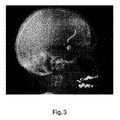
図3は、ビジュアライザVIZによって生成される一実施形態による視覚的出力を示す。上で簡単に説明されたように、視覚的インジケータVIは、高度に放射線不透過性物体によって引き起こされるストリークアーチファクトによって影響を受けると予測される投影領域を示す。更に、ビジュアライザVIZによって示される画像は、ユーザが、空間的配置の潜在的な調整を選択する際のガイダンスとして、アーチファクト投影と関心領域との交差領域を特定することを可能にする。 FIG. 3 shows the visual output according to one embodiment produced by the visualizer VIZ. As briefly described above, the visual indicator VI indicates a projected area that is expected to be affected by streak artifacts caused by highly radiopaque objects. In addition, the image presented by the visualizer VIZ allows the user to identify the intersection of the artifact projection and the region of interest as guidance in choosing a potential adjustment of spatial placement.
ユーザが回転面の様々な向き又は傾斜を選択し、それにより、調整された空間的配置を決定することができるグラフィカルユーザインターフェースGUIが提供されてよい。この結果、予測器AP及びビジュアライザVIZは協働して、適切に入力画像内の視覚的インジケータを更新し、視覚的指標は、関心領域と、新しく指定された回転面が投影画像の取得に使用されたならば現れうる再構成アーチファクトの投影との交差領域を示す。 A graphical user interface GUI may be provided that allows the user to select different orientations or tilts of the rotating surface, thereby determining a coordinated spatial arrangement. As a result, the predictor AP and the visualizer VIZ work together to properly update the visual indicators in the input image, and the visual indicators are used by the region of interest and the newly specified surface of revolution to obtain the projected image. Shows the area of intersection with the projection of the reconstructed artifact that can appear if done.
更新又は適応された視覚的インジケータが、現在の画像と共に表示されるか、又は、新しく指定された撮像幾何学的配置における新しい投影画像が取得され、適応された視覚的インジケータが、新しく取得された画像と共に表示される。 An updated or adapted visual indicator is displayed with the current image, or a new projected image in the newly specified imaging geometry is acquired and the adapted visual indicator is newly acquired. Displayed with the image.
撮像幾何学的配置アジャスタPAが、所定の関心領域へのストリークアーチファクトによる外乱が軽減又は低減されるように、例えば回転面の向き、方向又は傾斜の調整を決定する。より具体的には、調整された撮像幾何学的配置が選択され実現されると、予測された投影領域と関心領域に対応する領域との幾何学的交差度が減少される。 The imaging geometric placement adjuster PA determines, for example, the orientation, orientation or tilt of the surface of revolution so that disturbances due to streak artifacts to a given region of interest are reduced or reduced. More specifically, when the adjusted imaging geometry is selected and realized, the geometric intersection of the predicted projection region with the region corresponding to the region of interest is reduced.
アジャスタPAは、1つ以上の調整された撮像幾何学的配置のシミュレーション決定を行い、続いて、撮像幾何学的配置の実際の調整を実現するように、1つ以上のシステムコンポーネントの物理的な調整も制御する。 The adjuster PA makes simulation decisions for one or more adjusted imaging geometries, followed by the physical adjustment of one or more system components to achieve the actual adjustment of the imaging geometry. It also controls adjustments.
一実施形態では、予測器APは、したがって、シミュレーションされた調整された空間的配置での再構成アーチファクトの更新された投影領域を決定する。予測及び調整の決定は、所望の幾何学的配置が見つかるまで繰り返される。 In one embodiment, the predictor AP therefore determines the updated projected area of the reconstructed artifact in a simulated, coordinated spatial arrangement. Prediction and adjustment decisions are repeated until the desired geometry is found.
したがって、撮像システムのコンポーネントの物理的な動作、例えばCアームの動作は、例えば関心領域内の再構成アーチファクトが低減される回転面である所望の撮像幾何学的配置が特定された後にのみ必要である。 Therefore, the physical movement of the components of the imaging system, such as the C-arm, is required only after the desired imaging geometry has been identified, eg, a surface of revolution where reconstruction artifacts within the region of interest are reduced. is there.
入力ポート、ビジュアライザ、アジャスタ及びグラフィカルユーザインターフェースといった上記コンポーネントは、汎用コンピュータといったデータ処理ユニットPU上のソフトウェアルーチンとして動作する機能モジュールとして実現される。例えばソフトウェアルーチンは、イメージャIM又はネットワーク接続されたイメージャのグループに関連付けられるワークステーション上で動作する。ソフトウェア以外でのコンポーネントの実現も想定され、フィールドプログラマブルゲートアレイ(FPGA)又は集積回路(IC)等が含まれる。 The above components such as an input port, a visualizer, an adjuster, and a graphical user interface are realized as functional modules that operate as software routines on a data processing unit PU such as a general-purpose computer. For example, software routines run on workstations associated with imager IMs or groups of networked imagers. Realization of components other than software is also envisioned, and includes field programmable gate arrays (FPGAs), integrated circuits (ICs), and the like.
図3に示される投影領域の視覚的指標は、ほぼひし形又はダイアモンドの形状を有する。この形状は、図4及び図5を参照して以下に更に説明されるように、投影領域が計算される方法の結果である。しかし、視覚的インジケータの他の形状も本明細書では想定される。しかし、好適には、投影領域の視覚的インジケータVIは、ストリークアーチファクトの主な向き又は主な方向をユーザに直観的に示すことができるような方向成分を有する。放射線不透過性要素のフットプリントも、図3に示されるように円形模様として図示されるが、他の形状も想定される。図3を引き続き参照することにより理解できるように、一実施形態における視覚的インジケータは、コンパス針の外観を有する。しかし、本明細書では、方向を符号化可能である他の示唆的なシンボル体系も想定される。更に、視覚的指標VIは、背景とは違うように色が付けられてレンダリングされてもよい。他の実施形態では、視覚的インジケータVIは、下にある画像情報の遮断を最小限に抑えるために、ストリークアーチファクトによって影響を受ける領域の輪郭のみを描いてもよい。 The visual index of the projected area shown in FIG. 3 has a nearly diamond or diamond shape. This shape is the result of a method in which the projected area is calculated, as further described below with reference to FIGS. 4 and 5. However, other shapes of visual indicators are also envisioned herein. However, preferably, the projected area visual indicator VI has a directional component that allows the user to intuitively indicate the main orientation or main orientation of the streak artifact. The footprint of the radiation opaque element is also illustrated as a circular pattern as shown in FIG. 3, but other shapes are also envisioned. As can be understood by continuing to refer to FIG. 3, the visual indicator in one embodiment has the appearance of a compass needle. However, other suggestive symbolic schemes that can encode directions are also envisioned herein. In addition, the visual indicator VI may be rendered in a different color than the background. In other embodiments, the visual indicator VI may only outline the area affected by the streak artifact in order to minimize blocking of the underlying image information.
同じ色を使用するのではなく、高度に不透過性の物体のセグメンテーション自体に、投影領域を示すシンボル体系に使用される色とは異なる色が付けられてもよい。 Rather than using the same color, the segmentation itself of a highly opaque object may be colored differently than the color used for the symbol system to indicate the projected area.
次に、図4及び図5をより詳細に参照する。図4及び図5は、投影領域予測器APの動作の説明図である。具体的には、図4及び図5は、予測されるアーチファクトの影響を受ける投影領域の形状及び/又は範囲を計算するための基礎となるアルゴリズムステップを説明する。この段階において、回転面との関連で同じ幾何学的配置を呼び戻すことが有用である。X線幾何学的配置が、投影画像取得中になぞられる軌道を決定する。単純にするために、この軌道は円形であると想定する。X線源XRの焦点から検出器Dの中心までの仮想線が画定される。円形軌道中にこの線が辿られると、回転面内に仮想円盤が画定される。円形軌道上の位置から撮られた任意のX線投影画像について、仮想円盤は、(例えばCBCTによって取得された画像といった)X線投影画像上に線として投影される。この線が、再構成において、放射線不透過性物体によって引き起こされうるストリークアーチファクトの主な向きを規定する。画像内のROIに対するこの線の進行方向が、撮像幾何学的配置を変更する、例えば回転面を変更する又は患者支持体Cの位置/傾斜を変更することによって変えられる。 Next, FIGS. 4 and 5 will be referred to in more detail. 4 and 5 are explanatory views of the operation of the projection area predictor AP. Specifically, FIGS. 4 and 5 describe the underlying algorithmic steps for calculating the shape and / or range of the projected area affected by the predicted artifact. At this stage, it is useful to recall the same geometry in relation to the surface of revolution. The X-ray geometry determines the trajectory traced during the projection image acquisition. For simplicity, we assume that this orbit is circular. A virtual line is defined from the focal point of the X-ray source XR to the center of the detector D. When this line is traced in a circular orbit, a virtual disk is defined in the surface of revolution. For any X-ray projected image taken from a position on the circular orbit, the virtual disk is projected as a line on the X-ray projected image (eg, an image acquired by CBCT). This line defines the main orientation of streak artifacts that can be caused by radiation opaque objects in the reconstruction. The direction of travel of this line with respect to the ROI in the image is changed by changing the imaging geometry, eg, changing the surface of revolution or changing the position / tilt of the patient support C.
次に、図4A)を最初に参照する。図4A)は、説明し易くするために、今度は、垂直方向ではなく水平方向に示される回転面の図を示す。軌道t上のX線源XRの各位置について、放射線は、焦点から軌道上の所与の位置にある検出器に向けて放出される放射線rに沿って伝搬するものと見なされる。放射線は、周囲空間内に対応するコーンを形成する。 Next, FIG. 4A) is first referred to. FIG. 4A), for ease of explanation, now shows a view of the surface of revolution shown in the horizontal direction rather than in the vertical direction. For each position of the X-ray source XR on orbit t, the radiation is considered to propagate along the radiation r emitted from the focal point towards the detector at a given position on the orbit. Radiation forms a corresponding cone in the surrounding space.
例えば金属物体mを通過する放射線rのいずれもが、3D再構成においてストリークアーチファクトを引き起こす可能性がある。図4B)に示されるように、単一の投影画像は、金属物体mが正確にどこにあるのかを決定するには十分な情報を提供しないが、少なくとも当該物体を含むボリュームV(コーンセグメント)が決定される。 For example, any radiation r passing through a metal object m can cause streak artifacts in 3D reconstruction. As shown in FIG. 4B), a single projected image does not provide enough information to determine exactly where the metal object m is, but at least the volume V (cone segment) containing that object It is determined.
図5C)に示されるように、物体mの3D位置の推定値として上記ボリュームVの位置を所与として、このボリュームVを通るすべての可能なストリーク経路rの決定するのは単純な幾何学的配置の問題である。 As shown in FIG. 5C), given the position of the volume V as an estimate of the 3D position of the object m, it is a simple geometry to determine all possible streak paths r through this volume V. It's a matter of placement.
図5D)に示されるように、これらの経路II(r)と物体mのフットプリントII(m)とを一緒に入力画像面上に順投影すると、予測されるアーチファクトの影響を受ける領域の定義が提供される。改良として、この領域の幾何学的な覆い(hull)を作成して視覚的インジケータVIが画定される。図4B)から、(十分に離れた角度において取得された)2つ以上の投影画像を使用して位置ボリュームVを縮小し、これにより、予測の精度が向上されることは明らかであろう。アーチファクトの影響を受ける領域は、入力画像と共に、又は、新しい撮像幾何学的配置において取得された新しい画像と共に表示される。 As shown in FIG. 5D), the definition of the region affected by the predicted artifact when these paths II (r) and the footprint II (m) of the object m are projected forward together on the input image plane. Is provided. As an improvement, a geometric hull in this area is created to define the visual indicator VI. From FIG. 4B), it will be clear that the position volume V is reduced using two or more projected images (obtained at a sufficiently distant angle), which improves the accuracy of the prediction. The area affected by the artifact is displayed with the input image or with the new image acquired in the new imaging geometry.
要約すると、また、図5D)に示されるように、再構成アーチファクトによって影響を受けると予測される領域は、高度に放射線不透過性物体と、物体の推定位置を通る個々の放射線の投影との組み合わせられた投影フットプリントによって形成される。これらの個々のフットプリントの組み合わせ、即ち、集合体は、再構成アーチファクトを示す投影領域がそこから作成可能である領域を形成する。一実施形態では、予測されるアーチファクトの影響を受ける領域の境界が、組み合わせられた投影フットプリントの周りの包絡線(例えば凸包)によって画定される。 In summary, and as shown in Figure 5D), the regions predicted to be affected by the reconstructive artifacts are highly radiation-impermeable objects and projections of individual radiation through the estimated position of the object. Formed by a combined projection footprint. The combination of these individual footprints, or aggregates, forms a region from which a projected region representing the reconstructed artifact can be created. In one embodiment, the boundaries of the area affected by the predicted artifact are defined by envelopes (eg, convex hulls) around the combined projection footprint.
一実施形態において、放射線不透過性要素のフットプリント上の任意の境界画素から予測領域を画定するための更なる改良として、ストリークの範囲が、主な向きのベクトルと、放射線不透過性物体のフットプリントとの交差の長さとを使用して予測される。交差の長さは、主な向きのベクトルに沿ってこの境界点を通る線の放射線不透過性物体のフットプリントmとの交差によって画定される。このように、入力投影画像内のストリークによって影響を受ける領域が予測される。これの視覚化は、図3の視覚インジケータVIと同様である。つまり、可能な位置ボリュームVを通過する所与の放射線rの最終予測領域への寄与が、推定される交差の長さによって重み付けされる。当該寄与の重み付けは、様々な色/グレイ値又は不透過度によって図でレンダリングされる。これは、物体mの位置ボリュームVを通る経路長に依存して、重み関数によって実現される。例えば1mmの金属を通過する放射線は、10mmの金属を通過する放射線と同じ影響を有さない。「影響」とは、視覚的な知覚可能性を意味し、放射線は、これにより、再構成アーチファクトに寄与する。ある時点で、光子情報は完全になくなる(starved off)されるので、重み付け関数は必ずしも推定される長さに比例する必要はない。例えば30mmの経路長は、60mmと全く同じ影響を有する。つまり、重み関数は、重み関数がその点以降は一定のままであるカットオフ長さまで位置ボリュームVを通る経路長と(必ずしも線形ではないが)比例する。 In one embodiment, as a further improvement for defining the predicted region from any boundary pixel on the footprint of the radiation opaque element, the streak range is the vector of the main orientation and the radiation opaque object. Predicted using the length of intersection with the footprint. The length of the intersection is defined by the intersection of the line passing through this boundary point along the vector of the main orientation with the footprint m of the radiation opaque object. In this way, the region affected by the streak in the input projected image is predicted. The visualization of this is similar to the visual indicator VI of FIG. That is, the contribution of a given radiation r passing through the possible position volume V to the final prediction region is weighted by the estimated length of the intersection. The weighting of the contribution is rendered graphically with various color / gray values or opacity. This is achieved by a weighting function, depending on the length of the path through the position volume V of the object m. For example, radiation passing through a 1 mm metal does not have the same effect as radiation passing through a 10 mm metal. "Effect" means visual perceptibility, and radiation thereby contributes to the reconstructive artifacts. At some point, the photon information is starved off, so the weighting function does not necessarily have to be proportional to the estimated length. For example, a path length of 30 mm has exactly the same effect as 60 mm. That is, the weighting function is proportional (although not necessarily linear) to the path length through the position volume V up to the cutoff length at which the weighting function remains constant after that point.
次に、図4及び図5において説明されたように、予測投影領域が確立されると、一実施形態では、予測領域の視覚的指標VIが、表示ユニットMTに図でレンダリングされる。そうすると、ユーザは、アーチファクトが所定の関心領域ROI内に延在するか又は重なるかを視覚的に調べることができる。 Next, as described in FIGS. 4 and 5, once the predicted projection area is established, in one embodiment, the visual index VI of the predicted area is rendered graphically on the display unit MT. The user can then visually inspect whether the artifacts extend or overlap within a given region of interest ROI.
或いは、この評価は、アジャスタPAによって自動的に行われる。 Alternatively, this evaluation is automatically performed by the adjuster PA.
アーチファクトの投影と関心領域ROIとに重なりがない又は適切に縮小されているとすぐに、ユーザは、続けて、CBCTスキャンに必要な投影画像を取得するようにイメージャIMを作動させる。取得された投影画像は、再構成部に転送され、ボリュメトリック画像を生成するための再構成が開始される。 As soon as the projection of the artifact and the region of interest ROI do not overlap or are adequately reduced, the user subsequently activates the imager IM to acquire the projected image required for the CBCT scan. The acquired projected image is transferred to the reconstruction unit, and reconstruction for generating a volumetric image is started.
しかし、評価が、再構成アーチファクトはROIにおける画質を許容不可能なレベルで損なうことを示すと、提案されるシステムIPSは、視覚的指標VIに基づいて、再構成用の投影画像がそこで収集されるべき新しい撮像幾何学的配置をユーザが選択することを可能にする。新しい撮像幾何学的配置は、回転面と平行な軸の周りに回転面を回転させることによって、又は、撮像物体Pがその上にある支持体Cを移動若しくは傾斜させることによって、上記されたように得られる。 However, the evaluation shows that the reconstruction artifacts impair the image quality in the ROI at an unacceptable level, the proposed system IPS is based on the visual indicator VI, where projection images for reconstruction are collected. Allows the user to choose a new imaging geometry to be. The new imaging geometry is as described above by rotating the surface of revolution around an axis parallel to the surface of revolution, or by moving or tilting the support C on which the imaging object P is placed. Obtained in.
上記されたように、調整された撮像幾何学的配置は、撮像幾何学的配置アジャスタPAによって自動的に選択されてもよい。この場合、予測器APは、アジャスタPAから(シミュレーションされた)調整された幾何学的配置を受信し、これにより、新しい幾何学的配置による再構成アーチファクトが予測され、後続の評価に使用される。したがって、反復処理において、アーチファクト投影と関心領域との最小限の交差が決定される。 As mentioned above, the adjusted imaging geometry may be automatically selected by the imaging geometry adjuster PA. In this case, the predictor AP receives the adjusted (simulated) geometry from the adjuster PA, which predicts the reconstructed artifacts with the new geometry and is used for subsequent evaluations. .. Therefore, in the iterative process, the minimum intersection between the artifact projection and the region of interest is determined.
より具体的には、傾斜軌道を実現するために、別の回転軸が規定されてもよい。この傾斜軌道は、回転中にX線システムの角度を変えることによって傾斜軌道をもたらすか、又は、患者台を傾斜させることによって実現される。傾斜軌道は依然として治療中心を通過する。傾斜角は、ユーザによって又は自動的に選択される。 More specifically, another axis of rotation may be defined to achieve an inclined orbit. This tilted orbit is achieved by changing the angle of the X-ray system during rotation to provide a tilted orbit or by tilting the patient table. Inclined orbit still passes through the treatment center. The tilt angle is selected by the user or automatically.
新しい回転面の自動決定の実施形態において、ROI(例えばステント)は、適切なアルゴリズムによって自動的に又は半自動的にセグメント化される。ROIは、事前のCBCT画像といった入力画像内、又は、CアームシステムのX線写真内でセグメント化される。回転軌道の現在の回転面の回転軸は、ストリークがセグメント化されたROIと交差しなくなるまで、適切な一定量で、ループで変更される。例えばROI内に最も少ないストリークをもたらす回転面が選択される。この基準に適合する回転面が複数ある場合は、変更が最も少ない回転面が選択される。例えば現在の回転面の傾斜角は、より良い回転軸を見つけるために、ストリーク投影領域とROIとの交差領域がどのように変化するのかを調べつつ、現在の回転軸を徐々に回転させることによって変更される。 In an embodiment of automatic determination of the new surface of revolution, ROIs (eg, stents) are segmented automatically or semi-automatically by appropriate algorithms. The ROI is segmented within an input image, such as a pre-CBCT image, or within a radiograph of the C-arm system. The axis of rotation of the current surface of revolution of the rotating orbit is changed in a loop by an appropriate constant amount until the streak no longer intersects the segmented ROI. For example, the surface of revolution that produces the least streak in the ROI is selected. If there are multiple surface of revolutions that meet this criterion, the surface of revolution with the least changes is selected. For example, the tilt angle of the current surface of revolution can be determined by gradually rotating the current axis of rotation while investigating how the intersection region of the streak projection area and the ROI changes in order to find a better axis of rotation. Be changed.
今度は、手動の実施形態を参照するに、次の変形態様が想定される。一実施形態では、ユーザは、傾斜角を数値的に入力する。或いは、コンピュータマウスといった入力ツールを使用して、例えばリスト等から傾斜角度値を選択することによって、軌道の傾斜が変更される。ユーザがマウス又は他の入力ツールを使用して入力画像内に、X線画像の平面との回転面の交差の所望の向き及び位置を示す線を描く図を使った幾何学的入力も想定される。 This time, with reference to the manual embodiment, the following modifications are envisioned. In one embodiment, the user inputs the tilt angle numerically. Alternatively, the inclination of the trajectory is changed by using an input tool such as a computer mouse and selecting an inclination angle value from a list or the like, for example. Geometric input is also envisioned using a diagram in which the user draws a line in the input image using a mouse or other input tool to show the desired orientation and position of the intersection of the plane of revolution with the plane of the X-ray image. To.
次に、図6を参照する。図6は、例えばグラフィカルユーザインターフェースGUIである適切なユーザインターフェースの例示的な実施形態を示す。破線は、ユーザによって指定される画像の平面との回転面の交差を示す。この指定は、その他の点では知られている方法で2つの点を指定することによって新しい交差線を規定するようにコンピュータマウスを使用することによってユーザによってインタラクティブに規定される。別のオプションは、タッチスクリーンを使用することであり、ユーザは、新しい回転面の交差線を規定するために、指タッチ指示を使用する。タッチスクリーンインタラクションを使用する場合、ユーザは、指をスクリーン上で1つの位置から別の位置までドラッグさせることによってスクリーン上に新しい交差線を書くか、又は、ユーザは、単に2つの点を指定し、システムが、そこから交差線を自動的に補間してもよい。本明細書では、他のグラフィカル又は非グラフィカル入力機構も想定される。 Next, refer to FIG. FIG. 6 shows an exemplary embodiment of a suitable user interface, for example a graphical user interface GUI. The dashed line indicates the intersection of the plane of revolution with the plane of the image specified by the user. This designation is interactively defined by the user by using a computer mouse to define a new intersection by designating the two points in a manner known otherwise. Another option is to use a touch screen, where the user uses finger touch instructions to define the intersection of the new surface of revolution. When using touch screen interactions, the user either draws a new intersection on the screen by dragging his finger from one position to another on the screen, or the user simply specifies two points. , The system may automatically interpolate the intersections from there. Other graphical or non-graphical input mechanisms are also envisioned herein.
ユーザが新しい回転面を指定した後、システムIPSは、イベントハンドラによって捕捉される適切なコマンド又はイベントを出す。イベントハンドラは、次に、予測器APに、今度は、新しく画定された回転面に基づいて投影領域を再予測するように命令し、当該投影領域は、現在表示されている投影領域指標マークVIの代わりに、ビジュアライザVIZによって画面に表示される。したがって、ユーザは、システムを用いて「実験」を行い、現在の撮像幾何学的配置よりも少ない度合いでROIに影響を及ぼすアーチファクトの向き又は範囲をもたらす適切な回転面を見つけることができる。 After the user specifies a new surface of revolution, the system IPS issues the appropriate command or event captured by the event handler. The event handler then commands the predictor AP to repredict the projection area, this time based on the newly defined surface of revolution, which is the currently displayed projection area indicator mark VI. Instead of being displayed on the screen by the visualizer VIZ. Therefore, the user can "experiment" with the system to find a suitable surface of revolution that provides an orientation or range of artifacts that affect the ROI to a lesser extent than the current imaging geometry.
或いは、また、上記実施形態とは対照的に、ユーザが、入力X線画像内にストリークアーチファクトの要な向きを、図を使用して又は他の方法で指定してもよい。この場合、システムは、指定されたストリークの主な向きに関連付けられる必要な撮像幾何学的配置の変更を計算する。 Alternatively, in contrast to the above embodiment, the user may specify the required orientation of the streak artifact in the input X-ray image using a diagram or in other ways. In this case, the system calculates the necessary imaging geometry changes associated with the main orientation of the specified streak.
上記されたように、満足のいく撮像幾何学的配置が見つかると、撮像装置IMは、指定された撮像幾何学的配置において必要な投影画像を取得し始める。この撮像幾何学的配置における撮像取得は、自動的に、又は、ユーザが操作コンソールOCから適切な制御信号を出した後にトリガされる。 As mentioned above, once a satisfactory imaging geometry is found, the imaging device IM begins to acquire the required projected image in the specified imaging geometry. Imaging acquisition in this imaging geometry is triggered automatically or after the user issues an appropriate control signal from the operating console OC.
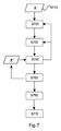
次に、図7のフローチャートを参照する。図7は、図1の画像処理システムによって実施される画像処理方法を示す。しかし、当然ながら、方法ステップに関する以下の説明は、図1の構造に必ずしも縛られない。つまり、以下の方法ステップは、それ自体で1つの教示内容を構成する。 Next, the flowchart of FIG. 7 is referred to. FIG. 7 shows an image processing method implemented by the image processing system of FIG. However, of course, the following description of method steps is not necessarily bound by the structure of FIG. That is, the following method step itself constitutes one teaching content.
ステップS710において、撮像物体Pの単一又は2つ以上の入力投影画像が受信される。画像は、回転撮像装置IMによって取得される。入力投影画像は、撮像領域の周りの現在の回転面における撮像軌道上の位置において取得される。或いは、CT設定では、複数の投影画像から編集されるスカウト画像が入力画像として使用される。 In step S710, a single or two or more input projection images of the imaged object P are received. The image is acquired by the rotary imager IM. The input projected image is acquired at a position on the imaging trajectory on the current rotating surface around the imaging region. Alternatively, in the CT setting, a scout image edited from a plurality of projected images is used as the input image.
ステップS720において、当該入力画像について、投影領域が予測される。予測は、現在の回転面による現在の幾何学的配置に基づいている。投影領域は、再構成アーチファクトの範囲又は主な方向を規定する。再構成アーチファクトは、現在の撮像幾何学的配置において取得される投影データに基づいて再構成が行われたならば生じるアーチファクトである。アーチファクトは、撮像領域内に金属物体といった高度に不透過性の物体mが存在することにより再構成において引き起こされる。 In step S720, the projection area is predicted for the input image. The prediction is based on the current geometry of the current surface of revolution. The projected area defines the extent or main direction of the reconstructed artifact. Reconstruction artifacts are artifacts that would occur if reconstruction was performed based on the projection data obtained in the current imaging geometry. The artifact is caused in the reconstruction by the presence of a highly opaque object m, such as a metal object, in the imaging region.
一実施形態では、予測は、高度に不透過性の物体mのフットプリントのセグメンテーションに基づいている。入力X線画像内の放射線不透過性物体のフットプリントは、画像値閾値化を適用することによって見つけられる。物体のサイズもストリークアーチファクトに影響を及ぼすので、追加の基準を使用して、特定の最小限のサイズの物体フットプリントのみがセグメント化される。或いは、見つかった物体のサイズに基づいて閾値を適応させる関数が使用されてもよい。更に或いは、例えば流域アルゴリズム、領域拡張、手動注釈付け、図の切り出し等である他のセグメンテーションアプローチを使用してもよい。更なる代案として、高度に放射線不透過性物体のフットプリントは、事前CT又はCBCTにおいてセグメント化され、当該セグメンテーションは、入力2DX線画像上に順投影される。 In one embodiment, the prediction is based on segmentation of the footprint of a highly opaque object m. The footprint of a radiation opaque object in the input X-ray image can be found by applying image value thresholding. Object size also affects streak artifacts, so using additional criteria, only certain minimal sized object footprints are segmented. Alternatively, a function that adapts the threshold based on the size of the found object may be used. Alternatively, other segmentation approaches such as watershed algorithms, region expansion, manual annotation, diagram cropping, etc. may be used. As a further alternative, the footprint of highly radiopaque objects is segmented in pre-CT or CBCT, and the segmentation is forward-projected onto the input 2DX line image.
当該物体の位置ボリュームを通る放射線は、入力画像上に順投影され、物体mのフットプリントと組み合わされ、再構成においてアーチファクトによって影響を受ける可能性のある領域の定義が得られる。より具体的には、アーチファクトによって影響を受ける領域が、図4及び図5において説明されたように画定される。 Radiation passing through the position volume of the object is forward-projected onto the input image and combined with the footprint of the object m to provide a definition of the region that may be affected by the artifact in the reconstruction. More specifically, the regions affected by the artifact are defined as described in FIGS. 4 and 5.
動作ステップS730において、表示ユニット上で予測投影領域が視覚化される。 In operation step S730, the predicted projection area is visualized on the display unit.
ステップS740において、撮像幾何学的配置の変更の指定が決定され、これに応えて、任意選択的に、視覚的指標が適応される。一実施形態では、撮像物体に対する新しい回転面π’の指定は、新しい回転軸α’を指定することによって受信される。当該指定には回転面の提案される傾斜が含まれる。より一般的に、回転面の新しい回転軸が指定される。 In step S740, the designation of changing the imaging geometry is determined, and in response, the visual index is optionally applied. In one embodiment, the designation of a new surface of revolution π'for the imaged object is received by designating a new axis of rotation α'. The designation includes the proposed slope of the rotating surface. More generally, a new axis of rotation for the surface of revolution is specified.
変更は、予測投影領域と所定関心領域ROIに対応する画像内の領域との交差に依存して、自動的に、又は、ユーザによってリクエストされる。 Changes are requested automatically or by the user, depending on the intersection of the predicted projection area with the area in the image corresponding to the predetermined area of interest ROI.
指定には、或いは、撮像中に物体がその上に存在する支持体の傾斜又は移動が含まれてよい。 The designation may also include tilting or moving a support on which the object is present during imaging.
撮像幾何学的配置の変更の指定に応えて、先の予測ステップS720及び(任意選択的に)視覚化ステップS730が繰り返される。つまり、新しく決定された調整された撮像幾何学的配置に基づいて、アーチファクトの向き及び/又は拡張について新しく予測された領域の更新された視覚指標が計算される。更新又は適応された視覚化は、入力画像上、又は、新しく指定された撮像幾何学的配置において取得された新しい入力画像上に表示される。 The previous prediction step S720 and (optionally) the visualization step S730 are repeated in response to the designation of changing the imaging geometry. That is, based on the newly determined adjusted imaging geometry, updated visual indicators of the newly predicted region for the orientation and / or expansion of the artifact are calculated. The updated or adapted visualization is displayed on the input image or on the new input image acquired in the newly specified imaging geometry.
ステップS750において、決定された調整された撮像幾何学的配置が実現され、したがって、システムを新しい撮像幾何学的配置に従って再配置するように、1つ以上のシステムコンポーネントの動作が制御される。つまり、この幾何学的配置下で、この新しい幾何学的配置で収集された投影データから再構成する場合、ROIは、ストリークアーチファクトによる視覚的干渉が全くないか、又は、少なくともこの干渉はユーザが知覚できるレベルを下回る。最終の新しい幾何学的配置が見つかると、対応する投影領域は、ステップS740に従って視覚化される。 In step S750, the determined adjusted imaging geometry is achieved and therefore the behavior of one or more system components is controlled so that the system is rearranged according to the new imaging geometry. That is, under this geometry, when reconstructing from the projection data collected in this new geometry, the ROI will have no visual interference due to streak artifacts, or at least this interference will be caused by the user. Below a perceptible level. When the final new geometry is found, the corresponding projection area is visualized according to step S740.
ステップS760において、新しい幾何学的配置が設定されると、撮像装置は、当該新しい撮像幾何学的配置において投影画像を取得するように動作する。例えばX線源は、物体の周りの新しく調整された撮像面内の軌道上の異なる位置をなぞる。 When a new geometric arrangement is set in step S760, the image pickup device operates to acquire a projected image in the new imaging geometric arrangement. For example, the X-ray source traces different positions on the orbit within the newly adjusted imaging plane around the object.
ステップS770において、このように取得された投影画像は、適切な(分析的又は反復的)再構成アルゴリズムによって、物体、具体的には、関心領域の所望のボリュメトリック画像に再構成される。 In step S770, the projected image thus obtained is reconstructed into a desired volumetric image of the object, specifically the region of interest, by an appropriate (analytical or iterative) reconstruction algorithm.
要約するに、本明細書では、再構成された画像内のストリークアーチファクトを回避する又は少なくとも低減することが提案される。少なくとも1つの入力X線画像が、実際のスキャンの前に取得される。この入力画像内で、放射線不透過性領域が特定される。次に、計画された回転スキャンの軌道の知識に基づいて、計画された取得からの再構成におけるストリークの向きが予測される。この情報は、一実施形態では、好適には、入力X線画像内に、ユーザへの視覚的フィードバックとして提供される。当該情報に基づいて、新しい回転スキャン軌道が決定される。例えばユーザが別の回転軸を、図を使用して又は使用しないで指定する。対応して新しく提案されるスキャン軌道におけるストリークアーチファクトが再び予測され視覚化される。様々な傾斜角についてストリークアーチファクトをシミュレーションし、関心物体内のストリークが最も少ない傾斜角を選択することによって別の軌道も自動的に決定される。 In summary, it is proposed herein to avoid or at least reduce streak artifacts in the reconstructed image. At least one input X-ray image is acquired prior to the actual scan. Within this input image, a radiation opaque region is identified. The streak orientation in the reconstruction from the planned acquisition is then predicted based on the knowledge of the planned rotational scan trajectory. In one embodiment, this information is preferably provided as visual feedback to the user within the input x-ray image. Based on this information, a new rotational scan trajectory is determined. For example, the user specifies another axis of rotation with or without a diagram. Correspondingly, streak artifacts in the newly proposed scan trajectory are predicted and visualized again. Another trajectory is automatically determined by simulating streak artifacts for various tilt angles and selecting the tilt angle with the least streak in the object of interest.
本発明の別の例示的な実施形態では、上記実施形態のうちの1つによる方法のステップを適切なシステム上で実行するように適応されていることによって特徴付けられるコンピュータプログラム又はコンピュータプログラム要素が提供される。 In another exemplary embodiment of the invention, a computer program or computer program element characterized by being adapted to perform the steps of the method according to one of the above embodiments on a suitable system. Provided.
したがって、コンピュータプログラム要素は、コンピュータユニットに記憶されていてもよい。当該コンピュータユニットも、本発明の一実施形態の一部であってよい。当該コンピュータユニットは、上記方法のステップを行うか又はステップの実行を誘導する。更に、コンピュータユニットは、上記装置のコンポーネントを動作させる。コンピュータユニットは、自動的に動作するか及び/又はユーザの命令を実行する。コンピュータプログラムが、データプロセッサの作業メモリにロードされてよい。したがって、データプロセッサは、本発明の方法を実行する能力を備えている。 Therefore, the computer program element may be stored in the computer unit. The computer unit may also be part of an embodiment of the present invention. The computer unit either performs the steps of the above method or guides the execution of the steps. In addition, the computer unit operates the components of the device. The computer unit operates automatically and / or executes the user's instructions. The computer program may be loaded into the working memory of the data processor. Therefore, the data processor has the ability to carry out the methods of the invention.
本発明のこの例示的な実施形態は、最初から本発明を使用するコンピュータプログラムと、アップデートによって、既存のプログラムを、本発明を使用するプログラムに変えるコンピュータプログラムとの両方を対象とする。 This exemplary embodiment of the invention covers both a computer program that uses the invention from the beginning and a computer program that, by updating, transforms an existing program into a program that uses the invention.
更に、コンピュータプログラム要素は、上記方法の例示的な実施形態の手順を満たすすべての必要なステップを提供することができる。 In addition, the computer program element can provide all the necessary steps to meet the procedures of the exemplary embodiments of the above method.
本発明の更なる例示的な実施形態によれば、CD−ROMといったコンピュータ可読媒体が提示される。コンピュータ可読媒体に、コンピュータプログラム要素が記憶され、コンピュータプログラム要素は上記セクションに説明されている。 According to a further exemplary embodiment of the invention, a computer readable medium such as a CD-ROM is presented. Computer program elements are stored on a computer-readable medium, which are described in the section above.
コンピュータプログラムは、他のハードウェアと共に又は他のハードウェアの一部として供給される光学記憶媒体又は固体媒体といった適切な媒体(具体的には、必ずしもそうである必要はないが、非一時的媒体)上に記憶される及び/又は分散配置されるが、インターネット又は他の有線若しくは無線通信システムを介した形態といった他の形態で分配されてもよい。 The computer program is a suitable medium (specifically, but not necessarily, a non-temporary medium) such as an optical storage medium or a solid medium that is supplied with or as part of the other hardware. ) Stored and / or distributed, but may be distributed in other forms, such as via the Internet or other wired or wireless communication systems.
しかし、コンピュータプログラムは、ワールドワイドウェブといったネットワークを介して提示され、当該ネットワークからデータプロセッサの作業メモリにダウンロードされてもよい。本発明の更なる例示的な実施形態によれば、ダウンロード用にコンピュータプログラム要素を利用可能にする媒体が提供され、当該コンピュータプログラム要素は、本発明の上記実施形態のうちの1つによる方法を行うように構成される。 However, the computer program may be presented via a network such as the World Wide Web and downloaded from the network into the working memory of the data processor. A further exemplary embodiment of the invention provides a medium that makes a computer program element available for download, the computer program element being a method according to one of the above embodiments of the invention. Configured to do.
なお、本発明の実施形態は、様々な主題を参照して説明されている。具体的には、方法タイプのクレームを参照して説明される実施形態もあれば、デバイスタイプのクレームを参照して説明される実施形態もある。しかし、当業者であれば、上記及び下記の説明から、特に明記されない限り、1つのタイプの主題に属する特徴の任意の組み合わせに加えて、様々な主題に関連する特徴の任意の組み合わせも、本願によって開示されていると見なされると理解できるであろう。しかし、すべての特徴は、特徴の単なる足し合わせ以上の相乗効果を提供する限り、組み合わされることが可能である。 The embodiments of the present invention are described with reference to various subjects. Specifically, some embodiments are described with reference to method type claims, while others are described with reference to device type claims. However, one of ordinary skill in the art will appreciate any combination of features related to various subjects in addition to any combination of features belonging to one type of subject, unless otherwise specified, from the above and below description. It will be understood that it is considered to be disclosed by. However, all features can be combined as long as they provide a synergistic effect that goes beyond the mere addition of features.
本発明は、図面及び上記説明において詳細に例示され、説明されたが、当該例示及び説明は、例示的に見なされるべきであり、限定的に見なされるべきではない。本発明は、開示される実施形態に限定されない。開示された実施形態の他の変形態様は、図面、開示内容及び従属請求項の検討から、請求項に係る発明を実施する当業者によって理解され、実施される。 Although the present invention has been exemplified and described in detail in the drawings and the above description, the examples and description should be viewed as exemplary and not limited. The present invention is not limited to the disclosed embodiments. Other variations of the disclosed embodiments will be understood and implemented by those skilled in the art who will practice the claimed invention from the drawings, disclosure content and examination of the dependent claims.
請求項において、「含む」との用語は、他の要素又はステップを排除するものではなく、また、「a」又は「an」との不定冠詞も、複数形を排除するものではない。単一のプロセッサ又は他のユニットが、請求項に引用される幾つかのアイテムの機能を果たしてもよい。特定の手段が相互に異なる従属請求項に記載されることだけで、これらの手段の組み合わせを有利に使用することができないことを示すものではない。請求項における任意の参照符号は、範囲を限定するものと解釈されるべきではない。 In the claims, the term "contains" does not exclude other elements or steps, nor does the indefinite definite article "a" or "an" exclude the plural. A single processor or other unit may perform the function of some of the items cited in the claims. The fact that specific means are described in different dependent claims does not indicate that the combination of these means cannot be used advantageously. Any reference code in the claims should not be construed as limiting the scope.
Claims (15)
前記投影画像についての分かっている前記撮像軌道に基づく、前記投影画像に対するセグメンテーションにおいて得られる放射線不透過性物体のフットプリントの特定に基づいて、再構成アーチファクトの投影領域を入力画像内で幾何学的に予測する画像アーチファクト範囲予測器であって、予測は、前記放射線不透過性物体を含む放射線コーンセグメントを決定し、前記放射線コーンセグメントを通るすべての可能なストリーク経路と前記放射線不透過性物体の前記フットプリントとを一緒に入力画像面上に順投影することによる、前記撮像領域内に存在する放射線不透過性物体のフットプリントの特定に基づいている画像アーチファクト範囲予測器と、
予測された前記投影領域と前記投影画像内の所定関心領域に対応する領域との交差を減少させるように、前記第1の回転面と前記物体との相対的空間的配置の調整を決定する撮像幾何学的配置アジャスタと、
を含む、画像処理システム。 An input port that receives a projected image of an object acquired by a rotating imager at a position on the imaging trajectory on a first rotating surface around the imaging region.
Based on the known imaging trajectory of the projected image , the projected area of the reconstructed artifact is geometrically included in the input image based on the identification of the footprint of the radiation opaque object obtained in the segmentation of the projected image. An image artifact range predictor that predicts to determine the radiation cone segment containing the radiation opaque object and all possible streak paths through the radiation cone segment and of the radiation opaque object. An image artifact range predictor based on identifying the footprint of a radiation opaque object present in the imaging region by forward-projecting the footprint together onto the input image plane.
Imaging that determines the adjustment of the relative spatial arrangement of the first rotating surface and the object so as to reduce the intersection of the predicted projected region with the region of interest in the projected image. Geometric arrangement adjuster and
Image processing system, including.
投影画像を取得する撮像装置と、
ビジュアライザから画像情報を受信して表示する表示ユニットと、
を含む、撮像アレンジメント。 The image processing system according to any one of claims 1 to 7.
An image pickup device that acquires a projected image and
A display unit that receives and displays image information from the visualizer,
Imaging arrangements, including.
前記投影画像についての分かっている前記撮像軌道に基づく、前記投影画像に対するセグメンテーションにおいて得られる放射線不透過性物体のフットプリントの特定に基づいて、再構成アーチファクトの投影領域を入力画像内で幾何学的に予測するステップであって、予測は、前記放射線不透過性物体を含む放射線コーンセグメントを決定し、前記放射線コーンセグメントを通るすべての可能なストリーク経路と前記放射線不透過性物体の前記フットプリントとを一緒に入力画像面上に順投影することによる、前記撮像領域内に存在する放射線不透過性物体のフットプリントの特定に基づくステップと、
予測された前記投影領域と前記投影画像内の所定関心領域に対応する領域との交差を減少させるように、前記回転面と前記物体との相対的空間的配置の調整を決定するステップと、
を含む、画像処理の方法。 A step of receiving a projected image of an object acquired by a rotating imager at a position on the imaging trajectory on an adjustable surface of revolution around the imaging region.
Based on the known imaging trajectory of the projected image , the projected area of the reconstructed artifact is geometrically included in the input image based on the identification of the footprint of the radiation opaque object obtained in the segmentation of the projected image. In the step of predicting, the prediction determines the radiation cone segment containing the radiation opaque object and includes all possible streak paths through the radiation cone segment and the footprint of the radiation opaque object. A step based on the identification of the footprint of a radiation opaque object present in the imaging region by forward-projecting together on the input image plane.
A step of determining the adjustment of the relative spatial arrangement of the surface of revolution and the object so as to reduce the intersection of the predicted region of interest with the region of interest in the projected image.
A method of image processing, including.
取得された前記投影画像から、少なくとも前記所定関心領域のボリュメトリック画像を再構成するステップと、
を更に含む、請求項12に記載の方法。 A step of manipulating the imaging device to acquire projected images at different positions on the orbit according to the adjusted relative spatial arrangement of the rotating surface and the object.
A step of reconstructing a volumetric image of at least the predetermined region of interest from the acquired projected image, and
12. The method of claim 12.
Applications Claiming Priority (3)
| Application Number | Priority Date | Filing Date | Title |
|---|---|---|---|
| EP15200072.5 | 2015-12-15 | ||
| EP15200072 | 2015-12-15 | ||
| PCT/EP2016/081073 WO2017102887A1 (en) | 2015-12-15 | 2016-12-14 | Streak artifact prediction |
Publications (3)
| Publication Number | Publication Date |
|---|---|
| JP2018537224A JP2018537224A (en) | 2018-12-20 |
| JP2018537224A5 JP2018537224A5 (en) | 2020-07-27 |
| JP6797920B2 true JP6797920B2 (en) | 2020-12-09 |
Family
ID=55024790
Family Applications (1)
| Application Number | Title | Priority Date | Filing Date |
|---|---|---|---|
| JP2018530823A Active JP6797920B2 (en) | 2015-12-15 | 2016-12-14 | Streak artifact prediction |
Country Status (5)
| Country | Link |
|---|---|
| US (1) | US10803632B2 (en) |
| EP (1) | EP3391341A1 (en) |
| JP (1) | JP6797920B2 (en) |
| CN (1) | CN108369745B (en) |
| WO (1) | WO2017102887A1 (en) |
Families Citing this family (8)
| Publication number | Priority date | Publication date | Assignee | Title |
|---|---|---|---|---|
| US11419566B2 (en) * | 2017-11-14 | 2022-08-23 | General Electric Company | Systems and methods for improving image quality with three-dimensional scout |
| DE102018211106A1 (en) * | 2018-07-05 | 2020-01-09 | Siemens Healthcare Gmbh | Method for reducing an artifact in a computed tomography image data set |
| EP3618001A1 (en) * | 2018-08-30 | 2020-03-04 | Koninklijke Philips N.V. | Efficient motion-compensation in cone beam computed tomography based on data consistency |
| US20220071578A1 (en) * | 2018-12-30 | 2022-03-10 | Carestream Dental Llc | Improved method of acquiring a radiographic scan of a region-of-interest in a metal containing object |
| EP3705046A1 (en) * | 2019-03-07 | 2020-09-09 | Koninklijke Philips N.V. | Apparatus for determining a control protocol for controlling a c-arm system |
| CN112399223B (en) * | 2019-08-18 | 2022-11-29 | 海信视像科技股份有限公司 | Method for improving moire fringe phenomenon and display device |
| US11357466B2 (en) * | 2019-10-02 | 2022-06-14 | Canon Medical Systems Corporation | X-ray diagnosis apparatus |
| CN113269733B (en) * | 2021-05-14 | 2024-04-16 | 成都真实维度科技有限公司 | Artifact detection method for radioactive particles in tomographic image |
Family Cites Families (23)
| Publication number | Priority date | Publication date | Assignee | Title |
|---|---|---|---|---|
| JP3707347B2 (en) | 2000-04-07 | 2005-10-19 | 株式会社島津製作所 | Image processing method for X-ray CT apparatus, X-ray CT apparatus, and recording medium for X-ray CT imaging |
| JP2003135450A (en) * | 2001-10-31 | 2003-05-13 | Yoshihiko Nomura | Method for reducing artifacts in x-ray ct reconstructed image |
| US6816571B2 (en) | 2002-02-06 | 2004-11-09 | L-3 Communications Security And Detection Systems Corporation Delaware | Method and apparatus for transmitting information about a target object between a prescanner and a CT scanner |
| US6961404B2 (en) * | 2002-09-26 | 2005-11-01 | Eastman Kodak Company | Method and system for reconstructing an image from projection data acquired by a cone beam computed tomography system |
| US20060039537A1 (en) * | 2004-05-28 | 2006-02-23 | Strobel Norbert K | C-arm device with adjustable detector offset for cone beam imaging involving partial circle scan trajectories |
| WO2007127161A1 (en) * | 2006-04-25 | 2007-11-08 | Wisconsin Alumni Research Foundation | System and method for estimating data missing from ct imaging projections |
| DE102006041033B4 (en) * | 2006-09-01 | 2017-01-19 | Siemens Healthcare Gmbh | Method for reconstructing a three-dimensional image volume |
| US8023767B1 (en) * | 2008-03-10 | 2011-09-20 | University Of Rochester | Method and apparatus for 3D metal and high-density artifact correction for cone-beam and fan-beam CT imaging |
| WO2010038195A2 (en) * | 2008-09-30 | 2010-04-08 | Lodox Systems (Proprietary) Limited | Method and system for removing butting or stitching artifacts from images |
| JP5324883B2 (en) * | 2008-10-24 | 2013-10-23 | アズビル株式会社 | CT apparatus and metal shape extraction method |
| US8819591B2 (en) | 2009-10-30 | 2014-08-26 | Accuray Incorporated | Treatment planning in a virtual environment |
| JP5808734B2 (en) * | 2010-02-26 | 2015-11-10 | 株式会社日立メディコ | X-ray imaging device |
| US10430981B2 (en) | 2010-10-27 | 2019-10-01 | Koninklike Philips N.V. | Image artifact identification and mitigation |
| EP2716226A4 (en) | 2011-05-31 | 2014-11-05 | Shimadzu Corp | Radiation tomographic image generation method and radiation tomographic image generation program |
| US9202296B2 (en) | 2011-09-16 | 2015-12-01 | Caresteam Health, Inc. | Metal artifacts reduction for cone beam CT |
| WO2013056733A1 (en) * | 2011-10-19 | 2013-04-25 | Siemens Aktiengesellschaft | Out of plane artifact reduction in digital breast tomosynthesis and ct |
| JP6144268B2 (en) * | 2011-10-24 | 2017-06-07 | コーニンクレッカ フィリップス エヌ ヴェKoninklijke Philips N.V. | Motion compensated second pass metal artifact correction for CT slice images |
| CN104602606B (en) | 2012-08-31 | 2017-06-23 | 株式会社岛津制作所 | Radioactive ray faultage image generating means and radioactive ray tomographic image generation method |
| US9380275B2 (en) * | 2013-01-30 | 2016-06-28 | Insitu, Inc. | Augmented video system providing enhanced situational awareness |
| CN105246402B (en) | 2013-03-08 | 2018-10-02 | 光学实验室成像公司 | Holder visualizes and adherent bad detecting system, device and method |
| JP6294008B2 (en) * | 2013-05-22 | 2018-03-14 | キヤノンメディカルシステムズ株式会社 | X-ray computed tomography apparatus, reconstruction processing method, and reconstruction processing program |
| CN103617598B (en) * | 2013-11-10 | 2016-08-31 | 北京工业大学 | A kind of CT image metal artifact minimizing technology based on track |
| US9592020B2 (en) * | 2014-06-23 | 2017-03-14 | Palodex Group Oy | System and method of artifact correction in 3D imaging |
-
2016
- 2016-12-14 CN CN201680073864.3A patent/CN108369745B/en active Active
- 2016-12-14 US US16/062,068 patent/US10803632B2/en active Active
- 2016-12-14 JP JP2018530823A patent/JP6797920B2/en active Active
- 2016-12-14 WO PCT/EP2016/081073 patent/WO2017102887A1/en active Application Filing
- 2016-12-14 EP EP16822630.6A patent/EP3391341A1/en active Pending
Also Published As
| Publication number | Publication date |
|---|---|
| US20180365869A1 (en) | 2018-12-20 |
| WO2017102887A1 (en) | 2017-06-22 |
| CN108369745B (en) | 2023-11-07 |
| EP3391341A1 (en) | 2018-10-24 |
| CN108369745A (en) | 2018-08-03 |
| US10803632B2 (en) | 2020-10-13 |
| JP2018537224A (en) | 2018-12-20 |
Similar Documents
| Publication | Publication Date | Title |
|---|---|---|
| JP6797920B2 (en) | Streak artifact prediction | |
| JP6667514B2 (en) | System and method for automatic single dose control in x-ray imaging | |
| EP2490593B1 (en) | Acquisition protocol assessment apparatus | |
| US7697743B2 (en) | Methods and systems for prescribing parameters for tomosynthesis | |
| JP6218334B2 (en) | X-ray CT apparatus and tomographic imaging method thereof | |
| US10130316B2 (en) | X-ray CT apparatus and display method for CT image | |
| JP5484788B2 (en) | X-ray CT system | |
| JP2018537224A5 (en) | ||
| JP4118786B2 (en) | Imaging support system | |
| KR101762070B1 (en) | Method and apparatus for detector calibration of cone-beam x-ray ct | |
| WO2008152593A2 (en) | Apparatus for determining a high density region in an image | |
| JP7104144B2 (en) | Equipment and methods for determining the projection volume of a biaxial computer tomography system | |
| US10698054B2 (en) | Method and system for magnetic resonance imaging using sampled portions of K-space data | |
| US10319117B2 (en) | Record and reconstruct x-ray image data on the basis of elliptical cylinders |
Legal Events
| Date | Code | Title | Description |
|---|---|---|---|
| A521 | Request for written amendment filed |
Free format text: JAPANESE INTERMEDIATE CODE: A523 Effective date: 20191211 |
|
| A621 | Written request for application examination |
Free format text: JAPANESE INTERMEDIATE CODE: A621 Effective date: 20191211 |
|
| A521 | Request for written amendment filed |
Free format text: JAPANESE INTERMEDIATE CODE: A523 Effective date: 20200609 |
|
| A871 | Explanation of circumstances concerning accelerated examination |
Free format text: JAPANESE INTERMEDIATE CODE: A871 Effective date: 20200609 |
|
| A975 | Report on accelerated examination |
Free format text: JAPANESE INTERMEDIATE CODE: A971005 Effective date: 20200612 |
|
| A131 | Notification of reasons for refusal |
Free format text: JAPANESE INTERMEDIATE CODE: A131 Effective date: 20200706 |
|
| A521 | Request for written amendment filed |
Free format text: JAPANESE INTERMEDIATE CODE: A523 Effective date: 20200924 |
|
| TRDD | Decision of grant or rejection written | ||
| A01 | Written decision to grant a patent or to grant a registration (utility model) |
Free format text: JAPANESE INTERMEDIATE CODE: A01 Effective date: 20201020 |
|
| A61 | First payment of annual fees (during grant procedure) |
Free format text: JAPANESE INTERMEDIATE CODE: A61 Effective date: 20201118 |
|
| R150 | Certificate of patent or registration of utility model |
Ref document number: 6797920 Country of ref document: JP Free format text: JAPANESE INTERMEDIATE CODE: R150 |
|
| R250 | Receipt of annual fees |
Free format text: JAPANESE INTERMEDIATE CODE: R250 |