JP6661925B2 - Control devices, robots and robot systems - Google Patents
Control devices, robots and robot systems Download PDFInfo
- Publication number
- JP6661925B2 JP6661925B2 JP2015175430A JP2015175430A JP6661925B2 JP 6661925 B2 JP6661925 B2 JP 6661925B2 JP 2015175430 A JP2015175430 A JP 2015175430A JP 2015175430 A JP2015175430 A JP 2015175430A JP 6661925 B2 JP6661925 B2 JP 6661925B2
- Authority
- JP
- Japan
- Prior art keywords
- work surface
- robot
- arm
- hand
- control device
- Prior art date
- Legal status (The legal status is an assumption and is not a legal conclusion. Google has not performed a legal analysis and makes no representation as to the accuracy of the status listed.)
- Active
Links
Images


Classifications
-
- B—PERFORMING OPERATIONS; TRANSPORTING
- B25—HAND TOOLS; PORTABLE POWER-DRIVEN TOOLS; MANIPULATORS
- B25J—MANIPULATORS; CHAMBERS PROVIDED WITH MANIPULATION DEVICES
- B25J13/00—Controls for manipulators
- B25J13/08—Controls for manipulators by means of sensing devices, e.g. viewing or touching devices
- B25J13/085—Force or torque sensors
-
- B—PERFORMING OPERATIONS; TRANSPORTING
- B25—HAND TOOLS; PORTABLE POWER-DRIVEN TOOLS; MANIPULATORS
- B25J—MANIPULATORS; CHAMBERS PROVIDED WITH MANIPULATION DEVICES
- B25J13/00—Controls for manipulators
- B25J13/08—Controls for manipulators by means of sensing devices, e.g. viewing or touching devices
- B25J13/081—Touching devices, e.g. pressure-sensitive
- B25J13/084—Tactile sensors
-
- B—PERFORMING OPERATIONS; TRANSPORTING
- B25—HAND TOOLS; PORTABLE POWER-DRIVEN TOOLS; MANIPULATORS
- B25J—MANIPULATORS; CHAMBERS PROVIDED WITH MANIPULATION DEVICES
- B25J9/00—Program-controlled manipulators
- B25J9/0081—Program-controlled manipulators with leader teach-in means
-
- B—PERFORMING OPERATIONS; TRANSPORTING
- B25—HAND TOOLS; PORTABLE POWER-DRIVEN TOOLS; MANIPULATORS
- B25J—MANIPULATORS; CHAMBERS PROVIDED WITH MANIPULATION DEVICES
- B25J9/00—Program-controlled manipulators
- B25J9/16—Program controls
- B25J9/1628—Program controls characterised by the control loop
- B25J9/1633—Program controls characterised by the control loop compliant, force, torque control, e.g. combined with position control
-
- Y—GENERAL TAGGING OF NEW TECHNOLOGICAL DEVELOPMENTS; GENERAL TAGGING OF CROSS-SECTIONAL TECHNOLOGIES SPANNING OVER SEVERAL SECTIONS OF THE IPC; TECHNICAL SUBJECTS COVERED BY FORMER USPC CROSS-REFERENCE ART COLLECTIONS [XRACs] AND DIGESTS
- Y10—TECHNICAL SUBJECTS COVERED BY FORMER USPC
- Y10S—TECHNICAL SUBJECTS COVERED BY FORMER USPC CROSS-REFERENCE ART COLLECTIONS [XRACs] AND DIGESTS
- Y10S901/00—Robots
- Y10S901/02—Arm motion controller
- Y10S901/09—Closed loop, sensor feedback controls arm movement
-
- Y—GENERAL TAGGING OF NEW TECHNOLOGICAL DEVELOPMENTS; GENERAL TAGGING OF CROSS-SECTIONAL TECHNOLOGIES SPANNING OVER SEVERAL SECTIONS OF THE IPC; TECHNICAL SUBJECTS COVERED BY FORMER USPC CROSS-REFERENCE ART COLLECTIONS [XRACs] AND DIGESTS
- Y10—TECHNICAL SUBJECTS COVERED BY FORMER USPC
- Y10S—TECHNICAL SUBJECTS COVERED BY FORMER USPC CROSS-REFERENCE ART COLLECTIONS [XRACs] AND DIGESTS
- Y10S901/00—Robots
- Y10S901/46—Sensing device
Landscapes
- Engineering & Computer Science (AREA)
- Robotics (AREA)
- Mechanical Engineering (AREA)
- Human Computer Interaction (AREA)
- Manipulator (AREA)
Description
本発明は、制御装置、ロボットおよびロボットシステムに関するものである。 The present invention relates to a control device, a robot, and a robot system.
従来から、例えば精密機器等の製造において各種部品の把持や組立等の作業を行うロボットと、このロボットを制御する制御装置とを備えたロボットシステムが知られている。このようなロボットシステムにおいて、ロボットに作業をさせる際には、一般的に、ロボットが作業する作業面をロボットにティーチングする。 2. Description of the Related Art Conventionally, there has been known a robot system including a robot that performs operations such as gripping and assembling various components in the manufacture of precision equipment and the like, and a control device that controls the robot. In such a robot system, when making a robot work, generally, a work surface on which the robot works is taught to the robot.
ロボットのティーチング方法の一例が、例えば、特許文献1に開示されている。
特許文献1には、部品の把持等を行うハンドを先端部に取り付けることができるアームを有するロボット本体と、ロボット本体を制御する制御装置とを備えるロボット(ロボットシステム)について開示されている。この特許文献1では、ハンドの代わりにアームの先端部にティーチングペンダントを接続し、ティーチングペンダントを用いてロボットに対して作業面のティーチングを行っている。
An example of a teaching method of a robot is disclosed in, for example,
しかし、このような従来のティーチングペンダントを用いたティーチング方法では、一般的に、ユーザー(作業者)が作業面とティーチングペンダントとの接触を確認するため、ユーザーによって接触の判断に差が生じてしまう。 However, in the teaching method using such a conventional teaching pendant, since a user (operator) generally checks the contact between the work surface and the teaching pendant, there is a difference between the users in determining the contact. .
また、実際に部品の把持等を行うハンドとは異なるティーチングペンダントを用いてティーチングを行っているため、作業面に対するハンドの位置や姿勢を高精度にティーチングすることができないという問題がある。例えば、ハンドと作業面が接触していない状態で作業面が特定された場合、ロボットが正確に作業を行うことができないという問題がある。 In addition, since teaching is performed using a teaching pendant different from a hand that actually grips components, there is a problem that the position and orientation of the hand with respect to the work surface cannot be highly accurately taught. For example, when the work surface is specified in a state where the hand and the work surface are not in contact with each other, there is a problem that the robot cannot accurately perform the work.
本発明は、上述の課題の少なくとも一部を解決するためになされたものであり、以下の本発明により実現することが可能である。 SUMMARY An advantage of some aspects of the invention is to solve at least a part of the problems described above, and the invention can be implemented by the following aspects of the invention.
本発明の制御装置は、アームと、前記アームに設けられたエンドエフェクターと、前記アームに設けられていて力を検出する力検出器と、を有するロボットを制御する制御装置であって、
前記エンドエフェクターの第1部分を作業面に接近させて、前記力検出器からの出力に基づいて前記第1部分と前記作業面との接触を検出した後、前記第1部分とは異なる前記エンドエフェクターの第2部分を前記作業面に接近させて、前記力検出器からの出力に基づいて前記第2部分と前記作業面との接触を検出し、前記作業面に対する前記エンドエフェクターの位置を前記ロボットに教示させることを特徴とする。
A control device of the present invention is a control device for controlling a robot having an arm, an end effector provided on the arm, and a force detector provided on the arm and detecting a force,
A first portion of the end effector is brought closer to a work surface, and after detecting contact between the first portion and the work surface based on an output from the force detector, the end portion different from the first portion is detected. A second part of the effector is brought closer to the work surface, and a contact between the second part and the work surface is detected based on an output from the force detector, and a position of the end effector with respect to the work surface is determined. It is characterized in that the robot is taught.
このような制御装置によれば、力検出器を備えたロボットを制御することにより、作業面に対するエンドエフェクターの位置をより高精度に教示させることができる。 According to such a control device, the position of the end effector with respect to the work surface can be taught with higher accuracy by controlling the robot having the force detector.
また、本発明の制御装置によれば、教示において、エンドエフェクターの第1部分を作業面に接触させた後、第1部分とは異なる第2部分を作業面に接触させるため、ロボットに、作業面に対するエンドエフェクターの位置および姿勢を高精度に教示することができる。 According to the control device of the present invention, in the teaching, after the first part of the end effector is brought into contact with the work surface, the second part different from the first part is brought into contact with the work surface. The position and orientation of the end effector with respect to the surface can be taught with high accuracy.
本発明の制御装置では、前記第2部分の前記作業面への接近は、前記第1部分を前記作業面に接触させた状態で、前記第1部分を支点として前記エンドエフェクターの姿勢を変化させる動作を含むことが好ましい。 In the control device of the present invention, the approach of the second portion to the work surface changes a posture of the end effector with the first portion as a fulcrum while the first portion is in contact with the work surface. Preferably, it includes an operation.
これにより、ロボットに、作業面に対するエンドエフェクターの位置および姿勢を特に高精度に教示することができる。 Thereby, the position and orientation of the end effector with respect to the work surface can be taught to the robot with particularly high accuracy.
本発明の制御装置では、前記第1部分が前記作業面に接触したときの前記力検出器の出力と、前記第2部分が前記作業面に接触したときの前記力検出器の出力とから、教示点を求めることが好ましい。 In the control device of the present invention, the output of the force detector when the first portion contacts the work surface, and the output of the force detector when the second portion contacts the work surface, It is preferable to find a teaching point.
このように、複数の検出結果を基に教示点を求めることができるので、教示点の位置の精度をより高めることができる。その結果、ロボットに、作業面に対するエンドエフェクターの位置をより高精度に教示することができる。 As described above, the teaching point can be obtained based on a plurality of detection results, so that the accuracy of the position of the teaching point can be further improved. As a result, the position of the end effector with respect to the work surface can be taught to the robot with higher accuracy.
本発明の制御装置では、前記第1部分が前記作業面に接触したときの前記力検出器の出力と、前記第2部分が前記作業面に接触したときの前記力検出器の出力とから、前記エンドエフェクターの姿勢を求めることが好ましい。 In the control device of the present invention, the output of the force detector when the first portion contacts the work surface, and the output of the force detector when the second portion contacts the work surface, Preferably, the attitude of the end effector is determined.
このように、複数の検出結果を基に教示点を求めることができるので、作業面に対するエンドエフェクターの姿勢の精度をより高めることができる。その結果、ロボットに、作業面に対するエンドエフェクターの姿勢をより高精度に教示することができる。 As described above, since the teaching point can be obtained based on the plurality of detection results, the accuracy of the posture of the end effector with respect to the work surface can be further improved. As a result, the posture of the end effector with respect to the work surface can be taught to the robot with higher accuracy.
本発明の制御装置では、前記第2部分を前記作業面に接触させた後、前記第1部分および前記第2部分とは異なる前記エンドエフェクターの第3部分を前記作業面に接近させて、前記力検出器からの出力に基づいて前記第3部分と前記作業面との接触を検出することが好ましい。 In the control device of the present invention, after the second portion is brought into contact with the work surface, the third portion of the end effector different from the first portion and the second portion is brought closer to the work surface, Preferably, contact between the third portion and the work surface is detected based on an output from a force detector.
これにより、ロボットに、作業面に対するエンドエフェクターの位置および姿勢をより高精度に教示することができる。 Thereby, the position and orientation of the end effector with respect to the work surface can be taught to the robot with higher accuracy.
本発明の制御装置では、前記作業面上の少なくとも3つの箇所において、前記作業面に対する前記エンドエフェクターの位置を検出することが好ましい。
これにより、作業面の座標系をより高精度に求めることができる。
In the control device according to the aspect of the invention, it is preferable that the position of the end effector with respect to the work surface be detected at at least three places on the work surface.
Thereby, the coordinate system of the work surface can be obtained with higher accuracy.
本発明の制御装置では、前記少なくとも3つの箇所における教示点をそれぞれ求め、少なくとも3つの前記教示点から、前記作業面の座標系を求めることが好ましい。
これにより、作業面の座標系をより高精度に求めることができる。
In the control device according to the present invention, it is preferable that the teaching points at the at least three points are respectively obtained, and a coordinate system of the work surface is obtained from the at least three teaching points.
Thereby, the coordinate system of the work surface can be obtained with higher accuracy.
本発明の制御装置では、前記少なくとも3つの箇所における前記エンドエフェクターの姿勢をそれぞれ求め、少なくとも3つの前記エンドエフェクターの姿勢から、前記作業面が平面であるか否かを判断することが好ましい。
これにより、作業面の状態をより正確に把握することができる。
In the control device according to the aspect of the invention, it is preferable that the posture of the end effector at each of the at least three locations is determined, and whether the work surface is a plane is determined based on the postures of the at least three end effectors.
Thereby, the state of the work surface can be grasped more accurately.
本発明の制御装置では、前記ロボットが有する前記アームは、第1回動軸周りに回動可能な第1アームと、前記第1アームに設けられていて前記第1回動軸の軸方向とは異なる軸方向である第2回動軸周りに回動可動な第2アームと、を有することが好ましい。 In the control device according to the aspect of the invention, the arm of the robot may include a first arm rotatable around a first rotation axis, and an arm provided on the first arm and having an axial direction of the first rotation axis. And a second arm that is rotatable about a second rotation axis that is a different axial direction.
このような構成のロボットに対して、特に、本発明の制御装置による効果を顕著に発揮することができる。 Particularly for the robot having such a configuration, the effect of the control device of the present invention can be remarkably exhibited.
本発明のロボットは、本発明の制御装置により制御されることを特徴とする。
これにより、作業面に対するエンドエフェクターの位置および姿勢を高精度に教示することができる制御装置により制御されるロボットを提供することができる。
The robot of the present invention is controlled by the control device of the present invention.
Thus, it is possible to provide a robot controlled by a control device capable of teaching the position and orientation of the end effector with respect to the work surface with high accuracy.
本発明のロボットシステムは、本発明の制御装置と、
前記制御装置により制御されるロボットと、を備えることを特徴とする。
The robot system of the present invention includes a control device of the present invention,
And a robot controlled by the control device.
これにより、作業面に対するエンドエフェクターの位置および姿勢を高精度に教示することができる制御装置と、その制御装置により制御されるロボットとを備えるロボットシステムを提供することができる。 Thus, it is possible to provide a robot system including a control device capable of teaching the position and orientation of the end effector with respect to the work surface with high accuracy, and a robot controlled by the control device.
以下、本発明の制御装置、ロボットおよびロボットシステムを添付図面に示す好適な実施形態に基づいて詳細に説明する。 Hereinafter, a control device, a robot and a robot system of the present invention will be described in detail based on preferred embodiments shown in the accompanying drawings.
《ロボットシステム》
図1は、本発明のロボットシステムの好適な実施形態を示す図である。図2は、図1に示すロボットシステムのブロック図である。図3は、図1に示すロボットの概略図である。図4は、図1に示すロボットが有するハンドの概略図である。図5は、図1に示すロボットに教示する作業面を示す図である。図6は、図1に示すロボットに対する作業面の教示について説明するためのフローチャートである。図7は、図6に示す教示点の算出を説明するためのフローチャートである。図8は、ハンドの第1部分と作業面とが接触した状態を示す図である。図9および図10は、それぞれ、ハンドの第2部分と作業面とが接触した状態を示す図である。図11は、ハンドの第3部分と作業面とが接触した状態を示す図である。
《Robot system》
FIG. 1 is a diagram showing a preferred embodiment of the robot system of the present invention. FIG. 2 is a block diagram of the robot system shown in FIG. FIG. 3 is a schematic diagram of the robot shown in FIG. FIG. 4 is a schematic view of a hand of the robot shown in FIG. FIG. 5 is a diagram showing a work surface for teaching the robot shown in FIG. FIG. 6 is a flowchart for explaining the teaching of the work surface to the robot shown in FIG. FIG. 7 is a flowchart for explaining the calculation of the teaching point shown in FIG. FIG. 8 is a diagram illustrating a state where the first portion of the hand and the work surface are in contact with each other. 9 and 10 are views showing a state where the second part of the hand and the work surface are in contact with each other. FIG. 11 is a diagram illustrating a state where the third part of the hand and the work surface are in contact with each other.
なお、以下では、説明の都合上、図1中の上側を「上」または「上方」、下側を「下」または「下方」と言う。また、図1中の基台側を「基端」または「上流」、その反対側(ハンド側)を「先端」または「下流」と言う。また、図1中の上下方向を「鉛直方向」とし、左右方向を「水平方向」とする。 In the following, for convenience of description, the upper side in FIG. 1 is referred to as “upper” or “upper”, and the lower side is referred to as “lower” or “lower”. The base side in FIG. 1 is referred to as “base end” or “upstream”, and the opposite side (hand side) is referred to as “tip end” or “downstream”. In addition, the vertical direction in FIG. 1 is referred to as “vertical direction”, and the horizontal direction is referred to as “horizontal direction”.
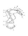
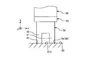
図1に示すロボットシステム100は、ロボット1と、ロボット1の作動を制御する制御装置5と、を備えている。このロボットシステム100は、例えば、腕時計のような精密機器等を製造する製造工程等で用いることができる。
The
〈ロボット〉
図1に示すロボット1は、精密機器やこれを構成する部品(対象物)の給材、除材、搬送および組立等の作業を行うことができる。
<robot>
The
ロボット1は、6軸の垂直多関節ロボットであり、基台11と、基台11に接続されたロボットアーム20と、ロボットアーム20の先端部に設けられた力検出器40とハンド30と、を有する。また、図2に示すように、ロボット1は、ロボットアーム20を駆動させる動力を発生させる複数の駆動源13や複数のモータードライバー12を備えている。
The
図1に示す基台11は、ロボット1を任意の設置箇所に取り付ける部分である。なお、基台11の設置箇所は、特に限定されず、例えば、床、壁、天井、移動可能な台車上などが挙げられる。
The base 11 shown in FIG. 1 is a part for attaching the
ロボットアーム20は、第1アーム21(アーム)と、第2アーム22(アーム)と、第3アーム23(アーム)と、第4アーム24(アーム)と、第5アーム25(アーム)と、第6アーム26(アーム)とを有する。第1アーム21と第2アーム22と第3アーム23と第4アーム24と第5アーム25と第6アーム26とは、基端側から先端側に向ってこの順に連結されている。第1アーム21は、基台11に接続されている。第6アーム26の先端には、例えば、各種部品等を把持するハンド30(エンドエフェクター)が着脱可能に取り付けられている。
The
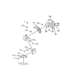
図3に示すように、基台11と第1アーム21とは、関節171(ジョイント)を介して連結されている。第1アーム21は、基台11に対し、鉛直方向と平行な第1回動軸O1を回動中心として回動可能となっている。
As shown in FIG. 3, the
第1アーム21と第2アーム22とは、関節172(ジョイント)を介して連結されている。第2アーム22は、第1アーム21に対し、水平方向と平行な第2回動軸O2を回動中心として回動可能となっている。第2回動軸O2は、第1回動軸O1と直交している。
The
第2アーム22と第3アーム23とは、関節173(ジョイント)を介して連結されている。第3アーム23は、第2アーム22に対し、水平方向と平行な第3回動軸O3を回動中心として回動可能となっている。第3回動軸O3は、第2回動軸O2と平行である。
The
第3アーム23と第4アーム24とは、関節174(ジョイント)を介して連結されている。第4アーム24は、第3アーム23に対し、第3アーム23の中心軸方向と平行な第4回動軸O4を回動中心として回動可能となっている。
The
第4アーム24と第5アーム25とは、関節175(ジョイント)を介して連結されている。第5アーム25は、第4アーム24に対し、第5回動軸O5を回動中心として回動可能となっている。第5回動軸O5は、第4回動軸O4と直交している。
The
第5アーム25と第6アーム26とは、関節176(ジョイント)を介して連結されている。第6アーム26は、第5アーム25に対し、第6回動軸O6を回動中心とて回動可能となっている。第6回動軸O6は、第5回動軸O5と直交している。
The
図2に示すように、各アーム21〜26には、それぞれ、サーボモーター等のモーターおよび減速機を有する複数の駆動源13が設けられている。すなわち、ロボット1は、アーム21〜26に対応した数(本実施形態では6つ)の駆動源13を有している。そして、各アーム21〜26は、それぞれ、対応する駆動源に電気的に接続された複数(本実施形態では6つ)のモータードライバー12を介して制御装置5により制御されている。なお、モータードライバーは、基台11内に収納されている。
As shown in FIG. 2, each of the
また、各駆動源13には、例えば、エンコーダー、ロータリーエンコーダー等の角度センサー(図示せず)が設けられている。これにより、各駆動源13が有するモーターまたは減速機の回転軸の回転角度を検出することができる。
Further, each
図1に示すように、力検出器40は、円形の板状をなし、第6アーム26の先端部に設けられている。この力検出器40は、第6アーム26とハンド30との間に位置している。
As shown in FIG. 1, the
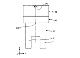
図4に示すように、力検出器40は、互いに直交する3つの軸(x軸、y軸、z軸)方向の並進力成分Fx、Fy、Fzおよび3つの軸(x軸、y軸、z軸)周りの回転力成分(モーメント)Mx、My、Mzの6成分を検出することができる6軸力覚センサーである。3つの軸(x軸、y軸、z軸)は、x軸およびy軸が力検出器40の先端面(基端面)に平行であり、z軸が力検出器40の厚さ方向に平行である。
As shown in FIG. 4, the
このような力検出器40によって、ロボット1は、ハンド30にかかる力やモーメントを検出することができる。
With such a
なお、本実施形態では、力検出器40は、第6アーム26の先端部に設けられているが、力検出器40の設置箇所は、ハンド30にかかる力やモーメントを検出することができる位置であれば如何なる箇所であってもよい。例えば、力検出器40は、第6アーム26の基端部に設けられていてもよい。
In the present embodiment, the
図1および図4に示すように、第6アーム26の先端部(ロボットアーム20の先端部)には、力検出器40を介して、ハンド30(エンドエフェクター)が着脱可能に取り付けられている。このハンド30は、2本の指31、32を有しており、指31、32で例えば各種部品等を把持することができる。
As shown in FIGS. 1 and 4, a hand 30 (end effector) is detachably attached to a distal end portion of the sixth arm 26 (a distal end portion of the robot arm 20) via a
図4に示すように、本実施形態では、ハンド30は、その基端面の中心O30(および、2つの指31、32の間の領域の中心)が、アーム26の第6回動軸O6上に位置するようにロボットアーム20に取り付けられている。
As shown in FIG. 4, in the present embodiment, the
なお、本実施形態では、前述したように、ハンド30は、ロボットアーム20に対して着脱可能に設けられているが、ロボットアーム20に対して固設されていてもよい。また、本実施形態では、ハンド30は、2本の指31、32を有しているが、ハンド30の指の数は、任意であり、例えば、3本や4本等であってもよい。また、本実施形態では、エンドエフェクターとしてハンド30を用いているが、エンドエフェクターとしては、ハンド30以外の構成であってもよく、各種部品等に対する作業(例えば、把持、持ち上げまたは吸着)を行うことができる構成であれば如何なる構成であってもよい。また、エンドエフェクターのロボットアーム20に対する数や配置は、図示のものに限定されない。
In the present embodiment, as described above, the
以上、ロボット1の構成について簡単に説明した。このような構成のロボット1は、前述したように、6つ(複数)のアーム21〜26を有する垂直多関節ロボットであるため、駆動範囲が広く、高い作業性を発揮することができる。
The configuration of the
〈制御装置〉
図1に示す制御装置5は、ロボット1の各部を制御する。この制御装置5は、例えば、CPU(Central Processing Unit)やROM(read only memory)およびRAM(Random Access Memory)が内蔵されたパーソナルコンピューター(PC)等で構成することができる。
<Control device>
The
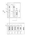
図2に示すように、制御装置5は、駆動制御部51と、情報取得部52と、接触判断部53と、処理部54と、記憶部55と、を備える。
As shown in FIG. 2, the
駆動制御部51は、各アーム21〜26の駆動を担う各駆動源13の駆動を制御する。例えば、駆動制御部51は、力検出器40および角度センサー(図示せず)の検出結果(信号)に基づき、各アーム21〜26をそれぞれ独立して駆動させたり停止させたりすることができる。
The
情報取得部52は、力検出器40で検出された検出結果を取得する。
接触判断部53は、情報取得部52で取得した検出結果(並進力成分Fx、Fy、Fzおよび回転力成分Mx、My、Mz)と、後述する記憶部55に記憶されている情報(ハンド30と作業面60とが接触したときに力検出器40から出力される検出結果)とを基に、ハンド30が作業面60(図5参照)に接触したか否かを判断する。
The
The
処理部54は、情報取得部52で取得した検出結果を基に、ハンド30の教示点や姿勢を求めたりする。
The processing unit 54 obtains the teaching point and posture of the
記憶部55は、制御装置50が各種処理を行うためのプログラムやデータ等を記憶する。また、記憶部55には、例えば、ハンド30が作業面60に接触したときに力検出器40から出力される検出結果等の情報(データベース)が予め記憶されている。
The
なお、このような制御装置5は、本実施形態では、図1に示すように、ロボット1とは、別体で設けられているが、ロボット1に内蔵されていてもよい。
以上、ロボットシステム100の基本的な構成について簡単に説明した。
In the present embodiment, such a
The basic configuration of the
このようなロボットシステム100では、ロボット1が作業面60において各種部品の把持等の作業を行うに際し、ロボット1に、図5に示すような作業面60に対するハンド30の位置や姿勢を教示(ティーチング)する。
In such a
ロボット1の作業では、ハンド30(具体的には、指31の先端面および指32の先端面)を作業面60に対してほぼ平行にすることで、ハンド30による作業性が向上する。作業面60は、例えば、作業台上の面や、ロボット1が組立等を行う部品が有する面である。このロボット1が作業をする作業面60は一定の向きになっているとは限らない。そこで、ロボット1に、図5に示すような作業面60に対するハンド30の位置や姿勢を教示する。
In the operation of the
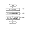
図6に示すように、ロボット1の教示は、教示点の算出(ステップS100)と、作業面の座標系の算出(ステップS200)と、作業面に対するハンドの位置および姿勢の教示(ステップS300)と、を有している。
As shown in FIG. 6, the teaching of the
なお、以下の説明では、図5に示すように、最終的に求める作業面60の座標系が、X軸およびY軸を含むX−Y面に平行で、Z軸を法線とする場合について説明する。
In the following description, as shown in FIG. 5, the case where the coordinate system of the
[教示点の算出(ステップS100)]
まず、教示点の算出(ステップS100)を行う。
図7に示すフローを参照しつつ、教示点の算出(ステップS100)について説明する。この教示点の算出(ステップS100)では、作業面60上の互いに離れた任意の3つの箇所A、B、C(3つの測定点)におけるハンド30の教示点を算出する。
[Calculation of teaching point (step S100)]
First, the teaching point is calculated (step S100).
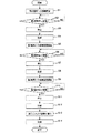
The calculation of the teaching point (step S100) will be described with reference to the flow shown in FIG. In the calculation of the teaching points (step S100), the teaching points of the
まず、箇所Aにおける教示点を求める。
図7に示すように、駆動制御部51の指令によりロボットアーム20を駆動して、ハンド30の箇所A(目的箇所)への接近(移動)を開始する(ステップS1)。ここで、ハンド30を箇所Aへ接近させる際、作業面60に対してハンド30を傾けた状態で接近させる。
First, a teaching point at the location A is obtained.
As shown in FIG. 7, the
上記のようにしてハンド30を箇所Aへ接近させていき、情報取得部52にて取得した力検出器40からの検出結果を基に、接触判断部53にてハンド30が作業面60に接触したか否かを判断する(ステップS2)。接触したと判断されるまでハンド30の箇所Aへの接近を続け、接触したと判断された場合には、駆動制御部51の指令によりロボットアーム20の駆動を停止する(ステップS3)。
The
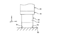
ハンド30が作業面60に接触した場合、例えば、ハンド30は、図8に示すような状態となる。ここで、ハンド30の作業面60に最初に接触した部分を「第1部分3a」とする。本実施形態では、第1部分3aは、指31の先端面のうちの一端とする。また、この1回目の接触では、指32が作業面60に接触していない。
When the
次に、第1部分3aが作業面60に接触したときの力検出器40の検出結果(並進力成分Fx、Fy、Fzおよび回転力成分Mx、My、Mz)を記憶部55にて記憶(記録)する(ステップS4)。
Next, the detection results (translational force components Fx, Fy, Fz and rotational force components Mx, My, Mz) of the
次に、ハンド30の、第1軸周りの姿勢の変更を開始する(ステップS5)。ここでは、第1部分3aを作業面60に接触させた状態のまま、第1部分3aを支点としてハンド30を第1軸(図示の場合、y軸)周りに、かつ、ハンド30の先端部が作業面60に接触する方向に回動させる。
Next, the posture of the
上記のようにしてハンド30を回動させていき、情報取得部52にて取得した力検出器40からの検出結果を基に接触判断部53にてハンド30の第1部分3aとは異なる第2部分3bが作業面60に接触したか否かを判断する(ステップS6)。第2部分3bが接触したと判断されるまでハンド30を第1軸周りに回動させ、第2部分3bが接触したと判断された場合には、駆動制御部51の指令によりロボットアーム20の駆動を停止する
(ステップS7)。
The
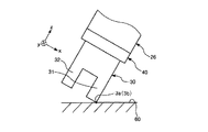
第2部分3bが接触すると、ハンド30は、例えば、図9および図10に示すような状態となる。本実施形態では、第2部分3bは、指31の先端面のうちの第1部分3aとは反対側の端とする。また、図10に示すように、2回目の接触では、指32が作業面60に接触していない。
When the
次に、第1部分3aおよび第2部分3bが作業面60に接触したときの力検出器40の検出結果(並進力成分Fx、Fy、Fzおよび回転力成分Mx、My、Mz)を記憶部55にて記憶(記録)する(ステップS8)。
Next, the storage unit stores the detection results (translational force components Fx, Fy, Fz and rotational force components Mx, My, Mz) of the
次に、ハンド30の、第2軸周りの姿勢の変更を開始する(ステップS9)。ここでは、第1部分3aおよび第2部分3bを作業面60に接触させた状態のまま、第1部分3aおよび第2部分3bを通る線分(仮想線)を支軸としてハンド30を第2軸(図示の場合、y軸)周りに、かつ、ハンド30の先端部が作業面60に接触する方向に回動させる。
Next, the posture of the
上記のようにしてハンド30を回動させていき、情報取得部52にて取得した力検出器40からの検出結果を基に接触判断部53にてハンド30の第1部分3aおよび第2部分3bとは異なる第3部分3cが作業面60に接触したか否かを判断する(ステップS10)。第3部分3cが接触したと判断されるまでハンド30を第2軸周りに回動させ、第3部分3cが接触したと判断された場合には、駆動制御部51の指令によりロボットアーム20の駆動を停止する(ステップS11)。
The
第3部分3cが接触すると、例えば、ハンド30は、図11に示すような状態となる。本実施形態では、第3部分3cは、指32の先端面とする。この3回目のハンド30の接触で、ハンド30の先端面(指31および指32の各先端面)全体が作業面60に接触する。
When the
次に、第1部分3a、第2部分3bおよび第3部分3cが作業面60に接触したときの力検出器40の検出結果(並進力成分Fx、Fy、Fzおよび回転力成分Mx、My、Mz)を記憶部55にて記憶(記録)する(ステップS12)。
Next, the detection results of the
次に、ステップS4、S8、S12にて記憶(記録)した力検出器40の検出結果(並進力成分Fx、Fy、Fzおよび回転力成分Mx、My、Mz)を基に、処理部54にて、教示点X10の位置と、作業面60に対するハンド30の姿勢とを求める(ステップS13)。なお、本実施形態では、ハンド30の先端部の中心(具体的には、2つの指31、32の間の領域の中心)を教示点X10として求める。
Next, based on the detection results (translational force components Fx, Fy, Fz and rotational force components Mx, My, Mz) of the
そして、求めた教示点X10の位置と、作業面60に対するハンド30の姿勢とを記憶部55に記憶(記録)する(ステップS14)。
Then, the obtained position of the teaching point X10 and the posture of the
以上のようにして、箇所Aにおける教示点X10および作業面60に対するハンド30の姿勢が算出される。このように、複数の部分(第1部分3a、第2部分3bおよび第3部分3c)から教示点X10および作業面60に対するハンド30の姿勢を求めているため、教示点X10の位置の精度および作業面60に対するハンド30の姿勢の精度をより高めることができる。
As described above, the posture of the
また、同様にして、箇所Bおよび箇所Cにおける各教示点X10および作業面60に対するハンド30の姿勢についても求める。これにより、3つの箇所(箇所A、B、C)における教示点X10および作業面60に対するハンド30の姿勢が算出される。
Similarly, the posture of the
[作業面の座標系の算出(ステップS200)]
次に、図6に示すように、作業面の座標系の算出(ステップS200)を行う。
[Calculation of coordinate system of work surface (step S200)]
Next, as shown in FIG. 6, the coordinate system of the work surface is calculated (step S200).
作業面の座標系の算出(ステップS200)では、処理部54にて、3の箇所A、B、Cにおける各教示点X10を基にして作業面60の座標系を求める。3の箇所A、B、Cで、それぞれ、前述したように、複数の部分から教示点X10を算出しているため、作業面60の座標系をより高精度に求めることができる。
In the calculation of the coordinate system of the work surface (step S200), the processing unit 54 obtains the coordinate system of the
また、作業面の座標系の算出(ステップS200)では、処理部54にて、3の箇所A、B、Cにおけるハンド30の姿勢から、作業面60が平面であるか否かを判断する。例えば、3つの箇所A、B、CにおけるX軸周りに回転力成分MxとY軸周りの回転力成分Myとが、所定の差以内であれば作業面60が平面であると判断する。すなわち、3つの箇所A、B、Cにおける各回転力成分Mx、Myが、ほぼ同等であれば、作業面60が平面であると判断する。一方、3つの箇所A、B、Cにおける各回転力成分Mx、Myが、所定の範囲外である場合、作業面60は平面でなく、曲面であったり、凹凸等があったりすると判断する。これにより、作業面60の状態をより正確に把握することができる。
In the calculation of the coordinate system of the work surface (step S200), the processing unit 54 determines whether or not the
[作業面に対するハンドの位置の教示(ステップS300)]
次に、図6に示すように、作業面に対するハンドの位置の教示(ステップS300)に行う。
[Teaching of Hand Position with respect to Work Surface (Step S300)]
Next, as shown in FIG. 6, the teaching of the position of the hand with respect to the work surface is performed (step S300).
作業面に対するハンドの位置の教示(ステップS300)では、作業面60の座標系を基にロボット1に作業面60に対するハンド30の位置および姿勢を教示する。
In the teaching of the position of the hand with respect to the work surface (step S300), the
以上のような作業面の教示(ステップS300)を経て、ロボット1の教示は終了する(図6参照)。
以上、ロボット1の教示について説明した。
After the teaching of the work surface as described above (step S300), the teaching of the
The teaching of the
以上説明したように、ロボットシステム100では、制御装置5が、力検出器40を備えたロボット1を制御しているため、作業面60に対するハンド30の位置をより高精度に教示させることができる。このため、ティーチングペンダントのような教示専用のツールを用いることを省くことができ、ユーザー(作業者)による作業面60とハンド30との接触の判断を省くことができる。
As described above, in the
また、本実施形態では、前述したように、ロボット1の教示において、ハンド30の第1部分3aを作業面60に接触させた後、第1部分3aを作業面60に接触させたまま、第1部分3aとは異なる第2部分3bを作業面60に接触させている。その後、第1部分3aおよび第2部分3bを作業面60に接触させたまま、第1部分3aおよび第2部分3bとは異なる第3部分3cを作業面60に接触させている。このように、本実施形態では、ロボット1の教示において、第1部分3a、第2部分3bおよび第3部分3cと、この順にハンド30を作業面60に接触させていく、いわゆる倣い動作を行っている。そのため、第1部分3a、第2部分3bおよび第3部分3cをより確実に接触させることができるので、ロボット1に、作業面60に対するハンド30の位置および姿勢を高精度に教示することができる。
In the present embodiment, as described above, in the teaching of the
特に、第2部分3bを接触させる際、第1部分3aを支点としてハンド30を第1軸周りに、すなわち、1つの軸回りに回動させている。同様に、第3部分3cを接触させる際、第1部分3aおよび第2部分3bを通る仮想線を支軸としてハンド30を第2軸周りに、すなわち、前述した第1軸とは異なる1つの軸回りに回動させている。このように、本実施形態では、ハンド30の異なる部分(第1部分3a、第2部分3bおよび第3部分3c)を順に接触させていくので、各部分をより確実に接触させることができ、よって、ハンド30の先端面全体を作業面60により容易にかつより確実に接触させることができる。そのため、作業面60の座標系およびハンド30の姿勢をより高精度に求めることができ、その結果、ロボット1に、作業面60に対するハンド30の位置および姿勢をより高精度に教示することができる。
In particular, when the
また、前述したように、ハンド30を箇所Aに最初に接近させる際、作業面60に対してハンド30を傾けた状態で接近させている。すなわち、作業面60に対してハンド30を1回目に接触させる際に、作業面60のX、Y、Z軸に対して交差する方向にハンド30を傾けた状態で接近させている。これにより、作業面60に対してハンド30を1回目に接触させる際に、作業面60に対してハンド30の第1部分3aのみを接触させることができる。そのため、その後、第2部分3bと第3部分3cとをこの順に接触させ易くなり、よって、ハンド30の先端面全体をより容易かつより確実に作業面60に接触させることができる。
Further, as described above, when the
また、本実施形態では、前述したように、教示されるロボット1が、垂直多関節ロボットである。このような構成のロボット1が作業を行う作業面60は、一定な箇所であるとは限らないことが多い。そのため、垂直多関節ロボットであるロボット1に対して、前述したような教示を行うことで、ロボット1の作業性をより高めることができる。
In the present embodiment, as described above, the
なお、前述したように、ロボット1の教示において、求めた教示点の数は3つであるが、教示点の数は、ロボット1が垂直多関節ロボットである場合には、少なくとも3つ以上であればよく、その数は限定されず任意である。
Note that, as described above, in the teaching of the
また、本実施形態では、ロボット1が垂直多関節ロボットである場合を例に説明したが、水平多関節ロボットである場合には、第3部分3cの接触を省略してもよい。また、水平多関節ロボットである場合には、箇所Cの接触を省略してもよい。すなわち、少なくとも2つの接触部分から1つの教示点を求め、そして、少なくとも2つ教示点を算出すればよい。
In the present embodiment, the case where the
なお、水平多関節ロボットとしては、例えば、基台と、基台に接続され、水平方向に延びている第1アーム(第nアーム)と、第1アームに接続され、水平方向に延びる部分を有する第2アーム(第(n+1)アーム)とを有する構成が挙げられる。 As the horizontal articulated robot, for example, a base, a first arm (n-th arm) connected to the base and extending in the horizontal direction, and a portion connected to the first arm and extending in the horizontal direction are included. And a second arm ((n + 1) th arm).
また、前述したロボット1の教示では、ステップS200にて、作業面60の座標系を算出したが、予め設定されている基準面(仮想面)の座標系に対する作業面60全体の座標を求めてもよい。
In the teaching of the
以上、本発明の制御装置、ロボットおよびロボットシステムを、図示の実施形態に基づいて説明したが、本発明はこれに限定されるものではなく、各部の構成は、同様の機能を有する任意の構成のものに置換することができる。また、他の任意の構成物が付加されていてもよい。また、本発明は、前記各実施形態のうちの、任意の2以上の構成(特徴)を組み合わせたものであってもよい。 As described above, the control device, the robot, and the robot system of the present invention have been described based on the illustrated embodiment. However, the present invention is not limited to this, and the configuration of each unit may be any configuration having the same function. Can be replaced by Further, other arbitrary components may be added. Further, the present invention may be a combination of any two or more configurations (features) of the above embodiments.
また、前記実施形態では、ロボットが有するロボットアームの回動軸の数は、6つであるが、本発明では、これに限定されず、ロボットアームの回動軸の数は、例えば、2つ、3つ、4つ、5つまたは7つ以上でもよい。また、前記実施形態では、ロボットが有するアームの数は、6つであるが、本発明では、これに限定されず、ロボットが有するアームの数は、例えば、2つ、3つ、4つ、5つ、または、7つ以上でもよい。 Further, in the above embodiment, the number of rotation axes of the robot arm of the robot is six, but the present invention is not limited to this, and the number of rotation axes of the robot arm is, for example, two. There may be three, four, five or seven or more. In the above embodiment, the number of arms of the robot is six, but the present invention is not limited to this, and the number of arms of the robot is, for example, two, three, four, There may be five or seven or more.
また、前記実施形態では、ロボットが有するロボットアームの数は、1つであるが、本発明では、これに限定されず、ロボットが有するロボットアームの数は、例えば、2つ以上でもよい。すなわち、ロボットは、例えば、双腕ロボット等の複数腕ロボットであってもよい。 In the above-described embodiment, the number of robot arms included in the robot is one. However, the present invention is not limited to this. For example, the number of robot arms included in the robot may be two or more. That is, the robot may be, for example, a multi-arm robot such as a dual-arm robot.
100…ロボットシステム、1…ロボット、3a…第1部分、3b…第2部分、3c…第3部分、5…制御装置、11…基台、12…モータードライバー、13…駆動源、20…ロボットアーム、21…第1アーム、22…第2アーム、23…第3アーム、24…第4アーム、25…第5アーム、26…第6アーム、30…ハンド、31…指、32…指、40…力検出器、50…制御装置、51…駆動制御部、52…情報取得部、53…接触判断部、54…処理部、55…記憶部、60…作業面、171…関節、172…関節、173…関節、174…関節、175…関節、176…関節、A…箇所、B…箇所、C…箇所、O1…第1回動軸、O2…第2回動軸、O3…第3回動軸、O4…第4回動軸、O5…第5回動軸、O6…第6回動軸、O30…中心、S100…ステップ、S200…ステップ、S300…ステップ、S1…ステップ、S2…ステップ、S3…ステップ、S4…ステップ、S5…ステップ、S6…ステップ、S7…ステップ、S8…ステップ、S9…ステップ、S10…ステップ、S11…ステップ、S12…ステップ、S13…ステップ、S14…ステップ、X10…教示点
Claims (10)
前記エンドエフェクターの第1部分を作業面に接近させて、前記力検出器からの出力に基づいて前記第1部分と前記作業面との接触を検出した後、前記第1部分とは異なる前記エンドエフェクターの第2部分を前記作業面に接近させて、前記力検出器からの出力に基づいて前記第2部分と前記作業面との接触を検出し、前記作業面に対する前記エンドエフェクターの位置を前記ロボットに教示させ、
前記第2部分を前記作業面に接触させた後、前記第1部分および前記第2部分とは異なる前記エンドエフェクターの第3部分を前記作業面に接近させて、前記力検出器からの出力に基づいて前記第3部分と前記作業面との接触を検出することを特徴とする制御装置。 An arm, an end effector provided on the arm, and a force detector provided on the arm and detecting a force, a control device for controlling a robot having:
A first portion of the end effector is brought closer to a work surface, and after detecting contact between the first portion and the work surface based on an output from the force detector, the end portion different from the first portion is detected. A second part of the effector is brought closer to the work surface, and a contact between the second part and the work surface is detected based on an output from the force detector, and a position of the end effector with respect to the work surface is determined. Let the robot teach ,
After bringing the second portion into contact with the work surface, the third portion of the end effector different from the first portion and the second portion is brought closer to the work surface, and the output from the force detector is output. A control device for detecting a contact between the third portion and the work surface based on the control information.
前記制御装置により制御されるロボットと、を備えることを特徴とするロボットシステム。 A control device according to any one of claims 1 to 8 , and
A robot controlled by the control device.
Priority Applications (3)
| Application Number | Priority Date | Filing Date | Title |
|---|---|---|---|
| JP2015175430A JP6661925B2 (en) | 2015-09-07 | 2015-09-07 | Control devices, robots and robot systems |
| US15/256,979 US10195744B2 (en) | 2015-09-07 | 2016-09-06 | Control device, robot, and robot system |
| CN201610808829.3A CN106493711B (en) | 2015-09-07 | 2016-09-07 | Controls, Robots, and Robotic Systems |
Applications Claiming Priority (1)
| Application Number | Priority Date | Filing Date | Title |
|---|---|---|---|
| JP2015175430A JP6661925B2 (en) | 2015-09-07 | 2015-09-07 | Control devices, robots and robot systems |
Publications (2)
| Publication Number | Publication Date |
|---|---|
| JP2017052015A JP2017052015A (en) | 2017-03-16 |
| JP6661925B2 true JP6661925B2 (en) | 2020-03-11 |
Family
ID=58190031
Family Applications (1)
| Application Number | Title | Priority Date | Filing Date |
|---|---|---|---|
| JP2015175430A Active JP6661925B2 (en) | 2015-09-07 | 2015-09-07 | Control devices, robots and robot systems |
Country Status (3)
| Country | Link |
|---|---|
| US (1) | US10195744B2 (en) |
| JP (1) | JP6661925B2 (en) |
| CN (1) | CN106493711B (en) |
Families Citing this family (10)
| Publication number | Priority date | Publication date | Assignee | Title |
|---|---|---|---|---|
| JP6710946B2 (en) * | 2015-12-01 | 2020-06-17 | セイコーエプソン株式会社 | Controllers, robots and robot systems |
| CN108858182B (en) * | 2017-05-08 | 2023-01-10 | 精工爱普生株式会社 | Robot control device, robot control method, and robot system |
| JP2019027920A (en) * | 2017-07-31 | 2019-02-21 | セイコーエプソン株式会社 | Force detection device and robot |
| CN107584493B (en) * | 2017-08-29 | 2020-08-14 | 成都乐创自动化技术股份有限公司 | Method and system for capturing target teaching points |
| JP2019051578A (en) * | 2017-09-19 | 2019-04-04 | セイコーエプソン株式会社 | Robot, robot system, and robot controller |
| JP7052308B2 (en) * | 2017-11-15 | 2022-04-12 | セイコーエプソン株式会社 | Sensors and robots |
| JP2021062436A (en) * | 2019-10-11 | 2021-04-22 | セイコーエプソン株式会社 | Teaching method |
| JP2021062443A (en) * | 2019-10-11 | 2021-04-22 | セイコーエプソン株式会社 | Teaching method |
| JP7620391B2 (en) * | 2020-03-18 | 2025-01-23 | 株式会社東芝 | CONTROL DEVICE, INSPECTION SYSTEM, CONTROL METHOD, PROGRAM, AND STORAGE MEDIUM |
| JP7619070B2 (en) * | 2021-02-10 | 2025-01-22 | セイコーエプソン株式会社 | Teaching device, teaching method, and teaching program |
Family Cites Families (19)
| Publication number | Priority date | Publication date | Assignee | Title |
|---|---|---|---|---|
| JP2787891B2 (en) * | 1993-09-08 | 1998-08-20 | 三菱電機株式会社 | Automatic teaching device for laser robot |
| JP3671694B2 (en) | 1998-09-18 | 2005-07-13 | 株式会社デンソー | Robot teaching method and apparatus |
| JP4264778B2 (en) * | 1999-07-26 | 2009-05-20 | 東芝機械株式会社 | Working robot and teaching point position / posture data measuring method |
| JP2001038660A (en) * | 1999-07-26 | 2001-02-13 | Toshiba Mach Co Ltd | Teaching end effector, and robot teaching method |
| JP4056080B2 (en) * | 2006-01-13 | 2008-03-05 | 松下電器産業株式会社 | Robot arm control device |
| JP5013270B2 (en) * | 2006-02-02 | 2012-08-29 | 株式会社安川電機 | Robot system |
| JP2010023184A (en) * | 2008-07-18 | 2010-02-04 | Fanuc Ltd | Setting method for working coordinate system, and abnormality detection device for working coordinate system |
| JP4598849B2 (en) * | 2008-09-03 | 2010-12-15 | ファナック株式会社 | Fitting device for correcting clogged fitting |
| JP4568795B2 (en) * | 2009-01-09 | 2010-10-27 | パナソニック株式会社 | Robot arm control device and control method, robot, robot arm control program, and integrated electronic circuit |
| JP5459486B2 (en) * | 2010-01-26 | 2014-04-02 | 株式会社Ihi | Robot calibration method and apparatus |
| CN103038028B (en) * | 2011-01-27 | 2015-05-27 | 松下电器产业株式会社 | Robot-arm control device and control method, robot, and integrated electronic circuit |
| JP5915214B2 (en) * | 2012-02-01 | 2016-05-11 | セイコーエプソン株式会社 | Robot apparatus, assembling method, and assembling program |
| JP5695223B2 (en) * | 2012-05-23 | 2015-04-01 | パナソニックIpマネジメント株式会社 | ROBOT, ROBOT CONTROL DEVICE, CONTROL METHOD, AND CONTROL PROGRAM |
| WO2014129524A1 (en) * | 2013-02-20 | 2014-08-28 | 株式会社Ihi | Force control robot and method for controlling same |
| JP2014176940A (en) * | 2013-03-15 | 2014-09-25 | Yaskawa Electric Corp | Robot system, method for controlling robot and method for manufacturing workpiece |
| JP6468741B2 (en) * | 2013-07-22 | 2019-02-13 | キヤノン株式会社 | Robot system and robot system calibration method |
| CN104608128A (en) * | 2013-11-01 | 2015-05-13 | 精工爱普生株式会社 | Robot, control device, robot system and robot control method |
| JP2015226968A (en) * | 2014-06-02 | 2015-12-17 | セイコーエプソン株式会社 | Robot, robot system, control unit and control method |
| CN105313127A (en) * | 2014-06-02 | 2016-02-10 | 精工爱普生株式会社 | Robot, control method of robot, and control device of robot |
-
2015
- 2015-09-07 JP JP2015175430A patent/JP6661925B2/en active Active
-
2016
- 2016-09-06 US US15/256,979 patent/US10195744B2/en active Active
- 2016-09-07 CN CN201610808829.3A patent/CN106493711B/en active Active
Also Published As
| Publication number | Publication date |
|---|---|
| US10195744B2 (en) | 2019-02-05 |
| CN106493711B (en) | 2021-04-16 |
| JP2017052015A (en) | 2017-03-16 |
| US20170066137A1 (en) | 2017-03-09 |
| CN106493711A (en) | 2017-03-15 |
Similar Documents
| Publication | Publication Date | Title |
|---|---|---|
| JP6661925B2 (en) | Control devices, robots and robot systems | |
| JP6733239B2 (en) | Controller and robot system | |
| JP6511715B2 (en) | Robot control device, robot system, and robot | |
| US10434646B2 (en) | Robot control apparatus, robot, and robot system | |
| JP6746990B2 (en) | Robot controller and robot system | |
| JP6663978B2 (en) | System and method for determining tool offset | |
| US10960542B2 (en) | Control device and robot system | |
| JP2015182142A (en) | Robot, robot system, and teaching method | |
| JP2018118365A (en) | Control device and robot system | |
| US10537988B2 (en) | Controller, robot and robot system | |
| JP7187765B2 (en) | robot controller | |
| CN108068110A (en) | control device, robot and robot system | |
| JP2017205819A (en) | Robot, control device and robot system | |
| JP2014155994A (en) | Robot and robot control device | |
| JPWO2017175340A1 (en) | Optimization device and vertical articulated robot having the same | |
| JP2015085499A (en) | Robot, robot system, control apparatus and control method | |
| JP2019063879A (en) | Simulation device, robot control device and robot | |
| JP2020157475A (en) | Control device, robot system, and robot control method | |
| JP2015089578A (en) | Robot system | |
| CN112643683B (en) | Teaching method | |
| WO2025028401A1 (en) | Robot system | |
| JP2020040185A (en) | Robot arm, robot device using robot arm, control method of robot arm, control program, and recording medium | |
| JP2019141976A (en) | Control device, control method of robot, and robot system | |
| KR20170133143A (en) | Apparatus and Method for Controlling Robot Arms |
Legal Events
| Date | Code | Title | Description |
|---|---|---|---|
| A621 | Written request for application examination |
Free format text: JAPANESE INTERMEDIATE CODE: A621 Effective date: 20180725 |
|
| RD05 | Notification of revocation of power of attorney |
Free format text: JAPANESE INTERMEDIATE CODE: A7425 Effective date: 20180905 |
|
| RD03 | Notification of appointment of power of attorney |
Free format text: JAPANESE INTERMEDIATE CODE: A7423 Effective date: 20181115 |
|
| A977 | Report on retrieval |
Free format text: JAPANESE INTERMEDIATE CODE: A971007 Effective date: 20190726 |
|
| A131 | Notification of reasons for refusal |
Free format text: JAPANESE INTERMEDIATE CODE: A131 Effective date: 20190806 |
|
| A521 | Written amendment |
Free format text: JAPANESE INTERMEDIATE CODE: A523 Effective date: 20190930 |
|
| TRDD | Decision of grant or rejection written | ||
| A01 | Written decision to grant a patent or to grant a registration (utility model) |
Free format text: JAPANESE INTERMEDIATE CODE: A01 Effective date: 20200114 |
|
| A61 | First payment of annual fees (during grant procedure) |
Free format text: JAPANESE INTERMEDIATE CODE: A61 Effective date: 20200127 |
|
| R150 | Certificate of patent or registration of utility model |
Ref document number: 6661925 Country of ref document: JP Free format text: JAPANESE INTERMEDIATE CODE: R150 |