JP6733239B2 - Controller and robot system - Google Patents
Controller and robot system Download PDFInfo
- Publication number
- JP6733239B2 JP6733239B2 JP2016054959A JP2016054959A JP6733239B2 JP 6733239 B2 JP6733239 B2 JP 6733239B2 JP 2016054959 A JP2016054959 A JP 2016054959A JP 2016054959 A JP2016054959 A JP 2016054959A JP 6733239 B2 JP6733239 B2 JP 6733239B2
- Authority
- JP
- Japan
- Prior art keywords
- robot
- hand
- control device
- predetermined
- control point
- Prior art date
- Legal status (The legal status is an assumption and is not a legal conclusion. Google has not performed a legal analysis and makes no representation as to the accuracy of the status listed.)
- Active
Links
Images


Classifications
-
- B—PERFORMING OPERATIONS; TRANSPORTING
- B25—HAND TOOLS; PORTABLE POWER-DRIVEN TOOLS; MANIPULATORS
- B25J—MANIPULATORS; CHAMBERS PROVIDED WITH MANIPULATION DEVICES
- B25J9/00—Programme-controlled manipulators
- B25J9/0081—Programme-controlled manipulators with master teach-in means
-
- B—PERFORMING OPERATIONS; TRANSPORTING
- B25—HAND TOOLS; PORTABLE POWER-DRIVEN TOOLS; MANIPULATORS
- B25J—MANIPULATORS; CHAMBERS PROVIDED WITH MANIPULATION DEVICES
- B25J13/00—Controls for manipulators
- B25J13/08—Controls for manipulators by means of sensing devices, e.g. viewing or touching devices
- B25J13/085—Force or torque sensors
-
- B—PERFORMING OPERATIONS; TRANSPORTING
- B25—HAND TOOLS; PORTABLE POWER-DRIVEN TOOLS; MANIPULATORS
- B25J—MANIPULATORS; CHAMBERS PROVIDED WITH MANIPULATION DEVICES
- B25J15/00—Gripping heads and other end effectors
- B25J15/08—Gripping heads and other end effectors having finger members
-
- B—PERFORMING OPERATIONS; TRANSPORTING
- B25—HAND TOOLS; PORTABLE POWER-DRIVEN TOOLS; MANIPULATORS
- B25J—MANIPULATORS; CHAMBERS PROVIDED WITH MANIPULATION DEVICES
- B25J9/00—Programme-controlled manipulators
- B25J9/16—Programme controls
- B25J9/1602—Programme controls characterised by the control system, structure, architecture
-
- B—PERFORMING OPERATIONS; TRANSPORTING
- B25—HAND TOOLS; PORTABLE POWER-DRIVEN TOOLS; MANIPULATORS
- B25J—MANIPULATORS; CHAMBERS PROVIDED WITH MANIPULATION DEVICES
- B25J9/00—Programme-controlled manipulators
- B25J9/16—Programme controls
- B25J9/1628—Programme controls characterised by the control loop
- B25J9/1633—Programme controls characterised by the control loop compliant, force, torque control, e.g. combined with position control
-
- B—PERFORMING OPERATIONS; TRANSPORTING
- B25—HAND TOOLS; PORTABLE POWER-DRIVEN TOOLS; MANIPULATORS
- B25J—MANIPULATORS; CHAMBERS PROVIDED WITH MANIPULATION DEVICES
- B25J9/00—Programme-controlled manipulators
- B25J9/16—Programme controls
- B25J9/1679—Programme controls characterised by the tasks executed
-
- G—PHYSICS
- G05—CONTROLLING; REGULATING
- G05B—CONTROL OR REGULATING SYSTEMS IN GENERAL; FUNCTIONAL ELEMENTS OF SUCH SYSTEMS; MONITORING OR TESTING ARRANGEMENTS FOR SUCH SYSTEMS OR ELEMENTS
- G05B19/00—Programme-control systems
- G05B19/02—Programme-control systems electric
- G05B19/42—Recording and playback systems, i.e. in which the programme is recorded from a cycle of operations, e.g. the cycle of operations being manually controlled, after which this record is played back on the same machine
- G05B19/423—Teaching successive positions by walk-through, i.e. the tool head or end effector being grasped and guided directly, with or without servo-assistance, to follow a path
Landscapes
- Engineering & Computer Science (AREA)
- Robotics (AREA)
- Mechanical Engineering (AREA)
- Automation & Control Theory (AREA)
- Human Computer Interaction (AREA)
- Physics & Mathematics (AREA)
- General Physics & Mathematics (AREA)
- Manipulator (AREA)
Description
この発明は、制御装置及びロボットシステムに関する。
This invention relates to a control instrumentation 置及 beauty robotic system.
ロボットが備える力センサーにより検出される力及びモーメントに基づいて、ロボットに動作を教示する技術の研究や開発が行われている。 2. Description of the Related Art Research and development of techniques for teaching motions to robots based on forces and moments detected by force sensors included in the robots have been conducted.
これに関し、教示作業者がロボットのアームの先部に設けられた手先効果器に力を加え、この加えられた力をリスト部に備えた力センサーで検出し、力センサーが出力する力信号に基づく力制御によって手先効果器を目標とする位置に誘導し、誘導した後の手先効果器の位置及び姿勢を教示データとして記憶する直接教示装置が知られている(特許文献1参照)。 In this regard, the teaching operator applies a force to the hand effector provided at the tip of the robot arm, detects the applied force with the force sensor provided in the wrist unit, and outputs the force signal output by the force sensor. There is known a direct teaching device that guides a hand effector to a target position by force control based on the force control and stores the position and posture of the hand effector after the guidance as teaching data (see Patent Document 1).
しかしながら、このような直接教示装置では、予め入力されるパラメーターであって力制御による手先効果器の移動量を算出するために用いられる力制御パラメーターを正確に設定しなければ、手先効果器の位置及び姿勢を、正確に所望の位置及び姿勢に変化させることが困難な場合があった。また、当該直接教示装置では、当該力制御パラメーターを正確に設定することができたとしても、教示作業者が手先効果器に対して所望の方向に所望の力を正確に加えることが困難な場合があり、手先効果器の位置及び姿勢を、正確に所望の位置及び姿勢に変化させることが困難な場合があった。その結果、当該直接教示装置では、所望する位置及び姿勢を、ロボットに正確に教示することができない場合があった。 However, in such a direct teaching device, if the force control parameter that is a parameter that is input in advance and that is used for calculating the movement amount of the hand effector by force control is not accurately set, the position of the hand effector is not changed. In some cases, it is difficult to accurately change the position and the posture to the desired position and posture. Further, in the direct teaching device, when it is difficult for the teaching operator to accurately apply a desired force to a hand effector in a desired direction even if the force control parameter can be set accurately. Therefore, it may be difficult to accurately change the position and orientation of the hand effector to a desired position and orientation. As a result, the direct teaching device may not be able to accurately teach the desired position and orientation to the robot.
上記課題の少なくとも一つを解決するために本発明の一態様は、ハンドと力検出部を備えるロボットの位置及び姿勢を記憶する際、前記ハンドに加わる外力が所定条件を満たすまで前記ロボットを動かす第1モードと、前記ロボットが備える第1部位に加えられた外力に基づき前記ロボットを動かす第2モードとを切り替える、制御装置である。
この構成により、制御装置は、ロボットの位置及び姿勢を記憶する際、ハンドに加わる外力が所定条件を満たすまでロボットを動かす第1モードと、ロボットが備える第1部位に加えられた外力に基づきロボットを動かす第2モードとを切り替える。これにより、制御装置は、第1モードと第2モードとのいずれかによって、ロボットの位置及び姿勢を高い精度で所望の位置及び姿勢へと変化させることができる。
In order to solve at least one of the above problems, according to one aspect of the present invention, when storing the position and orientation of a robot including a hand and a force detection unit, the robot is moved until an external force applied to the hand satisfies a predetermined condition. The control device switches between a first mode and a second mode in which the robot is moved based on an external force applied to a first part of the robot.
With this configuration, when the control device stores the position and orientation of the robot, the controller moves the robot until the external force applied to the hand satisfies a predetermined condition, and the robot based on the external force applied to the first part of the robot. Switch to the second mode of moving. Thereby, the control device can change the position and orientation of the robot to a desired position and orientation with high accuracy by using either the first mode or the second mode.
また、本発明の他の態様は、制御装置において、前記第1モードにおいて、前記所定条件が満たされるまで、前記力検出部の出力に基づく制御によって前記ハンドを対象物に近づける、構成が用いられてもよい。
この構成により、制御装置は、第1モードにおいて、所定条件が満たされるまで、力検出部の出力に基づく制御によってハンドを対象物に近づける。これにより、制御装置は、第1モードにおいて、ユーザーによりハンドに外力を加えさせることなく、ロボットの位置及び姿勢を、対象物に対応付けられた所望の位置及び姿勢へと高い精度で変化させることができる。
In another aspect of the present invention, in the control device, in the first mode, a configuration is used in which the hand is brought closer to an object by control based on the output of the force detection unit until the predetermined condition is satisfied. May be.
With this configuration, in the first mode, the control device brings the hand closer to the target object by the control based on the output of the force detection unit until the predetermined condition is satisfied. Accordingly, the control device can change the position and orientation of the robot to the desired position and orientation associated with the object with high accuracy in the first mode without causing the user to apply an external force to the hand. You can
また、本発明の他の態様は、制御装置において、前記所定条件は、前記ハンドに加わる外力のうちの少なくとも第1方向に向かう外力が0より大きくなり、且つ、前記ハンドに加わる外力のうちの少なくとも前記第1方向と異なる第2方向に向かう外力が0となることである、構成が用いられてもよい。
この構成により、制御装置は、第1モードにおいて、ハンドに加わる外力のうちの少なくとも第1方向に向かう外力が0より大きくなり、且つ、ハンドに加わる外力のうちの少なくとも第2方向に向かう外力が0となるまでロボットを動かす。これにより、制御装置は、第1モードにおいて、ロボットの姿勢を保持したまま、第1方向と反対の方向に向かってロボットの位置を移動させることができる。
In another aspect of the present invention, in the control device, the predetermined condition is that at least the external force applied to the hand in the first direction is greater than 0 and the external force applied to the hand is A configuration may be used in which the external force toward at least the second direction different from the first direction is zero.
With this configuration, in the control device, in the first mode, at least the external force applied to the hand in the first direction is greater than 0, and the external force applied to the hand in at least the second direction is greater than 0. Move the robot until it reaches 0. Accordingly, the control device can move the position of the robot in the direction opposite to the first direction while maintaining the posture of the robot in the first mode.
また、本発明の他の態様は、制御装置において、前記第1方向は、並進方向であり、前記第2方向は、回転方向である、構成が用いられてもよい。
この構成により、制御装置は、第1モードにおいて、ハンドに加わる力のうちの少なくとも並進方向である第1方向に向かう力が0より大きくなり、且つ、回転方向である第2方向に向かうモーメントが0となるまでロボットを動かす。これにより、制御装置は、第1モードにおいて、ロボットの姿勢を保持したまま、並進方向である第1方向と反対の方向に向かってロボットの位置を移動させることができる。
Further, according to another aspect of the present invention, in the control device, a configuration may be used in which the first direction is a translational direction and the second direction is a rotational direction.
With this configuration, in the control device, in the first mode, at least the force applied to the hand in the first direction, which is the translational direction, is greater than 0, and the moment directed in the second direction, which is the rotational direction, is increased. Move the robot until it reaches 0. Accordingly, the control device can move the position of the robot in the direction opposite to the first direction, which is the translation direction, while maintaining the posture of the robot in the first mode.
また、本発明の他の態様は、制御装置において、前記第1モードにおいて、前記所定条件が満たされた場合、現在の前記位置及び姿勢を記憶する、構成が用いられてもよい。
この構成により、制御装置は、第1モードにおいて、所定条件が満たされた場合、現在のロボットの位置及び姿勢を記憶する。これにより、制御装置は、第1モードにおいて、所定条件を満たされた場合に記憶されたロボットの位置及び姿勢に基づいてロボットを動作させることができる。
Further, as another aspect of the present invention, in the control device, in the first mode, when the predetermined condition is satisfied, the present position and orientation may be stored.
With this configuration, the control device stores the current position and orientation of the robot when the predetermined condition is satisfied in the first mode. Accordingly, the control device can operate the robot based on the stored position and orientation of the robot when the predetermined condition is satisfied in the first mode.
また、本発明の他の態様は、制御装置において、前記第2モードにおいて、前記第1部位に加えられた外力に基づいて、前記ロボットが備える第2部位を所定方向に所定量だけ移動させる、構成が用いられてもよい。
この構成により、制御装置は、第2モードにおいて、ロボットが備える第1部位に加えられた外力に基づいて、ロボットが備える第2部位を所定方向に所定量だけ移動させる。これにより、制御装置は、第2モードにおいて、ユーザーにより第1部位に加えられる外力に基づいて、ロボットの位置及び姿勢を高い精度で所望の位置及び姿勢へと変化させることができる。
Another aspect of the present invention is, in the control device, in the second mode, based on an external force applied to the first portion, moves the second portion provided in the robot by a predetermined amount in a predetermined direction. A configuration may be used.
With this configuration, in the second mode, the control device moves the second portion included in the robot in the predetermined direction by a predetermined amount based on the external force applied to the first portion included in the robot. Accordingly, the control device can change the position and orientation of the robot to the desired position and orientation with high accuracy based on the external force applied to the first part by the user in the second mode.
また、本発明の他の態様は、制御装置において、前記第2部位を前記所定方向に前記所定量だけ移動させた後、現在の前記位置及び姿勢を記憶する、構成が用いられてもよい。
この構成により、制御装置は、第2部位を所定方向に所定量だけ移動させた後、現在のロボットの位置及び姿勢を記憶する。これにより、制御装置は、第2モードにおいて、第2部位を所定方向に所定量だけ移動させた後に記憶されたロボットの位置及び姿勢に基づいてロボットを制御することができる。
Further, according to another aspect of the present invention, in the control device, after moving the second portion in the predetermined direction by the predetermined amount, the current position and posture may be stored.
With this configuration, the control device stores the current position and orientation of the robot after moving the second part in the predetermined direction by the predetermined amount. Accordingly, the control device can control the robot in the second mode based on the stored position and orientation of the robot after moving the second portion in the predetermined direction by the predetermined amount.
また、本発明の他の態様は、制御装置において、前記所定方向には、並進方向と回転方向のうちいずれか一方又は両方が含まれる、構成が用いられてもよい。
この構成により、制御装置は、第2部位を並進方向と回転方向のうちいずれか一方又は両方に所定量だけ移動させた後、現在のハンドの位置及び姿勢を記憶する。これにより、制御装置は、第2モードにおいて、第2部位を並進方向と回転方向のうちいずれか一方又は両方に所定量だけ移動させた後に記憶された位置及び姿勢に基づいてロボットを制御することができる。
Further, according to another aspect of the present invention, in the control device, the predetermined direction may include one or both of a translation direction and a rotation direction.
With this configuration, the control device stores the current position and posture of the hand after moving the second portion in either or both of the translation direction and the rotation direction by a predetermined amount. Thereby, the control device controls the robot in the second mode based on the stored position and orientation after moving the second part in either or both of the translation direction and the rotation direction by a predetermined amount. You can
また、本発明の他の態様は、制御装置において、前記所定方向は、前記第1部位の部分に応じた方向であり、前記第1部位に加えられた外力に応じて、前記第1部位の部分のうちの当該外力が加わった部分に応じた方向に前記第2部位を前記所定量だけ移動させる、構成が用いられてもよい。
この構成により、制御装置は、ロボットが備える第1部位に加えられた外力に応じて、第1部位の部分のうちの当該外力が加わった部分に応じた方向に第2部位を所定量だけ移動させる。これにより、制御装置は、第2部位を移動させる方向をユーザーに容易に変更させることができる。
Further, in another aspect of the present invention, in the control device, the predetermined direction is a direction corresponding to a portion of the first portion, and the predetermined portion of the first portion corresponds to an external force applied to the first portion. A configuration may be used in which the second portion is moved by the predetermined amount in the direction corresponding to the portion of the portion to which the external force is applied.
With this configuration, the control device moves the second portion by a predetermined amount in the direction corresponding to the portion of the first portion to which the external force is applied, according to the external force applied to the first portion of the robot. Let With this, the control device can allow the user to easily change the direction in which the second portion is moved.
また、本発明の他の態様は、上記に記載の制御装置に制御されるロボットである。
この構成により、ロボットは、ロボットの位置及び姿勢を記憶する際、ハンドに加わる外力が所定条件を満たすまでロボットを動かす第1モードと、ロボットが備える第1部位に加えられた外力に基づきロボットを動かす第2モードとを切り替える。これにより、ロボットは、第1モードと第2モードとのいずれかによって、ロボットの位置及び姿勢を高い精度で所望の位置及び姿勢へと変化させることができる。
Another aspect of the present invention is a robot controlled by the control device described above.
With this configuration, when the robot stores the position and orientation of the robot, the robot operates based on the first mode of moving the robot until the external force applied to the hand satisfies a predetermined condition and the external force applied to the first part of the robot. Switch between second mode to move. Accordingly, the robot can change the position and orientation of the robot to a desired position and orientation with high accuracy by using either the first mode or the second mode.
また、本発明の他の態様は、上記に記載の制御装置と、前記制御装置に制御されるロボットと、を備えるロボットシステムである。
この構成により、ロボットシステムは、ロボットの位置及び姿勢を記憶する際、ハンドに加わる外力が所定条件を満たすまでロボットを動かす第1モードと、ロボットが備える第1部位に加えられた外力に基づきロボットを動かす第2モードとを切り替える。これにより、ロボットシステムは、第1モードと第2モードとのいずれかによって、ロボットの位置及び姿勢を高い精度で所望の位置及び姿勢へと変化させることができる。
Another aspect of the present invention is a robot system including the control device described above and a robot controlled by the control device.
With this configuration, when storing the position and orientation of the robot, the robot system uses the first mode of moving the robot until the external force applied to the hand satisfies a predetermined condition, and the external force applied to the first part of the robot. Switch to the second mode of moving. Thereby, the robot system can change the position and orientation of the robot to a desired position and orientation with high accuracy by using either the first mode or the second mode.
以上により、制御装置、ロボット、及びロボットシステムは、ロボットの位置及び姿勢を記憶する際、ハンドに加わる外力が所定条件を満たすまでロボットを動かす第1モードと、ロボットが備える第1部位に加えられた外力に基づきロボットを動かす第2モードとを切り替える。これにより、制御装置、ロボット、及びロボットシステムは、第1モードと第2モードとのいずれかによって、ロボットの位置及び姿勢を高い精度で所望の位置及び姿勢へと変化させることができる。 As described above, the control device, the robot, and the robot system are added to the first mode in which the robot is moved until the external force applied to the hand satisfies the predetermined condition and the first part provided in the robot when the position and the posture of the robot are stored. It switches between the second mode that moves the robot based on the external force. Accordingly, the control device, the robot, and the robot system can change the position and orientation of the robot to a desired position and orientation with high accuracy by using either the first mode or the second mode.
<実施形態>
以下、本発明の実施形態について、図面を参照して説明する。
<Embodiment>
Hereinafter, embodiments of the present invention will be described with reference to the drawings.
<ロボットシステムの構成>
まず、ロボットシステム1の構成について説明する。
図1は、本実施形態に係るロボットシステム1の構成の一例を示す図である。ロボットシステム1は、ロボット20と、制御装置25を備える。制御装置25は、ロボット制御装置30と、ロボット制御装置30と別体の教示装置50とによって構成される。なお、制御装置25は、これに代えて、ロボット制御装置30と教示装置50とが一体となって構成されてもよい。この場合、制御装置25は、以下で説明するロボット制御装置30及び教示装置50の機能を有する。
<Structure of robot system>
First, the configuration of the
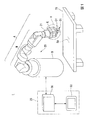
FIG. 1 is a diagram showing an example of the configuration of a
ロボット20は、アームAと、アームAを支持する支持台Bを備える単腕ロボットである。単腕ロボットは、この一例におけるアームAのような1本のアーム(腕)を備えるロボットである。なお、ロボット20は、単腕ロボットに代えて、複腕ロボットであってもよい。複腕ロボットは、2本以上のアーム(例えば、2本以上のアームA)を備えるロボットである。なお、複腕ロボットのうち、2本のアームを備えるロボットは、双腕ロボットとも称される。すなわち、ロボット20は、2本のアームを備える双腕ロボットであってもよく、3本以上のアーム(例えば、3本以上のアームA)を備える複腕ロボットであってもよい。また、ロボット20は、スカラロボットや、直角座標ロボット等の他のロボットであってもよい。直角座標ロボットは、例えば、ガントリロボットである。
The
アームAは、エンドエフェクターEと、マニピュレーターMと、力検出部21を備える。
エンドエフェクターEは、この一例において、物体を把持可能な指部を備えるエンドエフェクターである。なお、エンドエフェクターEは、当該指部を備えるエンドエフェクターに代えて、空気の吸引や磁力、治具等によって物体を持ち上げることが可能なエンドエフェクターや、他のエンドエフェクターであってもよい。
The arm A includes an end effector E, a manipulator M, and a
In this example, the end effector E is an end effector including a finger portion capable of gripping an object. Note that the end effector E may be an end effector capable of lifting an object by suction of air, magnetic force, a jig, or the like instead of the end effector including the finger portion, or another end effector.
エンドエフェクターEは、ケーブルによってロボット制御装置30と通信可能に接続されている。これにより、エンドエフェクターEは、ロボット制御装置30から取得される制御信号に基づく動作を行う。なお、ケーブルを介した有線通信は、例えば、イーサネット(登録商標)やUSB(Universal Serial Bus)等の規格によって行われる。また、エンドエフェクターEは、Wi−Fi(登録商標)等の通信規格により行われる無線通信によってロボット制御装置30と接続される構成であってもよい。
The end effector E is communicatively connected to the
マニピュレーターMは、7つの関節を備える。また、7つの関節はそれぞれ、図示しないアクチュエーターを備える。すなわち、マニピュレーターMを備えるアームAは、7軸垂直多関節型のアームである。アームAは、支持台Bと、エンドエフェクターEと、マニピュレーターMと、マニピュレーターMが備える7つの関節それぞれのアクチュエーターとによる連携した動作によって7軸の自由度の動作を行う。なお、アームAは、6軸以下の自由度で動作する構成であってもよく、8軸以上の自由度で動作する構成であってもよい。 The manipulator M has seven joints. In addition, each of the seven joints includes an actuator (not shown). That is, the arm A including the manipulator M is a 7-axis vertical multi-joint type arm. The arm A performs a motion with seven degrees of freedom by a coordinated motion of the support base B, the end effector E, the manipulator M, and the actuators of the seven joints of the manipulator M. The arm A may be configured to operate with 6 or less degrees of freedom, or may be configured to operate with 8 or more degrees of freedom.
アームAが7軸の自由度で動作する場合、アームAは、6軸以下の自由度で動作する場合と比較して取り得る姿勢が増える。これによりアームAは、例えば、動作が滑らかになり、更にアームAの周辺に存在する物体との干渉を容易に回避することができる。また、アームAが7軸の自由度で動作する場合、アームAの制御は、アームAが8軸以上の自由度で動作する場合と比較して計算量が少なく容易である。 When the arm A operates with 7 degrees of freedom, the arm A has more possible postures than when it operates with 6 or less degrees of freedom. As a result, the operation of the arm A is smooth, for example, and it is possible to easily avoid interference with an object existing around the arm A. Further, when the arm A operates with 7 degrees of freedom, the control of the arm A is easier with less calculation amount than when the arm A operates with 8 or more degrees of freedom.
マニピュレーターMが備える7つの(関節に備えられた)アクチュエーターはそれぞれ、ケーブルによってロボット制御装置30と通信可能に接続されている。これにより、当該アクチュエーターは、ロボット制御装置30から取得される制御信号に基づいて、マニピュレーターMを動作させる。また、各アクチュエーターは、エンコーダーを備えている。各エンコーダーは、各エンコーダーが備えられたアクチュエーターの回転角を示す情報をロボット制御装置30に出力する。なお、ケーブルを介した有線通信は、例えば、イーサネット(登録商標)やUSB等の規格によって行われる。また、マニピュレーターMが備える7つのアクチュエーターのうちの一部又は全部は、Wi−Fi(登録商標)等の通信規格により行われる無線通信によってロボット制御装置30と接続される構成であってもよい。
Each of the seven actuators (provided at the joints) of the manipulator M is communicatively connected to the
力検出部21は、エンドエフェクターEとマニピュレーターMの間に備えられる。力検出部21は、例えば、力センサーである。力検出部21は、ハンドHに加えられた外力を検出する。ハンドHは、この一例において、エンドエフェクターE、又はエンドエフェクターEにより把持された物体のことである。当該外力は、この一例において、ハンドHに加えられた力と、ハンドHに加えられたモーメントとの両方のことである。すなわち、力検出部21は、ハンドHに加えられた力であって、力検出座標系の各座標軸それぞれの方向に加わった力の大きさを検出する。また、力検出部21は、ハンドHに加えられたモーメントであって、当該各座標軸それぞれの周りに加えられたモーメントの大きさを検出する。力検出部21は、検出したこれらの大きさを示す力検出値を含む力検出情報を通信によりロボット制御装置30へ出力する。力検出座標系は、力検出部21とともに動くように力検出部21に対応付けられた三次元局所座標系である。なお、当該外力は、これに代えて、ハンドHに加えられた力と、ハンドHに加えられたモーメントとのうちいずれか一方のことであってもよい。
The
力検出情報は、ロボット制御装置30によるアームAの力検出情報に基づく制御である力制御に用いられる。力制御は、例えば、インピーダンス制御等のコンプライアントモーション制御のことである。なお、力検出部21は、トルクセンサー等のハンドHに加えられた外力を検出する他のセンサーであってもよい。
The force detection information is used for force control, which is control based on the force detection information of the arm A by the
力検出部21は、ケーブルによってロボット制御装置30と通信可能に接続されている。ケーブルを介した有線通信は、例えば、イーサネット(登録商標)やUSB等の規格によって行われる。なお、力検出部21とロボット制御装置30とは、Wi−Fi(登録商標)等の通信規格により行われる無線通信によって接続される構成であってもよい。
The
ロボット制御装置30は、この一例において、ロボットコントローラーである。ロボット制御装置30は、教示装置50から教示点情報を取得する。教示点情報は、教示点を示す情報である。教示点は、ロボット制御装置30がロボット20を動作させる際にロボット20の位置及び姿勢を変化させる目標となる位置及び姿勢を表す仮想的な点である。教示点には、教示点位置情報と、教示点姿勢情報と、教示点識別情報とが対応付けられている。教示点位置情報は、教示点の位置を示す情報である。また、教示点姿勢情報は、教示点の姿勢を示す情報である。教示点識別情報は、教示点を識別する情報である。
The
この一例において、教示点の位置は、教示点に対応付けられた三次元局所座標系である教示点座標系の原点のロボット座標系RCにおける位置によって表される。また、教示点の姿勢は、教示点座標系の各座標軸のロボット座標系RCにおける方向によって表される。 In this example, the position of the teaching point is represented by the position in the robot coordinate system RC of the origin of the teaching point coordinate system, which is the three-dimensional local coordinate system associated with the teaching point. The attitude of the teaching point is represented by the direction of each coordinate axis of the teaching point coordinate system in the robot coordinate system RC.
ロボット制御装置30は、教示装置50から取得した教示点情報を記憶する。また、ロボット制御装置30は、記憶した教示点情報に基づいて、ロボット20を動作させる制御信号を生成する。具体的には、ロボット制御装置30は、マニピュレーターMの各関節に備えられたエンコーダーから、各アクチュエーターの回転角を示す情報を取得する。ロボット制御装置30は、記憶した教示点情報と、取得した当該回転角を示す情報とに基づいて制御信号を生成する。ロボット制御装置30は、生成した制御信号をロボット20に送信し、当該各アクチュエーターを動作させることによってロボット20を動作させる。ここで、当該制御信号には、エンドエフェクターEを制御する制御信号も含まれる。
The
また、ロボット制御装置30は、教示装置50から各種の指示を取得する。ロボット制御装置30は、取得した指示のうちのロボット制御装置30の動作モードを切り替える動作モード切替指示に基づいて、ロボット制御装置30の動作モードを切り替える。具体的には、ロボット制御装置30は、この一例において、動作モード切替指示に基づいて、動作モードを第1モードと、第2モードと、第3モードとのいずれかに切り替える。ロボット制御装置30は、切り替えた動作モードに応じた動作をロボット20に行わせる。動作モード切替指示は、第1モードと、第2モードと、第3モードとのいずれかを示す情報を含む指示である。なお、ロボット制御装置30は、第1モードと第2モードとのいずれかに切り替える構成であってもよく、第2モードと第3モードとのいずれかに切り替える構成であってもよく、第1モードと第3モードとのいずれかに切り替える構成であってもよい。また、ロボット制御装置30は、第1モード〜第3モードの3つのモードの一部又は全部と当該3つのモードと異なる他のモードとのいずれかに切り替える構成であってもよい。
Further, the
第1モードは、この一例において、自動動作モードである。自動動作モードは、ハンドHに加えられた外力が第1所定条件を満たすまでロボット20を動かすモードである。すなわち、第1モードは、力制御によって第1所定条件が満たされるまでロボット制御装置30がロボット20を動作させるモードである。なお、第1モードは、自動動作モードに代えて、他のモードであってもよい。第1所定条件は、所定条件の一例である。第1所定条件については、後述する。
The first mode is an automatic operation mode in this example. The automatic operation mode is a mode in which the
第2モードは、この一例において、ジョグ動作モードである。ジョグ動作モードは、ロボット20が備える第1部位に加えられた外力に基づいて、ロボット20が備える第2部位を所定方向に所定量だけ移動させるモードである。以下では、一例として、第1部位と第2部位が同じ部位であり、第1部位と第2部位がハンドHである場合について説明する。すなわち、第2モードは、ハンドHに加えられた外力に基づいて、ハンドHを所定方向に所定量だけ移動させるモードである。なお、第1部位は、これに代えて、ロボット20が備える他の部位であってもよい。また、第2部位は、これに代えて、ロボット20が備える他の部位のうちの第1部位と異なる部位であってもよい。また、第2モードは、ジョグ動作モードに代えて、他のモードであってもよい。
The second mode is a jog operation mode in this example. The jog operation mode is a mode in which the second portion included in the
第3モードは、この一例において、直接動作モードである。直接動作モードは、ロボット20が備えるハンドHに加えられた外力に基づいて、当該外力が加えられた方向に当該外力の大きさに応じた量だけハンドHを動かすモードである。すなわち、第3モードは、直接教示(ダイレクトティーチング)においてユーザーがロボット20を動かす場合にロボット制御装置30がロボット20を動作させるモードである。なお、第3モードは、直接動作モードに代えて、他のモードであってもよい。以下では、第3モードによるロボット20の動作が従来から直接教示において知られている動作であるため、第3モードについての説明を省略する。
The third mode is a direct operation mode in this example. The direct operation mode is a mode in which, based on the external force applied to the hand H included in the
また、ロボット制御装置30は、教示装置50から取得した指示のうちの現在のロボット20の位置及び姿勢を示す情報を教示装置50に出力する位置姿勢情報出力指示に基づいて、当該情報を教示装置50に出力する。
Further, the
なお、ロボット制御装置30は、ロボット20の外部に設置される構成に代えて、ロボット20に内蔵される構成であってもよい。
The
教示装置50は、この一例において、ティーチングペンダントである。教示装置50は、ユーザーから受け付けた操作に基づいて、ロボット制御装置30に各種の指示を出力する。教示装置50は、動作モード切替指示をロボット制御装置30に出力することにより、ロボット制御装置30に動作モードを切り替えさせる。
The
また、教示装置50は、ロボット制御装置30に出力する指示のうちの位置姿勢情報出力指示をロボット制御装置30に出力することにより、ロボット制御装置30から現在のロボット20の位置及び姿勢を示す情報を取得する。教示装置50は、取得した当該情報に基づいて、教示点情報を生成する。教示装置50は、生成した教示点情報をロボット制御装置30に出力して記憶させる。すなわち、教示装置50は、生成した教示点情報が示す教示点をロボット制御装置30に教示する。
Further, the
教示装置50は、ケーブルによってロボット制御装置30と通信可能に接続されている。ケーブルを介した有線通信は、例えば、イーサネット(登録商標)やUSB等の規格によって行われる。なお、教示装置50とロボット制御装置30とは、Wi−Fi(登録商標)等の通信規格により行われる無線通信によって接続される構成であってもよい。
The
なお、教示装置50は、ティーチングペンダントに代えて、教示装置50の機能を有し、ロボット制御装置30に対する指示を出力することが可能なリモートコントローラー等であってもよい。
Instead of the teaching pendant, the
<ロボット制御装置がロボットを動作させる処理の概要>
以下、ロボット制御装置30がロボット20を動作させる処理の概要について説明する。
<Outline of processing in which the robot controller operates the robot>
Hereinafter, the outline of the process in which the
図1に示したように、ロボット20は、この一例において、エンドエフェクターEにより物体O1を予め把持している。すなわち、この一例におけるハンドHは、エンドエフェクターE、又はエンドエフェクターEにより把持された物体O1のことである。物体O1は、例えば、産業用の部品や部材、製品等である。なお、物体O1は、これに代えて、産業用と異なる日用品の部品や部材、製品等や、生体等の他の物体であってもよい。図1に示した例では、物体O1が直方体形状の物体として表されている。なお、物体O1の形状は、直方体形状に代えて、他の形状であってもよい。
As shown in FIG. 1, in this example, the
ロボット制御装置30は、エンドエフェクターEに予め対応付けられた位置に、エンドエフェクターEとともに動くTCP(Tool Center Point)である制御点T1を設定する。エンドエフェクターEに予め対応付けられた位置は、例えば、エンドエフェクターEにより予め把持された物体O1の重心の位置である。なお、エンドエフェクターEに対応付けられた位置は、これに代えて、エンドエフェクターEの重心の位置等の他の位置であってもよく、マニピュレーターMに対応付けられた何らかの位置であってもよい。
The
制御点T1には、制御点T1の位置を示す情報である制御点位置情報と、制御点T1の姿勢を示す情報である制御点姿勢情報とが対応付けられている。なお、制御点T1には、これらに加えて、他の情報が対応付けられる構成であってもよい。制御点位置情報及び制御点姿勢情報をロボット制御装置30が指定(決定)すると、制御点T1の位置及び姿勢が決まる。当該位置及び姿勢は、ロボット座標系RCにおける位置及び姿勢である。ロボット制御装置30は、制御点位置情報及び制御点姿勢情報を指定する。ロボット制御装置30は、アームAを動作させ、指定した制御点位置情報が示す位置に制御点T1の位置を一致させるとともに、指定した制御姿勢情報が示す姿勢に制御点T1の姿勢を一致させる。すなわち、ロボット制御装置30は、制御点位置情報及び制御点姿勢情報を指定することにより、ロボット20を動作させる。
The control point T1 is associated with control point position information that is information indicating the position of the control point T1 and control point attitude information that is information indicating the attitude of the control point T1. In addition to these, the control point T1 may be configured to be associated with other information. When the
この一例において、制御点T1の位置は、制御点座標系TC1の原点のロボット座標系RCにおける位置によって表される。また、制御点T1の姿勢は、制御点座標系TC1の各座標軸のロボット座標系RCにおける方向によって表される。制御点座標系TC1は、制御点T1とともに動くように制御点T1に対応付けられた三次元局所座標系である。なお、この一例において、前述の物体O1の位置及び姿勢は、制御点T1の位置及び姿勢によって表される。また、この一例において、制御点座標系TC1の各座標軸の方向は、前述の力検出座標系の各座標軸の方向と一致している。なお、制御点座標系TC1の各座標軸の方向は、力検出座標系の各座標軸の方向と一致しない構成であってもよい。 In this example, the position of the control point T1 is represented by the position of the origin of the control point coordinate system TC1 in the robot coordinate system RC. The attitude of the control point T1 is represented by the direction of each coordinate axis of the control point coordinate system TC1 in the robot coordinate system RC. The control point coordinate system TC1 is a three-dimensional local coordinate system associated with the control point T1 so as to move together with the control point T1. In this example, the position and orientation of the object O1 described above is represented by the position and orientation of the control point T1. Further, in this example, the directions of the coordinate axes of the control point coordinate system TC1 coincide with the directions of the coordinate axes of the force detection coordinate system described above. The directions of the coordinate axes of the control point coordinate system TC1 may not match the directions of the coordinate axes of the force detection coordinate system.
ロボット制御装置30は、ユーザーから予め入力された制御点設定情報に基づいて制御点T1を設定する。制御点設定情報は、例えば、エンドエフェクターEの重心の位置及び姿勢と制御点T1の位置及び姿勢との相対的な位置及び姿勢を示す情報である。なお、制御点設定情報は、これに代えて、エンドエフェクターEに対応付けられた何らかの位置及び姿勢と制御点T1の位置及び姿勢との相対的な位置及び姿勢を示す情報であってもよく、マニピュレーターMに対応付けられた何らかの位置及び姿勢と制御点T1の位置及び姿勢との相対的な位置及び姿勢を示す情報であってもよく、ロボット20の他の部位に対応付けられた何らかの位置及び姿勢と制御点T1の位置及び姿勢との相対的な位置及び姿勢を示す情報であってもよい。
The
以下では、一例として、前述したロボット20の位置及び姿勢が、制御点T1の位置及び姿勢である場合について説明する。なお、ロボット20の位置及び姿勢は、ロボット20の動作とともに動く他の部位の位置及び姿勢であってもよい。
In the following, as an example, a case will be described in which the position and orientation of the
ロボット制御装置30は、教示点情報に基づいてロボット20を動作させる。ロボット制御装置30は、教示点情報に基づいてロボット20を動作させる際、ユーザーにより予め入力された動作プログラムに基づいて、教示点情報が示す1以上の教示点を順に指定する。ロボット制御装置30は、指定した教示点である指定教示点に対応付けられた教示点位置情報を制御点位置情報として指定するとともに、指定教示点に対応付けられた教示点姿勢情報を制御点姿勢情報として指定する。すなわち、ロボット制御装置30は、指定教示点に基づいて制御点位置情報及び制御点姿勢情報を指定する。これにより、ロボット制御装置30は、制御点T1を指定教示点に一致させることができる。なお、この一例において、ある教示点と制御点T1とが一致することは、当該教示点の位置及び姿勢と制御点T1の位置及び姿勢とが一致することを意味する。
The
また、ロボット制御装置30は、動作モードが第1モード〜第3モードのいずれかである場合、力検出部21から取得した力検出情報に基づいてロボット20を動作させる。
Further, when the operation mode is any of the first mode to the third mode, the
具体的には、ロボット制御装置30は、力検出部21から力検出情報を取得する。そして、ロボット制御装置30は、動作モードが第1モードの場合、取得した力検出情報に基づいて、ハンドHに加えられた外力が第1所定条件を満たす状態を実現する位置及び姿勢まで制御点T1の位置及び姿勢を変化させる。ロボット制御装置30は、当該状態を実現する位置及び姿勢を、ロボット制御装置30に予め入力された力制御パラメーターと、動力学運動方程式と、当該力検出情報とに基づいて算出する。
Specifically, the
また、ロボット制御装置30は、動作モードが第2モードの場合、力検出部21から取得した力検出情報に基づいて、ハンドHに加えられた外力が第2所定条件を満たす場合、制御点T1を所定方向に所定量だけ移動させる。これにより、ロボット制御装置30は、ハンドHを所定方向に所定量だけ移動させる。
Further, when the operation mode is the second mode, the
また、ロボット制御装置30は、動作モードが第3モードの場合、力検出部21から取得した力検出情報に基づいて、ハンドHに外力が加えられた方向に、当該外力に応じた量だけ制御点T1を移動させる。ロボット制御装置30は、当該外力に応じた量を、ロボット制御装置30に予め入力された力制御パラメーターと、動力学運動方程式と、当該力検出情報とに基づいて算出する。
When the operation mode is the third mode, the
<教示装置がロボット制御装置に教示する教示点>
以下、教示装置50がロボット制御装置30に教示する教示点について説明する。
教示装置50は、ロボット制御装置30に教示する教示点として、最終目標教示点と待機教示点とを教示する。すなわち、教示装置50は、最終目標教示点及び待機教示点のそれぞれを示す教示点情報を生成する。そして、教示装置50は、生成した当該教示点情報をロボット制御装置30に出力して記憶させる。
<Teaching point that the teaching device teaches to the robot controller>
The teaching points taught by the
The
最終目標教示点は、この一例において、ロボット20が物体O1を作業台TBの上面に設定された配置領域RAに配置した場合において制御点T1が一致する教示点である。作業台TBは、この一例において、テーブル等の台である。また、作業台TBは、作業台TBの上面がロボット座標系RCのZ軸と直交するように床面に設置されている。なお、作業台TBは、これに代えて、床面や棚等の物体O1を載置可能な面を有する物体であれば、他の物体であってもよい。また、作業台TBの上面は、ロボット座標系RCのZ軸と直交しない構成であってもよい。作業台TBは、対象物の一例である。
In this example, the final target teaching point is a teaching point with which the control point T1 coincides when the
待機教示点は、この一例において、ロボット20が物体O1を配置領域RAに配置する前に制御点T1を一致させ、制御点T1を待機させる教示点である。待機教示点は、最終目標教示点からロボット座標系RCのZ軸の正方向に所定の第1距離だけ離れた教示点である。第1距離は、例えば、10センチメートルである。なお、所定距離は、これに代えて、物体O1が作業台TBに接触しない距離であれば10センチメートルより短い距離であってもよく、10センチメートルより長い距離であってもよい。
In this example, the standby teaching point is a teaching point at which the
教示装置50は、ユーザーから受け付けた操作に基づいて、ロボット制御装置30の動作モードを切り替えさせる。教示装置50により動作モードが切り替えられたロボット制御装置30は、現在の動作モードに応じた動作をロボット20に行わせ、ユーザーが所望する位置及び姿勢と制御点T1の位置及び姿勢とを一致させる。ユーザーが所望する位置及び姿勢と制御点T1の位置及び姿勢とを一致させた場合、教示装置50は、ロボット制御装置30から現在の制御点T1の位置及び姿勢を示す情報を取得する。教示装置50は、取得した当該情報に基づいて、教示点を示す教示点情報を生成する。これにより、教示装置50は、待機教示点を示す教示点情報と、最終目標教示点を示す教示点情報とを生成する。そして、教示装置50は、生成したこれらの教示点情報をロボット制御装置30に出力して記憶させる。すなわち、教示装置50は、当該教示点情報をロボット制御装置30に教示する。
The
以下では、教示装置50がロボット制御装置30に各種の指示を出力する処理と、動作モード切替指示に基づいてロボット制御装置30が動作モードを切り替える処理と、位置姿勢情報出力指示に基づいてロボット制御装置30に現在の制御点T1の位置及び姿勢を示す情報を教示装置50に出力する処理と、動作モードが第2モードの場合にロボット制御装置30がロボット20を動作させる処理と、動作モードが第1モードの場合にロボット制御装置30がロボット20を動作させる処理とについて詳しく説明する。
In the following, the processing in which the
<ロボット制御装置及び教示装置のハードウェア構成>
以下、図2を参照し、ロボット制御装置30及び教示装置50のハードウェア構成について説明する。図2は、ロボット制御装置30及び教示装置50のハードウェア構成の一例を示す図である。図2は、ロボット制御装置30のハードウェア構成(図2における30番台の符号が付された機能部)と、教示装置50のハードウェア構成(図2における50番台の符号が付された機能部)とを便宜的に重ねて示した図である。
<Hardware configuration of robot controller and teaching device>
Hereinafter, the hardware configurations of the
ロボット制御装置30は、例えば、CPU(Central Processing Unit)31と、記憶部32と、入力受付部33と、通信部34と、表示部35を備える。また、ロボット制御装置30は、通信部34を介してロボット20、教示装置50のそれぞれと通信を行う。これらの構成要素は、バスBusを介して相互に通信可能に接続されている。
The
教示装置50は、例えば、CPU51と、記憶部52と、入力受付部53と、通信部54と、表示部55を備える。また、教示装置50は、通信部54を介してロボット制御装置30と通信を行う。これらの構成要素は、バスBusを介して相互に通信可能に接続されている。
The
CPU31は、記憶部32に格納された各種プログラムを実行する。
記憶部32は、例えば、HDD(Hard Disk Drive)やSSD(Solid State Drive)、EEPROM(Electrically Erasable Programmable Read−Only Memory)、ROM(Read−Only Memory)、RAM(Random Access Memory)等を含む。なお、記憶部32は、ロボット制御装置30に内蔵されるものに代えて、USB等のデジタル入出力ポート等によって接続された外付け型の記憶装置であってもよい。記憶部32は、ロボット制御装置30が処理する各種情報や画像、動作プログラムを含む各種のプログラム、教示点情報を格納する。
The CPU 31 executes various programs stored in the
The
入力受付部33は、例えば、表示部35と一体に構成されたタッチパネルである。なお、入力受付部33は、キーボードやマウス、タッチパッド、その他の入力装置であってもよい。
通信部34は、例えば、USB等のデジタル入出力ポートやイーサネット(登録商標)ポート等を含んで構成される。
表示部35は、例えば、液晶ディスプレイパネル、あるいは、有機EL(ElectroLuminescence)ディスプレイパネルである。
The input reception unit 33 is, for example, a touch panel integrally configured with the display unit 35. The input receiving unit 33 may be a keyboard, a mouse, a touch pad, or another input device.
The communication unit 34 includes, for example, a digital input/output port such as a USB, an Ethernet (registered trademark) port, and the like.
The display unit 35 is, for example, a liquid crystal display panel or an organic EL (ElectroLuminescence) display panel.
CPU51は、記憶部52に格納された各種プログラムを実行する。
記憶部52は、例えば、HDDやSSD、EEPROM、ROM、RAM等を含む。なお、記憶部52は、教示装置50に内蔵されるものに代えて、USB等のデジタル入出力ポート等によって接続された外付け型の記憶装置であってもよい。記憶部52は、教示装置50が処理する各種情報や画像、各種のプログラムを格納する。
The CPU 51 executes various programs stored in the
The
入力受付部53は、例えば、表示部55と一体に構成されたタッチパネルである。なお、入力受付部53は、キーボードやマウス、タッチパッド、その他の入力装置であってもよい。
通信部54は、例えば、USB等のデジタル入出力ポートやイーサネット(登録商標)ポート等を含んで構成される。
表示部55は、例えば、液晶ディスプレイパネル、あるいは、有機ELディスプレイパネルである。
The
The communication unit 54 is configured to include, for example, a digital input/output port such as a USB or an Ethernet (registered trademark) port.
The
<ロボット制御装置及び教示装置の機能構成>
以下、図3を参照し、ロボット制御装置30及び教示装置50の機能構成について説明する。図3は、ロボット制御装置30及び教示装置50の機能構成の一例を示す図である。
<Functional configuration of robot controller and teaching device>
The functional configurations of the
ロボット制御装置30は、記憶部32と、制御部36を備える。
The
制御部36は、ロボット制御装置30の全体を制御する。制御部36は、力検出情報取得部361と、記憶制御部363と、情報読出部364と、動作モード切替部365と、情報出力部366と、ロボット制御部367を備える。制御部36が備えるこれらの機能部は、例えば、CPU31が、記憶部32に記憶された各種プログラムを実行することにより実現される。また、当該機能部のうちの一部又は全部は、LSI(Large Scale Integration)やASIC(Application Specific Integrated Circuit)等のハードウェア機能部であってもよい。
The
力検出情報取得部361は、力検出部21から力検出情報を取得する。
記憶制御部363は、教示装置50から取得した教示点情報を記憶部32に記憶させる。
情報読出部364は、記憶部32から各種の情報を読み出す。
動作モード切替部365は、教示装置50から取得した指示のうちの動作モード切替指示に基づいて、当該動作モード切替指示が示すモードにロボット制御装置30の動作モードを切り替える。
The force detection information acquisition unit 361 acquires force detection information from the
The
The
The operation mode switching unit 365 switches the operation mode of the
情報出力部366は、教示装置50から取得した指示のうちの位置姿勢情報出力指示に基づいて、現在の制御点T1の位置及び姿勢を示す情報を教示装置50に出力する。
ロボット制御部367は、力検出情報取得部361が力検出部21から取得した力検出情報に基づいて、ロボット制御装置30の現在の動作モードに応じた動作をロボット20に行わせる。また、ロボット制御部367は、記憶制御部363が記憶部32に記憶させた教示点情報に基づいてロボット20を動作させる。
The
The robot control unit 367 causes the
教示装置50は、記憶部52と、入力受付部53と、表示部55と、制御部56を備える。
The
制御部56は、教示装置50の全体を制御する。制御部56は、表示制御部561と、指示情報生成部563と、指示情報出力部565を備える。制御部56が備えるこれらの機能部は、例えば、CPU51が、記憶部52に記憶された各種プログラムを実行することにより実現される。また、当該機能部のうちの一部又は全部は、LSIやASIC等のハードウェア機能部であってもよい。
The
表示制御部561は、表示部55に表示させる各種の画面を生成する。表示制御部561は、生成した画面を表示部55に表示させる。
指示情報生成部563は、表示制御部561が表示部55に表示させた画面からユーザーにより受け付けられた操作に基づいて、ロボット制御装置30に出力する各種の指示を生成する。
指示情報出力部565は、指示情報生成部563が生成した指示をロボット制御装置30に出力する。
The
The instruction information generation unit 563 generates various instructions to be output to the
The instruction
<教示装置がロボット制御装置に各種の指示を出力する処理>
以下、図4を参照し、教示装置50がロボット制御装置30に各種の指示を出力する処理について説明する。図4は、教示装置50がロボット制御装置30に各種の指示を出力する処理の流れの一例を示すフローチャートである。なお、図4に示したフローチャートでは、ロボット制御装置30に各種の指示を出力する操作をユーザーから受け付けるメイン画面がすでに表示制御部561により表示部55に表示されている場合について説明する。
<Process in which the teaching device outputs various instructions to the robot controller>
Hereinafter, a process in which the
指示情報生成部563は、メイン画面においてユーザーによる操作が受け付けられるまで待機する(ステップS110)。メイン画面においてユーザーによる操作が受け付けられたと判定した場合(ステップS110−YES)、指示情報生成部563は、当該操作がロボット制御装置30の動作モードを切り替える操作であったか否かを判定する(ステップS120)。 The instruction information generation unit 563 waits until an operation by the user is accepted on the main screen (step S110). When it is determined that the operation by the user is accepted on the main screen (step S110-YES), the instruction information generation unit 563 determines whether the operation is an operation for switching the operation mode of the robot control device 30 (step S120). ).
例えば、指示情報生成部563は、ステップS110において受け付けられた操作により第1モード〜第3モードのいずれかを示す情報が選択された場合、当該操作がロボット制御装置30の動作モードを切り替える操作であったと判定する。一方、指示情報生成部563は、ステップS110において受け付けられた操作により第1モード〜第3モードのいずれかを示す情報が選択されていない場合、当該操作がロボット制御装置30の動作モードを切り替える操作ではなかったと判定する。
For example, when the information indicating any of the first mode to the third mode is selected by the operation received in step S110, the instruction information generation unit 563 is an operation of switching the operation mode of the
ステップS110において受け付けられた操作がロボット制御装置30の動作モードを切り替える操作であったと判定した場合(ステップS120−YES)、指示情報生成部563は、ステップS110において選択された情報であってモードを示す情報を含む動作モード切替指示を生成する(ステップS130)。そして、指示情報出力部565は、ステップS130において指示情報生成部563が生成した動作モード切替指示をロボット制御装置30に出力する(ステップS140)。
When it is determined that the operation accepted in step S110 is the operation of switching the operation mode of the robot control device 30 (step S120-YES), the instruction information generation unit 563 selects the mode selected in step S110. An operation mode switching instruction including the indicated information is generated (step S130). Then, the instruction
一方、ステップS110において受け付けられた操作がロボット制御装置30の動作モードを切り替える操作ではなかったと判定した場合(ステップS120−NO)、指示情報生成部563は、ステップS110において受け付けられた操作が現在のロボット20の位置及び姿勢(この一例において、現在の制御点T1の位置及び姿勢)を取得する操作であったか否かを判定する(ステップS160)。ステップS110において受け付けられた操作が現在の制御点T1の位置及び姿勢を示す情報を取得する操作であったと判定した場合(ステップS160−YES)、指示情報生成部563は、位置姿勢情報出力指示を生成する(ステップS170)。そして、指示情報生成部563は、ステップS170において生成した位置姿勢情報出力指示をロボット制御装置30に出力する(ステップS180)。 On the other hand, when it is determined that the operation accepted in step S110 is not the operation of switching the operation mode of the robot controller 30 (step S120-NO), the instruction information generation unit 563 determines that the operation accepted in step S110 is the current one. It is determined whether or not the operation is to acquire the position and orientation of the robot 20 (in this example, the current position and orientation of the control point T1) (step S160). When it is determined that the operation received in step S110 is the operation of acquiring the information indicating the current position and orientation of the control point T1 (step S160-YES), the instruction information generation unit 563 issues the position and orientation information output instruction. It is generated (step S170). Then, the instruction information generation unit 563 outputs the position/orientation information output instruction generated in step S170 to the robot control device 30 (step S180).
一方、ステップS110において受け付けられた操作が現在の制御点T1の位置及び姿勢を取得する操作ではなかったと判定した場合(ステップS160−NO)、指示情報生成部563は、ステップS110において受け付けられた操作に応じた処理を実行する(ステップS190)。当該処理には、動作モード切替指示及び位置姿勢情報出力指示以外の指示を生成する処理、及び生成した当該指示をロボット制御装置30へ出力する処理が含まれている。
On the other hand, when it is determined that the operation received in step S110 is not the operation of acquiring the current position and orientation of the control point T1 (step S160-NO), the instruction information generation unit 563 receives the operation received in step S110. A process according to is executed (step S190). The process includes a process of generating an instruction other than the operation mode switching instruction and the position/orientation information output instruction, and a process of outputting the generated instruction to the
ステップS140と、ステップS180と、ステップS190とのいずれかの処理が実行された後、指示情報生成部563は、メイン画面におけるユーザーからの操作の受け付けが終了したか否かを判定する(ステップS150)。例えば、指示情報生成部563は、メイン画面においてメイン画面を削除する操作が受け付けられた場合、メイン画面におけるユーザーからの操作の受け付けが終了したと判定する。一方、指示情報生成部563は、メイン画面においてメイン画面を削除する操作が受け付けられていない場合、メイン画面におけるユーザーからの操作の受け付けが終了していないと判定する。 After the processing of any one of step S140, step S180, and step S190 is executed, the instruction information generation unit 563 determines whether or not the acceptance of the operation from the user on the main screen is completed (step S150). ). For example, when the operation of deleting the main screen is accepted on the main screen, the instruction information generation unit 563 determines that the acceptance of the operation from the user on the main screen is completed. On the other hand, when the operation of deleting the main screen is not accepted on the main screen, the instruction information generation unit 563 determines that the acceptance of the operation from the user on the main screen is not completed.
メイン画面におけるユーザーからの操作の受け付けが終了していないと判定した場合(ステップS150−NO)、指示情報生成部563は、ステップS110に遷移し、再びメイン画面においてユーザーによる操作が受け付けられるまで待機する。一方、メイン画面におけるユーザーからの操作の受け付けが終了したと判定した場合(ステップS150−YES)、指示情報生成部563は、処理を終了する。 When it is determined that the operation of the user on the main screen has not been accepted (step S150-NO), the instruction information generation unit 563 transitions to step S110 and waits until the operation of the user is accepted on the main screen again. To do. On the other hand, when it is determined that the operation of the user on the main screen has been received (step S150-YES), the instruction information generation unit 563 ends the process.
<ロボット制御装置が動作モード切替指示に基づいて動作モードを切り替える処理>
以下、図5を参照し、ロボット制御装置30が動作モード切替指示に基づいて動作モードを切り替える処理について説明する。図5は、ロボット制御装置30が動作モード切替指示に基づいて動作モードを切り替える処理の流れの一例を示すフローチャートである。
<Process in which the robot controller switches the operation mode based on the operation mode switching instruction>
Hereinafter, with reference to FIG. 5, a process in which the
動作モード切替部365は、教示装置50から動作モード切替指示を取得するまで待機する(ステップS210)。教示装置50から動作モード切替指示を取得したと判定した場合(ステップS210−YES)、動作モード切替部365は、現在のロボット制御装置30の動作モードを、ステップS210において教示装置50から取得した動作モード切替指示が示すモードに切り替える(ステップS220)。
The operation mode switching unit 365 waits until it receives an operation mode switching instruction from the teaching device 50 (step S210). When it is determined that the operation mode switching instruction has been acquired from the teaching device 50 (step S210-YES), the operation mode switching unit 365 sets the current operation mode of the
なお、ロボット制御装置30は、例えば、ロボット20が動作モード切替スイッチを備えており、ユーザーによる動作モード切替スイッチの操作によって動作モード切替スイッチから出力される動作モード切替指示を取得する構成であってもよい。この場合、ユーザーは、動作モード切替スイッチを操作することによって、ロボット制御装置30の動作モードを切り替えることができる。動作モード切替スイッチは、例えば、エンドエフェクターEやマニピュレーターMの一部に設けられる。
The
<ロボット制御装置が位置姿勢情報出力指示に基づいて現在の制御点の位置及び姿勢を示す情報を教示装置に出力する処理>
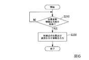
以下、図6を参照し、ロボット制御装置30が位置姿勢情報出力指示に基づいて現在の制御点T1の位置及び姿勢を示す情報を教示装置50に出力する処理について説明する。図6は、ロボット制御装置30が位置姿勢情報出力指示に基づいて現在の制御点T1の位置及び姿勢を示す情報を教示装置50に出力する処理の流れの一例を示すフローチャートである。
<Process in which the robot controller outputs information indicating the current position and orientation of the control point to the teaching device based on the position and orientation information output instruction>
A process in which the
情報出力部366は、教示装置50から位置姿勢情報出力指示を取得するまで待機する(ステップS310)。教示装置50から位置姿勢情報出力指示を取得したと情報出力部366が判定した場合(ステップS310−YES)、ロボット制御部367は、現在の制御点T1の位置及び姿勢を算出する。具体的には、ロボット制御部367は、マニピュレーターMの各関節に備えられたエンコーダーから、各アクチュエーターの回転角を示す情報を取得する。そして、ロボット制御部367は、取得した当該回転角と、順運動学とに基づいて現在の制御点T1の位置及び姿勢を算出する。そして、情報出力部366は、ロボット制御部367が算出した当該位置及び姿勢を示す情報を教示装置50に出力する(ステップS320)。
The
<動作モードが第2モードの場合にロボット制御装置がロボットを動作させる処理>
以下、図7〜図15を参照し、動作モードが第2モードの場合にロボット制御装置30がロボット20を動作させる処理について説明する。図7は、動作モードが第2モードの場合にロボット制御装置30がロボット20を動作させる処理の流れの一例を示すフローチャートである。
<Process in which the robot controller operates the robot when the operation mode is the second mode>
Hereinafter, with reference to FIGS. 7 to 15, a process of causing the
ロボット制御部367は、動作開始指示を受け付けるまで待機する(ステップS405)。動作開始指示は、ロボット20を動作させる処理を現在の動作モードによってロボット制御装置30に開始させる指示のことである。ここで、ロボット制御部367は、図示しない表示制御部が表示部35に表示させた画面においてユーザーから動作開始指示を受け付ける構成であってもよく、ユーザーから受け付けられた操作に基づいて教示装置50から出力された動作開始指示を受け付ける構成であってもよく、ロボット制御装置30及び教示装置50と別体のスイッチ等から出力された動作開始指示を受け付ける構成であってもよい。
The robot controller 367 waits until it receives an operation start instruction (step S405). The operation start instruction is an instruction to cause the
また、ロボット制御部367は、ハンドHに加えられた外力であって所定の動作開始条件を満たした外力を動作開始指示として受け付ける構成であってもよい。動作開始条件は、例えば、ハンドHに対して所定の動作開始方向に加えられた力の大きさが所定の第1閾値以上であることである。この場合、動作開始方向は、ユーザーによりロボット制御部367に予め入力された方向であり、ハンドHを並進させる並進方向である。動作開始方向は、以下において説明する所定方向と異なる方向であることが望ましいが、所定方向と同じ方向であってもよい。第1閾値は、ユーザーによりロボット制御部367に予め入力された閾値であり、如何なる閾値であってもよい。また、動作開始条件は、ハンドHに対して所定の動作開始方向に加えられた力の大きさが所定の第1閾値以上であることに代えて、ハンドHに対して所定の動作開始方向に加えられたモーメントの大きさが所定の第2閾値以上であることであってもよい。この場合、動作開始方向は、ユーザーによりロボット制御部367に予め入力された方向であり、ハンドHを回転させる回転方向である。第2閾値は、ユーザーによりロボット制御部367に予め入力された閾値であり、如何なる閾値であってもよい。また、動作開始条件は、これらの条件に代えて、他の条件であってもよい。 Further, the robot control unit 367 may be configured to receive an external force applied to the hand H and satisfying a predetermined operation start condition as an operation start instruction. The operation start condition is, for example, that the magnitude of the force applied to the hand H in the predetermined operation start direction is equal to or larger than the predetermined first threshold value. In this case, the operation start direction is the direction previously input to the robot controller 367 by the user, and is the translation direction in which the hand H is translated. The operation start direction is preferably different from the predetermined direction described below, but may be the same direction as the predetermined direction. The first threshold is a threshold preliminarily input to the robot controller 367 by the user, and may be any threshold. Further, the motion start condition is that the magnitude of the force applied to the hand H in the predetermined motion start direction is equal to or larger than the predetermined first threshold value, and It may be that the magnitude of the applied moment is equal to or larger than a predetermined second threshold value. In this case, the operation start direction is the direction previously input to the robot control unit 367 by the user, and is the rotation direction in which the hand H is rotated. The second threshold value is a threshold value previously input to the robot control unit 367 by the user, and may be any threshold value. Further, the operation start condition may be another condition instead of these conditions.
ステップS405において、動作開始指示を受け付けたと判定した場合(ステップS405−YES)、ロボット制御部367は、力検出情報取得部361が力検出部21から取得した力検出情報に基づいて、第2所定条件を満たす外力がハンドHに加えられたか否かを判定する(ステップS410)。
When it is determined in step S405 that the operation start instruction has been received (step S405-YES), the robot control unit 367 determines the second predetermined value based on the force detection information acquired by the force detection information acquisition unit 361 from the
ステップS410において第2所定条件を満たす外力がハンドHに加えられたと判定した場合(ステップS410−YES)、ロボット制御部367は、ロボット制御部367は、制御点T1を所定方向に所定量だけ移動させる(ステップS420)。 When it is determined in step S410 that the external force satisfying the second predetermined condition is applied to the hand H (step S410-YES), the robot controller 367 moves the control point T1 in the predetermined direction by the predetermined amount. (Step S420).
所定方向は、ユーザーによりロボット制御部367に予め入力された方向である。また、所定量は、ユーザーによりロボット制御部367に予め入力された移動量である。所定方向が制御点T1を並進させる並進方向であった場合、所定量は、制御点T1を並進させる並進移動量であり、例えば、1ミリメートルである。なお、この場合の所定量は、1ミリメートルより短い並進移動量であってもよく、1ミリメートルより長い並進移動量であってもよい。また、所定方向が制御点T1を回転させる回転方向であった場合、所定量は、制御点T1を回転させる回転角度であり、例えば、1度である。なお、この場合の所定量は、1度に代えて、1度より小さな回転角度であってもよく、1度より大きさ回転角度であってもよい。このように、所定方向は、並進方向と回転方向のうちいずれか一方又は両方である。 The predetermined direction is a direction previously input to the robot controller 367 by the user. Further, the predetermined amount is a movement amount that is previously input to the robot control unit 367 by the user. When the predetermined direction is the translation direction in which the control point T1 is translated, the predetermined amount is the translation movement amount in which the control point T1 is translated, and is, for example, 1 millimeter. Note that the predetermined amount in this case may be a translational movement amount shorter than 1 millimeter or a translational movement amount longer than 1 millimeter. When the predetermined direction is the rotation direction that rotates the control point T1, the predetermined amount is the rotation angle that rotates the control point T1 and is, for example, 1 degree. The predetermined amount in this case may be a rotation angle smaller than 1 degree or a rotation angle larger than 1 degree instead of 1 degree. In this way, the predetermined direction is either one or both of the translation direction and the rotation direction.
ステップS420において制御点T1を所定方向に所定量だけ移動させた後、ロボット制御部367は、動作終了指示を受け付けたか否かについて判定する(ステップS430)。動作終了指示は、ロボット20を動作させる処理をロボット制御装置30に終了させる指示のことである。ここで、ロボット制御部367は、図示しない表示制御部が表示部35に表示させた画面においてユーザーから動作終了指示を受け付ける構成であってもよく、ユーザーから受け付けられた操作に基づいて教示装置50から出力された動作終了指示を受け付ける構成であってもよく、ロボット制御装置30及び教示装置50と別体のスイッチ等から出力された動作終了指示を受け付ける構成であってもよい。
After moving the control point T1 in the predetermined direction by a predetermined amount in step S420, the robot control unit 367 determines whether or not an operation end instruction has been received (step S430). The operation end instruction is an instruction to cause the
また、ロボット制御装置30は、ハンドHに加えられた外力であって所定の動作終了条件を満たした外力を動作終了指示として受け付ける構成であってもよい。動作終了条件は、例えば、ハンドHに対して所定の動作終了方向に加えられた力の大きさが所定の第3閾値以上であることである。この場合、動作終了方向は、ユーザーによりロボット制御部367に予め入力された方向であり、ハンドHを並進させる並進方向である。動作終了方向は、前述の所定方向と異なる方向であることが望ましいが、所定方向と同じ方向であってもよい。第3閾値は、ユーザーによりロボット制御部367に予め入力された閾値であり、如何なる閾値であってもよい。また、動作終了条件は、ハンドHに対して所定の動作終了方向に加えられた力の大きさが所定の第3閾値以上であることに代えて、ハンドHに対して所定の動作終了方向に加えられたモーメントの大きさが所定の第4閾値以上であることであってもよい。この場合、動作終了方向は、ユーザーによりロボット制御部367に予め入力された方向であり、ハンドHを回転させる回転方向である。第4閾値は、ユーザーによりロボット制御部367に予め入力された閾値であり、如何なる閾値であってもよい。また、動作終了条件は、これらの条件に代えて、他の条件であってもよい。
In addition, the
ステップS430において動作終了指示を受け付けていないと判定した場合(ステップS430−NO)、ロボット制御部367は、ステップS410に遷移し、再び第2所定条件が満たされるまで待機する。一方、動作終了指示を受け付けたと判定した場合(ステップS430−YES)、ロボット制御部367は、処理を終了する。 When it is determined in step S430 that the operation end instruction has not been received (step S430-NO), the robot controller 367 transitions to step S410 and waits again until the second predetermined condition is satisfied. On the other hand, when it is determined that the operation end instruction has been received (step S430-YES), the robot controller 367 ends the process.
一方、ステップS410において第2所定条件を満たす外力がハンドHに加えられていないと判定した場合(ステップS410−NO)、ロボット制御部367は、ステップS430に遷移し、動作終了指示を受け付けたか否かについて判定する。 On the other hand, when it is determined in step S410 that the external force satisfying the second predetermined condition is not applied to the hand H (step S410-NO), the robot control unit 367 transitions to step S430 and receives the operation end instruction. Or not.
このように、ロボット制御装置30は、第2モードにおいてロボット20を動作させる際、ハンドHに加えられた外力に基づいて、ハンドHを所定方向に所定量だけ移動させる。これにより、ロボット制御部367は、第2モードにおいて、ユーザーによりハンドHに加えられる外力によるハンドHの移動量を一定に保つことができる。その結果、ロボット制御装置30は、例えば、所望の所定量がユーザーによりロボット制御部367に予め入力されることにより、制御点T1の位置及び姿勢を高い精度で所望の位置及び姿勢へと変化させることができる。
As described above, when operating the
なお、ステップS410においてユーザーがハンドHに第2所定条件を満たす外力を加え続けた場合であっても、この一例におけるロボット制御部367は、ステップS420の処理を1回のみ行う。すなわち、当該ロボット制御部367は、ステップS410においてユーザーがハンドHに第2所定条件を満たす外力を加え続けたとしても、所定方向に所定量の所定回数倍だけ制御点T1を動かさない。ユーザーが所定方向に所定量の整数倍だけ制御点T1を動かしたい場合は、ユーザーは、ハンドHに対して第2所定条件を満たす外力を加えてからハンドHに加えていた当該外力を解放するまでの作業を所定回数繰り返す必要がある。 Even when the user continues to apply the external force satisfying the second predetermined condition to the hand H in step S410, the robot control unit 367 in this example performs the process of step S420 only once. That is, even if the user continues to apply the external force satisfying the second predetermined condition to the hand H in step S410, the robot control unit 367 does not move the control point T1 in the predetermined direction a predetermined number of times a predetermined number of times. When the user wants to move the control point T1 in the predetermined direction by an integral multiple of a predetermined amount, the user applies an external force satisfying the second predetermined condition to the hand H and then releases the external force applied to the hand H. It is necessary to repeat the work up to a predetermined number of times.
第2モードにおいてロボット20を動作させ、ユーザーによりハンドHの位置及び姿勢の調整が行われた後、ロボット制御装置30は、図6に示したフローチャートの処理によって教示装置50に現在の制御点T1の位置及び姿勢を示す情報を出力する。教示装置50は、ロボット制御装置30から取得した当該情報に基づいて教示点情報を生成する。そして、教示装置50は、生成した当該教示点情報をロボット制御装置30に出力する。ロボット制御装置30は、教示装置50から取得した当該教示点情報を記憶する。例えば、ロボット制御装置30は、教示装置50から取得した待機教示点及び最終目標教示点のそれぞれを示す教示点情報を記憶する。これにより、ロボット制御装置30は、第2モードにおいて、ハンドHを所定方向に所定量だけ移動させた後に記憶された制御点T1の位置及び姿勢に基づいてロボット20を制御することができる。
After the
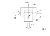
ここで、前述の第2所定条件について説明する。第2所定条件は、例えば、ハンドHに対して移動実行方向に加えられた力の大きさが第5閾値以上であることである。この場合、移動実行方向は、ユーザーによりロボット制御部367に予め入力された方向であり、ハンドHを並進させる並進方向である。第5閾値は、ユーザーによりロボット制御部367に予め入力された閾値であり、如何なる閾値であってもよい。この場合の第2所定条件における移動実行方向と、前述の所定方向との具体例を、図8〜図10のそれぞれに示した。 Here, the above-mentioned second predetermined condition will be described. The second predetermined condition is, for example, that the magnitude of the force applied to the hand H in the movement execution direction is the fifth threshold value or more. In this case, the movement execution direction is a direction previously input by the user to the robot controller 367, and is a translational direction in which the hand H is translated. The fifth threshold value is a threshold value previously input to the robot control unit 367 by the user, and may be any threshold value. Specific examples of the movement execution direction under the second predetermined condition and the above-described predetermined direction in this case are shown in FIGS. 8 to 10, respectively.
図8は、第2所定条件における移動実行方向と所定方向との具体例1を示す図である。当該具体例1は、移動実行方向及び所定方向が両方とも並進方向であり、移動実行方向と所定方向とが互いに異なる方向である場合の例である。図8には、制御点座標系TC1のX軸の負方向から正方向に向かってハンドHを見た場合の側面図が示されている。 FIG. 8 is a diagram showing a specific example 1 of the movement execution direction and the predetermined direction under the second predetermined condition. The specific example 1 is an example in which the movement execution direction and the predetermined direction are both translational directions, and the movement execution direction and the predetermined direction are different directions. FIG. 8 shows a side view when the hand H is seen from the negative direction to the positive direction of the X axis of the control point coordinate system TC1.
図8には、移動実行方向が、矢印が示す方向A1によって示されている。図8に示した例では、移動実行方向は、制御点座標系TC1のY軸の正方向である。すなわち、ロボット制御部367は、外力としてハンドHを当該正方向に並進させる力がハンドHに加えられ、当該力の大きさが第5閾値以上であった場合、制御点T1(すなわち、ハンドH)を所定方向に所定量だけ移動させる。なお、移動実行方向は、制御点座標系TC1の座標軸のうちのY軸の正方向に代えて、ハンドHを並進させる他の並進方向であってもよい。当該他の並進方向は、制御点座標系TC1のいずれかの座標軸に沿った並進方向であってもよく、制御点座標系TC1のいずれの座標軸にも沿わない並進方向であってもよい。 In FIG. 8, the movement execution direction is indicated by the direction A1 indicated by the arrow. In the example shown in FIG. 8, the movement execution direction is the positive direction of the Y axis of the control point coordinate system TC1. That is, the robot control unit 367 applies the force that translates the hand H in the positive direction as an external force to the hand H, and when the magnitude of the force is equal to or larger than the fifth threshold, the control point T1 (that is, the hand H). ) Is moved in a predetermined direction by a predetermined amount. The movement execution direction may be another translational direction in which the hand H is translated, instead of the positive direction of the Y axis of the coordinate axes of the control point coordinate system TC1. The other translation direction may be a translation direction along any coordinate axis of the control point coordinate system TC1 or may be a translation direction not along any coordinate axis of the control point coordinate system TC1.
また、図8には、所定方向が、矢印が示す方向A2によって示されている。図8に示した例では、所定方向は、制御点座標系TC1のZ軸の負方向である。すなわち、ロボット制御部367は、外力としてハンドHを制御点座標系TC1のY軸の正方向に並進させる力がハンドHに加えられ、当該力の大きさが第5閾値以上であった場合、制御点T1(すなわち、ハンドH)を制御点座標系TC1のZ軸の負方向に所定量だけ移動させる。この場合、所定量は、制御点T1を並進させる移動量である。なお、所定方向は、制御点座標系TC1の座標軸のうちのZ軸の負方向に代えて、制御点T1を並進させる他の並進方向であってもよい。当該他の並進方向は、制御点座標系TC1のいずれかの座標軸に沿った並進方向であってもよく、制御点座標系TC1のいずれの座標軸にも沿わない並進方向であってもよい。 Further, in FIG. 8, the predetermined direction is indicated by a direction A2 indicated by an arrow. In the example shown in FIG. 8, the predetermined direction is the negative direction of the Z axis of the control point coordinate system TC1. That is, when the robot control unit 367 applies a force that translates the hand H in the positive direction of the Y axis of the control point coordinate system TC1 as an external force to the hand H and the magnitude of the force is equal to or greater than the fifth threshold value, The control point T1 (that is, the hand H) is moved by a predetermined amount in the negative direction of the Z axis of the control point coordinate system TC1. In this case, the predetermined amount is a movement amount that translates the control point T1. The predetermined direction may be another translation direction in which the control point T1 is translated, instead of the negative direction of the Z axis of the coordinate axes of the control point coordinate system TC1. The other translation direction may be a translation direction along any coordinate axis of the control point coordinate system TC1 or may be a translation direction not along any coordinate axis of the control point coordinate system TC1.
図9は、第2所定条件における移動実行方向と所定方向との具体例2を示す図である。当該具体例3は、移動実行方向及び所定方向が両方とも並進方向であり、移動実行方向と所定方向とが同じ方向である場合の例である。図9には、制御点座標系TC1のX軸の負方向から正方向に向かってハンドHを見た場合の側面図が示されている。 FIG. 9 is a diagram showing a specific example 2 of the movement execution direction and the predetermined direction under the second predetermined condition. The specific example 3 is an example in which the movement execution direction and the predetermined direction are both translational directions, and the movement execution direction and the predetermined direction are the same direction. FIG. 9 shows a side view when the hand H is viewed from the negative direction to the positive direction of the X axis of the control point coordinate system TC1.
図9には、移動実行方向が、矢印が示す方向A3によって示されている。図9に示した例では、移動実行方向は、制御点座標系TC1のZ軸の負方向である。すなわち、ロボット制御部367は、外力としてハンドHを当該負方向に並進させる力がハンドHに加えられ、当該力の大きさが第5閾値以上であった場合、制御点T1(すなわち、ハンドH)を所定方向に所定量だけ移動させる。なお、移動実行方向は、制御点座標系TC1の座標軸のうちのZ軸の負方向に代えて、ハンドHを並進させる他の並進方向であってもよい。当該他の方向は、制御点座標系TC1のいずれかの座標軸に沿った並進方向であってもよく、制御点座標系TC1のいずれの座標軸にも沿わない並進方向であってもよい。 In FIG. 9, the movement execution direction is indicated by the direction A3 indicated by the arrow. In the example shown in FIG. 9, the movement execution direction is the negative direction of the Z axis of the control point coordinate system TC1. That is, when the force that translates the hand H in the negative direction is applied to the hand H as an external force and the magnitude of the force is the fifth threshold value or more, the robot control unit 367 controls the control point T1 (that is, the hand H). ) Is moved in a predetermined direction by a predetermined amount. The movement execution direction may be another translation direction in which the hand H is translated, instead of the negative direction of the Z axis of the coordinate axes of the control point coordinate system TC1. The other direction may be a translational direction along any coordinate axis of the control point coordinate system TC1 or may be a translational direction not along any coordinate axis of the control point coordinate system TC1.
また、図9には、所定方向が、矢印が示す方向A4によって示されている。図9に示した例では、所定方向は、移動実行方向と同じ方向であり、制御点座標系TC1のZ軸の負方向である。すなわち、ロボット制御部367は、外力としてハンドHを制御点座標系TC1のZ軸の負方向に並進させる力がハンドHに加えられ、当該力の大きさが第5閾値以上であった場合、制御点T1(すなわち、ハンドH)を当該負方向に所定量だけ移動させる。この場合、所定量は、制御点T1を並進させる移動量である。なお、所定方向は、制御点座標系TC1の座標軸のうちのZ軸の負方向に代えて、制御点T1を並進させる他の並進方向であってもよい。当該他の並進方向は、制御点座標系TC1のいずれかの座標軸に沿った並進方向であってもよく、制御点座標系TC1のいずれの座標軸にも沿わない並進方向であってもよい。 Further, in FIG. 9, the predetermined direction is indicated by a direction A4 indicated by an arrow. In the example shown in FIG. 9, the predetermined direction is the same direction as the movement execution direction, and is the negative direction of the Z axis of the control point coordinate system TC1. That is, when the robot control unit 367 applies a force that translates the hand H in the negative direction of the Z axis of the control point coordinate system TC1 as an external force to the hand H and the magnitude of the force is equal to or greater than the fifth threshold value, The control point T1 (that is, the hand H) is moved in the negative direction by a predetermined amount. In this case, the predetermined amount is a movement amount that translates the control point T1. The predetermined direction may be another translation direction in which the control point T1 is translated, instead of the negative direction of the Z axis of the coordinate axes of the control point coordinate system TC1. The other translation direction may be a translation direction along any coordinate axis of the control point coordinate system TC1 or may be a translation direction not along any coordinate axis of the control point coordinate system TC1.
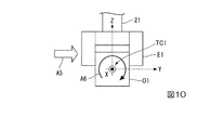
図10は、第2所定条件における移動実行方向と所定方向との具体例3を示す図である。当該具体例3は、移動実行方向が並進方向であり、所定方向が回転方向である場合の例である。図10には、制御点座標系TC1のX軸の負方向から正方向に向かってハンドHを見た場合の側面図が示されている。 FIG. 10 is a diagram showing a specific example 3 of the movement execution direction and the predetermined direction under the second predetermined condition. The specific example 3 is an example in which the movement execution direction is a translation direction and the predetermined direction is a rotation direction. FIG. 10 shows a side view when the hand H is viewed from the negative direction to the positive direction of the X axis of the control point coordinate system TC1.
図10には、移動実行方向が、矢印が示す方向A5によって示されている。図10に示した例では、移動実行方向は、制御点座標系TC1のY軸の正方向である。すなわち、ロボット制御部367は、外力としてハンドHを当該正方向に並進させる力がハンドHに加えられ、当該力の大きさが第5閾値以上であった場合、制御点T1(すなわち、ハンドH)を所定方向に所定量だけ移動させる。なお、移動実行方向は、制御点座標系TC1の座標軸のうちのY軸の正方向に代えて、ハンドHを並進させる他の並進方向であってもよい。当該他の並進方向は、制御点座標系TC1のいずれかの座標軸に沿った並進方向であってもよく、制御点座標系TC1のいずれの座標軸にも沿わない並進方向であってもよい。 In FIG. 10, the movement execution direction is indicated by the direction A5 indicated by the arrow. In the example shown in FIG. 10, the movement execution direction is the positive direction of the Y axis of the control point coordinate system TC1. That is, the robot control unit 367 applies the force that translates the hand H in the positive direction as an external force to the hand H, and when the magnitude of the force is equal to or larger than the fifth threshold, the control point T1 (that is, the hand H). ) Is moved in a predetermined direction by a predetermined amount. The movement execution direction may be another translational direction in which the hand H is translated, instead of the positive direction of the Y axis of the coordinate axes of the control point coordinate system TC1. The other translation direction may be a translation direction along any coordinate axis of the control point coordinate system TC1 or may be a translation direction not along any coordinate axis of the control point coordinate system TC1.
また、図10には、所定方向が、矢印が示す方向A6によって示されている。図10に示した例では、所定方向は、制御点座標系TC1のX軸の負方向から正方向に向かってハンドHを見た場合において当該X軸周りにハンドHを時計回りに回転させる回転方向である。すなわち、ロボット制御部367は、外力としてハンドHを制御点座標系TC1のY軸の正方向に並進させる力がハンドHに加えられ、当該力の大きさが第5閾値以上であった場合、制御点T1(すなわち、ハンドH)を、当該回転方向に所定量だけ移動させる。この場合、所定量は、制御点T1を回転させる回転量(回転角度)である。なお、所定方向は、当該回転方向に代えて、他の回転方向であってもよい。当該他の回転方向は、制御点座標系TC1のいずれかの座標軸周りの回転方向であってもよく、制御点座標系TC1のいずれの座標軸とも異なる軸周りの回転方向であってもよい。 Further, in FIG. 10, the predetermined direction is indicated by a direction A6 indicated by an arrow. In the example shown in FIG. 10, when the hand H is viewed from the negative direction of the X axis of the control point coordinate system TC1 toward the positive direction, the predetermined direction is a rotation for rotating the hand H clockwise around the X axis. Direction. That is, when the robot control unit 367 applies a force that translates the hand H in the positive direction of the Y axis of the control point coordinate system TC1 as an external force to the hand H, and the magnitude of the force is equal to or greater than the fifth threshold value, The control point T1 (that is, the hand H) is moved in the rotation direction by a predetermined amount. In this case, the predetermined amount is a rotation amount (rotation angle) for rotating the control point T1. The predetermined direction may be another rotation direction instead of the rotation direction. The other rotation direction may be a rotation direction around any coordinate axis of the control point coordinate system TC1 or may be a rotation direction around an axis different from any coordinate axis of the control point coordinate system TC1.
なお、第2所定条件は、例えば、ハンドHに対して移動実行方向に加えられたモーメントの大きさが第6閾値以上であることであってもよい。この場合、移動実行方向は、ユーザーによりロボット制御部367に予め入力された方向であり、ハンドHを回転させる回転方向である。第6閾値は、ユーザーによりロボット制御部367に予め入力された閾値であり、如何なる閾値であってもよい。この場合の第2所定条件における移動実行方向と、前述の所定方向との具体例を、図11〜図13のそれぞれに示した。 The second predetermined condition may be, for example, that the magnitude of the moment applied to the hand H in the movement execution direction is equal to or larger than the sixth threshold value. In this case, the movement execution direction is the direction previously input to the robot controller 367 by the user, and is the rotation direction in which the hand H is rotated. The sixth threshold value is a threshold value previously input to the robot controller 367 by the user, and may be any threshold value. Specific examples of the movement execution direction under the second predetermined condition in this case and the above-described predetermined direction are shown in FIGS. 11 to 13, respectively.
図11は、第2所定条件における移動実行方向と所定方向との具体例4を示す図である。当該具体例4は、移動実行方向及び所定方向の両方が回転方向であり、移動実行方向及び所定方向が同じ方向である場合の例である。図11には、制御点座標系TC1のX軸の負方向から正方向に向かってハンドHを見た場合の側面図が示されている。 FIG. 11 is a diagram showing a specific example 4 of the movement execution direction and the predetermined direction under the second predetermined condition. The specific example 4 is an example in which both the movement execution direction and the predetermined direction are rotation directions, and the movement execution direction and the predetermined direction are the same direction. FIG. 11 shows a side view when the hand H is viewed from the negative direction to the positive direction of the X axis of the control point coordinate system TC1.
図11には、移動実行方向が、矢印が示す方向A7によって示されている。図11に示した例では、移動実行方向は、制御点座標系TC1のX軸の負方向から正方向に向かってハンドHを見た場合において当該X軸周りにハンドHを時計回りに回転させる回転方向である。すなわち、ロボット制御部367は、外力としてハンドHを当該回転方向に回転させるモーメントがハンドHに加えられ、当該モーメントの大きさが第6閾値以上であった場合、制御点T1(すなわち、ハンドH)を所定方向に所定量だけ移動させる。なお、移動実行方向は、当該回転方向に代えて、ハンドHを回転させる他の回転方向であってもよい。当該他の回転方向は、制御点座標系TC1のいずれかの座標軸周りの回転方向であってもよく、制御点座標系TC1のいずれの座標軸とも異なる軸周りの回転方向であってもよい。 In FIG. 11, the movement execution direction is indicated by a direction A7 indicated by an arrow. In the example shown in FIG. 11, when the hand H is viewed from the negative direction of the X-axis of the control point coordinate system TC1 toward the positive direction, the movement execution direction rotates the hand H clockwise around the X-axis. It is the direction of rotation. That is, when the moment that rotates the hand H in the rotation direction is applied to the hand H as an external force and the magnitude of the moment is equal to or larger than the sixth threshold, the robot control unit 367 controls the control point T1 (that is, the hand H). ) Is moved in a predetermined direction by a predetermined amount. The movement execution direction may be another rotation direction that rotates the hand H, instead of the rotation direction. The other rotation direction may be a rotation direction around any coordinate axis of the control point coordinate system TC1 or may be a rotation direction around an axis different from any coordinate axis of the control point coordinate system TC1.
また、図11には、所定方向が、矢印が示す方向A7によって示されている。図11に示した例では、所定方向は、制御点座標系TC1のX軸の負方向から正方向に向かってハンドHを見た場合において当該X軸周りにハンドHを時計回りに回転させる回転方向である。すなわち、ロボット制御部367は、外力としてハンドHを当該回転方向に回転させるモーメントがハンドHに加えられ、当該モーメントの大きさが第6閾値以上であった場合、制御点T1(すなわち、ハンドH)を、当該回転方向に所定量だけ移動させる。この場合、所定量は、制御点T1を回転させる回転量(回転角度)である。なお、所定方向は、当該回転方向に代えて、制御点T1を回転させる他の回転方向であってもよい。当該他の回転方向は、制御点座標系TC1のいずれかの座標軸周りの回転方向であってもよく、制御点座標系TC1のいずれの座標軸とも異なる軸周りの回転方向であってもよい。 Further, in FIG. 11, the predetermined direction is indicated by a direction A7 indicated by an arrow. In the example shown in FIG. 11, when the hand H is viewed from the negative direction of the X axis of the control point coordinate system TC1 toward the positive direction, the predetermined direction is rotation for rotating the hand H clockwise around the X axis. Direction. That is, when the moment that rotates the hand H in the rotation direction is applied to the hand H as an external force and the magnitude of the moment is equal to or greater than the sixth threshold, the robot control unit 367 controls the control point T1 (that is, the hand H). ) Is moved by a predetermined amount in the rotation direction. In this case, the predetermined amount is a rotation amount (rotation angle) for rotating the control point T1. The predetermined direction may be another rotation direction that rotates the control point T1 instead of the rotation direction. The other rotation direction may be a rotation direction around any coordinate axis of the control point coordinate system TC1 or may be a rotation direction around an axis different from any coordinate axis of the control point coordinate system TC1.
図12は、第2所定条件における移動実行方向と所定方向との具体例5を示す図である。当該具体例5は、移動実行方向及び所定方向の両方が回転方向であり、移動実行方向及び所定方向が互いに異なる方向である場合の例である。図12には、制御点座標系TC1のX軸の負方向から正方向に向かってハンドHを見た場合の側面図が示されている。 FIG. 12 is a diagram showing a specific example 5 of the movement execution direction and the predetermined direction under the second predetermined condition. The specific example 5 is an example in which both the movement execution direction and the predetermined direction are rotation directions, and the movement execution direction and the predetermined direction are different directions. FIG. 12 shows a side view when the hand H is viewed from the negative direction to the positive direction of the X axis of the control point coordinate system TC1.
図12には、移動実行方向が、矢印が示す方向A9によって示されている。図12に示した例では、移動実行方向は、制御点座標系TC1のX軸の負方向から正方向に向かってハンドHを見た場合において当該X軸周りにハンドHを時計回りに回転させる回転方向である。すなわち、ロボット制御部367は、外力としてハンドHを当該回転方向に回転させるモーメントがハンドHに加えられ、当該モーメントの大きさが第6閾値以上であった場合、制御点T1(すなわち、ハンドH)を所定方向に所定量だけ移動させる。なお、移動実行方向は、当該回転方向に代えて、ハンドHを回転させる他の回転方向であってもよい。当該他の回転方向は、制御点座標系TC1のいずれかの座標軸周りの回転方向であってもよく、制御点座標系TC1のいずれの座標軸とも異なる軸周りの回転方向であってもよい。 In FIG. 12, the movement execution direction is indicated by the direction A9 indicated by the arrow. In the example shown in FIG. 12, when the hand H is viewed from the negative direction of the X axis of the control point coordinate system TC1 toward the positive direction, the movement execution direction rotates the hand H clockwise around the X axis. It is the direction of rotation. That is, when the moment that rotates the hand H in the rotation direction is applied to the hand H as an external force and the magnitude of the moment is equal to or greater than the sixth threshold, the robot control unit 367 controls the control point T1 (that is, the hand H). ) Is moved in a predetermined direction by a predetermined amount. The movement execution direction may be another rotation direction that rotates the hand H, instead of the rotation direction. The other rotation direction may be a rotation direction around any coordinate axis of the control point coordinate system TC1 or may be a rotation direction around an axis different from any coordinate axis of the control point coordinate system TC1.
また、図12には、所定方向が、矢印が示す方向A10によって示されている。図12に示した例では、所定方向は、制御点座標系TC1のY軸の正方向から負方向に向かってハンドHを見た場合において当該Y軸周りにハンドHを時計回りに回転させる回転方向である。すなわち、ロボット制御部367は、制御点座標系TC1のX軸の負方向から正方向に向かってハンドHを見た場合において当該X軸周りにハンドHを時計回りに回転させる回転方向に回転させるモーメントが外力としてハンドHに加えられ、当該モーメントの大きさが第6閾値以上であった場合、制御点T1(すなわち、ハンドH)を、制御点座標系TC1のY軸の正方向から負方向に向かってハンドHを見た場合において当該Y軸周りにハンドHを時計回りに回転させる回転方向に所定量だけ移動させる。この場合、所定量は、制御点T1を回転させる回転量(回転角度)である。なお、所定方向は、当該回転方向に代えて、制御点T1を回転させる他の回転方向であってもよい。当該他の回転方向は、制御点座標系TC1のいずれかの座標軸周りの回転方向であってもよく、制御点座標系TC1のいずれの座標軸とも異なる軸周りの回転方向であってもよい。 Further, in FIG. 12, the predetermined direction is indicated by a direction A10 indicated by an arrow. In the example shown in FIG. 12, when the hand H is viewed from the positive direction of the Y-axis of the control point coordinate system TC1 toward the negative direction, the predetermined direction is a rotation for rotating the hand H clockwise around the Y-axis. Direction. That is, the robot control unit 367 rotates the hand H around the X-axis in the rotation direction that rotates clockwise when the hand H is viewed from the negative direction to the positive direction of the X-axis of the control point coordinate system TC1. When a moment is applied to the hand H as an external force and the magnitude of the moment is equal to or greater than the sixth threshold value, the control point T1 (that is, the hand H) is moved from the positive direction of the Y axis of the control point coordinate system TC1 to the negative direction. When the hand H is viewed toward, the hand H is moved by a predetermined amount in the rotation direction in which the hand H is rotated clockwise around the Y axis. In this case, the predetermined amount is a rotation amount (rotation angle) for rotating the control point T1. The predetermined direction may be another rotation direction that rotates the control point T1 instead of the rotation direction. The other rotation direction may be a rotation direction around any coordinate axis of the control point coordinate system TC1 or may be a rotation direction around an axis different from any coordinate axis of the control point coordinate system TC1.
図13は、第2所定条件における移動実行方向と所定方向との具体例6を示す図である。当該具体例6は、移動実行方向が回転方向であり、所定方向が並進方向である場合の例である。図13には、制御点座標系TC1のX軸の負方向から正方向に向かってハンドHを見た場合の側面図が示されている。 FIG. 13 is a diagram showing a specific example 6 of the movement execution direction and the predetermined direction under the second predetermined condition. The specific example 6 is an example in which the movement execution direction is the rotation direction and the predetermined direction is the translation direction. FIG. 13 shows a side view when the hand H is viewed from the negative direction to the positive direction of the X axis of the control point coordinate system TC1.
図13には、移動実行方向が、矢印が示す方向A11によって示されている。図13に示した例では、移動実行方向は、制御点座標系TC1のX軸の負方向から正方向に向かってハンドHを見た場合において当該X軸周りにハンドHを時計回りに回転させる回転方向である。すなわち、ロボット制御部367は、外力としてハンドHを当該回転方向に回転させるモーメントがハンドHに加えられ、当該モーメントの大きさが第6閾値以上であった場合、制御点T1(すなわち、ハンドH)を所定方向に所定量だけ移動させる。なお、移動実行方向は、当該回転方向に代えて、ハンドHを回転させる他の回転方向であってもよい。当該他の回転方向は、制御点座標系TC1のいずれかの座標軸周りの回転方向であってもよく、制御点座標系TC1のいずれの座標軸とも異なる軸周りの回転方向であってもよい。 In FIG. 13, the movement execution direction is indicated by a direction A11 indicated by an arrow. In the example shown in FIG. 13, when the hand H is viewed from the negative direction of the X-axis of the control point coordinate system TC1 toward the positive direction, the movement execution direction rotates the hand H clockwise around the X-axis. It is the direction of rotation. That is, when the moment that rotates the hand H in the rotation direction is applied to the hand H as an external force and the magnitude of the moment is equal to or greater than the sixth threshold, the robot control unit 367 controls the control point T1 (that is, the hand H). ) Is moved in a predetermined direction by a predetermined amount. The movement execution direction may be another rotation direction that rotates the hand H, instead of the rotation direction. The other rotation direction may be a rotation direction around any coordinate axis of the control point coordinate system TC1 or may be a rotation direction around an axis different from any coordinate axis of the control point coordinate system TC1.
また、図13には、所定方向が、矢印が示す方向A12によって示されている。図13に示した例では、所定方向は、制御点座標系TC1のZ軸の負方向である。すなわち、ロボット制御部367は、制御点座標系TC1のX軸の負方向から正方向に向かってハンドHを見た場合において当該X軸周りにハンドHを時計回りに回転させる回転方向に回転させるモーメントが外力としてハンドHに加えられ、当該モーメントの大きさが第6閾値以上であった場合、制御点T1(すなわち、ハンドH)を制御点座標系TC1のZ軸の負方向に所定量だけ移動させる。この場合、所定量は、制御点T1を並進させる移動量である。なお、所定方向は、制御点座標系TC1の座標軸のうちのZ軸の負方向に代えて、制御点T1を並進させる他の並進方向であってもよい。当該他の並進方向は、制御点座標系TC1のいずれかの座標軸に沿った並進方向であってもよく、制御点座標系TC1のいずれの座標軸にも沿わない並進方向であってもよい。 Further, in FIG. 13, the predetermined direction is indicated by a direction A12 indicated by an arrow. In the example shown in FIG. 13, the predetermined direction is the negative direction of the Z axis of the control point coordinate system TC1. That is, the robot control unit 367 rotates the hand H in the rotation direction that rotates clockwise around the X axis when the hand H is viewed from the negative direction of the X axis of the control point coordinate system TC1 toward the positive direction. When the moment is applied to the hand H as an external force and the magnitude of the moment is equal to or larger than the sixth threshold value, the control point T1 (that is, the hand H) is moved by a predetermined amount in the negative direction of the Z axis of the control point coordinate system TC1. To move. In this case, the predetermined amount is a movement amount that translates the control point T1. The predetermined direction may be another translation direction in which the control point T1 is translated, instead of the negative direction of the Z axis of the coordinate axes of the control point coordinate system TC1. The other translation direction may be a translation direction along any coordinate axis of the control point coordinate system TC1 or may be a translation direction not along any coordinate axis of the control point coordinate system TC1.
なお、ロボット制御部367は、第2モードにおいて、例えば、ハンドHに対して移動実行方向に加えられた力の大きさが第5閾値以上である場合に制御点T1を所定方向に所定量だけ移動させ、当該力が第5閾値よりも大きな閾値である第7閾値以上である場合に制御点T1を所定方向と異なる方向である第2所定方向に所定量と異なる量である第2所定量だけ移動させる構成であってもよい。すなわち、ロボット制御部367は、ハンドHに対して加えられた力の段階的(離散的)な大きさの違いに応じて、当該違いに応じた方向に当該違いに応じた量だけ制御点T1を移動させる構成であってもよい。 In the second mode, for example, when the magnitude of the force applied to the hand H in the movement execution direction is the fifth threshold value or more, the robot control unit 367 sets the control point T1 in the predetermined direction by a predetermined amount. When the force is moved and the force is greater than or equal to a seventh threshold value that is a threshold value that is greater than the fifth threshold value, the control point T1 is a second predetermined amount that is different from the predetermined amount in a second predetermined direction that is a different direction from the predetermined direction. It may be configured to move only. That is, the robot control unit 367 responds to the difference in stepwise (discrete) magnitude of the force applied to the hand H in the direction corresponding to the difference and the control point T1 by the amount corresponding to the difference. May be moved.
また、ロボット制御部367は、ハンドHに加えられた外力が第2所定条件を満たす場合、所定の関節に備えられたアクチュエーターの回転角を所定方向に所定量だけ変化(移動)させる構成であってもよい。アクチュエーターの回転角を所定方向に所定量だけ変化させる場合、所定方向は、アクチュエーターの回転方向であり、所定量は、アクチュエーターの回転角である。 Further, the robot control unit 367 is configured to change (move) the rotation angle of the actuator provided in a predetermined joint in a predetermined direction by a predetermined amount when the external force applied to the hand H satisfies the second predetermined condition. May be. When changing the rotation angle of the actuator in a predetermined direction by a predetermined amount, the predetermined direction is the rotation direction of the actuator, and the predetermined amount is the rotation angle of the actuator.
また、ロボット制御部367は、力検出部21がマニピュレーターMの各関節に備えられたトルクセンサーである場合、当該各関節のいずれかに加えられた外力に基づいて、所定の関節に備えられたアクチュエーターの回転角又は制御点T1を所定方向に所定量だけ移動させる構成であってもよい。アクチュエーターの回転角を所定方向に所定量だけ移動させる場合、所定方向は、アクチュエーターの回転方向であり、所定量は、アクチュエーターの回転角である。
In addition, when the
また、ロボット制御部367は、ステップS410において、ハンドHに加えられた外力が第2所定条件を満たす状態が所定時間以上続いた場合に、ハンドHに加えられた外力が第2所定条件を満たしていると判定する構成であってもよく、ハンドHに加えられた外力が第2所定条件を満たす状態が一度でも実現した場合に、ハンドHに加えられた外力が第2所定条件を満たしていると判定する構成であってもよい。 Further, in step S410, the robot control unit 367 determines that the external force applied to the hand H satisfies the second predetermined condition when the external force applied to the hand H satisfies the second predetermined condition for a predetermined time or more. It is also possible to determine that the external force applied to the hand H satisfies the second predetermined condition even if the external force applied to the hand H satisfies the second predetermined condition even once. It may be configured to determine that there is.
<動作モードが第2モードの場合にロボット制御装置がロボットを動作させる処理の変形例>
上記において説明した所定方向は、ハンドHの部分に応じた方向であってもよい。当該部分は、外力が加えられた部分のことである。すなわち、ロボット制御部367は、ハンドHに加えられた外力に基づいて、ハンドHの部分のうちの当該外力が加わった部分に応じた方向にハンドHを所定量だけ移動させる。これにより、ロボット制御部367は、ハンドHを移動させる方向をユーザーに容易に変更させることができる。
<Modification of processing in which the robot controller operates the robot when the operation mode is the second mode>
The predetermined direction described above may be a direction corresponding to the part of the hand H. The part is a part to which an external force is applied. That is, based on the external force applied to the hand H, the robot control unit 367 moves the hand H by a predetermined amount in the direction corresponding to the part of the hand H to which the external force is applied. As a result, the robot control unit 367 can easily change the direction in which the hand H is moved by the user.
ここで、図14及び図15を参照し、所定方向がハンドHの部分に応じた方向である場合の移動実行方向と所定方向との具体例について説明する。なお、以下において説明する具体例においては、一例として、第2所定条件が、ハンドHに対して移動実行方向に加えられた力の大きさが第5閾値以上であることである場合について説明する。なお、上記において説明した具体例の場合と同様に、第2所定条件は、ハンドHに対して移動実行方向に加えられたモーメントの大きさが第6閾値以上であることであってもよい。 Here, a specific example of the movement execution direction and the predetermined direction in the case where the predetermined direction is a direction corresponding to the portion of the hand H will be described with reference to FIGS. 14 and 15. In the specific example described below, as an example, the case where the second predetermined condition is that the magnitude of the force applied to the hand H in the movement execution direction is equal to or greater than the fifth threshold value will be described. .. As in the case of the specific example described above, the second predetermined condition may be that the magnitude of the moment applied to the hand H in the movement execution direction is the sixth threshold value or more.
図14は、所定方向がハンドHの部分に応じた方向である場合の移動実行方向と所定方向との具体例1を示す図である。当該具体例1は、ハンドHの部分のうちの制御点座標系TC1のY軸から制御点座標系TC1のZ軸の正方向側の部分である上側部分に外力が加えられた場合の例である。図14には、制御点座標系TC1のX軸の負方向から正方向に向かってハンドHを見た場合の側面図が示されている。 FIG. 14 is a diagram showing a specific example 1 of the movement execution direction and the predetermined direction when the predetermined direction is a direction corresponding to the portion of the hand H. The specific example 1 is an example in which an external force is applied from the Y axis of the control point coordinate system TC1 in the part of the hand H to the upper side portion of the control point coordinate system TC1 on the positive side of the Z axis. is there. FIG. 14 shows a side view when the hand H is viewed from the negative direction to the positive direction of the X axis of the control point coordinate system TC1.
図14には、移動実行方向が、矢印が示す方向A13によって示されている。また、図14には、矢印によってハンドHに力F1が加えられた部分が示されている。図14に示した例では、移動実行方向は、制御点座標系TC1のY軸の正方向である。また、当該例では、ハンドHの部分の上側部分に外力が加えられている。すなわち、ロボット制御部367は、外力としてハンドHを当該正方向に並進させる力F1がハンドHに加えられ、当該力の大きさが第5閾値以上であった場合、制御点T1(すなわち、ハンドH)を、ハンドHの上側部分に応じた所定方向に所定量だけ移動させる。なお、移動実行方向は、制御点座標系TC1の座標軸のうちのY軸の正方向に代えて、ハンドHを並進させる他の並進方向であってもよい。当該他の並進方向は、制御点座標系TC1のいずれかの座標軸に沿った並進方向であってもよく、制御点座標系TC1のいずれの座標軸にも沿わない並進方向であってもよい。 In FIG. 14, the movement execution direction is indicated by a direction A13 indicated by an arrow. Further, in FIG. 14, a portion where the force F1 is applied to the hand H is shown by an arrow. In the example shown in FIG. 14, the movement execution direction is the positive direction of the Y axis of the control point coordinate system TC1. Further, in this example, an external force is applied to the upper part of the hand H part. That is, when the force F1 that translates the hand H in the positive direction is applied to the hand H as an external force and the magnitude of the force is equal to or greater than the fifth threshold, the robot control unit 367 controls the control point T1 (that is, the hand T). H) is moved by a predetermined amount in a predetermined direction according to the upper part of the hand H. The movement execution direction may be another translational direction in which the hand H is translated, instead of the positive direction of the Y axis of the coordinate axes of the control point coordinate system TC1. The other translation direction may be a translation direction along any coordinate axis of the control point coordinate system TC1 or may be a translation direction not along any coordinate axis of the control point coordinate system TC1.
また、図14には、所定方向が、矢印が示す方向A14によって示されている。図14に示した例では、ハンドHの上側部分に応じた所定方向は、制御点座標系TC1のZ軸の正方向である。すなわち、ロボット制御部367は、外力としてハンドHを制御点座標系TC1のY軸の正方向に並進させる力がハンドHの上側部分に加えられ、当該力の大きさが第5閾値以上であった場合、制御点T1(すなわち、ハンドH)を制御点座標系TC1のZ軸の正方向に所定量だけ移動させる。この場合、所定量は、制御点T1を並進させる移動量である。なお、所定方向は、制御点座標系TC1の座標軸のうちのZ軸の正方向に代えて、制御点T1を並進させる他の並進方向であってもよい。当該他の並進方向は、制御点座標系TC1のいずれかの座標軸に沿った並進方向であってもよく、制御点座標系TC1のいずれの座標軸にも沿わない並進方向であってもよい。また、所定方向は、並進方向に代えて、回転方向であってもよい。 Further, in FIG. 14, the predetermined direction is indicated by a direction A14 indicated by an arrow. In the example shown in FIG. 14, the predetermined direction corresponding to the upper part of the hand H is the positive direction of the Z axis of the control point coordinate system TC1. That is, the robot control unit 367 applies to the upper portion of the hand H a force that translates the hand H in the positive direction of the Y axis of the control point coordinate system TC1 as an external force, and the magnitude of the force is not less than the fifth threshold value. In this case, the control point T1 (that is, the hand H) is moved by a predetermined amount in the positive direction of the Z axis of the control point coordinate system TC1. In this case, the predetermined amount is a movement amount that translates the control point T1. Note that the predetermined direction may be another translational direction in which the control point T1 is translated, instead of the positive direction of the Z axis of the coordinate axes of the control point coordinate system TC1. The other translation direction may be a translation direction along any coordinate axis of the control point coordinate system TC1 or may be a translation direction not along any coordinate axis of the control point coordinate system TC1. Further, the predetermined direction may be a rotation direction instead of the translation direction.
図15は、所定方向がハンドHの部分に応じた方向である場合の移動実行方向と所定方向との具体例2を示す図である。当該具体例2は、ハンドHの部分のうちの制御点座標系TC1のY軸から制御点座標系TC1のZ軸の負方向側の部分である下側部分に外力が加えられた場合の例である。図15には、制御点座標系TC1のX軸の負方向から正方向に向かってハンドHを見た場合の側面図が示されている。 FIG. 15 is a diagram showing a specific example 2 of the movement execution direction and the predetermined direction in the case where the predetermined direction is the direction corresponding to the portion of the hand H. The specific example 2 is an example in which an external force is applied to a lower portion of the hand H, which is a portion on the negative side of the Z axis of the control point coordinate system TC1 from the Y axis of the control point coordinate system TC1. Is. FIG. 15 shows a side view when the hand H is viewed from the negative direction to the positive direction of the X axis of the control point coordinate system TC1.
図15には、移動実行方向が、矢印が示す方向A15によって示されている。また、図15には、矢印によってハンドHに力F2が加えられた部分が示されている。図15に示した例では、移動実行方向は、制御点座標系TC1のY軸の正方向である。また、当該例では、ハンドHの部分の下側部分に外力が加えられている。すなわち、ロボット制御部367は、外力としてハンドHを当該正方向に並進させる力F2がハンドHに加えられ、当該力の大きさが第5閾値以上であった場合、制御点T1(すなわち、ハンドH)を、ハンドHの下側部分に応じた所定方向に所定量だけ移動させる。なお、移動実行方向は、制御点座標系TC1の座標軸のうちのY軸の正方向に代えて、ハンドHを並進させる他の並進方向であってもよい。当該他の並進方向は、制御点座標系TC1のいずれかの座標軸に沿った並進方向であってもよく、制御点座標系TC1のいずれの座標軸にも沿わない並進方向であってもよい。 In FIG. 15, the movement execution direction is indicated by a direction A15 indicated by an arrow. Further, FIG. 15 shows a portion where the force F2 is applied to the hand H by an arrow. In the example shown in FIG. 15, the movement execution direction is the positive direction of the Y axis of the control point coordinate system TC1. Further, in this example, an external force is applied to the lower side portion of the hand H portion. That is, when the force F2 that translates the hand H in the positive direction is applied to the hand H as an external force and the magnitude of the force is equal to or greater than the fifth threshold value, the robot control unit 367 controls the control point T1 (that is, the hand T). H) is moved by a predetermined amount in a predetermined direction according to the lower part of the hand H. The movement execution direction may be another translational direction in which the hand H is translated, instead of the positive direction of the Y axis of the coordinate axes of the control point coordinate system TC1. The other translation direction may be a translation direction along any coordinate axis of the control point coordinate system TC1 or may be a translation direction not along any coordinate axis of the control point coordinate system TC1.
また、図15には、所定方向が、矢印が示す方向A16によって示されている。図15に示した例では、ハンドHの下側部分に応じた所定方向は、制御点座標系TC1のZ軸の負方向である。すなわち、ロボット制御部367は、外力としてハンドHを制御点座標系TC1のY軸の正方向に並進させる力がハンドHの下側部分に加えられ、当該力の大きさが第5閾値以上であった場合、制御点T1(すなわち、ハンドH)を制御点座標系TC1のZ軸の負方向に所定量だけ移動させる。この場合、所定量は、制御点T1を並進させる移動量である。なお、所定方向は、制御点座標系TC1の座標軸のうちのZ軸の負方向に代えて、制御点T1を並進させる他の並進方向であってもよい。当該他の並進方向は、制御点座標系TC1のいずれかの座標軸に沿った並進方向であってもよく、制御点座標系TC1のいずれの座標軸にも沿わない並進方向であってもよい。また、所定方向は、並進方向に代えて、回転方向であってもよい。 Further, in FIG. 15, the predetermined direction is indicated by a direction A16 indicated by an arrow. In the example shown in FIG. 15, the predetermined direction corresponding to the lower part of the hand H is the negative direction of the Z axis of the control point coordinate system TC1. That is, the robot controller 367 applies a force that translates the hand H in the positive direction of the Y axis of the control point coordinate system TC1 as an external force to the lower portion of the hand H, and the magnitude of the force is equal to or greater than the fifth threshold value. If there is, the control point T1 (that is, the hand H) is moved by a predetermined amount in the negative direction of the Z axis of the control point coordinate system TC1. In this case, the predetermined amount is a movement amount that translates the control point T1. The predetermined direction may be another translation direction in which the control point T1 is translated, instead of the negative direction of the Z axis of the coordinate axes of the control point coordinate system TC1. The other translation direction may be a translation direction along any coordinate axis of the control point coordinate system TC1 or may be a translation direction not along any coordinate axis of the control point coordinate system TC1. Further, the predetermined direction may be a rotation direction instead of the translation direction.
このように、ロボット制御部367は、ハンドHに加えられた外力に基づいて、ハンドHの部分のうちの当該外力が加わった部分に応じた方向にハンドHを所定量だけ移動させる。これにより、ロボット制御部367は、ハンドHを移動させる方向をユーザーに容易に変更させることができる。 In this way, the robot control unit 367 moves the hand H by a predetermined amount in the direction corresponding to the part of the hand H to which the external force is applied, based on the external force applied to the hand H. As a result, the robot control unit 367 can easily change the direction in which the hand H is moved by the user.
<動作モードが第1モードの場合にロボット制御装置がロボットを動作させる処理>
以下、図16〜図18を参照し、動作モードが第1モードの場合にロボット制御装置30がロボット20を動作させる処理について説明する。
<Process in which the robot controller operates the robot when the operation mode is the first mode>
Hereinafter, with reference to FIGS. 16 to 18, a process of causing the
図16は、動作モードが第1モードの場合にロボット制御装置30がロボット20を動作させる処理の流れの一例を示すフローチャートである。なお、図16に示したフローチャートでは、制御点T1がすでに待機教示点と一致している場合について説明する。例えば、ロボット制御装置30は、前述の第2モード又は第3モードにおいて、ユーザーによりハンドHに加えられた外力に基づいて、制御点T1を待機教示点と一致させることができる。また、ロボット制御装置30の動作モードがすでに第1モードに切り替えられている場合について説明する。
FIG. 16 is a flowchart showing an example of the flow of processing in which the
ロボット制御部367は、動作開始指示を受け付けるまで待機する(ステップS505)。ここで、ロボット制御部367は、図示しない表示制御部が表示部35に表示させた画面においてユーザーから動作開始指示を受け付ける構成であってもよく、ユーザーから受け付けられた操作に基づいて教示装置50から出力された動作開始指示を受け付ける構成であってもよく、ロボット制御装置30及び教示装置50と別体のスイッチ等から出力された動作開始指示を受け付ける構成であってもよい。また、ロボット制御部367は、ハンドHに加えられた外力であって所定の動作開始条件を満たした外力を動作開始指示として受け付ける構成であってもよい。
The robot controller 367 waits until it receives an operation start instruction (step S505). Here, the robot control unit 367 may be configured to receive an operation start instruction from the user on a screen displayed on the display unit 35 by a display control unit (not shown), and the
ステップS505において、動作開始指示を受け付けたと判定した場合(ステップS505−YES)、ロボット制御部367は、力検出情報取得部361が力検出部21から取得した力検出情報に基づいて、ハンドHに加えられた外力が第1所定条件を満たす状態を実現する位置及び姿勢まで制御点T1の位置及び姿勢を変化させ始める(ステップS510)。具体的には、ロボット制御部367は、当該状態を実現する位置及び姿勢を、ロボット制御部367に予め入力された力制御パラメーターと、動力学運動方程式と、当該力検出情報とに基づいて算出する。そして、ロボット制御部367は、制御点T1の位置及び姿勢を、算出した位置及び姿勢へと変化させ始める。
When it is determined in step S505 that the operation start instruction has been received (step S505-YES), the robot control unit 367 determines that the hand H is based on the force detection information acquired by the force detection information acquisition unit 361 from the
第1所定条件は、この一例において、以下に示す1)〜3)の3つの条件を満たすことである。なお、第1所定条件は、当該3つの条件の一部又は全部を満たす構成に代えて、他の条件を満たす構成であってもよく、当該3つの条件を満たす構成に加えて、他の条件を満たす構成であってもよい。 In this example, the first predetermined condition is to satisfy the following three conditions 1) to 3). Note that the first predetermined condition may be a configuration that satisfies other conditions instead of the configuration that satisfies some or all of the three conditions. In addition to the configuration that satisfies the three conditions, other conditions It may be a configuration that satisfies the above condition.
1)ハンドHに加えられた力のうちの制御点座標系TC1のZ軸の正方向に加えられた力の大きさが所定値以上であること
2)ハンドHに加えられた力のうちの制御点座標系TC1のX軸方向及びY軸方向に加えられた力の大きさが0[N]であること
3)ハンドHに加えられたモーメントのうちの制御点座標系TC1の各座標軸それぞれの周りのモーメントの大きさが0[N・m]であること
1) Of the forces applied to the hand H, the magnitude of the force applied in the positive direction of the Z-axis of the control point coordinate system TC1 is greater than or equal to a predetermined value. 2) Of the forces applied to the hand H The magnitude of the force applied in the X-axis direction and the Y-axis direction of the control point coordinate system TC1 is 0 [N] 3) Each coordinate axis of the control point coordinate system TC1 in the moment applied to the hand H The magnitude of the moment around is 0 [N·m]
なお、上記の1)の条件は、ハンドHに加えられた力のうちの制御点座標系TC1のZ軸の負方向に加えられた力の大きさが所定値以上であることであってもよく、ハンドHに加えられた力のうちの制御点座標系TC1のX軸の正方向又は負方向に加えられた力の大きさが所定値以上であることであってもよく、ハンドHに加えられた力のうちの制御点座標系TC1のY軸の正方向又は負方向に加えられた力の大きさが所定値以上であることであってもよい。また、この一例において、制御点座標系TC1のZ軸の正方向は、並進方向であり、第1方向の一例である。また、制御点座標系TC1の各座標軸それぞれの周りの回転方向は、第2方向の一例である。 Note that the condition 1) above is that the magnitude of the force applied to the hand H in the negative direction of the Z axis of the control point coordinate system TC1 is equal to or greater than a predetermined value. Of the forces applied to the hand H, the magnitude of the force applied in the positive or negative direction of the X axis of the control point coordinate system TC1 may be equal to or larger than a predetermined value. It may be that the magnitude of the force applied in the positive direction or the negative direction of the Y axis of the control point coordinate system TC1 among the applied forces is equal to or larger than a predetermined value. Further, in this example, the positive direction of the Z axis of the control point coordinate system TC1 is the translation direction, which is an example of the first direction. The rotation direction around each coordinate axis of the control point coordinate system TC1 is an example of the second direction.
第1所定条件が上記の1)〜3)の3つの条件のそれぞれを満たすことである場合、ロボット制御部367は、制御点T1の姿勢を保持したまま、制御点T1の位置を制御点座標系TC1のZ軸の正方向へ移動させる。ここで、図17を参照し、ステップS510の処理について説明する。図17は、ステップS510において制御点T1の位置及び姿勢が変化し始める直前のタイミングにおけるハンドHと作業台TBとの位置関係の一例を示す図である。図17には、制御点座標系TC1のX軸の負方向から正方向に向かってハンドHを見た場合の側面図が示されている。図17に示したように、当該タイミングにおいて、制御点T1は、待機教示点P1と一致している。また、図17では、側面図では配置領域RAの範囲が判別しづらいため、配置領域RAを太線によって示してある。 When the first predetermined condition is to satisfy each of the above three conditions 1) to 3), the robot controller 367 determines the position of the control point T1 while maintaining the posture of the control point T1. The system TC1 is moved in the positive direction of the Z axis. Here, the process of step S510 will be described with reference to FIG. FIG. 17 is a diagram showing an example of the positional relationship between the hand H and the workbench TB immediately before the position and orientation of the control point T1 start changing in step S510. FIG. 17 shows a side view when the hand H is seen from the negative direction to the positive direction of the X axis of the control point coordinate system TC1. As shown in FIG. 17, at the timing, the control point T1 coincides with the standby teaching point P1. Further, in FIG. 17, since it is difficult to determine the range of the placement area RA in the side view, the placement area RA is indicated by a thick line.
図17に示した例では、ハンドHには、当該タイミングにおいて外力が加えられていない。すなわち、ロボット制御部367は、当該タイミングにおいてハンドHに加えられたモーメントがすでに上記の3)の条件を満たしているため、ステップS510において制御点T1の姿勢を保持する。また、ロボット制御部367は、当該タイミングにおいてハンドHに加えられた力のうちの制御点座標系TC1のX軸方向及びY軸方向に加えられた力がすでに上記の2)の条件を満たしているため、ステップS510において制御点T1の当該X軸方向及びY軸方向の位置を保持する。そして、ロボット制御部367は、当該タイミングにおいてハンドHに加えられた力のうちの制御点座標系TC1のZ軸の正方向に加えられた力が上記の1)の条件を満たしていないため、ステップS510においてハンドHに当該正方向への力が加わるようにハンドHを当該正方向と反対の方向へ移動させ始める。図17では、当該正方向を矢印が示す方向A17によって示されている。 In the example shown in FIG. 17, no external force is applied to the hand H at the timing. That is, the robot control unit 367 holds the posture of the control point T1 in step S510 because the moment applied to the hand H at the timing has already satisfied the condition 3). Further, the robot controller 367 determines that the force applied in the X-axis direction and the Y-axis direction of the control point coordinate system TC1 among the forces applied to the hand H at the timing already satisfies the condition 2) above. Therefore, in step S510, the position of the control point T1 in the X-axis direction and the Y-axis direction is held. Then, the robot control unit 367 does not satisfy the above condition 1) because the force applied to the positive direction of the Z axis of the control point coordinate system TC1 among the forces applied to the hand H at the timing is not satisfied. In step S510, the hand H is started to move in the direction opposite to the positive direction so that the force in the positive direction is applied to the hand H. In FIG. 17, the positive direction is indicated by a direction A17 indicated by an arrow.
ステップS510において制御点T1の位置及び姿勢を変化させ始めた後、ロボット制御部367は、力検出情報取得部361が力検出部21から取得した力検出情報に基づいて、上記の第1所定条件が満たされるまでステップS510において開始した制御点T1の移動を継続する(ステップS520)。第1所定条件が満たされたと判定した場合(ステップS520−YES)、ロボット制御部367は、ユーザーが所望する位置及び姿勢に制御点T1の位置及び姿勢が一致したと判定し、制御点T1の位置及び姿勢の変化を停止させる(ステップS530)。
After starting to change the position and orientation of the control point T1 in step S510, the robot control unit 367 determines, based on the force detection information acquired by the force detection information acquisition unit 361 from the
ここで、図18を参照し、ステップS530の処理について説明する。図18は、ステップS530において制御点T1の位置及び姿勢の変化が停止される直前のタイミングにおけるハンドHと作業台TBとの位置関係の一例を示す図である。図18には、制御点座標系TC1のX軸の負方向から正方向に向かってハンドHを見た場合の側面図が示されている。また、図18では、側面図では配置領域RAの範囲が判別しづらいため、配置領域RAを太線によって示してある。図18に示した例では、ハンドHには、当該タイミングにおいて作業台TBからの垂直効力が外力として加えられている。ステップS510において開始した制御点T1の位置及び姿勢の変化によって当該垂直効力が所定値以上となった場合、ロボット制御部367は、当該タイミングにおいてハンドHに加えられた外力が第1所定条件を満たしているため、制御点T1の位置及び姿勢の変化を停止させる。 Here, the process of step S530 will be described with reference to FIG. FIG. 18 is a diagram showing an example of the positional relationship between the hand H and the workbench TB immediately before the change in the position and posture of the control point T1 is stopped in step S530. FIG. 18 shows a side view when the hand H is viewed from the negative direction to the positive direction of the X axis of the control point coordinate system TC1. Further, in FIG. 18, since it is difficult to determine the range of the placement area RA in the side view, the placement area RA is indicated by a thick line. In the example shown in FIG. 18, the vertical effect from the workbench TB is applied to the hand H as an external force at the timing. When the vertical effectiveness becomes equal to or greater than the predetermined value due to the change in the position and orientation of the control point T1 started in step S510, the robot control unit 367 determines that the external force applied to the hand H at the timing satisfies the first predetermined condition. Therefore, the change in the position and orientation of the control point T1 is stopped.
このように、ロボット制御装置30は、第1モードによってロボット20を動作させる際、ハンドHに加えられた外力が第1所定条件を満たす状態を実現する位置及び姿勢まで制御点T1の位置及び姿勢を変化させる。これにより、ロボット制御部367は、第1モードにおいて、ユーザーによりハンドHに外力が加えられることなく、ロボット20の位置及び姿勢を、作業台TBに対応付けられた所望の位置及び姿勢へと高い精度で変化させることができる。その結果、ロボット制御装置30は、例えば、ユーザーが所望する条件が第1所定条件としてロボット制御部367に入力された場合、ハンドHの位置及び姿勢の調整を精度よく行うことができる。
As described above, when the
第1モードにおいてロボット20を動作させ、ユーザーによりハンドHの位置及び姿勢の調整が行われた後、ロボット制御装置30は、図6に示したフローチャートの処理によって教示装置50に現在の制御点T1の位置及び姿勢を示す情報を出力する。教示装置50は、ロボット制御装置30から取得した当該情報に基づいて教示点情報を生成する。そして、教示装置50は、生成した当該教示点情報をロボット制御装置30に出力する。ロボット制御装置30は、教示装置50から取得した当該教示点情報を記憶する。例えば、ロボット制御装置30は、教示装置50から取得した最終目標教示点を示す教示点情報を記憶する。これにより、ロボット制御装置30は、第1モードにおいて、第1所定条件を満たされた場合に記憶された制御点T1の位置及び姿勢に基づいてロボット20を動作させることができる。
After the
<第1モード及び第2モードによる微調整>
上記において説明したように、第1モード及び第2モードにおいてロボット20を動作させた場合、ロボット制御装置30は、ハンドHの位置及び姿勢の調整を精度よく行うことができる。すなわち、ロボット制御装置30は、ハンドHの位置及び姿勢の微調整を行うことができる。
<Fine adjustment in the first mode and the second mode>
As described above, when the
このような微調整は、例えば、直接教示において行われる。直接教示では、ロボット制御装置30が第3モードによってロボット20を動作させる。このため、ユーザーは、ハンドHに外力を加えることによって、ハンドHの位置及び姿勢を変更する。しかし、ユーザーが所望する外力を、ユーザーが精度よくハンドHに加えることは困難である。従って、ユーザーは、第3モードによってロボット制御装置30にロボット20を動作させることによってハンドHの位置及び姿勢を、ユーザーが所望する位置及び姿勢に近づけた後、第1モードと第2モードとのうちいずれか一方又は両方によってロボット制御装置30にロボット20を動作させる。すなわち、ロボット制御装置30は、ハンドHの位置及び姿勢を記憶する直接教示において、ハンドHに加わる外力が第1所定条件を満たすまでロボット20を動かす第1モードと、ハンドHに加えられた外力に基づきロボット20を動かす第2モードとのうちいずれか一方又は両方によって教示する。これにより、ロボット制御装置30は、ハンドHの位置及び姿勢をユーザーが所望する位置及び姿勢に精度よく一致させることができる。
Such fine adjustment is performed by direct teaching, for example. In direct teaching, the
なお、このような微調整は、直接教示に代えて、ユーザーがジョグキーを操作することによってロボット制御装置30にロボット20を動作させ、ロボット制御装置30にハンドHの位置及び姿勢を記憶させるオンライン教示(オンラインティーチング)や、これから開発される方法に基づく教示において行われてもよい。
For such fine adjustment, instead of direct teaching, online teaching in which the user operates the jog key to cause the
以上のように、制御装置25は、ロボット(この一例において、ロボット20)の位置及び姿勢を記憶する際、ハンド(この一例において、ハンドH)に加わる外力が所定条件(この一例において、第1所定条件)を満たすまでロボットを動かす第1モードと、ロボットが備える第1部位(この一例において、ハンドH)に加えられた外力に基づきロボットを動かす第2モードとを切り替える。これにより、制御装置25は、第1モードと第2モードとのいずれかによって、ロボットの位置及び姿勢を高い精度で所望の位置及び姿勢へと変化させることができる。
As described above, when the
また、制御装置25は、第1モードにおいて、所定条件が満たされるまで、力検出部(この一例において、力検出部21)の出力に基づく制御によってハンドを対象物(この一例において、作業台TB)に近づける。これにより、制御装置25は、第1モードにおいて、ユーザーによりハンドに外力を加えさせることなく、ロボットの位置及び姿勢を、対象物に対応付けられた所望の位置及び姿勢へと高い精度で変化させることができる。
Further, in the first mode, the
また、制御装置25は、第1モードにおいて、ハンドに加わる外力のうちの少なくとも第1方向に向かう外力が0より大きくなり、且つ、ハンドに加わる外力のうちの少なくとも第1方向(この一例において、制御点座標系TC1のZ軸の正方向)と異なる第2方向(この一例において、制御点座標系TC1の各座標軸それぞれの周りの回転方向)に向かう外力が0となるまでロボットを動かす。これにより、制御装置25は、第1モードにおいて、ロボットの姿勢を保持したまま、第1方向と反対の方向に向かってロボットの位置を移動させることができる。
Further, in the first mode, the
また、制御装置25は、第1モードにおいて、ハンドに加わる力のうちの少なくとも並進方向である第1方向に向かう力が0より大きくなり、且つ、回転方向である第2方向に向かうモーメントが0となるまでロボットを動かす。これにより、制御装置25は、第1モードにおいて、ロボットの姿勢を保持したまま、並進方向である第1方向と反対の方向に向かってロボットの位置を移動させることができる。
Further, in the
また、制御装置25は、第1モードにおいて、所定条件が満たされた場合、現在のロボットの位置及び姿勢(この一例において、制御点T1の位置及び姿勢)を記憶する。これにより、制御装置25は、第1モードにおいて、所定条件を満たされた場合に記憶されたロボットの位置及び姿勢に基づいてロボットを動作させることができる。
In addition, the
また、制御装置25は、第2モードにおいて、ロボットが備える第1部位(この一例において、ハンドH)に加えられた外力に基づいて、ロボットが備える第2部位(この一例において、ハンドH)を所定方向に所定量だけ移動させる。これにより、制御装置25は、第2モードにおいて、ユーザーにより第1部位に加えられる外力基づいて、ロボットの位置及び姿勢を高い精度で所望の位置及び姿勢へと変化させることができる。
In addition, in the second mode, the
また、制御装置25は、第2部位を所定方向に所定量だけ移動させた後、現在のロボットの位置及び姿勢を記憶する。これにより、制御装置25は、第2モードにおいて、第2部位を所定方向に所定量だけ移動させた後に記憶されたロボットの位置及び姿勢に基づいてロボットを制御することができる。
Further, the
また、制御装置25は、第2部位を並進方向と回転方向のうちいずれか一方又は両方に所定量だけ移動させた後、現在のハンドの位置及び姿勢を記憶する。これにより、制御装置25は、第2モードにおいて、第2部位を並進方向と回転方向のうちいずれか一方又は両方に所定量だけ移動させた後に記憶された位置及び姿勢に基づいてロボットを制御することができる。
In addition, the
また、制御装置25は、ロボットが備える第1部位に加えられた外力に応じて、第1部位の部分のうちの当該外力が加わった部分(この一例において、上側部分又は下側部分)に応じた方向に第2部位を所定量だけ移動させる。これにより、制御装置25は、第2部位を移動させる方向をユーザーに容易に変更させることができる。
In addition, the
以上、この発明の実施形態を、図面を参照して詳述してきたが、具体的な構成はこの実施形態に限られるものではなく、この発明の要旨を逸脱しない限り、変更、置換、削除等されてもよい。 Although the embodiment of the present invention has been described in detail above with reference to the drawings, the specific configuration is not limited to this embodiment, and modifications, replacements, deletions, etc. are possible without departing from the gist of the present invention. May be done.
また、以上に説明した装置(例えば、制御装置25、ロボット制御装置30、教示装置50)における任意の構成部の機能を実現するためのプログラムを、コンピューター読み取り可能な記録媒体に記録し、そのプログラムをコンピューターシステムに読み込ませて実行するようにしてもよい。なお、ここでいう「コンピューターシステム」とは、OS(Operating System)や周辺機器等のハードウェアを含むものとする。また、「コンピューター読み取り可能な記録媒体」とは、フレキシブルディスク、光磁気ディスク、ROM、CD(Compact Disk)−ROM等の可搬媒体、コンピューターシステムに内蔵されるハードディスク等の記憶装置のことをいう。さらに「コンピューター読み取り可能な記録媒体」とは、インターネット等のネットワークや電話回線等の通信回線を介してプログラムが送信された場合のサーバーやクライアントとなるコンピューターシステム内部の揮発性メモリー(RAM)のように、一定時間プログラムを保持しているものも含むものとする。
In addition, a program for realizing the function of an arbitrary component in the above-described device (for example, the
また、上記のプログラムは、このプログラムを記憶装置等に格納したコンピューターシステムから、伝送媒体を介して、あるいは、伝送媒体中の伝送波により他のコンピューターシステムに伝送されてもよい。ここで、プログラムを伝送する「伝送媒体」は、インターネット等のネットワーク(通信網)や電話回線等の通信回線(通信線)のように情報を伝送する機能を有する媒体のことをいう。
また、上記のプログラムは、前述した機能の一部を実現するためのものであってもよい。さらに、上記のプログラムは、前述した機能をコンピューターシステムにすでに記録されているプログラムとの組み合わせで実現できるもの、いわゆる差分ファイル(差分プログラム)であってもよい。
Further, the above program may be transmitted from a computer system in which the program is stored in a storage device or the like to another computer system via a transmission medium or by a transmission wave in the transmission medium. Here, the "transmission medium" for transmitting the program refers to a medium having a function of transmitting information such as a network (communication network) such as the Internet or a communication line (communication line) such as a telephone line.
Further, the above program may be a program for realizing some of the functions described above. Further, the above program may be a so-called difference file (difference program) that can realize the functions described above in combination with the program already recorded in the computer system.
1…ロボットシステム、20…ロボット、21…力検出部、30…ロボット制御装置、31、51…CPU、32、52…記憶部、33、53…入力受付部、34、54…通信部、35、55…表示部、36、56…制御部、361…力検出情報取得部、363…記憶制御部、364…情報読出部、365…動作モード切替部、366…情報出力部、367…ロボット制御部、561…表示制御部、563…指示情報生成部、565…指示情報出力部
DESCRIPTION OF
Claims (7)
制御装置。 When storing the position and orientation of a robot having a hand and a force detection unit, a first mode in which the robot is moved until the external force detected by the force detection unit satisfies a predetermined condition, and a pre-input based on the external force Switching between a second mode of moving the hand of the robot by a predetermined amount input in a predetermined direction ,
Control device.
請求項1に記載の制御装置。 In the first mode, the hand is brought closer to the object by force control based on the external force until the predetermined condition is satisfied,
The control device according to claim 1.
請求項1又は2に記載の制御装置。 The predetermined condition is that the external force in the first direction becomes larger than 0 and the external force in the second direction becomes 0.
The control device according to claim 1.
前記第2方向は、回転方向である、
請求項3に記載の制御装置。 The first direction is a translational direction,
The second direction is a rotational direction,
The control device according to claim 3.
請求項1から4のうちいずれか一項に記載の制御装置。 In the first mode, when the predetermined condition is satisfied, the position and orientation of the robot at the time when the predetermined condition is satisfied are stored.
The control device according to any one of claims 1 to 4.
請求項1から5のうちのいずれか一項に記載の制御装置。 The predetermined direction includes a translational direction or a rotational direction,
The control device according to any one of claims 1 to 5 .
前記制御装置に制御されるロボットと、
を備えるロボットシステム。 The control device according to any one of claims 1 to 6 ,
A robot controlled by the control device,
Robot system with.
Priority Applications (5)
| Application Number | Priority Date | Filing Date | Title |
|---|---|---|---|
| JP2016054959A JP6733239B2 (en) | 2016-03-18 | 2016-03-18 | Controller and robot system |
| US15/458,280 US10350768B2 (en) | 2016-03-18 | 2017-03-14 | Control device, robot, and robot system |
| CN202211704841.1A CN116141290A (en) | 2016-03-18 | 2017-03-16 | Robot system and control method for robot |
| CN201710156754.XA CN107414842B (en) | 2016-03-18 | 2017-03-16 | Control device, robot, and robot system |
| US16/430,513 US11090814B2 (en) | 2016-03-18 | 2019-06-04 | Robot control method |
Applications Claiming Priority (1)
| Application Number | Priority Date | Filing Date | Title |
|---|---|---|---|
| JP2016054959A JP6733239B2 (en) | 2016-03-18 | 2016-03-18 | Controller and robot system |
Related Child Applications (1)
| Application Number | Title | Priority Date | Filing Date |
|---|---|---|---|
| JP2020113964A Division JP2020157475A (en) | 2020-07-01 | 2020-07-01 | Control device, robot system, and robot control method |
Publications (3)
| Publication Number | Publication Date |
|---|---|
| JP2017164876A JP2017164876A (en) | 2017-09-21 |
| JP2017164876A5 JP2017164876A5 (en) | 2019-04-04 |
| JP6733239B2 true JP6733239B2 (en) | 2020-07-29 |
Family
ID=59847361
Family Applications (1)
| Application Number | Title | Priority Date | Filing Date |
|---|---|---|---|
| JP2016054959A Active JP6733239B2 (en) | 2016-03-18 | 2016-03-18 | Controller and robot system |
Country Status (3)
| Country | Link |
|---|---|
| US (2) | US10350768B2 (en) |
| JP (1) | JP6733239B2 (en) |
| CN (2) | CN107414842B (en) |
Families Citing this family (17)
| Publication number | Priority date | Publication date | Assignee | Title |
|---|---|---|---|---|
| US11093590B2 (en) * | 2015-08-31 | 2021-08-17 | Avaya Inc. | Selection of robot operation mode from determined compliance with a security criteria |
| JP6733239B2 (en) | 2016-03-18 | 2020-07-29 | セイコーエプソン株式会社 | Controller and robot system |
| JP2018171668A (en) | 2017-03-31 | 2018-11-08 | セイコーエプソン株式会社 | Control device, robot, and robot system |
| JP6870433B2 (en) * | 2017-03-31 | 2021-05-12 | セイコーエプソン株式会社 | Control device and robot system |
| JP6690626B2 (en) * | 2017-10-31 | 2020-04-28 | 株式会社安川電機 | Robot system and robot evacuation method |
| JP7042594B2 (en) * | 2017-11-27 | 2022-03-28 | アズビル株式会社 | Actuator operation switching device |
| JP7135437B2 (en) | 2018-05-22 | 2022-09-13 | セイコーエプソン株式会社 | ROBOT SYSTEM CONTROL METHOD AND ROBOT SYSTEM |
| JP7124439B2 (en) * | 2018-05-22 | 2022-08-24 | セイコーエプソン株式会社 | Control device and robot system |
| JP7131087B2 (en) * | 2018-05-31 | 2022-09-06 | セイコーエプソン株式会社 | ROBOT SYSTEM CONTROL METHOD AND ROBOT SYSTEM |
| JP2020001099A (en) | 2018-06-25 | 2020-01-09 | セイコーエプソン株式会社 | Control device, robot and robot system |
| JP7211007B2 (en) * | 2018-10-30 | 2023-01-24 | セイコーエプソン株式会社 | Control device, robot system and control method |
| JP7053443B2 (en) * | 2018-12-07 | 2022-04-12 | ファナック株式会社 | Control device for robots that perform manual operations with the operating device |
| JP7207010B2 (en) * | 2019-02-27 | 2023-01-18 | セイコーエプソン株式会社 | Robot system and its control method |
| JP2021062436A (en) * | 2019-10-11 | 2021-04-22 | セイコーエプソン株式会社 | Teaching method |
| JP2021062443A (en) * | 2019-10-11 | 2021-04-22 | セイコーエプソン株式会社 | Teaching method |
| JP7415447B2 (en) * | 2019-10-31 | 2024-01-17 | セイコーエプソン株式会社 | robot system |
| JP2021160048A (en) * | 2020-04-01 | 2021-10-11 | アズビル株式会社 | Teaching device |
Family Cites Families (67)
| Publication number | Priority date | Publication date | Assignee | Title |
|---|---|---|---|---|
| JPS60252911A (en) * | 1984-05-30 | 1985-12-13 | Hitachi Ltd | Robot containing operation key at its mobile part |
| JPH0741565B2 (en) * | 1986-12-23 | 1995-05-10 | キヤノン株式会社 | Robot teaching method |
| JP2669075B2 (en) | 1989-10-06 | 1997-10-27 | 日立建機株式会社 | Direct teaching device and position teaching method for robot position and posture |
| JPH0440506A (en) * | 1990-06-06 | 1992-02-10 | Murata Mach Ltd | Teaching device for robot |
| JPH0647688A (en) | 1991-09-30 | 1994-02-22 | Yamaha Corp | Instruction device of robot |
| JP3207231B2 (en) | 1992-01-24 | 2001-09-10 | 松下電器産業株式会社 | Robot direct teaching method |
| JPH05237784A (en) * | 1992-02-28 | 1993-09-17 | Matsushita Electric Ind Co Ltd | Direct teaching device of articulated robot |
| JPH05285870A (en) * | 1992-04-03 | 1993-11-02 | Matsushita Electric Ind Co Ltd | Direct teaching device for multijoint robot |
| JP3274272B2 (en) * | 1994-03-08 | 2002-04-15 | ファナック株式会社 | Manual feeding method of coordinate system and robot controller |
| JP3418456B2 (en) * | 1994-06-23 | 2003-06-23 | ファナック株式会社 | Robot position teaching tool and robot position teaching method |
| DE69735269T2 (en) * | 1996-07-24 | 2006-07-27 | Fanuc Ltd., Oshino | CONTROL METHOD FOR STEPPING A ROBOT |
| JPH11254361A (en) * | 1998-03-13 | 1999-09-21 | Sumitomo Heavy Ind Ltd | Direct teaching mode switching system for robot |
| JP3948189B2 (en) * | 2000-03-28 | 2007-07-25 | 松下電器産業株式会社 | Robot teaching device |
| JP2001287899A (en) | 2000-04-04 | 2001-10-16 | Aichi Corp | Teaching playback device for boom working machine |
| WO2004114037A2 (en) * | 2003-06-20 | 2004-12-29 | Fanuc Robotics America, Inc. | Multiple robot arm tracking and mirror jog |
| JP3923053B2 (en) * | 2004-03-31 | 2007-05-30 | ファナック株式会社 | Robot teaching device |
| DE102004041821A1 (en) * | 2004-08-27 | 2006-03-16 | Abb Research Ltd. | Device and method for securing a machine-controlled handling device |
| DE102004043514A1 (en) * | 2004-09-08 | 2006-03-09 | Sick Ag | Method and device for controlling a safety-related function of a machine |
| CN100556623C (en) * | 2004-10-19 | 2009-11-04 | 松下电器产业株式会社 | Robot apparatus |
| US9789608B2 (en) * | 2006-06-29 | 2017-10-17 | Intuitive Surgical Operations, Inc. | Synthetic representation of a surgical robot |
| DE502007001798D1 (en) * | 2006-02-24 | 2009-12-03 | Ferrobotics Compliant Robot Te | ROBOTIC |
| AU2007257175B2 (en) * | 2006-06-06 | 2014-03-06 | Schlumberger Technology B.V. | Tools and methods useful with wellbore reverse circulation |
| WO2009034477A2 (en) * | 2007-04-16 | 2009-03-19 | The Governors Of The University Of Calgary | Frame mapping and force feedback methods, devices and systems |
| US8702405B2 (en) * | 2007-11-17 | 2014-04-22 | Brian Leonard Verrilli | Twisting translational displacement pump cartridge |
| US8236006B2 (en) * | 2008-01-17 | 2012-08-07 | Life Spine, Inc. | One step entry pedicular preparation device and disc access system |
| JP4962424B2 (en) * | 2008-06-16 | 2012-06-27 | 株式会社デンソーウェーブ | Robot direct teach controller |
| JP2010023184A (en) * | 2008-07-18 | 2010-02-04 | Fanuc Ltd | Setting method for working coordinate system, and abnormality detection device for working coordinate system |
| KR101537039B1 (en) * | 2008-11-28 | 2015-07-16 | 삼성전자 주식회사 | Robot and control method thereof |
| JP5375062B2 (en) * | 2008-12-10 | 2013-12-25 | 株式会社安川電機 | Robot system and control method |
| JP4730440B2 (en) * | 2009-01-01 | 2011-07-20 | ソニー株式会社 | Trajectory planning apparatus, trajectory planning method, and computer program |
| JP4648486B2 (en) * | 2009-01-26 | 2011-03-09 | ファナック株式会社 | Production system with cooperative operation area between human and robot |
| CN101830000A (en) * | 2009-03-10 | 2010-09-15 | 巍世科技有限公司 | Anti-collision structure of automatic mobile device |
| EP2465016A1 (en) * | 2009-08-14 | 2012-06-20 | ABB Technology AG | An industrial robot and a method for adjusting a robot program |
| US8426761B2 (en) * | 2009-10-21 | 2013-04-23 | Fanuc Ltd | Method of detection of welding workpiece position using movable electrode |
| JP5218470B2 (en) * | 2010-04-28 | 2013-06-26 | 株式会社安川電機 | Robot work success / failure determination apparatus and method |
| DE102010022931B4 (en) * | 2010-06-07 | 2023-04-20 | Kuka Roboter Gmbh | robot controller |
| US8855812B2 (en) * | 2010-07-23 | 2014-10-07 | Chetan Kapoor | System and method for robot safety and collision avoidance |
| JP4951722B2 (en) * | 2010-07-27 | 2012-06-13 | パナソニック株式会社 | Moving path search device and moving path search method |
| WO2012018823A2 (en) * | 2010-08-02 | 2012-02-09 | The Johns Hopkins University | Micro-force guided cooperative control for surgical manipulation of delicate tissue |
| WO2012018816A2 (en) * | 2010-08-02 | 2012-02-09 | The Johns Hopkins University | Tool exchange interface and control algorithm for cooperative surgical robots |
| JP4938118B2 (en) * | 2010-08-17 | 2012-05-23 | ファナック株式会社 | Human cooperation robot system |
| DE102010064328A1 (en) * | 2010-12-29 | 2012-07-05 | Robert Bosch Gmbh | Sensor system for environmental monitoring on a mechanical component and method for controlling and evaluating the sensor system |
| JP5637883B2 (en) * | 2011-02-01 | 2014-12-10 | ファナック株式会社 | Robot teaching device for direct teaching of robots based on force sensor output |
| JP5750657B2 (en) * | 2011-03-30 | 2015-07-22 | 株式会社国際電気通信基礎技術研究所 | Reinforcement learning device, control device, and reinforcement learning method |
| JP5962020B2 (en) * | 2012-01-17 | 2016-08-03 | セイコーエプソン株式会社 | Robot control apparatus, robot system, robot, and robot control method |
| US20130198625A1 (en) * | 2012-01-26 | 2013-08-01 | Thomas G Anderson | System For Generating Haptic Feedback and Receiving User Inputs |
| DE102012102236A1 (en) * | 2012-03-16 | 2013-09-19 | Pilz Gmbh & Co. Kg | Method and device for securing a hazardous working area of an automated machine |
| US20130343640A1 (en) * | 2012-06-21 | 2013-12-26 | Rethink Robotics, Inc. | Vision-guided robots and methods of training them |
| WO2013192598A1 (en) * | 2012-06-21 | 2013-12-27 | Excelsius Surgical, L.L.C. | Surgical robot platform |
| CN104428107B (en) * | 2012-07-10 | 2016-06-29 | 西门子公司 | The method that robot arranges and is used for controlling robot |
| CN104870147B (en) * | 2012-08-31 | 2016-09-14 | 睿信科机器人有限公司 | The system and method for robot security's work |
| JP5939202B2 (en) * | 2013-06-04 | 2016-06-22 | 株式会社安川電機 | Robot teaching auxiliary device, robot system, and robot teaching method |
| EP2749974A2 (en) | 2012-12-28 | 2014-07-02 | Kabushiki Kaisha Yaskawa Denki | Robot teaching system, robot teaching assistant device, and robot teaching method |
| JP2014128857A (en) * | 2012-12-28 | 2014-07-10 | Yaskawa Electric Corp | Robot teaching system and robot teaching method |
| WO2014110682A1 (en) * | 2013-01-18 | 2014-07-24 | Robotiq Inc. | Force/torque sensor, apparatus and method for robot teaching and operation |
| US9427871B2 (en) * | 2013-05-06 | 2016-08-30 | Abb Technology Ag | Human safety provision in mobile automation environments |
| WO2014199414A1 (en) * | 2013-06-13 | 2014-12-18 | テルモ株式会社 | Medical manipulator, and control method therefor |
| WO2014199413A1 (en) * | 2013-06-13 | 2014-12-18 | テルモ株式会社 | Medical manipulator, and control method therefor |
| DE202013105036U1 (en) * | 2013-11-08 | 2015-02-10 | Daimler Ag | detector |
| JP5893665B2 (en) * | 2014-04-14 | 2016-03-23 | ファナック株式会社 | Robot control device for controlling a robot to be moved according to an applied force |
| JP5926346B2 (en) * | 2014-09-25 | 2016-05-25 | ファナック株式会社 | Human cooperation robot system |
| JP5937706B1 (en) * | 2015-01-21 | 2016-06-22 | ファナック株式会社 | Robot control apparatus and robot system for controlling robot based on external force applied to robot |
| JP6055002B2 (en) * | 2015-02-20 | 2016-12-27 | ファナック株式会社 | Human cooperative robot system that retracts the robot |
| JP6034895B2 (en) * | 2015-02-20 | 2016-11-30 | ファナック株式会社 | Human cooperative robot system that retracts the robot according to external force |
| CN108472086B (en) * | 2016-02-26 | 2021-07-09 | 直观外科手术操作公司 | System and method for avoiding collisions using virtual boundaries |
| JP6733239B2 (en) * | 2016-03-18 | 2020-07-29 | セイコーエプソン株式会社 | Controller and robot system |
| CN107717982B (en) * | 2016-08-12 | 2020-09-25 | 财团法人工业技术研究院 | Control device and operation method of mechanical arm |
-
2016
- 2016-03-18 JP JP2016054959A patent/JP6733239B2/en active Active
-
2017
- 2017-03-14 US US15/458,280 patent/US10350768B2/en active Active
- 2017-03-16 CN CN201710156754.XA patent/CN107414842B/en active Active
- 2017-03-16 CN CN202211704841.1A patent/CN116141290A/en active Pending
-
2019
- 2019-06-04 US US16/430,513 patent/US11090814B2/en active Active
Also Published As
| Publication number | Publication date |
|---|---|
| US10350768B2 (en) | 2019-07-16 |
| US20190283259A1 (en) | 2019-09-19 |
| CN107414842A (en) | 2017-12-01 |
| CN107414842B (en) | 2023-01-06 |
| US11090814B2 (en) | 2021-08-17 |
| US20170266815A1 (en) | 2017-09-21 |
| CN116141290A (en) | 2023-05-23 |
| JP2017164876A (en) | 2017-09-21 |
Similar Documents
| Publication | Publication Date | Title |
|---|---|---|
| JP6733239B2 (en) | Controller and robot system | |
| US10589424B2 (en) | Robot control device, robot, and robot system | |
| US10434646B2 (en) | Robot control apparatus, robot, and robot system | |
| JP6648469B2 (en) | Robot system and robot controller | |
| US20180029232A1 (en) | Control apparatus and robot | |
| JP6661925B2 (en) | Control devices, robots and robot systems | |
| US20170277167A1 (en) | Robot system, robot control device, and robot | |
| JP2017196705A (en) | Robot and robot system | |
| JP6746990B2 (en) | Robot controller and robot system | |
| JP2018199172A (en) | Control device, robot, and robot system | |
| US20180085920A1 (en) | Robot control device, robot, and robot system | |
| JP2017205819A (en) | Robot, control device and robot system | |
| US20160306340A1 (en) | Robot and control device | |
| JP2018089747A (en) | Control device, robot, and robot system | |
| JP2015186834A (en) | Robot control apparatus, holding unit control device, robot, holding unit, robot control method and program | |
| JP2018015854A (en) | Robot, robot control device, robot system, and control method | |
| JP6706777B2 (en) | Controller, robot, and robot system | |
| JP6322948B2 (en) | Robot control apparatus, robot system, robot, robot control method, and program | |
| JP6958091B2 (en) | Robot system and robot control method | |
| JPWO2017175340A1 (en) | Optimization device and vertical articulated robot having the same | |
| JP2020157475A (en) | Control device, robot system, and robot control method | |
| JP2017185598A (en) | Robot, robot control device, and robot system | |
| US20190389052A1 (en) | Control apparatus, robot, and robot system | |
| JP2016209936A (en) | Robot device, method of controlling robot, program and recording medium | |
| JP2019111588A (en) | Robot system, information processor, and program |
Legal Events
| Date | Code | Title | Description |
|---|---|---|---|
| RD05 | Notification of revocation of power of attorney |
Free format text: JAPANESE INTERMEDIATE CODE: A7425 Effective date: 20180907 |
|
| RD03 | Notification of appointment of power of attorney |
Free format text: JAPANESE INTERMEDIATE CODE: A7423 Effective date: 20181119 |
|
| A521 | Request for written amendment filed |
Free format text: JAPANESE INTERMEDIATE CODE: A523 Effective date: 20190225 |
|
| A621 | Written request for application examination |
Free format text: JAPANESE INTERMEDIATE CODE: A621 Effective date: 20190225 |
|
| A131 | Notification of reasons for refusal |
Free format text: JAPANESE INTERMEDIATE CODE: A131 Effective date: 20200128 |
|
| A977 | Report on retrieval |
Free format text: JAPANESE INTERMEDIATE CODE: A971007 Effective date: 20200129 |
|
| A521 | Request for written amendment filed |
Free format text: JAPANESE INTERMEDIATE CODE: A523 Effective date: 20200326 |
|
| TRDD | Decision of grant or rejection written | ||
| A01 | Written decision to grant a patent or to grant a registration (utility model) |
Free format text: JAPANESE INTERMEDIATE CODE: A01 Effective date: 20200609 |
|
| A61 | First payment of annual fees (during grant procedure) |
Free format text: JAPANESE INTERMEDIATE CODE: A61 Effective date: 20200622 |
|
| R150 | Certificate of patent or registration of utility model |
Ref document number: 6733239 Country of ref document: JP Free format text: JAPANESE INTERMEDIATE CODE: R150 |