CN116141290A - Robot system and control method for robot - Google Patents
Robot system and control method for robot Download PDFInfo
- Publication number
- CN116141290A CN116141290A CN202211704841.1A CN202211704841A CN116141290A CN 116141290 A CN116141290 A CN 116141290A CN 202211704841 A CN202211704841 A CN 202211704841A CN 116141290 A CN116141290 A CN 116141290A
- Authority
- CN
- China
- Prior art keywords
- robot
- external force
- predetermined
- hand
- control device
- Prior art date
- Legal status (The legal status is an assumption and is not a legal conclusion. Google has not performed a legal analysis and makes no representation as to the accuracy of the status listed.)
- Pending
Links
Images


Classifications
-
- B—PERFORMING OPERATIONS; TRANSPORTING
- B25—HAND TOOLS; PORTABLE POWER-DRIVEN TOOLS; MANIPULATORS
- B25J—MANIPULATORS; CHAMBERS PROVIDED WITH MANIPULATION DEVICES
- B25J9/00—Programme-controlled manipulators
- B25J9/0081—Programme-controlled manipulators with master teach-in means
-
- B—PERFORMING OPERATIONS; TRANSPORTING
- B25—HAND TOOLS; PORTABLE POWER-DRIVEN TOOLS; MANIPULATORS
- B25J—MANIPULATORS; CHAMBERS PROVIDED WITH MANIPULATION DEVICES
- B25J13/00—Controls for manipulators
- B25J13/08—Controls for manipulators by means of sensing devices, e.g. viewing or touching devices
- B25J13/085—Force or torque sensors
-
- B—PERFORMING OPERATIONS; TRANSPORTING
- B25—HAND TOOLS; PORTABLE POWER-DRIVEN TOOLS; MANIPULATORS
- B25J—MANIPULATORS; CHAMBERS PROVIDED WITH MANIPULATION DEVICES
- B25J15/00—Gripping heads and other end effectors
- B25J15/08—Gripping heads and other end effectors having finger members
-
- B—PERFORMING OPERATIONS; TRANSPORTING
- B25—HAND TOOLS; PORTABLE POWER-DRIVEN TOOLS; MANIPULATORS
- B25J—MANIPULATORS; CHAMBERS PROVIDED WITH MANIPULATION DEVICES
- B25J9/00—Programme-controlled manipulators
- B25J9/16—Programme controls
- B25J9/1602—Programme controls characterised by the control system, structure, architecture
-
- B—PERFORMING OPERATIONS; TRANSPORTING
- B25—HAND TOOLS; PORTABLE POWER-DRIVEN TOOLS; MANIPULATORS
- B25J—MANIPULATORS; CHAMBERS PROVIDED WITH MANIPULATION DEVICES
- B25J9/00—Programme-controlled manipulators
- B25J9/16—Programme controls
- B25J9/1628—Programme controls characterised by the control loop
- B25J9/1633—Programme controls characterised by the control loop compliant, force, torque control, e.g. combined with position control
-
- B—PERFORMING OPERATIONS; TRANSPORTING
- B25—HAND TOOLS; PORTABLE POWER-DRIVEN TOOLS; MANIPULATORS
- B25J—MANIPULATORS; CHAMBERS PROVIDED WITH MANIPULATION DEVICES
- B25J9/00—Programme-controlled manipulators
- B25J9/16—Programme controls
- B25J9/1679—Programme controls characterised by the tasks executed
-
- G—PHYSICS
- G05—CONTROLLING; REGULATING
- G05B—CONTROL OR REGULATING SYSTEMS IN GENERAL; FUNCTIONAL ELEMENTS OF SUCH SYSTEMS; MONITORING OR TESTING ARRANGEMENTS FOR SUCH SYSTEMS OR ELEMENTS
- G05B19/00—Programme-control systems
- G05B19/02—Programme-control systems electric
- G05B19/42—Recording and playback systems, i.e. in which the programme is recorded from a cycle of operations, e.g. the cycle of operations being manually controlled, after which this record is played back on the same machine
- G05B19/423—Teaching successive positions by walk-through, i.e. the tool head or end effector being grasped and guided directly, with or without servo-assistance, to follow a path
Abstract
The present invention provides a robot system and a control method of a robot, the robot system comprising: a robot including a first part, a second part, and a force detection part for detecting an external force; and a control device that switches between a mode in which the first portion or the second portion is moved by a predetermined amount in a predetermined direction when the external force is applied to the first portion and a mode in which the first portion or the second portion is moved by an amount corresponding to the magnitude of the external force in the direction in which the external force is applied to the first portion, and operates the robot.
Description
The present application is a divisional application of patent application having application date 2017, 3-month, 16-date, application number 201710156754.X, and the name of "control device, robot, and robot system".
Technical Field
The invention relates to a control device, a robot, and a robot system.
Background
Conventionally, a technique for teaching a robot based on a force and a moment detected by a force sensor provided in the robot has been studied and developed.
In this regard, there is known a direct teaching device for teaching an operator to apply a force to a fingertip effector provided at a distal end portion of an arm of a robot, the applied force being detected by a force sensor provided on a wrist, the fingertip effector being guided to a target position by force control based on a force signal output from the force sensor, and a position and a posture of the fingertip effector after the guidance being stored as teaching data (see patent document 1).
Patent document 1: japanese patent laid-open No. 03-123908
However, in such a direct teaching apparatus, if a force control parameter input in advance for calculating the amount of movement of the fingertip effector by force control is not set correctly, it may be difficult to change the position and posture of the fingertip effector to a desired position and posture correctly. Further, in this direct teaching apparatus, even if the force control parameter can be set accurately, it may be difficult for the operator to teach that the desired force is applied to the fingertip effector in the desired direction accurately, and it may be difficult to change the position and posture of the fingertip effector to the desired position and posture accurately. As a result, in the direct teaching apparatus, the robot may not be accurately taught a desired position and orientation.
Disclosure of Invention
In order to solve at least one of the above problems, a control device according to an aspect of the present invention is configured to switch between a first mode for moving a robot until an external force applied to the hand satisfies a predetermined condition and a second mode for moving the robot based on the external force applied to a first portion of the robot when storing a position and a posture of the robot including the hand and the force detection unit.
According to this configuration, the control device switches between the first mode and the second mode when storing the position and the posture of the robot, wherein the first mode is to move the robot until the external force applied to the hand satisfies the predetermined condition, and the second mode is to move the robot based on the external force applied to the first portion of the robot. Thus, the control device can change the position and posture of the robot to the desired positions and postures with high accuracy in either the first mode or the second mode.
In the control device according to another aspect of the present invention, in the first mode, the hand may be brought closer to the object by control based on the output of the force detection unit until the predetermined condition is satisfied.
According to this configuration, in the first mode, the control device brings the hand closer to the object by the control based on the output of the force detection unit until the predetermined condition is satisfied. In this way, the control device can change the position and posture of the robot to the desired positions and postures corresponding to the object with high accuracy without applying an external force to the hand by the user in the first mode.
In another aspect of the present invention, the predetermined condition in the control device may be that at least one of the external forces applied to the hand portion in the first direction is greater than 0, and at least one of the external forces applied to the hand portion in the second direction different from the first direction is 0.
According to this configuration, the control device moves the robot in the first mode until at least the external force in the first direction among the external forces applied to the hand is greater than 0 and at least the external force in the second direction among the external forces applied to the hand is 0. In this way, the control device can maintain the posture of the robot and move the position of the robot in the direction opposite to the first direction in the first mode.
In another aspect of the present invention, the control device may be configured such that the first direction is a translational direction and the second direction is a rotational direction.
According to this configuration, the control device operates the robot in the first mode until at least the force in the translational direction, i.e., the first direction, among the forces applied to the hand is greater than 0 and the moment in the rotational direction, i.e., the second direction, is 0. In this way, the control device can maintain the posture of the robot and move the position of the robot in the direction opposite to the translational direction, that is, the first direction in the first mode.
In addition, another aspect of the present invention may be configured such that, in the control device, in the first mode, when the predetermined condition is satisfied, the current position and orientation are stored.
According to this configuration, the control device stores the current position and orientation of the robot when the predetermined condition is satisfied in the first mode. In this way, the control device can operate the robot based on the position and posture of the robot stored when the predetermined condition is satisfied in the first mode.
In the control device according to another aspect of the present invention, the second portion of the robot may be moved by a predetermined amount in a predetermined direction based on an external force applied to the first portion in the second mode.
According to this configuration, the control device moves the second part of the robot by a predetermined amount in the predetermined direction based on the external force applied to the first part of the robot in the second mode. In this way, in the second mode, the control device can change the position and posture of the robot to the desired positions and postures with high accuracy based on the external force applied to the first portion by the user.
In another aspect of the present invention, the control device may be configured to move the second portion by the predetermined amount in the predetermined direction and then store the current position and orientation.
According to this configuration, the control device moves the second portion in the predetermined direction by a predetermined amount, and then stores the current position and posture of the robot. In this way, the control device can control the robot based on the position and posture of the robot stored after the second portion is moved by the predetermined amount in the predetermined direction in the second mode.
In another aspect of the present invention, the control device may be configured such that the predetermined direction includes either one or both of a translational direction and a rotational direction.
According to this configuration, the control device moves the second portion by a predetermined amount in either one or both of the translational direction and the rotational direction, and then stores the current position and posture of the hand. In this way, the control device can control the robot based on the position and posture stored after moving the second portion by a predetermined amount in either one or both of the translational direction and the rotational direction in the second mode.
In another aspect of the present invention, the control device may be configured such that the predetermined direction is a direction corresponding to a portion of the first portion, and the second portion is moved by the predetermined amount in a direction corresponding to a portion of the first portion to which the external force is applied, based on the external force applied to the first portion.
According to this configuration, the control device moves the second portion by a predetermined amount in a direction corresponding to the portion of the first portion to which the external force is applied, in accordance with the external force applied to the first portion provided to the robot. Thus, the control device can easily change the direction in which the second portion is moved by the user.
Another aspect of the present invention is a robot controlled by the control device described above.
According to this configuration, when the robot stores the position and posture of the robot, the robot is switched between the first mode in which the robot is moved until the external force applied to the hand satisfies the predetermined condition and the second mode in which the robot is moved based on the external force applied to the first portion of the robot. Thus, the robot can change the position and posture of the robot to a desired position and posture with high accuracy in either the first mode or the second mode.
Another aspect of the present invention is a robot system including: the control device described above, and a robot controlled by the control device.
According to this configuration, the robot system switches between the first mode in which the robot is moved until the external force applied to the hand satisfies the predetermined condition and the second mode in which the robot is moved based on the external force applied to the first portion of the robot when the position and the posture of the robot are stored. Thus, the robot system can change the position and posture of the robot to a desired position and posture with high accuracy in either the first mode or the second mode.
According to the above, the control device, the robot, and the robot system switch between the first mode in which the robot is moved until the external force applied to the hand satisfies the predetermined condition and the second mode in which the robot is moved based on the external force applied to the first portion of the robot when the position and the posture of the robot are stored. Thus, the control device, the robot, and the robot system can change the position and posture of the robot to the desired positions and postures with high accuracy by either the first mode or the second mode.
Drawings
Fig. 1 is a diagram showing an example of the configuration of a robot system 1 according to the present embodiment.
Fig. 2 is a diagram showing an example of the hardware configuration of robot control device 30 and teaching device 50.
Fig. 3 is a diagram showing an example of the functional configuration of robot control device 30 and teaching device 50.
Fig. 4 is a flowchart showing an example of a flow of processing in which teaching device 50 outputs various instructions to robot control device 30.
Fig. 5 is a flowchart showing an example of a flow of processing performed by robot control device 30 to switch the operation mode based on the operation mode switch instruction.
Fig. 6 is a flowchart showing an example of a flow of processing in which robot control device 30 outputs information indicating the current position and orientation of control point T1 to teaching device 50 based on the position and orientation information output instruction.
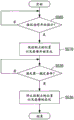
Fig. 7 is a flowchart showing an example of a flow of processing performed by robot control device 30 to operate robot 20 when the operation mode is the second mode.
Fig. 8 is a diagram showing a specific example 1 of the movement execution direction and the predetermined direction under the second predetermined condition. The specific example 1 is an example in which both the movement execution direction and the predetermined direction are translational directions, and the movement execution direction and the predetermined direction are directions different from each other.
Fig. 9 is a diagram showing a specific example 2 of the movement execution direction and the predetermined direction under the second predetermined condition. The specific example 2 is an example in which both the movement execution direction and the predetermined direction are translational directions, and the movement execution direction and the predetermined direction are the same direction.
Fig. 10 is a diagram showing a specific example 3 of the movement execution direction and the predetermined direction under the second predetermined condition. The specific example 3 is an example in which the movement execution direction is a translation direction and the predetermined direction is a rotation direction.
Fig. 11 is a diagram showing a specific example 4 of the movement execution direction and the predetermined direction under the second predetermined condition. The specific example 4 is an example in which both the movement execution direction and the predetermined direction are rotation directions, and the movement execution direction and the predetermined direction are the same direction.
Fig. 12 is a diagram showing a specific example 5 of the movement execution direction and the predetermined direction under the second predetermined condition. The specific example 5 is an example in which both the movement execution direction and the predetermined direction are rotation directions, and the movement execution direction and the predetermined direction are directions different from each other.
Fig. 13 is a diagram showing a specific example 6 of the movement execution direction and the predetermined direction under the second predetermined condition. The specific example 6 is an example in which the movement execution direction is a rotation direction and the predetermined direction is a translation direction.
Fig. 14 is a diagram showing a specific example 1 of the movement execution direction and the predetermined direction when the predetermined direction is the direction corresponding to the portion of the hand H.
Fig. 15 is a diagram showing a specific example 2 of the movement execution direction and the predetermined direction in the case where the predetermined direction corresponds to the portion of the hand H.
Fig. 16 is a flowchart showing an example of a flow of processing performed by the robot controller 30 to operate the robot 20 when the operation mode is the first mode.
Fig. 17 is a diagram showing an example of the positional relationship between the hand H and the table TB before the position and posture of the control point T1 are changed in step S510.
Fig. 18 is a diagram showing an example of the positional relationship between the hand H and the table TB before the change of the position and posture of the control point T1 is stopped in step S530.
Detailed Description
Embodiment
Hereinafter, embodiments of the present invention will be described with reference to the drawings.
Structure of robot System
First, the configuration of the robot system 1 will be described.
Fig. 1 is a diagram showing an example of the configuration of a robot system 1 according to the present embodiment. The robot system 1 includes a robot 20 and a control device 25. The control device 25 is configured by a robot control device 30 and a teaching device 50 that is separate from the robot control device 30. The control device 25 may be integrally formed with the teaching device 50 in addition to the robot control device 30. In this case, the control device 25 has functions of the robot control device 30 and the teaching device 50 described below.
The robot 20 is a single-arm robot having an arm a and a support base B for supporting the arm a. The single-arm robot is a robot having 1 arm (arm) such as arm a in this example. In addition, the robot 20 may be a multi-arm robot, in addition to a single-arm robot. A dobby robot is a robot having two or more arms (for example, two or more arms a). Among the multi-arm robots, a robot having two arms is also called a double-arm robot. That is, the robot 20 may be a two-arm robot having two arms, or may be a multi-arm robot having 3 or more arms (for example, 3 or more arms a). The robot 20 may be another robot such as a SCARA robot or a rectangular robot. The rectangular robot is, for example, a truss type robot.
Arm a includes end effector E, manipulator M, and force detecting unit 21. The end effector E is an end effector having a finger capable of holding an object in this example. The end effector E may be an end effector that can lift an object by suction of air, magnetic force, a clamp, or the like, or another end effector, in addition to the end effector having the finger.
The end effector E is communicably connected to the robot control device 30 through a cable. Thereby, the end effector E performs an operation based on the control signal acquired from the robot control device 30. The wired communication via the cable is performed based on standards such as ethernet (registered trademark) and USB (Universal Serial Bus: universal serial bus). The end effector E may be connected to the robot control device 30 by wireless communication based on a communication standard such as Wi-Fi (registered trademark).
The manipulator M has 7 joints. The 7 joints are each provided with an actuator not shown. That is, the arm a provided with the manipulator M is a 7-axis vertical multi-joint arm. The arm a performs 7-axis degrees of freedom motions by the coordinated motions of the support table B, the end effector E, the manipulator M, and the actuators of the 7 joints included in the manipulator M. The arm a may be configured to operate with a degree of freedom of 6 or less, or may be configured to operate with a degree of freedom of 8 or more.
When the arm a is operated with a degree of freedom of 7 axes, the posture that the arm a can obtain increases as compared with when the arm a is operated with a degree of freedom of 6 axes or less. Thus, for example, the arm a can smoothly perform the operation, and interference with an object existing around the arm a can be easily avoided. In addition, when the arm a is operated with a degree of freedom of 7 axes, the control calculation amount of the arm a becomes smaller and easier to perform than when the arm a is operated with a degree of freedom of 8 axes or more.
The 7 actuators (provided in the joints) included in the manipulator M are connected to be communicable with the robot control device 30 via cables. This causes the actuator to operate the manipulator M based on the control signal acquired from the robot control device 30. And, each actuator is provided with an encoder. Each encoder outputs information indicating the rotation angle of the actuator provided with each encoder to the robot control device 30. The wired communication via the cable is performed based on standards such as ethernet (registered trademark) and USB. Some or all of the 7 actuators included in the manipulator M may be connected to the robot control device 30 by wireless communication based on a communication standard such as Wi-Fi (registered trademark).
The force detection section 21 is provided between the end effector E and the manipulator M. The force detection unit 21 is, for example, a force sensor. The force detecting portion 21 detects an external force applied to the hand H. In this example, the hand H refers to the end effector E or an object held by the end effector E. In this example, the external force refers to both of the force applied to the hand H and the moment applied to the hand H. That is, the force detection unit 21 detects the magnitude of the force applied to the hand H in the direction of each coordinate axis of the force detection coordinate system. The force detecting unit 21 detects the magnitude of the moment applied to the hand H and applied around each coordinate axis. The force detection unit 21 outputs force detection information including force detection values indicating the detected magnitudes to the robot control device 30 by communication. The force detection coordinate system is a three-dimensional local coordinate system that corresponds to the force detection unit 21 so as to move together with the force detection unit 21. The external force may be any one of a force applied to the hand H and a moment applied to the hand H.
The force detection information is used for force control, which is control of the arm a by the robot control device 30 based on the force detection information. The force control means, for example, compliant motion control such as impedance control. The force detection unit 21 may be another sensor that detects an external force applied to the hand H such as a torque sensor.
The force detection unit 21 is communicably connected to the robot control device 30 via a cable. The wired communication via the cable is performed based on standards such as ethernet (registered trademark) and USB. The force detection unit 21 and the robot control device 30 may be connected by wireless communication based on a communication standard such as Wi-Fi (registered trademark).
In this example, the robot control device 30 is a robot controller. The robot control device 30 acquires teaching point information from the teaching device 50. The teaching point information is information indicating teaching points. The teaching point is a virtual point indicating a position and a posture to be a target for changing the position and the posture of the robot 20 when the robot control device 30 causes the robot 20 to perform an operation. The teaching points are associated with teaching point position information, teaching point posture information, and teaching point identification information. The teaching point position information is information indicating the position of the teaching point. The teaching point posture information is information indicating the posture of the teaching point. The teaching point identification information is information identifying a teaching point.
In this example, the position of the teaching point is represented by the position of the origin of the teaching point coordinate system in the robot coordinate system RC, which is a three-dimensional local coordinate system in which the teaching point corresponds to. The posture of the teaching point is expressed by the directions of the coordinate axes of the teaching point coordinate system in the robot coordinate system RC.
The robot control device 30 stores teaching point information acquired from the teaching device 50. The robot control device 30 generates a control signal for operating the robot 20 based on the stored teaching point information. Specifically, the robot control device 30 acquires information indicating the rotation angle of each actuator from an encoder provided for each joint of the manipulator M. The robot control device 30 generates a control signal based on the stored teaching point information and information indicating the acquired rotation angle. The robot control device 30 transmits the generated control signal to the robot 20, and operates the respective actuators to thereby operate the robot 20. Here, the control signal also includes a control signal for controlling the end effector E.
Further, the robot control device 30 acquires various instructions from the teaching device 50. The robot control device 30 switches the operation mode of the robot control device 30 based on an operation mode switching instruction for switching the operation mode of the robot control device 30 among the acquired instructions. Specifically, in this example, robot control device 30 switches the operation mode to any one of the first mode, the second mode, and the third mode based on the operation mode switching instruction. The robot control device 30 causes the robot 20 to execute an operation corresponding to the operation mode after switching. The operation mode switching instruction is an instruction including information indicating any one of the first mode, the second mode, and the third mode. The robot control device 30 may be configured to switch to either the first mode or the second mode, to either the second mode or the third mode, or to either the first mode or the third mode. The robot control device 30 may be configured to switch to any one of a part or all of the 3 modes from the first mode to the third mode and another mode different from the 3 modes.
In this example, the first mode is an automatic action mode. The automatic operation mode is a mode in which the robot 20 is moved until the external force applied to the hand H satisfies a first predetermined condition. That is, the first mode is a mode in which the robot 20 is caused to perform an operation by the force control robot control device 30 until a first predetermined condition is satisfied. The first mode may be other than the automatic operation mode. The first predetermined condition is an example of the predetermined condition. The first predetermined condition will be described later.
In this example, the second mode is a jog mode. The jog operation mode is a mode in which a second portion provided in the robot 20 is moved by a predetermined amount in a predetermined direction based on an external force applied to the first portion provided in the robot 20. Hereinafter, a case where the first portion and the second portion are the same portion and the first portion and the second portion are the hand H will be described as an example. That is, the second mode is a mode in which the hand H is moved by a predetermined amount in a predetermined direction based on an external force applied to the hand H. The first portion may be other portions than the portion of the robot 20. The second portion may be a portion different from the first portion among other portions of the robot 20. The second mode may be other than the jog mode.
In this example, the third mode is a direct action mode. The direct operation mode is a mode in which the hand H is moved in the direction in which the external force is applied by an amount corresponding to the magnitude of the external force based on the external force applied to the hand H provided in the robot 20. That is, the third mode is a mode in which, in the case where the user activates the robot 20 in Direct teaching (Direct teaching), the robot control device 30 causes the robot 20 to perform an operation. The third mode may be a mode other than the direct operation mode. Hereinafter, since the operation of the robot 20 in the third mode is an operation known in the direct teaching, the description of the third mode is omitted.
Further, the robot control device 30 outputs information indicating the current position and posture of the robot 20 to the teaching device 50 based on a position and posture information output instruction to output the information to the teaching device 50, among instructions acquired from the teaching device 50.
The robot control device 30 may be built into the robot 20 instead of being provided outside the robot 20.
In this example, the teaching device 50 is a teaching console. The teaching device 50 outputs various instructions to the robot control device 30 based on an operation received from a user. The teaching device 50 outputs an operation mode switching instruction to the robot control device 30, thereby switching the operation mode of the robot control device 30.
The teaching device 50 outputs a position and orientation information output instruction among instructions output to the robot control device 30, thereby acquiring information indicating the current position and orientation of the robot 20 from the robot control device 30. The teaching device 50 generates teaching point information based on the acquired information. The teaching device 50 outputs the generated teaching point information to the robot control device 30 and stores the teaching point information. That is, teaching device 50 teaches teaching points indicated by the generated teaching point information to robot control device 30.
The teaching device 50 is communicably connected to the robot control device 30 via a cable. The wired communication via the cable is performed based on standards such as ethernet (registered trademark) and USB. The teaching device 50 and the robot control device 30 may be connected by wireless communication based on a communication standard such as Wi-Fi (registered trademark).
The teaching device 50 may be a remote controller or the like having a function of the teaching device 50 and capable of outputting instructions to the robot control device 30, in addition to the teaching console.
Summary of the process of the robot execution operation by the robot controller
Hereinafter, an outline of a process of causing the robot control device 30 to operate the robot 20 will be described.
As shown in fig. 1, in this example, the robot 20 holds the object O1 in advance by the end effector E. That is, the hand H in this example refers to the end effector E or the object O1 held by the end effector E. The object O1 is, for example, an industrial part or component, a product, or the like. The object O1 may be a part or a component of a commodity different from the industrial use, a product, or another object such as a living body. In the example shown in fig. 1, the object O1 is represented as a cube-shaped object. In addition, the shape of the object O1 may be other shapes instead of the cube shape.
The robot control device 30 sets a control point T of a TCP (Tool Center Point: tool center point) that is movable together with the end effector E at a position corresponding to the end effector E in advance. The position corresponding to the end effector E in advance is, for example, a position of the center of gravity of the first object O1 grasped in advance by the end effector E. The position corresponding to the end effector E may be other positions such as the position of the center of gravity of the end effector E, or may be any position corresponding to the manipulator M.
The control point T1 corresponds to control point position information, which is information indicating the position of the control point T1, and control point posture information, which is information indicating the posture of the control point T1. In addition, the control point T1 may be configured to be associated with other information. When the robot control device 30 specifies (determines) the control point position information and the control point posture information, the position and posture of the control point T1 are determined. The position and posture are those of the robot coordinate system RC. The robot control device 30 specifies control point position information and control point posture information. The robot control device 30 operates the arm a so that the position of the control point T1 coincides with the position indicated by the specified control point position information, and so that the posture of the control point T1 coincides with the posture indicated by the specified control posture information. That is, the robot control device 30 specifies the control point position information and the control point posture information to operate the robot 20.
In this example, the position of the control point T1 is represented by the position of the origin of the control point coordinate system TC1 in the robot coordinate system RC. The posture of the control point T1 is represented by the direction of each coordinate axis of the control point coordinate system TC1 in the robot coordinate system RC. The control point coordinate system TC1 is a three-dimensional local coordinate system that corresponds to the control point T1 so as to move together with the control point T1. In this example, the position and posture of the first object O1 are represented by the position and posture of the control point T1. In this example, the directions of the coordinate axes of the control point coordinate system TC1 are identical to the directions of the coordinate axes of the force detection coordinate system. The direction of each coordinate axis of the control point coordinate system TC1 may not coincide with the direction of each coordinate axis of the force detection coordinate system.
The robot control device 30 sets the control point T1 based on control point setting information input in advance by the user. The control point setting information is information indicating, for example, the position and posture of the center of gravity of the end effector E, and the position and posture of the control point T1 relative to each other. The control point setting information may be information indicating any one of a position and a posture corresponding to the end effector E, a position and a posture corresponding to the control point T1, a position and a posture corresponding to the manipulator M, a position and a posture corresponding to the control point T1, or a position and a posture corresponding to other parts of the robot 20.
Hereinafter, a case where the position and posture of the robot 20 are the position and posture of the control point T1 will be described as an example. The position and posture of the robot 20 may be those of other parts that operate together with the operation of the robot 20.
The robot control device 30 operates the robot 20 based on the teaching point information. When the robot 20 is operated based on the teaching point information, the robot control device 30 sequentially specifies 1 or more teaching points indicated by the teaching point information based on an operation program inputted in advance by the user. The robot control device 30 designates, as control point position information, teaching point position information corresponding to a designated teaching point, that is, designated teaching point, and designates, as control point posture information, teaching point posture information corresponding to the designated teaching point. That is, the robot control device 30 specifies control point position information and control point posture information based on the specified teaching point. Thereby, the robot control device 30 can match the control point T1 with the designated teaching point. In this example, the fact that a certain teaching point coincides with the control point T1 means that the position and posture of the teaching point coincides with the position and posture of the control point T1.
In addition, when the operation mode is any one of the first mode to the third mode, the robot control device 30 operates the robot 20 based on the force detection information acquired from the force detection unit 21.
Specifically, the robot control device 30 acquires force detection information from the force detection unit 21. When the operation mode is the first mode, the robot control device 30 changes the position and posture of the control point T1 to a position and posture that achieve a state in which the external force applied to the hand H satisfies the first predetermined condition, based on the acquired force detection information. The robot control device 30 calculates the position and orientation in which the state is achieved based on the force control parameter, the kinetic equation of motion, and the force detection information, which are input to the robot control device 30 in advance.
When the operation mode is the second mode, the robot control device 30 moves the control point T1 by a predetermined amount in a predetermined direction when the external force applied to the hand H satisfies the second predetermined condition based on the force detection information acquired from the force detection unit 21. Thereby, the robot control device 30 moves the hand H by a predetermined amount in a predetermined direction.
When the operation mode is the third mode, the robot control device 30 moves the control point T1 by an amount corresponding to the external force applied to the hand H based on the force detection information acquired from the force detection unit 21. The robot control device 30 calculates an amount corresponding to the external force based on the force control parameter, the kinetic equation of motion, and the force detection information, which are input to the robot control device 30 in advance.
Teaching points taught by the teaching device to the robot control device
The teaching points taught by the robot control device 30 will be described below with respect to the teaching device 50.
As teaching points taught to the robot control device 30, the teaching device 50 teaches the final target teaching point and the standby teaching point. That is, the teaching device 50 generates teaching point information indicating the final target teaching point and the standby teaching point, respectively. The teaching device 50 outputs the generated teaching point information to the robot control device 30 and stores the teaching point information.
In this example, the final target teaching point is a teaching point that coincides with the control point T1 when the robot 20 places the object O1 in the placement area RA set on the upper surface of the table TB. In this example, the table TB is a table such as a work table. The table TB is disposed on the floor so that the upper surface of the table TB is orthogonal to the Z axis of the robot coordinate system RC. The table TB may be any other object as long as it has a bottom surface, a shelf, or the like on which the object O1 can be placed. The upper surface of the table TB may be configured not to be orthogonal to the Z axis of the robot coordinate system RC. The table TB is an example of an object.
In this example, the standby teaching point is a teaching point at which the robot 20 matches the control point T1 and causes the control point T1 to stand by before the object O1 is placed in the placement area RA. The standby teaching point is a teaching point distant from the final target teaching point by a predetermined first distance in the positive direction of the Z axis of the robot coordinate system RC. The first distance is for example 10 cm. The predetermined distance may be a distance shorter than 10 cm or a distance longer than 10 cm as long as the object O1 does not contact the table TB.
The teaching device 50 switches the operation mode of the robot control device 30 based on the operation received from the user. The robot control device 30 whose operation mode is switched by the teaching device 50 causes the robot 20 to execute an operation corresponding to the current operation mode, and causes the position and posture of the control point T1 to coincide with those desired by the user. When the position and posture of the control point T1 are matched with the position and posture desired by the user, the teaching device 50 acquires information indicating the current position and posture of the control point T1 from the robot control device 30. The teaching device 50 generates teaching point information indicating teaching points based on the acquired information. Thereby, the teaching device 50 generates teaching point information indicating the standby teaching point and teaching point information indicating the final target teaching point. The teaching device 50 then outputs the generated teaching point information to the robot control device 30 and stores the teaching point information. That is, teaching device 50 teaches teaching point information to robot control device 30.
The following will describe in detail the process of the teaching device 50 outputting various instructions to the robot control device 30, the process of the robot control device 30 switching the operation mode based on the operation mode switching instruction, the process of the robot control device 30 outputting information indicating the current position and posture of the control point T1 to the teaching device 50 based on the position and posture information output instruction, the process of the robot control device 30 operating the robot 20 when the operation mode is the second mode, and the process of the robot control device 30 operating the robot 20 when the operation mode is the first mode.
Hardware configuration of robot controller and teaching device
The hardware configuration of the robot control device 30 and the teaching device 50 will be described below with reference to fig. 2. Fig. 2 is a diagram showing an example of the hardware configuration of robot control device 30 and teaching device 50. Fig. 2 is a diagram in which the hardware configuration of the robot control device 30 (the functional unit with reference numerals of 30 or more in fig. 2) and the hardware configuration of the teaching device 50 (the functional unit with reference numerals of 50 or more in fig. 2) are simply superimposed.
The robot control device 30 includes, for example, a CPU (Central Processing Unit: central processing unit) 31, a storage unit 32, an input receiving unit 33, a communication unit 34, and a display unit 35. The robot control device 30 performs communication with the robot 20 via the communication unit 34. These components are communicably connected to each other via a Bus (Bus).
The teaching device 50 includes, for example, a CPU51, a storage unit 52, an input receiving unit 53, a communication unit 54, and a display unit 55. The teaching device 50 communicates with the robot control device 30 via the communication unit 54. These components are communicably connected to each other via a Bus (Bus).
The CPU31 executes various programs stored in the storage unit 32.
The storage unit 32 includes, for example, an HDD (Hard Disk Drive), an SSD (Solid State Drive) an EEPROM (Electrically Erasable Programmable Read-Only Memory), a ROM (Read-Only Memory), a RAM (Random Access Memory: random access Memory), and the like. The storage unit 32 may be an external storage device connected by a digital input/output interface such as USB instead of the device built in the robot control device 30. The storage unit 32 stores various programs including various information, images, and operation programs processed by the robot control device 30, and teaching point information.
The input receiving unit 33 is, for example, a touch panel integrally formed with the display unit 35. The input receiving unit 33 may be a keyboard, a mouse, a touch panel, or other input devices.
The communication unit 34 includes, for example, a digital input/output interface such as USB, an ethernet (registered trademark) interface, and the like.
The display unit 35 is, for example, a liquid crystal display panel or an organic EL (Electro Luminescence: electroluminescence) display panel. .
The CPU51 executes various programs stored in the storage unit 52.
The storage unit 52 includes, for example, an HDD or SSD, EEPROM, ROM, RAM. The storage unit 52 may be an external storage device connected by a digital input/output interface such as USB instead of the device built in the teaching device 50. The storage unit 52 stores various information, images, and programs processed by the teaching device 50.
The input receiving unit 53 is, for example, a touch panel integrally formed with the display unit 55. The input receiving unit 53 may be a keyboard, a mouse, a touch panel, or other input devices.
The communication unit 54 includes, for example, a digital input/output interface such as USB, an ethernet (registered trademark) interface, and the like.
The display unit 55 is, for example, a liquid crystal display panel or an organic EL display panel.
Robot controller and teaching device
The functional configurations of the robot controller 30 and the teaching device 50 will be described below with reference to fig. 3. Fig. 3 is a diagram showing an example of the functional configuration of robot control device 30 and teaching device 50.
The robot control device 30 includes a storage unit 32 and a control unit 36.
The control unit 36 controls the entire robot control device 30. The control unit 36 includes a force detection information acquisition unit 361, a storage control unit 363, an information reading unit 364, an operation mode switching unit 365, an information output unit 366, and a robot control unit 367. These functional units included in the control unit 36 are realized by, for example, the CPU31 executing various programs stored in the storage unit 32. Some or all of the functional units may be hardware functional units such as LSIs (Large Scale Integration: large scale integration) and ASICs (Application Specific Integrated Circuit: application specific integrated circuits).
The force detection information acquisition unit 361 acquires force detection information from the force detection unit 21.
The storage control unit 363 stores teaching point information acquired from the teaching device 50 in the storage unit 32.
The information reading section 364 reads various information from the storage section 32.
The operation mode switching unit 365 switches the operation mode of the robot control device 30 to the mode indicated by the operation mode switching instruction based on the operation mode switching instruction among the instructions acquired from the teaching device 50.
The information output unit 366 outputs an instruction based on position and orientation information among instructions acquired from the teaching device 50, and outputs information indicating the current position and orientation of the control point T1 to the teaching device 50.
The robot control unit 367 causes the robot 20 to execute an operation corresponding to the current operation mode of the robot control device 30 based on the force detection information acquired from the force detection unit 21 by the force detection information acquisition unit 361. The robot control unit 367 operates the robot 20 based on the teaching point information stored in the storage unit 32 by the storage control unit 363.
The teaching device 50 includes a storage unit 52, an input receiving unit 53, a display unit 55, and a control unit 56.
The control unit 56 controls the entire teaching device 50. The control unit 56 includes a display control unit 561, an instruction information generating unit 563, and an instruction information output unit 565. These functional units included in the control unit 56 are realized by, for example, the CPU51 executing various programs stored in the storage unit 52. Some or all of the functional units may be hardware functional units such as LSI and ASIC.
The display control unit 561 generates various screens displayed on the display unit 55. The display control unit 561 causes the display unit 55 to display the generated screen.
The instruction information generating unit 563 generates various instructions to be output to the robot control device 30 based on an operation received by the user from the screen displayed on the display control unit 561 by the display unit 55.
The instruction information output unit 565 outputs the instruction generated by the instruction information generation unit 563 to the robot control device 30.
Processing of the teaching device to output various instructions to the robot control device
The process of teaching device 50 outputting various instructions to robot control device 30 will be described below with reference to fig. 4. Fig. 4 is a flowchart showing an example of a flow of processing in which teaching device 50 outputs various instructions to robot control device 30. In the flowchart shown in fig. 4, a description will be given of a case where a main screen for receiving operations for outputting various instructions to the robot control device 30 from a user has been displayed on the display unit 55 by the display control unit 561.
The instruction information generating unit 563 stands by until receiving the user operation on the home screen (step S110). When it is determined that the operation of the user is received on the main screen (step S110—yes), the instruction information generating unit 563 determines whether or not the operation is an operation to switch the operation mode of the robot control device 30 (step S120).
For example, when information indicating any one of the first to third modes is selected by the operation received in step S110, the instruction information generating unit 563 determines that the operation is an operation to switch the operation mode of the robot control device 30. On the other hand, when the information indicating any one of the first to third modes is not selected by the operation received in step S110, the instruction information generating unit 563 determines that the operation is not an operation to switch the operation mode of the robot control device 30.
When it is determined that the operation received in step S110 is an operation to switch the operation mode of the robot control device 30 (step S120—yes), the instruction information generating unit 563 generates an operation mode switching instruction including the information indicating the mode selected in step S110 (step S130). The instruction information output unit 565 outputs the operation mode switching instruction generated by the instruction information generation unit 563 in step S130 to the robot control device 30 (step S140).
On the other hand, when it is determined that the operation received in step S110 is not an operation to switch the operation mode of the robot control device 30 (step S120—no), the instruction information generating unit 563 determines whether or not the operation received in step S110 is an operation to acquire the current position and posture of the robot 20 (in this example, the current position and posture of the control point T1) (step S160). When it is determined that the operation received in step S110 is an operation to acquire information indicating the current position and posture of the control point T1 (step S160—yes), the instruction information generating unit 563 generates a position and posture information output instruction (step S170). The instruction information generating unit 563 outputs the position and orientation information output instruction generated in step S170 to the robot control device 30 (step S180).
On the other hand, when it is determined that the operation received in step S110 is not an operation to acquire the position and posture of the current control point T1 (step S160-no), the instruction information generating unit 563 executes a process corresponding to the operation received in step S110 (step S190). This processing includes processing for generating an instruction other than the operation mode switching instruction and the position and orientation information output instruction, and processing for outputting the generated instruction to the robot control device 30.
After performing any one of the processes of step S140, step S180, and step S190, the instruction information generating unit 563 determines whether or not the reception of the operation from the user on the main screen is ended (step S150). For example, when an operation to delete the home screen is received in the home screen, the instruction information generating unit 563 determines that the reception of the operation from the user in the home screen has ended. On the other hand, when the operation to delete the home screen is not received in the home screen, the instruction information generating unit 563 determines that the reception of the operation from the user in the home screen is not completed.
When it is determined that the reception of the operation from the user on the home screen is not completed (step S150—no), the instruction information generating unit 563 moves to step S110, and stands by until the operation from the user is received again on the home screen. On the other hand, when it is determined that the reception of the operation from the user has ended in the main screen (step S150—yes), the instruction information generating section 563 ends the processing.
Robot control device switching operation mode based on operation mode switching instruction
The following describes a process of switching the operation mode by the robot control device 30 based on the operation mode switching instruction with reference to fig. 5. Fig. 5 is a flowchart showing an example of a flow of processing in which robot control device 30 switches the operation mode based on the operation mode switching instruction.
The operation mode switching unit 365 stands by until an operation mode switching instruction is acquired from the teaching device 50 (step S210). When it is determined that the operation mode switching instruction has been acquired from the teaching device 50 (step S210—yes), the operation mode switching unit 365 switches the current operation mode of the robot control device 30 to the mode indicated by the operation mode switching instruction acquired from the teaching device 50 in step S210 (step S220).
Further, the robot control device 30 may be configured such that, for example, the robot 20 includes an operation mode switching switch, and an operation mode switching instruction output from the operation mode switching switch is acquired by an operation of the operation mode switching switch by a user. In this case, the user can switch the operation mode of the robot control device 30 by operating the operation mode switch. The operation mode switch is provided in a part of the end effector E and the manipulator M, for example.
Based on the position and orientation information output instruction, the robot control device outputs information indicating the position and orientation of the current control point to the teaching device
The following describes processing of the robot control device 30 to output information indicating the current position and orientation of the control point T1 to the teaching device 50 based on the position and orientation information output instruction, with reference to fig. 6. Fig. 6 is a flowchart showing an example of a flow of processing in which robot control device 30 outputs information indicating the current position and orientation of control point T1 to teaching device 50 based on the position and orientation information output instruction.
The information output unit 366 waits until a position and orientation information output instruction is acquired from the teaching device 50 (step S310). When the information output unit 366 determines that the position and orientation information output instruction obtained from the teaching device 50 is issued (step S310—yes), the robot control unit 367 calculates the current position and orientation of the control point T1. Specifically, the robot control unit 367 acquires information indicating the rotation angle of each actuator from an encoder provided for each joint of the manipulator M. The robot control unit 367 calculates the current position and posture of the control point T1 based on the acquired rotation angle and forward kinematics. The information output unit 366 outputs information indicating the position and posture calculated by the robot control unit 367 to the teaching device 50 (step S320).
When the operation mode is the second mode, the robot control device causes the robot to operate
Hereinafter, a process of operating the robot 20 by the robot control device 30 when the operation mode is the second mode will be described with reference to fig. 7 to 15. Fig. 7 is a flowchart showing an example of a flow of processing performed by robot control device 30 to operate robot 20 when the operation mode is the second mode.
The robot control unit 367 stands by until receiving the operation start instruction (step S405). The operation start instruction is an instruction to start the process of operating the robot 20 by the robot control device 30 in the current operation mode. Here, the robot control unit 367 may be configured to receive an operation start instruction from the user on a screen displayed on the display unit 35, which is not shown, based on an operation received from the user, and may be configured to receive an operation start instruction output from the teaching device 50, or may be configured to receive an operation start instruction output from a switch or the like separate from the robot control device 30 and the teaching device 50.
The robot control unit 367 may be configured to receive, as the operation start instruction, an external force that is applied to the hand H and satisfies a predetermined operation start condition. The operation start condition is, for example, that the magnitude of the force applied to the hand H in the predetermined operation start direction is equal to or greater than a predetermined first threshold. In this case, the operation start direction is a direction input in advance by the user to the robot control unit 367, and is a translation direction in which the hand H is translated. The operation start direction is preferably a direction different from the predetermined direction described below, but may be the same direction as the predetermined direction. The first threshold value may be a threshold value inputted by the user to the robot control unit 367 in advance, or may be any threshold value. In addition to the predetermined first threshold value or more for the magnitude of the force applied to the hand H in the predetermined operation start direction, the operation start condition may be a predetermined second threshold value or more for the magnitude of the moment applied to the hand H in the predetermined operation start direction. In this case, the operation start direction is a direction input in advance by the user to the robot control unit 367, and is a rotation direction in which the hand H is rotated. The second threshold value may be a threshold value inputted by the user to the robot control unit 367 in advance, or may be any threshold value. The operation start condition may be other conditions instead of these conditions.
In step S405, when it is determined that the operation start instruction is received (step S405—yes), the robot control unit 367 determines whether or not an external force satisfying the second predetermined condition is applied to the hand H based on the force detection information acquired from the force detection unit 21 by the force detection information acquisition unit 361 (step S410).
When it is determined in step S410 that the external force satisfying the second predetermined condition is applied to the hand H (step S410—yes), the robot control unit 367 moves the control point T1 by a predetermined amount in the predetermined direction (step S420).
The predetermined direction is a direction input by the user to the robot control unit 367 in advance. The predetermined amount is a movement amount input in advance by the user to the robot control unit 367. When the predetermined direction is a translation direction in which the control point T1 is translated, the predetermined amount is a translation movement amount by which the control point T1 is translated, for example, 1 mm. In this case, the predetermined amount may be a translational movement amount shorter than 1 mm or a translational movement amount longer than 1 mm. When the predetermined direction is a rotation direction in which the control point T1 is rotated, the predetermined amount is a rotation angle by which the control point T1 is rotated, for example, 1 degree. In this case, the predetermined amount may be a rotation angle smaller than 1 degree, or a rotation angle larger than 1 degree, in addition to 1 degree. Thus, the predetermined direction is either one or both of the translational direction and the rotational direction.
After the control point T1 is moved by a predetermined amount in the predetermined direction in step S420, the robot control unit 367 determines whether or not an operation end instruction has been received (step S430). The operation end instruction is an instruction to end the process of operating the robot 20 by the robot control device 30. Here, the robot control unit 367 may be configured to receive an operation end instruction from the user on a screen displayed on the display unit 35 by a display control unit, not shown, and may be configured to receive an operation end instruction output from the teaching device 50 based on an operation received from the user, or may be configured to receive an operation end instruction output from a switch or the like separate from the robot control device 30 and the teaching device 50.
The robot control device 30 may be configured to receive, as the operation end instruction, an external force applied to the hand H and satisfying a predetermined operation end condition. The operation end condition is, for example, that the magnitude of the force applied to the hand H in the predetermined operation end direction is equal to or greater than a predetermined third threshold. In this case, the operation end direction is a direction input in advance by the user to the robot control unit 367, and is a panning direction in which the hand H is panned. The operation end direction is preferably a direction different from the predetermined direction, but may be the same direction as the predetermined direction. The third threshold value may be a threshold value inputted by the user to the robot control unit 367 in advance, or may be any threshold value. In addition to the predetermined third threshold value or more for the magnitude of the force applied to the hand H in the predetermined operation end direction, the operation end condition may be a predetermined fourth threshold value or more for the magnitude of the moment applied to the hand H in the predetermined operation end direction. In this case, the operation end direction is a direction input in advance by the user to the robot control unit 367, and is a rotation direction in which the hand H is rotated. The fourth threshold value may be a threshold value inputted by the user to the robot control unit 367 in advance, or may be any threshold value. The operation end condition may be another condition instead of these conditions.
When it is determined in step S430 that the operation end instruction has not been received (step S430—no), the robot control unit 367 moves to step S410 and stands by until the second predetermined condition is satisfied again. On the other hand, when it is determined that the operation end instruction is received (step S430—yes), the robot control unit 367 ends the process.
On the other hand, when it is determined in step S410 that the external force satisfying the second predetermined condition is not applied to the hand H (step S410—no), the robot control unit 367 proceeds to step S430, and determines whether or not an operation end instruction has been received.
In this way, when the robot control device 30 operates the robot 20 in the second mode, the hand H is moved by a predetermined amount in a predetermined direction based on the external force applied to the hand H. Thus, in the second mode, the robot control unit 367 can keep the movement amount of the hand H constant due to the external force applied to the hand H by the user. As a result, the robot control device 30 can change the position and posture of the control point T1 to the desired position and posture with high accuracy by inputting a predetermined amount to the robot control unit 367 by a user, for example.
Further, even in the case where the user continuously applies an external force satisfying the second predetermined condition to the hand H in step S410, the robot control unit 367 in this example executes the process of step S420 only 1 time. That is, even if the user continues to apply an external force satisfying the second predetermined condition to the hand H in step S410, the robot control unit 367 does not move the control point T1 by a predetermined amount that is several times the predetermined amount in the predetermined direction. When the user does not move the control point T1 by a predetermined amount which is a multiple of a predetermined amount in the predetermined direction, the user needs to repeat the operation from the application of the external force satisfying the second predetermined condition to the release of the external force applied to the hand H a predetermined number of times.
In the second mode, the robot 20 is operated, and after the adjustment of the position and posture of the hand H by the user, the robot control device 30 outputs information indicating the current position and posture of the control point T1 to the teaching device 50 through the processing of the flowchart shown in fig. 6. The teaching device 50 generates teaching point information based on the information acquired from the robot control device 30. The teaching device 50 outputs the generated teaching point information to the robot control device 30. The robot control device 30 stores the teaching point information acquired from the teaching device 50. For example, the robot control device 30 stores teaching point information indicating the standby teaching point and the final target teaching point acquired from the teaching device 50, respectively. As a result, in the second mode, the robot control device 30 can control the robot 20 based on the position and posture of the control point T1 stored after the hand H is moved by a predetermined amount in the predetermined direction.
Here, the second predetermined condition is described. The second predetermined condition is, for example, that the magnitude of the force applied to the hand H in the movement execution direction is equal to or greater than a fifth threshold. In this case, the movement execution direction is a direction input in advance by the user to the robot control unit 367, and is a panning direction in which the hand H is panned. The fifth threshold value may be a threshold value input in advance by the user to the robot control unit 367, or may be any threshold value. Fig. 8 to 10 each show a specific example of the movement execution direction under the second predetermined condition in this case and the predetermined direction.
Fig. 8 is a diagram showing a specific example 1 of the movement execution direction and the predetermined direction under the second predetermined condition. The specific example 1 is an example in which both the movement execution direction and the predetermined direction are translational directions, and the movement execution direction and the predetermined direction are directions different from each other. Fig. 8 shows a side view of the hand H when viewed from the negative direction of the X-axis of the control point coordinate system TC1 toward the positive direction.
In fig. 8, the movement execution direction is indicated by a direction A1 indicated by an arrow. In the example shown in fig. 8, the movement execution direction is the positive direction of the Y-axis of the control point coordinate system TC 1. That is, when a force that translates the hand H in the positive direction is applied to the hand H as an external force and the magnitude of the force is equal to or greater than the fifth threshold, the robot control unit 367 moves the control point T1 (i.e., the hand H) by a predetermined amount in a predetermined direction. The movement execution direction may be other panning directions in which the hand H is panned, in addition to the positive direction of the Y-axis among the coordinate axes of the control point coordinate system TC 1. The other panning direction may be a panning direction along any one of the coordinate axes of the control point coordinate system TC1, or may be a panning direction not along any one of the coordinate axes of the control point coordinate system TC 1.
In fig. 8, the predetermined direction is indicated by a direction A2 indicated by an arrow. In the example shown in fig. 8, the predetermined direction is the negative direction of the Z axis of the control point coordinate system TC 1. That is, when a force that translates the hand H in the positive direction of the Y axis of the control point coordinate system TC1 is applied to the hand H as an external force and the magnitude of the force is equal to or greater than the fifth threshold, the robot control unit 367 moves the control point T1 (i.e., the hand H) by a predetermined amount in the negative direction of the Z axis of the control point coordinate system TC 1. In this case, the predetermined amount is a movement amount for translating the control point T1. The predetermined direction may be a negative direction of the Z axis among the coordinate axes of the control point coordinate system TC1, or may be another panning direction in which the control point T1 is panned. The other panning direction may be a panning direction along any one of the coordinate axes of the control point coordinate system TC1, or may be a panning direction not along any one of the coordinate axes of the control point coordinate system TC 1.
Fig. 9 is a diagram showing a specific example 2 of the movement execution direction and the predetermined direction under the second predetermined condition. The specific example 2 is an example in the case where both the movement execution direction and the predetermined direction are translational directions, and the movement execution direction and the predetermined direction are the same direction. Fig. 9 shows a side view of the hand H when viewed from the negative direction of the X axis of the control point coordinate system TC1 toward the positive direction.
In fig. 9, the movement execution direction is indicated by a direction A3 indicated by an arrow. In the example shown in fig. 9, the movement execution direction is the negative direction of the Z axis of the control point coordinate system TC 1. That is, when a force that translates the hand H in the negative direction is applied to the hand H as an external force and the magnitude of the force is equal to or greater than the fifth threshold, the robot control unit 367 moves the control point T1 (i.e., the hand H) by a predetermined amount in a predetermined direction. The movement execution direction may be other panning directions in which the hand H is panned, in addition to the negative direction of the Z axis in the coordinate axes of the control point coordinate system TC 1. The other direction may be a panning direction along any one of the coordinate axes of the control point coordinate system TC1, or may be a panning direction not along any one of the coordinate axes of the control point coordinate system TC 1.
In fig. 9, the predetermined direction is indicated by A4 indicated by an arrow. In the example shown in fig. 9, the predetermined direction is the same direction as the movement execution direction, and is the negative direction of the Z axis of the control point coordinate system TC 1. That is, when a force that translates the hand H in the negative direction of the Z axis of the control point coordinate system TC1 is applied to the hand H as an external force and the magnitude of the force is equal to or greater than the fifth threshold, the robot control unit 367 moves the control point T1 (i.e., the hand H) by a predetermined amount in the negative direction. In this case, the predetermined amount is a movement amount for translating the control point T1. The predetermined direction may be a negative direction of the Z axis among the coordinate axes of the control point coordinate system TC1, or may be another panning direction in which the control point T1 is panned. The other panning direction may be a panning direction along any one of the coordinate axes of the control point coordinate system TC1, or may be a panning direction not along any one of the coordinate axes of the control point coordinate system TC 1.
Fig. 10 is a diagram showing a specific example 3 of the movement execution direction and the predetermined direction under the second predetermined condition. The specific example 3 is an example in the case where the movement execution direction is the translation direction and the predetermined direction is the rotation direction. Fig. 10 is a side view showing the hand H when viewed from the negative direction of the X axis of the control point coordinate system TC1 toward the positive direction.
In fig. 10, the movement execution direction is indicated by a direction A5 indicated by an arrow. In the example shown in fig. 10, the movement execution direction is the positive direction of the Y-axis of the control point coordinate system TC 1. That is, when a force that translates the hand H in the positive direction is applied to the hand H as an external force and the magnitude of the force is equal to or greater than the fifth threshold, the robot control unit 367 moves the control point T1 (i.e., the hand H) by a predetermined amount in a predetermined direction. The movement execution direction may be other translation directions for translating the hand H, in addition to the positive direction of the Y-axis among the coordinate axes of the control point coordinate system TC 1. The other panning direction may be a panning direction along any one of the coordinate axes of the control point coordinate system TC1, or may be a panning direction not along any one of the coordinate axes of the control point coordinate system TC 1.
In fig. 10, the predetermined direction is indicated by a direction A6 indicated by an arrow. In the example shown in fig. 10, when the hand H is viewed from the negative direction toward the positive direction of the X axis of the control point coordinate system TC1, the predetermined direction is the rotation direction in which the hand H is rotated clockwise around the X axis. That is, when a force that translates the hand H in the positive direction of the Y axis of the control point coordinate system TC1 is applied to the hand H as an external force and the magnitude of the force is equal to or greater than the fifth threshold, the robot control unit 367 moves the control point T1 (i.e., the hand H) by a predetermined amount in the rotation direction. In this case, the predetermined amount is a rotation amount (rotation angle) by which the control point T1 is rotated. Alternatively, the predetermined direction may be other rotation directions instead of the rotation direction. The other rotation direction may be a rotation direction around any one of the coordinate axes of the control point coordinate system TC1, or may be a rotation direction around an axis different from any one of the coordinate axes of the control point coordinate system TC 1.
The second predetermined condition may be configured such that, for example, the magnitude of the moment applied to the hand H in the movement execution direction is equal to or greater than a sixth threshold. In this case, the movement execution direction is a direction input in advance by the user to the robot control unit 367, and is a rotation direction in which the hand H is rotated. The sixth threshold value may be a threshold value inputted by the user to the robot control unit 367 in advance, or may be any threshold value. Fig. 11 to 13 each show a specific example of the movement execution direction under the second predetermined condition in this case and the predetermined direction.
Fig. 11 is a diagram showing a specific example 4 of the movement execution direction and the predetermined direction under the second predetermined condition. The specific example 4 is an example in which both the movement execution direction and the predetermined direction are rotation directions, and the movement execution direction and the predetermined direction are the same direction. Fig. 11 is a side view showing a case where the hand H is viewed from the negative direction of the X axis of the control point coordinate system TC1 toward the positive direction.
In fig. 11, the movement execution direction is indicated by a direction A7 indicated by an arrow. In the example shown in fig. 11, when the hand H is viewed from the negative direction toward the positive direction of the X axis of the control point coordinate system TC1, the movement execution direction is a rotation direction in which the hand H is rotated clockwise around the X axis. That is, when a torque is applied to the hand H as an external force to rotate the hand H in the rotation direction and the magnitude of the torque is equal to or greater than the sixth threshold, the robot control unit 367 moves the control point T1 (i.e., the hand H) by a predetermined amount in a predetermined direction. In addition, the movement execution direction may be another rotation direction in which the hand H is rotated instead of the rotation direction. The other rotation direction may be a rotation direction around any one of the coordinate axes of the control point coordinate system TC1, or may be a rotation direction around an axis different from any one of the coordinate axes of the control point coordinate system TC 1.
In fig. 11, the predetermined direction is indicated by a direction A7 indicated by an arrow. In the example shown in fig. 11, when the hand H is viewed from the negative direction toward the positive direction of the X axis of the control point coordinate system TC1, the predetermined direction is the rotation direction in which the hand H is rotated clockwise around the X axis. That is, when a torque is applied to the hand H as an external force to rotate the hand H in the rotation direction and the magnitude of the torque is equal to or greater than the sixth threshold, the robot control unit 367 moves the control point T1 (i.e., the hand H) by a predetermined amount in the rotation direction. In this case, the predetermined amount is a rotation amount (rotation angle) by which the control point T1 is rotated. Alternatively, the predetermined direction may be another rotation direction in which the control point T1 is rotated instead of the rotation direction. The other rotation direction may be a rotation direction around any one of the coordinate axes of the control point coordinate system TC1, or may be a rotation direction around an axis different from any one of the coordinate axes of the control point coordinate system TC 1.
Fig. 12 is a diagram showing a specific example 5 of the movement execution direction and the predetermined direction under the second predetermined condition. The specific example 5 is an example in the case where both the movement execution direction and the predetermined direction are rotational directions, and the movement execution direction and the predetermined direction are different directions from each other. Fig. 12 shows a side view of the hand H when viewed from the negative direction of the X axis of the control point coordinate system TC1 toward the positive direction.
In fig. 12, the movement execution direction is indicated by a direction A9 indicated by an arrow. In the example shown in fig. 12, when the hand H is viewed from the negative direction toward the positive direction of the X axis of the control point coordinate system TC1, the movement execution direction is a rotation direction in which the hand H is rotated clockwise around the X axis. That is, when a torque is applied to the hand H as an external force to rotate the hand H in the rotation direction and the magnitude of the torque is equal to or greater than the sixth threshold, the robot control unit 367 moves the control point T1 (i.e., the hand H) by a predetermined amount in a predetermined direction. In addition, the movement execution direction may be another rotation direction in which the hand H is rotated instead of the rotation direction. The other rotation direction may be a rotation direction around any one of the coordinate axes of the control point coordinate system TC1, or may be a rotation direction around an axis different from any one of the coordinate axes of the control point coordinate system TC 1.
In fig. 12, the predetermined direction is indicated by a direction a10 indicated by an arrow. In the example shown in fig. 12, when the hand H is viewed from the positive direction toward the negative direction of the Y axis of the control point coordinate system TC1, the predetermined direction is the rotation direction in which the hand H is rotated clockwise around the Y axis. That is, when the hand H is viewed from the negative direction of the X axis of the control point coordinate system TC1 toward the positive direction, a moment is applied to the hand H as an external force in a rotation direction that rotates the hand H clockwise around the X axis, and when the magnitude of the moment is equal to or greater than the sixth threshold, the robot control unit 367 moves the control point T1 (i.e., the hand H) by a predetermined amount in the rotation direction that rotates the hand H clockwise around the Y axis when the hand H is viewed from the positive direction of the Y axis of the control point coordinate system TC1 toward the negative direction. In this case, the predetermined amount is a rotation amount (rotation angle) by which the control point T1 is rotated. Alternatively, the predetermined direction may be another rotation direction in which the control point T1 is rotated instead of the rotation direction. The other rotation direction may be a rotation direction around any one of the coordinate axes of the control point coordinate system TC1, or may be a rotation direction around an axis different from any one of the coordinate axes of the control point coordinate system TC 1.
Fig. 13 is a diagram showing a specific example 6 of the movement execution direction and the predetermined direction under the second predetermined condition. The specific example 6 is an example in the case where the movement execution direction is the rotation direction and the predetermined direction is the translation direction. Fig. 13 is a side view showing a case where the hand H is viewed from the negative direction of the X axis of the control point coordinate system TC1 toward the positive direction.
In fig. 13, the movement execution direction is indicated by a direction a11 indicated by an arrow. In the example shown in fig. 13, when the hand H is viewed from the negative direction toward the positive direction of the X axis of the control point coordinate system TC1, the movement execution direction is a rotation direction in which the hand H is rotated clockwise around the X axis. That is, when a torque is applied to the hand H as an external force to rotate the hand H in the rotation direction and the magnitude of the torque is equal to or greater than the sixth threshold, the robot control unit 367 moves the control point T1 (i.e., the hand H) by a predetermined amount in a predetermined direction. In addition, the movement execution direction may be another rotation direction in which the hand H is rotated instead of the rotation direction. The other rotation direction may be a rotation direction around any one of the coordinate axes of the control point coordinate system TC1, or may be a rotation direction around an axis different from any one of the coordinate axes of the control point coordinate system TC 1.
In fig. 13, the predetermined direction is indicated by a direction a12 indicated by an arrow. In the example shown in fig. 13, the predetermined direction is the negative direction of the Z axis of the control point coordinate system TC 1. That is, when the hand H is viewed from the negative direction of the X axis of the control point coordinate system TC1 toward the positive direction, a moment in the rotation direction for rotating the hand H clockwise around the X axis is applied to the hand H as an external force, and when the magnitude of the moment is equal to or greater than the sixth threshold, the robot control unit 367 moves the control point T1 (i.e., the hand H) by a predetermined amount in the negative direction of the Z axis of the control point coordinate system TC 1. In this case, the predetermined amount is a movement amount for translating the control point T1. The predetermined direction may be a negative direction of the Z axis among the coordinate axes of the control point coordinate system TC1, or may be another panning direction in which the control point T1 is panned. The other panning direction may be a panning direction along any one of the coordinate axes of the control point coordinate system TC1, or may be a panning direction not along any one of the coordinate axes of the control point coordinate system TC 1.
In the second mode, for example, when the magnitude of the force applied to the hand H in the movement execution direction is equal to or greater than a fifth threshold, the robot control unit 367 may be configured to move the control point T1 by a predetermined amount in the predetermined direction, and when the force is equal to or greater than a seventh threshold, which is a threshold greater than the fifth threshold, the control point T1 may be moved by a second predetermined amount, which is an amount different from the predetermined amount, in a second predetermined direction, which is a direction different from the predetermined direction. That is, the robot control unit 367 may be configured to move the control point T1 by an amount corresponding to the difference in the magnitude of the stage (dispersion) of the force applied to the hand H, in the direction corresponding to the difference.
The robot control unit 367 may be configured to change (move) the rotation angle of the actuator provided in the predetermined joint by a predetermined amount in a predetermined direction when the external force applied to the hand H satisfies the second predetermined condition. When the rotation angle of the actuator is changed by a predetermined amount in a predetermined direction, the predetermined direction is the rotation direction of the actuator, and the predetermined amount is the rotation angle of the actuator.
Further, the robot control unit 367 may be configured to move the rotation angle of the actuator or the control point T1 provided in a predetermined joint by a predetermined amount in a predetermined direction based on an external force applied to any one of the joints when the force detection unit 21 is a torque sensor provided in each joint of the manipulator M. When the rotation angle of the actuator is moved by a predetermined amount in a predetermined direction, the predetermined direction is the rotation direction of the actuator, and the predetermined amount is the rotation angle of the actuator.
The robot control unit 367 may be configured to determine that the external force applied to the hand H satisfies the second predetermined condition when the external force applied to the hand H satisfies the second predetermined condition in step S410 or more, or may be configured to determine that the external force applied to the hand H satisfies the second predetermined condition when the external force applied to the hand H satisfies the second predetermined condition at least once.
In the case where the operation mode is the second mode, the robot control device causes the robot to operate in the modified example of the process of the robot operation >
The predetermined direction described above may be a direction corresponding to a portion of the hand H. The portion refers to a portion to which an external force is applied. That is, the robot control unit 367 moves the hand H by a predetermined amount in a direction corresponding to a portion of the hand H to which the external force is applied, based on the external force applied to the hand H. Thereby, the robot control unit 367 can easily change the direction in which the hand H is moved by the user.
Here, a specific example of the movement execution direction and the predetermined direction when the predetermined direction is the direction corresponding to the portion of the hand H will be described with reference to fig. 14 and 15. In the specific examples described below, the case where the second predetermined condition is that the magnitude of the force applied to the hand H in the movement execution direction is equal to or greater than the fifth threshold will be described as an example. In addition, as in the case of the specific example described above, the second predetermined condition may be that the magnitude of the moment applied to the hand H in the movement execution direction is equal to or greater than a sixth threshold.
Fig. 14 is a diagram showing a specific example 1 of the movement execution direction and the predetermined direction when the predetermined direction is the direction corresponding to the portion of the hand H. The specific example 1 is an example in which an external force is applied to an upper portion, which is a portion on the positive direction side of the Z axis of the control point coordinate system TC1, from the Y axis of the control point coordinate system TC1, among the portions of the hand H. Fig. 14 is a side view showing the hand H when viewed from the negative direction of the X axis of the control point coordinate system TC1 toward the positive direction.
In fig. 14, the movement execution direction is indicated by a direction a13 indicated by an arrow. In fig. 14, the portion to which the force F1 is applied to the hand H is indicated by an arrow. In the example shown in fig. 14, the movement execution direction is the positive direction of the Y-axis of the control point coordinate system TC 1. In this example, an external force is applied to the upper portion of the hand H. That is, when the force F1 that translates the hand H in the positive direction is applied to the hand H as an external force and the magnitude of the force is equal to or greater than the fifth threshold, the robot control unit 367 moves the control point T1 (i.e., the hand H) by a predetermined amount in a predetermined direction corresponding to the upper portion of the hand H. The movement execution direction may be another translation direction for translating the hand H instead of the positive direction of the Y-axis in the coordinate axes of the control point coordinate system TC 1. The other panning direction may be a panning direction along any one of the coordinate axes of the control point coordinate system TC1, or may be a panning direction not along any one of the coordinate axes of the control point coordinate system TC 1.
In fig. 14, the predetermined direction is indicated by a direction a14 indicated by an arrow. In the example shown in fig. 14, the predetermined direction corresponding to the upper portion of the hand H is the positive direction of the Z axis of the control point coordinate system TC 1. That is, when a force for translating the hand H in the positive direction of the Y axis of the control point coordinate system TC1 is applied to the upper portion of the hand H as an external force and the magnitude of the force is equal to or greater than the fifth threshold, the robot control unit 367 moves the control point T1 (i.e., the hand H) by a predetermined amount in the positive direction of the Z axis of the control point coordinate system TC 1. In this case, the predetermined amount is a movement amount for translating the control point T1. The predetermined direction may be other panning directions in which the control point T1 is panned, in addition to the positive direction of the Z-axis among the coordinate axes of the control point coordinate system TC 1. The other panning direction may be a panning direction along any one of the coordinate axes of the control point coordinate system TC1, or may be a panning direction not along any one of the coordinate axes of the control point coordinate system TC 1. The predetermined direction may be a rotation direction instead of the translation direction.
Fig. 15 is a diagram showing a specific example 2 of the movement execution direction and the predetermined direction in the case where the predetermined direction is the direction corresponding to the portion of the hand H. The specific example 2 is an example in which an external force is applied to a lower portion, which is a portion on the negative direction side of the Z axis of the control point coordinate system TC1, from the Y axis of the control point coordinate system TC1 in the portion of the hand H. Fig. 15 shows a side view of the hand H when viewed from the negative direction of the X axis of the control point coordinate system TC1 toward the positive direction.
In fig. 15, the movement execution direction is indicated by a direction a15 indicated by an arrow. In fig. 15, the portion to which the force F2 is applied to the hand H is indicated by an arrow. In the example shown in fig. 15, the movement execution direction is the positive direction of the Y-axis of the control point coordinate system TC 1. In this example, an external force is applied to the lower portion of the hand H. That is, when the force F2 that translates the hand H in the positive direction is applied to the hand H as an external force and the magnitude of the force is equal to or greater than the fifth threshold, the robot control unit 367 moves the control point T1 (i.e., the hand H) by a predetermined amount in a predetermined direction corresponding to the lower portion of the hand H. The movement execution direction may be other translation directions for translating the hand H, in addition to the positive direction of the Y-axis among the coordinate axes of the control point coordinate system TC 1. The other panning direction may be a panning direction along any one of the coordinate axes of the control point coordinate system TC1, or may be a panning direction not along any one of the coordinate axes of the control point coordinate system TC 1.
In fig. 15, the predetermined direction is indicated by a direction a16 indicated by an arrow. In the example shown in fig. 15, the predetermined direction corresponding to the lower portion of the hand H is the negative direction of the Z axis of the control point coordinate system TC 1. That is, when a force that translates the hand H in the positive direction of the Y axis of the control point coordinate system TC1 is applied to the lower portion of the hand H as an external force and the magnitude of the force is equal to or greater than the fifth threshold, the robot control unit 367 moves the control point T1 (i.e., the hand H) by a predetermined amount in the negative direction of the Z axis of the control point coordinate system TC 1. In this case, the predetermined amount is a movement amount for translating the control point T1. The predetermined direction may be a negative direction of the Z axis among the coordinate axes of the control point coordinate system TC1, or may be another panning direction in which the control point T1 is panned. The other panning direction may be a panning direction along any one of the coordinate axes of the control point coordinate system TC1, or may be a panning direction not along any one of the coordinate axes of the control point coordinate system TC 1. The predetermined direction may be a rotation direction instead of the translation direction.
In this way, the robot control unit 367 moves the hand H by a predetermined amount in a direction corresponding to the portion to which the external force is applied, of the portion of the hand H, based on the external force applied to the hand H. Thereby, the robot control unit 367 can easily change the direction in which the hand H is moved by the user.
When the operation mode is the first mode, the robot control device causes the robot to operate
Hereinafter, a process of operating the robot 20 by the robot control device 30 when the operation mode is the first mode will be described with reference to fig. 16 to 18.
Fig. 16 is a flowchart showing an example of a flow of processing performed by the robot controller 30 to operate the robot 20 when the operation mode is the first mode. In the flowchart shown in fig. 16, a case where the control point T1 coincides with the standby teaching point will be described. For example, in the second mode or the third mode, the robot control device 30 can match the control point T1 with the standby teaching point based on an external force applied to the hand H by the user. The following describes a case where the operation mode of the robot control device 30 has been switched to the first mode.
The robot control unit 367 stands by until receiving the operation start instruction (step S505). Here, the robot control unit 367 may be configured to receive an operation start instruction from the user on a screen displayed on the display unit 35, which is not shown, based on an operation received from the user, and may be configured to receive an operation start instruction output from the teaching device 50, or may be configured to receive an operation start instruction output from a switch or the like separate from the robot control device 30 and the teaching device 50. The robot control unit 367 may be configured to receive, as the operation start instruction, an external force that is applied to the hand H and satisfies a predetermined operation start condition.
When it is determined in step S505 that the operation start instruction is received (step S505—yes), the robot control unit 367 starts to change the position and posture of the control point T1 to a position and posture at which the external force applied to the hand H satisfies the first predetermined condition, based on the force detection information acquired by the force detection information acquisition unit 361 from the force detection unit 21 (step S510). Specifically, the robot control unit 367 calculates the position and posture in which the state is achieved based on the force control parameter, the kinetic equation of motion, and the force detection information, which are input to the robot control unit 367 in advance. The robot control unit 367 then starts to change the position and posture of the control point T1 to the calculated position and posture.
In this example, the first predetermined condition means that 3 conditions 1) to 3) shown below are satisfied. The first predetermined condition may be a configuration satisfying some or all of the 3 conditions, or may be a configuration satisfying other conditions, in addition to the configuration satisfying the 3 conditions.
1) The magnitude of the force applied to the hand H in the positive direction of the Z axis of the control point coordinate system TC1 is equal to or greater than a predetermined value.
2) The magnitude of the force applied to the hand H in the X-axis direction and the Y-axis direction of the control point coordinate system TC1 is 0[N.
3) The magnitude of each coordinate axis around the control point coordinate system TC1 among the moments applied to the hand H is 0[N ·m.
The condition 1) above may be that the magnitude of the force applied to the hand H in the negative direction of the Z axis of the control point coordinate system TC1 is equal to or greater than a predetermined value, that the magnitude of the force applied to the hand H in the positive or negative direction of the X axis of the control point coordinate system TC1 is equal to or greater than a predetermined value, or that the magnitude of the force applied to the hand H in the positive or negative direction of the Y axis of the control point coordinate system TC1 is equal to or greater than a predetermined value. Also, in this example, the positive direction of the Z-axis of the control point coordinate system TC1 is a translational direction, and is one example of the first direction. The rotation direction around each coordinate axis of the control point coordinate system TC1 is an example of the second direction.
When the first predetermined condition is that the 3 conditions 1) to 3) are satisfied, the robot control unit 367 keeps the posture of the control point T1 and moves the position of the control point T1 in the positive direction of the Z axis of the control point coordinate system TC 1. The process of step S510 will be described with reference to fig. 17. Fig. 17 is an example diagram showing the positional relationship between the hand H and the table TB before the position and posture of the control point T1 are changed in step S510. Fig. 17 shows a side view of the hand H when viewed from the negative direction of the X axis of the control point coordinate system TC1 toward the positive direction. As shown in fig. 17, at this time point, the control point T1 coincides with the standby teaching point P1. In fig. 17, the arrangement region RA is indicated by a thick line because it is difficult to distinguish the range of the arrangement region RA in a side view.
In the example shown in fig. 17, the hand H is not applied with an external force at this time. That is, since the moment applied to the hand H at this time has satisfied the condition 3) described above, the robot control section 367 maintains the posture of the control point T1 in step S510. Further, since the forces applied to the X-axis direction and the Y-axis direction of the control point coordinate system TC1 among the forces applied to the hand H at this time have already satisfied the condition of 2) described above, the robot control unit 367 holds the positions of the control point T1 in the X-axis direction and the Y-axis direction in step S510. Further, since the force applied to the positive direction of the Z axis of the control point coordinate system TC1 among the forces applied to the hand H at this time does not satisfy the condition 1) described above, the robot control unit 367 starts moving the hand H in the direction opposite to the positive direction so that the positive direction force is applied to the hand H in step S510. In fig. 17, the positive direction is indicated by a direction a17 indicated by an arrow.
After starting the change of the position and posture of the control point T1 in step S510, the robot control unit 367 continues the movement of the control point T1 started in step S510 until the first predetermined condition is satisfied, based on the force detection information acquired by the force detection information acquisition unit 361 from the force detection unit 21 (step S520). When it is determined that the first predetermined condition is satisfied (step S520—yes), the robot control unit 367 determines that the position and posture of the control point T1 match the position and posture desired by the user, and stops the change in the position and posture of the control point T1 (step S530).
The process of step S530 will be described with reference to fig. 18. Fig. 18 is a diagram showing an example of the positional relationship between the hand H and the table TB before the position and posture of the stop control point T1 are changed in step S530. Fig. 18 shows a side view of the hand H when viewed from the negative direction of the X axis of the control point coordinate system TC1 toward the positive direction. In fig. 18, the arrangement region RA is indicated by a thick line because it is difficult to distinguish the range of the arrangement region RA in a side view. In the example shown in fig. 18, the hand H is applied with vertical force from the table TB as an external force at this time. When the vertical resistance is equal to or greater than the predetermined value due to the change in the position and posture of the control point T1 started in step S510, the external force applied to the hand H at that time satisfies the first predetermined condition, and therefore the robot control unit 367 stops the change in the position and posture of the control point T1.
In this way, when the robot control device 30 operates the robot 20 in the first mode, the position and posture of the control point T1 are changed to the position and posture where the external force applied to the hand H satisfies the first predetermined condition. As a result, in the first mode, the robot control unit 367 can change the position and posture of the robot 20 to the desired position and posture corresponding to the table TB with high accuracy without applying an external force to the hand H by the user. As a result, for example, when a condition desired by the user is input to the robot control unit 367 as a first predetermined condition, the robot control device 30 can accurately adjust the position and posture of the hand H.
In the first mode, the robot 20 is operated, and after the user adjusts the position and posture of the hand H, the robot control device 30 outputs information indicating the current position and posture of the control point T1 to the teaching device 50 by the processing of the flowchart shown in fig. 6. The teaching device 50 generates teaching point information based on the information acquired from the robot control device 30. The teaching device 50 outputs the generated teaching point information to the robot control device 30. The robot control device 30 stores the teaching point information acquired from the teaching device 50. For example, robot control device 30 stores teaching point information indicating the final target teaching point acquired from teaching device 50. As a result, in the first mode, the robot control device 30 can operate the robot 20 based on the position and posture of the control point T1 stored when the first predetermined condition is satisfied.
< fine tuning by first and second modes >)
As described above, when the robot 20 is operated in the first mode and the second mode, the robot control device 30 can accurately adjust the position and posture of the hand H. That is, the robot control device 30 can finely adjust the position and posture of the hand H.
Such fine tuning is performed, for example, in direct teaching. In the direct teaching, the robot control device 30 operates the robot 20 in the third mode. Therefore, the user applies an external force to the hand H to change the position and posture of the hand H. However, it is difficult for the user to apply the external force desired by the user to the hand H with good accuracy. Therefore, after the user moves the robot 20 in the third mode by the robot control device 30 to bring the position and posture of the hand H closer to the position and posture desired by the user, the robot 20 is moved by the robot control device 30 in either or both of the first mode and the second mode. That is, in the direct teaching of the position and posture of the stored hand H, the robot control device 30 teaches by either or both of the first mode in which the robot 20 is moved and the second mode in which the robot 20 is operated based on the external force applied to the hand H until the external force applied to the hand H satisfies the first predetermined condition. Thus, the robot control device 30 can accurately match the position and posture of the hand H with the position and posture desired by the user.
Further, such fine adjustment may be performed in the following teaching instead of the direct teaching: when the user operates the jog key, the robot control device 30 causes the robot 20 to operate, and causes the robot control device 30 to store an Online teaching (teaching) of the position and posture of the hand H and a teaching based on a method developed in the future.
As described above, when the position and posture of the robot (in this example, the robot 20) are stored, the control device 25 switches between the first mode in which the robot is moved until the external force applied to the hand (in this example, the hand H) satisfies the predetermined condition (in this example, the first predetermined condition) and the second mode in which the robot is moved based on the external force applied to the first portion (in this example, the hand H) provided in the robot. In this way, the control device 25 can change the position and posture of the robot to a desired position and posture with high accuracy in either the first mode or the second mode.
In the first mode, the control device 25 brings the hand closer to the object (in this example, the table TB) until a predetermined condition is satisfied by control based on the output of the force detection unit (in this example, the force detection unit 21). In this way, in the first mode, the control device 25 can change the position and posture of the robot to a desired position and posture corresponding to the object with high accuracy without applying an external force to the hand by the user.
In the first mode, the control device 25 moves the robot until at least an external force directed in the first direction among external forces applied to the hand is greater than 0, and at least an external force directed in a second direction (in this example, a rotational direction around each coordinate axis of the control point coordinate system TC 1) different from the first direction (in this example, a positive direction of the Z axis of the control point coordinate system TC 1) among the external forces applied to the hand is 0. In this way, in the first mode, the control device 25 can maintain the posture of the robot and move the position of the robot in the direction opposite to the first direction.
In the first mode, the control device 25 moves the robot until at least the force in the first direction, which is the translational direction, among the forces applied to the hand is greater than 0, and the moment in the second direction, which is the rotational direction, is 0. In this way, in the first mode, the control device 25 can maintain the posture of the robot and move the position of the robot in the direction opposite to the first direction, which is the translational direction.
In the first mode, when a predetermined condition is satisfied, the control device 25 stores the current position and posture of the robot (in this example, the position and posture of the control point T1). In this way, in the first mode, the control device 25 can operate the robot based on the position and orientation of the robot stored when the predetermined condition is satisfied.
In the second mode, the control device 25 moves the second part (in this example, the hand H) of the robot by a predetermined amount in a predetermined direction based on an external force applied to the first part (in this example, the hand H) of the robot. In this way, in the second mode, the control device 25 can change the position and posture of the robot to a desired position and posture with high accuracy based on the external force applied to the first portion by the user.
Further, the control device 25 moves the second portion in a predetermined direction and then stores the current position and posture of the robot. In this way, in the second mode, the control device 25 can control the robot based on the position and posture of the robot stored after the second portion is moved by the predetermined amount in the predetermined direction.
The control device 25 moves the second portion by a predetermined amount in either one or both of the translational direction and the rotational direction, and then stores the current position and posture of the hand. In this way, in the second mode, the control device 25 can control the robot based on the stored position and posture after moving the second portion by a predetermined amount in either one or both of the translational direction and the rotational direction.
The control device 25 moves the second part by a predetermined amount in a direction corresponding to a part (in this example, the upper part or the lower part) of the first part to which the external force is applied, according to the external force applied to the first part provided to the robot. Thereby, the control device 25 can easily change the direction in which the second portion is moved by the user.
Although the embodiments of the present invention have been described in detail with reference to the drawings, the specific configuration is not limited to the embodiments, and changes, substitutions, deletions, etc. may be made without departing from the gist of the present invention.
Further, a program for realizing the functions of any of the components of the above-described devices (for example, the control device 25, the robot control device 30, and the teaching device 50) may be recorded on a recording medium readable by a computer, and the program may be read into the computer system and executed. The term "computer System" as used herein refers to a hardware device including an OS (Operating System), a peripheral device, and the like. The "computer-readable recording medium" refers to a portable medium such as a floppy Disk, a magneto-optical Disk, a ROM, or a CD (Compact Disk) -ROM, and a storage device such as a hard Disk incorporated in a computer system. Further, "computer-readable recording medium" refers to a device that holds a program for a constant time, such as a volatile memory (RAM) in a computer system, which becomes a server or a client, in the case where the program is transmitted via a network such as the internet or a communication line such as a telephone line.
The program may be transferred from a computer system storing the program in a storage device or the like to another computer system via a transmission medium or by a transmission wave in the transmission medium. Here, the "transmission medium" for transmitting the program refers to a medium having a function of transmitting information, such as a network (communication network) such as the internet or a communication line (communication line) such as a telephone line.
The program may be a program for realizing a part of the functions described above. The program may be a so-called differential file (differential program) that realizes the functions described above by a combination with a program already recorded in the computer system.
Reference numerals illustrate:
1 … robotic system; 20 … robot; 21 … force detecting section; 30 … robot control device; 31. 51 … CPU; 32. 52 … store; 33. 53 … input receiving section; 34. 54 … communication part; 35. 55 … display part; 36. 56 … control part; 361 and … force detection information acquisition unit; 363 …;364 … information reading section; 365 … operation mode switching unit; 366 … information output unit; 367- … robot control unit; 561 and … display control unit; 563- … instruction information generating unit; 565 and … indicate an information output unit.
Claims (13)
1. A robot system, characterized in that,
the robot system includes:
a robot including a first part, a second part, and a force detection part for detecting an external force; and
and a control device that switches between a mode in which the first portion or the second portion is moved by a predetermined amount in a predetermined direction when the external force is applied to the first portion and a mode in which the first portion or the second portion is moved by an amount corresponding to the magnitude of the external force in the direction in which the external force is applied to the first portion, and operates the robot.
2. A robot system, characterized in that,
the robot system includes:
a robot including a first part, a second part, and a force detection part for detecting an external force; and
and a control device that causes the robot to operate such that the first portion or the second portion is moved by a predetermined amount in a predetermined direction when the external force is applied to the first portion, and that the first portion or the second portion is moved by an amount that is an integer multiple of the predetermined amount in the predetermined direction when a work from applying the external force to the first portion to releasing the external force applied to the first portion is repeated a predetermined number of times.
3. A robot system, characterized in that,
the robot system includes:
a robot including a first part, a second part, and a force detection part for detecting an external force; and
and a control device that switches between a first mode in which the robot is activated until the external force detected by the force detection unit satisfies a predetermined condition and a second mode in which the first portion or the second portion of the robot is activated by a predetermined amount in a predetermined direction that is input in advance based on the external force, and operates the robot.
4. The robot system according to claim 2 or 3, wherein,
the direction of the external force applied to the first portion is a rotation direction, and the predetermined direction is a rotation direction.
5. The robot system according to claim 2 or 3, wherein,
the direction of the external force applied to the first portion is a translational direction, and the predetermined direction is a rotational direction.
6. The robot system according to claim 2 or 3, wherein,
the direction of the external force applied to the first portion is a translational direction, and the prescribed direction is a translational direction.
7. The robot system according to claim 2 or 3, wherein,
the direction of the external force applied to the first portion is a direction different from the predetermined direction.
8. The robot system according to claim 2 or 3, wherein,
the direction of the external force applied to the first portion is the same direction as the predetermined direction.
9. The robot system according to claim 1 to 3, characterized in that,
after the first portion or the second portion is moved by the predetermined amount in the predetermined direction, the current position and orientation are stored.
10. The robot system according to claim 1 to 3, characterized in that,
the predetermined direction is a direction corresponding to a portion of the first portion,
the first portion or the second portion is moved by the predetermined amount in a direction corresponding to a portion of the first portion to which the external force is applied, according to the external force applied to the first portion.
11. A method for controlling a robot, wherein the robot includes a first part, a second part, and a force detecting part for detecting an external force,
The robot is operated by switching between a mode in which the first portion or the second portion is moved by a predetermined amount in a predetermined direction when the external force is applied to the first portion and a mode in which the first portion or the second portion is moved by an amount corresponding to the magnitude of the external force in the direction in which the external force is applied to the first portion.
12. A method for controlling a robot, wherein the robot includes a first part, a second part, and a force detecting part for detecting an external force,
when the external force is applied to the first portion, the first portion or the second portion is moved by a predetermined amount in a predetermined direction,
when the operation from the application of the external force to the first portion to the release of the external force applied to the first portion is repeated a predetermined number of times, the first portion or the second portion is moved by an amount that is an integer multiple of the predetermined amount in the predetermined direction.
13. A method for controlling a robot, wherein the robot includes a first part, a second part, and a force detecting part for detecting an external force,
The robot is operated by switching between a first mode in which the robot is operated until the external force detected by the force detecting unit satisfies a predetermined condition and a second mode in which the first portion or the second portion of the robot is operated by a predetermined amount inputted in advance in a predetermined direction based on the external force.
Applications Claiming Priority (3)
| Application Number | Priority Date | Filing Date | Title |
|---|---|---|---|
| JP2016-054959 | 2016-03-18 | ||
| JP2016054959A JP6733239B2 (en) | 2016-03-18 | 2016-03-18 | Controller and robot system |
| CN201710156754.XA CN107414842B (en) | 2016-03-18 | 2017-03-16 | Control device, robot, and robot system |
Related Parent Applications (1)
| Application Number | Title | Priority Date | Filing Date |
|---|---|---|---|
| CN201710156754.XA Division CN107414842B (en) | 2016-03-18 | 2017-03-16 | Control device, robot, and robot system |
Publications (1)
| Publication Number | Publication Date |
|---|---|
| CN116141290A true CN116141290A (en) | 2023-05-23 |
Family
ID=59847361
Family Applications (2)
| Application Number | Title | Priority Date | Filing Date |
|---|---|---|---|
| CN201710156754.XA Active CN107414842B (en) | 2016-03-18 | 2017-03-16 | Control device, robot, and robot system |
| CN202211704841.1A Pending CN116141290A (en) | 2016-03-18 | 2017-03-16 | Robot system and control method for robot |
Family Applications Before (1)
| Application Number | Title | Priority Date | Filing Date |
|---|---|---|---|
| CN201710156754.XA Active CN107414842B (en) | 2016-03-18 | 2017-03-16 | Control device, robot, and robot system |
Country Status (3)
| Country | Link |
|---|---|
| US (2) | US10350768B2 (en) |
| JP (1) | JP6733239B2 (en) |
| CN (2) | CN107414842B (en) |
Families Citing this family (17)
| Publication number | Priority date | Publication date | Assignee | Title |
|---|---|---|---|---|
| US11093590B2 (en) * | 2015-08-31 | 2021-08-17 | Avaya Inc. | Selection of robot operation mode from determined compliance with a security criteria |
| JP6733239B2 (en) * | 2016-03-18 | 2020-07-29 | セイコーエプソン株式会社 | Controller and robot system |
| JP6870433B2 (en) * | 2017-03-31 | 2021-05-12 | セイコーエプソン株式会社 | Control device and robot system |
| JP2018171668A (en) | 2017-03-31 | 2018-11-08 | セイコーエプソン株式会社 | Control device, robot, and robot system |
| JP6690626B2 (en) * | 2017-10-31 | 2020-04-28 | 株式会社安川電機 | Robot system and robot evacuation method |
| JP7042594B2 (en) * | 2017-11-27 | 2022-03-28 | アズビル株式会社 | Actuator operation switching device |
| JP7135437B2 (en) | 2018-05-22 | 2022-09-13 | セイコーエプソン株式会社 | ROBOT SYSTEM CONTROL METHOD AND ROBOT SYSTEM |
| JP7124439B2 (en) * | 2018-05-22 | 2022-08-24 | セイコーエプソン株式会社 | Control device and robot system |
| JP7131087B2 (en) | 2018-05-31 | 2022-09-06 | セイコーエプソン株式会社 | ROBOT SYSTEM CONTROL METHOD AND ROBOT SYSTEM |
| JP2020001099A (en) | 2018-06-25 | 2020-01-09 | セイコーエプソン株式会社 | Control device, robot and robot system |
| JP7211007B2 (en) * | 2018-10-30 | 2023-01-24 | セイコーエプソン株式会社 | Control device, robot system and control method |
| JP7053443B2 (en) * | 2018-12-07 | 2022-04-12 | ファナック株式会社 | Control device for robots that perform manual operations with the operating device |
| JP7207010B2 (en) * | 2019-02-27 | 2023-01-18 | セイコーエプソン株式会社 | Robot system and its control method |
| JP2021062436A (en) * | 2019-10-11 | 2021-04-22 | セイコーエプソン株式会社 | Teaching method |
| JP2021062443A (en) * | 2019-10-11 | 2021-04-22 | セイコーエプソン株式会社 | Teaching method |
| JP7415447B2 (en) * | 2019-10-31 | 2024-01-17 | セイコーエプソン株式会社 | robot system |
| JP2021160048A (en) * | 2020-04-01 | 2021-10-11 | アズビル株式会社 | Teaching device |
Family Cites Families (67)
| Publication number | Priority date | Publication date | Assignee | Title |
|---|---|---|---|---|
| JPS60252911A (en) * | 1984-05-30 | 1985-12-13 | Hitachi Ltd | Robot containing operation key at its mobile part |
| JPH0741565B2 (en) * | 1986-12-23 | 1995-05-10 | キヤノン株式会社 | Robot teaching method |
| JP2669075B2 (en) | 1989-10-06 | 1997-10-27 | 日立建機株式会社 | Direct teaching device and position teaching method for robot position and posture |
| JPH0440506A (en) * | 1990-06-06 | 1992-02-10 | Murata Mach Ltd | Teaching device for robot |
| JPH0647688A (en) | 1991-09-30 | 1994-02-22 | Yamaha Corp | Instruction device of robot |
| JP3207231B2 (en) | 1992-01-24 | 2001-09-10 | 松下電器産業株式会社 | Robot direct teaching method |
| JPH05237784A (en) * | 1992-02-28 | 1993-09-17 | Matsushita Electric Ind Co Ltd | Direct teaching device of articulated robot |
| JPH05285870A (en) * | 1992-04-03 | 1993-11-02 | Matsushita Electric Ind Co Ltd | Direct teaching device for multijoint robot |
| JP3274272B2 (en) * | 1994-03-08 | 2002-04-15 | ファナック株式会社 | Manual feeding method of coordinate system and robot controller |
| JP3418456B2 (en) * | 1994-06-23 | 2003-06-23 | ファナック株式会社 | Robot position teaching tool and robot position teaching method |
| US6088628A (en) * | 1996-07-24 | 2000-07-11 | Fanuc, Ltd. | Jog feeding method for robots |
| JPH11254361A (en) * | 1998-03-13 | 1999-09-21 | Sumitomo Heavy Ind Ltd | Direct teaching mode switching system for robot |
| JP3948189B2 (en) * | 2000-03-28 | 2007-07-25 | 松下電器産業株式会社 | Robot teaching device |
| JP2001287899A (en) | 2000-04-04 | 2001-10-16 | Aichi Corp | Teaching playback device for boom working machine |
| DE602004019781D1 (en) * | 2003-06-20 | 2009-04-16 | Fanuc Robotics America Inc | MULTIPLE ROBOT ARM TRACKING AND MIRROR JOG |
| JP3923053B2 (en) * | 2004-03-31 | 2007-05-30 | ファナック株式会社 | Robot teaching device |
| DE102004041821A1 (en) * | 2004-08-27 | 2006-03-16 | Abb Research Ltd. | Device and method for securing a machine-controlled handling device |
| DE102004043514A1 (en) * | 2004-09-08 | 2006-03-09 | Sick Ag | Method and device for controlling a safety-related function of a machine |
| CN100556623C (en) * | 2004-10-19 | 2009-11-04 | 松下电器产业株式会社 | Robot apparatus |
| US9789608B2 (en) * | 2006-06-29 | 2017-10-17 | Intuitive Surgical Operations, Inc. | Synthetic representation of a surgical robot |
| DE502007001798D1 (en) * | 2006-02-24 | 2009-12-03 | Ferrobotics Compliant Robot Te | ROBOTIC |
| GB2453281B (en) * | 2006-06-06 | 2011-06-22 | Tesco Corp | Tools and methods useful with wellbore reverse circulation |
| WO2009034477A2 (en) * | 2007-04-16 | 2009-03-19 | The Governors Of The University Of Calgary | Frame mapping and force feedback methods, devices and systems |
| US8702405B2 (en) * | 2007-11-17 | 2014-04-22 | Brian Leonard Verrilli | Twisting translational displacement pump cartridge |
| US8236006B2 (en) * | 2008-01-17 | 2012-08-07 | Life Spine, Inc. | One step entry pedicular preparation device and disc access system |
| JP4962424B2 (en) * | 2008-06-16 | 2012-06-27 | 株式会社デンソーウェーブ | Robot direct teach controller |
| JP2010023184A (en) * | 2008-07-18 | 2010-02-04 | Fanuc Ltd | Setting method for working coordinate system, and abnormality detection device for working coordinate system |
| KR101537039B1 (en) * | 2008-11-28 | 2015-07-16 | 삼성전자 주식회사 | Robot and control method thereof |
| JP5375062B2 (en) * | 2008-12-10 | 2013-12-25 | 株式会社安川電機 | Robot system and control method |
| JP4730440B2 (en) * | 2009-01-01 | 2011-07-20 | ソニー株式会社 | Trajectory planning apparatus, trajectory planning method, and computer program |
| JP4648486B2 (en) * | 2009-01-26 | 2011-03-09 | ファナック株式会社 | Production system with cooperative operation area between human and robot |
| CN101830000A (en) * | 2009-03-10 | 2010-09-15 | 巍世科技有限公司 | Anti-collision structure of automatic mobile device |
| WO2011018117A1 (en) * | 2009-08-14 | 2011-02-17 | Abb Technology Ab | An industrial robot and a method for adjusting a robot program |
| US8426761B2 (en) * | 2009-10-21 | 2013-04-23 | Fanuc Ltd | Method of detection of welding workpiece position using movable electrode |
| JP5218470B2 (en) * | 2010-04-28 | 2013-06-26 | 株式会社安川電機 | Robot work success / failure determination apparatus and method |
| DE102010022931B4 (en) * | 2010-06-07 | 2023-04-20 | Kuka Roboter Gmbh | robot controller |
| US8855812B2 (en) * | 2010-07-23 | 2014-10-07 | Chetan Kapoor | System and method for robot safety and collision avoidance |
| CN102725109B (en) * | 2010-07-27 | 2015-03-18 | 松下电器产业株式会社 | Moving route searching device and moving route searching method |
| US9554864B2 (en) * | 2010-08-02 | 2017-01-31 | The Johns Hopkins University | Tool exchange interface and control algorithm for cooperative surgical robots |
| CN103037798B (en) * | 2010-08-02 | 2016-03-16 | 约翰霍普金斯大学 | The micro-power handled for the operation of slim and frahile tissue guides cooperation control |
| JP4938118B2 (en) * | 2010-08-17 | 2012-05-23 | ファナック株式会社 | Human cooperation robot system |
| DE102010064328A1 (en) * | 2010-12-29 | 2012-07-05 | Robert Bosch Gmbh | Sensor system for environmental monitoring on a mechanical component and method for controlling and evaluating the sensor system |
| JP5637883B2 (en) * | 2011-02-01 | 2014-12-10 | ファナック株式会社 | Robot teaching device for direct teaching of robots based on force sensor output |
| JP5750657B2 (en) * | 2011-03-30 | 2015-07-22 | 株式会社国際電気通信基礎技術研究所 | Reinforcement learning device, control device, and reinforcement learning method |
| JP5962020B2 (en) * | 2012-01-17 | 2016-08-03 | セイコーエプソン株式会社 | Robot control apparatus, robot system, robot, and robot control method |
| US20130198625A1 (en) * | 2012-01-26 | 2013-08-01 | Thomas G Anderson | System For Generating Haptic Feedback and Receiving User Inputs |
| DE102012102236A1 (en) * | 2012-03-16 | 2013-09-19 | Pilz Gmbh & Co. Kg | Method and device for securing a hazardous working area of an automated machine |
| JP2015528713A (en) * | 2012-06-21 | 2015-10-01 | グローバス メディカル インコーポレイティッド | Surgical robot platform |
| US20130343640A1 (en) * | 2012-06-21 | 2013-12-26 | Rethink Robotics, Inc. | Vision-guided robots and methods of training them |
| EP2838698B2 (en) * | 2012-07-10 | 2020-01-01 | Siemens Aktiengesellschaft | Robot arrangement and method for controlling a robot |
| US9043025B2 (en) * | 2012-08-31 | 2015-05-26 | Rethink Robotics, Inc. | Systems and methods for safe robot operation |
| JP2014128857A (en) * | 2012-12-28 | 2014-07-10 | Yaskawa Electric Corp | Robot teaching system and robot teaching method |
| EP2749974A2 (en) | 2012-12-28 | 2014-07-02 | Kabushiki Kaisha Yaskawa Denki | Robot teaching system, robot teaching assistant device, and robot teaching method |
| JP5939202B2 (en) * | 2013-06-04 | 2016-06-22 | 株式会社安川電機 | Robot teaching auxiliary device, robot system, and robot teaching method |
| WO2014110682A1 (en) * | 2013-01-18 | 2014-07-24 | Robotiq Inc. | Force/torque sensor, apparatus and method for robot teaching and operation |
| EP2824522B1 (en) * | 2013-05-06 | 2017-11-29 | ABB Schweiz AG | Human safety provision in mobile automation environments |
| WO2014199413A1 (en) * | 2013-06-13 | 2014-12-18 | テルモ株式会社 | Medical manipulator, and control method therefor |
| JP6117922B2 (en) * | 2013-06-13 | 2017-04-19 | テルモ株式会社 | Medical manipulator and method of operating the same |
| DE202013105036U1 (en) * | 2013-11-08 | 2015-02-10 | Daimler Ag | detector |
| JP5893665B2 (en) * | 2014-04-14 | 2016-03-23 | ファナック株式会社 | Robot control device for controlling a robot to be moved according to an applied force |
| JP5926346B2 (en) * | 2014-09-25 | 2016-05-25 | ファナック株式会社 | Human cooperation robot system |
| JP5937706B1 (en) * | 2015-01-21 | 2016-06-22 | ファナック株式会社 | Robot control apparatus and robot system for controlling robot based on external force applied to robot |
| JP6034895B2 (en) * | 2015-02-20 | 2016-11-30 | ファナック株式会社 | Human cooperative robot system that retracts the robot according to external force |
| JP6055002B2 (en) * | 2015-02-20 | 2016-12-27 | ファナック株式会社 | Human cooperative robot system that retracts the robot |
| CN108472086B (en) * | 2016-02-26 | 2021-07-09 | 直观外科手术操作公司 | System and method for avoiding collisions using virtual boundaries |
| JP6733239B2 (en) * | 2016-03-18 | 2020-07-29 | セイコーエプソン株式会社 | Controller and robot system |
| CN107717982B (en) * | 2016-08-12 | 2020-09-25 | 财团法人工业技术研究院 | Control device and operation method of mechanical arm |
-
2016
- 2016-03-18 JP JP2016054959A patent/JP6733239B2/en active Active
-
2017
- 2017-03-14 US US15/458,280 patent/US10350768B2/en active Active
- 2017-03-16 CN CN201710156754.XA patent/CN107414842B/en active Active
- 2017-03-16 CN CN202211704841.1A patent/CN116141290A/en active Pending
-
2019
- 2019-06-04 US US16/430,513 patent/US11090814B2/en active Active
Also Published As
| Publication number | Publication date |
|---|---|
| US11090814B2 (en) | 2021-08-17 |
| CN107414842B (en) | 2023-01-06 |
| JP6733239B2 (en) | 2020-07-29 |
| US10350768B2 (en) | 2019-07-16 |
| US20170266815A1 (en) | 2017-09-21 |
| CN107414842A (en) | 2017-12-01 |
| US20190283259A1 (en) | 2019-09-19 |
| JP2017164876A (en) | 2017-09-21 |
Similar Documents
| Publication | Publication Date | Title |
|---|---|---|
| CN107414842B (en) | Control device, robot, and robot system | |
| US10589424B2 (en) | Robot control device, robot, and robot system | |
| CN106945007B (en) | Robot system, robot, and robot control device | |
| US10532461B2 (en) | Robot and robot system | |
| US20180093379A1 (en) | Robot control apparatus, robot, and robot system | |
| JP6816364B2 (en) | Controls, robots, and robot systems | |
| US20180029232A1 (en) | Control apparatus and robot | |
| US20170277167A1 (en) | Robot system, robot control device, and robot | |
| JP2017159426A (en) | Robot control device, robot, and robot system | |
| JP2017094471A (en) | Robot and robot system | |
| JP2017124470A (en) | Robot and robot system | |
| US20180085920A1 (en) | Robot control device, robot, and robot system | |
| JP6706777B2 (en) | Controller, robot, and robot system | |
| JP2016203280A (en) | Robot and control device | |
| JP2018122376A (en) | Image processing device, robot control device, and robot | |
| JP2015074061A (en) | Robot control device, robot system, robot, robot control method and robot control program | |
| JP2017047479A (en) | Robot, control device and robot system | |
| JP6958091B2 (en) | Robot system and robot control method | |
| JP6455869B2 (en) | Robot, robot system, control device, and control method | |
| JP2018015856A (en) | Robot, robot control device, and robot system | |
| JP2020157475A (en) | Control device, robot system, and robot control method | |
| JP2017185598A (en) | Robot, robot control device, and robot system | |
| CN115869069A (en) | Surgical robot control method, device, equipment, medium and system | |
| JP2019111588A (en) | Robot system, information processor, and program | |
| JP2016013590A (en) | Teaching device, and robot system |
Legal Events
| Date | Code | Title | Description |
|---|---|---|---|
| PB01 | Publication | ||
| PB01 | Publication | ||
| SE01 | Entry into force of request for substantive examination | ||
| SE01 | Entry into force of request for substantive examination |