JP6657656B2 - Robot controller, robot, robot system - Google Patents
Robot controller, robot, robot system Download PDFInfo
- Publication number
- JP6657656B2 JP6657656B2 JP2015161677A JP2015161677A JP6657656B2 JP 6657656 B2 JP6657656 B2 JP 6657656B2 JP 2015161677 A JP2015161677 A JP 2015161677A JP 2015161677 A JP2015161677 A JP 2015161677A JP 6657656 B2 JP6657656 B2 JP 6657656B2
- Authority
- JP
- Japan
- Prior art keywords
- unit
- robot
- power supply
- board
- control device
- Prior art date
- Legal status (The legal status is an assumption and is not a legal conclusion. Google has not performed a legal analysis and makes no representation as to the accuracy of the status listed.)
- Active
Links
Images


Description
本発明は、ロボット制御装置に関する。 The present invention relates to a robot control device.
従来、ロボットにロボット制御装置を接続し、ロボット制御装置から供給される電力や信号等によってロボットを駆動する構成が知られている。例えば、特許文献1においては、筐体内に基板を配置し、基板上の回路によってロボットに供給する電力や信号等を生成し、これらの電力や信号等を配線によってロボットに供給する構成が開示されている。 2. Description of the Related Art Conventionally, a configuration has been known in which a robot controller is connected to a robot and the robot is driven by electric power, a signal, or the like supplied from the robot controller. For example, Patent Literature 1 discloses a configuration in which a substrate is arranged in a housing, power and signals to be supplied to the robot are generated by a circuit on the substrate, and the power and signals are supplied to the robot by wiring. ing.
上述した従来の技術において、筐体内に配置される基板には、筐体の底面に平行に配置される基板と筐体の底面に垂直に配置される基板とが含まれている。基板は、一般的に平板状であり、厚さ方向に垂直な方向は厚さ方向に比べて極めて長い長さを有している。従って、底面に平行に配置される基板と底面に垂直に配置される基板とが併存する構成においては、これらの基板を筐体内に内蔵する場合、底面に平行な方向と垂直な方向との双方に長い空間が必要になる。従って、ロボット制御部の筐体を小型化することが困難であった。 In the above-described conventional technology, the substrates arranged in the housing include a substrate arranged parallel to the bottom surface of the housing and a substrate arranged perpendicular to the bottom surface of the housing. The substrate is generally plate-shaped, and has a length that is extremely longer in a direction perpendicular to the thickness direction than in the thickness direction. Therefore, in a configuration in which a substrate arranged parallel to the bottom surface and a substrate arranged perpendicular to the bottom surface coexist, when these substrates are incorporated in the housing, both the direction parallel to the bottom surface and the direction perpendicular to the bottom surface are used. Requires a long space. Therefore, it was difficult to reduce the size of the housing of the robot controller.
上記課題の少なくとも一つを解決するためのロボット制御装置は、電源回路を含む電源基板と、電源基板から供給された電力によってロボットを駆動する駆動回路を含む駆動基板と、を備え、電源基板の厚さ方向において、電源回路が設けられた電源基板の面と駆動回路が設けられた駆動基板の面との間の距離は、電源基板の最大高さよりも短い。このような構成は、例えば、駆動基板が、電源基板の最大高さ部分の高さ方向の範囲内に配置されている構成によって実現可能である。 A robot control device for solving at least one of the above-mentioned problems includes a power supply board including a power supply circuit, and a drive board including a drive circuit that drives the robot with power supplied from the power supply board. In the thickness direction, the distance between the surface of the power supply substrate provided with the power supply circuit and the surface of the drive substrate provided with the drive circuit is shorter than the maximum height of the power supply substrate. Such a configuration can be realized, for example, by a configuration in which the drive substrate is arranged within a range in the height direction of the maximum height portion of the power supply substrate.
すなわち、ロボット制御装置が電源基板と駆動基板を備える構成において、駆動基板が電源基板の高さ方向の両端から高さ方向の上下にはみ出さないように配置されている。従って、電源基板および駆動基板との双方からなる構造体の高さが、電源基板の最大高さを超えることはない。このため、電源基板および駆動基板を備えるロボット制御装置の高さ方向の大きさが過度に大きくなることを防止することができる。この結果、ロボット制御装置を小型化することが可能になる。 That is, in the configuration in which the robot control device includes the power supply board and the drive board, the drive board is arranged so as not to protrude from both ends in the height direction of the power supply board in the vertical direction. Therefore, the height of the structure including both the power supply board and the drive board does not exceed the maximum height of the power supply board. For this reason, it is possible to prevent the size in the height direction of the robot controller including the power supply board and the drive board from becoming excessively large. As a result, the size of the robot control device can be reduced.
さらに、各基板が同一平面上に配置されている構成においては、各基板が同一平面上に配置されていない構成と比較して、回路設計の自由度が高くなる。 Further, in a configuration in which each substrate is arranged on the same plane, the degree of freedom in circuit design is higher than in a configuration in which each substrate is not arranged on the same plane.
さらに、ロボット制御装置が筐体を備え、当該筐体内に基板が配置される構成であっても良い。このような構成例としては、ロボット制御装置が、電源基板および駆動基板を含む複数の基板の筐体を備え、複数の基板のうち外部配線へのインターフェイスが最も多い基板は、複数の基板のうち外部配線へのインターフェイスが最も少ない基板よりも、筐体の内部において前記筐体の正面の近くに配置されている構成であっても良い。すなわち、筐体内の基板には筐体の外部に存在する外部配線によって電力や信号が供給され、また、筐体内の基板から外部配線によって外部のロボット等に電力や信号が供給される。 Further, the robot control device may include a housing, and the substrate may be disposed in the housing. In such a configuration example, the robot control device includes a housing of a plurality of boards including a power supply board and a drive board, and a board having the largest number of interfaces to external wiring among the plurality of boards is a board among the plurality of boards. A configuration may also be adopted in which the device is disposed closer to the front of the housing inside the housing than the substrate having the least number of interfaces to external wiring. That is, power and signals are supplied to the substrate in the housing by external wiring existing outside the housing, and power and signals are supplied from the substrate in the housing to an external robot and the like by the external wiring.
外部配線へのインターフェイスが多い基板が筐体の正面から遠い位置に配置されていると、多数の内部配線において十分に長い長さを確保する必要があり、内部配線の取り回しが困難になるとともに筐体内に多くの内部配線が存在することになってしまう。そこで、複数の基板のうち外部配線へのインターフェイスが最も多い基板は、複数の基板のうち外部配線へのインターフェイスが最も少ない基板よりも、筐体の内部において前記筐体の正面の近くに配置されている構成とすれば、内部配線を短くすることが可能になる。 If a board with many interfaces to external wiring is located far from the front of the housing, it is necessary to secure a sufficiently long length for many internal wirings, making it difficult to route internal wiring and Many internal wires will be present in the body. Therefore, a board having the largest number of interfaces to external wiring among the plurality of boards is arranged closer to the front of the casing inside the casing than a board having the least number of interfaces to external wiring among the plurality of boards. With such a configuration, the internal wiring can be shortened.
さらに、電源基板よりも駆動基板に近い位置に配置されたファンを備える構成であっても良い。電源基板よりも駆動基板に近い位置に配置されたファンを備える構成であれば、効率的に駆動基板の駆動回路を冷却することが可能になる。 Further, a configuration including a fan disposed closer to the drive board than the power supply board may be employed. With a configuration including a fan disposed closer to the drive board than the power supply board, the drive circuit of the drive board can be efficiently cooled.
さらに、ファンが筐体の正面と異なる面に位置する構成であっても良い。この構成であれば、筐体の正面側で作業し得る利用者と遠い位置にファンを配置することができ、騒音対策になる。 Further, a configuration in which the fan is located on a surface different from the front of the housing may be employed. With this configuration, the fan can be arranged at a position far from the user who can work on the front side of the housing, which is a measure against noise.
さらに、ロボット制御装置の高さが30mm以上89mm以下である構成であっても良い。この構成であれば、ラックマウントの規格の2U(1.75インチ×2)の範囲に設置可能なロボット制御装置を提供することができる。 Further, the height of the robot control device may be 30 mm or more and 89 mm or less. With this configuration, it is possible to provide a robot control device that can be installed within the range of 2U (1.75 inches × 2) of the rack mount standard.
さらに、ロボット制御装置が、ロボットを制御する制御回路を含む制御基板を備え、制御基板が電源基板と同一平面上に配置されている構成であっても良い。 Further, the robot control device may include a control board including a control circuit for controlling the robot, and the control board may be arranged on the same plane as the power supply board.
さらに、ロボットが複数の駆動部を備える構成において、当該複数の駆動部が同一の駆動基板によって駆動される構成であっても良い。この構成においては、複数の駆動部を備えるロボットを一枚の駆動基板上の駆動回路で駆動することが可能である。従って、複数の駆動部を複数の駆動基板(例えば、1個の駆動部を1個の駆動基板で駆動する構成)で駆動する構成と比較して、薄い空間内に容易に駆動基板を配置することが可能である。従って、容易にロボット制御装置を薄型化することができる。 Further, in a configuration in which the robot includes a plurality of driving units, the plurality of driving units may be driven by the same driving substrate. In this configuration, it is possible to drive a robot having a plurality of drive units by a drive circuit on one drive board. Therefore, as compared with a configuration in which a plurality of driving units are driven by a plurality of driving substrates (for example, a configuration in which one driving unit is driven by one driving substrate), the driving substrates are easily arranged in a thin space. It is possible. Therefore, the thickness of the robot control device can be easily reduced.
さらに、以上のような、ロボット制御装置の技術思想は、当該ロボット制御装置によって制御されるロボットや、当該ロボットとロボット制御装置とを備えるロボットシステムとして具現化されてもよく、種々の構成を採用可能である。 Further, the technical idea of the robot control device as described above may be embodied as a robot controlled by the robot control device or a robot system including the robot and the robot control device, and employ various configurations. It is possible.
ここでは、下記の順序に従って本発明の実施の形態について説明する。
(1)ロボット制御装置の構成:
(1−1)筐体の構成:
(1−2)第2ユニットの内部構成:
(1−3)カバーの構成:
(2)他の実施形態:
Here, embodiments of the present invention will be described in the following order.
(1) Configuration of robot controller:
(1-1) Configuration of housing:
(1-2) Internal configuration of the second unit:
(1-3) Configuration of cover:
(2) Other embodiments:
(1)ロボット制御装置の構成:
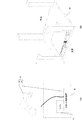
図1Aは、本発明の一実施形態であるロボットシステム10の構成を示すブロック図である。本実施形態にかかるロボットシステム10は、ロボット制御装置20とロボット30とを備えている。ロボット制御装置20は、ロボット30を制御するための各種の回路を備えている。ロボット30は、複数の駆動部が駆動されることによって所定の機能を実現できるように構成されている。本実施形態において、各駆動部はモーターによって駆動される。ロボット制御装置20とロボット30とは外部配線で接続されており、当該外部配線を介してロボット制御装置20とロボット30との間で電力および信号が授受される。
(1) Configuration of robot controller:
FIG. 1A is a block diagram illustrating a configuration of a
さらに、ロボット制御装置20には、図示しない外部配線を介して外部電源から電力を供給することが可能である。本実施形態において、ロボット30は、セル40の上部に設置されている。セル40は、内側にロボット制御装置20を含む各種の装置を設置可能な構造体であり、本実施形態においては直方体の部材と当該直方体の一面の4隅において当該一面と垂直な方向に延びる角柱状の部材とを有する構造体である。なお、図1Aにおいては、セル40に、ロボット制御装置20以外の装置としてUPS(Uninterruptible Power Supply)41が設置されている例を示している。
Further, power can be supplied to the
図1Bは、セル40にロボット制御装置20が設置された状態を示す斜視図である。本実施形態においては、ロボット30やロボット制御装置20を利用者が操作する際に利用者が存在する位置をロボット制御装置20の正面と見なし、正面に対向する面を背面と見なす。また、鉛直方向に沿って上下を定義し、上面、底面、以外の面を側面と見なす。セル40の底面はほぼ正方形であり、例えば、600mm×600mmの面である。セル40においては当該底面に対して垂直に4個の角柱状の部材が延びるため、底面の一辺より若干短い長さの装置をセル40の内側に自由に出し入れし、設置することができる。
FIG. 1B is a perspective view illustrating a state where the
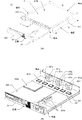
図2Aは、ロボット制御装置20を抜き出して示す斜視図である。本実施形態において、ロボット制御装置20は略直方体の外形であり、幅W(側面同士の距離)が440mm、奥行きD(正面と背面の距離)が430mm、高さH(上面と底面の距離)が70mmである。本実施形態において、ロボット制御装置20の筐体は、6面体の部分と、当該6面体の正面および側面に取り付けられたカバー230,231およびカバー210,211を備えている。
FIG. 2A is a perspective view showing the
(1−1)筐体の構成:
本実施形態において、ロボット制御装置20は分離可能である。すなわち、ロボット制御装置20の筐体は第1ユニット21と、ロボット30を制御するためのロボット制御部(後述する電源基板220、駆動基板221、制御基板222)が設けられた第2ユニット22とを備えている。第1ユニット21は、セル40に対してネジ等によって固定可能であり、セル40に第1ユニット21が設置された状態で第2ユニット22を第1ユニット21から引き出し、両者を分離することが可能である。
(1-1) Configuration of housing:
In the present embodiment, the
本実施形態において、第1ユニット21は、ロボット制御装置20の直方体の部分の上面と底面と側面とを構成し、第2ユニット22がロボット制御装置20の直方体の部分の正面と背面と底面とを構成する。すなわち、第1ユニット21は、開口部が矩形の筒状体であり、第2ユニットは、底面から正面と背面とが垂直に延びることで形成された構造体である。
In the present embodiment, the
このような面を有する構成において、第2ユニット22の背面は第1ユニット21の開口部から挿入可能な大きさおよび形状である。また、第2ユニット22の背面を第1ユニット21の開口部に挿入した状態で、第1ユニット21の底面の上に第2ユニット22の底面を配置させながら前後(正面および背面に垂直な方向)に移動させることが可能である。従って、本実施形態においては、セル40に設置された第1ユニット21から第2ユニット22を引き出すことが可能である。
In the configuration having such a surface, the rear surface of the
さらに、第1ユニット21は、当該第1ユニット21の第2ユニット22への挿入量を規制し、第1ユニット21の第2ユニット22からの引き出しは規制しない規制部を備えている。具体的には、第2ユニット22を第1ユニット21に挿入し、第2ユニットの背面が第1ユニット21の背面側の端面と一致した状態よりも奥側に第2ユニット22を挿入できないように規制するストッパが第1ユニット21に設けられている。当該ストッパは種々の構成によって実現可能であり、例えば、図5Bに示す斜視図には第1ユニット21に突出部210cが設けられ、当該突出部210cが第2ユニット22に接触することで挿入が規制される構成が示されている。
Further, the
この構成であれば、規制部により、第1ユニット21に対する第2ユニット22の過度の挿入が防止されて適正な位置決めがなされる。一方、第2ユニット22の引き出しの際には規制部によって規制されないため、第2ユニット22を第1ユニット21から引き出すことができる。むろん、第2ユニット22が第1ユニット21の規制部に規制された状態において、ネジ等によって第1ユニット21と第2ユニットとが固定されても良い。
With this configuration, the restricting portion prevents the
以上の構成によれば、ロボット制御装置20がセル40に設置された状態において、第2ユニット22を第1ユニット21から分離し、作業しやすい場所に運ぶことができる。従って、第2ユニット22が備えるロボット制御部を容易にメンテナンスすることが可能である。
According to the above configuration, in a state where the
(1−2)第2ユニットの内部構成:
図2Bは、第2ユニット22の内部構造を示す斜視図である。同図に示すように、第2ユニット22には、複数の基板が取り付けられている。具体的には、第2ユニット22には、電源基板220と駆動基板221と制御基板222とが取り付けられている。
(1-2) Internal configuration of the second unit:
FIG. 2B is a perspective view showing the internal structure of the
電源基板220は、電源回路を備えている。電源基板220に形成された電源回路は、駆動基板221および制御基板222に供給するための電力を生成する回路であり、外部電源から供給される電力(本実施形態においてはUPSから供給される電力)の周波数および電圧を変換し、各基板に供給する。このために、電源基板220には複数のトランスやノイズフィルターなどの実装部品220aが実装されている。
The
駆動基板221は、電源基板220から供給された電力によってロボット30を駆動する駆動回路を備えている。駆動基板221に形成された駆動回路は、ロボット30が備える各モーターを駆動するための回路であり、1個のモーターに供給するための電力を1個のチップで生成する。従って、本実施形態においては、複数個のモーターのそれぞれに電力を供給するために、駆動基板221にチップが複数個(221a〜221f)実装されている。本実施形態において、チップ221a〜221fは、電源基板220から供給された電力の周波数と電圧とを三相交流に変換する回路を備えており、ロボット30の各モーターは三相交流で駆動される。
The
以上のように、本実施形態においては、ロボット30が備える各駆動部が単一の駆動基板221上の駆動回路によって駆動される。すなわち、本実施形態においては、1個のモーターに供給するための電力を1個のチップ(221a〜221fのいずれか)で生成しており、全てのチップ221a〜221fが単一の駆動基板221上に実装されている。従って、本実施形態においては、ロボット30のモーターに対して供給すべき全ての電力が一枚の駆動基板221上の駆動回路で生成されている。従って、複数の駆動部を複数の駆動基板で駆動する構成と比較して、薄い空間内に駆動回路を形成することができる。従って、容易にロボット制御装置20を薄型化することができる。
As described above, in the present embodiment, each drive unit included in the robot 30 is driven by the drive circuit on the
制御基板222は、ロボット30を制御する制御回路を備えている。制御基板222に形成された制御回路は、ロボット30の動作を制御する回路であり、CPU,ROM,RAM等によって構成される制御部222aを備えている。制御部222aは、所定の制御プログラムを実行可能であり、当該制御プログラムに従って制御部222a等がロボット30に対して制御信号を出力することで、ロボット30に所定の動作を実行させる。
The
ロボット制御装置20は、上述の電源基板220と駆動基板221と制御基板222とを備えているが、本実施形態において、駆動基板221および制御基板222は、電源基板220の最大高さ部分の高さ方向の範囲内に配置されている。ここで、電源基板220において、その最大高さ部分は電源基板220の実装部品220aの中で最も高さの高い部分であり、最大高さ部分の高さ方向の範囲は、実装部品220aの中で最も高さの高い部分の高さ(図2Bに示すHmax)と電源基板220の厚さとの和によって形成される範囲Rである。すなわち、電源基板220の最大高さ部分の高さ方向の範囲Rは、電源基板220の高さ方向の両端に挟まれた範囲である。
The
本実施形態においては、駆動基板221と制御基板222とが当該範囲Rに含まれるように、すなわち、範囲Rよりも高さ方向の上下にはみ出さないように配置されている。従って、本実施形態においては、電源基板220、駆動基板221および制御基板222からなる構造体の高さが、電源基板220の最大高さを超えることはない。このため、電源基板220、駆動基板221および制御基板222を備えるロボット制御装置20の高さ方向の大きさが過度に大きくなることを防止することができる。このため、ロボット制御装置20を小型化することが可能になる。
In the present embodiment, the
なお、本実施形態においては、駆動基板221と制御基板222とが、電源基板220と同一平面上に配置されることにより、駆動基板221および制御基板222が電源基板220の最大高さ部分の高さ方向の範囲内に含まれるように構成されている。以上の構成であれば、電源基板220の最大高さ部分の高さ方向の範囲内に駆動基板221を容易に配置することが可能になる。また、以上の構成によれば、各基板が同一平面上に配置されていない構成と比較して、各基板や基板上の回路、実装部品等の視認性が向上し、部品等に関する作業も容易になる。
In the present embodiment, the
さらに、各基板が同一平面上に配置されていない構成と比較して、回路設計の自由度が高くなる。例えば、各基板が同一平面上に配置されていない構成において、基板間に接続される内部配線の端子を基板の縁に配置すると作業性が低下するため、端子の位置が制約されやすい。しかし、各基板が同一平面上に配置されていれば、端子を基板の縁に配置しても内部配線を接続可能である。 Further, the degree of freedom in circuit design is higher than in a configuration in which each substrate is not arranged on the same plane. For example, in a configuration in which the substrates are not arranged on the same plane, if the terminals of the internal wiring connected between the substrates are arranged on the edge of the substrates, the workability is reduced, and the positions of the terminals are likely to be restricted. However, if the boards are arranged on the same plane, the internal wiring can be connected even if the terminals are arranged on the edge of the board.
なお、ロボット制御装置20の内部に配置される回路においては、一般に、外部電源から電力の供給を受けて電力変換等を行う電源回路の容積が最も大きい。すなわち、電源基板220上に電源回路を構成するためには、トランスなど、基板の実装面から高さ方向に基板厚よりも大きい高さを有するバルク状の部品が必要になる。一方、駆動基板221においては、電源基板220で処理済みの電力を受けモーター駆動用の三相交流を生成すれば良いため、バルク状の部品の高さを、電源基板220上の実装部品220aよりも小さいチップ221a〜221fとすることができる。制御基板222においても同様であり、バルク状の部品の高さを、電源基板220上の実装部品220aよりも小さくすることができる。
Note that, in a circuit arranged inside the
従って、本実施形態においては、電源基板220の最大高さ>駆動基板221の最大高さであり、かつ、電源基板220の最大高さ>制御基板222の最大高さとなる。このため、本実施形態のように、駆動基板221および制御基板222を、電源基板220の最大高さ部分の高さ方向の範囲内に配置することにより、ロボット制御装置20の高さを薄くすることが可能になる。
Therefore, in the present embodiment, the maximum height of the
さらに、本実施形態においては、電源基板220と駆動基板221と制御基板222とが、これらの電源基板220と駆動基板221と制御基板222を筐体の上面から見た場合に重ならない位置に配置されている。すなわち、複数の基板を底面に垂直な方向に投影した場合に、底面上での複数の基板の投影図が重ならない構成となっている。この構成によれば、ある基板のメンテナンスを行う際に他の基板が障害になりにくい。
Further, in the present embodiment, the
本実施形態においては、電源基板220、制御基板222が正面側に配置され、駆動基板221が背面側に配置されており、複数の基板のうち外部配線へのインターフェイスが最も多い基板は、複数の基板のうち外部配線へのインターフェイスが最も少ない基板よりも、筐体の内部において筐体の正面の近くに配置されている。すなわち、第1ユニット21および第2ユニットを備える筐体内の電源基板220、駆動基板221、制御基板222には筐体の外部に存在する外部配線によって電力や信号が供給され、また、筐体内の基板から外部配線によって外部のロボット30等に電力や信号が供給される。
In the present embodiment, the
図2Bに示すように、第2ユニット22の正面には各種のコネクタを取り付けるための穴が形成されており、これらの穴を通して筐体内の各基板と外部の装置(UPSやロボット30等)が接続される。当該コネクタには外部配線を接続する必要があるため、少数の箇所に集約されていることが好ましく、本実施形態においては、第2ユニット22の正面のみに外部配線を接続できるようにコネクタのための穴が設けられている(第2ユニット22の正面以外の面にはコネクタの穴が設けられていない)。
As shown in FIG. 2B, holes for attaching various connectors are formed on the front surface of the
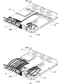
通常、基板から延びる内部配線をコネクタ等の接続部を介して外部配線に接続するが、このような接続を行うために接続すべき内部配線の数は基板によって異なる。そこで、外部配線へのインターフェイス(本例では外部配線に接続される内部配線)が最も多い基板は、外部配線へのインターフェイスが最も少ない基板よりも、筐体の内部において筐体の正面の近くに配置されている構成とすれば、筐体内の内部配線を可能な限り筐体の正面に集約することができる。図3Aは、電源基板220,駆動基板221,制御基板222から第2ユニット22の正面に取り付けられるコネクタへ延びる内部配線を模式的に示す図であり、太い曲線によって内部配線を示している。本実施形態においては、同図3Aに示すように、制御基板222に接続される内部配線の数>電源基板220に接続される内部配線の数>駆動基板221に接続される内部配線の数である。
Normally, the internal wiring extending from the substrate is connected to the external wiring via a connection portion such as a connector, but the number of internal wirings to be connected to make such a connection differs depending on the substrate. Therefore, a board with the largest number of interfaces to external wiring (in this example, internal wiring connected to the outside wiring) is closer to the front of the casing inside the casing than a board with the least number of interfaces to external wiring. With the arrangement, the internal wiring in the housing can be concentrated on the front of the housing as much as possible. FIG. 3A is a diagram schematically showing internal wiring extending from the
各内部配線はコネクタ等の接続部に接続され、接続部には外部配線が接続されるため、接続される内部配線の数が制御基板222>電源基板220>駆動基板221となっている本実施形態においては、外部配線へのインターフェイスが最も多い基板は、外部配線へのインターフェイスが最も少ない基板よりも、筐体の内部において筐体の正面の近くに配置されていることになる。一方、図3Bは、第2ユニット22内での電源基板220,駆動基板221,制御基板222の位置を変更し、外部配線へのインターフェイスが最も少ない駆動基板221を筐体の正面の近くに配置した場合の構成例を示している。ここでも、太い曲線によって内部配線を示している。
Since each internal wiring is connected to a connection portion such as a connector, and an external wiring is connected to the connection portion, the number of connected internal wirings is
図3Bに示すように、外部配線へのインターフェイスが少ない基板がインターフェイスが多い基板よりも筐体の内部において筐体の正面の近くに配置されている構成においては、当該配置ではない図3Aに示す構成と比較して、内部配線の長さが長くなってしまう。すなわち、外部配線へのインターフェイスが多い基板が筐体の正面から遠い位置に配置されていると、多数の内部配線において長い配線が必要になる。この結果、内部配線の取り回しが困難になるとともに筐体内に多くの内部配線が存在することになってしまう。しかし、外部配線へのインターフェイスが相対的に多い基板が相対的に少ない基板よりも正面の近くに配置されていれば、内部配線を最小化することが可能になる。さらに、外部配線への接続部が筐体の正面に集約されていると、ロボット制御装置20の利用者は、ロボット制御装置20の正面においてのみ外部配線の接続作業をすれば良く、メンテナンス作業が極めて容易になる。
As shown in FIG. 3B, in a configuration in which a board with a small interface to external wiring is arranged closer to the front of the casing inside the casing than a board with a large number of interfaces, this arrangement is not shown in FIG. 3A. The length of the internal wiring is longer than that of the configuration. That is, if a board having many interfaces to external wiring is arranged at a position far from the front of the housing, a long wiring is required for many internal wirings. As a result, it becomes difficult to manage the internal wiring, and many internal wirings are present in the housing. However, if a substrate having a relatively large number of interfaces to external wiring is arranged closer to the front than a substrate having a relatively small number of interfaces, the internal wiring can be minimized. Furthermore, when the connection parts to the external wiring are concentrated on the front of the housing, the user of the
さらに、本実施形態においては、図2Bに示すように第2ユニットの背面にファン221gが設けられている。すなわち、第2ユニットの背面においては、駆動基板221の上部かつ筐体の内側にファン221gの本体が配置されるようにファン221gが取り付けられている。この結果、本実施形態においては、電源基板220および制御基板222よりも駆動基板221に近い位置にファン221gが配置された状態となる。
Further, in the present embodiment, as shown in FIG. 2B, a
本実施形態においてロボット30は複数の駆動部を備え、各駆動部を駆動するモーターがチップ221a〜221fで駆動される。これらのチップ221a〜221fは、モーターを駆動するための電力を生成するための電力変換部等を備えているため、駆動基板221上には、ロボット30のモーターの数と同数の発熱体(チップ221a〜221f)が存在することになる。そこで、電源基板220よりも駆動基板221に近い位置にファン221gを配置すれば、効率的に駆動基板221のチップ221a〜221fを冷却することが可能になる。
In the present embodiment, the robot 30 includes a plurality of driving units, and motors for driving the respective driving units are driven by the
なお、本実施形態においてファン221gは筐体の背面に取り付けられる(図5B参照)ため、筐体の正面側で作業し得る利用者と遠い位置にファン221gを配置することができ、騒音対策になる。さらに、本実施形態においては、ファン221gが第2ユニット22の背面に位置するため、第2ユニット22を第1ユニット21から引き出すことによってファン221gとともに第2ユニット22を第1ユニット21から分離することが可能であり、容易にファン221gのメンテナンスを行うことが可能になる。
In this embodiment, since the
以上のように、本実施形態においては、駆動基板221および制御基板222を、電源基板220の最大高さ部分の高さ方向の範囲内に配置することにより、ロボット制御装置20を薄型化する構成が採用されている。この結果、ロボット制御装置20の筐体の高さが70mmとなり、ラックマウントの規格の2U(1.75インチ×2)の範囲に設置可能なロボット制御装置20を提供することができる。
As described above, in the present embodiment, the
(1−3)カバーの構成:
図4A,図4Bはカバー230、図4C,図4Dはカバー231、図4Eはカバー211、図4Fはカバー210の構造を示す斜視図である。なお、図4Aはカバー230を図2Aと同様の方向から見た状態、図4Bはカバー230を図2Aの背面側から見た状態であり、図4Cはカバー231を図2Aと同様の方向から見た状態、図4Dはカバー231を図2Aの背面側から見た状態である。図4Eおよび図4Fは、カバー211,210を図2Aと同様の方向から見た状態であり、各カバー211,210を分離した状態で示している。
(1-3) Configuration of cover:
4A and 4B are perspective views illustrating the structure of the
カバー230は、図4A,図4Bに示すように薄い板状の部材によって構成され、直方体の6面のうち、2面(図2Aに示す方向における背面と1個の側面)が省略された概略形状であり、1個の稜が丸い形状となっている。カバー231は、図4C,図4Dに示すように、カバー230と同様の構造であるが、直方体の6面から省略された側面がカバー230と異なる位置の側面である。すなわち、カバー230は、図2Aに示す筐体の正面においてカバー210側に取り付けられ、この状態において当該カバー210側が開口する形状であり、カバー231は、図2Aに示す筐体の正面においてカバー211側に取り付けられ、この状態において当該カバー211側が開口する形状である。さらに、カバー230,231では長さと高さが異なる。すなわち、カバー230は、カバー231よりも図2Aに示す幅方向の長さが長く、カバー230は、カバー231よりも図2Aに示す高さ方向の長さが短い。この結果、カバー230が第2ユニット22の正面に取り付けられた状態においてカバー230の上方に通気口が露出し、カバー230,231の間において第2ユニット22の正面の一部のコネクタが露出するように構成されている。
The
カバー211は、図4Eに示すように薄い板状の部材によって構成され、矩形の薄い板状の第1部材211aと、互いに直交する2個の矩形の面を備える第2部材211bとを備える。第1部材211aの矩形の面と、第2部材211bが備える小さい方の矩形の面はほぼ同一の形状であり、両面を対向させた状態で第1部材211aを第2部材211bに取り付けることができる。カバー210は、図4Fと同様の構造である。なお、本実施形態においてカバー210,211は、図2Aの奥行き方向の長さが同一であり、第1ユニット21の奥行き方向の長さよりも短い。むろん、カバー210,211の長さは異なっていてもよい。例えば、カバー210,211の一方において、奥行き方向の長さが第1ユニット21の奥行き方向の長さと一致していてもよい。
The
カバー230,231およびカバー210,211は、各カバーの内側(カバーと筐体の外面との間)の空間が外部配線の通路となるように筐体に取り付けられる。具体的には、カバー230,231はロボット制御装置20の筐体の正面に取り付けられる。また、各カバー230,231とロボット制御装置20の筐体の正面とで形成される空間が側面側で開口するように各カバー230,231が取り付けられる。図5A、図5Bは、ロボット制御装置20の正面の接続部(コネクタ等)に外部配線が取り付けられた状態で、カバー230,231およびカバー210,211がロボット制御装置20の筐体に取り付けられている状態を示す斜視図である。
The
同図5A,図5Bにおいては黒い実線の曲線で外部配線を示しており、図5Aは正面側、図5Bは背面側からロボット制御装置20を眺めた状態を示す図である。本実施形態において、カバー230,231がロボット制御装置20の筐体の正面に取り付けられると、同図5A,図5Bに示すように、側面側に開口部が形成される。本実施形態においてはロボット制御装置20の筐体の正面の接続部に接続された外部配線がカバー230,231と筐体の正面との間を通り、側面側の開口部側に引き回されている。
5A and 5B, the external wiring is indicated by a black solid line curve. FIG. 5A is a diagram showing a state in which the
カバー210,211は、ロボット制御装置20の筐体の側面に取り付けられる。カバー210,211が側面に取り付けられると、各カバー210,211とロボット制御装置20の筐体の側面との間に空間が形成され、正面側と背面側とが開口した状態になる。本実施形態においてはカバー230,231とロボット制御装置20の筐体の正面との間に形成される開口部から引き回された外部配線が、カバー210,211と筐体の側面との間を通り、背面側に引き回されている。以上のように、本実施形態においては、カバー230,231,210,211によって正面および側面に沿って外部配線が背面側へ引き回されている。なお、第2ユニット22の正面においては、カバー230,231に覆われていないコネクタも存在する。これらのコネクタに接続される外部配線は、例えば、利用者が第2ユニット22の正面において作業をする際等に利用される。
The
本実施形態において、カバー230,231は着脱可能である。カバー230,231を着脱可能にするための構成は、種々の構成を採用可能であり、例えば、ネジ等によって着脱する構成等を採用可能である。さらに、本実施形態においては、図2Bに示すように、第2ユニット22の正面(ロボット制御装置20の筐体の正面)のみに外部配線の接続部が設けられている。従って、利用者は、ロボット制御装置20がセル40に設置され、カバー230,231が取り外された状態で第2ユニット22の正面に存在する接続部に容易に外部配線を着脱することが可能である。
In the present embodiment, the
さらに、本実施形態においては、ロボット制御装置20がセル40に設置された状態で第1ユニット21から第2ユニット22を引き出して両者を分離することが可能である。そして、第2ユニット22の正面の接続部から外部配線を取り外した状態で第2ユニット22を第1ユニット21から引き出せば、外部配線を第1ユニット21側(カバー210および211と第1ユニット21の側面との間)に残した状態で第2ユニット22を引き出すことが可能である。従って、外部配線を接続部から取り外した状態とすれば、外部配線に負荷を与えることなく設置部に設置された状態の第2ユニット22を容易に引き出すことが可能である。
Further, in the present embodiment, it is possible to pull out the
また、第2ユニット22を第1ユニット21に取り付ける際には、第1ユニット21がセル40に設置された状態で第1ユニット21に第2ユニット22を挿入し、その後、接続部に外部配線を取り付ければ良い。従って、第2ユニット22の内部に設置される各基板のメンテナンスをする際に外部配線を引き出す必要はなく、ロボット制御装置20がセル40に設置された後、外部配線を引っ張るなどの作業は発生しない。このため、本実施形態においては、外部配線の長さがセル40に設置可能な長さになるように予め決められた状態に固定することが可能である。従って、外部配線の余長管理が容易になる。
When attaching the
さらに、以上の構成において、外部配線は、カバー230,231,210,211によって形成される既定の通路を通り、ロボット制御装置20の正面から側面に沿って背面の方向に向けられることになる。従って、ロボット制御装置20においては、カバー230,231に覆われた接続部に接続された全ての外部配線を正面から背面に引き回すことが可能になる。また、カバーによって外部配線が引き回されるため、外部配線の長さはカバーによって規定され、過度に長くなることがない。従って、ロボット制御装置20の外部における外部配線の管理が容易になる。
Further, in the above configuration, the external wiring passes through the predetermined passage formed by the
さらに、カバー230,231は、第2ユニット22の正面から着脱可能であるため、筐体から取り外した状態で外部配線を筐体の正面に接続することが可能になり、接続作業が容易になる。また、カバー210は、第1部材210aおよび第2部材210bに分離可能であり、カバー211は、第1部材211aおよび第2部材211bに分離可能である。従って、第1ユニット21の側面に第2部材210b、211bが取り付けられた状態で第1部材210a,211aを取り外せば、外部配線を第1ユニット21の側面とカバー210,211との間に配置する作業を極めて容易に行うことが可能である。
Furthermore, since the
さらに、本実施形態においては、カバー210,211によって外部配線を背面側に引き回すことが可能であり、第1ユニット21の側面において外部配線のために過度に広い空間が必要にならない。従って、幅方向の長さが規定され得る構成、例えば、ラックマウントに設置可能なロボット制御装置20等において、幅方向の端面を構成する側面側に外部配線のために過度に広い空間を確保する必要がない。このため、幅方向の長さが規定され得る構成であっても、ロボット制御装置20の幅を過度に小さくする必要はなく、ロボット制御装置20の内部空間を十分に広くすることができる。
Further, in the present embodiment, the external wiring can be routed to the rear side by the
さらに、カバー210,211の奥行き方向の長さは第1ユニット21の奥行き方向の長さより短い。すなわち、カバー210,211における背面側の端面は、筐体の背面よりも正面側に位置する。従って、図5A,図5Bに示す外部配線Iのように、外部配線を背面側ではなく側面側から他の部位へ引き回すことが可能になる。
Further, the length of the
(2)他の実施形態:
以上の実施形態は本発明を実施するための一例であり、他にも種々の実施形態を採用可能である。例えば、ロボットシステム10の態様は、図1Aに示す態様に限定されず、双腕ロボットや人型ロボット、スカラーロボットなど、他のいかなるロボットであっても良い。さらに、ロボット制御装置は薄型であればよく、駆動基板221が電源基板220の最大高さ部分の高さ方向の範囲外に存在する構成で薄型化を図ってもよい。すなわち、電源基板220の厚さ方向において、電源回路が設けられた電源基板の面と駆動回路221が設けられた駆動基板の面との間の距離が、電源基板220の最大高さ(図2Bに示すR)よりも短い構成であっても良い。
(2) Other embodiments:
The above embodiment is an example for carrying out the present invention, and other various embodiments can be adopted. For example, the form of the
さらに、上述のロボット制御装置20の構成の一部が省略、または置換された構成であっても良い。例えば、カバー230,231の少なくとも一部が省略され、主に、側面のカバー210,211によって外部配線が筐体の正面および側面に沿って背面に引き回される構成であってもよい。
Further, a configuration in which a part of the configuration of the above-described
さらに、ロボット制御装置20に対して他の構成が追加されていてもよい。例えば、第2ユニットに、底面に平行な把手が設けられている構成であっても良い。図5Cは、当該把手を備える第2ユニット22aの一部を抜き出して示す斜視図である。同図5Cにおいて、第2ユニット22aは第2ユニット22とほぼ同様の構成であるが、その正面に把手22bを備える点で両者は異なっている。把手22bは、棒状の部材によって構成されており、第2ユニット22aの正面に垂直に延びる2本の部位と、各部位をつなぐように第2ユニット22aの正面に平行に延びる1本の部位とを備えている。
Further, another configuration may be added to the
各部位が延びる方向は、第2ユニット22aの底面に対して平行であり、この意味で把手22bは底面に平行である。図5Cに示す例において、把手22bは、第2ユニット22aの正面の下部に取り付けられているため、当該正面の裏側に存在する第2ユニット22aの底面に近い位置に取り付けられている。以上の構成によれば、利用者は把手22bを利用して容易に第2ユニット22を引き出すことが可能である。また、把手22bによって第2ユニット22aに作用する力が第2ユニット22aの正面を撓ませるよりも、底面を引き出す力として作用しやすく、この意味でも利用者は容易に第2ユニット22を引き出すことが可能である。
The direction in which each part extends is parallel to the bottom surface of the
さらに、図5Cに示す構成において、筐体の正面側における把手22bの端面E2は、当該正面側における筐体の端面E1よりも背面側に存在する。このため、第2ユニット22aを第1ユニット21に挿入した状態において、最も正面側に位置する端面は筐体の端面E1であり、把手22bの端面E2は筐体の端面E1より奥側(背面側)に位置している。この構成によれば、把手22bが正面側に突出することがなく、カバー230,231等に関して利用者が作業する際に、把手22bが利用者等の作業等の障害になることはない。
Further, in the configuration shown in FIG. 5C, the end surface E 2 of the
電源基板は、電源回路を含んでいれば良く、電源回路は、他の回路(他の基板やロボット)に供給するための電力を生成することができればよい。このような電源回路は、例えば、ロボット制御部の設置箇所にて供給される外部電源(例えば商用電源)から電力の供給を受け、電圧変換や周波数変換(直流/交流の変換を含む)を行って他の回路に供給するための電力を生成する回路によって構成可能である。 The power supply board only needs to include a power supply circuit, and the power supply circuit only needs to be able to generate power to be supplied to another circuit (another substrate or a robot). Such a power supply circuit receives, for example, power from an external power supply (for example, a commercial power supply) supplied at a location where the robot control unit is installed, and performs voltage conversion and frequency conversion (including DC / AC conversion). And a circuit that generates electric power to be supplied to another circuit.
駆動基板は、電源基板から供給された電力によってロボットを駆動する駆動回路を含んでいれば良く、駆動回路は、ロボットを駆動することができればよい。すなわち、ロボットは、少なくとも1個以上の駆動部が駆動されることによって所定の機能を実現するように構成されており、駆動回路は当該駆動部を駆動する回路によって構成される。ロボットの駆動部は、種々の機構によって駆動されて良く、例えば、モーターやソレノイド等を備える駆動部が動作することによってロボットの駆動部(関節等)が駆動される構成等が挙げられる。 The drive board only needs to include a drive circuit that drives the robot with electric power supplied from the power supply board, and the drive circuit only needs to be able to drive the robot. That is, the robot is configured to realize a predetermined function by driving at least one or more drive units, and the drive circuit is configured by a circuit that drives the drive units. The drive unit of the robot may be driven by various mechanisms. For example, a configuration in which the drive unit (joint or the like) of the robot is driven by the operation of a drive unit including a motor, a solenoid, and the like.
なお、ロボット制御装置の内部に配置される回路においては、一般に、外部電源から電力の供給を受けて電力変換等を行う電源回路の容積が最も大きい。すなわち、電源回路を構成するためには多くの場合、基板の実装面から高さ方向に基板厚よりも大きい高さを有するバルク状の部品(トランス等)を実装する必要がある。一方、駆動基板は、電源基板によって外部電源からの供給電力が変換された後の電力を使用する駆動回路を備えるため、一般に、電源回路の容積よりも小さい容積によって駆動回路を構成可能である。 In addition, in a circuit arranged inside the robot control device, generally, a power supply circuit that receives power supply from an external power supply and performs power conversion or the like has the largest capacity. That is, in many cases, it is necessary to mount a bulk component (such as a transformer) having a height greater than the substrate thickness in the height direction from the mounting surface of the substrate in order to configure the power supply circuit. On the other hand, since the drive board includes a drive circuit that uses the power after the power supplied from the external power supply is converted by the power supply board, the drive circuit can generally be configured with a smaller volume than the power supply circuit.
このような場合、電源基板の最大高さ>駆動基板の最大高さとなるため、駆動基板を、電源基板の最大高さ部分の高さ方向の範囲内に配置することにより、ロボット制御装置の高さを薄くすることが可能になる(ロボット制御装置の高さの制約が実質的に電源基板の最大高さに限定され、他の基板に影響されない)。なお、駆動基板が備える駆動回路において、電力変換や電力の周波数変換を行う回路が備えられていても良いが、これらの回路は、外部電源から直接的に電力を供給される回路ではないため、駆動回路の構成部品は電源回路の構成部品より小さい。このため、電源基板の最大高さ>駆動基板の最大高さという状態を実現することができる。 In such a case, since the maximum height of the power supply board is greater than the maximum height of the drive board, the drive board is disposed within the range of the maximum height of the power supply board in the height direction, so that the height of the robot control device is increased. It is possible to reduce the height (the restriction on the height of the robot controller is substantially limited to the maximum height of the power supply board, and is not affected by other boards). Note that in a driving circuit included in the driving substrate, a circuit for performing power conversion or frequency conversion of power may be provided. However, since these circuits are not circuits to which power is directly supplied from an external power supply, The components of the drive circuit are smaller than the components of the power supply circuit. For this reason, the state where the maximum height of the power supply board is greater than the maximum height of the drive board can be realized.
駆動基板を、電源基板の最大高さ部分の高さ方向の範囲内に配置するための構成としては、種々の構成が採用可能である。すなわち、駆動回路を含む駆動基板の高さ方向の上端の位置が、電源回路を含む駆動基板の高さ方向の上端の位置より下方(または等しい位置)であり、駆動回路を含む駆動基板の高さ方向の下端の位置が、電源回路を含む駆動基板の高さ方向の下端の位置より上方(または等しい位置)であればよく、この範囲であれば、任意の位置に駆動基板を配置可能である。なお、高さ方向は、基板の実装面に垂直な方向であれば良く、当該方向を高さ方向とした場合において、高さ方向に垂直であるとともに互いに直交する2方向に幅方向と奥行き方向とを定義することが可能である。 Various configurations can be adopted as a configuration for disposing the drive substrate within a range in the height direction of the maximum height portion of the power supply substrate. That is, the position of the upper end of the drive board including the drive circuit in the height direction is lower than (or equal to) the position of the upper end of the drive board including the power supply circuit in the height direction, and the height of the drive board including the drive circuit is higher. The position of the lower end in the vertical direction may be above (or equal to) the position of the lower end in the height direction of the drive board including the power supply circuit, and within this range, the drive board can be arranged at any position. is there. The height direction may be any direction as long as it is perpendicular to the mounting surface of the substrate. When the direction is the height direction, the width direction and the depth direction are perpendicular to the height direction and orthogonal to each other. It is possible to define
なお、ロボット制御装置において最も大きい容積を占める(高さ方向に最も高い部品を有する)のは、一般的に電源回路であるため、駆動基板を、電源基板の最大高さ部分の高さ方向の範囲内に配置することにより、ロボット制御装置を容易に薄型化することが可能になる。また、ロボット制御装置の内部において薄型化の制約となる最大の要因が電源基板である状況であれば、電源基板の最大高さ部分を収容可能な筐体によってロボット制御装置を構成することで薄型化が実現される。 It is generally a power supply circuit that occupies the largest volume in the robot controller (having the highest components in the height direction), and therefore, the drive board is moved in the height direction of the maximum height portion of the power supply board. By arranging the robot control device within the range, the robot control device can be easily reduced in thickness. In addition, if the power supply board is the largest factor constraining the thickness reduction inside the robot control apparatus, the robot control apparatus can be made thin by configuring the robot control apparatus with a housing that can accommodate the maximum height of the power supply board. Is realized.
従って、このようにして薄型化されたロボット制御装置においては、電源基板の最大高さ部分の高さ方向の範囲内に含まれるのであれば、他の部品が筐体内に内蔵されていても良い。この場合、他の部品としては、バルク状の部品であっても良いし、他の基板であっても良い。他の基板は、電源基板や駆動基板と平行である(電源基板の実装面に垂直な基板が存在しない)ことが好ましいが、電源基板の最大高さ部分の高さ方向の範囲内に含まれるのであれば他の基板が電源基板の実装面に垂直に向いていても良い。 Therefore, in the robot controller thinned in this manner, other components may be incorporated in the housing as long as the components are included in the range in the height direction of the maximum height portion of the power supply board. . In this case, the other component may be a bulk component or another substrate. The other substrate is preferably parallel to the power supply substrate and the drive substrate (there is no substrate perpendicular to the mounting surface of the power supply substrate), but is included in the range of the maximum height of the power supply substrate in the height direction. In this case, the other substrate may be perpendicular to the mounting surface of the power supply substrate.
電源基板の最大高さ部分の高さ方向の範囲内に含まれるように駆動基板を配置する構成例として、駆動基板が、電源基板と同一平面上に配置されている構成を採用してもよい。当該構成であれば、電源基板の最大高さ部分の高さ方向の範囲内に駆動基板を容易に配置することが可能になる。また、以上の構成によれば、各基板が同一平面上に配置されていない構成と比較して、各基板や基板上の回路、実装部品等の視認性が向上し、部品等に関する作業も容易になる。むろん、ロボット制御装置が、他の基板、例えば、ロボットを制御する制御回路を含む制御基板を備える構成において、当該他の基板が電源基板と同一平面上に配置されている構成であっても良い。 As an example of a configuration in which the drive substrate is arranged so as to be included in the range in the height direction of the maximum height portion of the power supply substrate, a configuration in which the drive substrate is arranged on the same plane as the power supply substrate may be adopted. . With this configuration, it is possible to easily arrange the drive substrate within a range in the height direction of the maximum height portion of the power supply substrate. Further, according to the above configuration, the visibility of each substrate, the circuit on the substrate, the mounted components, etc. is improved, and the work on the components, etc. is easier than in the configuration in which each substrate is not arranged on the same plane. become. Of course, in a configuration in which the robot control device includes another substrate, for example, a control substrate including a control circuit for controlling the robot, the other substrate may be arranged on the same plane as the power supply substrate. .
基板を同一平面上に配置するためには、回路設計の自由度が高くなるように構成されていれば良い。例えば、各基板が同一平面上に配置されていない構成において、基板間に接続される内部配線(ロボット制御装置の内部の配線を内部配線、外部の配線を外部配線と呼ぶ)の端子を基板の縁に配置すると作業性が低下するため、端子の位置が制約されやすい。しかし、各基板が同一平面上に配置されていれば、端子を基板の縁に配置しても内部配線を接続可能であり、回路設計の自由度が高くなる。なお、同一平面上に基板が配置される状態は、各基板の基準位置(例えば,基板の底面や基板の実装面)が実質的に同一の平面上に配置されるようにして実現されていれば良く、多少の誤差(例えば、±10mm程度の取り付け位置の差異や基板の反り等)が存在したとしても各基板は同一平面上に存在すると見なされる。 In order to arrange the substrates on the same plane, it is sufficient that the substrates are configured so that the degree of freedom in circuit design is increased. For example, in a configuration in which the boards are not arranged on the same plane, the terminals of the internal wiring connected between the boards (the wiring inside the robot controller is called the internal wiring, and the wiring outside is called the external wiring). Since the workability is reduced when the terminals are arranged on the edge, the positions of the terminals are likely to be restricted. However, if the boards are arranged on the same plane, the internal wiring can be connected even if the terminals are arranged on the edge of the board, and the degree of freedom in circuit design is increased. The state where the substrates are arranged on the same plane is realized by setting the reference position of each substrate (for example, the bottom surface of the substrate or the mounting surface of the substrate) on the substantially same plane. Even if there is some error (for example, a difference in the mounting position of about ± 10 mm or warpage of the board), each board is considered to be present on the same plane.
筐体内に基板を備える構成において、筐体内の基板には各種の端子や内部配線を介して電力や信号が供給され、また、電力や信号が外部に送られる。このため、筐体の外面には、外部配線への接続部が設けられる必要がある。なお、接続部は、コネクタ等によって構成され、少数の箇所(好ましくは一カ所(多面体の筐体であれば特定の面))に集約されていることが好ましい。すなわち、接続部が多数の箇所に分散していると、メンテナンスが困難になる。例えば、接続部に対する外部配線の接続作業が繁雑となり、余長管理等も困難になる。 In a structure in which a substrate is provided in a housing, power and signals are supplied to the substrate in the housing via various terminals and internal wiring, and the power and signals are sent to the outside. Therefore, it is necessary to provide a connection portion to an external wiring on the outer surface of the housing. It is preferable that the connecting portion is constituted by a connector or the like and is integrated at a small number of points (preferably at one point (a specific surface in the case of a polyhedral housing)). That is, if the connecting portions are dispersed in many places, maintenance becomes difficult. For example, the work of connecting the external wiring to the connection part becomes complicated, and the management of extra length becomes difficult.
そこで、複数の基板のうち外部配線へのインターフェイスが最も多い基板は、複数の基板のうち外部配線へのインターフェイスが最も少ない基板よりも、筐体の内部において前記筐体の正面の近くに配置されている構成とすれば、筐体内の内部配線の多くを筐体の正面に集約することが容易になる。なお、外部配線への接続部(コネクタ等)が筐体の正面に集約されていると、ロボット制御装置の利用者は、ロボット制御装置の正面においてのみ外部配線の接続作業をすれば良く、メンテナンス作業が極めて容易になる。筐体の正面は、ロボット制御装置が設置部(セル等)に設置され、稼働する状態において、筐体から見て作業者が存在する方向の面であれば良い。この場合、筐体から見て作業者が存在する方向と逆側が背面となる。正面と背面以外はロボット制御装置の設置部への設置方向において変化し得るが、ロボット制御装置がほぼ直方体であるとともに薄い箱形の筐体である場合に、正面と背面に挟まれた面の中の大きい2面の一方を上面、他方を底面、残りの面を側面と見なすことができる。 Therefore, a board having the largest number of interfaces to external wiring among the plurality of boards is arranged closer to the front of the casing inside the casing than a board having the least number of interfaces to external wiring among the plurality of boards. With such a configuration, it becomes easy to concentrate much of the internal wiring in the housing on the front of the housing. If the connection parts (connectors, etc.) to the external wiring are integrated on the front of the housing, the user of the robot controller needs only to connect the external wiring only on the front of the robot controller, and the maintenance is performed. Work becomes extremely easy. The front surface of the housing may be any surface as long as the robot control device is installed in an installation section (eg, a cell) and is in a state where the worker is present when viewed from the housing in an operating state. In this case, the side opposite to the direction in which the worker exists as viewed from the housing is the back surface. Except for the front and back, it can vary in the installation direction of the robot controller in the installation section.However, when the robot controller is a substantially rectangular parallelepiped and a thin box-shaped casing, the surface sandwiched between the front and back is One of the two large surfaces can be regarded as a top surface, the other as a bottom surface, and the remaining surfaces as side surfaces.
一般にロボットは多関節であって各関節を個別に駆動するための個別の駆動部(モーターやソレノイド等)を複数個備える。駆動基板は、ロボットを駆動するための駆動回路を備えるため、複数の駆動部を駆動するための個別の回路(例えば、電力変換部等)を備える場合が多い。従って、駆動基板が備える駆動回路には複数個の発熱体(回路)が存在する場合が多い。このため、電源基板よりも駆動基板に近い位置に配置されたファンを備える構成であれば、効率的に駆動基板の駆動回路を冷却することが可能になる。むろん、筐体内に電源基板と駆動基板以外の基板が存在する場合、ファンに最も近い位置に駆動基板を配置することが好ましい。 Generally, a robot is a multi-joint and includes a plurality of individual drive units (motors, solenoids, etc.) for individually driving each joint. Since the drive substrate includes a drive circuit for driving the robot, the drive substrate often includes individual circuits (for example, a power conversion unit or the like) for driving a plurality of drive units. Therefore, a plurality of heating elements (circuits) are often present in a drive circuit provided in the drive board. Therefore, with a configuration including a fan arranged closer to the drive board than the power supply board, it is possible to efficiently cool the drive circuit of the drive board. Of course, when a board other than the power supply board and the drive board is present in the housing, it is preferable to dispose the drive board at a position closest to the fan.
ファンが筐体の正面と異なる面に位置する構成において、正面と異なる面は、側面、背面、上面、底面のいずれであっても良いが、利用者と最も遠い面である背面にファンが設けられていれば、より騒音低減効果が高く好ましい。 In a configuration in which the fan is located on a different surface from the front of the housing, the surface different from the front may be any of the side, the back, the top, and the bottom, but the fan is provided on the back, which is the surface farthest from the user. It is preferable that the noise reduction effect be higher.
ロボット制御装置の高さが30mm以上89mm以下である構成は、駆動基板を、電源基板の最大高さ部分の高さ方向の範囲内に配置することにより、容易に実現することが可能である。そして、当該高さの範囲は種々の値を採用可能であり、高さを1.75インチ(約44.45mm)以下とすれば、1Uの範囲に設置可能なロボット制御装置を提供することが可能である。 The configuration in which the height of the robot control device is 30 mm or more and 89 mm or less can be easily realized by arranging the drive board within the range of the maximum height of the power supply board in the height direction. Various values can be adopted as the range of the height. If the height is set to 1.75 inches (about 44.45 mm) or less, a robot control device that can be installed in a range of 1U can be provided. It is possible.
ロボット制御装置に接続される外部配線の少なくとも一部が、カバーによって正面および側面に沿って外部配線が引き回される構成においては、カバーに覆われた接続部に接続された全ての外部配線を正面から背面に引き回すことが可能になる。また、カバーによって外部配線が引き回されるため、外部配線の長さはカバーによって規定され、過度に長くなることがない。従って、ロボット制御装置の外部における外部配線の管理が容易になる。 In a configuration in which at least a part of the external wiring connected to the robot control device is routed along the front and side surfaces by the cover, all the external wiring connected to the connection portion covered by the cover is used. It can be routed from the front to the back. In addition, since the external wiring is routed by the cover, the length of the external wiring is defined by the cover and does not become excessively long. Therefore, management of the external wiring outside the robot controller becomes easy.
カバーは、筐体に取り付けられた状態で外部配線の通路を形成する部材であれば良く、当該通路が形成されることによって、外部配線が引き回される方向が特定されるように構成されていれば良い。例えば、筐体の面(正面や側面)に対向する面を有するカバーを構成すれば、当該対向する面と筐体の面との間が外部配線の通路となるカバーを構成することができる。カバーは、外部配線の通路を形成していれば良く、形状は限定されない。また、ロボット制御装置が備える外部配線の数に応じて形状が決定されて良い。さらに、カバーは第2ユニットに取り付けられていても良いし、第1ユニットに取り付けられていても良い。 The cover may be a member that forms a passage for external wiring when attached to the housing, and is configured such that the direction in which the external wiring is routed is specified by forming the passage. Just do it. For example, if a cover having a surface facing the surface (front or side surface) of the housing can be formed, a cover between the facing surface and the surface of the housing serving as a passage for external wiring can be formed. The cover is only required to form a passage for the external wiring, and the shape is not limited. Further, the shape may be determined according to the number of external wires provided in the robot control device. Further, the cover may be attached to the second unit or may be attached to the first unit.
筐体の外面において、筐体の正面のみに外部配線の接続部が設けられている構成においては、ロボット制御装置を設置部に設置する前に事前に外部配線を接続部に接続する必要はなく、設置部における外部配線の長さや経路を予め決められた状態に固定しても、ロボット制御装置に対する外部配線の接続が可能になる。従って、外部配線の管理が容易になる。また、外部配線を接続部から取り外した状態とすれば、外部配線に負荷を与えることなく設置部に設置された状態のロボット制御装置を容易に取り外すことが可能である。 In the configuration in which the connection portion of the external wiring is provided only on the front surface of the housing on the outer surface of the housing, it is not necessary to connect the external wiring to the connection portion before installing the robot controller in the installation portion. Even if the length and route of the external wiring in the installation section are fixed in a predetermined state, the connection of the external wiring to the robot control device becomes possible. Therefore, management of external wiring is facilitated. In addition, if the external wiring is removed from the connection portion, the robot control device installed in the installation portion can be easily removed without applying a load to the external wiring.
カバーの少なくとも一部が着脱可能である構成において、カバーにおいて取り外し可能な部位は、外部配線の接続作業を容易にするような形状および大きさであれば良く、カバー全体が取り外し可能であっても良い。また、複数のカバーが筐体に取り付けられる構成において、その一部が取り外し可能であっても良い。 In a configuration in which at least a part of the cover is removable, the removable portion of the cover may have any shape and size that facilitates connection work of external wiring, and the entire cover may be removable. good. In a configuration in which a plurality of covers are attached to the housing, a part of the covers may be removable.
幅方向の長さが規定され得る構成、例えば、ラックマウントに設置可能なロボット制御装置等において、外部配線が、筐体の側面に沿って筐体の背面側に引き回されている構成とすれば、幅方向の端面を構成する側面側に外部配線のために過度に広い空間を確保する必要がなく、ロボット制御装置として利用可能な空間として広い空間を確保することができる。 In a configuration in which the length in the width direction can be specified, for example, in a robot control device that can be installed on a rack mount, the external wiring is routed to the rear side of the housing along the side surface of the housing. For example, it is not necessary to secure an excessively large space for the external wiring on the side surface constituting the end face in the width direction, and a wide space can be secured as a space that can be used as a robot control device.
第2ユニットを、第1ユニットから引き出すことによって第1ユニットと分離可能である構成においては、第2ユニットは第1ユニットから分離することができるため、第2ユニットのメンテナンスを行うために、ロボット制御部の左右に広い空間は必要ない。従って、容易にメンテナンスを行うことが可能なロボット制御部を提供することが可能である。 In a configuration in which the second unit can be separated from the first unit by pulling out the second unit from the first unit, the second unit can be separated from the first unit. No large space is required on the left and right sides of the control unit. Therefore, it is possible to provide a robot control unit that can easily perform maintenance.
筐体は、第1ユニットと第2ユニットとを有していれば良く、これらの第1ユニットと第2ユニットとを含む筐体が、ロボット制御装置の外面を構成することで筐体を形成する。なお、ロボット制御部が設置部に設置される場合、筐体の一部、例えば、第1ユニットが設置部に対して固定されることが好ましい。 The housing only needs to have the first unit and the second unit, and the housing including the first unit and the second unit forms the housing by forming the outer surface of the robot controller. I do. When the robot control unit is installed in the installation unit, it is preferable that a part of the housing, for example, the first unit is fixed to the installation unit.
ロボット制御部は、ロボットを制御するための回路を備えており、回路を含む1以上の基板によって構成され得る。むろん、基板状の回路以外の回路、部品等によって構成されても良い。当該回路は、種々の機能を有する回路によって構成されて良く、例えば、外部電源から電力を供給され、電圧変換や周波数変換を行う回路や、ロボットの駆動部(モーターやアクチュエーター等)を駆動するための回路や、ロボットの可動部の動作を制御するための回路等が挙げられる。 The robot control unit includes a circuit for controlling the robot, and may be configured by one or more substrates including the circuit. Of course, it may be constituted by a circuit, a component, and the like other than the substrate-like circuit. The circuit may be configured by a circuit having various functions. For example, the circuit is supplied with electric power from an external power supply and performs voltage conversion and frequency conversion, and drives a driving unit (a motor or an actuator) of a robot. And a circuit for controlling the operation of the movable part of the robot.
第2ユニットは第1ユニットから引き出すことによって第1ユニットと分離可能であれば良い。従って、第2ユニットは第1ユニットに対して少なくとも1方向に移動させることが可能であり、第2ユニットと第1ユニットとが接触していない状態となるまで移動させることにより、第2ユニットを第1ユニットから分離できるように構成されていれば良い。 The second unit only needs to be able to be separated from the first unit by being pulled out from the first unit. Therefore, the second unit can be moved in at least one direction with respect to the first unit. By moving the second unit until the second unit is not in contact with the first unit, the second unit can be moved. What is necessary is just to be comprised so that separation from the 1st unit is possible.
第2ユニットを第1ユニットから引き出すための構成としては、種々の構成を採用可能であり、第2ユニットを第1ユニットに対して少なくとも1方向に相対的に移動させることができればよい。例えば、第1ユニットと第2ユニットとの接触部位が第2ユニットを一方向に移動させる形状となっている構成等を採用可能である。当該接触部位は第2ユニットの移動方向を規制するレール等であっても良いし、接触部位の形状自体が第2ユニットの移動方向を規制する形状であっても良い。後者としては、例えば、第1ユニットに第2ユニットを嵌めることができる凹部が形成されている構成や、第1ユニットが第2ユニットを挿入可能な形状である構成等が挙げられる。 Various configurations can be adopted as a configuration for pulling out the second unit from the first unit, as long as the second unit can be relatively moved in at least one direction with respect to the first unit. For example, a configuration in which the contact portion between the first unit and the second unit is shaped to move the second unit in one direction can be adopted. The contact portion may be a rail or the like that regulates the moving direction of the second unit, or the shape of the contact portion itself may be a shape that regulates the moving direction of the second unit. As the latter, for example, a configuration in which a recess in which the second unit can be fitted in the first unit, a configuration in which the first unit has a shape in which the second unit can be inserted, and the like are given.
規制部の構成としては、種々の構成を採用可能であり、第2ユニットの端面等の所定部位に接触することによって第2ユニットの移動を規制するストッパ等によって構成可能である。むろん、第2ユニットは、移動が規制された状態で第1ユニットに対して固定可能であっても良い。 Various configurations can be adopted as the configuration of the restricting portion, and can be configured by a stopper or the like that restricts the movement of the second unit by contacting a predetermined portion such as an end surface of the second unit. Of course, the second unit may be fixable to the first unit in a state where movement is restricted.
筐体は任意の形状であって良いが、筐体が直方体の部分を有し、第1ユニットが筐体の直方体の部分の上面と底面と側面とを構成し、第2ユニットが筐体の直方体の部分の正面と背面と底面とを構成しても良い。すなわち、第1ユニットが直方体における上面と底面と側面を構成し、第2ユニットが直方体における正面と背面と底面とを構成する場合、第1ユニットの底面の上に第2ユニットの底面を配置させながら前後(正面および背面に垂直な方向)に移動可能な構成とすれば、直方体の筐体において第1ユニットから引き出し可能な第2ユニットを構成することができる。この場合、第2ユニットは第1ユニットが備える各面の内側に挿入できるような大きさであれば良い。 The housing may have any shape, but the housing has a rectangular parallelepiped portion, the first unit forms the top, bottom, and side surfaces of the rectangular parallelepiped portion of the housing, and the second unit forms The front, back, and bottom surfaces of the rectangular parallelepiped may be configured. That is, when the first unit constitutes the top surface, the bottom surface, and the side surface of the rectangular parallelepiped, and the second unit constitutes the front surface, the back surface, and the bottom surface of the rectangular parallelepiped, the bottom surface of the second unit is arranged on the bottom surface of the first unit. If it is configured to be movable back and forth (in the direction perpendicular to the front and back), a second unit that can be pulled out of the first unit in a rectangular parallelepiped housing can be configured. In this case, the second unit only needs to be large enough to be inserted inside each surface of the first unit.
なお、第1ユニットが備える側面は、2面であっても良いし1面であっても良い。すなわち、側面が2面であれば矩形の開口部を有する筒状体によって第1ユニットが構成され、側面が1面であれば矩形の開口部を有する筒状体の1面が存在しない3面の構造体で第1ユニットが構成される。 The first unit may have two side surfaces or one side surface. In other words, if the number of side surfaces is two, the first unit is constituted by a cylindrical body having a rectangular opening, and if the number of side surfaces is one, the first surface of the cylindrical body having a rectangular opening does not exist. The first unit is constituted by the above structure.
ファンが筐体の正面と異なる面に位置する構成において、正面と異なる面は、側面、背面、上面、底面のいずれであっても良いが、利用者と最も遠い面である背面にファンが設けられていれば、より騒音低減効果が高く好ましい。さらに、ファンが背面に位置する構成であれば、第2ユニットを第1ユニットから引き出すことによってファンとともに第2ユニットを第1ユニットから分離することが可能であり、容易にファンのメンテナンスを行うことが可能になる。 In a configuration in which the fan is located on a different surface from the front of the housing, the surface different from the front may be any of the side, the back, the top, and the bottom, but the fan is provided on the back, which is the surface farthest from the user. It is preferable that the noise reduction effect be higher. Furthermore, if the fan is located on the back, the second unit can be separated from the first unit together with the fan by pulling out the second unit from the first unit, and the fan can be easily maintained. Becomes possible.
筐体の正面のみに外部配線の接続部が設けられている構成においては、設置部に設置された第1ユニットに第2ユニットを挿入した後に接続部への外部配線の着脱を行えばよい。従って、第2ユニットと第1ユニットとが分離した状態で接続部に外部配線を接続する必要はなく、設置部における外部配線の長さや経路を予め決められた状態に固定しても、接続部に対する外部配線の接続が可能になる。従って、外部配線の管理が容易になる。また、外部配線を接続部から取り外した状態とすれば、外部配線に負荷を与えることなく設置部に設置された状態の第2ユニットを容易に引き出すことが可能である。 In a configuration in which the connection portion of the external wiring is provided only on the front surface of the housing, the external wiring may be attached to and detached from the connection portion after the second unit is inserted into the first unit installed in the installation portion. Therefore, it is not necessary to connect the external wiring to the connection part in a state where the second unit and the first unit are separated, and even if the length and the route of the external wiring in the installation part are fixed in a predetermined state, Can be connected to external wiring. Therefore, management of external wiring is facilitated. Further, if the external wiring is detached from the connection part, the second unit installed in the installation part can be easily pulled out without applying a load to the external wiring.
10…ロボットシステム、20…ロボット制御装置、21…第1ユニット、22…第2ユニット、22a…ユニット、22b…把手、30…ロボット、40…セル、220…電源基板、220a…実装部品、221…駆動基板、221g…ファン、222…制御基板、222a…制御部、230,231,210,211…カバー
DESCRIPTION OF
Claims (9)
前記第1面と平行な第2面を有する駆動基板と、を備え、
前記第1面には、実装部品を有する電源回路が設けられており、
前記第2面には、前記電源基板から供給された電力によってロボットが有する第1のモーターを駆動する駆動回路が設けられており、
前記第1面と前記第2面との距離は、前記実装部品のうち前記第1面から最も離れた点と前記第1面との距離よりも短い、ロボット制御装置。 A power supply substrate having a first surface;
Comprising a driving substrate having a pre-Symbol second surface parallel to the first plane, and
A power supply circuit having a mounting component is provided on the first surface,
A drive circuit for driving a first motor of the robot with electric power supplied from the power supply board is provided on the second surface,
The robot controller according to claim 1, wherein a distance between the first surface and the second surface is shorter than a distance between a point of the mounted component farthest from the first surface and the first surface.
請求項1に記載のロボット制御装置。 The drive board is disposed on the same plane as the power supply board,
The robot control device according to claim 1.
前記筐体は、外部配線の接続部が設けられた第3面を有し、
前記複数の基板のうち前記外部配線へのインターフェイスが最も多い基板は、前記複数の基板のうち前記外部配線へのインターフェイスが最も少ない基板よりも、前記第3面の近くに配置されている、
請求項1または請求項2に記載のロボット制御装置。 A housing having a plurality of substrates including the power supply substrate and the drive substrate therein,
The housing has a third surface provided with a connection portion for external wiring,
The substrate having the largest number of interfaces to the external wiring among the plurality of substrates is disposed closer to the third surface than the substrate having the least number of interfaces to the external wiring among the plurality of substrates.
The robot control device according to claim 1 or 2.
請求項1〜請求項3のいずれかに記載のロボット制御装置。 A fan arranged at a position closer to the drive board than the power supply board,
The robot control device according to claim 1.
前記ファンは、前記第3面と異なる面に位置する、
請求項3に記載のロボット制御装置。 A fan arranged at a position closer to the drive board than the power supply board,
The fan is located on a surface different from the third surface;
The robot control device according to claim 3 .
前記制御基板は、前記電源基板と同一平面上に配置されている、
請求項1〜請求項5のいずれかに記載のロボット制御装置。 A control board including a control circuit for controlling the robot,
The control board is disposed on the same plane as the power supply board,
The robot control device according to claim 1.
前記第1のモーターと前記第2のモーターとは、同一の前記駆動基板によって駆動される、
請求項1〜請求項6のいずれかに記載のロボット制御装置。 The robot has a second motor;
The first motor and the second motor are driven by the same drive board,
The robot control device according to claim 1.
前記ロボット制御装置によって制御されるロボットと、を備える、ロボットシステム。 A robot control device according to any one of claims 1 to 7,
A robot controlled by the robot control device.
Priority Applications (4)
| Application Number | Priority Date | Filing Date | Title |
|---|---|---|---|
| JP2015161677A JP6657656B2 (en) | 2015-08-19 | 2015-08-19 | Robot controller, robot, robot system |
| US15/234,468 US10602611B2 (en) | 2015-08-19 | 2016-08-11 | Robot control apparatus, robot, and robot system |
| CN201610681736.9A CN106466845B (en) | 2015-08-19 | 2016-08-17 | Robot control device, robot, and robot system |
| EP16184483.2A EP3139716B1 (en) | 2015-08-19 | 2016-08-17 | Robot control apparatus, robot, and robot system |
Applications Claiming Priority (1)
| Application Number | Priority Date | Filing Date | Title |
|---|---|---|---|
| JP2015161677A JP6657656B2 (en) | 2015-08-19 | 2015-08-19 | Robot controller, robot, robot system |
Publications (3)
| Publication Number | Publication Date |
|---|---|
| JP2017039181A JP2017039181A (en) | 2017-02-23 |
| JP2017039181A5 JP2017039181A5 (en) | 2018-09-06 |
| JP6657656B2 true JP6657656B2 (en) | 2020-03-04 |
Family
ID=58205816
Family Applications (1)
| Application Number | Title | Priority Date | Filing Date |
|---|---|---|---|
| JP2015161677A Active JP6657656B2 (en) | 2015-08-19 | 2015-08-19 | Robot controller, robot, robot system |
Country Status (1)
| Country | Link |
|---|---|
| JP (1) | JP6657656B2 (en) |
Family Cites Families (13)
| Publication number | Priority date | Publication date | Assignee | Title |
|---|---|---|---|---|
| JPS6078190U (en) * | 1983-11-02 | 1985-05-31 | クラリオン株式会社 | Printed circuit board mounting mechanism |
| JPH0541178U (en) * | 1991-10-31 | 1993-06-01 | 日本ケミコン株式会社 | Wiring board connection device |
| JP4023047B2 (en) * | 1999-09-30 | 2007-12-19 | 株式会社デンソー | Electronic control unit |
| JP2005260027A (en) * | 2004-03-12 | 2005-09-22 | Mitsubishi Electric Corp | High-frequency circuit module |
| JP4373882B2 (en) * | 2004-08-31 | 2009-11-25 | 株式会社東芝 | Electronic device casing structure and communication device |
| JP4251197B2 (en) * | 2005-11-29 | 2009-04-08 | セイコーエプソン株式会社 | Robot control apparatus and robot system |
| JP4670611B2 (en) * | 2005-11-29 | 2011-04-13 | セイコーエプソン株式会社 | Robot controller |
| JP2007144589A (en) * | 2005-11-29 | 2007-06-14 | Seiko Epson Corp | Robot control device |
| US7403385B2 (en) * | 2006-03-06 | 2008-07-22 | Cisco Technology, Inc. | Efficient airflow management |
| JP5385000B2 (en) * | 2008-05-27 | 2014-01-08 | 株式会社ミツバ | Electric rotary joint |
| JP5803213B2 (en) * | 2011-03-30 | 2015-11-04 | セイコーエプソン株式会社 | Robot controller |
| JP2013065622A (en) * | 2011-09-15 | 2013-04-11 | Denso Wave Inc | Control device for production apparatus and manufacturing method of the same |
| KR20140084286A (en) * | 2011-11-28 | 2014-07-04 | 가부시키가이샤 야스카와덴키 | Substrate processing device and robot controller |
-
2015
- 2015-08-19 JP JP2015161677A patent/JP6657656B2/en active Active
Also Published As
| Publication number | Publication date |
|---|---|
| JP2017039181A (en) | 2017-02-23 |
Similar Documents
| Publication | Publication Date | Title |
|---|---|---|
| CN106466845B (en) | Robot control device, robot, and robot system | |
| JP4251197B2 (en) | Robot control apparatus and robot system | |
| US7428151B2 (en) | Cooling arrangement | |
| JP6673546B2 (en) | Controller assembly | |
| CN110876247B (en) | Electronic device and method for manufacturing electronic device | |
| WO2018155702A1 (en) | Electronic device and robot controller | |
| TWI613951B (en) | Motor drive | |
| JP6657656B2 (en) | Robot controller, robot, robot system | |
| JPH06284522A (en) | Control panel | |
| TWI527361B (en) | Motor drive | |
| JP2017039182A (en) | Robot control device, robot, and robot system | |
| JP2017039183A (en) | Robot control device, robot, and robot system | |
| KR101718201B1 (en) | Motor driving apparatus | |
| JP2007144589A (en) | Robot control device | |
| JP2013065695A (en) | Motor control device | |
| JP7100452B2 (en) | Electrical equipment | |
| JP2023028307A (en) | controller | |
| JP2007144588A (en) | Robot control device | |
| JP4737688B2 (en) | Electrical circuit device | |
| JP2023028306A (en) | controller | |
| JP2010098858A (en) | Inverter apparatus | |
| CN115915690A (en) | Controller | |
| JP2023028308A (en) | controller | |
| KR20210060581A (en) | Heat sink and control device having same | |
| JP5188427B2 (en) | Module mounting structure |
Legal Events
| Date | Code | Title | Description |
|---|---|---|---|
| A521 | Written amendment |
Free format text: JAPANESE INTERMEDIATE CODE: A523 Effective date: 20180724 |
|
| A621 | Written request for application examination |
Free format text: JAPANESE INTERMEDIATE CODE: A621 Effective date: 20180724 |
|
| RD05 | Notification of revocation of power of attorney |
Free format text: JAPANESE INTERMEDIATE CODE: A7425 Effective date: 20180906 |
|
| RD03 | Notification of appointment of power of attorney |
Free format text: JAPANESE INTERMEDIATE CODE: A7423 Effective date: 20181116 |
|
| A977 | Report on retrieval |
Free format text: JAPANESE INTERMEDIATE CODE: A971007 Effective date: 20190626 |
|
| A131 | Notification of reasons for refusal |
Free format text: JAPANESE INTERMEDIATE CODE: A131 Effective date: 20190702 |
|
| A521 | Written amendment |
Free format text: JAPANESE INTERMEDIATE CODE: A523 Effective date: 20190828 |
|
| TRDD | Decision of grant or rejection written | ||
| A01 | Written decision to grant a patent or to grant a registration (utility model) |
Free format text: JAPANESE INTERMEDIATE CODE: A01 Effective date: 20200107 |
|
| A61 | First payment of annual fees (during grant procedure) |
Free format text: JAPANESE INTERMEDIATE CODE: A61 Effective date: 20200120 |
|
| R150 | Certificate of patent or registration of utility model |
Ref document number: 6657656 Country of ref document: JP Free format text: JAPANESE INTERMEDIATE CODE: R150 |