JP6651941B2 - Switch device and control device for vehicle power supply - Google Patents
Switch device and control device for vehicle power supply Download PDFInfo
- Publication number
- JP6651941B2 JP6651941B2 JP2016067383A JP2016067383A JP6651941B2 JP 6651941 B2 JP6651941 B2 JP 6651941B2 JP 2016067383 A JP2016067383 A JP 2016067383A JP 2016067383 A JP2016067383 A JP 2016067383A JP 6651941 B2 JP6651941 B2 JP 6651941B2
- Authority
- JP
- Japan
- Prior art keywords
- switch
- vehicle
- storage device
- power storage
- control signal
- Prior art date
- Legal status (The legal status is an assumption and is not a legal conclusion. Google has not performed a legal analysis and makes no representation as to the accuracy of the status listed.)
- Active
Links
Images


Classifications
-
- H—ELECTRICITY
- H02—GENERATION; CONVERSION OR DISTRIBUTION OF ELECTRIC POWER
- H02H—EMERGENCY PROTECTIVE CIRCUIT ARRANGEMENTS
- H02H3/00—Emergency protective circuit arrangements for automatic disconnection directly responsive to an undesired change from normal electric working condition with or without subsequent reconnection ; integrated protection
- H02H3/16—Emergency protective circuit arrangements for automatic disconnection directly responsive to an undesired change from normal electric working condition with or without subsequent reconnection ; integrated protection responsive to fault current to earth, frame or mass
-
- B—PERFORMING OPERATIONS; TRANSPORTING
- B60—VEHICLES IN GENERAL
- B60R—VEHICLES, VEHICLE FITTINGS, OR VEHICLE PARTS, NOT OTHERWISE PROVIDED FOR
- B60R16/00—Electric or fluid circuits specially adapted for vehicles and not otherwise provided for; Arrangement of elements of electric or fluid circuits specially adapted for vehicles and not otherwise provided for
- B60R16/02—Electric or fluid circuits specially adapted for vehicles and not otherwise provided for; Arrangement of elements of electric or fluid circuits specially adapted for vehicles and not otherwise provided for electric constitutive elements
- B60R16/03—Electric or fluid circuits specially adapted for vehicles and not otherwise provided for; Arrangement of elements of electric or fluid circuits specially adapted for vehicles and not otherwise provided for electric constitutive elements for supply of electrical power to vehicle subsystems or for
- B60R16/033—Electric or fluid circuits specially adapted for vehicles and not otherwise provided for; Arrangement of elements of electric or fluid circuits specially adapted for vehicles and not otherwise provided for electric constitutive elements for supply of electrical power to vehicle subsystems or for characterised by the use of electrical cells or batteries
-
- H—ELECTRICITY
- H01—ELECTRIC ELEMENTS
- H01M—PROCESSES OR MEANS, e.g. BATTERIES, FOR THE DIRECT CONVERSION OF CHEMICAL ENERGY INTO ELECTRICAL ENERGY
- H01M10/00—Secondary cells; Manufacture thereof
- H01M10/42—Methods or arrangements for servicing or maintenance of secondary cells or secondary half-cells
- H01M10/425—Structural combination with electronic components, e.g. electronic circuits integrated to the outside of the casing
-
- H—ELECTRICITY
- H02—GENERATION; CONVERSION OR DISTRIBUTION OF ELECTRIC POWER
- H02H—EMERGENCY PROTECTIVE CIRCUIT ARRANGEMENTS
- H02H1/00—Details of emergency protective circuit arrangements
- H02H1/0007—Details of emergency protective circuit arrangements concerning the detecting means
-
- H—ELECTRICITY
- H02—GENERATION; CONVERSION OR DISTRIBUTION OF ELECTRIC POWER
- H02H—EMERGENCY PROTECTIVE CIRCUIT ARRANGEMENTS
- H02H3/00—Emergency protective circuit arrangements for automatic disconnection directly responsive to an undesired change from normal electric working condition with or without subsequent reconnection ; integrated protection
- H02H3/02—Details
- H02H3/05—Details with means for increasing reliability, e.g. redundancy arrangements
-
- H—ELECTRICITY
- H02—GENERATION; CONVERSION OR DISTRIBUTION OF ELECTRIC POWER
- H02J—CIRCUIT ARRANGEMENTS OR SYSTEMS FOR SUPPLYING OR DISTRIBUTING ELECTRIC POWER; SYSTEMS FOR STORING ELECTRIC ENERGY
- H02J7/00—Circuit arrangements for charging or depolarising batteries or for supplying loads from batteries
- H02J7/0029—Circuit arrangements for charging or depolarising batteries or for supplying loads from batteries with safety or protection devices or circuits
-
- H—ELECTRICITY
- H02—GENERATION; CONVERSION OR DISTRIBUTION OF ELECTRIC POWER
- H02J—CIRCUIT ARRANGEMENTS OR SYSTEMS FOR SUPPLYING OR DISTRIBUTING ELECTRIC POWER; SYSTEMS FOR STORING ELECTRIC ENERGY
- H02J7/00—Circuit arrangements for charging or depolarising batteries or for supplying loads from batteries
- H02J7/0047—Circuit arrangements for charging or depolarising batteries or for supplying loads from batteries with monitoring or indicating devices or circuits
-
- H—ELECTRICITY
- H02—GENERATION; CONVERSION OR DISTRIBUTION OF ELECTRIC POWER
- H02J—CIRCUIT ARRANGEMENTS OR SYSTEMS FOR SUPPLYING OR DISTRIBUTING ELECTRIC POWER; SYSTEMS FOR STORING ELECTRIC ENERGY
- H02J7/00—Circuit arrangements for charging or depolarising batteries or for supplying loads from batteries
- H02J7/0068—Battery or charger load switching, e.g. concurrent charging and load supply
-
- H—ELECTRICITY
- H02—GENERATION; CONVERSION OR DISTRIBUTION OF ELECTRIC POWER
- H02J—CIRCUIT ARRANGEMENTS OR SYSTEMS FOR SUPPLYING OR DISTRIBUTING ELECTRIC POWER; SYSTEMS FOR STORING ELECTRIC ENERGY
- H02J7/00—Circuit arrangements for charging or depolarising batteries or for supplying loads from batteries
- H02J7/14—Circuit arrangements for charging or depolarising batteries or for supplying loads from batteries for charging batteries from dynamo-electric generators driven at varying speed, e.g. on vehicle
-
- H—ELECTRICITY
- H01—ELECTRIC ELEMENTS
- H01M—PROCESSES OR MEANS, e.g. BATTERIES, FOR THE DIRECT CONVERSION OF CHEMICAL ENERGY INTO ELECTRICAL ENERGY
- H01M10/00—Secondary cells; Manufacture thereof
- H01M10/42—Methods or arrangements for servicing or maintenance of secondary cells or secondary half-cells
- H01M10/425—Structural combination with electronic components, e.g. electronic circuits integrated to the outside of the casing
- H01M2010/4271—Battery management systems including electronic circuits, e.g. control of current or voltage to keep battery in healthy state, cell balancing
-
- H—ELECTRICITY
- H01—ELECTRIC ELEMENTS
- H01M—PROCESSES OR MEANS, e.g. BATTERIES, FOR THE DIRECT CONVERSION OF CHEMICAL ENERGY INTO ELECTRICAL ENERGY
- H01M2220/00—Batteries for particular applications
- H01M2220/20—Batteries in motive systems, e.g. vehicle, ship, plane
-
- Y—GENERAL TAGGING OF NEW TECHNOLOGICAL DEVELOPMENTS; GENERAL TAGGING OF CROSS-SECTIONAL TECHNOLOGIES SPANNING OVER SEVERAL SECTIONS OF THE IPC; TECHNICAL SUBJECTS COVERED BY FORMER USPC CROSS-REFERENCE ART COLLECTIONS [XRACs] AND DIGESTS
- Y02—TECHNOLOGIES OR APPLICATIONS FOR MITIGATION OR ADAPTATION AGAINST CLIMATE CHANGE
- Y02E—REDUCTION OF GREENHOUSE GAS [GHG] EMISSIONS, RELATED TO ENERGY GENERATION, TRANSMISSION OR DISTRIBUTION
- Y02E60/00—Enabling technologies; Technologies with a potential or indirect contribution to GHG emissions mitigation
- Y02E60/10—Energy storage using batteries
Description
この発明は、車載電源用のスイッチ装置および制御装置に関する。 The present invention relates to a switch device and a control device for a vehicle-mounted power supply.
特許文献1には、鉛蓄電池およびリチウムイオン蓄電池を搭載した車両が記載されている。鉛蓄電池はオルタネータ、スタータおよび第1電気負荷に直接に接続される。またこの鉛蓄電池は双方向の半導体スイッチを介して第2電気負荷にも接続されている。リチウムイオン蓄電池はLi(リチウム)蓄電池リレーを介して第2電気負荷に接続されている。
特許文献1では、鉛蓄電池およびリチウムイオン蓄電池の充電率を算出し、その充電率などを用いた条件に基づいて、半導体スイッチおよびLi蓄電池リレーを制御している。
In
例えば特許文献1において、鉛蓄電池と半導体スイッチとの間において、地絡が生じたときには、半導体スイッチをオフすることで、リチウムイオン蓄電池を当該地絡から切り離すことができる。これにより、リチウムイオン蓄電池は第2電気負荷に給電できる。したがって、地絡発生時には、当該スイッチをより確実にオフすることが望ましい。
For example, in
そこで本発明は、2つの蓄電装置の間に設けられるスイッチをより確実にオフできる車載電源用のスイッチ装置を提供することを目的とする。 Therefore, an object of the present invention is to provide a switch device for a vehicle-mounted power supply that can more reliably turn off a switch provided between two power storage devices.
本発明にかかる車載電源用のスイッチ装置の第1の態様は、分離スイッチ、第1制御回路、第2制御回路、論理回路、第1スイッチおよび第2スイッチを備える。分離スイッチは、第1系統と第2系統との間に接続される。第1系統は、発電機、第1蓄電装置および第1車両負荷を備える。発電機は少なくとも車両の回生時に発電する。第1蓄電装置は、発電機によって充電される。第1車両負荷は第1蓄電装置から給電される。第2系統は、第2蓄電装置および第2車両負荷を備える。第2車両負荷は、第2蓄電装置から給電される。第1制御回路は、分離スイッチのオン/オフを制御するための第1仮制御信号を出力する。第2制御回路は、分離スイッチのオン/オフを制御するための第2仮制御信号を出力する。論理回路は、第1仮制御信号および第2仮制御信号の少なくともいずれか一方がオフを示すときに分離スイッチをオフし、第1仮制御信号および第2仮制御信号のいずれもがオンを示すときに分離スイッチをオンする。第1制御回路および第2制御回路は、発電機の発電の開始に応じて、オンを示す第1仮制御信号および第2仮制御信号を出力し、第1系統または第2系統に地絡が生じたと判断したときには、オフを示す第1仮制御信号および第2仮制御信号を出力する。第1スイッチは、発電機および第1車両負荷の各々と、第1蓄電装置との間に接続され、第1制御回路によってオン/オフが制御される。第2スイッチは、第2車両負荷と第2蓄電装置との間に接続され、第2制御回路によってオン/オフが制御される。 A first aspect of a switch device for a vehicle-mounted power supply according to the present invention includes a separation switch, a first control circuit, a second control circuit , a logic circuit , a first switch, and a second switch . The separation switch is connected between the first system and the second system. The first system includes a generator, a first power storage device, and a first vehicle load. The generator generates power at least during regeneration of the vehicle. The first power storage device is charged by the generator. The first vehicle load is supplied with power from the first power storage device. The second system includes a second power storage device and a second vehicle load. The second vehicle load is supplied with power from the second power storage device. The first control circuit outputs a first temporary control signal for controlling on / off of the separation switch. The second control circuit outputs a second temporary control signal for controlling on / off of the separation switch. The logic circuit turns off the separation switch when at least one of the first provisional control signal and the second provisional control signal indicates off, and both the first provisional control signal and the second provisional control signal indicate on. Sometimes the separation switch is turned on. The first control circuit and the second control circuit output a first temporary control signal and a second temporary control signal indicating ON in response to the start of power generation of the generator, and a ground fault occurs in the first system or the second system. When it is determined that this has occurred, a first temporary control signal and a second temporary control signal indicating OFF are output. The first switch is connected between each of the generator and the first vehicle load and the first power storage device, and is turned on / off by the first control circuit. The second switch is connected between the second vehicle load and the second power storage device, and is turned on / off by a second control circuit.
本発明にかかる車載電源用のスイッチ装置の第2の態様は、第1の態様にかかる車載電源用のスイッチ装置であって、電圧検出回路を更に備える。電圧検出回路は、第1スイッチよりも第1蓄電装置側において、第1蓄電装置の端子電圧を検出する。第1スイッチがオフし、第2スイッチがオンし、分離スイッチがオンした状態で、第1制御回路は、端子電圧に基づいて第1蓄電装置の充電率を求める。 A second aspect of the on-vehicle power supply switch device according to the present invention is the on-vehicle power supply switch device according to the first aspect, and further includes a voltage detection circuit. The voltage detection circuit detects a terminal voltage of the first power storage device closer to the first power storage device than the first switch. With the first switch turned off, the second switch turned on, and the separation switch turned on, the first control circuit obtains the charging rate of the first power storage device based on the terminal voltage.
本発明にかかる車載電源用のスイッチ装置の第3の態様は、第1または第2の態様にかかる車載電源用のスイッチ装置であって、車両の力行中および駐車中に、第1制御回路は、第1スイッチをオンし、オフを示す第1仮制御信号を出力し、第2制御回路は、第2スイッチをオンし、オフを示す第2仮制御信号を出力する。 A third aspect of the switch device for an in-vehicle power supply according to the present invention is the switch device for an in-vehicle power supply according to the first or second aspect, wherein the first control circuit is provided during powering and parking of the vehicle. , Turns on the first switch and outputs a first temporary control signal indicating off, and the second control circuit turns on the second switch and outputs a second temporary control signal indicating off.
本発明にかかる車載電源用のスイッチ装置の第4の態様は、第1から第3のいずれか一つの態様にかかる車載電源用のスイッチ装置であって、第1スイッチおよび第2スイッチはノーマリオン型のスイッチであり、分離スイッチはノーマリオフ型のスイッチである。 A fourth aspect of the switch device for a vehicle-mounted power supply according to the present invention is the switch device for a vehicle-mounted power supply according to any one of the first to third aspects, wherein the first switch and the second switch are normally on. Type switch, and the separation switch is a normally-off type switch.
本発明にかかる車載電源用のスイッチ装置の第5の態様は、第1から第4のいずれか一つの態様にかかる車載電源用のスイッチ装置であって、分離スイッチ、第1制御回路、第2制御回路および論理回路を収納するパッケージを備える。 A fifth aspect of the on-vehicle power supply switch device according to the present invention is the on-vehicle power supply switch device according to any one of the first to fourth aspects, wherein the separation switch, the first control circuit, the second A package for containing the control circuit and the logic circuit is provided.
本発明にかかる制御装置の態様は、車載電源用のスイッチ装置を制御する装置である。当該スイッチ装置は、分離スイッチ、第1スイッチおよび第2スイッチを備える。分離スイッチは第1系統と第2系統との間に接続される。第1系統は発電機、第1蓄電装置および第1車両負荷を備える。発電機は、少なくとも車両の回生時に発電する。第1蓄電装置は発電機によって充電される。第1車両負荷は第1蓄電装置から給電される。第2系統は第2蓄電装置および第2車両負荷を備える。第2車両負荷は第2蓄電装置から給電される。制御装置は、第1制御回路、第2制御回路および論理回路を備える。第1スイッチは、発電機および第1車両負荷の各々と、第1蓄電装置との間に接続される。第2スイッチは、第2車両負荷と第2蓄電装置との間に接続される。第1制御回路は、分離スイッチのオン/オフを制御するための第1仮制御信号を出力する。第2制御回路は、分離スイッチのオン/オフを制御するための第2仮制御信号を出力する。論理回路は、第1仮制御信号および第2仮制御信号の少なくともいずれか一方がオフを示すときに、分離スイッチをオフし、第1仮制御信号および第2仮制御信号のいずれもがオンを示すときに、分離スイッチをオンする。第1制御回路および第2制御回路は、発電機の発電の開始に応じて、オンを示す第1仮制御信号および第2仮制御信号を出力し、第1系統または第2系統に地絡が生じたと判断したときには、オフを示す第1仮制御信号および第2仮制御信号を出力する。第1制御回路は第1スイッチのオン/オフを制御し、第2制御回路は第2スイッチのオン/オフを制御する。 An aspect of a control device according to the present invention is a device that controls a switch device for a vehicle-mounted power supply. The switch device includes a separation switch , a first switch, and a second switch . The separation switch is connected between the first system and the second system. The first system includes a generator, a first power storage device, and a first vehicle load. The generator generates power at least during regeneration of the vehicle. The first power storage device is charged by the generator. The first vehicle load is supplied with power from the first power storage device. The second system includes a second power storage device and a second vehicle load. The second vehicle load is supplied with power from the second power storage device. The control device includes a first control circuit, a second control circuit, and a logic circuit. The first switch is connected between each of the generator and the first vehicle load and the first power storage device. The second switch is connected between the second vehicle load and the second power storage device. The first control circuit outputs a first temporary control signal for controlling on / off of the separation switch. The second control circuit outputs a second temporary control signal for controlling on / off of the separation switch. The logic circuit turns off the separation switch when at least one of the first temporary control signal and the second temporary control signal indicates off, and turns on both the first temporary control signal and the second temporary control signal. When indicated, the isolation switch is turned on. The first control circuit and the second control circuit output a first provisional control signal and a second provisional control signal indicating ON in response to the start of power generation of the generator, and a ground fault occurs in the first system or the second system. When it is determined that the occurrence has occurred, a first temporary control signal and a second temporary control signal indicating OFF are output. The first control circuit controls on / off of the first switch, and the second control circuit controls on / off of the second switch.
本発明にかかる車載電源用のスイッチ装置の第1の態様および制御装置の態様によれば、第1制御回路および第2制御回路の一方が暴走したとしても、他方によって分離スイッチをオフできるので、第1系統および第2系統の一方で生じた地絡の、他方への影響をより確実に抑制することができる。 According to the first aspect of the switch device for the vehicle-mounted power supply and the aspect of the control device according to the present invention, even if one of the first control circuit and the second control circuit goes out of control, the separation switch can be turned off by the other. It is possible to more reliably suppress the influence of the ground fault generated in one of the first system and the second system on the other.
しかも、第1スイッチおよび第2スイッチの各々については、これを制御するための論理回路を設ける必要がない。この場合、製造コストおよび回路規模を低減できる。また第1スイッチよりも第1蓄電装置側の地絡に対しては、第1スイッチのオフにより、当該地絡と第2系統を遮断できる。同様に、第2スイッチよりも第2蓄電装置側の地絡に対しては、第2スイッチのオフにより、当該地絡と第1系統を遮断できる。 Moreover , it is not necessary to provide a logic circuit for controlling each of the first switch and the second switch. In this case, the manufacturing cost and the circuit scale can be reduced. Further, for a ground fault on the first power storage device side with respect to the first switch, turning off the first switch can cut off the ground fault and the second system. Similarly, for a ground fault on the second power storage device side with respect to the second switch, turning off the second switch can cut off the ground fault and the first system.
本発明にかかる車載電源用のスイッチ装置の第2の態様によれば、開放電圧に基づいて充電率を算出できるので、高い精度で充電率を算出できる。また第2スイッチのみならず第3スイッチをもオンしているので、第2蓄電装置から第2車両負荷のみならず第1車両負荷へも電力を供給しつつ、開放電圧に基づいて第1蓄電装置の充電率を算出できる。 According to the second aspect of the switch device for a vehicle-mounted power supply according to the present invention, the charging rate can be calculated based on the open-circuit voltage, so that the charging rate can be calculated with high accuracy. In addition, since not only the second switch but also the third switch is turned on, the first power storage is performed based on the open voltage while supplying power from the second power storage device to the second vehicle load as well as the first vehicle load. The charging rate of the device can be calculated.
本発明にかかる車載電源用のスイッチ装置の第3の態様によれば、第1系統および第2系統が互いに独立した状態で、第1車両負荷および第2車両負荷へ給電できる。またこの状態で第1系統および第2系統の一方に地絡が生じたときには、地絡発生の判断を待つことなく、当該地絡の、他方の系統への影響を回避できる。 According to the third aspect of the switch device for a vehicle-mounted power supply according to the present invention, power can be supplied to the first vehicle load and the second vehicle load while the first system and the second system are independent of each other. Further, when a ground fault occurs in one of the first system and the second system in this state, the influence of the ground fault on the other system can be avoided without waiting for the determination of the occurrence of the ground fault.
本発明にかかる車載電源用のスイッチ装置の第4の態様によれば、例えば駐車時に、消費電力を抑制して、第1スイッチおよび第2スイッチをオンしつつ、分離スイッチをオフできる。 According to the fourth aspect of the switch device for a vehicle-mounted power supply according to the present invention, for example, during parking, the power consumption can be suppressed, and the separation switch can be turned off while the first switch and the second switch are turned on.
本発明にかかる車載電源用のスイッチ装置の第5の態様によれば、スイッチ装置を一体で取り扱うことができるので、取り付けを容易にできる。
According to the fifth aspect of the switch device for an in-vehicle power supply according to the present invention, the switch device can be integrally handled, so that the mounting can be facilitated.
<構成>
図1は、車載電源システム100の構成の一例を概略的に示す図である。この車載電源システム100は車両に搭載される。車載電源システム100は、車載電源用のスイッチ装置10と発電機1と蓄電装置21,22と車両負荷51,52とを備えている。
<Structure>
FIG. 1 is a diagram schematically showing an example of the configuration of the vehicle-mounted
発電機1は例えばオルタネータであって、図1の例示では「ALT」と表記されている。例えば発電機1はエンジンの回転に伴って発電して、直流電圧を出力する。この発電機1は、例えば車両の回生時に発電して、回生電力を出力してもよい。これにより、車両の回生に伴うエネルギーを有効に活用することができる。なおここでいう回生とは、例えば、アクセル開度が初期値(運転手によってアクセルペダルが踏まれていないときの値)である状態での車両の走行をいう。
The
蓄電装置21は例えば鉛バッテリであり、蓄電装置22は例えばリチウムイオンバッテリまたはニッケル水素バッテリである。蓄電装置21,22はスイッチ装置10を介して発電機1によって充電され、またスイッチ装置10を介して車両負荷51,52に給電する。
車両負荷51,52は車両に搭載される負荷である。例えば車両負荷51,52は同じ機能を有していてもよい。この場合、車両負荷51,52のいずれか一方に異常が生じても、他方がその機能を発揮することで、当該機能の消失を回避することができる。つまり車両負荷の機能を冗長できる。車両負荷51,52は、例えばヘッドライト、ステアリング用の電動機、または、ブレーキ用の電動機である。例えば自動運転を行うことができる車両においては、走行に関する負荷の機能を冗長することが、安定的な自動運転にとって有効である。 The vehicle loads 51 and 52 are loads mounted on the vehicle. For example, the vehicle loads 51 and 52 may have the same function. In this case, even if an abnormality occurs in one of the vehicle loads 51 and 52, the other can exert its function, so that the loss of the function can be avoided. That is, the function of the vehicle load can be made redundant. The vehicle loads 51 and 52 are, for example, a headlight, an electric motor for steering, or an electric motor for brake. For example, in a vehicle that can perform automatic driving, it is effective to make the load function related to traveling redundant for stable automatic driving.
スイッチ装置10は発電機1、蓄電装置21,22および車両負荷51,52を適宜に接続することができる。例えばスイッチ装置10はスイッチ41,42と分離スイッチ43と制御回路311,321と論理回路11とを備えている。なお図1に例示するように、スイッチ装置10は、通信回路316,326と電源回路312,322と電圧検出回路313,323,332,333と電流検出回路314,324,334とダイオードD11,D12,D21,D22とを更に備えていてもよい。
The
スイッチ41は例えばリレーであって、発電機1と蓄電装置21との間に接続されており、また車両負荷51と蓄電装置21との間に接続されている。スイッチ42は例えばリレーであって、車両負荷52と蓄電装置22との間に接続されている。分離スイッチ43は例えばリレーであって、スイッチ41の車両負荷51側の一端と、スイッチ42の車両負荷52側の一端との間に接続されている。つまり分離スイッチ43はスイッチ41を介して蓄電装置21に接続され、スイッチ42を介して蓄電装置22に接続される。
The
スイッチ41,42および分離スイッチ43のオン/オフによって、スイッチ装置10は発電機1,蓄電装置21,22および車両負荷51,52を適宜に導通する。例えばスイッチ41,42がオンし、分離スイッチ43がオフしているときには、発電機1、蓄電装置21および車両負荷51は互いに導通し、蓄電装置22および車両負荷52は互いに導通する。また発電機1、蓄電装置21および車両負荷51は蓄電装置22および車両負荷52と電気的に切り離される。このとき、車両負荷51は発電機1または蓄電装置21から給電され、車両負荷52は蓄電装置22から給電される。
By turning on / off the
制御回路311はスイッチ41のオン/オフを制御する。具体的には、制御回路311はスイッチ41へと制御信号S1を出力する。スイッチ41は制御信号S1に応じてオン/オフする。また、制御回路311は分離スイッチ43用の仮制御信号S31を論理回路11へと出力する。
The
制御回路321はスイッチ42のオン/オフを制御する。具体的には、制御回路321はスイッチ42へと制御信号S2を出力する。スイッチ42は制御信号S2に応じてオン/オフする。また制御回路321は分離スイッチ43用の仮制御信号S32を論理回路11へと出力する。
The
論理回路11は、仮制御信号S31,S32に基づいて制御信号S3を分離スイッチ43へと出力する。論理回路11は、仮制御信号S31,S32のいずれもが分離スイッチ43のオンを示しているときに、分離スイッチ43をオンさせ、仮制御信号S31,S32の少なくともいずれか一方が分離スイッチ43のオフを示しているときに、分離スイッチ43をオフさせる。論理回路11は例えばアンド回路である。
The
以上のように、制御回路311,321および論理回路11の一組は、スイッチ41,42および分離スイッチ43を制御する制御装置である。
As described above, one set of the
なおここでは、制御回路311はマイクロコンピュータと記憶装置を含んで構成される。マイクロコンピュータは、プログラムに記述された各処理ステップ(換言すれば手順)を実行する。上記記憶装置は、例えばROM(Read Only Memory)、RAM(Random Access Memory)、書き換え可能な不揮発性メモリ(EPROM(Erasable Programmable ROM)等)、ハードディスク装置などの各種記憶装置の1つ又は複数で構成可能である。当該記憶装置は、各種の情報やデータ等を格納し、またマイクロコンピュータが実行するプログラムを格納し、また、プログラムを実行するための作業領域を提供する。なお、マイクロコンピュータは、プログラムに記述された各処理ステップに対応する各種手段として機能するとも把握でき、あるいは、各処理ステップに対応する各種機能を実現するとも把握できる。また、制御回路311はこれに限らず、制御回路311によって実行される各種手順、あるいは実現される各種手段又は各種機能の一部又は全部をハードウェアで実現しても構わない。制御回路321も同様である。
Here, the
制御回路311,321は通信回路316,326を介して相互に通信することができる。この通信は例えばCAN(Controller Area Network)に準拠して行ってもよい。制御回路311,321は互いに通信して、スイッチ41,42および分離スイッチ43を協調して制御することができる。
The
また制御回路311,321は、それぞれ通信回路316,326を介して、他の装置と通信を行ってもよい。例えば不図示のエンジンECU(Electronic Control Unit)が設けられる場合、制御回路311,321は、車両の回生を示す情報を、このエンジンECUから受信してもよい。あるいは、エンジンECUはアクセルの開度を制御回路311,321に送信してもよい。
Further, the
<回生電力>
例えば制御回路311,321は、発電機1の発電の開始に応じて、それぞれスイッチ41,42をオンするための制御信号S1,S2を出力し、また、分離スイッチ43をオンするための仮制御信号S31,S32をそれぞれ出力する。なお発電機1が回生電力を出力していることは、例えば他の装置から制御回路311,321へと通知されればよい。例えば、エンジンECUが車両の回生を制御回路311,321に送信し、制御回路311,321がこれに基づいて発電機1が回生電力を出力していると判断してもよい。論理回路11は、仮制御信号S31,S32に基づいて、分離スイッチ43をオンするための制御信号S3を出力する。これにより、スイッチ41,42および分離スイッチ43がオンする。よって、発電機1からの回生電力が蓄電装置21,22の両方に供給され、蓄電装置21,22を充電することができる。
<Regenerative power>
For example, the
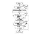
図2は、制御回路311,321の上記動作の具体的な一例を示すフローチャートである。まずステップST1にて、制御回路311,321は発電機が回生電力の出力を開始しているかどうかを判断する。これは、外部の装置(例えばエンジンECU)からの通知に基づいて判断されればよい。回生電力の出力を開始していないと判断したときには、制御回路311,321は再びステップST1を実行する。回生電力の出力を開始していると判断したときには、ステップST2にて、制御回路311はスイッチ41をオンし、オンの仮制御信号S31を出力する。次にステップST3にて制御回路321はスイッチ42をオンし、オンの仮制御信号S32を出力する。したがって制御信号S3により、分離スイッチ43がオンする。
FIG. 2 is a flowchart showing a specific example of the operation of the
なおステップST2,ST3の実行順序は逆でもよく、互いに並行して実行されてもよい。またステップST1の判断は、制御回路311,321の一方が行い、その判断結果を他方に通知してもよい。
The execution order of steps ST2 and ST3 may be reversed, or they may be executed in parallel with each other. The determination in step ST1 may be performed by one of the
<地絡>
以下では、電力系統に生じる地絡を考慮する。ここでいう電力系統とは、発電機1、蓄電装置21,22、スイッチ41,42、分離スイッチ43および車両負荷51,52を繋ぐ経路を示す。また以下では、分離スイッチ43よりも発電機1、蓄電装置21および車両負荷51側の電力系統を第1系統71とも呼び、分離スイッチ43よりも蓄電装置22および車両負荷52側の電力系統を第2系統72とも呼ぶ。スイッチ41は第1系統71に属し、スイッチ42は第2系統72に属する。分離スイッチ43は第1系統71と第2系統72とに間に接続されて、これらの導通/非導通を選択する。
<Ground fault>
In the following, ground faults occurring in the power system are considered. The power system referred to here indicates a path connecting the
第2系統72側に地絡が発生したときには、第2系統72を第1系統71から切り離すべく、制御回路311,321は、それぞれ分離スイッチ43をオフするための仮制御信号S31,S32を出力する。これにより、この地絡の第1系統71への影響を回避することができる。
When a ground fault occurs on the
また地絡が発生していない第1系統71を機能させるべく、制御回路311はスイッチ41をオンする。これにより、車両負荷51は蓄電装置21または発電機1によって給電されて、機能を発揮することができる。
Further, the
第2系統72では地絡が発生しているので、制御回路321はスイッチ42をオフしてもよい。蓄電装置22は車両負荷52へと給電できないからである。
Since a ground fault has occurred in the
第1系統71側に地絡が発生したときにも、第1系統71を第2系統72から切り離すべく、制御回路311,321は、それぞれ分離スイッチ43をオフするための仮制御信号S31,S32を出力する。これにより、この地絡の第2系統72への影響を回避することができる。
Even when a ground fault occurs on the
また地絡が発生していない第2系統72を機能させるべく、制御回路321はスイッチ42をオンする。これにより、車両負荷52は蓄電装置22によって給電されて、機能を発揮することができる。
Further, the
第1系統71では地絡が発生しているので、制御回路311はスイッチ41をオフしてもよい。蓄電装置21は車両負荷51へと給電できないからである。
Since a ground fault has occurred in the
次に地絡の検出について述べる。地絡は電圧または電流に基づいて検出される。図1の例示では、例えば地絡検出部として機能する、電圧検出回路313,323,332,333および電流検出回路314,324,334が設けられている。
Next, detection of a ground fault will be described. A ground fault is detected based on voltage or current. In the example of FIG. 1, for example,
電圧検出回路313は、例えばスイッチ41よりも蓄電装置21側において、蓄電装置21の端子電圧を検出し、検出した電圧を制御回路311へと出力する。電圧検出回路323は、例えばスイッチ42よりも蓄電装置22側において、蓄電装置22の端子電圧を検出し、検出した電圧を例えば制御回路321へと出力する。電圧検出回路332は、スイッチ41および分離スイッチ43の間の配線と、接地との間に印加される電圧を検出し、検出した電圧を制御回路311へと出力する。電圧検出回路333は、スイッチ42および分離スイッチ43の間の配線と、接地との間に印加される電圧を検出し、検出した電圧を例えば制御回路311へと出力する。
The
電流検出回路314は蓄電装置21を流れる電流を検出し、検出した電流を制御回路311へと出力する。図1の例示では、シャント抵抗315が設けられている。シャント抵抗315は、発電機1および車両負荷51の各々と蓄電装置21との間において、スイッチ41と直列に接続されている。電流検出回路314はシャント抵抗315の両端電圧を検出する。シャント抵抗315を流れる電流は、シャント抵抗315の両端電圧および抵抗値に基づいて算出できる。
電流検出回路324は蓄電装置22を流れる電流を検出し、検出した電流を制御回路321へと出力する。図1の例示では、シャント抵抗325が設けられている。シャント抵抗325は、分離スイッチ43および車両負荷52の各々と蓄電装置22との間において、スイッチ42と直列に接続されている。電流検出回路324はシャント抵抗325の両端電圧を検出する。シャント抵抗325を流れる電流は、シャント抵抗325の両端電圧および抵抗値に基づいて算出できる。
電流検出回路334は分離スイッチ43を流れる電流を検出し、検出した電流を制御回路311へと出力する。図1の例示では、シャント抵抗335が設けられている。シャント抵抗335は、発電機1、車両負荷51およびスイッチ41の各々と、車両負荷52およびスイッチ42の各々との間において、分離スイッチ43と直列に接続されている。電流検出回路334はシャント抵抗335の両端電圧を検出する。シャント抵抗335を流れる電流は、シャント抵抗335の両端電圧および抵抗値に基づいて算出できる。
The
地絡が発生すると、大きな電流(地絡電流)が発生したり、あるいは、電圧が低下するので、各電圧検出部または各電流検出部によって、地絡を検出できる。例えばスイッチ41,42および分離スイッチ43がオンしているときに、電圧検出回路313,323,332,333のいずれかによって検出される電圧が所定値よりも小さかったり、あるいは、電流検出回路314,324,334のいずれかによって検出される電流が所定値よりも大きいときに、地絡の発生を検出してもよい。これらの所定値は、それぞれ予め設定されて記憶媒体に記憶されていてもよい。
When a ground fault occurs, a large current (ground fault current) is generated or the voltage is reduced. Therefore, the ground fault can be detected by each voltage detecting unit or each current detecting unit. For example, when the
制御回路311,321は、この地絡の検出に応答して、それぞれ、分離スイッチ43をオフする仮制御信号S31,S32を出力する。上述のように、地絡が第1系統71に発生しても第2系統72に発生しても、分離スイッチ43をオフさせるためである。これにより、第1系統71と第2系統72とが分離される。
The
この状態において、例えば電圧検出回路313,332によって検出される電圧が所定値よりも小さかったり、あるいは、電流検出回路314によって検出される電流が所定値よりも大きいときには、第1系統71側において地絡が発生していると判断して、制御回路311はスイッチ41をオフする。
In this state, for example, when the voltage detected by the
あるいは、上記の状態において、例えば電圧検出回路323,333によって検出される電圧が所定値よりも小さかったり、あるいは、電流検出回路324によって検出される電流が所定値よりも大きいときには、第2系統72側において地絡が発生していると判断して、制御回路321はスイッチ42をオフする。
Alternatively, in the above state, for example, when the voltage detected by the
ところで、このような地絡発生時には、スイッチ41,42に比べて、分離スイッチ43をより確実にオフすることが望ましい。例えば第1系統71において地絡が発生したときには、たとえスイッチ41をオフできなくても、分離スイッチ43さえオフできれば、当該地絡の第2系統72への影響を回避することができる。これにより、第2系統72において蓄電装置22から車両負荷52へと電力を供給できる。なお例えば第1系統71において蓄電装置21とスイッチ41との間に地絡が生じている場合には、スイッチ41をオフできれば、当該地絡の第2系統72への影響を回避できる。しかしながら、スイッチ41に対して蓄電装置21とは反対側で地絡が発生しているときにはスイッチ41をオフしても地絡と第2系統72側との遮断を行えないが、分離スイッチ43をオフすれば当該遮断が実現される。つまり第1系統71における地絡がスイッチ41に対して蓄電装置21側で発生しても、蓄電装置21と反対側で発生しても、またスイッチ41の動作の良否に拘わらず、分離スイッチ43のオフによって上記遮断を実現できる。
By the way, when such a ground fault occurs, it is desirable to turn off the
同様に、第2系統72に地絡が生じている場合、仮にスイッチ42をオフできなくても、分離スイッチ43さえオフできれば、当該地絡の第1系統71側への影響を回避できる。したがって、スイッチ41,42のオフに優先して、分離スイッチ43を確実にオフすることが望ましい。
Similarly, when a ground fault occurs in the
そこで、本スイッチ装置10では、制御回路311,321および論理回路11が設けられている。これにより、たとえ制御回路311,321の一方が誤動作によって、分離スイッチ43のオンを維持しようとしても、他方が分離スイッチ43をオフすることができる。例えば、制御回路311が誤動作により、オンの仮制御信号S31を出力しても、制御回路321が適切にオフの仮制御信号S32を出力することで、論理回路11はオフの制御信号S3を出力する。これにより、分離スイッチ43をより確実にオフすることができる。
Therefore, in the
一方で上述のように、制御回路311,321は互いに独立してスイッチ41,42を制御する。つまり、制御回路311は制御回路321とは独立してスイッチ41を制御し、制御回路321は制御回路311とは独立してスイッチ42を制御する。よって、スイッチ41,42を、制御回路311,321によって制御する構造に比して、制御回路311,321の処理を簡易にできる。また論理回路が不要になるので、製造コストおよび回路規模を低減することができる。
On the other hand, as described above, the
図3は、制御回路311,321の動作の一例を示すフローチャートである。ステップST11にて、制御回路311,321は、それぞれ地絡が発生したか否かを判断する。なお制御回路311,321は判断結果を互いに送信するとよい。これにより、制御回路311,321が異なる箇所の地絡を検出する場合であっても、制御回路311,321は地絡の発生を認識することができる。
FIG. 3 is a flowchart illustrating an example of the operation of the
地絡が発生したと判断したときには、ステップST12にて、制御回路311,321はオフの仮制御信号S31,S32をそれぞれ出力する。次にステップST13にて、制御回路311は、第1系統71において地絡が発生しているか否かを判断する。第1系統71に地絡が発生していると判断したときには、ステップST14にて、制御回路311はスイッチ41をオフする。ステップST14の次、または、ステップST13にて第1系統71に地絡が発生していないと判断したときには、ステップST15にて、制御回路321は、第2系統72に地絡が発生しているか否かを判断する。第2系統72に地絡が発生したと判断したときには、制御回路321はスイッチ42をオフする。第2系統72において地絡が発生していないと判断したときには、ステップST16を実行することなく処理を終了する。
When it is determined that a ground fault has occurred, in step ST12, the
なおステップST13,ST14の一組とステップST15,ST16の一組との実行順序は逆であってもよい。またステップST12は、必ずしもステップST11,ST13の間で実行される必要はなく、ステップST11において肯定的な判断がなされた時点よりも後に実行されればよい。 The execution order of one set of steps ST13 and ST14 and one set of steps ST15 and ST16 may be reversed. Step ST12 does not necessarily have to be executed between steps ST11 and ST13, and may be executed after the time when a positive determination is made in step ST11.
なお、第1系統71の地絡が、スイッチ41よりも蓄電装置21側で発生しているときには、制御回路311がスイッチ41をオフすれば、分離スイッチ43をオンしても、当該地絡の蓄電装置22への影響を回避することができる。つまり、第1系統71の地絡による第2系統72への影響を回避するために、分離スイッチ43をより確実にオフすることが望まれるものの、スイッチ41のオフによって、当該地絡の第2系統72への影響を回避できる場合には、分離スイッチ43をオンしてもよいのである。よってこのとき、制御回路311,321は、分離スイッチ43をオンする仮制御信号S31,S32を出力してもよい。これによれば、蓄電装置22が車両負荷51,52へと給電することができる。以下に具体的な処理の一例を説明する。
When the ground fault of the
例えば第1系統71の地絡に応答して、スイッチ41および分離スイッチ43をオフした状態で、制御回路311,321は、分離スイッチ43を再びオンすべく、仮制御信号S31,S32をそれぞれ出力する。もし地絡がスイッチ41よりも発電機1または車両負荷51側に発生していれば、蓄電装置22からスイッチ42および分離スイッチ43を経由して、地絡電流が流れる。逆に言えば、この状態で、蓄電装置22を流れる電流が所定値よりも小さいときには、スイッチ41よりも蓄電装置21側に地絡が生じていると判断することができる。よって、当該電流が所定値よりも小さいときには、分離スイッチ43をオンに維持する。これにより、蓄電装置22は車両負荷51へも給電できる。その一方で、当該電流が所定値よりも大きいときには、制御回路311,321は、分離スイッチ43をターンオフすべく、仮制御信号S31,S32をそれぞれ出力する。これにより、当該地絡の蓄電装置22への影響を回避することができる。
For example, in response to a ground fault of the
なおスイッチ41よりも蓄電装置21側に地絡が生じたと判断したときに、制御回路311が暴走してスイッチ41をオンしたとしても、制御回路321が単独で分離スイッチ43をオフできる。よってこの場合でも、当該地絡の第2系統72への影響を回避することができる。なお制御回路321は、例えば制御回路311から適切に信号を受信しないことにより、制御回路311の暴走を認識できる。
Note that when it is determined that a ground fault has occurred on the
また第2系統72において、スイッチ42よりも蓄電装置22側に地絡が発生したときにも同様に処理できる。つまり、このとき制御回路311がスイッチ42をオフすれば、分離スイッチ43をオンしても、当該地絡の蓄電装置21への影響を回避することができるので、制御回路311,321は、分離スイッチ43をオンする仮制御信号S31,S32を出力してもよい。これにより、発電機1または蓄電装置21は車両負荷51のみならず、車両負荷52へも給電できる。
Also, in the
車両負荷51,52が同一機能を有している場合には、車両負荷51,52の両方に電力を供給することにより、車両負荷51,52の機能冗長を実現できる。 When the vehicle loads 51 and 52 have the same function, by supplying power to both the vehicle loads 51 and 52, functional redundancy of the vehicle loads 51 and 52 can be realized.
<制御回路の電源>
図1の例示では、制御回路311は電源回路312から電力を受け取って動作する。電源回路312は、例えばその入力側において、それぞれダイオードD11,D21を介して蓄電装置21,22に接続されている。ダイオードD11の順方向は、蓄電装置21から電源回路312へと電流が流れる方向であり、ダイオードD21の順方向は、蓄電装置22から電源回路312へと電流が流れる方向である。ダイオードD11の順方向とダイオードD21の順方向とは電源回路312から見て同じ方向であって、ダイオードD11,D21は、蓄電装置21,22間の電流の回り込みを回避する。電源回路312は、入力された電圧を制御回路311の動作電圧として適した電圧に変換し、当該電圧を出力する。電源回路312は例えばスイッチングレギュレータである。
<Power supply for control circuit>
In the example of FIG. 1, the
制御回路321も、制御回路311と同様に、電源回路322から電力を受け取って動作する。電源回路322は、例えばその入力側において、それぞれダイオードD12,D22を介して蓄電装置21,22に接続されている。ダイオードD12の順方向は、蓄電装置21から電源回路322へと電流が流れる方向であり、ダイオードD22の順方向は、蓄電装置22から電源回路322へと電流が流れる方向である。ダイオードD12の順方向とダイオードD22の順方向とは電源回路322から見て同じ方向であって、ダイオードD12,D22は蓄電装置21,22間の電流の回り込みを回避する。電源回路322は、入力された電圧を制御回路321の動作電圧として適した電圧に変換して、当該電圧を出力する。電源回路322は例えばスイッチングレギュレータである。
The
このような構成によれば、蓄電装置21,22の一方が消失しても、他方が制御回路311,321へと電源を供給することができる。
According to such a configuration, even if one of
<スイッチ装置>
スイッチ装置10は例えばパッケージを備えている。このパッケージには、スイッチ装置10が備える上述の構成の全てを収納していてもよい。これにより、スイッチ装置10を一体で取り扱うことができ、スイッチ装置10の取り付けが容易である。またスイッチ装置10が備える上述の全ての構成は、所定の基板上に実装されていてもよい。
<Switch device>
The
<車両>
図4は、車載電源システム100の構成の一例を示すブロック図である。図4の例示では、車載電源システム100は車両200に搭載されている。車両200には、例えばエンジンルーム210、車室220およびラゲッジルーム230が設けられている。ラゲッジルーム230は車室220に対してエンジンルーム210とは反対側に設けられる。エンジンルーム210は例えば車両200の進行方向の前方に設けられている。
<Vehicle>
FIG. 4 is a block diagram showing an example of the configuration of the vehicle-mounted
図4の例示では、蓄電装置21、スイッチ装置10および発電機1は、エンジンルーム210に配置されている。また蓄電装置22はラゲッジルーム230側に配置されている。車両負荷51,52は例えば車室220側に配置されている。
In the example of FIG. 4,
<スイッチ制御の例>
以下、スイッチ41,42および分離スイッチ43の制御の例について述べる。
<Example of switch control>
Hereinafter, an example of control of the
<力行時および駐車時>
制御回路311,321は、車両の力行時または駐車時には、それぞれスイッチ41,42をオンする。車両が力行していることは、例えばエンジンECUから制御回路311,321へと通知されてもよい。なおここでいう力行とは、例えば、アクセル開度が初期値よりも大きい状態での車両の走行をいう。また、車両が駐車していることは、例えばエンジンECUからエンジンの停止の通知に基づいて判断してもよい。
<When running and parking>
The
車両の力行時または駐車時において、スイッチ41,42がオンするので、このとき車両負荷51,52には電力が供給される。よって車両負荷51,52の機能冗長が実現できる。また制御回路311,321は分離スイッチ43をオンしてもよく、オフしてもよい。分離スイッチ43がオンしているときには、発電機1および蓄電装置21,22が車両負荷51,52に電源を供給できる。
Since the
分離スイッチ43がオフしているときには、車両負荷51は蓄電装置21から給電され、車両負荷52は蓄電装置22から給電される。つまり、第1系統71および第2系統72が互いに独立した状態で、車両負荷51,52へ給電できる。またこの状態で第1系統71および第2系統72の一方に地絡が生じたときには、地絡発生の判断を待つことなく、当該地絡の、他方の系統への影響を回避できる。もし分離スイッチ43がオンしていると、地絡が発生してから分離スイッチ43がオフするまでの期間において、車両負荷51,52への給電に不備が生じることが考えられる。力行時または駐車時に分離スイッチ43がオフしていると、たとえ第1系統71および第2系統72の一方に地絡が発生しても、他方の系統において、車両負荷へ安定的に給電できるのである。
When separation switch 43 is off,
図5は、制御回路311,321の上記動作の一例を示すフローチャートである。ステップST21にて、制御回路311,321は、車両が力行しているか、駐車しているかを判断する。この判断は例えば外部の装置(例えばエンジンECU)からの通知に基づいて行うことができる。否定的な判断がなされると、制御回路311,321は再びステップST21を実行する。
FIG. 5 is a flowchart showing an example of the operation of the
肯定的な判断がなされると、ステップST22にて、制御回路311はスイッチ41をオンし、オフの仮制御信号S31を出力する。次にステップST23にて、制御回路321はスイッチ42をオンし、オフの仮制御信号S32を出力する。なおステップST22,ST23の実行順序は逆であってもよく、あるいは、ステップST22,ST23が並行して実行されてもよい。
If an affirmative determination is made, in step ST22, the
<スイッチ>
例えば、スイッチ41,42はノーマリオン型のスイッチであり、分離スイッチ43はノーマリオフ型のスイッチであってもよい。これによれば、例えば駐車時に、制御回路311,321が動作を停止しても、スイッチ41,42をオンでき、分離スイッチ43をオフできる。したがって、駐車時における消費電力を低減することができる。
<Switch>
For example, the
<蓄電装置の充電率の算出>
<開放電圧に基づく充電率の算出>
スイッチ41をオフしたときに電圧検出回路313によって検出される蓄電装置21の端子電圧は、蓄電装置21の開放電圧とみなすことができる。制御回路311はこの開放電圧に基づいて蓄電装置21の充電率を算出してもよい。開放電圧と充電率との関係は例えば予め設定されて、記憶媒体に記憶されていてもよい。開放電圧と充電率との関係はほぼ正確に予め求めることができるので、制御回路311は蓄電装置21の充電率を高い精度で求めることができる。以下、この算出を高精度算出とも呼ぶ。
<Calculation of charging rate of power storage device>
<Calculation of charging rate based on open circuit voltage>
The terminal voltage of the
なおスイッチ41をオフしているときには、車両負荷51,52への電力の供給を維持すべく、スイッチ42および分離スイッチ43をオンすることが望ましい。つまり、高精度算出を行うときには、スイッチ42および分離スイッチ43をオンすることが望ましい。
When the
図6は、蓄電装置21の充電率を算出するときの、制御回路311,321の動作の一例を示すフローチャートである。まずステップST31にて、制御回路311はスイッチ41をオフし、制御回路321はスイッチ42をオンし、制御回路311,321は、それぞれオンの仮制御信号S31,S32を出力する。これにより、分離スイッチ43はオンする。次にステップST32にて、電圧検出回路313は蓄電装置21の端子電圧を開放電圧として検出し、これを制御回路311へと出力する。次にステップST33にて、制御回路311は開放電圧に基づいて蓄電装置21の充電率を算出する。なお、開放電圧を検出した後には、制御回路311,321は、スイッチ41,42および分離スイッチ43を、ステップST31の前の状態に戻してもよい。
FIG. 6 is a flowchart illustrating an example of the operation of the
<電流に基づく充電率の算出>
上記高精度算出方法では、蓄電装置21の開放電圧を検出するためにスイッチ41をオフする必要がある。よって、蓄電装置21からの給電を行うことができない。そこで、スイッチ41をオンしているときには、高精度算出において算出された充電率を用いた以下の方法によって蓄電装置21の充電率を算出してもよい。つまり一旦はスイッチ41をオフして高精度算出により充電率を求めた上で、スイッチ41をオンし、以下のように充電率を算出する。
<Calculation of charging rate based on current>
In the high-precision calculation method, the
例えば制御回路311は、スイッチ41をオンしているときには、蓄電装置21を流れる電流を、電流検出回路314を用いて検出し、開放電圧に基づいて算出された上記の充電率と、検出した電流の積算とに基づいて、公知の手法により、蓄電装置21の充電率を算出してもよい。この算出方法は、高精度算出に比べて、充電率の算出精度は低いものの、スイッチ41をオンできるので、蓄電装置21を車両負荷51の電源として機能させることができる。以下では、電流の積算に基づく算出を、低精度算出とも呼ぶ。
For example, when the
制御回路311は、高精度算出と低精度算出とを繰り返し行ってもよい。例えば低精度算出を複数回行うたびに、高精度算出を行ってもよい。また低精度算出では、直近の高精度算出を用いて算出された充電率と、電流の積算とに基づいて、充電率を算出するとよい。これによれば、複数回の低精度算出の度に生じる誤差を、高精度算出の度に低減することができる。
The
なお上述の例では、蓄電装置21の充電率について述べたものの、蓄電装置22でも同様である。つまり、スイッチ41と分離スイッチ43とをオンしつつ、スイッチ42をオフした状態で、蓄電装置22の端子電圧を開放電圧として検出し、この開放電圧に基づいて蓄電装置22の充電率を算出する。これにより、高精度に蓄電装置22の充電率を算出できる。
Note that, in the above example, the charging rate of the
一方で、スイッチ41をオンしているときには、蓄電装置22を流れる電流と、開放電圧に基づいた算出した充電率とを用いて、蓄電装置22の充電率を算出する。蓄電装置22においても、高精度算出と低精度算出とを繰り返し実行してもよい。
On the other hand, when the
上記各実施形態及び各変形例で説明した各構成は、相互に矛盾しない限り適宜組み合わせることができる。 The configurations described in the above embodiments and modifications can be appropriately combined as long as they do not conflict with each other.
以上のようにこの発明は詳細に説明されたが、上記した説明は、すべての局面において、例示であって、この発明がそれに限定されるものではない。例示されていない無数の変形例が、この発明の範囲から外れることなく想定され得るものと解される。 Although the present invention has been described in detail as described above, the above description is merely an example in all aspects, and the present invention is not limited thereto. It is understood that innumerable modifications that are not illustrated can be assumed without departing from the scope of the present invention.
10 車載電源用のスイッチ装置
11 論理回路
21,22 蓄電装置(第1蓄電装置および第2蓄電装置)
41,42 スイッチ(第1スイッチおよび第2スイッチ)
43 分離スイッチ
51,52 車両負荷(第1車両負荷および第2車輌負荷)
71 第1系統
72 第2系統
311,321 制御回路(第1制御回路および第2制御回路)
313 電圧検出回路
S31,S32 仮制御信号(第1仮制御信号および第2仮制御信号)
41, 42 switches (first switch and second switch)
43
71
313 Voltage detection circuit S31, S32 Temporary control signal (first temporary control signal and second temporary control signal)
Claims (6)
前記分離スイッチのオン/オフを制御するための第1仮制御信号を出力する第1制御回路と、
前記分離スイッチのオン/オフを制御するための第2仮制御信号を出力する第2制御回路と、
前記第1仮制御信号および前記第2仮制御信号の少なくともいずれか一方がオフを示すときに前記分離スイッチをオフし、前記第1仮制御信号および前記第2仮制御信号のいずれもがオンを示すときに前記分離スイッチをオンする論理回路と、
前記発電機および前記第1車両負荷の各々と、前記第1蓄電装置との間に接続され、前記第1制御回路によってオン/オフが制御される第1スイッチと、
前記第2車両負荷と前記第2蓄電装置との間に接続され、前記第2制御回路によってオン/オフが制御される第2スイッチと
を備え、
前記第1制御回路および前記第2制御回路は、前記発電機の発電の開始に応じて、オンを示す前記第1仮制御信号および前記第2仮制御信号を出力し、前記第1系統または前記第2系統に地絡が生じたと判断したときには、オフを示す前記第1仮制御信号および前記第2仮制御信号を出力する、車載電源用のスイッチ装置。 A first system including at least a generator that generates power during regeneration of the vehicle, a first power storage device charged by the generator, and a first vehicle load supplied from the first power storage device; and a second power storage device. A separation switch connected to a second system including a second vehicle load fed from the second power storage device;
A first control circuit that outputs a first temporary control signal for controlling on / off of the separation switch;
A second control circuit that outputs a second temporary control signal for controlling on / off of the separation switch;
When at least one of the first temporary control signal and the second temporary control signal indicates off, the separation switch is turned off, and both the first temporary control signal and the second temporary control signal are turned on. A logic circuit for turning on the separation switch when indicated ,
A first switch that is connected between each of the generator and the first vehicle load and the first power storage device and that is turned on / off by the first control circuit;
A second switch that is connected between the second vehicle load and the second power storage device and that is turned on / off by the second control circuit ;
The first control circuit and the second control circuit output the first temporary control signal and the second temporary control signal indicating ON in response to the start of power generation of the generator, and the first system or the second system A switch device for an in-vehicle power supply that outputs the first temporary control signal and the second temporary control signal indicating off when it is determined that a ground fault has occurred in a second system.
前記第1スイッチよりも前記第1蓄電装置側において、前記第1蓄電装置の端子電圧を検出する電圧検出回路を更に備え、
前記第1スイッチがオフし、前記第2スイッチがオンし、前記分離スイッチがオンした状態で、前記第1制御回路は、前記端子電圧に基づいて前記第1蓄電装置の充電率を求める、車載電源用のスイッチ装置。 A switch device for a vehicle-mounted power supply according to claim 1 ,
A voltage detection circuit that detects a terminal voltage of the first power storage device on the side of the first power storage device with respect to the first switch;
In a state where the first switch is turned off, the second switch is turned on, and the separation switch is turned on, the first control circuit obtains a charging rate of the first power storage device based on the terminal voltage. Switch device for power supply.
前記車両の力行中および駐車中に、
前記第1制御回路は、前記第1スイッチをオンし、オフを示す前記第1仮制御信号を出力し、
前記第2制御回路は、前記第2スイッチをオンし、オフを示す前記第2仮制御信号を出力する、車載電源用のスイッチ装置。 A switch device for a vehicle-mounted power supply according to claim 1 or 2 ,
During power running and parking of the vehicle,
The first control circuit turns on the first switch and outputs the first temporary control signal indicating off;
The switch device for a vehicle-mounted power supply, wherein the second control circuit turns on the second switch and outputs the second temporary control signal indicating off.
前記第1スイッチおよび前記第2スイッチはノーマリオン型のスイッチであり、前記分離スイッチはノーマリオフ型のスイッチである、車載電源用のスイッチ装置。 A switch device for an in-vehicle power supply according to any one of claims 1 to 3 , wherein
The switch device for a vehicle-mounted power supply, wherein the first switch and the second switch are normally-on switches, and the separation switch is a normally-off switch.
前記分離スイッチ、前記第1制御回路、前記第2制御回路および前記論理回路を収納するパッケージを備える、車載電源用のスイッチ装置。 A switch device for a vehicle-mounted power supply according to any one of claims 1 to 4 , wherein:
A switch device for a vehicle-mounted power supply, comprising: a package containing the separation switch, the first control circuit, the second control circuit, and the logic circuit.
前記発電機および前記第1車両負荷の各々と、前記第1蓄電装置との間に接続される第1スイッチと、
前記第2車両負荷と前記第2蓄電装置との間に接続される第2スイッチと
を備える車載電源用のスイッチ装置を制御する装置であって、
前記分離スイッチのオン/オフを制御するための第1仮制御信号を出力する第1制御回路と、
前記分離スイッチのオン/オフを制御するための第2仮制御信号を出力する第2制御回路と、
前記第1仮制御信号および前記第2仮制御信号の少なくともいずれか一方がオフを示すときに、前記分離スイッチをオフし、前記第1仮制御信号および前記第2仮制御信号のいずれもがオンを示すときに、前記分離スイッチをオンする論理回路と
を備え、
前記第1制御回路および前記第2制御回路は、前記発電機の発電の開始に応じて、オンを示す前記第1仮制御信号および前記第2仮制御信号を出力し、前記第1系統または前記第2系統に地絡が生じたと判断したときには、オフを示す前記第1仮制御信号および前記第2仮制御信号を出力し、
前記第1制御回路は、前記第1スイッチのオン/オフを制御し、
前記第2制御回路は、前記第2スイッチのオン/オフを制御する、制御装置。 A first system including at least a generator that generates power during regeneration of the vehicle, a first power storage device charged by the generator, and a first vehicle load supplied from the first power storage device; and a second power storage device. A separation switch connected to a second system including a second vehicle load fed from the second power storage device ;
A first switch connected between each of the generator and the first vehicle load, and the first power storage device;
A second switch connected between the second vehicle load and the second power storage device, for controlling a switch device for a vehicle-mounted power supply,
A first control circuit that outputs a first temporary control signal for controlling on / off of the separation switch;
A second control circuit that outputs a second temporary control signal for controlling on / off of the separation switch;
When at least one of the first temporary control signal and the second temporary control signal indicates OFF, the separation switch is turned off, and both the first temporary control signal and the second temporary control signal are turned on. And a logic circuit for turning on the separation switch,
The first control circuit and the second control circuit output the first temporary control signal and the second temporary control signal indicating ON in response to the start of power generation of the generator, and the first system or the second system When it is determined that a ground fault has occurred in the second system, the first temporary control signal and the second temporary control signal indicating OFF are output ,
The first control circuit controls on / off of the first switch,
The control device , wherein the second control circuit controls on / off of the second switch .
Priority Applications (4)
| Application Number | Priority Date | Filing Date | Title |
|---|---|---|---|
| JP2016067383A JP6651941B2 (en) | 2016-03-30 | 2016-03-30 | Switch device and control device for vehicle power supply |
| US15/779,117 US10601215B2 (en) | 2016-03-30 | 2017-03-16 | On-vehicle power source switch apparatus and control apparatus |
| PCT/JP2017/010557 WO2017169817A1 (en) | 2016-03-30 | 2017-03-16 | On-vehicle power source switch apparatus and control apparatus |
| CN201780002337.8A CN107949972B (en) | 2016-03-30 | 2017-03-16 | Switching device and control device for vehicle-mounted power supply |
Applications Claiming Priority (1)
| Application Number | Priority Date | Filing Date | Title |
|---|---|---|---|
| JP2016067383A JP6651941B2 (en) | 2016-03-30 | 2016-03-30 | Switch device and control device for vehicle power supply |
Publications (3)
| Publication Number | Publication Date |
|---|---|
| JP2017184428A JP2017184428A (en) | 2017-10-05 |
| JP2017184428A5 JP2017184428A5 (en) | 2018-02-08 |
| JP6651941B2 true JP6651941B2 (en) | 2020-02-19 |
Family
ID=59965413
Family Applications (1)
| Application Number | Title | Priority Date | Filing Date |
|---|---|---|---|
| JP2016067383A Active JP6651941B2 (en) | 2016-03-30 | 2016-03-30 | Switch device and control device for vehicle power supply |
Country Status (4)
| Country | Link |
|---|---|
| US (1) | US10601215B2 (en) |
| JP (1) | JP6651941B2 (en) |
| CN (1) | CN107949972B (en) |
| WO (1) | WO2017169817A1 (en) |
Families Citing this family (14)
| Publication number | Priority date | Publication date | Assignee | Title |
|---|---|---|---|---|
| JP6540565B2 (en) * | 2016-03-16 | 2019-07-10 | 株式会社オートネットワーク技術研究所 | Power supply system for vehicle, drive system for vehicle |
| JP6671223B2 (en) * | 2016-04-12 | 2020-03-25 | ヤマハ発動機株式会社 | Ship power supply system |
| JP2018182864A (en) * | 2017-04-10 | 2018-11-15 | 株式会社デンソー | Power control device and power control method |
| TWI644495B (en) * | 2017-11-24 | 2018-12-11 | 和碩聯合科技股份有限公司 | Input protection circuit |
| US11059384B2 (en) * | 2018-08-09 | 2021-07-13 | Ford Global Technologies, Llc | Power distribution system for vehicle lighting |
| JP2020053176A (en) * | 2018-09-25 | 2020-04-02 | 株式会社デンソー | Battery monitoring system |
| CN111169412B (en) * | 2018-11-09 | 2023-01-10 | 联发科技(新加坡)私人有限公司 | Vehicle-mounted terminal and startup and shutdown method |
| JP7205343B2 (en) * | 2019-03-27 | 2023-01-17 | 株式会社デンソー | Mobile power supply system |
| JP7055777B2 (en) * | 2019-07-12 | 2022-04-18 | 矢崎総業株式会社 | Detection device |
| GB2590458A (en) * | 2019-12-19 | 2021-06-30 | Dyson Technology Ltd | Electric vehicle power system bus management |
| JP6990732B2 (en) * | 2020-03-17 | 2022-01-12 | 本田技研工業株式会社 | Power supply device and vehicle |
| WO2023138847A1 (en) | 2022-01-20 | 2023-07-27 | Volkswagen Aktiengesellschaft | Low-voltage supply assembly for an automated or semi-automated vehicle, and method for operating a semi-automated or automated vehicle |
| DE102022200880B4 (en) | 2022-01-20 | 2024-02-01 | Volkswagen Aktiengesellschaft | Low-voltage supply arrangement for an automated or partially automated vehicle and method for operating a partially automated or partially automated vehicle |
| WO2024013961A1 (en) * | 2022-07-15 | 2024-01-18 | 日産自動車株式会社 | Method and device for controlling vehicle |
Family Cites Families (9)
| Publication number | Priority date | Publication date | Assignee | Title |
|---|---|---|---|---|
| JPS60148326A (en) * | 1984-01-10 | 1985-08-05 | 富士電機株式会社 | Protective relay system |
| JP2008211891A (en) * | 2007-02-26 | 2008-09-11 | Hitachi Ltd | Digital protection relay |
| US8437910B2 (en) * | 2009-10-16 | 2013-05-07 | Mitsubishi Electric Corporation | Automotive electric power supply system |
| EP2477040A4 (en) * | 2010-10-08 | 2014-08-13 | Sanyo Electric Co | Ground fault detection circuit, and ground fault detection device |
| JP5477409B2 (en) * | 2012-03-12 | 2014-04-23 | 株式会社デンソー | Power system |
| JP6111967B2 (en) * | 2013-10-08 | 2017-04-12 | 株式会社オートネットワーク技術研究所 | Power system |
| JP6107591B2 (en) * | 2013-10-18 | 2017-04-05 | 株式会社オートネットワーク技術研究所 | Vehicle power system |
| CN106458118B (en) * | 2014-05-12 | 2018-09-28 | 株式会社自动网络技术研究所 | The supply unit of motor vehicle |
| JP2017061240A (en) * | 2015-09-25 | 2017-03-30 | 株式会社オートネットワーク技術研究所 | On-vehicle power supply device and method for control thereof |
-
2016
- 2016-03-30 JP JP2016067383A patent/JP6651941B2/en active Active
-
2017
- 2017-03-16 CN CN201780002337.8A patent/CN107949972B/en active Active
- 2017-03-16 US US15/779,117 patent/US10601215B2/en active Active
- 2017-03-16 WO PCT/JP2017/010557 patent/WO2017169817A1/en active Application Filing
Also Published As
| Publication number | Publication date |
|---|---|
| JP2017184428A (en) | 2017-10-05 |
| CN107949972B (en) | 2020-12-04 |
| US10601215B2 (en) | 2020-03-24 |
| WO2017169817A1 (en) | 2017-10-05 |
| US20190013664A1 (en) | 2019-01-10 |
| CN107949972A (en) | 2018-04-20 |
Similar Documents
| Publication | Publication Date | Title |
|---|---|---|
| JP6651941B2 (en) | Switch device and control device for vehicle power supply | |
| US11465574B2 (en) | Power supply system | |
| CN108602478B (en) | Switching device for vehicle-mounted power supply and vehicle-mounted power supply device | |
| WO2015015743A1 (en) | Vehicular power source system | |
| JP6662178B2 (en) | Switch device for in-vehicle power supply | |
| JP6215221B2 (en) | Vehicle power supply | |
| JP6312597B2 (en) | Vehicle power supply | |
| JP6597358B2 (en) | Switch device and power supply device for in-vehicle power supply | |
| US10407003B2 (en) | Short-circuit protection for vehicle redundant power architecture | |
| US10730391B2 (en) | Control of redundant power architecture for a vehicle | |
| KR20220026873A (en) | Power control apparatus and method for autonomous vehicle | |
| JP6446325B2 (en) | Power supply device | |
| JP2018062253A (en) | Backup device for vehicle | |
| JP2018061304A (en) | Backup device for vehicle | |
| WO2018012302A1 (en) | Power supply device | |
| JP6673179B2 (en) | Battery unit and power supply system | |
| WO2018110243A1 (en) | Battery unit, and power supply system | |
| JP6541414B2 (en) | Power supply device | |
| CN108698548B (en) | Charge rate monitoring device for vehicle-mounted power supply and vehicle-mounted power supply system | |
| JP7226273B2 (en) | Abnormality determination device | |
| WO2017175575A1 (en) | Switch device for on-vehicle power supply and on-vehicle power supply system |
Legal Events
| Date | Code | Title | Description |
|---|---|---|---|
| A521 | Request for written amendment filed |
Free format text: JAPANESE INTERMEDIATE CODE: A523 Effective date: 20171220 |
|
| A621 | Written request for application examination |
Free format text: JAPANESE INTERMEDIATE CODE: A621 Effective date: 20180628 |
|
| A131 | Notification of reasons for refusal |
Free format text: JAPANESE INTERMEDIATE CODE: A131 Effective date: 20190730 |
|
| A521 | Request for written amendment filed |
Free format text: JAPANESE INTERMEDIATE CODE: A523 Effective date: 20190904 |
|
| TRDD | Decision of grant or rejection written | ||
| A01 | Written decision to grant a patent or to grant a registration (utility model) |
Free format text: JAPANESE INTERMEDIATE CODE: A01 Effective date: 20191224 |
|
| A61 | First payment of annual fees (during grant procedure) |
Free format text: JAPANESE INTERMEDIATE CODE: A61 Effective date: 20200106 |
|
| R150 | Certificate of patent or registration of utility model |
Ref document number: 6651941 Country of ref document: JP Free format text: JAPANESE INTERMEDIATE CODE: R150 |