CN108602478B - Switching device for vehicle-mounted power supply and vehicle-mounted power supply device - Google Patents
Switching device for vehicle-mounted power supply and vehicle-mounted power supply device Download PDFInfo
- Publication number
- CN108602478B CN108602478B CN201780008701.1A CN201780008701A CN108602478B CN 108602478 B CN108602478 B CN 108602478B CN 201780008701 A CN201780008701 A CN 201780008701A CN 108602478 B CN108602478 B CN 108602478B
- Authority
- CN
- China
- Prior art keywords
- switch
- storage device
- power storage
- control circuit
- power supply
- Prior art date
- Legal status (The legal status is an assumption and is not a legal conclusion. Google has not performed a legal analysis and makes no representation as to the accuracy of the status listed.)
- Active
Links
Images


Classifications
-
- B—PERFORMING OPERATIONS; TRANSPORTING
- B60—VEHICLES IN GENERAL
- B60R—VEHICLES, VEHICLE FITTINGS, OR VEHICLE PARTS, NOT OTHERWISE PROVIDED FOR
- B60R16/00—Electric or fluid circuits specially adapted for vehicles and not otherwise provided for; Arrangement of elements of electric or fluid circuits specially adapted for vehicles and not otherwise provided for
- B60R16/02—Electric or fluid circuits specially adapted for vehicles and not otherwise provided for; Arrangement of elements of electric or fluid circuits specially adapted for vehicles and not otherwise provided for electric constitutive elements
- B60R16/03—Electric or fluid circuits specially adapted for vehicles and not otherwise provided for; Arrangement of elements of electric or fluid circuits specially adapted for vehicles and not otherwise provided for electric constitutive elements for supply of electrical power to vehicle subsystems or for
- B60R16/033—Electric or fluid circuits specially adapted for vehicles and not otherwise provided for; Arrangement of elements of electric or fluid circuits specially adapted for vehicles and not otherwise provided for electric constitutive elements for supply of electrical power to vehicle subsystems or for characterised by the use of electrical cells or batteries
-
- H—ELECTRICITY
- H02—GENERATION; CONVERSION OR DISTRIBUTION OF ELECTRIC POWER
- H02H—EMERGENCY PROTECTIVE CIRCUIT ARRANGEMENTS
- H02H3/00—Emergency protective circuit arrangements for automatic disconnection directly responsive to an undesired change from normal electric working condition with or without subsequent reconnection ; integrated protection
- H02H3/02—Details
- H02H3/021—Details concerning the disconnection itself, e.g. at a particular instant, particularly at zero value of current, disconnection in a predetermined order
-
- H—ELECTRICITY
- H02—GENERATION; CONVERSION OR DISTRIBUTION OF ELECTRIC POWER
- H02H—EMERGENCY PROTECTIVE CIRCUIT ARRANGEMENTS
- H02H3/00—Emergency protective circuit arrangements for automatic disconnection directly responsive to an undesired change from normal electric working condition with or without subsequent reconnection ; integrated protection
- H02H3/02—Details
- H02H3/05—Details with means for increasing reliability, e.g. redundancy arrangements
-
- H—ELECTRICITY
- H02—GENERATION; CONVERSION OR DISTRIBUTION OF ELECTRIC POWER
- H02H—EMERGENCY PROTECTIVE CIRCUIT ARRANGEMENTS
- H02H3/00—Emergency protective circuit arrangements for automatic disconnection directly responsive to an undesired change from normal electric working condition with or without subsequent reconnection ; integrated protection
- H02H3/16—Emergency protective circuit arrangements for automatic disconnection directly responsive to an undesired change from normal electric working condition with or without subsequent reconnection ; integrated protection responsive to fault current to earth, frame or mass
-
- H—ELECTRICITY
- H02—GENERATION; CONVERSION OR DISTRIBUTION OF ELECTRIC POWER
- H02H—EMERGENCY PROTECTIVE CIRCUIT ARRANGEMENTS
- H02H7/00—Emergency protective circuit arrangements specially adapted for specific types of electric machines or apparatus or for sectionalised protection of cable or line systems, and effecting automatic switching in the event of an undesired change from normal working conditions
- H02H7/10—Emergency protective circuit arrangements specially adapted for specific types of electric machines or apparatus or for sectionalised protection of cable or line systems, and effecting automatic switching in the event of an undesired change from normal working conditions for converters; for rectifiers
- H02H7/12—Emergency protective circuit arrangements specially adapted for specific types of electric machines or apparatus or for sectionalised protection of cable or line systems, and effecting automatic switching in the event of an undesired change from normal working conditions for converters; for rectifiers for static converters or rectifiers
- H02H7/1203—Circuits independent of the type of conversion
-
- H—ELECTRICITY
- H02—GENERATION; CONVERSION OR DISTRIBUTION OF ELECTRIC POWER
- H02H—EMERGENCY PROTECTIVE CIRCUIT ARRANGEMENTS
- H02H7/00—Emergency protective circuit arrangements specially adapted for specific types of electric machines or apparatus or for sectionalised protection of cable or line systems, and effecting automatic switching in the event of an undesired change from normal working conditions
- H02H7/10—Emergency protective circuit arrangements specially adapted for specific types of electric machines or apparatus or for sectionalised protection of cable or line systems, and effecting automatic switching in the event of an undesired change from normal working conditions for converters; for rectifiers
- H02H7/12—Emergency protective circuit arrangements specially adapted for specific types of electric machines or apparatus or for sectionalised protection of cable or line systems, and effecting automatic switching in the event of an undesired change from normal working conditions for converters; for rectifiers for static converters or rectifiers
- H02H7/122—Emergency protective circuit arrangements specially adapted for specific types of electric machines or apparatus or for sectionalised protection of cable or line systems, and effecting automatic switching in the event of an undesired change from normal working conditions for converters; for rectifiers for static converters or rectifiers for inverters, i.e. dc/ac converters
- H02H7/1225—Emergency protective circuit arrangements specially adapted for specific types of electric machines or apparatus or for sectionalised protection of cable or line systems, and effecting automatic switching in the event of an undesired change from normal working conditions for converters; for rectifiers for static converters or rectifiers for inverters, i.e. dc/ac converters responsive to internal faults, e.g. shoot-through
-
- H—ELECTRICITY
- H02—GENERATION; CONVERSION OR DISTRIBUTION OF ELECTRIC POWER
- H02H—EMERGENCY PROTECTIVE CIRCUIT ARRANGEMENTS
- H02H7/00—Emergency protective circuit arrangements specially adapted for specific types of electric machines or apparatus or for sectionalised protection of cable or line systems, and effecting automatic switching in the event of an undesired change from normal working conditions
- H02H7/18—Emergency protective circuit arrangements specially adapted for specific types of electric machines or apparatus or for sectionalised protection of cable or line systems, and effecting automatic switching in the event of an undesired change from normal working conditions for batteries; for accumulators
-
- H—ELECTRICITY
- H02—GENERATION; CONVERSION OR DISTRIBUTION OF ELECTRIC POWER
- H02H—EMERGENCY PROTECTIVE CIRCUIT ARRANGEMENTS
- H02H7/00—Emergency protective circuit arrangements specially adapted for specific types of electric machines or apparatus or for sectionalised protection of cable or line systems, and effecting automatic switching in the event of an undesired change from normal working conditions
- H02H7/26—Sectionalised protection of cable or line systems, e.g. for disconnecting a section on which a short-circuit, earth fault, or arc discharge has occured
- H02H7/268—Sectionalised protection of cable or line systems, e.g. for disconnecting a section on which a short-circuit, earth fault, or arc discharge has occured for dc systems
-
- H—ELECTRICITY
- H02—GENERATION; CONVERSION OR DISTRIBUTION OF ELECTRIC POWER
- H02H—EMERGENCY PROTECTIVE CIRCUIT ARRANGEMENTS
- H02H7/00—Emergency protective circuit arrangements specially adapted for specific types of electric machines or apparatus or for sectionalised protection of cable or line systems, and effecting automatic switching in the event of an undesired change from normal working conditions
- H02H7/26—Sectionalised protection of cable or line systems, e.g. for disconnecting a section on which a short-circuit, earth fault, or arc discharge has occured
- H02H7/28—Sectionalised protection of cable or line systems, e.g. for disconnecting a section on which a short-circuit, earth fault, or arc discharge has occured for meshed systems
-
- H—ELECTRICITY
- H02—GENERATION; CONVERSION OR DISTRIBUTION OF ELECTRIC POWER
- H02H—EMERGENCY PROTECTIVE CIRCUIT ARRANGEMENTS
- H02H9/00—Emergency protective circuit arrangements for limiting excess current or voltage without disconnection
-
- H—ELECTRICITY
- H02—GENERATION; CONVERSION OR DISTRIBUTION OF ELECTRIC POWER
- H02J—CIRCUIT ARRANGEMENTS OR SYSTEMS FOR SUPPLYING OR DISTRIBUTING ELECTRIC POWER; SYSTEMS FOR STORING ELECTRIC ENERGY
- H02J7/00—Circuit arrangements for charging or depolarising batteries or for supplying loads from batteries
- H02J7/0029—Circuit arrangements for charging or depolarising batteries or for supplying loads from batteries with safety or protection devices or circuits
- H02J7/0031—Circuit arrangements for charging or depolarising batteries or for supplying loads from batteries with safety or protection devices or circuits using battery or load disconnect circuits
-
- H—ELECTRICITY
- H02—GENERATION; CONVERSION OR DISTRIBUTION OF ELECTRIC POWER
- H02J—CIRCUIT ARRANGEMENTS OR SYSTEMS FOR SUPPLYING OR DISTRIBUTING ELECTRIC POWER; SYSTEMS FOR STORING ELECTRIC ENERGY
- H02J7/00—Circuit arrangements for charging or depolarising batteries or for supplying loads from batteries
- H02J7/0029—Circuit arrangements for charging or depolarising batteries or for supplying loads from batteries with safety or protection devices or circuits
- H02J7/0034—Circuit arrangements for charging or depolarising batteries or for supplying loads from batteries with safety or protection devices or circuits using reverse polarity correcting or protecting circuits
-
- H—ELECTRICITY
- H02—GENERATION; CONVERSION OR DISTRIBUTION OF ELECTRIC POWER
- H02J—CIRCUIT ARRANGEMENTS OR SYSTEMS FOR SUPPLYING OR DISTRIBUTING ELECTRIC POWER; SYSTEMS FOR STORING ELECTRIC ENERGY
- H02J7/00—Circuit arrangements for charging or depolarising batteries or for supplying loads from batteries
- H02J7/34—Parallel operation in networks using both storage and other dc sources, e.g. providing buffering
- H02J7/342—The other DC source being a battery actively interacting with the first one, i.e. battery to battery charging
-
- H—ELECTRICITY
- H02—GENERATION; CONVERSION OR DISTRIBUTION OF ELECTRIC POWER
- H02H—EMERGENCY PROTECTIVE CIRCUIT ARRANGEMENTS
- H02H3/00—Emergency protective circuit arrangements for automatic disconnection directly responsive to an undesired change from normal electric working condition with or without subsequent reconnection ; integrated protection
- H02H3/08—Emergency protective circuit arrangements for automatic disconnection directly responsive to an undesired change from normal electric working condition with or without subsequent reconnection ; integrated protection responsive to excess current
- H02H3/087—Emergency protective circuit arrangements for automatic disconnection directly responsive to an undesired change from normal electric working condition with or without subsequent reconnection ; integrated protection responsive to excess current for dc applications
-
- H—ELECTRICITY
- H02—GENERATION; CONVERSION OR DISTRIBUTION OF ELECTRIC POWER
- H02H—EMERGENCY PROTECTIVE CIRCUIT ARRANGEMENTS
- H02H9/00—Emergency protective circuit arrangements for limiting excess current or voltage without disconnection
- H02H9/001—Emergency protective circuit arrangements for limiting excess current or voltage without disconnection limiting speed of change of electric quantities, e.g. soft switching on or off
-
- H—ELECTRICITY
- H02—GENERATION; CONVERSION OR DISTRIBUTION OF ELECTRIC POWER
- H02J—CIRCUIT ARRANGEMENTS OR SYSTEMS FOR SUPPLYING OR DISTRIBUTING ELECTRIC POWER; SYSTEMS FOR STORING ELECTRIC ENERGY
- H02J2207/00—Indexing scheme relating to details of circuit arrangements for charging or depolarising batteries or for supplying loads from batteries
- H02J2207/20—Charging or discharging characterised by the power electronics converter
-
- H—ELECTRICITY
- H02—GENERATION; CONVERSION OR DISTRIBUTION OF ELECTRIC POWER
- H02J—CIRCUIT ARRANGEMENTS OR SYSTEMS FOR SUPPLYING OR DISTRIBUTING ELECTRIC POWER; SYSTEMS FOR STORING ELECTRIC ENERGY
- H02J2310/00—The network for supplying or distributing electric power characterised by its spatial reach or by the load
- H02J2310/40—The network being an on-board power network, i.e. within a vehicle
- H02J2310/46—The network being an on-board power network, i.e. within a vehicle for ICE-powered road vehicles
-
- H—ELECTRICITY
- H02—GENERATION; CONVERSION OR DISTRIBUTION OF ELECTRIC POWER
- H02J—CIRCUIT ARRANGEMENTS OR SYSTEMS FOR SUPPLYING OR DISTRIBUTING ELECTRIC POWER; SYSTEMS FOR STORING ELECTRIC ENERGY
- H02J7/00—Circuit arrangements for charging or depolarising batteries or for supplying loads from batteries
- H02J7/14—Circuit arrangements for charging or depolarising batteries or for supplying loads from batteries for charging batteries from dynamo-electric generators driven at varying speed, e.g. on vehicle
- H02J7/1423—Circuit arrangements for charging or depolarising batteries or for supplying loads from batteries for charging batteries from dynamo-electric generators driven at varying speed, e.g. on vehicle with multiple batteries
Abstract
The invention provides a switching device for an on-vehicle power supply suitable for charging. The first switch is connected between the first load and the first power storage device. The second switch is connected between the first load and the second power storage device. The third switch is connected in parallel with the group of the first switch and the second switch, and has a resistance value smaller than both the resistance value of the first switch and the resistance value of the second switch.
Description
Technical Field
The present invention relates to a switching device for a vehicle-mounted power supply and a vehicle-mounted power supply device.
Background
In this in-vehicle power supply device, when an abnormality occurs on the main battery side, the first switch is turned off, and thus the main battery and the auxiliary unit group can be disconnected. At this time, by turning on the second and third switches, electric power can be supplied from the sub-battery to the auxiliary unit. On the other hand, when an abnormality occurs on the sub-battery side, the sub-battery and the auxiliary unit group can be disconnected by turning off the second or third switch. At this time, by turning on the first switch, electric power can be supplied from the main battery to the sub unit.
As described above, in patent document 1, when an abnormality occurs in one of the main battery and the sub-battery, the other side can be used to supply electric power to the sub-unit. I.e. redundant power supplies can be provided to the auxiliary unit. Patent documents 2 and 3 also disclose techniques related to the present invention.
Prior art documents
Patent document
Patent document 1: japanese patent laid-open publication No. 2015-83404
Patent document 2: japanese laid-open patent publication No. 2013-252017
Patent document 3: japanese laid-open patent publication No. 2015-9792
Disclosure of Invention
Summary of the invention
Problems to be solved by the invention
However, in patent document 1, the sub-battery is charged in series via a plurality of switches. If the plurality of switches are passed through in this way, the sub-battery is charged through a high resistance value. This increases power consumption or lengthens the time required for charging, for example. That is, the structure of patent document 1 is hardly suitable for charging the sub-battery.
Accordingly, an object of the present invention is to provide a switching device for an in-vehicle power supply suitable for charging.
Means for solving the problems
A first aspect of a switching device for a vehicle-mounted power supply includes: a first switch connected between the first load and the first power storage device; a second switch connected between the first load and a second power storage device; and a third switch connected in parallel with the set of the first switch and the second switch, and having a resistance value smaller than both the resistance value of the first switch and the resistance value of the second switch.
A second aspect of the switching device for a vehicle-mounted power supply is the switching device for a vehicle-mounted power supply of the first aspect, further including a control circuit that on/off-controls the first switch, the second switch, and the third switch, wherein the control circuit turns off the third switch before turning off the first switch when it is detected that a ground fault has occurred on the first power storage device side of the first switch and the third switch.
A third aspect of the switching device for a vehicle-mounted power supply according to the first aspect further includes a control circuit that on/off-controls the first switch, the second switch, and the third switch, and the control circuit turns off the third switch before turning off the second switch when it is detected that a ground fault has occurred on the second power storage device side of the second switch and the third switch.
A fourth aspect of the switching device for a vehicle-mounted power supply according to the first aspect further includes a control circuit that controls on/off of the first switch, the second switch, and the third switch, wherein the first power storage device is a lead storage battery, and the control circuit turns off the first switch before turning off the second switch when detecting that a ground fault has occurred on the first load side of the first switch.
A fifth aspect of the switching device for the vehicle-mounted power supply is the switching device for the vehicle-mounted power supply of the first aspect, further comprising a control circuit that on/off-controls the first switch, a second switch, and a third switch, wherein one end of the second switch on the side of the second power storage device is connected to the second power storage device via a battery unit that is a switch or a bidirectional DC/DC converter, and the control circuit turns off the battery unit when detecting that a ground fault has occurred on the side of the second power storage device with respect to the battery unit in a state where the second switch and the third switch are on or in a state where the first switch is on.
The vehicle-mounted power supply device includes: the switching device for an in-vehicle power supply according to any one of the first to fifth aspects; and a first power storage device and a second power storage device.
Effects of the invention
According to the first aspect of the switching device for an in-vehicle power supply and the in-vehicle power supply device, the first power storage device or the second power storage device is suitably charged.
According to the second or third aspect of the switching device for the in-vehicle power supply, the ground fault current can be reduced.
According to the fourth aspect of the switching device for an in-vehicle power supply, the amount of electricity stored in the lead storage battery can be ensured.
According to the fifth aspect of the switching device for an in-vehicle power supply, it is possible to cope with a ground fault with a small number of times of switching of the switch.
Drawings
Fig. 1 is a diagram schematically showing an example of an in-vehicle power supply system.
Fig. 2 is a flowchart showing an example of the operation of the control circuit.
Fig. 3 is a diagram schematically showing an example of a ground fault.
Fig. 4 is a diagram schematically showing an example of the in-vehicle power supply system when a ground fault occurs.
Fig. 5 is a schematic view showing an example of a time chart.
Fig. 6 is a schematic view showing an example of a time chart.
Fig. 7 is a schematic view showing an example of a time chart.
Fig. 8 is a schematic view showing an example of a time chart.
Fig. 9 is a schematic view showing an example of a time chart.
Fig. 10 is a schematic view showing an example of a time chart.
Fig. 11 is a diagram schematically showing an example of an in-vehicle power supply system when a ground fault occurs.
Fig. 12 is a schematic view showing an example of a time chart.
Fig. 13 is a schematic view showing an example of a time chart.
Fig. 14 is a diagram schematically showing an example of a time chart.
Fig. 15 is a schematic view showing an example of a time chart.
Fig. 16 is a diagram schematically showing an example of the in-vehicle power supply system.
Fig. 17 is a diagram schematically showing an example of the in-vehicle power supply system.
Fig. 18 is a diagram schematically showing an example of the in-vehicle power supply system.
Fig. 19 is a diagram schematically showing another example of the in-vehicle power supply system.
Detailed Description
< Structure >
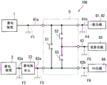
Fig. 1 is a diagram schematically showing an example of the configuration of an in-vehicle power supply system 100. The in-vehicle power supply system 100 is mounted on a vehicle. The in-vehicle power supply system 100 includes at least an in-vehicle power supply device 10 and loads 81 to 84. As illustrated in fig. 1, the in-vehicle power supply system 100 may further include a battery unit 22, a starter 3, a generator 4, a fuse box 7, a fuse bank 11, and a fuse 12. For example, the fuse set 11 is implemented by a Battery Fuse Terminal (BFT).
The in-vehicle power supply device 10 includes power storage devices 1 and 2 and a switching device 5. The switching device 5 is a switching device for a vehicle-mounted power supply, and power storage devices 1 and 2 are provided on the input side thereof, and loads 81 to 84 are provided on the output side thereof. The switching device 5 is a device for switching the electrical connection between the power storage devices 1 and 2 and the loads 81 to 84, and includes switches 51 to 53. The ON/OFF of the switches 51-53 is controlled by a control circuit 9.
The switches 51 to 53 are each constituted by a relay, for example, and the on/off of the relay corresponds to the on/off of the switches 51 to 53. In the case where the switches 51 to 53 are constituted by relays as described above, the switching device 5 can be handled as a relay module.
First, the connection relationship between the switches 51 to 53, the power storage devices 1 and 2, and the load 83 will be described. Switch 52 is connected between power storage device 1 and load 83, and switch 53 is connected between power storage device 2 and load 83. Switches 52 and 53 are connected in series between power storage devices 1 and 2. The switch 51 is connected in parallel with the set of switches 52, 53.
In the example of fig. 1, the switching device 5 includes connection points P1 to P5. The connection points P1-P5 and the switches 51-53 can be provided on a predetermined substrate, for example. Connection point P1 is connected to power storage device 1 via power supply line 61a and the first fuse in fuse group 11. For example, the power supply line 61a is a wire and is included in a wire harness. The same applies to power supply lines 62a, 63a, 61b, 62b, 63 described later. One end 52a of the switch 52 and one end 51a of the switch 51 are connected to the connection point P1. For example, one end 52a of the switch 52 and one end 51a of the switch 51 are connected to the connection point P1 via wiring patterns formed on a predetermined substrate.
Connection point P2 is connected to power storage device 2 via power supply line 62a, battery cell 22, power supply line 63a, and fuse 12 in this order. The battery unit 22 is, for example, a relay or a bidirectional DC/DC converter, and is capable of controlling electrical connection/disconnection between the power supply lines 62a, 63 a. When the battery cell 22 is a bidirectional DC/DC converter, the battery cell 22 performs voltage conversion between the voltage of the power supply line 62a and the voltage of the power supply line 63 a. For example, when power storage device 2 is charged, the voltage on power supply line 62a side is converted into a desired voltage and output to power supply line 63a, and when power storage device 2 is discharged, the voltage on power supply line 63a side is converted into a desired voltage and output to power supply line 62 a. The operation of the battery unit 22 is controlled by the control circuit 9, for example. The connection point P2 is connected to the one end 53a of the switch 53 and the other end 51b of the switch 51 via wiring patterns, for example.
The connection point P4 is connected to the load 83 via the power supply line 63 and the fuse 73. A plurality of loads may be connected to the connection point P4. In this case, a plurality of fuses may be provided corresponding to the plurality of loads. The connection point P4 is connected to the other end 52b of the switch 52 and the other end 53b of the switch 53 via wiring patterns, for example.
In such a configuration, the switch 52 is connected between the power storage device 1 and the load 83, the switch 53 is connected between the power storage device 2 and the load 83, and the switch 51 is connected in parallel to the set of switches 52 and 53.
The connection point P3 is connected to the load 81 via the power supply line 61b and the fuse 71, and is connected to the load 82 via the power supply line 61b and the fuse 72. The number of loads connected to the connection point P3 is not limited to 2, and may be 1 or more. The connection point P3 is connected to the one end 52a of the switch 52 and the one end 51a of the switch 51 via the wiring pattern, for example.
The connection point P5 is connected to the load 84 via the power supply line 62b and the fuse 74. A plurality of loads may be connected to the connection point P5. In this case, a plurality of fuses may be provided corresponding to a plurality of loads. The connection point P5 is connected to the one end 53a of the switch 53 and the other end 51b of the switch 51 via wiring patterns, for example. The fuses 71 to 74 can be housed in the fuse box 7. The connection points P1 to P5 may be connectors connected to the power lines 61a, 62a, 61b, 63, and 62b, respectively.
The power storage device 1 is a lead storage battery, for example. In the example of fig. 1, starter 3 is connected to power storage device 1 via a second fuse in fuse group 11. The starter motor 3 has a motor for starting the engine, and is denoted by "ST" in fig. 1.
The generator 4 is, for example, an alternator, and generates and outputs a dc voltage in accordance with rotation of an engine of the vehicle. In the illustration of fig. 1, the generator 4 is labeled "ALT". The Generator 4 may be an SSG (Side mounted Starter Generator). The generator 4 is connected to the power storage device 1 via a third fuse in the fuse set 11. The generator 4 can charge the power storage devices 1 and 2. The power storage device 2 is, for example, a lithium ion battery, a nickel metal hydride battery, or a capacitor.
In the illustration of fig. 1, loads 81, 82 are labeled as "normal loads", load 83 is labeled as "important loads", and load 84 is labeled as "VS loads". This point will be explained. The load 83 receives electric power from the power storage devices 1 and 2 via the switches 52 and 53, respectively. Therefore, when an abnormality occurs on the power storage device 1 side, even if the switch 52 is turned off and the power storage device 1 and the load 83 are disconnected, the load 83 can receive electric power from the power storage device 2 via the switch 53. The same applies to the case where an abnormality occurs in the power storage device 2. That is, redundant power is supplied to the load 83 connected to the connection point P4. Therefore, an important load that preferentially maintains the supply of electric power can be adopted as the load 83. For example, as the important load, a load related to travel control of the vehicle, a load related to automatic driving (for example, a control circuit (for example, a microcomputer) or the like), and a load related to safety of a driver may be used.
The loads 81 and 82 are connected to the power storage device 1 without using the switches 51 to 53, for example. Accordingly, for example, when a ground fault occurs in power supply line 61a as an abnormality on the side of power storage device 1, it is not possible to appropriately supply electric power to loads 81 and 82. Accordingly, it is preferable to use a general load that allows the power supply to be cut off for the loads 81 and 82. For example, as a general load, an interior lamp that illuminates the interior of the vehicle may be used.
In the example of fig. 1, the load 84 is connected to the power storage device 2 through the battery unit 22 without passing through the switches 51 to 53. When the battery cell 22 is a DC/DC converter, the battery cell 22 can convert the voltage from the power storage device 2 into a desired voltage and output the voltage to the load 84. Thus, when the relay is used, the battery unit 22 can supply a more stable voltage to the load 84. Therefore, it is preferable to use a VS (Voltage-stabilized) load as the load 84, which does not require a power supply to be maintained as compared with an important load and requires a stable Voltage as compared with a general load. The stable voltage referred to herein is a voltage that is not easily lower than the lower limit of the operability of the load, for example, is not easily subjected to transient shutdown. For example, as the VS load, a control circuit (for example, a microcomputer) or the like that controls a load mounted on the vehicle may be used.
In the in-vehicle power supply system 100, the switch 51 has a resistance value smaller than the resistance values of the switches 52 and 53. For example, the resistance values of the switches 52 and 53 are several (e.g., 2 to 3) [ m Ω ], and the resistance value of the switch 51 is several hundred (e.g., about 100) [ μ Ω ]. Such a switch 51 has a size larger than the size of the switches 52, 53. For example, the switch 51 has a size of several hundred (e.g., 200 left and right) [ mm ] × several hundred (e.g., 300 left and right) [ mm ] in a top view, and the switches 52 and 53 have a size of several tens (e.g., 20 left and right) [ mm ] × several tens (e.g., 20 left and right) [ mm ] in a top view. The switch 51 is more expensive than the switches 52 and 53. For example, the price of the switch 51 is about one hundred times the price of the switches 52 and 53.
The control circuit 9 controls the switches 51 to 53 and the battery unit 22. The Control circuit 9 may be, for example, an ECU (Electrical Control Unit) or a BCM (Body Control Module) that performs collective Control of the vehicles.
Here, the control circuit 9 includes a microcomputer and a storage device. The microcomputer executes each processing step (in other words, flow) described in the program. The storage device may be one or more of various storage devices such as a ROM (Read Only Memory), a RAM (Random Access Memory), a rewritable nonvolatile Memory (eprom (erasable Programmable ROM)), and a hard disk device. The storage device stores various information, data, and the like, stores a program to be executed by the microcomputer, and provides a work area for executing the program. The microcomputer can be understood to function as various means corresponding to each processing step described in the program, or can be understood to realize various functions corresponding to each processing step. Further, the control circuit 9 is not limited to this, and a part or all of various procedures executed by the control circuit 9 or various means implemented or various functions may be implemented by a hardware circuit. The same applies to other control circuits described later.
< control >
The control circuit 9 controls the switches 51 to 53 and the battery unit 22 according to, for example, the traveling state of the vehicle. The following table shows an example of the switching pattern employed during the traveling of the vehicle.
[ Table 1]

For example, the control circuit 9 adopts any one of the control modes A, C when the power storage device 2 is charged. That is, the control circuit 9 turns on the switch 51 when charging the power storage device 2. Fig. 2 is a flowchart showing an example of the operation of the control circuit 9. First, in step ST1, the control circuit 9 determines whether or not to charge the power storage device 2. For example, when deceleration of the vehicle is detected, it may be determined that the power storage device 2 is charged. For example, a detector for detecting an accelerator opening degree may be provided to determine whether or not such a vehicle is decelerated based on the accelerator opening degree. When determining that the power storage device 2 is not to be charged, the control circuit 9 executes step ST1 again. When determining that the power storage device 2 is to be charged, the control circuit 9 turns on the switch 51 in step ST 2.
This allows power storage device 2 to be charged via switch 51 having a resistance value smaller than the resistance values of switches 52 and 53. This is preferable in comparison with the case where power storage device 2 is charged only via switches 52 and 53, that is, via a large resistance. That is, for example, when the power storage device 2 is charged with the constant current (I), the loss (R · I) generated in the switch is small because the resistance (R) is small2) Is small. Further, for example, when power storage device 2 is charged at a constant voltage, the charging current can be increased because the resistance is small. Further, the charging time can be shortened.
Note that, unlike the present embodiment, the above-described effects can be obtained even if the resistance values of the switches 52 and 53 are reduced without providing the switch 51. For example, low-resistance switches having a resistance value of about half the resistance value of the switch 51 may be used as the switches 52 and 53. However, as described above, the size of such a low-resistance switch is large, and if the low-resistance switch is employed for the 2 switches 52, 53, the size of the switching device 5 increases. Further, as described above, such a low resistance switch is expensive, and if the low resistance switch is used for the 2 switches 52 and 53, the cost of the switching device 5 increases.
In contrast, in the present embodiment, the switch 51 having a small resistance value is provided in parallel with the switches 52 and 53. This can reduce the size and cost of the switching device 5, as compared with the case of using low-resistance switches as the 2 switches 52 and 53.
< ground fault >
Ground faults may occur in the power lines 61a to 63a, 61b, 62b, 63. Fig. 3 is a diagram schematically showing examples of ground faults F1 to F6 generated in the power supply lines 61a, 63a, 62a, 61b, 63, 62b, respectively. In the example of fig. 3, the ground faults F1 to F6 are represented by ground fault symbols. In the example of fig. 3, the starter 3, the generator 4, the fuse box 7, the control circuit 9, the fuse set 11, and the fuse 12 are not shown to avoid complexity of the drawing. In the drawings referred to below, they are also omitted as appropriate.
For example, when only the ground fault F1 occurs in the power supply line 61a, a large current (hereinafter, also referred to as a ground fault current) flows from the power storage device 1 to the ground fault F1. In this case, power storage device 1 cannot appropriately supply electric power to loads 81 to 84. At this time, if the switch 52 and the switch 53 or the switch 51 are turned on, a ground fault current flows from the power storage device 2 to the ground fault F1 through the turned-on switch among the switches 51 to 53. In this case, power storage device 2 cannot properly supply power to loads 81 to 84.
When other ground faults F2 to F6 occur, electric power cannot be appropriately supplied from the power storage device 1 or the power storage device 2. Therefore, when the ground faults F1 to F6 occur, the power supply to the loads 81 to 84 is maintained as much as possible by controlling the switches 51 to 53 according to the ground fault locations. The generation of each ground fault can be detected based on voltage or current. For example, a detector for detecting a voltage applied to the power supply lines 61a and 61b or a current flowing through the power supply lines 61a and 61b is provided, and generation of the ground faults F1 and F4 can be detected based on the detection result. The same applies to other ground faults.
The following table shows the switching patterns employed when the ground faults F1-F6 occur.
[ Table 2]

< ground faults F1, F4>
For example, when at least one of the ground faults F1 and F4 occurs on the power storage device 1 side, the control circuit 9 turns off the switches 51 and 52 and turns on the switch 53 and the battery unit 22. Fig. 4 is a diagram schematically showing an example of the in-vehicle power supply system 100 in the case where the ground faults F1 and F4 occur. As shown in fig. 4, the switches 51 and 52 are off, and the switch 53 is on. Further, since the battery unit 22 is also turned on, the power storage device 2 can supply electric power to the loads 83 and 84. In the example of fig. 4, the path of this power supply is indicated by block-shaped arrows.
When at least one of the ground faults F1 and F4 occurs, the power cannot be appropriately supplied to the loads 81 and 82. That is, when at least one of the ground faults F1 and F4 occurs, the power supply to the loads 81 and 82 is abandoned, and the power supply to the loads 83 and 84 by the power storage device 2 is performed.
Fig. 5 is a diagram schematically showing an example of a time chart when at least one of the ground faults F1 and F4 occurs in each of the control patterns a to C. In the upper time chart of fig. 5, the control pattern a is initially adopted. That is, initially, the switches 51 to 53 and the battery cell 22 are turned on. In response to detection of at least one of the ground faults F1 and F4, the control circuit 9 turns off the switches 51 and 52 at a time t1 after the detection of the ground fault. Thereby, the switches 51 and 52 are turned off, and the switch 53 and the battery unit 22 are turned on.
In the middle time chart of fig. 5, control pattern B is initially adopted. That is, at first, the switches 51 and 52 are turned off, and the switch 53 and the battery unit 22 are turned on. This switching pattern is the same as the switching pattern employed when at least one of the ground faults F1 and F4 occurs. Thus, the control circuit 9 does not change the switching pattern even when at least one of the ground faults F1 and F4 is detected.
In the lower timing chart of fig. 5, the control pattern C is initially adopted. That is, initially, the switch 52 is turned off, and the switches 51 and 53 and the battery unit 22 are turned on. In response to at least one of the ground faults F1, F4 being detected, the control circuit 9 turns off the switch 51 at a time point t 1.
< control mode A >
In the control mode a of fig. 5, the control circuit 9 switches 2 switches 51, 52. However, the control circuit 9 may not be able to switch the switches 51 and 52 simultaneously. In this case, the control circuit 9 preferably turns off the switch 51 before the switch 52 is turned off. Fig. 6 is a schematic view showing an example of a time chart thereof. The control circuit 9 turns off the switch 51 at a time point t1, and turns off the switch 52 at a later time point t 2. That is, the control circuit 9 turns off the switch 51 having a small resistance value first, and turns off the switch 52 having a large resistance value later.
Thus, the total amount of the ground fault current flowing from the power storage device 2 to the ground fault F1 or the ground fault F4 can be reduced as compared with the case where the order of turning off the switches 51 and 52 is reversed. That is, since a large amount of ground fault current flows from the power storage device 2 through the switch 51 having a smaller resistance value than the switch 52, the ground fault current can be reduced by first turning off the switch 51.
< ground fault F2>
Upon detecting that the ground fault F2 occurs in the power supply line 63a, the control circuit 9 turns off the battery unit 22 (see also table 2). This can cut off the power supply line 63a from the switching device 5. At this time, the power storage device 2 and the switching device 5 are disconnected from each other, and thus power cannot be supplied to the loads 81 to 84. Therefore, in order to supply electric power from the power storage device 1 to the loads 81 to 84, the control circuit 9 adopts any one of the 4 switching patterns indicated in table 2 in correspondence with the ground fault F2.
However, the smaller the number of times of switching of the switch, the smaller the load on the control circuit 9. Thus, the control circuit 9 may adopt the switching mode so as to reduce the number of times of switching of the switches. For example, when the ground fault F2 is detected in the control mode a, the control circuit 9 may turn off the battery cell 22 and maintain the switching states of the switches 51 to 53. Fig. 7 is a schematic diagram showing an example of the time chart. In response to the detection of the ground fault F2, the control circuit 9 turns off the battery cell 22 at time t1 and maintains the switches 51 to 53 on. Thus, when the ground fault F2 occurs, electric power can be supplied from the power storage device 1 to the loads 81 to 84 via the switches 51 to 53. Since the on/off states of the switches 51 to 53 are not switched before and after the ground fault F2 is detected, the load on the control circuit 9 is small.
Next, consider the ground fault F2 in control mode B. In the control mode B, if the ground fault F2 occurs, the control circuit 9 needs to switch the switching states of the switches 51 to 53 as appropriate, in addition to the battery cells 22. The reason is that, when the battery unit 22 is turned off in the control mode B, the power cannot be supplied from the power storage device 2 to the loads 83 and 84.
However, in order to reduce the number of times of switching of the switch, it is desirable to effectively use the on of the switch 53 in the control mode B. That is, it is desirable not to turn off the switch 53. Fig. 8 is a schematic view showing an example of a time chart. In the illustration of fig. 8, 3 time diagrams are shown. In the upper time chart, the control circuit 9 turns on the switch 51 and turns off the battery cell 22 at a time point t1 in response to the detection of the ground fault F2. At this time, the power storage device 1 directly supplies power to the loads 81 and 82, supplies power to the load 83 via the switches 51 and 53, and supplies power to the load 84 via the switch 51.
In the middle time chart of fig. 8, in response to the detection of the ground fault F2, the control circuit 9 turns on the switch 52 at a time point t1 to turn off the battery cell 22. At this time, power storage device 1 directly supplies power to loads 81 and 82, supplies power to load 83 via switch 52, and supplies power to load 84 via switches 52 and 53.
In the lower timing chart of fig. 8, the control circuit 9 turns on the switches 51 and 52 at time t1 to turn off the battery cell 22. At this time, the power storage device 1 directly supplies power to the loads 81 and 82, supplies power to the load 83 via the switch 52, and supplies power to the load 84 via the switches 51 to 53. In the point of the number of times of switching of the switch, the upper and middle stages of control in fig. 8 are preferable.
When the control circuit 9 cannot simultaneously switch the switching states of the plurality of switches and the operation of the battery cell 22, the control circuit 9 preferably turns off the battery cell 22 most preferentially. This can cut off the ground fault current flowing from the power storage device 1 to the ground fault F2. Fig. 9 is a schematic view showing an example of a time chart thereof. In the upper time chart of fig. 9, the control circuit 9 turns off the battery cell 22 at time t1, and turns on the switch 51 at a later time t 2. In the middle time chart of fig. 9, the control circuit 9 turns off the battery cell 22 at time t1, and turns on the switch 52 at a subsequent time t 2.
In the lower timing chart of fig. 9, the control circuit 9 turns off the battery cell 22 at time t1, turns on the switch 51 at a later time t2, and turns on the switch 52 at a later time t 3. In this example, switch 51 is turned on before switch 52. The reason for this will be described. The switch 51 has a smaller resistance value than the switch 52, and the current capacity of the switch 51 is larger than that of the switch 52. That is, even when the current (power supply current) flowing to the load 84 is large, by turning on the switch 51 earlier than the switch 52, the power supply current can be appropriately flowed from the power storage device 1 to the load 84 via the switch 51.
Further, by turning on not only the switch 51 but also the switch 52, the power storage device 1 can supply electric power to the load 83 via the switch 52. Thus, power can be supplied to the load 83 via one switch 52 with a smaller resistance than via 2 switches 51 and 53.
Fig. 10 is a diagram schematically showing an example of a time chart when the ground fault F2 occurs in the control mode C. In the example of fig. 10, the control circuit 9 turns off the battery cell 22 at a time point t1 in response to the detection of the ground fault F2, and maintains the switching states of the switches 51 to 53. Thus, when the ground fault F2 occurs, electric power can be supplied from the power storage device 1 to the loads 81 to 84. In this example, the switches 51 to 53 are not switched on and off before and after the ground fault F2 is detected, and therefore the load on the control circuit 9 is small.
< ground faults F3, F6>
When at least one of the ground faults F3 and F6 on the power storage device 2 side occurs, the control circuit 9 turns on the switch 52 and turns off the switches 51 and 53 (see also table 2). And the battery cell 22 is disconnected. Fig. 11 is a diagram schematically showing an example of the in-vehicle power supply system in which the ground faults F3 and F6 occur. As shown in fig. 11, since the switch 52 is turned on and the switches 51 and 53 are turned off, the power storage device 1 can supply electric power to the loads 81 to 83. In the example of fig. 11, the path of this power supply is indicated by block-shaped arrow marks.
When at least one of the ground faults F3 and F6 occurs, power cannot be appropriately supplied to the load 84. That is, when at least one of the ground faults F3 and F6 occurs, the power supply to the loads 81 to 83 by the power storage device 1 is performed without the power supply to the load 84.
Fig. 12 is a diagram schematically showing an example of a time chart when at least one of the ground faults F3 and F6 occurs in each of the control patterns a to C. In the upper time chart of fig. 12, the control pattern a is initially adopted. In response to detection of at least one of the ground faults F3 and F6, the control circuit 9 turns off the switches 51 and 53 at time t1 to turn off the battery cell 22.
In the middle time chart of fig. 12, the control pattern B is initially adopted. In response to detection of at least one of the ground faults F3 and F6, the control circuit 9 turns on the switch 52 at time t1, turns off the switch 53, and turns off the battery cell 22.
In the lower timing chart of fig. 12, the control pattern C is initially adopted. In response to detection of at least one of the ground faults F3 and F6, the control circuit 9 turns on the switch 52, turns off the switches 51 and 53, and turns off the battery cell 22 at time t 1.
When the switching states of the plurality of switches and the operation of the battery cell 22 cannot be switched simultaneously, the control circuit 9 can perform control as described below. Fig. 13 is a schematic view showing an example of a time chart thereof.
In the upper timing chart of fig. 13, when the control mode a is initially adopted, the control circuit 9 turns off the switch 51 first at a time point t1 in response to at least one of the ground faults F3, F6. The control circuit 9 turns off the switch 53 at a later point in time t2 and turns off the battery cell 22 at a later point in time t 3.
As described above, the switch 51 having a small resistance value is turned off earlier than the switch 53 having a large resistance value. Accordingly, the ground fault current flowing from the power storage device 1 to the ground fault F3 or the ground fault F6 via the switch 51 having a small resistance value can be cut off preferentially as compared with the case of the opposite. The disconnection of the battery unit 22 does not contribute to the supply of electric power from the power storage device 1 to the loads 81 to 83. This reduces the priority of turning off the battery cells 22. Therefore, as described above, the control circuit 9 turns off the battery cell 22 after the switches 51, 53 are switched. In the other timing charts of fig. 13, the battery unit 22 is turned off after the control of the switches 51 to 53, as appropriate, for the same reason.
In the middle time chart of fig. 13, when the control mode B is initially adopted, the control circuit 9 turns off the switch 53 first at a time point t1 in response to at least one of the ground faults F3 and F6. The control circuit 9 turns on the switch 52 at a later time point t2, and turns off the battery cell 22 at a later time point t 3.
As described above, the switch 53 is turned off before the switch 52 is turned on. This can bring about the following effects as compared with the case of the opposite case. That is, if the switch 52 is turned on first before the switch 53 is turned off, the switches 52, 53 are turned on simultaneously. At this time, a ground fault current flows from the power storage device 1 to the ground fault F3 or the ground fault F6 via the switches 52 and 53. Such a ground fault current does not contribute to the operation of the loads 81 to 84. Therefore, by turning off the switch 53 before turning on the switch 52, it is possible to avoid the switches 52 and 53 from being simultaneously turned on, and thus it is possible to avoid such a ground fault current.
In the lower timing chart of fig. 13, when the control mode C is initially adopted, the control circuit 9 turns off the switch 51 first at a time t1 in response to at least one of the ground faults F3 and F6. The control circuit 9 turns off the switch 53 at a later time point t2, turns on the switch 52 at a later time point t3, and turns off the battery cell 22 at a later time point t 4.
This can cut off the path from the power storage device 1 to the ground fault F3 or the ground fault F6 via the small resistor (switch 51) first. Next, in order to avoid simultaneous conduction of the switches 52 and 53, the switch 52 is turned on after the switch 53 is turned off. This reduces the ground fault current and supplies power to the loads 81-83.
< ground fault F5>
When the ground fault F5 on the load 83 side occurs, the switches 52 and 53 are turned off because power cannot be supplied to the load 83 (see also table 2). This can cut off power storage devices 1 and 2 from power supply line 63. Referring to the switching pattern of the ground fault F5 in table 2, in this state, at least one of the switch 51 and the battery unit 22 is turned on, and thereby at least one of the power storage devices 1 and 2 supplies electric power to the loads 81, 82, and 84.
For example, when the switch 51 and the battery unit 22 are turned on, electric power is supplied from both the power storage devices 1 and 2 to the loads 81, 82, and 84. When the switch 51 is off and the battery unit 22 is on, only the power storage device 1 supplies power to the loads 81 and 82, and only the power storage device 2 supplies power to the load 84. When the switch 51 is turned on and the battery unit 22 is turned off, the power storage device 1 supplies electric power to the loads 81, 82, and 84.
When the ground fault F5 occurs, any of the above-described switching patterns may be adopted, but the following description will be given of a case where the switch 51 and the battery cell 22 are turned on.
Fig. 14 is a schematic view showing an example of a time chart thereof. In the illustration of fig. 14, 3 time diagrams are shown. In the upper time chart of fig. 14, the control pattern a is initially adopted. The control circuit 9 turns off the switches 52, 53 at a time point t1 in response to the ground fault F5 being detected.
In the middle time chart of fig. 14, the control pattern B is initially adopted. In response to the detection of the ground fault F5, the control circuit 9 turns off the switch 53 and turns on the switch 51 at a time point t 1.
In the lower timing chart of fig. 14, the control pattern C is initially adopted. The control circuit 9 turns off the switch 53 at a time point t1 in response to the ground fault F5 being detected.
In the example of fig. 14, in the control mode A, B, the control circuit switches the plurality of switches. When the plurality of switches cannot be switched at the same time, the control circuit 9 can perform control as described below. Fig. 15 schematically shows an example of the time chart. In the upper time chart of fig. 15, the control pattern a is initially adopted. The control circuit 9 turns off the switch 53 at a time point t2 after turning off the switch 52 at a time point t 1. This ensures the amount of power stored in the power storage device 1, as compared with the case where the amount is reversed. When power storage device 1 is a lead-acid battery, a dark current flows from power storage device 1 to loads 81 and 82 when the vehicle is stopped. Thus, it is preferable to preferentially secure the amount of power stored in the power storage device 1 in terms of securing the dark current.
In the lower timing chart of fig. 15, the control pattern B is initially adopted. The control circuit 9 turns on the switch 51 after turning off the switch 53 at a time point t 1. This makes it possible to cut off the ground fault current flowing from the power storage devices 1 and 2 to the ground fault F5 earlier than in the opposite case.
< modification example >
Fig. 16 is a diagram showing an example of a schematic configuration of the in-vehicle power supply system 100. In the example of fig. 16, the battery unit 22 is a bidirectional DC/DC converter and incorporates a control circuit 221. The control circuit 221 receives a charge/discharge command from the control circuit 9, and operates the DC/DC converter based on the command. For example, when control circuit 221 receives a charging command, it causes DC/DC converter to convert the voltage of power supply line 62a into a desired voltage and output it to power storage device 2 via power supply line 63 a. For example, when the control circuit 221 receives a discharge instruction, it causes the DC/DC converter to convert the voltage of the power supply line 63a into a desired voltage and output the voltage to the power supply line 62 a.
Alternatively, the control circuit 221 may receive vehicle information from the control circuit 9 and determine the charging and discharging of the power storage device 2 based on the vehicle information. For example, the control circuit 221 may receive information indicating whether the generator 4 generates power as the vehicle information. The control circuit 221 may determine that the power storage device 2 is charged when the generator 4 generates power, and may determine that the power storage device 2 is discharged when the generator 4 stops generating power.
When the current flowing through the DC/DC converter exceeds the upper limit value, the control circuit 221 may control the DC/DC converter so that the current is smaller than the upper limit value, or may stop the DC/DC converter.
When the current flowing through the DC/DC converter is limited by the control circuit 221 in this way, the control circuit 9 can prevent the battery cell 22 from operating in accordance with the ground fault F2 generated in the power supply line 63 a. The reason is that the current flowing from the power storage device 1 to the ground fault F2 passes through the DC/DC converter of the battery unit 22, and therefore does not increase as much as the normal ground fault current.
When the current flowing through the DC/DC converter exceeds the upper limit value, the control circuit 221 stops (turns off) the DC/DC converter, and as a result, the above-described operation is performed. In this case, the control circuit 221 stops the DC/DC converter without an instruction from the control circuit 9. This allows the battery unit 22 to be stopped simultaneously with the control of the switches 51 to 53. For example, as shown in the upper timing chart of fig. 8, when the ground fault F2 occurs, the turning on of the switch 51 and the stopping of the battery cell 22 can be performed simultaneously. The same applies to other ground faults.
Fig. 17 is a diagram showing another example of the schematic configuration of the in-vehicle power supply system 100. In the example of fig. 17, the battery unit 22 is housed in the switch device 5. For example, the switch device 5 may have a package body, and the switches 51 to 53 and the battery unit 22 may be housed in the package body. This facilitates handling of the switch device 5 and mounting on the vehicle. Moreover, the control circuit 9 is easily housed in the battery unit 22. The control circuit 9 receives the vehicle information from the control circuit 91 of the upper layer. The control circuit 9 selects a control mode based on the vehicle information.
Fig. 18 is a diagram showing another example of the schematic configuration of the in-vehicle power supply system 100. In the example of fig. 18, the control circuit 9 is housed in the switching device 5, as compared with fig. 1. For example, the switch device 5 has a package, and the switches 51 to 53 and the control circuit 9 are housed in the package. The control circuit 9 can communicate with a control circuit on an upper layer (for example, an external ECU), for example. The control circuit 9 can control the switches 51 to 53 and the battery unit 22 based on the vehicle information transmitted from the upper control circuit.
In the example of fig. 18, the control circuit 9 receives electric power from the power storage devices 1 and 2 as operating electric power. For example, the power storage device 1 is connected to the control circuit 9 via a diode D1. The forward direction of the diode D1 is the direction from the power storage device 1 toward the control circuit 9. The power storage device 2 is connected to the control circuit 9 via a diode D2. The forward direction of the diode D2 is the direction from the power storage device 2 toward the control circuit 9. Since the vehicle body is normally set to a low potential (ground fault), the cathodes of the diodes D1 and D2 are connected to each other here.
Fig. 19 is a diagram showing another example of the schematic configuration of the in-vehicle power supply system 100. In the example of fig. 19, a control circuit 92 is further provided as compared with fig. 18. The control circuit 92 may be housed in the switching device 5. Then, the control circuit 92 receives electric power from the power storage devices 1 and 2. In the example of fig. 19, the power storage device 1 is connected to the control circuit 92 via a diode D3. The forward direction of the diode D3 is the direction from the power storage device 1 toward the control circuit 92. The power storage device 2 is connected to the control circuit 92 via a diode D4. The forward direction of the diode D4 is the direction from the power storage device 2 toward the control circuit 92. Here, the case where the cathodes of the diodes D3 and D4 are connected to each other is exemplified.
The control circuit 92 can also control the switches 51 to 53 and the battery unit 22. For example, the logical sum of the outputs of the control circuits 9 and 92 can be used as the control signals for the switches 51 to 53 and the battery unit 22. Thus, even if one of the control circuits 9 and 92 fails, the other can control the switches 51 to 53 and the battery unit 22. That is, redundancy of the control circuit can be achieved.
Alternatively, for example, the logical product of the outputs of the control circuits 9 and 92 may be used as the control signals for the switches 51 to 53 and the battery cell 22. Thus, when one of the control circuits 9 and 92 is out of control, the other can turn off the switches 51 to 53 and the battery unit 22. In this case, redundancy of the control circuit can be achieved. For example, when there is no response from the control circuit 92 to an inquiry from the control circuit 9, the control circuit 9 may end the operation of the control circuit 92, and the control circuit 9 may control the switches 51 to 53 and the battery unit 22. The reverse is also true.
The configurations described in the embodiments and the modifications may be appropriately combined as long as they are not contradictory to each other.
The present invention has been described in detail as above, but the above description is illustrative in all aspects and the present invention is not limited thereto. It is understood that numerous modifications, not illustrated, may be made without departing from the scope of the invention. For example, a mode other than the control mode shown in table 1 may be adopted. In addition, not only the ground faults of the power supply lines 61a, 62a, 63a, 61b, 62b, 63 but also the ground faults of the wiring pattern in the switching device 5 and the ground faults generated in the power storage devices 1, 2 may be considered.
Description of the reference numerals
1. 2 power storage devices (first power storage device, second power storage device);
5 a switching device;
9 a control circuit;
10 a vehicle-mounted power supply device;
22 a battery cell;
51-53 switches (first-third switches);
81-84 load.
Claims (6)
1. A switching device for an in-vehicle power supply includes:
a first switch connected between the first load and the first power storage device;
a second switch connected between the first load and a second power storage device; and
a third switch connected between the first power storage device and the second power storage device, connected in parallel with the set of the first switch and the second switch, and having a resistance value smaller than both a resistance value of the first switch and a resistance value of the second switch,
the switching device for the vehicle-mounted power supply further includes a control circuit for on/off controlling the first switch, the second switch, and the third switch,
when it is detected that a ground fault has occurred on the first power storage device side relative to the first switch and the third switch, the control circuit turns off the third switch and turns on the second switch before turning off the first switch, so that the first load can receive electric power from the second power storage device via the second switch.
2. A switching device for an in-vehicle power supply includes:
a first switch connected between the first load and the first power storage device;
a second switch connected between the first load and a second power storage device; and
a third switch connected between the first power storage device and the second power storage device, connected in parallel with the set of the first switch and the second switch, and having a resistance value smaller than both a resistance value of the first switch and a resistance value of the second switch,
the switching device for the vehicle-mounted power supply further includes a control circuit for on/off controlling the first switch, the second switch, and the third switch,
when it is detected that a ground fault has occurred on the second power storage device side with respect to the second switch and the third switch, the control circuit turns off the third switch and turns on the first switch before turning off the second switch, so that the first load can receive electric power from the first power storage device via the first switch.
3. The switching device for the in-vehicle power supply according to claim 1 or 2,
the first electrical storage device is a lead storage battery,
the control circuit turns off the first switch before turning off the second switch when detecting that a ground fault has occurred on the first load side of the first switch.
4. The switching device for the in-vehicle power supply according to claim 1 or 2,
one end of the second switch on the second power storage device side is connected to the second power storage device via a battery cell that is a switch or a bidirectional DC/DC converter,
the control circuit turns off the battery cell when detecting that a ground fault has occurred on the second power storage device side of the battery cell in a state where the second switch and the third switch are on or in a state where the first switch is on.
5. The switching device for the vehicle-mounted power supply according to claim 3,
one end of the second switch on the second power storage device side is connected to the second power storage device via a battery cell that is a switch or a bidirectional DC/DC converter,
the control circuit turns off the battery cell when detecting that a ground fault has occurred on the second power storage device side of the battery cell in a state where the second switch and the third switch are on or in a state where the first switch is on.
6. An in-vehicle power supply device is provided with:
the switching device for a vehicle-mounted power supply according to any one of claims 1 to 5; and
the first electrical storage device and the second electrical storage device.
Applications Claiming Priority (3)
| Application Number | Priority Date | Filing Date | Title |
|---|---|---|---|
| JP2016-027719 | 2016-02-17 | ||
| JP2016027719A JP6597371B2 (en) | 2016-02-17 | 2016-02-17 | In-vehicle power supply switch device and in-vehicle power supply device |
| PCT/JP2017/003305 WO2017141686A1 (en) | 2016-02-17 | 2017-01-31 | Switch device for in-vehicle power supply, and in-vehicle power supply device |
Publications (2)
| Publication Number | Publication Date |
|---|---|
| CN108602478A CN108602478A (en) | 2018-09-28 |
| CN108602478B true CN108602478B (en) | 2021-10-08 |
Family
ID=59624954
Family Applications (1)
| Application Number | Title | Priority Date | Filing Date |
|---|---|---|---|
| CN201780008701.1A Active CN108602478B (en) | 2016-02-17 | 2017-01-31 | Switching device for vehicle-mounted power supply and vehicle-mounted power supply device |
Country Status (4)
| Country | Link |
|---|---|
| US (1) | US20180354436A1 (en) |
| JP (1) | JP6597371B2 (en) |
| CN (1) | CN108602478B (en) |
| WO (1) | WO2017141686A1 (en) |
Families Citing this family (24)
| Publication number | Priority date | Publication date | Assignee | Title |
|---|---|---|---|---|
| JP6728991B2 (en) * | 2016-05-31 | 2020-07-22 | 株式会社オートネットワーク技術研究所 | Relay device and power supply device |
| DE102017104958B4 (en) * | 2017-03-09 | 2024-03-14 | Dr. Ing. H.C. F. Porsche Aktiengesellschaft | Battery storage system |
| DE102017006678A1 (en) * | 2017-07-14 | 2019-01-17 | Drägerwerk AG & Co. KGaA | Cascadable multi-loader and method of operation thereof |
| US10829066B2 (en) * | 2017-09-22 | 2020-11-10 | Zoox, Inc. | Fail operational vehicle power supply |
| JP7003706B2 (en) * | 2018-02-06 | 2022-01-21 | トヨタ自動車株式会社 | Power system |
| JP6732831B2 (en) * | 2018-04-10 | 2020-07-29 | 矢崎総業株式会社 | Power supply |
| JP7070260B2 (en) * | 2018-09-10 | 2022-05-18 | 株式会社オートネットワーク技術研究所 | Wiring branch box |
| JP2020072620A (en) * | 2018-11-02 | 2020-05-07 | トヨタ自動車株式会社 | Power supply circuit protective device |
| JP7014144B2 (en) * | 2018-12-12 | 2022-02-01 | 株式会社オートネットワーク技術研究所 | Power distributor |
| CN109466478B (en) * | 2018-12-21 | 2020-10-09 | 鄂尔多斯市普渡科技有限公司 | Distributed power supply system for unmanned vehicle |
| JP7182089B2 (en) * | 2019-02-08 | 2022-12-02 | 矢崎総業株式会社 | power control unit |
| JP7181114B2 (en) * | 2019-02-08 | 2022-11-30 | 矢崎総業株式会社 | power control unit |
| JP7074717B2 (en) * | 2019-04-25 | 2022-05-24 | 矢崎総業株式会社 | Power supply system |
| DE102019112706A1 (en) * | 2019-05-15 | 2020-11-19 | Bayerische Motoren Werke Aktiengesellschaft | Method and device for supplying energy to an electrical consumer of a vehicle |
| US20210028632A1 (en) * | 2019-07-25 | 2021-01-28 | Samsung Sdi Co., Ltd. | Battery system |
| JP7106228B2 (en) * | 2019-08-27 | 2022-07-26 | 矢崎総業株式会社 | vehicle power system |
| DE102019007956A1 (en) * | 2019-10-24 | 2021-04-29 | Daimler Ag | Electronic power supply system |
| JP7013500B2 (en) * | 2020-01-30 | 2022-01-31 | 矢崎総業株式会社 | Vehicle power system |
| US20210380054A1 (en) * | 2020-06-04 | 2021-12-09 | Transportation Ip Holdings, Llc | Electric supply system |
| JP2022152408A (en) * | 2021-03-29 | 2022-10-12 | 株式会社デンソーテン | Power supply device and determination method |
| JP2023092656A (en) * | 2021-12-22 | 2023-07-04 | 株式会社デンソーテン | Power supply control device and control method |
| NL2030816B1 (en) * | 2022-02-03 | 2023-08-11 | Lightyear Ipco B V | Battery management system, electric vehicle, method and control unit |
| US11813995B2 (en) * | 2022-03-15 | 2023-11-14 | Ree Automotive Ltd. | Redundant power distribution system based on single power source |
| DE102022204201A1 (en) * | 2022-04-29 | 2023-11-02 | Vitesco Technologies GmbH | Security circuit arrangement for an energy system and energy system |
Family Cites Families (8)
| Publication number | Priority date | Publication date | Assignee | Title |
|---|---|---|---|---|
| JP3570823B2 (en) * | 1996-07-31 | 2004-09-29 | 富士通テン株式会社 | Multiplex transmission equipment |
| US6798175B2 (en) * | 2000-04-11 | 2004-09-28 | Pentax Corporation | Power supply circuit |
| JP4158546B2 (en) * | 2003-02-13 | 2008-10-01 | 株式会社日立製作所 | Automotive power supply |
| EP2477040A4 (en) * | 2010-10-08 | 2014-08-13 | Sanyo Electric Co | Ground fault detection circuit, and ground fault detection device |
| US8947048B2 (en) * | 2011-07-29 | 2015-02-03 | Infineon Technologies Ag | Power supply system with charge balancing |
| US20130082639A1 (en) * | 2011-10-04 | 2013-04-04 | GM Global Technology Operations LLC | Electrical system having a primary energy source and a redundant rechargeable energy source |
| JPWO2014061137A1 (en) * | 2012-10-18 | 2016-09-05 | 三菱電機株式会社 | Power management system and power management method |
| JP5817767B2 (en) * | 2013-03-21 | 2015-11-18 | トヨタ自動車株式会社 | Electric car |
-
2016
- 2016-02-17 JP JP2016027719A patent/JP6597371B2/en active Active
-
2017
- 2017-01-31 US US15/780,663 patent/US20180354436A1/en not_active Abandoned
- 2017-01-31 WO PCT/JP2017/003305 patent/WO2017141686A1/en active Application Filing
- 2017-01-31 CN CN201780008701.1A patent/CN108602478B/en active Active
Also Published As
| Publication number | Publication date |
|---|---|
| CN108602478A (en) | 2018-09-28 |
| JP2017144860A (en) | 2017-08-24 |
| US20180354436A1 (en) | 2018-12-13 |
| WO2017141686A1 (en) | 2017-08-24 |
| JP6597371B2 (en) | 2019-10-30 |
Similar Documents
| Publication | Publication Date | Title |
|---|---|---|
| CN108602478B (en) | Switching device for vehicle-mounted power supply and vehicle-mounted power supply device | |
| CN109075590B (en) | Switching device for vehicle-mounted power supply and vehicle-mounted power supply system | |
| CN108495771B (en) | Switching device for vehicle-mounted power supply and vehicle-mounted power supply | |
| US10933751B2 (en) | Power distribution system | |
| CN107949972B (en) | Switching device and control device for vehicle-mounted power supply | |
| US20210020998A1 (en) | Power pack and power pack circuitry | |
| US10279761B2 (en) | Vehicle power-supply device | |
| US10838474B2 (en) | Electric power supply system | |
| US20150097426A1 (en) | Electric vehicle power conversion system | |
| US20190256018A1 (en) | Vehicular electric power supply system | |
| CN107963040B (en) | Battery pack device, operating method for battery pack device, and vehicle | |
| US11843274B2 (en) | Charge control apparatus for controlling charging of an energy storage device via purality of charging paths connected in parallel anssociated energy storage appartus, and an associated charging method | |
| JP2009261230A (en) | Electric vehicle charging system | |
| JP4984069B2 (en) | Vehicle power supply | |
| US20220097634A1 (en) | Power supply system | |
| US20220263323A1 (en) | Power supply device and control method | |
| US20190160969A1 (en) | Apparatus and method for providing electrical energy in a vehicle | |
| JP2016213968A (en) | Power supply device | |
| JP2015221594A (en) | Power source device of automobile | |
| CN112714711A (en) | System and method for providing redundant power | |
| CN117715801A (en) | On-board power supply and method for operating an on-board power supply | |
| CN115042627A (en) | Low-voltage dual-power system of electric vehicle and control method |
Legal Events
| Date | Code | Title | Description |
|---|---|---|---|
| PB01 | Publication | ||
| PB01 | Publication | ||
| SE01 | Entry into force of request for substantive examination | ||
| SE01 | Entry into force of request for substantive examination | ||
| GR01 | Patent grant | ||
| GR01 | Patent grant |