JP7070260B2 - Wiring branch box - Google Patents
Wiring branch box Download PDFInfo
- Publication number
- JP7070260B2 JP7070260B2 JP2018169086A JP2018169086A JP7070260B2 JP 7070260 B2 JP7070260 B2 JP 7070260B2 JP 2018169086 A JP2018169086 A JP 2018169086A JP 2018169086 A JP2018169086 A JP 2018169086A JP 7070260 B2 JP7070260 B2 JP 7070260B2
- Authority
- JP
- Japan
- Prior art keywords
- ecu
- sub
- main
- communication
- power
- Prior art date
- Legal status (The legal status is an assumption and is not a legal conclusion. Google has not performed a legal analysis and makes no representation as to the accuracy of the status listed.)
- Active
Links
Images


Classifications
-
- B—PERFORMING OPERATIONS; TRANSPORTING
- B60—VEHICLES IN GENERAL
- B60R—VEHICLES, VEHICLE FITTINGS, OR VEHICLE PARTS, NOT OTHERWISE PROVIDED FOR
- B60R16/00—Electric or fluid circuits specially adapted for vehicles and not otherwise provided for; Arrangement of elements of electric or fluid circuits specially adapted for vehicles and not otherwise provided for
- B60R16/02—Electric or fluid circuits specially adapted for vehicles and not otherwise provided for; Arrangement of elements of electric or fluid circuits specially adapted for vehicles and not otherwise provided for electric constitutive elements
- B60R16/023—Electric or fluid circuits specially adapted for vehicles and not otherwise provided for; Arrangement of elements of electric or fluid circuits specially adapted for vehicles and not otherwise provided for electric constitutive elements for transmission of signals between vehicle parts or subsystems
- B60R16/0238—Electrical distribution centers
-
- B—PERFORMING OPERATIONS; TRANSPORTING
- B60—VEHICLES IN GENERAL
- B60R—VEHICLES, VEHICLE FITTINGS, OR VEHICLE PARTS, NOT OTHERWISE PROVIDED FOR
- B60R16/00—Electric or fluid circuits specially adapted for vehicles and not otherwise provided for; Arrangement of elements of electric or fluid circuits specially adapted for vehicles and not otherwise provided for
- B60R16/02—Electric or fluid circuits specially adapted for vehicles and not otherwise provided for; Arrangement of elements of electric or fluid circuits specially adapted for vehicles and not otherwise provided for electric constitutive elements
- B60R16/023—Electric or fluid circuits specially adapted for vehicles and not otherwise provided for; Arrangement of elements of electric or fluid circuits specially adapted for vehicles and not otherwise provided for electric constitutive elements for transmission of signals between vehicle parts or subsystems
- B60R16/0239—Electronic boxes
-
- B—PERFORMING OPERATIONS; TRANSPORTING
- B60—VEHICLES IN GENERAL
- B60R—VEHICLES, VEHICLE FITTINGS, OR VEHICLE PARTS, NOT OTHERWISE PROVIDED FOR
- B60R16/00—Electric or fluid circuits specially adapted for vehicles and not otherwise provided for; Arrangement of elements of electric or fluid circuits specially adapted for vehicles and not otherwise provided for
- B60R16/02—Electric or fluid circuits specially adapted for vehicles and not otherwise provided for; Arrangement of elements of electric or fluid circuits specially adapted for vehicles and not otherwise provided for electric constitutive elements
- B60R16/023—Electric or fluid circuits specially adapted for vehicles and not otherwise provided for; Arrangement of elements of electric or fluid circuits specially adapted for vehicles and not otherwise provided for electric constitutive elements for transmission of signals between vehicle parts or subsystems
- B60R16/0231—Circuits relating to the driving or the functioning of the vehicle
-
- B—PERFORMING OPERATIONS; TRANSPORTING
- B60—VEHICLES IN GENERAL
- B60R—VEHICLES, VEHICLE FITTINGS, OR VEHICLE PARTS, NOT OTHERWISE PROVIDED FOR
- B60R16/00—Electric or fluid circuits specially adapted for vehicles and not otherwise provided for; Arrangement of elements of electric or fluid circuits specially adapted for vehicles and not otherwise provided for
- B60R16/02—Electric or fluid circuits specially adapted for vehicles and not otherwise provided for; Arrangement of elements of electric or fluid circuits specially adapted for vehicles and not otherwise provided for electric constitutive elements
- B60R16/03—Electric or fluid circuits specially adapted for vehicles and not otherwise provided for; Arrangement of elements of electric or fluid circuits specially adapted for vehicles and not otherwise provided for electric constitutive elements for supply of electrical power to vehicle subsystems or for
-
- H—ELECTRICITY
- H02—GENERATION; CONVERSION OR DISTRIBUTION OF ELECTRIC POWER
- H02G—INSTALLATION OF ELECTRIC CABLES OR LINES, OR OF COMBINED OPTICAL AND ELECTRIC CABLES OR LINES
- H02G3/00—Installations of electric cables or lines or protective tubing therefor in or on buildings, equivalent structures or vehicles
- H02G3/02—Details
- H02G3/08—Distribution boxes; Connection or junction boxes
- H02G3/16—Distribution boxes; Connection or junction boxes structurally associated with support for line-connecting terminals within the box
Description
本発明は、配線分岐箱に関する。 The present invention relates to a wiring branch box.
車両には、蓄電装置等の車両用電源が搭載されており、当該車両用電源からの電力線を分岐し、分岐した電力線を介してECU(Electronic Control Unit)等の車載機器(負荷)に電力を分配して供給する車両用電気接続箱が知られている(例えば特許文献1)。 The vehicle is equipped with a vehicle power supply such as a power storage device, and the power line from the vehicle power supply is branched, and power is supplied to an in-vehicle device (load) such as an ECU (Electronic Control Unit) via the branched power line. Electric connection boxes for vehicles that are distributed and supplied are known (for example, Patent Document 1).
特許文献1の車両用電気接続箱は、車両用電源に接続される電源端子、当該電源端子に接続されたリレー及び、当該リレーの後段側に位置し、4系統に分岐された電線を備えている。4系統に分岐された電線夫々には、負荷が接続されており、これら4つの負荷夫々には、車両用電源からの電力が分配されて供給される。 The vehicle electric junction box of Patent Document 1 includes a power supply terminal connected to a vehicle power supply, a relay connected to the power supply terminal, and electric wires branched into four systems located on the rear side of the relay. There is. A load is connected to each of the electric wires branched into the four systems, and the electric power from the vehicle power source is distributed and supplied to each of these four loads.
しかしながら、ECUを機能させるためには当該ECUに電力を供給する共に、これらECU間での通信を行うための通信線をECU夫々に接続する必要があるが、特許文献1の配線分岐箱は、電力線のみを分岐するものであるため、これらECU夫々に接続する通信線の分岐等の配策ができないという問題点がある。 However, in order to make the ECU function, it is necessary to supply electric power to the ECU and connect a communication line for communicating between these ECUs to each ECU. Since only the power line is branched, there is a problem that it is not possible to take measures such as branching of the communication line connected to each of these ECUs.
本発明は斯かる事情に鑑みてなされたものであり、電力線及び通信線の分岐等の配策に対応した配線分岐箱を提供することを目的とする。 The present invention has been made in view of such circumstances, and an object of the present invention is to provide a wiring branch box corresponding to arrangements such as branching of a power line and a communication line.
本開示の一態様に係る配線分岐箱は、車両に搭載される複数のECUに接続する配線を分岐する配線分岐箱であって、前記ECUに電力を供給する蓄電装置に接続される電力入力端子と、前記電力入力端子から入力された電力を前記複数のECU夫々に出力する複数の電力出力端子と、前記ECUと通信する通信装置に接続される通信装置側通信ポートと、前記複数のECU夫々に接続される複数のECU側通信ポートとを備え、前記配線は、前記電力入力端子と前記電力出力端子とを接続する電力線及び、前記通信装置側通信ポートと前記ECU側通信ポートとを接続する通信線を含み、前記電力線は、前記複数の電力出力端子の個数に応じて分岐され、前記通信線は、前記複数のECU側通信ポートの個数に応じて分岐されており、前記複数のECUは、複数の自動運転系ECUを含み、前記複数の自動運転系ECUは、主ECU及び副ECUを含み、前記電力線及び前記通信線夫々は、前記主ECU及び前記副ECU夫々に対応した系統を有し、前記通信線は、前記主ECUに対応した系統の主通信線と、前記副ECUに対応した系統の副通信線とを含み、前記主通信線に接続され、前記主通信線を分岐する主通信分岐部と、前記副通信線に接続され、前記副通信線を分岐する副通信分岐部とを備え、前記主通信分岐部及び前記副通信分岐部は、レイヤー2スイッチ又はレイヤー3スイッチとして機能する。
The wiring branch box according to one aspect of the present disclosure is a wiring branch box for branching wiring connected to a plurality of ECUs mounted on a vehicle, and is a power input terminal connected to a power storage device that supplies electric power to the ECU. A plurality of power output terminals that output electric power input from the power input terminal to each of the plurality of ECUs, a communication device-side communication port connected to a communication device that communicates with the ECU, and each of the plurality of ECUs. The wiring is provided with a plurality of ECU-side communication ports connected to the power line connecting the power input terminal and the power output terminal, and connecting the communication device-side communication port and the ECU-side communication port. The power line includes a communication line, the power line is branched according to the number of the plurality of power output terminals, the communication line is branched according to the number of the plurality of ECU side communication ports, and the plurality of ECUs are branched. , The plurality of automatic operation system ECUs include a main ECU and a sub-ECU, and the power line and the communication line each have a system corresponding to the main ECU and the sub-ECU. The communication line includes the main communication line of the system corresponding to the main ECU and the sub communication line of the system corresponding to the sub ECU, is connected to the main communication line, and branches the main communication line. A main communication branch portion and a sub-communication branch portion connected to the sub-communication line and branching the sub-communication line are provided, and the main communication branch portion and the sub-communication branch portion are used as a
本開示の一態様によれば、電力線及び通信線の分岐等の配策に対応した配線分岐箱を提供することができる。 According to one aspect of the present disclosure, it is possible to provide a wiring branch box corresponding to arrangements such as branching of a power line and a communication line.
[本発明の実施形態の説明]
最初に本開示の実施態様を列挙して説明する。また、以下に記載する実施形態の少なくとも一部を任意に組み合わせてもよい。
[Explanation of Embodiment of the present invention]
First, embodiments of the present disclosure will be listed and described. In addition, at least a part of the embodiments described below may be arbitrarily combined.
(1)本開示の一態様に係る配線分岐箱は、車両に搭載される複数のECUに接続する配線を分岐する配線分岐箱であって、前記ECUに電力を供給する蓄電装置に接続される電力入力端子と、前記電力入力端子から入力された電力を前記複数のECU夫々に出力する複数の電力出力端子と、前記ECUと通信する通信装置に接続される通信装置側通信ポートと、前記複数のECU夫々に接続される複数のECU側通信ポートとを備え、前記配線は、前記電力入力端子と前記電力出力端子とを接続する電力線及び、前記通信装置側通信ポートと前記ECU側通信ポートとを接続する通信線を含み、前記電力線は、前記複数の電力出力端子の個数に応じて分岐され、前記通信線は、前記複数のECU側通信ポートの個数に応じて分岐されている。 (1) The wiring branch box according to one aspect of the present disclosure is a wiring branch box for branching wiring connected to a plurality of ECUs mounted on a vehicle, and is connected to a power storage device that supplies electric power to the ECU. A power input terminal, a plurality of power output terminals for outputting the power input from the power input terminal to each of the plurality of ECUs, a communication device side communication port connected to a communication device communicating with the ECU, and the plurality of power input terminals. Each of the ECUs is provided with a plurality of ECU-side communication ports, and the wiring includes a power line connecting the power input terminal and the power output terminal, and the communication device-side communication port and the ECU-side communication port. The power line is branched according to the number of the plurality of power output terminals, and the communication line is branched according to the number of the plurality of ECU-side communication ports.
本態様にあたっては、配線分岐箱は、複数のECUに接続する電力線及び通信線を分岐し配策するようにしてあるため、当該複数のECUに対する電力線及び通信線の配策の対応を簡易化することができ、車両内における配策性を向上させることができる。 In this embodiment, since the wiring branch box branches and arranges the power lines and communication lines connected to the plurality of ECUs, it simplifies the correspondence of the arrangement of the power lines and the communication lines to the plurality of ECUs. It is possible to improve the arrangement in the vehicle.
(2)本開示の一態様に係る配線分岐箱は、前記複数のECUは、複数の自動運転系ECUを含み、前記複数の自動運転系ECUは、主ECU及び副ECUを含み、前記電力線及び前記通信線夫々は、前記主ECU及び前記副ECU夫々に対応した系統を有する。 (2) In the wiring branch box according to one aspect of the present disclosure, the plurality of ECUs include a plurality of automatic operation system ECUs, and the plurality of automatic operation system ECUs include a main ECU and a sub-ECU, and the power line and the power line. Each of the communication lines has a system corresponding to each of the main ECU and the sub-ECU.
本態様にあたっては、車両に自動運転機能を実装するにあたり、自動運転機能に必要な複数の自動運転系ECUを追加搭載する必要があり、当該自動運転系ECUは、可用性の向上又は信頼性の担保の見地より冗長化されることが望ましい。これに対し、配線分岐箱は、主ECU及び副ECU夫々に対応した系統を有する電力線及び通信線を含むことにより主ECU及び副ECUを冗長化する。冗長化された主ECU及び副ECU夫々に対応して、これら電力線及び通信線の配策を簡易化しつつ、自動運転機能の信頼性担保等に寄与することができる。なお、車両への自動運転機能の実装は、当初手動運転の車両に自動運転機能を追加実装することを含む。 In this embodiment, when the automatic driving function is mounted on the vehicle, it is necessary to additionally mount a plurality of automatic driving system ECUs necessary for the automatic driving function, and the automatic driving system ECU improves availability or guarantees reliability. It is desirable to make it redundant from the viewpoint of. On the other hand, the wiring branch box makes the main ECU and the sub-ECU redundant by including a power line and a communication line having a system corresponding to each of the main ECU and the sub-ECU. Corresponding to each of the redundant main ECU and sub-ECU, it is possible to contribute to ensuring the reliability of the automatic operation function while simplifying the arrangement of these power lines and communication lines. It should be noted that the implementation of the automatic driving function on the vehicle includes the additional implementation of the automatic driving function on the initially manually operated vehicle.
(3)本開示の一態様に係る配線分岐箱は、前記電力線は、前記主ECUに対応した系統の主電力線と、前記副ECUに対応した系統の副電力線とを含み、前記通信線は、前記主ECUに対応した系統の主通信線と、前記副ECUに対応した系統の副通信線とを含み、前記主電力線は、前記主ECU用の電力出力端子の個数に応じて分岐され、前記主通信線は、前記主ECU用のECU側通信ポートの個数に応じて分岐され、前記副電力線は、前記副ECU用の電力出力端子の個数に応じて分岐され、前記副通信線は、前記副ECU用のECU側通信ポートの個数に応じて分岐されている。 (3) In the wiring branch box according to one aspect of the present disclosure, the power line includes a main power line of a system corresponding to the main ECU and a sub power line of a system corresponding to the sub ECU, and the communication line is a communication line. The main communication line of the system corresponding to the main ECU and the sub communication line of the system corresponding to the sub ECU are included, and the main power line is branched according to the number of power output terminals for the main ECU. The main communication line is branched according to the number of ECU-side communication ports for the main ECU, the sub power line is branched according to the number of power output terminals for the sub ECU, and the sub communication line is the sub communication line. It is branched according to the number of ECU-side communication ports for the sub-ECU.
本態様にあたっては、主電力線及び主通信線は、接続される主ECU用の電力出力端子及びECU側通信ポートの個数に応じて分岐され、副電力線及び副通信線は、接続される副ECU用の電力出力端子及びECU側通信ポートの個数に応じて分岐されるため、系統夫々における分岐数の適正化を図ることができる。 In this embodiment, the main power line and the main communication line are branched according to the number of power output terminals for the main ECU to be connected and the communication port on the ECU side, and the sub power line and the sub communication line are for the sub-ECU to be connected. Since branching is performed according to the number of power output terminals and communication ports on the ECU side, it is possible to optimize the number of branches in each system.
(4)本開示の一態様に係る配線分岐箱は、副蓄電装置に接続される副電力入力端子を備え、前記電力線は、前記電力入力端子と前記副電力入力端子との間を接続する接続線を含み、前記接続線によって、前記主ECU及び前記副ECUへの電力の供給を冗長化する。 (4) The wiring branch box according to one aspect of the present disclosure includes an auxiliary power input terminal connected to an auxiliary power storage device, and the power line is a connection connecting the power input terminal and the auxiliary power input terminal. The connection line includes a line, and the power supply to the main ECU and the sub-ECU is made redundant.
本態様にあたっては、接続線は電力入力端子と副電力入力端子との間を接続するため、電力入力端子又は副電力入力端子を介して蓄電装置及び副蓄電装置夫々から入力された電力を、主ECU及び副ECUの双方に供給することができる。従って、蓄電装置又は副蓄電装置のいずれか一方が故障となった場合であっても、他方からの電力の供給を継続して冗長化を図ることができる。 In this embodiment, since the connection line connects between the power input terminal and the sub power input terminal, the power input from the power storage device and the sub power storage device via the power input terminal or the sub power input terminal is mainly used. It can be supplied to both the ECU and the sub-ECU. Therefore, even if either one of the power storage device or the sub power storage device fails, the power supply from the other can be continued to be made redundant.
(5)本開示の一態様に係る配線分岐箱は、前記接続線には、前記電力入力端子と前記副電力入力端子とを切り離す切り離し部が設けられ、前記切り離し部は、前記接続線に異常が生じた場合、前記電力入力端子と前記副電力入力端子とを切り離す。 (5) In the wiring branch box according to one aspect of the present disclosure, the connection line is provided with a disconnection portion for separating the power input terminal and the sub-power input terminal, and the disconnection portion is abnormal in the connection line. When this occurs, the power input terminal and the sub power input terminal are separated from each other.
本態様にあたっては、主電力線又は副電力線に地絡等の異常が生じると、蓄電装置及び副蓄電装置から出力された電力は、主ECU及び副ECUに供給されないものとなるが、切り離し部が、接続線によって接続されている電力入力端子と副電力入力端子とを切り離す。電力入力端子と副電力入力端子とを切り離すことにより、地絡が発生していない電力線側の電力入力端子又は副電力入力端子から入力される電力を、主ECU又は副ECUに供給することを継続することができる。 In this embodiment, if an abnormality such as a ground fault occurs in the main power line or the sub power line, the power output from the power storage device and the sub power storage device is not supplied to the main ECU and the sub power storage device. Disconnect the power input terminal and the sub power input terminal connected by the connection line. By disconnecting the power input terminal and the sub power input terminal, the power input from the power input terminal or the sub power input terminal on the power line side where no ground fault has occurred continues to be supplied to the main ECU or the sub ECU. can do.
(6)本開示の一態様に係る配線分岐箱は、前記主通信線に接続され、前記主通信線を分岐する主通信分岐部と、前記副通信線に接続され、前記副通信線を分岐する副通信分岐部とを備え、前記主通信分岐部及び前記副通信分岐部は、レイヤー2スイッチ又はレイヤー3スイッチとして機能する。
(6) The wiring branch box according to one aspect of the present disclosure is connected to the main communication line and is connected to the main communication branch portion for branching the main communication line, and is connected to the sub communication line to branch the sub communication line. The main communication branch portion and the sub communication branch portion function as a
本態様にあたっては、主通信分岐部及び副通信分岐部をレイヤー2スイッチ又はレイヤー3スイッチとすることで、主通信分岐部及び副通信分岐部において、各レイヤーに応じた通信の中継処理を効率的に行うことができる。
In this embodiment, by setting the main communication branch and the sub communication branch as a
(7)本開示の一態様に係る配線分岐箱は、前記通信装置側通信ポートは、主通信ポート及び副通信ポートを含み、前記主通信ポートには、前記主通信線が接続され前記副通信ポートには、前記副通信線が接続される。 (7) In the wiring branch box according to one aspect of the present disclosure, the communication device side communication port includes a main communication port and a sub communication port, and the main communication line is connected to the main communication port to perform the sub communication. The sub-communication line is connected to the port.
本態様にあたっては、通信装置側通信ポートは主通信ポート及び副通信ポートを含み、主通信ポート及び副通信ポート夫々は、通信装置に接続されている。従って、配線分岐箱と通信装置との通信を二重化することにより冗長化を図ることができる。 In this embodiment, the communication device side communication port includes a main communication port and a sub communication port, and each of the main communication port and the sub communication port is connected to the communication device. Therefore, redundancy can be achieved by duplicating the communication between the wiring branch box and the communication device.
(8)本開示の一態様に係る配線分岐箱は、前記複数のECUは、操作系主ECU及び操作系副ECUを含み、前記操作系副ECUは、前記副ECUと同じ系統の前記電力線及び前記通信線に接続される。 (8) In the wiring branch box according to one aspect of the present disclosure, the plurality of ECUs include an operation system main ECU and an operation system sub-ECU, and the operation system sub-ECU includes the power line and the power line of the same system as the sub-ECU. It is connected to the communication line.
本態様にあたっては、操作系副ECUは、副ECUと同じ系統の前記電力線及び前記通信線に接続されるようにしてある。従って、例えば、自動運転機能を追加実装するにあたり、操作系副ECUを追加搭載して操作系ECUについても冗長化した場合であっても、当該操作系副ECUへの電力線及び通信線の対応を簡易化することができ、車両内における配策性を向上させることができる。 In this embodiment, the operation system sub-ECU is connected to the power line and the communication line of the same system as the sub-ECU. Therefore, for example, when the automatic operation function is additionally mounted, even if the operation system sub-ECU is additionally mounted and the operation system sub-ECU is made redundant, the power line and the communication line are supported to the operation system sub-ECU. It can be simplified and the arrangement in the vehicle can be improved.
(9)本開示の一態様に係る配線分岐箱は、前記蓄電装置及び前記副蓄電装置の間に配され、前記車両の中央部に位置するように設けられている。 (9) The wiring branch box according to one aspect of the present disclosure is arranged between the power storage device and the sub power storage device, and is provided so as to be located at the center of the vehicle.
本態様にあたっては、配線分岐箱を蓄電装置及び副蓄電装置の間に配し、車両の中央部に位置するように設けることにより、配線分岐箱と、蓄電装置及び副蓄電装置との間の電源配線の配策を簡素化すると共に、車両外部からの物理的な衝撃に対する耐性を向上させることができる。 In this embodiment, the wiring branch box is arranged between the power storage device and the sub power storage device, and is provided so as to be located in the center of the vehicle, so that the power supply between the wiring branch box and the power storage device and the sub power storage device is provided. It is possible to simplify the wiring arrangement and improve the resistance to physical impact from the outside of the vehicle.
[本発明の実施形態の詳細]
本発明をその実施の形態を示す図面に基づいて具体的に説明する。本開示の実施形態に係る配線分岐箱1を、以下に図面を参照しつつ説明する。なお、本発明はこれらの例示に限定されるものではなく、特許請求の範囲によって示され、特許請求の範囲と均等の意味及び範囲内でのすべての変更が含まれることが意図される。
[Details of Embodiments of the present invention]
The present invention will be specifically described with reference to the drawings showing the embodiments thereof. The wiring branch box 1 according to the embodiment of the present disclosure will be described below with reference to the drawings. It should be noted that the present invention is not limited to these examples, and is indicated by the scope of claims, and is intended to include all modifications within the meaning and scope equivalent to the scope of claims.
(実施形態1)
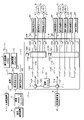
図1は、実施形態1に係る配線分岐箱1の車両における配置状態を示す模式図である。図2は、配線分岐箱1の構成を示すブロック図である。車両の内部には、配線分岐箱1、主蓄電装置2、補機3、負荷5、高圧蓄電装置4、通信装置6、車外通信機7及び副蓄電装置8が設けられている。
(Embodiment 1)
FIG. 1 is a schematic diagram showing an arrangement state of the wiring branch box 1 according to the first embodiment in the vehicle. FIG. 2 is a block diagram showing the configuration of the wiring branch box 1. Inside the vehicle, a wiring branch box 1, a main
主蓄電装置2は、例えば鉛バッテリー等の12Vの直流電源である。主蓄電装置2は、主電源配線11により配線分岐箱1に接続されている。補機3は、例えばDCDCコンバータであり、リチウムイオン電池等の高圧蓄電装置4から印加された直流高圧電圧を12Vに変圧して出力する。補機3と主蓄電装置2とは主電源配線11により並列に接続されており、補機3は主蓄電装置2と同様に主電源配線11により配線分岐箱1に接続されている。主蓄電装置2及び補機3には、主電源配線11から分岐された電源配線によって、駆動モータ等の負荷5が接続されおり、当該負荷5は、主蓄電装置2又は補機3から供給された電力によって駆動する。
The main
副蓄電装置8は、例えば鉛バッテリー等の12Vの直流電源である。副蓄電装置8は、副電源配線12により配線分岐箱1に接続されている。
The auxiliary
通信装置6は、後述する複数の操作系主ECU20(Electronic Control Unit)と、例えばCAN(Controller Area Network/登録商標)又はイーサネット(登録商標)ケーブル等により通信可能に接続されており、接続される複数の操作系主ECU20を含む各種ECU間での通信を中継するものであり、例えばゲートウェイと称される中継装置である。
The
通信装置6には、配線分岐箱1が例えばイーサネット(登録商標)ケーブル等の通信配線10により通信可能に接続されている。更に通信装置6には、例えばシリアルケーブル等のハーネスにより車外通信機7と通信可能に接続されている。
The wiring branch box 1 is communicably connected to the
車外通信機7には、車外の外部サーバ(図示せず)と無線通信するためのアンテナ71と、ハーネス等により接続されている。車外通信機7は、例えば5G、4G又はLTE等の所定の広域通信規格を用いて、車外の外部サーバと無線通信するものであり、例えばTCU(Telematics Communication Unit)と称される通信デバイスである。
The
車両の内部には、各種車載装置(図示せず)を制御するECUが設けられている。当該ECUは、車両の走行、停止及び操舵等を制御する操作系ECU(操作系主ECU20、操作系副ECU25)、及び車両の自動運転機能を制御する自動運転系ECU(判断系主ECU22、認知系主ECU21、判断系副ECU24、認知系副ECU23)を含む。認知系主ECU21及び認知系副ECU23は、接続される各種センサー9が取得又は検出したデータに基づき、車外に位置する障害物等の物標を認知する。判断系主ECU22及び判断系副ECU24は、物標の認知結果に基づき、車両の運転に関する判断を行う。操作系主ECU20及び操作系副ECU25は、当該判断結果に基づき、車両の走行、停止又は操舵等の操作に関するアクチュエータの動作を制御する。
Inside the vehicle, an ECU that controls various in-vehicle devices (not shown) is provided. The ECU is an operation system ECU (operation system
自動運転系ECU(判断系主ECU22、認知系主ECU21、判断系副ECU24、認知系副ECU23)及び操作系副ECU25は、例えばイーサネットケーブル等の通信ケーブル27によって、配線分岐箱1に通信可能に接続されている。詳細は後述するが、配線分岐箱1は接続された自動運転系ECU(判断系主ECU22、認知系主ECU21、判断系副ECU24、認知系副ECU23)、操作系副ECU25及び通信装置6の間での通信を中継する中継器として機能する。通信装置6は車外通信機7と接続しており、自動運転系ECU(判断系主ECU22、認知系主ECU21、判断系副ECU24、認知系副ECU23)及び操作系副ECU25は、配線分岐箱1、通信装置6及び車外通信機7を介して、車外に位置する外部サーバ(図示せず)と通信する。
The automatic operation system ECU (judgment system
自動運転系ECU(判断系主ECU22、認知系主ECU21、判断系副ECU24、認知系副ECU23)及び操作系副ECU25には、主電源配線11又は副電源配線12を介して供給された電力が、配線分岐箱1によって分配される。図1においては、配線分岐箱1と、自動運転系ECU(判断系主ECU22、認知系主ECU21、判断系副ECU24、認知系副ECU23)及び操作系副ECU25とは、通信ケーブル27により接続しているが、図2に示すごとく、電源ケーブル26によっても接続されている。
The power supplied to the automatic operation system ECU (judgment system
認知系主ECU21又は認知系副ECU23には、センサー9がシリアルケーブル等のハーネス(図示せず)により通信可能に接続されている。センサー9は、車外の風景を撮像するCOMSカメラ等の撮像部及び、車外に位置する物標を検出する赤外線センサー、ミリ波レーダー又はLiDAR(Light Detection and Ranging)を含む。当該センサーは、車両の前方、側方及び後方を含む周囲にて、全般に亘って設けられている。各位置夫々に設けられているセンサー9は2つあり、これら2つのセンサー9が同様の機能を有する。当該2つのセンサー9の内、一方のセンサー9は認知系主ECU21に接続されており、他方のセンサー9は認知系副ECU23に接続されている。
A
当該2つのセンサー9の機能は同様としたが、全く同じ機能又は同じ仕様のセンサー9である場合に限定されない。例えば当該2つのセンサー9において、一方のセンサー9はCOMSカメラであり、他方もセンサー9はLiDARとしてもよい。当該2つのセンサー9が取得又は検出するデータは異なるものとしつつ、これらセンサー9夫々に接続される認知系主ECU21又は認知系副ECU23が、取得又は検出するデータに基づき、車外に位置する障害物等の物標を認識するものであってもよい。
The functions of the two
操作系主ECU20は、負荷5と同様に主電源配線11から分岐された電源配線によって、主蓄電装置2及び補機3に接続されおり、主蓄電装置2又は補機3から供給された電力によって駆動する。操作系主ECU20は、例えばイーサネットケーブル等により通信装置6と通信可能に接続されている。通信装置6に接続される複数の操作系主ECU20は、通信装置6を介して他のECU又は、通信装置6及び車外通信機7を介して車外の外部サーバと通信する。
The operation system
このように構成された車両は、手動運転の車両に自動運転機能を追加実装した態様を示すものである。すなわち、当初、当該車両は、手動運転の車両として構成されており、当該手動運転の車両の走行、停止及び操舵等を制御する操作系主ECU20が搭載されていた。そして、手動運転の車両に自動運転機能を追加実装するにあたり、自動運転系ECU(判断系主ECU22、認知系主ECU21、判断系副ECU24、認知系副ECU23)及び、当該自動運転系ECUの内、特に認知系主ECU21又は認知系副ECU23に接続される各種センサー9が追加搭載されたものである。
The vehicle configured in this way shows an embodiment in which an automatic driving function is additionally implemented in a manually driven vehicle. That is, initially, the vehicle was configured as a manually driven vehicle, and was equipped with an operation system
車両が自動運転機能を発揮して走行、停止及び操舵等を行うにあたり、自動運転系ECUを主ECU(認知系主ECU21、判断系主ECU22)及び副ECU(認知系副ECU23、判断系副ECU24)にて二重化して冗長化するに加え、電源についても副蓄電装置8を追加搭載している。更に、当初の手動運転の車両にて搭載されている操作系主ECU20についても冗長化を図るべく、操作系副ECU25を追加搭載している。このように手動運転の車両に自動運転機能を追加実装するにあたり、自動運転系ECU及び操作系ECUを二重化し、当該自動運転系ECU及び操作系ECUへの電力の供給源(主蓄電装置2、副蓄電装置8)を二重化して冗長化することにより、自動運転機能の可用性を向上させることができる。
When the vehicle exerts its automatic driving function to run, stop, steer, etc., the automatic driving system ECU is the main ECU (cognitive system
配線分岐箱1は、主電力入力端子101、主電力線102、複数の主電力出力端子104、副電力入力端子111、副電力線112、複数の副電力出力端子114、接続線120、及び遮断ユニット121を含む。
The wiring branch box 1 includes a main
主電力入力端子101は、主電源配線11が接続される電源端子又はソケットである。
主電力入力端子101には、主電力線102が接続されている。主電力線102は、例えばケーブル又はバスバーにより構成される。主電源配線11を介して接続される主蓄電装置2又は補機3から流れる電流は、主電力入力端子101を介して主電力線102に流れる。
The main
A
主電力出力端子104は、主ECU(認知系主ECU21、判断系主ECU22)に電力を供給する電源ケーブル26が接続される電源端子又はソケットである。
The main
主電力線102は、ケーブル又はバスバーからなり、主電力分岐点103において、対応する複数の主電力出力端子104の個数に応じて分岐される。従って、主電力線102は主電力分岐点103にて分岐され、分岐した主電力線102夫々は、対応する主電力出力端子104夫々に接続してある。
The
主電力分岐点103と、複数の主電力出力端子104夫々との間には、ヒューズ130が設けられている。ヒューズ130は、分岐した主電力線102夫々の径サイズ又は許容電流値に応じて、溶断特性等の定格値が設定される。
A
副電力入力端子111は、副電源配線12が接続される電源端子又はソケットである。
副電力入力端子111には、副電力線112が接続されている。副電力線112は、例えばケーブル又はバスバーにより構成される。副電源配線12を介して接続される副蓄電装置8から流れる電流は、副電力入力端子111を介して副電力線112に流れる。
The sub
An
副電力出力端子114は、副ECU(認知系副ECU23、判断系副ECU24、操作系副ECU25)に電力を供給する電源ケーブル26が接続される電源端子又はソケットである。
The
副電力線112は、ケーブル又はバスバーからなり、副電力分岐点113において、対応する複数の副電力出力端子114の個数に応じて分岐される。従って、副電力線112は副電力分岐点113にて分岐され、分岐した副電力線112夫々は、対応する副電力出力端子114夫々に接続してある。
The
副電力分岐点113と、複数の副電力出力端子114夫々との間には、ヒューズ130が設けられている。ヒューズ130は、分岐した副電力線112夫々の径サイズ又は許容電流値に応じて、溶断特性等の定格値が設定される。
A
配線分岐箱1は、主電力入力端子101、主電力線102及び複数の主電力出力端子104による主電力系統と、副電力入力端子111、副電力線112及び複数の副電力出力端子114による副電力系統との2つの電力系統を備える。当該2つの電力系統夫々には、異なる電力の供給源(主蓄電装置2及び補機3、又は副蓄電装置8)が、接続されている。
すなわち、主電力系統には主蓄電装置2及び補機3が接続される。副電力系統には、副蓄電装置8が接続される。従って、いずれか一方の電力の供給源が故障した場合であっても、他方の電力の供給源が接続されている電力系統のECUへ電力を継続して供給することができる。
The wiring branch box 1 includes a main power system having a main
That is, the main
主電力入力端子101と副電力入力端子111とは、接続線120によって電気的に接続してある。接続線120は、主電力線102及び副電力線112と同様にケーブル又はバスバーにより構成される。主電力入力端子101及び副電力入力端子111が接続線120によって電気的に接続することにより、主電源配線11を介して主蓄電装置2又は補機3から供給された電力と、副電源配線12を介して副蓄電装置8から供給された電力とを、主電力線102又は副電力線112を介して、主ECU及び副ECUに供給することができる。従って、主蓄電装置2及び補機3、又は副蓄電装置8の一方の電力の供給源が故障し電力を供給できない場合であっても、他方の電力の供給源から、主ECU及び副ECUの双方に電力を供給することができる。例えば、主蓄電装置2及び補機3が故障した場合、副蓄電装置8から供給された電力を接続線120及び主電力線102(主電力系統)を介して主ECUにも供給することができる。
The main
接続線120には、主電力入力端子101と副電力入力端子111との接続を遮断する遮断ユニット121が設けられている。詳細は後述する。
The
配線分岐箱1は更に、通信装置側通信ポート140、複数の主ECU側通信ポート153、複数の副ECU側通信ポート163、主通信分岐部152、副通信分岐部162、及び主通信分岐部152と副通信分岐部162とを接続するカスケード部170を含む。
The wiring branch box 1 further includes a communication device
通信装置側通信ポート140は、例えば100BASE-T1又は1000BASE-T1等のイーサネットの規格に対応したコネクタ形状の通信ポートであり、イーサネットによる通信における入出力インターフェイスとして機能する。通信装置側通信ポート140を介して、配線分岐箱1は、通信装置6と例えばイーサネットケーブルによる通信配線10によって接続してある。
The communication device
主ECU側通信ポート153は、通信装置側通信ポート140と同様に、例えば100BASE-T1又は1000BASE-T1等のイーサネットの規格に対応したコネクタ形状の通信ポートであり、イーサネットによる通信における入出力インターフェイスとして機能する。主ECU側通信ポート153を介して、配線分岐箱1は、主ECU(認知系主ECU21、判断系主ECU22)と例えばイーサネットケーブルによる通信ケーブル27によって接続してある。
Similar to the communication device
主通信分岐部152は、主通信線151によって通信装置側通信ポート140と接続してある。主通信分岐部152は、通信装置側通信ポート140と接続する主通信線151を、複数の主ECU側通信ポート153の個数に対応して分岐する。すなわち主通信分岐部152によって分岐された主通信線151夫々は、対応する複数の主ECU側通信ポート153夫々に接続してある。このように主通信分岐部152によって、通信装置側通信ポート140に接続された通信配線10を分岐する分岐回路が構成される。
The main
主通信分岐部152は、例えばレイヤー2スイッチ又はレイヤー3スイッチのイーサスイッチにより構成されるものであってもよい。又は、通信装置側通信ポート140、複数の主ECU側通信ポート153、主通信分岐部152、及び各主ECU側通信ポート153と主通信分岐部152とを接続する主通信線151により、イーサスイッチを構成するものであってもよい。この場合、主通信分岐部152は、イーサスイッチの制御を行うマイコンに相当し、主通信線151はイーサスイッチ内に設けられる内部バスに相当する。主通信分岐部152をイーサスイッチにより構成することにより、レイヤー2スイッチの場合は主ECUのMACアドレス又は、レイヤー3スイッチの場合は主ECUのIPアドレスによるスイッチング制御を行うことができる。主通信分岐部152は、例えば各主ECU側通信ポート153における通信の異常検知を行い、異常検知した主ECU側通信ポート153を遮断するものであってもよい。当該主ECU側通信ポート153を遮断した場合であっても、主ECU側通信ポート153に接続される主ECUと同様の機能を有する副ECUによって、車両の走行等に必要な機能を発揮することができる。
The main
副ECU側通信ポート163は、主ECU側通信ポート153と同様に、例えば100BASE-T1又は1000BASE-T1等のイーサネットの規格に対応したコネクタ形状の通信ポートであり、イーサネットによる通信における入出力インターフェイスとして機能する。副ECU側通信ポート163を介して、配線分岐箱1は、副ECU(認知系副ECU23、判断系副ECU24、操作系副ECU25)と、例えばイーサネットケーブルによる通信ケーブル27によって接続してある。
Like the main ECU
副通信分岐部162と主通信分岐部152とは、カスケード部170によって接続されている。カスケード部170は、例えば副通信分岐部162が備えるカスケードポートによって構成される。カスケード部170と主通信分岐部152とを主通信線151にて接続し、カスケード部170と副通信分岐部162とを副通信線161にて接続することにより、副通信分岐部162及び主通信分岐部152は、接続してある。副通信分岐部162は、副通信線161、カスケード部170及び主通信分岐部152を介して、通信装置側通信ポート140と接続してある。
The
副通信分岐部162は、副通信線161を、複数の副ECU側通信ポート163の個数に対応して分岐する。すなわち副通信分岐部162によって分岐された副通信線161夫々は、対応する複数の副ECU側通信ポート163夫々に接続してある。このように副通信分岐部162によって、通信装置側通信ポート140に接続された通信配線10を分岐する分岐回路が構成される。
The
副通信分岐部162は、例えばレイヤー2スイッチ又はレイヤー3スイッチのイーサスイッチにより構成されるものであってもよい。又は、カスケード部170、複数の副ECU側通信ポート163、副通信分岐部162、及び各副ECU側通信ポート163と副通信分岐部162とを接続する副通信線161により、イーサスイッチを構成するものであってもよい。この場合、副通信分岐部162は、イーサスイッチの制御を行うマイコンに相当し、副通信線161はイーサスイッチ内に設けられる内部バスに相当する。副通信分岐部162をイーサスイッチにより構成することにより、レイヤー2スイッチの場合は副ECUのMACアドレス又は、レイヤー3スイッチの場合は副ECUのIPアドレスによるスイッチング制御を行うことができる。副通信分岐部162は、例えば各副ECU側通信ポート163における通信の異常検知を行い、異常検知した副ECU側通信ポート163を遮断するものであってもよい。当該副ECU側通信ポート163を遮断した場合であっても、副ECU側通信ポート163に接続される副ECUと同様の機能を有する主ECUによって、車両の走行等に必要な機能を発揮することができる。
The
配線分岐箱1は、主通信分岐部152及び複数の主ECU側通信ポート153による主通信系統と、副通信分岐部162及び複数の副ECU側通信ポート163による副通信系統との2つの通信系統を備える。主通信系統には主ECUが接続され、副通信系統には副ECUが接続される。主ECU及び、主ECU夫々に対応して同様の機能を有する副ECU夫々が、配線分岐箱1に通信可能に接続され、主通信系統の主ECU及び副通信系統の副ECUによって二重化し、冗長化を図ることができる。従って、主通信系統又は副通信系統のいずれか一方の通信系統にて通信異常が発生した場合であっても、他方の通信系統に接続されているECU(主ECU又は副ECU)によって、自動運転機能を継続することができる。
The wiring branch box 1 has two communication systems, one is a main communication system with a main
主ECU側通信ポート153及び主電力出力端子104には、主ECU(認知系主ECU21、判断系主ECU22)が接続される。すなわち、主ECU側通信ポート153と主ECUとは、通信ケーブル27により接続され、主ECUは配線分岐箱1を介して他のECUと通信する。配線分岐箱1は、これらECU間の通信を中継する。主電力出力端子104と主ECUとは、電源ケーブル26により接続され、主ECUには、配線分岐箱1を介して電力が供給(分配)される。
The main ECU (cognitive system
副ECU側通信ポート163及び副電力出力端子114には、副ECU(認知系副ECU23、判断系副ECU24、操作系副ECU25)が接続される。すなわち、副ECU側通信ポート163と副ECUとは、通信ケーブル27により接続され、副ECUは配線分岐箱1を介して他のECUと通信する。配線分岐箱1は、これらECU間の通信を中継する。副電力出力端子114と副ECUとは、電源ケーブル26により接続され、副ECUには、配線分岐箱1を介して電力が供給(分配)される。
Sub-ECUs (
このように構成された配線分岐箱1を用いることにより、特に手動運転の車両に自動運転機能を追加実装した場合、追加搭載される各ECUを二重化して冗長化するための分岐及び配策を集約し、追加搭載される各ECUに接続する電源ケーブル26及び通信ケーブル27の配策を効率的に行うことができる。
By using the wiring branch box 1 configured in this way, especially when the automatic driving function is additionally mounted on a manually operated vehicle, branching and arrangement measures for duplicating and making each ECU additionally mounted redundant can be provided. It is possible to efficiently arrange the
追加搭載される各ECUに対し、電力線(主電力線102、副電力線112)及び通信線(主通信線151、副通信線161)を二重化、すなわち電力及び通信において主系統と副系統を備えることにより、電力の供給及び通信の担保における冗長化を図り、自動運転機能の障害耐力又は可用性を向上させることができる。なお、図2及び後述する図4の図面表記上、主系統において、紙面上にて上側に位置する一系統にのみ符号を付し、他は省略してある。同様に副系統において、紙面上にて上側に位置する一系統にのみ符号を付し、他は省略してある。
By duplicating the power line (
各主ECU夫々に対応する主ECU側通信ポート153及び主電力出力端子104は、これらが一体化した複合コネクタとして構成されているものであってもよい。すなわち、配線分岐箱1は、主ECU側通信ポート153及び主電力出力端子104夫々が有する複数の電力端子又は通信端子を組み合わせ、ひとつのコネクタ内に混在させた複合コネクタ(ハイブリッドコネクタ)を備えるものであってもよい。同様に、各副ECU夫々に対応する副ECU側通信ポート163及び副電力出力端子114は、これらが一体化した複合コネクタ(ハイブリッドコネクタ)として構成されているものであってもよい。主ECU側通信ポート153及び主電力出力端子104、又は副ECU側通信ポート163及び副電力出力端子114を複合コネクタ(複合主コネクタ、複合副コネクタ)として構成することにより、自動運転機能を追加実装するにあたり、主ECU及び副ECUの追加搭載を簡易に行うことができ、自動運転機能の追加実装に要する工数を削減することができる。
The main ECU
図3は、遮断ユニット121(切り離し部)構成を示すブロック図である。遮断ユニット121は、リレー124、異常検出部122及び制御部123を含む。
FIG. 3 is a block diagram showing the configuration of the cutoff unit 121 (separation portion). The
遮断ユニット121は、接続線120の異常を検出した場合、接続線120を遮断、すなわち接続線120によって接続される主電力入力端子101及び副電力入力端子111を遮断して切り離すものであり、切り離し部に相当する。
When the
リレー124は、接続線120に設けられており、例えば、常時オンとするb接点リレーである。
The
異常検出部122は、接続線120に流れる電流値を検出するホール素子等からなる電流センサー、接続線120における対接地電圧を検出するシャント抵抗等からなる電圧センサー、又は接続線120の温度(ジュール熱)を検出するサーミスタ等からなる温度センサーを含み、接続線120における電気的状態量を検出するものである。異常検出部122は、リレー124の両端における電気的状態量を検出するように、リレー124の両端夫々に異常検出部122のセンサーを配置してある。このようにセンサーを配置することで、リレー124の両端の電位差を検出することができる。又、リレー124の両端における電気的状態量を検出することにより、リレー124をオフにした後、主電力入力端子101側の電気的状態量、及び副電力入力端子111側の電気的状態量の双方の電気的状態量を取得することができる。なお、異常検出部122は、リレー124のいずれか一旦側の電気的状態量を検出するものであってもよい。
The
制御部123は、MPU(microprocessor unit)及びメモリを備えたマイコン等によって構成される。制御部123は、異常検出部122が検出した検出値に基づき接続線120における異常の有無を判定し、異常が有(異常が発生した)と判定した場合、リレー124をオフする。
The
主電力入力端子101には、主蓄電装置2又は補機3から出力された電圧が印加される。副電力入力端子111には、副蓄電装置8から出力された電圧が印加される。主電力入力端子101と副電力入力端子111とを接続する接続線120には、主電力入力端子101及び副電力入力端子111の電位差に応じて電流が流れる。例えば、主電力線102にて地絡が発生した場合、主電力入力端子101の電位は0V(グランドの基準電位)となるため、副電力入力端子111からも接続線120を介して主電力線102に大電流が流れるものとなる。従って、制御部123は、異常検出部122からの検出値に基づき、接続線120に所定値以上の大電流が流れた場合、当該大電流により発生したジュール熱により所定の温度以上となった場合、又は接続線120の電圧が略0V等の所定値以下となった場合、主電力線102又は副電力線112にて異常が発生したと判定し、リレー124をオフにする。リレー124をオフにすることにより、主電力入力端子101と副電力入力端子111とは、切断される。すなわち、主電力系統と副電力系統とが、分断される。主電力入力端子101及び副電力入力端子111が切断されることにより、正常な電力系統に接続されるECU(主ECU又は副ECU)には、電力が供給される。
The voltage output from the main
異常となった主電力線102又は副電力線112には、大電流が流れるが、主蓄電装置2及び副蓄電装置8の負極側にはヒューズ(図示せず)が設けられており、当該ヒューズが溶解することにより、異常となった主電力線102又は副電力線112に大電流が流れることは、中断される。このように遮断ユニット121を設けることにより、主電力線102又は副電力線112に異常が発生した場合であっても、異常が発生した側に接続される主蓄電装置2又は副蓄電装置8のヒューズが溶解するよりも速く、主電力入力端子101と副電力入力端子111とを切り離すことができる。主電力入力端子101と副電力入力端子111とを切り離すことにより、異常が発生していない側の電力系統に接続されるECU(主ECU又は副ECU)への電力の供給を継続することができる。リレー124は、b接点リレーによる機械式リレーとしたが、これに限定されない。リレー124は、FET又はIGBT等の半導体リレーであってもよい。
A large current flows through the
図1に示すごとく、配線分岐箱1は、主蓄電装置2と副蓄電装置8との間に配され、車両の前後における中央部に位置するように設けられている。主蓄電装置2は車両の前部に配置されており、自動運転機能を追加実装するにあたり併せて追加搭載される副蓄電装置8は、車両の後部に配置されるものとなる。配線分岐箱1を主蓄電装置2と副蓄電装置8との間に配することにより、主蓄電装置2及び副蓄電装置8と、配線分岐箱1との間の電源配線(主電源配線11、副電源配線12)を効率的に配策することができる。車両の前部にある主蓄電装置2と後部にある副蓄電装置8との間に配線分岐箱1を配することにより、配線分岐箱1は車両の前後における中央部に位置するものとなる。車両の中央部として、例えば車室内コンソール内、インパネ内、又はシートの下方に、配線分岐箱1が設けられるものであってもよい。車両の前後における中央部に配線分岐箱1を設けることにより、車外からの衝撃が加えられた場合であっても、配線分岐箱1への影響を低減し、当該衝撃に対する耐力を向上させることができる。
As shown in FIG. 1, the wiring branch box 1 is arranged between the main
自動運転機能を追加実装するにあたり併せて追加搭載される認知系センサー等の各種センサー9、自動運転系ECU(認知系主ECU21、判断系主ECU22、認知系副ECU23、判断系副ECU24)及び操作系副ECU25は、用途又は機能等に基づき、車両の内部に適宜配置されるものとなる。これに対し、車両の中央部に配線分岐箱1を設けることにより、追加搭載した各種センサー9及びECU(自動運転系ECU、操作系副ECU25)夫々からの距離の均等化を図ることに寄与することができる。従って、追加搭載した各種センサー9及びECUと、配線分岐箱1との間における電源ケーブル26及び通信ケーブル27のケーブル長を短縮する等、配策を効率的に行うことができる。
配線分岐箱1は、手動運転の車両に自動運転機能を追加実装するにあたり、追加搭載した自動運転系ECU(判断系主ECU22、認知系主ECU21、判断系副ECU24、認知系副ECU23)及び操作系副ECU25のため、配策する電源配線(主電源配線11、副電源配線12)及び通信配線10を集約する。当該電源配線(主電源配線11、副電源配線12)及び通信配線10を配線分岐箱1に集約させて分岐することにより、電源配線(主電源配線11、副電源配線12)及び通信配線10の配策を簡易化させ、自動運転機能の追加実装に要する工数を削減することができる。又、配線分岐箱1を用いることにより、電源配線及び通信配線10を別個に集約させて分岐するに比べ、これら配線(ハーネス)の接続箇所を少なくし、又ユニット数を低減でき、部品点数の削減、低コスト化又は車両での作業工程の短縮化を図ることができる。
The wiring branch box 1 is additionally mounted with an automated driving system ECU (judgment system
配線分岐箱1は、手動運転の車両に自動運転機能を追加実装するにあたり、二重化して冗長化するための主ECU及び副ECUに対応するように、電力及び通信にて主系統及び副系統を備える。これら主系統及び副系統により、電源及び通信の冗長化を図ることにより、自動運転機能を追加実装の工数を低減すると共に、自動運転機能の可用性の向上及び信頼性の担保に寄与することができる。 The wiring branch box 1 has a main system and a sub system by electric power and communication so as to correspond to the main ECU and the sub ECU for duplicating and making redundant when the automatic driving function is additionally mounted on the manually operated vehicle. Be prepared. By making the power supply and communication redundant by using these main system and sub system, it is possible to reduce the man-hours for additionally mounting the automatic operation function, and to contribute to the improvement of the availability of the automatic operation function and the guarantee of reliability. ..
遮断ユニット121を設けることにより、いずれかの電力系統において地絡等の異常が発生した場合であっても、主電力入力端子101と副電力入力端子111との接続を遮断し、異常が発生していない電力系統に接続されているECU(主ECU又は副ECU)への電力の供給を継続することができる。
By providing the
本実施形態にて、車両は、手動運転の車両に自動運転機能を追加実装した態様を示すものとしたが、これに限定されない。車両は、自動運転の車両として製造されたものを含む。配線分岐箱1は、このように製造段階の当初より、自動運転機能を有する車両に適用することができる。配線分岐箱1を、製造段階の当初より自動運転機能を有する車両に適用する場合、操作系主ECU20は、主ECU(認知系主ECU21、判断系主ECU22)と同じ電力及び通信の系統となる主系統に接続されるものであってもよい。自動運転系ECU(判断系主ECU22、認知系主ECU21、判断系副ECU24、認知系副ECU23)及び操作系ECU(操作系主ECU20、操作系副ECU25)を含む自動運転機能を発揮するにあたり必要なECUを配線分岐箱1に接続することにより、これら自動運転系ECU及び操作系ECUに必要な電力供給及び通信に関する配策を効率的に行うことができる。
In the present embodiment, the vehicle shows an embodiment in which an automatic driving function is additionally mounted on a manually driven vehicle, but the vehicle is not limited to this. Vehicles include those manufactured as self-driving vehicles. As described above, the wiring branch box 1 can be applied to a vehicle having an automatic driving function from the beginning of the manufacturing stage. When the wiring branch box 1 is applied to a vehicle having an automatic driving function from the beginning of the manufacturing stage, the operation system
(実施形態2)
図4は、実施形態2(通信装置側通信ポートを冗長化)に係る配線分岐箱1の構成を示すブロック図である。実施形態2の配線分岐箱1は、通信装置6と接続する通信装置側通信ポート140が、主通信ポート141及び副通信ポート142の2つの通信ポートを含む点で、実施形態1と異なる。
(Embodiment 2)
FIG. 4 is a block diagram showing a configuration of a wiring branch box 1 according to a second embodiment (communication device side communication port is made redundant). The wiring branch box 1 of the second embodiment is different from the first embodiment in that the communication device
配線分岐箱1は、主通信ポート141及び副通信ポート142を備える。主通信ポート141及び副通信ポート142は、実施形態1の通信装置側通信ポート140と同様に、例えば100BASE-T1又は1000BASE-T1等のイーサネットの規格に対応したコネクタ形状の通信ポートであり、イーサネットによる通信における入出力インターフェイスとして機能する。主通信ポート141及び副通信ポート142を介して、配線分岐箱1は、通信装置6とイーサネットケーブルによる通信配線10によって接続してある。
The wiring branch box 1 includes a
主通信分岐部152は、主通信線151によって主通信ポート141と接続してある。副通信分岐部162は、副通信線161によって副通信ポート142と接続してある。すなわち、主通信分岐部152及び副通信分岐部162は、通信装置6に対し並列に接続されている。
The main
主通信分岐部152と複数の主ECU側通信ポート153との接続は、実施形態1と同様である。副通信分岐部162と複数の副ECU側通信ポート163との接続は、実施形態1と同様である。
The connection between the main
このような構成とすることにより、主通信分岐部152と副通信分岐部162とを接続するカスケード部170を不要とすることができる。又、主通信分岐部152及び複数の主ECU側通信ポート153による主通信系統と、副通信分岐部162及び複数の副ECU側通信ポート163による副通信系統とを、通信装置6との接続レベルから分離して、完全に別系統することができる。従って、配線分岐箱1と通信装置6との通信においても二重化して冗長化することができる。すなわち、主通信分岐部152が故障して通信不可となった場合であっても、副ECUは副通信分岐部162を介して通信装置6との通信を行うことができ、当該通信装置6及び車外通信機7を介して車外の外部サーバと通信することができる。配線分岐箱1と通信装置6との通信においても二重化して冗長化することにより、主通信系統又は副通信系統に異常が発生した場合であっても、異常が発生していない通信系統に接続された自動運転系ECU(主ECU又は副ECU)と車外の外部サーバとの通信を担保させ、自動運転機能を確実に継続することができる。
With such a configuration, the
主通信分岐部152と副通信分岐部162とを接続するカスケード部170を不要とするとしたが、これに限定されない。主通信分岐部152と副通信分岐部162とは、実施形態1と同様にカスケード部170によって接続されているものであってもよい。主通信分岐部152と副通信分岐部162とをカスケード部170により接続することにより、通信装置6を介することなく、主通信分岐部152に接続される主ECUと、副通信分岐部162に接続される副ECUとの間の通信を、配線分岐箱1内にて中継することができる。
Although it is said that the
今回開示された実施形態はすべての点で例示であって、制限的なものではないと考えられるべきである。本発明の範囲は、上記した意味ではなく、特許請求の範囲によって示され、特許請求の範囲と均等の意味及び範囲内でのすべての変更が含まれることが意図される。 The embodiments disclosed this time should be considered to be exemplary in all respects and not restrictive. The scope of the present invention is indicated by the scope of claims, not the above-mentioned meaning, and is intended to include all modifications within the meaning and scope equivalent to the scope of claims.
1 配線分岐箱
101 主電力入力端子(電力入力端子)
102 主電力線(配線、電力線)
103 主電力分岐点
104 主電力出力端子(電力出力端子)
111 副電力入力端子
112 副電力線(配線、電力線)
113 副電力分岐点
114 副電力出力端子(電力出力端子)
120 接続線
121 遮断ユニット(切り離し部)
122 異常検出部
123 制御部
124 リレー
130 ヒューズ
140 通信装置側通信ポート
141 主通信ポート
142 副通信ポート
151 主通信線(配線、通信線)
152 主通信分岐部
153 主ECU側通信ポート(ECU側通信ポート)
161 副通信線(配線、通信線)
162 副通信分岐部
163 副ECU側通信ポート(ECU側通信ポート)
170 カスケード部
2 主蓄電装置(蓄電装置)
3 補機
4 高圧蓄電装置
5 負荷
6 通信装置
7 車外通信機
71 アンテナ
8 副蓄電装置
9 センサー
10 通信配線
11 主電源配線
12 副電源配線
20 操作系主ECU
21 認知系主ECU(自動運転系ECU、主ECU、ECU)
22 判断系主ECU(自動運転系ECU、主ECU、ECU)
23 認知系副ECU(自動運転系ECU、副ECU、ECU)
24 判断系副ECU(自動運転系ECU、副ECU、ECU)
25 操作系副ECU(ECU)
26 電源ケーブル
27 通信ケーブル
1
102 Main power line (wiring, power line)
103 Main
111 Secondary
113 Secondary
120
122
152
161 Sub-communication line (wiring, communication line)
162
170
3
21 Cognitive system main ECU (automatic operation system ECU, main ECU, ECU)
22 Judgment system main ECU (automatic operation system ECU, main ECU, ECU)
23 Cognitive system sub-ECU (automatic operation system ECU, sub-ECU, ECU)
24 Judgment system sub-ECU (automatic operation system ECU, sub-ECU, ECU)
25 Operation system sub-ECU (ECU)
26
Claims (7)
前記ECUに電力を供給する蓄電装置に接続される電力入力端子と、
前記電力入力端子から入力された電力を前記複数のECU夫々に出力する複数の電力出力端子と、
前記ECUと通信する通信装置に接続される通信装置側通信ポートと、
前記複数のECU夫々に接続される複数のECU側通信ポートとを備え、
前記配線は、前記電力入力端子と前記電力出力端子とを接続する電力線及び、前記通信装置側通信ポートと前記ECU側通信ポートとを接続する通信線を含み、
前記電力線は、前記複数の電力出力端子の個数に応じて分岐され、
前記通信線は、前記複数のECU側通信ポートの個数に応じて分岐されており、
前記複数のECUは、複数の自動運転系ECUを含み、
前記複数の自動運転系ECUは、主ECU及び副ECUを含み、
前記電力線及び前記通信線夫々は、前記主ECU及び前記副ECU夫々に対応した系統を有し、
前記通信線は、前記主ECUに対応した系統の主通信線と、前記副ECUに対応した系統の副通信線とを含み、
前記主通信線に接続され、前記主通信線を分岐する主通信分岐部と、
前記副通信線に接続され、前記副通信線を分岐する副通信分岐部とを備え、
前記主通信分岐部及び前記副通信分岐部は、レイヤー2スイッチ又はレイヤー3スイッチとして機能する
配線分岐箱。 It is a wiring branch box that branches the wiring connected to multiple ECUs mounted on the vehicle.
A power input terminal connected to a power storage device that supplies power to the ECU,
A plurality of power output terminals that output the power input from the power input terminals to the plurality of ECUs, respectively.
A communication device-side communication port connected to a communication device that communicates with the ECU,
It is provided with a plurality of ECU-side communication ports connected to each of the plurality of ECUs.
The wiring includes a power line connecting the power input terminal and the power output terminal, and a communication line connecting the communication device side communication port and the ECU side communication port.
The power line is branched according to the number of the plurality of power output terminals.
The communication line is branched according to the number of the plurality of ECU-side communication ports.
The plurality of ECUs include a plurality of automatic driving system ECUs.
The plurality of automatic operation system ECUs include a main ECU and a sub-ECU.
The power line and the communication line each have a system corresponding to each of the main ECU and the sub-ECU.
The communication line includes a main communication line of a system corresponding to the main ECU and a sub communication line of a system corresponding to the sub ECU.
A main communication branch portion connected to the main communication line and branching the main communication line,
It is provided with a sub-communication branch portion that is connected to the sub-communication line and branches the sub-communication line.
The main communication branch and the sub communication branch function as a layer 2 switch or a layer 3 switch.
Wiring branch box.
前記通信線は、前記主ECUに対応した系統の主通信線と、前記副ECUに対応した系統の副通信線とを含み、
前記主電力線は、前記主ECU用の電力出力端子の個数に応じて分岐され、
前記主通信線は、前記主ECU用のECU側通信ポートの個数に応じて分岐され、
前記副電力線は、前記副ECU用の電力出力端子の個数に応じて分岐され、
前記副通信線は、前記副ECU用のECU側通信ポートの個数に応じて分岐されている
請求項1に記載の配線分岐箱。 The power line includes a main power line of a system corresponding to the main ECU and a sub power line of a system corresponding to the sub ECU.
The communication line includes a main communication line of a system corresponding to the main ECU and a sub communication line of a system corresponding to the sub ECU.
The main power line is branched according to the number of power output terminals for the main ECU.
The main communication line is branched according to the number of ECU-side communication ports for the main ECU.
The sub power line is branched according to the number of power output terminals for the sub ECU.
The wiring branch box according to claim 1 , wherein the sub-communication line is branched according to the number of ECU-side communication ports for the sub-ECU.
前記電力線は、前記電力入力端子と前記副電力入力端子との間を接続する接続線を含み、
前記接続線によって、前記主ECU及び前記副ECUへの電力の供給を冗長化する
請求項2に記載の配線分岐箱。 Equipped with an auxiliary power input terminal connected to the auxiliary power storage device
The power line includes a connection line connecting the power input terminal and the sub power input terminal.
The wiring branch box according to claim 2 , wherein the power supply to the main ECU and the sub-ECU is made redundant by the connection line.
前記切り離し部は、前記接続線に異常が生じた場合、前記電力入力端子と前記副電力入力端子とを切り離す
請求項3に記載の配線分岐箱。 The connection line is provided with a disconnection portion for separating the power input terminal and the sub power input terminal.
The wiring branch box according to claim 3 , wherein the disconnection portion disconnects the power input terminal and the sub power input terminal when an abnormality occurs in the connection line.
前記主通信ポートには、前記主通信線が接続され
前記副通信ポートには、前記副通信線が接続される
請求項4に記載の配線分岐箱。 The communication device side communication port includes a main communication port and a sub communication port.
The wiring branch box according to claim 4 , wherein the main communication line is connected to the main communication port, and the sub communication line is connected to the sub communication port.
前記操作系副ECUは、前記副ECUと同じ系統の前記電力線及び前記通信線に接続される
請求項1から請求項5のいずれか一つに記載の配線分岐箱。 The plurality of ECUs include an operation system main ECU and an operation system sub-ECU.
The wiring branch box according to any one of claims 1 to 5 , wherein the operation system sub-ECU is connected to the power line and the communication line of the same system as the sub-ECU.
請求項3又は請求項4に記載の配線分岐箱。 The wiring branch box according to claim 3 or 4 , which is arranged between the power storage device and the sub power storage device and is provided so as to be located at the center of the vehicle.
Priority Applications (4)
| Application Number | Priority Date | Filing Date | Title |
|---|---|---|---|
| JP2018169086A JP7070260B2 (en) | 2018-09-10 | 2018-09-10 | Wiring branch box |
| PCT/JP2019/033318 WO2020054380A1 (en) | 2018-09-10 | 2019-08-26 | Wiring junction box |
| US17/274,875 US11731571B2 (en) | 2018-09-10 | 2019-08-26 | Wiring junction box |
| CN201980055330.1A CN112867634A (en) | 2018-09-10 | 2019-08-26 | Distribution branch box |
Applications Claiming Priority (1)
| Application Number | Priority Date | Filing Date | Title |
|---|---|---|---|
| JP2018169086A JP7070260B2 (en) | 2018-09-10 | 2018-09-10 | Wiring branch box |
Publications (3)
| Publication Number | Publication Date |
|---|---|
| JP2020040504A JP2020040504A (en) | 2020-03-19 |
| JP2020040504A5 JP2020040504A5 (en) | 2021-05-20 |
| JP7070260B2 true JP7070260B2 (en) | 2022-05-18 |
Family
ID=69777525
Family Applications (1)
| Application Number | Title | Priority Date | Filing Date |
|---|---|---|---|
| JP2018169086A Active JP7070260B2 (en) | 2018-09-10 | 2018-09-10 | Wiring branch box |
Country Status (4)
| Country | Link |
|---|---|
| US (1) | US11731571B2 (en) |
| JP (1) | JP7070260B2 (en) |
| CN (1) | CN112867634A (en) |
| WO (1) | WO2020054380A1 (en) |
Families Citing this family (2)
| Publication number | Priority date | Publication date | Assignee | Title |
|---|---|---|---|---|
| JP7420769B2 (en) * | 2021-07-05 | 2024-01-23 | 矢崎総業株式会社 | electrical circuit board |
| WO2023095909A1 (en) * | 2021-11-29 | 2023-06-01 | 日産自動車株式会社 | Power supply system and method for controlling power supply system |
Citations (4)
| Publication number | Priority date | Publication date | Assignee | Title |
|---|---|---|---|---|
| JP2011066239A (en) | 2009-09-17 | 2011-03-31 | Autonetworks Technologies Ltd | Ecu concentration housing box |
| JP2011108955A (en) | 2009-11-19 | 2011-06-02 | Autonetworks Technologies Ltd | Ecu centralized storage box |
| JP2014094660A (en) | 2012-11-09 | 2014-05-22 | Yazaki Corp | Wiring structure of electrical junction box for vehicle |
| WO2017051736A1 (en) | 2015-09-24 | 2017-03-30 | 株式会社オートネットワーク技術研究所 | Onboard power-source device |
Family Cites Families (10)
| Publication number | Priority date | Publication date | Assignee | Title |
|---|---|---|---|---|
| JP2000016200A (en) * | 1998-07-03 | 2000-01-18 | Hitachi Ltd | Power supply control device for vehicle |
| JP6116535B2 (en) * | 2014-09-29 | 2017-04-19 | 矢崎総業株式会社 | Power supply box device for vehicles |
| JP6597371B2 (en) * | 2016-02-17 | 2019-10-30 | 株式会社オートネットワーク技術研究所 | In-vehicle power supply switch device and in-vehicle power supply device |
| JP6540565B2 (en) * | 2016-03-16 | 2019-07-10 | 株式会社オートネットワーク技術研究所 | Power supply system for vehicle, drive system for vehicle |
| CN205706212U (en) * | 2016-04-08 | 2016-11-23 | 同济大学 | Centralized architecture controller and the electric intelligent automotive electrical system of power supply redundancy |
| CN105857102B (en) * | 2016-04-08 | 2017-12-15 | 同济大学 | The electric intelligent automotive electrical system of centralized architecture controller and redundancy of powering |
| JP6611664B2 (en) * | 2016-04-26 | 2019-11-27 | 三菱電機株式会社 | Automatic operation control device and automatic operation control method |
| CN116101187A (en) * | 2016-06-24 | 2023-05-12 | 矢崎总业株式会社 | Vehicle circuit body |
| US10073456B2 (en) * | 2016-11-17 | 2018-09-11 | GM Global Technology Operations LLC | Automated co-pilot control for autonomous vehicles |
| US10407003B2 (en) * | 2017-02-16 | 2019-09-10 | Ford Global Technologies, Llc | Short-circuit protection for vehicle redundant power architecture |
-
2018
- 2018-09-10 JP JP2018169086A patent/JP7070260B2/en active Active
-
2019
- 2019-08-26 WO PCT/JP2019/033318 patent/WO2020054380A1/en active Application Filing
- 2019-08-26 CN CN201980055330.1A patent/CN112867634A/en active Pending
- 2019-08-26 US US17/274,875 patent/US11731571B2/en active Active
Patent Citations (4)
| Publication number | Priority date | Publication date | Assignee | Title |
|---|---|---|---|---|
| JP2011066239A (en) | 2009-09-17 | 2011-03-31 | Autonetworks Technologies Ltd | Ecu concentration housing box |
| JP2011108955A (en) | 2009-11-19 | 2011-06-02 | Autonetworks Technologies Ltd | Ecu centralized storage box |
| JP2014094660A (en) | 2012-11-09 | 2014-05-22 | Yazaki Corp | Wiring structure of electrical junction box for vehicle |
| WO2017051736A1 (en) | 2015-09-24 | 2017-03-30 | 株式会社オートネットワーク技術研究所 | Onboard power-source device |
Also Published As
| Publication number | Publication date |
|---|---|
| CN112867634A (en) | 2021-05-28 |
| JP2020040504A (en) | 2020-03-19 |
| US20220144192A1 (en) | 2022-05-12 |
| WO2020054380A1 (en) | 2020-03-19 |
| US11731571B2 (en) | 2023-08-22 |
Similar Documents
| Publication | Publication Date | Title |
|---|---|---|
| JP7323662B2 (en) | Circuit body for vehicle | |
| JP6837132B2 (en) | Vehicles with automatic vehicle electrical system and automatic vehicle electrical system | |
| WO2016111340A1 (en) | Automobile power supply device and power box | |
| WO2017187984A1 (en) | Switch device for on-board power supply and on-board power supply system | |
| US20170036622A1 (en) | Power transmission device and vehicle electrical system | |
| CN110271504B (en) | Vehicle power supply system | |
| JP6991347B2 (en) | Battery terminal for vehicle onboard network | |
| KR20190080931A (en) | On-board network having a power divider and at least one power divider | |
| CN110663151B (en) | Vehicle-mounted system | |
| CN109689438B (en) | Relay device | |
| JP7070260B2 (en) | Wiring branch box | |
| CN111231865B (en) | Vehicle-mounted system | |
| CN107959490B (en) | Intelligent switch for automotive applications | |
| JP5730639B2 (en) | Electronic control device for vehicle and electronic control system for vehicle | |
| CN113613957A (en) | Power supply system for a motor vehicle and method for operating a power supply system for a motor vehicle | |
| US20220266779A1 (en) | In-vehicle power supply system and vehicle equipped with same | |
| JP2015217837A (en) | Power supply device for automobile | |
| JP7334614B2 (en) | In-vehicle repeater | |
| WO2016171203A1 (en) | Power supply device and power supply system | |
| US11772585B2 (en) | Wiring system for automobile | |
| US11323861B2 (en) | In-vehicle communication system | |
| CN113165588A (en) | Power distribution device | |
| JP6251572B2 (en) | Electric wiring device for vehicle | |
| JP2019189019A (en) | Power supply system |
Legal Events
| Date | Code | Title | Description |
|---|---|---|---|
| A621 | Written request for application examination |
Free format text: JAPANESE INTERMEDIATE CODE: A621 Effective date: 20201224 |
|
| A521 | Request for written amendment filed |
Free format text: JAPANESE INTERMEDIATE CODE: A523 Effective date: 20210407 |
|
| A131 | Notification of reasons for refusal |
Free format text: JAPANESE INTERMEDIATE CODE: A131 Effective date: 20220125 |
|
| A521 | Request for written amendment filed |
Free format text: JAPANESE INTERMEDIATE CODE: A523 Effective date: 20220310 |
|
| TRDD | Decision of grant or rejection written | ||
| A01 | Written decision to grant a patent or to grant a registration (utility model) |
Free format text: JAPANESE INTERMEDIATE CODE: A01 Effective date: 20220405 |
|
| A61 | First payment of annual fees (during grant procedure) |
Free format text: JAPANESE INTERMEDIATE CODE: A61 Effective date: 20220418 |
|
| R150 | Certificate of patent or registration of utility model |
Ref document number: 7070260 Country of ref document: JP Free format text: JAPANESE INTERMEDIATE CODE: R150 |