WO2020054380A1 - Wiring junction box - Google Patents
Wiring junction box Download PDFInfo
- Publication number
- WO2020054380A1 WO2020054380A1 PCT/JP2019/033318 JP2019033318W WO2020054380A1 WO 2020054380 A1 WO2020054380 A1 WO 2020054380A1 JP 2019033318 W JP2019033318 W JP 2019033318W WO 2020054380 A1 WO2020054380 A1 WO 2020054380A1
- Authority
- WO
- WIPO (PCT)
- Prior art keywords
- ecu
- sub
- communication
- main
- power
- Prior art date
Links
Images


Classifications
-
- B—PERFORMING OPERATIONS; TRANSPORTING
- B60—VEHICLES IN GENERAL
- B60R—VEHICLES, VEHICLE FITTINGS, OR VEHICLE PARTS, NOT OTHERWISE PROVIDED FOR
- B60R16/00—Electric or fluid circuits specially adapted for vehicles and not otherwise provided for; Arrangement of elements of electric or fluid circuits specially adapted for vehicles and not otherwise provided for
- B60R16/02—Electric or fluid circuits specially adapted for vehicles and not otherwise provided for; Arrangement of elements of electric or fluid circuits specially adapted for vehicles and not otherwise provided for electric constitutive elements
- B60R16/023—Electric or fluid circuits specially adapted for vehicles and not otherwise provided for; Arrangement of elements of electric or fluid circuits specially adapted for vehicles and not otherwise provided for electric constitutive elements for transmission of signals between vehicle parts or subsystems
- B60R16/0238—Electrical distribution centers
-
- B—PERFORMING OPERATIONS; TRANSPORTING
- B60—VEHICLES IN GENERAL
- B60R—VEHICLES, VEHICLE FITTINGS, OR VEHICLE PARTS, NOT OTHERWISE PROVIDED FOR
- B60R16/00—Electric or fluid circuits specially adapted for vehicles and not otherwise provided for; Arrangement of elements of electric or fluid circuits specially adapted for vehicles and not otherwise provided for
- B60R16/02—Electric or fluid circuits specially adapted for vehicles and not otherwise provided for; Arrangement of elements of electric or fluid circuits specially adapted for vehicles and not otherwise provided for electric constitutive elements
- B60R16/023—Electric or fluid circuits specially adapted for vehicles and not otherwise provided for; Arrangement of elements of electric or fluid circuits specially adapted for vehicles and not otherwise provided for electric constitutive elements for transmission of signals between vehicle parts or subsystems
- B60R16/0239—Electronic boxes
-
- B—PERFORMING OPERATIONS; TRANSPORTING
- B60—VEHICLES IN GENERAL
- B60R—VEHICLES, VEHICLE FITTINGS, OR VEHICLE PARTS, NOT OTHERWISE PROVIDED FOR
- B60R16/00—Electric or fluid circuits specially adapted for vehicles and not otherwise provided for; Arrangement of elements of electric or fluid circuits specially adapted for vehicles and not otherwise provided for
- B60R16/02—Electric or fluid circuits specially adapted for vehicles and not otherwise provided for; Arrangement of elements of electric or fluid circuits specially adapted for vehicles and not otherwise provided for electric constitutive elements
- B60R16/023—Electric or fluid circuits specially adapted for vehicles and not otherwise provided for; Arrangement of elements of electric or fluid circuits specially adapted for vehicles and not otherwise provided for electric constitutive elements for transmission of signals between vehicle parts or subsystems
- B60R16/0231—Circuits relating to the driving or the functioning of the vehicle
-
- B—PERFORMING OPERATIONS; TRANSPORTING
- B60—VEHICLES IN GENERAL
- B60R—VEHICLES, VEHICLE FITTINGS, OR VEHICLE PARTS, NOT OTHERWISE PROVIDED FOR
- B60R16/00—Electric or fluid circuits specially adapted for vehicles and not otherwise provided for; Arrangement of elements of electric or fluid circuits specially adapted for vehicles and not otherwise provided for
- B60R16/02—Electric or fluid circuits specially adapted for vehicles and not otherwise provided for; Arrangement of elements of electric or fluid circuits specially adapted for vehicles and not otherwise provided for electric constitutive elements
- B60R16/03—Electric or fluid circuits specially adapted for vehicles and not otherwise provided for; Arrangement of elements of electric or fluid circuits specially adapted for vehicles and not otherwise provided for electric constitutive elements for supply of electrical power to vehicle subsystems or for
-
- H—ELECTRICITY
- H02—GENERATION; CONVERSION OR DISTRIBUTION OF ELECTRIC POWER
- H02G—INSTALLATION OF ELECTRIC CABLES OR LINES, OR OF COMBINED OPTICAL AND ELECTRIC CABLES OR LINES
- H02G3/00—Installations of electric cables or lines or protective tubing therefor in or on buildings, equivalent structures or vehicles
- H02G3/02—Details
- H02G3/08—Distribution boxes; Connection or junction boxes
- H02G3/16—Distribution boxes; Connection or junction boxes structurally associated with support for line-connecting terminals within the box
Definitions
- the present disclosure relates to a wiring junction box.
- This application claims the priority based on Japanese Patent Application No. 2018-169086 filed on Sep. 10, 2018, and incorporates all the contents described in the Japanese application.
- the vehicle is equipped with a vehicle power supply such as a power storage device, branches a power line from the vehicle power supply, and supplies power to a vehicle-mounted device (load) such as an ECU (Electronic Control Unit) via the branched power line.
- a vehicle power supply such as a power storage device
- a vehicle-mounted device such as an ECU (Electronic Control Unit) via the branched power line.
- the electric connection box for a vehicle of Patent Literature 1 includes a power supply terminal connected to a power supply for a vehicle, a relay connected to the power supply terminal, and an electric wire located at a rear stage of the relay and branched into four systems. I have. A load is connected to each of the four branched wires, and power from a vehicle power supply is distributed and supplied to each of these four loads.
- a wiring branch box is a wiring branch box that branches wiring connected to a plurality of ECUs mounted on a vehicle, and a power input terminal connected to a power storage device that supplies power to the ECU.
- a plurality of power output terminals for outputting power input from the power input terminal to each of the plurality of ECUs; a communication device-side communication port connected to a communication device communicating with the ECU; A plurality of ECU-side communication ports connected to the power supply line, and the wiring connects a power line connecting the power input terminal and the power output terminal, and connects the communication device-side communication port and the ECU-side communication port.
- a communication line is included, the power line is branched according to the number of the plurality of power output terminals, and the communication line is branched according to the number of the plurality of ECU-side communication ports.
- FIG. 3 is a block diagram illustrating a configuration of a blocking unit (disconnecting unit). It is a block diagram which shows the structure of the wiring branch box which concerns on Embodiment 2 (communication device side communication port is made redundant).
- the present disclosure has been made in view of such circumstances, and has as its object to provide a wiring branch box corresponding to a measure such as branching of a power line and a communication line.
- a wiring branch box is a wiring branch box that branches wiring connected to a plurality of ECUs mounted on a vehicle, and is connected to a power storage device that supplies power to the ECU.
- a plurality of ECU-side communication ports connected to each of the ECUs, wherein the wiring includes a power line connecting the power input terminal and the power output terminal, and the communication device-side communication port and the ECU-side communication port.
- the power line is branched according to the number of the plurality of power output terminals, and the communication line is branched according to the number of the plurality of ECU communication ports.
- the wiring branch box branches and arranges the power line and the communication line connected to the plurality of ECUs, it simplifies the correspondence of the arrangement of the power line and the communication line to the plurality of ECUs. And the arrangability in the vehicle can be improved.
- the plurality of ECUs include a plurality of automatic driving ECUs
- the plurality of automatic driving ECUs include a main ECU and a sub ECU
- the power lines and Each of the communication lines has a system corresponding to each of the main ECU and the sub ECU.
- the wiring branch box makes the main ECU and the sub ECU redundant by including a power line and a communication line having systems corresponding to the main ECU and the sub ECU, respectively.
- the redundant main ECU and sub-ECU Corresponding to the redundant main ECU and sub-ECU, respectively, it is possible to simplify the layout of these power lines and communication lines and contribute to ensuring the reliability of the automatic driving function.
- the implementation of the automatic driving function on the vehicle includes additionally mounting the automatic driving function on the vehicle that is initially manually driven.
- the power line includes a main power line of a system corresponding to the main ECU and a sub power line of a system corresponding to the sub ECU
- the communication line includes: A main communication line of a system corresponding to the main ECU; and a sub communication line of a system corresponding to the sub ECU.
- the main power line is branched according to the number of power output terminals for the main ECU.
- the main communication line is branched according to the number of ECU-side communication ports for the main ECU, the sub power line is branched according to the number of power output terminals for the sub ECU, and the sub communication line is The branch is made according to the number of ECU-side communication ports for the sub ECU.
- the main power line and the main communication line are branched according to the number of power output terminals for the main ECU and the number of ECU-side communication ports to be connected, and the sub power line and the sub communication line are connected to the sub ECU for the sub ECU.
- the number of branches is determined according to the number of power output terminals and ECU-side communication ports, so that the number of branches in each system can be optimized.
- the wiring junction box includes a sub power input terminal connected to a sub power storage device, and the power line connects between the power input terminal and the sub power input terminal. And the connection lines make power supply to the main ECU and the sub-ECU redundant.
- connection line connects between the power input terminal and the sub power input terminal
- the power input from the power storage device and the sub power storage device via the power input terminal or the sub power input terminal is mainly used. It can be supplied to both the ECU and the sub ECU. Therefore, even if one of the power storage device and the sub power storage device fails, power can be continuously supplied from the other device to achieve redundancy.
- connection line is provided with a disconnection section that disconnects the power input terminal and the sub power input terminal, and the disconnection section has an abnormality in the connection line. Is generated, the power input terminal and the sub power input terminal are disconnected.
- the power output from the power storage device and the sub power storage device is not supplied to the main ECU and the sub ECU, but the disconnection unit is The power input terminal and the sub power input terminal connected by the connection line are disconnected.
- the power input from the power input terminal or the sub power input terminal on the power line side where no ground fault has occurred continues to be supplied to the main ECU or the sub ECU. can do.
- the wiring branch box is connected to the main communication line and branches the main communication line, and is connected to the sub communication line to branch the sub communication line.
- the main communication branching unit and the sub communication branching unit function as a layer 2 switch or a layer 3 switch.
- the main communication branching unit and the sub-communication branching unit are configured as a layer 2 switch or a layer 3 switch, so that the main communication branching unit and the sub-communication branching unit can efficiently relay the communication according to each layer. Can be done.
- the communication device-side communication port includes a main communication port and a sub communication port, and the main communication line is connected to the main communication line to connect to the sub communication.
- the sub communication line is connected to the port.
- the communication device side communication port includes a main communication port and a sub communication port, and each of the main communication port and the sub communication port is connected to the communication device. Therefore, redundancy can be achieved by duplicating communication between the wiring junction box and the communication device.
- the plurality of ECUs include an operation system main ECU and an operation system sub ECU, and the operation system sub ECU is configured to include the power line and the same system as the sub ECU. It is connected to the communication line.
- the operation system sub-ECU is connected to the power line and the communication line in the same system as the sub-ECU. Therefore, for example, when the automatic driving function is additionally mounted, even if the operation system sub-ECU is additionally mounted and the operation system ECU is also made redundant, the correspondence of the power line and the communication line to the operation system sub-ECU is required. Simplification can be achieved, and the arrangability in the vehicle can be improved.
- the wiring junction box according to an aspect of the present disclosure is arranged between the power storage device and the sub power storage device, and is provided so as to be located at a central portion of the vehicle.
- the wiring branch box is disposed between the power storage device and the sub power storage device, and is provided so as to be located at the center of the vehicle, so that the power supply between the wiring branch box and the power storage device and the sub power storage device is provided.
- the wiring arrangement can be simplified, and the resistance to physical impacts from outside the vehicle can be improved.
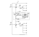
- FIG. 1 is a schematic diagram illustrating an arrangement state of a wiring junction box 1 according to the first embodiment in a vehicle.
- FIG. 2 is a block diagram illustrating a configuration of the wiring junction box 1. Inside the vehicle, a wiring branch box 1, a main power storage device 2, an auxiliary device 3, a load 5, a high-voltage power storage device 4, a communication device 6, an external communication device 7, and a sub power storage device 8 are provided.
- the main power storage device 2 is a 12V DC power supply such as a lead battery.
- Main power storage device 2 is connected to wiring branch box 1 by main power supply wiring 11.
- the auxiliary device 3 is, for example, a DCDC converter, which converts a DC high-voltage applied from a high-voltage power storage device 4 such as a lithium ion battery to 12 V and outputs it.
- the auxiliary equipment 3 and the main power storage device 2 are connected in parallel by a main power supply wiring 11, and the auxiliary equipment 3 is connected to the wiring branch box 1 by the main power supply wiring 11 similarly to the main power storage device 2.
- a load 5 such as a drive motor is connected to the main power storage device 2 and the auxiliary device 3 by a power supply line branched from the main power supply line 11, and the load 5 is supplied from the main power storage device 2 or the auxiliary device 3. It is driven by the electric power.
- the sub power storage device 8 is a 12 V DC power supply such as a lead battery.
- the sub power storage device 8 is connected to the wiring branch box 1 by a sub power supply wiring 12.
- the communication device 6 is communicably connected to a plurality of operation system main ECUs 20 (Electronic Control Unit), which will be described later, by a CAN (Controller Area Network / registered trademark) or Ethernet (registered trademark) cable, for example.
- the relay device relays communication between various ECUs including a plurality of operation system main ECUs 20, and is, for example, a relay device called a gateway.
- the wiring branch box 1 is communicably connected to the communication device 6 by a communication wiring 10 such as an Ethernet (registered trademark) cable. Further, the communication device 6 is communicably connected to the external communication device 7 by a harness such as a serial cable.
- a communication wiring 10 such as an Ethernet (registered trademark) cable.
- the communication device 6 is communicably connected to the external communication device 7 by a harness such as a serial cable.
- the external communication device 7 is connected to an antenna 71 for wireless communication with an external server (not shown) outside the vehicle by a harness or the like.
- the external communication device 7 performs wireless communication with an external server outside the vehicle using a predetermined wide area communication standard such as 5G, 4G or LTE, and is a communication device called TCU (Telematics Communication Unit), for example. .
- TCU Telematics Communication Unit
- the ECU includes an operation system ECU (operation system main ECU 20 and operation system sub ECU 25) for controlling traveling, stopping, steering and the like of the vehicle, and an automatic operation system ECU (judgment system main ECU 22) for controlling an automatic driving function of the vehicle.
- the recognition system main ECU 21 and the recognition system sub ECU 23 recognize a target such as an obstacle located outside the vehicle based on data acquired or detected by the various sensors 9 connected thereto.
- the judgment-system main ECU 22 and the judgment-system sub-ECU 24 make a judgment regarding driving of the vehicle based on the recognition result of the target.
- the operation-system main ECU 20 and the operation-system sub-ECU 25 control the operation of the actuator related to operations such as running, stopping, and steering of the vehicle based on the determination result.
- the automatic driving system ECU (the judgment system main ECU 22, the recognition system main ECU 21, the judgment system sub ECU 24, the cognition system sub ECU 23) and the operation system sub ECU 25 can communicate with the wiring branch box 1 by a communication cable 27 such as an Ethernet cable. It is connected. Although the details will be described later, the wiring branch box 1 is connected between the automatic driving system ECU (the judgment system main ECU 22, the recognition system main ECU 21, the judgment system sub ECU 24, the recognition system sub ECU 23), the operation system sub ECU 25, and the communication device 6. It functions as a repeater for relaying the communication in.
- the communication device 6 is connected to the external communication device 7, and the automatic driving system ECU (the judgment system main ECU 22, the recognition system main ECU 21, the judgment system sub ECU 24, the cognition system sub ECU 23) and the operation system sub ECU 25 are connected to the wiring branch box 1. It communicates with an external server (not shown) located outside the vehicle via the communication device 6 and the external communication device 7.
- the automatic driving system ECU the judgment system main ECU 22, the recognition system main ECU 21, the judgment system sub ECU 24, the cognition system sub ECU 23
- the operation system sub ECU 25 are connected to the wiring branch box 1. It communicates with an external server (not shown) located outside the vehicle via the communication device 6 and the external communication device 7.
- the power supplied through the main power supply wiring 11 or the sub power supply wiring 12 is supplied to the automatic driving system ECU (the judgment system main ECU 22, the recognition system main ECU 21, the judgment system sub ECU 24, the recognition system sub ECU 23) and the operation system sub ECU 25.
- the wiring branch box 1 is connected to the automatic driving system ECU (the judgment system main ECU 22, the recognition system main ECU 21, the judgment system sub ECU 24, the recognition system sub ECU 23) and the operation system sub ECU 25 by a communication cable 27.
- a power cable 26 as shown in FIG.
- the sensor 9 is communicably connected to the cognitive system main ECU 21 or the cognitive system sub ECU 23 by a harness (not shown) such as a serial cable.
- the sensor 9 includes an imaging unit such as a COMS camera that captures a scene outside the vehicle, an infrared sensor that detects a target located outside the vehicle, a millimeter wave radar, or a LiDAR (Light Detection and Ranging).
- the sensors are provided all around the vehicle, including the front, side and rear. There are two sensors 9 provided at each position, and these two sensors 9 have similar functions. Of the two sensors 9, one sensor 9 is connected to the cognitive main ECU 21, and the other sensor 9 is connected to the cognitive sub ECU 23.
- the present invention is not limited to the case where the sensors 9 have exactly the same function or the same specifications.
- one sensor 9 may be a COMS camera, and the other sensor 9 may be LiDAR.
- the obstacles located outside the vehicle are detected by the cognitive main ECU 21 or the cognitive sub ECU 23 connected to each of the sensors 9 based on the data acquired or detected. It may recognize a target such as.
- the operation system main ECU 20 is connected to the main power storage device 2 and the auxiliary device 3 by a power supply line branched from the main power supply line 11 similarly to the load 5, and is operated by the power supplied from the main power storage device 2 or the auxiliary device 3. Drive.
- the operation system main ECU 20 is communicably connected to the communication device 6 by, for example, an Ethernet cable.
- the plurality of operation system main ECUs 20 connected to the communication device 6 communicate with another ECU via the communication device 6 or an external server outside the vehicle via the communication device 6 and the external communication device 7.
- the vehicle configured as described above shows an aspect in which an automatic driving function is additionally mounted on a manually driven vehicle. That is, the vehicle was initially configured as a manually driven vehicle, and was equipped with an operation system main ECU 20 that controls the traveling, stopping, steering, and the like of the manually driven vehicle.
- the automatic driving ECUs (the main ECU 22 for the judgment system, the main ECU 21 for the recognition system, the sub ECU 24 for the judgment system, and the sub ECU 23 for the cognition system) and the automatic driving system ECUs
- various sensors 9 connected to the cognitive system main ECU 21 or the cognitive system sub ECU 23 are additionally mounted.
- the automatic driving system ECU includes a main ECU (a cognitive system main ECU 21 and a judgment system main ECU 22) and a sub ECU (a cognitive system sub ECU 23, a judgment system sub ECU 24).
- the sub power storage device 8 is additionally mounted on the power supply in addition to the redundancy by making it redundant.
- an operation system sub-ECU 25 is additionally mounted in order to make the operation system main ECU 20 mounted in the initially manually operated vehicle redundant.
- the automatic driving ECU and the operation ECU are duplicated, and a power supply source (the main power storage device 2 and the power storage device 2) to the automatic driving ECU and the operation ECU is used.
- a power supply source the main power storage device 2 and the power storage device 2 to the automatic driving ECU and the operation ECU is used.
- the wiring branch box 1 includes a main power input terminal 101, a main power line 102, a plurality of main power output terminals 104, a sub power input terminal 111, a sub power line 112, a plurality of sub power output terminals 114, a connection line 120, and a cutoff unit 121. including.
- the main power input terminal 101 is a power terminal or a socket to which the main power wiring 11 is connected.
- a main power line 102 is connected to the main power input terminal 101.
- the main power line 102 is composed of, for example, a cable or a bus bar. A current flowing from the main power storage device 2 or the auxiliary device 3 connected via the main power supply wiring 11 flows through the main power input terminal 101 to the main power line 102.
- the main power output terminal 104 is a power terminal or socket to which the power cable 26 that supplies power to the main ECU (the cognitive main ECU 21 and the judgment main ECU 22) is connected.
- the main power line 102 is formed of a cable or a bus bar, and is branched at the main power branch point 103 according to the number of the corresponding plurality of main power output terminals 104. Accordingly, the main power line 102 is branched at a main power branch point 103, and each of the branched main power lines 102 is connected to a corresponding main power output terminal 104.
- a fuse 130 is provided between the main power branch point 103 and each of the plurality of main power output terminals 104.
- a rated value such as a fusing characteristic is set according to a diameter size or an allowable current value of each of the branched main power lines 102.
- the sub power input terminal 111 is a power terminal or a socket to which the sub power wiring 12 is connected.
- a sub power line 112 is connected to the sub power input terminal 111.
- the sub power line 112 is configured by, for example, a cable or a bus bar. The current flowing from sub power storage device 8 connected via sub power supply wiring 12 flows to sub power line 112 via sub power input terminal 111.
- the sub power output terminal 114 is a power terminal or socket to which a power cable 26 for supplying power to the sub ECUs (the cognitive sub ECU 23, the determination sub ECU 24, and the operation sub ECU 25) is connected.
- the sub power line 112 is formed of a cable or a bus bar, and is branched at the sub power branch point 113 according to the number of the corresponding plurality of sub power output terminals 114. Accordingly, the sub power line 112 is branched at the sub power branch point 113, and each of the branched sub power lines 112 is connected to the corresponding sub power output terminal 114.
- a fuse 130 is provided between the sub power branch point 113 and each of the plurality of sub power output terminals 114.
- a rated value such as a fusing characteristic is set according to a diameter size or an allowable current value of each of the branched sub power lines 112.
- the wiring branch box 1 includes a main power system including a main power input terminal 101, a main power line 102, and a plurality of main power output terminals 104, and a sub power system including a sub power input terminal 111, a sub power line 112, and a plurality of sub power output terminals 114. And two power systems.
- a different power supply source main power storage device 2 and auxiliary device 3 or sub power storage device 8) is connected to each of the two power systems. That is, the main power storage system 2 and the auxiliary machine 3 are connected to the main power system.
- a sub power storage device 8 is connected to the sub power system. Therefore, even if one of the power supply sources fails, power can be continuously supplied to the ECU of the power system to which the other power supply source is connected.
- the main power input terminal 101 and the sub power input terminal 111 are electrically connected by a connection line 120.
- the connection line 120 is configured by a cable or a bus bar, like the main power line 102 and the sub power line 112.
- the main power input terminal 101 and the sub power input terminal 111 are electrically connected by the connection line 120, the power supplied from the main power storage device 2 or the auxiliary machine 3 via the main power supply wiring 11 and the sub power supply wiring 12 And the power supplied from the sub power storage device 8 via the main power line 102 or the sub power line 112 can be supplied to the main ECU and the sub ECU.
- the other power supply source supplies the main ECU and the sub ECU Power can be supplied to both.
- the power supplied from the sub power storage device 8 can be supplied to the main ECU via the connection line 120 and the main power line 102 (main power system).
- connection line 120 is provided with a cutoff unit 121 for cutting off the connection between the main power input terminal 101 and the sub power input terminal 111. Details will be described later.
- the wiring branch box 1 further includes a communication device-side communication port 140, a plurality of main ECU-side communication ports 153, a plurality of sub-ECU-side communication ports 163, a main communication branching unit 152, a sub communication branching unit 162, and a main communication branching unit 152. And a cascade unit 170 that connects the sub communication branch unit 162 with the sub communication branch unit 162.
- the communication device-side communication port 140 is a communication port having a connector shape corresponding to the Ethernet standard such as 100BASE-T1 or 1000BASE-T1, and functions as an input / output interface in communication by Ethernet.
- the wiring junction box 1 is connected to the communication device 6 via the communication device side communication port 140 by the communication wire 10 using, for example, an Ethernet cable.
- the communication port 153 on the main ECU side is a communication port having a connector shape corresponding to the Ethernet standard such as 100BASE-T1 or 1000BASE-T1, for example, like the communication port 140 on the communication device side. Function.
- the wiring branch box 1 is connected to the main ECU (the main ECU 21 for the recognition system and the main ECU 22 for the judgment system) via the main ECU communication port 153 by a communication cable 27 such as an Ethernet cable.
- the main communication branching unit 152 is connected to the communication device side communication port 140 via the main communication line 151.
- the main communication branching section 152 branches the main communication line 151 connected to the communication device side communication port 140 in accordance with the number of the plurality of main ECU side communication ports 153. That is, each of the main communication lines 151 branched by the main communication branching unit 152 is connected to a corresponding one of the plurality of main ECU-side communication ports 153. In this way, the main communication branching unit 152 forms a branch circuit that branches the communication wiring 10 connected to the communication device-side communication port 140.
- the main communication branching unit 152 may be configured by, for example, a layer 2 switch or a layer 3 switch Ethernet switch.
- the Ethernet switch is provided by the communication device-side communication port 140, the plurality of main ECU-side communication ports 153, the main communication branching unit 152, and the main communication line 151 connecting each main ECU-side communication port 153 and the main communication branching unit 152. May be constituted.
- the main communication branching unit 152 corresponds to a microcomputer that controls the Ethernet switch
- the main communication line 151 corresponds to an internal bus provided in the Ethernet switch.
- the main communication branching unit 152 may detect, for example, a communication abnormality in each of the main ECU communication ports 153 and shut off the main ECU communication port 153 that has detected the abnormality. Even if the main ECU communication port 153 is shut off, the sub ECU having the same function as that of the main ECU connected to the main ECU communication port 153 performs functions necessary for running the vehicle. Can be.
- the sub-ECU-side communication port 163 is a connector-shaped communication port compliant with the Ethernet standard such as 100BASE-T1 or 1000BASE-T1, for example, like the main ECU-side communication port 153, and serves as an input / output interface in Ethernet communication. Function.
- the wiring branch box 1 is connected to the sub-ECUs (the cognitive sub-ECU 23, the judgment sub-ECU 24, and the operation sub-ECU 25) via the sub-ECU-side communication port 163 via a communication cable 27 such as an Ethernet cable.
- the sub-communication branching unit 162 and the main communication branching unit 152 are connected by the cascade unit 170.
- the cascade unit 170 is configured by, for example, a cascade port included in the sub communication branch unit 162.
- the cascade unit 170 and the main communication branch unit 152 are connected by a main communication line 151, and the cascade unit 170 and the sub communication branch unit 162 are connected by a sub communication line 161, so that the sub communication branch unit 162 and the main communication line are connected.
- the branch part 152 is connected.
- the sub communication branch unit 162 is connected to the communication device side communication port 140 via the sub communication line 161, the cascade unit 170, and the main communication branch unit 152.
- the sub-communication branching unit 162 branches the sub-communication line 161 according to the number of the plurality of sub-ECU-side communication ports 163. That is, each of the sub communication lines 161 branched by the sub communication branch unit 162 is connected to a corresponding one of the plurality of sub ECU side communication ports 163. As described above, the sub-communication branching unit 162 forms a branch circuit that branches the communication wiring 10 connected to the communication device-side communication port 140.
- the sub-communication branching unit 162 may be composed of, for example, a layer 2 switch or a layer 3 switch Ethernet switch.
- the Ethernet switch is configured by the cascade unit 170, the plurality of sub-ECU-side communication ports 163, the sub-communication branching unit 162, and the sub-communication line 161 connecting each sub-ECU-side communication port 163 and the sub-communication branch unit 162. It may be something.
- the sub-communication branching unit 162 corresponds to a microcomputer that controls the Ethernet switch
- the sub-communication line 161 corresponds to an internal bus provided in the Ethernet switch.
- the sub-communication branching unit 162 may detect, for example, a communication abnormality in each sub-ECU communication port 163 and shut off the sub-ECU communication port 163 that has detected the abnormality. Even when the sub-ECU communication port 163 is shut off, the main ECU having the same function as the sub-ECU connected to the sub-ECU communication port 163 performs functions necessary for running the vehicle. Can be.
- the wiring branch box 1 has two communication systems: a main communication system including a main communication branch unit 152 and a plurality of main ECU communication ports 153, and a sub communication system including a sub communication branch unit 162 and a plurality of sub ECU communication ports 163. Is provided.
- the main ECU is connected to the main communication system
- the sub ECU is connected to the sub communication system.
- the main ECU and each of the sub-ECUs having the same function corresponding to each of the main ECUs are communicably connected to the wiring branch box 1, and are duplicated and redundant by the main ECU of the main communication system and the sub-ECU of the sub communication system. Can be achieved. Therefore, even if a communication error occurs in one of the main communication system and the sub communication system, automatic operation is performed by the ECU (main ECU or sub ECU) connected to the other communication system. Function can be continued.
- the main ECU (the cognitive main ECU 21 and the judgment main ECU 22) is connected to the main ECU side communication port 153 and the main power output terminal 104. That is, the main ECU side communication port 153 and the main ECU are connected by the communication cable 27, and the main ECU communicates with another ECU via the wiring branch box 1.
- the wiring junction box 1 relays communication between these ECUs.
- the main power output terminal 104 and the main ECU are connected by a power cable 26, and power is supplied (distributed) to the main ECU via the wiring branch box 1.
- a sub ECU (a cognitive sub ECU 23, a judgment sub ECU 24, and an operation sub ECU 25) is connected to the sub ECU communication port 163 and the sub power output terminal 114. That is, the communication port 163 on the sub-ECU side and the sub-ECU are connected by the communication cable 27, and the sub-ECU communicates with another ECU via the wiring branch box 1.
- the wiring junction box 1 relays communication between these ECUs.
- the sub-power output terminal 114 and the sub-ECU are connected by the power cable 26, and power is supplied (distributed) to the sub-ECU via the wiring branch box 1.
- the wiring branch box 1 configured as described above, particularly when an automatic driving function is additionally mounted on a manually driven vehicle, a branch and a plan for duplicating and redundantly adding each ECU to be additionally mounted are provided.
- the power supply cable 26 and the communication cable 27 connected to each of the ECUs to be integrated and additionally mounted can be efficiently arranged.
- the power line (main power line 102, sub power line 112) and communication line (main communication line 151, sub communication line 161) are duplicated, that is, by providing a main system and a sub system in power and communication.
- the power line main power line 102, sub power line 112
- communication line main communication line 151, sub communication line 161
- redundancy in power supply and security of communication can be achieved, and the fault tolerance or availability of the automatic driving function can be improved.
- FIG. 2 and FIG. 4 to be described later in the main system, only one system located on the upper side on the paper is denoted by a reference numeral, and the other system is omitted.
- the sub-system only one system located on the upper side on the paper is denoted by a reference numeral, and the others are omitted.
- the main ECU side communication port 153 and main power output terminal 104 corresponding to each main ECU may be configured as a composite connector in which these are integrated. That is, the wiring branch box 1 includes a composite connector (hybrid connector) in which a plurality of power terminals or communication terminals of the main ECU side communication port 153 and the main power output terminal 104 are combined and mixed in one connector. It may be. Similarly, the sub-ECU-side communication port 163 and the sub-power output terminal 114 corresponding to each sub-ECU may be configured as a composite connector (hybrid connector) in which these are integrated.
- the automatic driving function is additionally mounted by configuring the communication port 153 and the main power output terminal 104 on the main ECU side or the communication port 163 and the sub power output terminal 114 on the sub ECU side as a composite connector (composite main connector, composite sub connector). In doing so, the additional mounting of the main ECU and the sub-ECU can be easily performed, and the man-hour required for additionally mounting the automatic driving function can be reduced.
- FIG. 3 is a block diagram showing the configuration of the shutoff unit 121 (separation unit).
- the shutoff unit 121 includes a relay 124, an abnormality detection unit 122, and a control unit 123.
- the disconnection unit 121 When detecting an abnormality in the connection line 120, the disconnection unit 121 disconnects the connection line 120, that is, disconnects and disconnects the main power input terminal 101 and the sub power input terminal 111 connected by the connection line 120. Part.
- the relay 124 is provided on the connection line 120 and is, for example, a b-contact relay that is always on.
- the abnormality detection unit 122 includes a current sensor including a Hall element or the like that detects a current value flowing through the connection line 120, a voltage sensor including a shunt resistor or the like that detects a grounding voltage of the connection line 120, or a temperature of the connection line 120 (joule). It includes a temperature sensor such as a thermistor for detecting heat, and detects the amount of electrical state in the connection line 120.
- the abnormality detection unit 122 has sensors of the abnormality detection unit 122 disposed at both ends of the relay 124 so as to detect the amount of electrical state at both ends of the relay 124. By arranging the sensors in this manner, the potential difference between both ends of the relay 124 can be detected.
- the relay 124 After the relay 124 is turned off by detecting the amount of electrical state at both ends of the relay 124, the amount of electrical state at the main power input terminal 101 and the amount of electrical state at the auxiliary power input terminal 111 are determined. Both electrical state quantities can be obtained. Note that the abnormality detection unit 122 may detect an electrical state quantity on one side of the relay 124.
- the control unit 123 is configured by a microcomputer including an MPU (microprocessor unit) and a memory.
- the control unit 123 determines the presence or absence of an abnormality in the connection line 120 based on the detection value detected by the abnormality detection unit 122, and turns off the relay 124 when it is determined that there is an abnormality (abnormality has occurred).
- the voltage output from the main power storage device 2 or the auxiliary machine 3 is applied to the main power input terminal 101.
- the voltage output from sub power storage device 8 is applied to sub power input terminal 111.
- a current flows through the connection line 120 connecting the main power input terminal 101 and the sub power input terminal 111 according to the potential difference between the main power input terminal 101 and the sub power input terminal 111. For example, when a ground fault occurs in the main power line 102, the potential of the main power input terminal 101 becomes 0 V (a ground reference potential), so that the sub power input terminal 111 is also connected to the main power line 102 via the connection line 120. A large current flows.
- the control unit 123 determines that when a large current of a predetermined value or more flows through the connection line 120, the temperature of the connection line 120 exceeds a predetermined temperature due to Joule heat generated by the large current.
- a predetermined value such as approximately 0 V
- the relay 124 is turned off.
- the main power input terminal 101 and the sub power input terminal 111 are disconnected. That is, the main power system and the sub power system are separated.
- power is supplied to an ECU (main ECU or sub ECU) connected to a normal power system.
- the cutoff unit 121 By providing the cutoff unit 121 in this manner, even if an abnormality occurs in the main power line 102 or the sub power line 112, the fuse of the main power storage device 2 or the sub power storage device 8 connected to the side where the abnormality has occurred can be changed.
- the main power input terminal 101 and the sub power input terminal 111 can be separated faster than melting.
- the relay 124 is a mechanical relay using a b-contact relay, but is not limited to this.
- the relay 124 may be a semiconductor relay such as an FET or an IGBT.
- the wiring branch box 1 is disposed between the main power storage device 2 and the sub power storage device 8, and is provided so as to be located at a central portion in front and rear of the vehicle.
- the main power storage device 2 is disposed at the front of the vehicle, and the sub power storage device 8 additionally mounted when the automatic driving function is additionally mounted is disposed at the rear of the vehicle.
- the wiring branch box 1 By arranging the wiring branch box 1 between the main power storage device 2 at the front of the vehicle and the sub power storage device 8 at the rear, the wiring branch box 1 is located at the center in the front and rear of the vehicle.
- the wiring branch box 1 may be provided as a central portion of the vehicle, for example, in a console in a vehicle compartment, in an instrument panel, or below a seat.
- Various sensors 9 such as a cognitive sensor, which are additionally mounted in addition to the automatic driving function, automatic driving ECUs (cognitive main ECU 21, judgment main ECU 22, cognitive sub ECU 23, judgment sub ECU 24) and operation
- the system sub-ECU 25 is appropriately disposed inside the vehicle based on the use or function.
- providing the wiring branch box 1 in the center of the vehicle contributes to equalizing the distance from each of the additionally mounted various sensors 9 and the ECU (automatic driving system ECU, operation system sub ECU 25). be able to. Therefore, it is possible to efficiently carry out the distribution such as shortening the cable length of the power supply cable 26 and the communication cable 27 between the additionally mounted various sensors 9 and the ECU and the wiring branch box 1.
- the wiring branch box 1 is additionally equipped with an automatic driving system ECU (evaluation system main ECU 22, cognition system main ECU 21, judgment system sub ECU 24, recognition system sub ECU 23) and operation.
- the power supply wiring (main power supply wiring 11, sub-power supply wiring 12) and communication wiring 10 to be arranged are integrated for the system sub-ECU 25.
- the power supply wiring (main power supply wiring 11 and sub-power supply wiring 12) and the communication wiring 10 are concentrated in the wiring branch box 1 and branched, so that the power supply wiring (main power supply wiring 11 and sub-power supply wiring 12) and the communication wiring 10 are connected. It is possible to simplify the allocation and reduce the man-hours required for additionally implementing the automatic driving function.
- the wiring branch box 1 compared with the case where the power supply wiring and the communication wiring 10 are separately aggregated and branched, the number of connection points of these wirings (harness) can be reduced, the number of units can be reduced, and the number of parts can be reduced. Reduction, cost reduction, or shortening of a work process in a vehicle can be achieved.
- the wiring branch box 1 includes a main system and a sub-system in electric power and communication so as to correspond to a main ECU and a sub-ECU for redundancy and redundancy when additionally mounting an automatic driving function on a manually driven vehicle. Prepare. By making the power supply and communication redundant by these main system and sub-system, it is possible to reduce the man-hour for additional mounting of the automatic driving function, to contribute to the improvement of the availability of the automatic driving function and to guarantee the reliability. .
- the cutoff unit 121 By providing the cutoff unit 121, even if an abnormality such as a ground fault occurs in any of the power systems, the connection between the main power input terminal 101 and the sub power input terminal 111 is interrupted, and an abnormality occurs.
- the power supply to the ECU (main ECU or sub ECU) connected to the power system that is not connected can be continued.
- the vehicle is shown as an embodiment in which an automatic driving function is additionally mounted on a manually driven vehicle, but the present invention is not limited to this.
- Vehicles include those manufactured as self-driving vehicles.
- the wiring junction box 1 can be applied to a vehicle having an automatic driving function from the beginning of the manufacturing stage.
- the operation system main ECU 20 has the same power and communication system as the main ECUs (the cognition system main ECU 21 and the judgment system main ECU 22). It may be connected to the main system.
- the automatic driving system ECU (the judgment system main ECU 22, the recognition system main ECU 21, the judgment system sub ECU 24, the recognition system sub ECU 23) and the operation system ECU (the operation system main ECU 20, the operation system sub ECU 25).
- FIG. 4 is a block diagram illustrating the configuration of the wiring junction box 1 according to the second embodiment (the communication port on the communication device side is made redundant).
- the wiring branch box 1 according to the second embodiment differs from the first embodiment in that the communication device-side communication port 140 connected to the communication device 6 includes two communication ports, a main communication port 141 and a sub communication port 142.
- the wiring junction box 1 includes a main communication port 141 and a sub communication port 142. Like the communication device-side communication port 140 of the first embodiment, the main communication port 141 and the sub communication port 142 are connector-shaped communication ports conforming to the Ethernet standard such as 100BASE-T1 or 1000BASE-T1, for example. Function as an input / output interface in communication by the The wiring branch box 1 is connected to the communication device 6 via the main communication port 141 and the sub communication port 142 by the communication wiring 10 using an Ethernet cable.
- the main communication branching unit 152 is connected to the main communication port 141 by the main communication line 151.
- the sub-communication branching unit 162 is connected to the sub-communication port 142 by a sub-communication line 161. That is, the main communication branching unit 152 and the sub communication branching unit 162 are connected in parallel to the communication device 6.
- connection between the main communication branching unit 152 and the plurality of main ECU-side communication ports 153 is the same as in the first embodiment.
- connection between the sub communication branching section 162 and the plurality of sub ECU side communication ports 163 is the same as in the first embodiment.
- the cascade unit 170 that connects the main communication branch unit 152 and the sub communication branch unit 162 can be omitted.
- the main communication system formed by the main communication branching unit 152 and the plurality of main ECU communication ports 153 and the sub communication system formed by the sub communication branching unit 162 and the plurality of sub ECU communication ports 163 are connected to the communication device 6 at the connection level. And can be completely separated. Therefore, the communication between the wiring junction box 1 and the communication device 6 can be duplicated for redundancy. That is, even when the main communication branching unit 152 fails and communication becomes impossible, the sub ECU can communicate with the communication device 6 via the sub communication branching unit 162. It is possible to communicate with an external server outside the vehicle via the external communication device 7.
- the communication between the wiring branch box 1 and the communication device 6 is also duplicated and made redundant, so that even if an abnormality occurs in the main communication system or the sub communication system, the connection to a communication system in which no abnormality has occurred is established. Communication between the selected automatic driving ECU (main ECU or sub ECU) and an external server outside the vehicle is ensured, and the automatic driving function can be reliably continued.
- the cascade unit 170 for connecting the main communication branch unit 152 and the sub communication branch unit 162 is not required, the present invention is not limited to this.
- the main communication branching unit 152 and the sub communication branching unit 162 may be connected by the cascade unit 170 as in the first embodiment.
- the main ECU connected to the main communication branching unit 152 and the sub communication branching unit 162 are connected without passing through the communication device 6.
- the communication with the sub-ECU can be relayed in the wiring junction box 1.
Abstract
This wiring junction box is a wiring junction box that branches wires connected to a plurality of ECUs mounted on a vehicle, and comprises: a power input terminal connected to a power storage device that supplies power to the ECUs; a plurality of power output terminals which output power input from the power input terminal to each of the plurality of ECUs; a communication device-side communication port connected to a communication device that communicates with the ECU; and a plurality of ECU-side communication ports which are respectively connected to the plurality of ECUs, wherein the wires include a power line connecting the power input terminal and the power output terminal, and a communication line connecting the communication device-side communication port and the ECU-side communication port, the power line is branched according to the number of the plurality of power output terminals, and the communication line is branched according to the number of the plurality of ECU-side communication ports.
Description
本開示は、配線分岐箱に関する。
本出願は、2018年9月10日出願の日本出願第2018-169086号に基づく優先権を主張し、前記日本出願に記載された全ての記載内容を援用するものである。 The present disclosure relates to a wiring junction box.
This application claims the priority based on Japanese Patent Application No. 2018-169086 filed on Sep. 10, 2018, and incorporates all the contents described in the Japanese application.
車両には、蓄電装置等の車両用電源が搭載されており、当該車両用電源からの電力線を分岐し、分岐した電力線を介してECU(Electronic Control Unit)等の車載機器(負荷)に電力を分配して供給する車両用電気接続箱が知られている(例えば特許文献1)。
The vehicle is equipped with a vehicle power supply such as a power storage device, branches a power line from the vehicle power supply, and supplies power to a vehicle-mounted device (load) such as an ECU (Electronic Control Unit) via the branched power line. 2. Description of the Related Art An electric connection box for a vehicle that is distributed and supplied is known (for example, Patent Document 1).
特許文献1の車両用電気接続箱は、車両用電源に接続される電源端子、当該電源端子に接続されたリレー及び、当該リレーの後段側に位置し、4系統に分岐された電線を備えている。4系統に分岐された電線夫々には、負荷が接続されており、これら4つの負荷夫々には、車両用電源からの電力が分配されて供給される。
The electric connection box for a vehicle of Patent Literature 1 includes a power supply terminal connected to a power supply for a vehicle, a relay connected to the power supply terminal, and an electric wire located at a rear stage of the relay and branched into four systems. I have. A load is connected to each of the four branched wires, and power from a vehicle power supply is distributed and supplied to each of these four loads.
本開示の一態様に係る配線分岐箱は、車両に搭載される複数のECUに接続する配線を分岐する配線分岐箱であって、前記ECUに電力を供給する蓄電装置に接続される電力入力端子と、前記電力入力端子から入力された電力を前記複数のECU夫々に出力する複数の電力出力端子と、前記ECUと通信する通信装置に接続される通信装置側通信ポートと、前記複数のECU夫々に接続される複数のECU側通信ポートとを備え、前記配線は、前記電力入力端子と前記電力出力端子とを接続する電力線及び、前記通信装置側通信ポートと前記ECU側通信ポートとを接続する通信線を含み、前記電力線は、前記複数の電力出力端子の個数に応じて分岐され、前記通信線は、前記複数のECU側通信ポートの個数に応じて分岐されている。
A wiring branch box according to an aspect of the present disclosure is a wiring branch box that branches wiring connected to a plurality of ECUs mounted on a vehicle, and a power input terminal connected to a power storage device that supplies power to the ECU. A plurality of power output terminals for outputting power input from the power input terminal to each of the plurality of ECUs; a communication device-side communication port connected to a communication device communicating with the ECU; A plurality of ECU-side communication ports connected to the power supply line, and the wiring connects a power line connecting the power input terminal and the power output terminal, and connects the communication device-side communication port and the ECU-side communication port. A communication line is included, the power line is branched according to the number of the plurality of power output terminals, and the communication line is branched according to the number of the plurality of ECU-side communication ports.
[本開示が解決しようとする課題]
ECUを機能させるためには当該ECUに電力を供給する共に、これらECU間での通信を行うための通信線をECU夫々に接続する必要があるが、特許文献1の配線分岐箱は、電力線のみを分岐するものであるため、これらECU夫々に接続する通信線の分岐等の配策ができないという問題点がある。 [Problems to be solved by the present disclosure]
In order for the ECUs to function, it is necessary to supply power to the ECUs and connect a communication line for performing communication between the ECUs to each of the ECUs. Therefore, there is a problem that it is not possible to provide a measure such as a branch of a communication line connected to each of the ECUs.
本開示は斯かる事情に鑑みてなされたものであり、電力線及び通信線の分岐等の配策に対応した配線分岐箱を提供することを目的とする。
The present disclosure has been made in view of such circumstances, and has as its object to provide a wiring branch box corresponding to a measure such as branching of a power line and a communication line.
[本開示の効果]
本開示の一態様によれば、電力線及び通信線の分岐等の配策に対応した配線分岐箱を提供することができる。 [Effects of the present disclosure]
According to an aspect of the present disclosure, it is possible to provide a wiring branch box that supports a measure such as branching of a power line and a communication line.
本開示の一態様によれば、電力線及び通信線の分岐等の配策に対応した配線分岐箱を提供することができる。 [Effects of the present disclosure]
According to an aspect of the present disclosure, it is possible to provide a wiring branch box that supports a measure such as branching of a power line and a communication line.
[本開示の実施形態の説明]
最初に本開示の実施態様を列挙して説明する。また、以下に記載する実施形態の少なくとも一部を任意に組み合わせてもよい。 [Description of Embodiment of the Present Disclosure]
First, embodiments of the present disclosure will be listed and described. Further, at least some of the embodiments described below may be arbitrarily combined.
最初に本開示の実施態様を列挙して説明する。また、以下に記載する実施形態の少なくとも一部を任意に組み合わせてもよい。 [Description of Embodiment of the Present Disclosure]
First, embodiments of the present disclosure will be listed and described. Further, at least some of the embodiments described below may be arbitrarily combined.
(1)本開示の一態様に係る配線分岐箱は、車両に搭載される複数のECUに接続する配線を分岐する配線分岐箱であって、前記ECUに電力を供給する蓄電装置に接続される電力入力端子と、前記電力入力端子から入力された電力を前記複数のECU夫々に出力する複数の電力出力端子と、前記ECUと通信する通信装置に接続される通信装置側通信ポートと、前記複数のECU夫々に接続される複数のECU側通信ポートとを備え、前記配線は、前記電力入力端子と前記電力出力端子とを接続する電力線及び、前記通信装置側通信ポートと前記ECU側通信ポートとを接続する通信線を含み、前記電力線は、前記複数の電力出力端子の個数に応じて分岐され、前記通信線は、前記複数のECU側通信ポートの個数に応じて分岐されている。
(1) A wiring branch box according to an aspect of the present disclosure is a wiring branch box that branches wiring connected to a plurality of ECUs mounted on a vehicle, and is connected to a power storage device that supplies power to the ECU. A power input terminal, a plurality of power output terminals for outputting power input from the power input terminal to each of the plurality of ECUs, a communication device-side communication port connected to a communication device communicating with the ECU; A plurality of ECU-side communication ports connected to each of the ECUs, wherein the wiring includes a power line connecting the power input terminal and the power output terminal, and the communication device-side communication port and the ECU-side communication port. The power line is branched according to the number of the plurality of power output terminals, and the communication line is branched according to the number of the plurality of ECU communication ports.
本態様にあたっては、配線分岐箱は、複数のECUに接続する電力線及び通信線を分岐し配策するようにしてあるため、当該複数のECUに対する電力線及び通信線の配策の対応を簡易化することができ、車両内における配策性を向上させることができる。
In this aspect, since the wiring branch box branches and arranges the power line and the communication line connected to the plurality of ECUs, it simplifies the correspondence of the arrangement of the power line and the communication line to the plurality of ECUs. And the arrangability in the vehicle can be improved.
(2)本開示の一態様に係る配線分岐箱は、前記複数のECUは、複数の自動運転系ECUを含み、前記複数の自動運転系ECUは、主ECU及び副ECUを含み、前記電力線及び前記通信線夫々は、前記主ECU及び前記副ECU夫々に対応した系統を有する。
(2) In the wiring junction box according to an aspect of the present disclosure, the plurality of ECUs include a plurality of automatic driving ECUs, the plurality of automatic driving ECUs include a main ECU and a sub ECU, and the power lines and Each of the communication lines has a system corresponding to each of the main ECU and the sub ECU.
本態様にあたっては、車両に自動運転機能を実装するにあたり、自動運転機能に必要な複数の自動運転系ECUを追加搭載する必要があり、当該自動運転系ECUは、可用性の向上又は信頼性の担保の見地より冗長化されることが望ましい。これに対し、配線分岐箱は、主ECU及び副ECU夫々に対応した系統を有する電力線及び通信線を含むことにより主ECU及び副ECUを冗長化する。冗長化された主ECU及び副ECU夫々に対応して、これら電力線及び通信線の配策を簡易化しつつ、自動運転機能の信頼性担保等に寄与することができる。なお、車両への自動運転機能の実装は、当初手動運転の車両に自動運転機能を追加実装することを含む。
In this aspect, in order to implement the automatic driving function in the vehicle, it is necessary to additionally install a plurality of automatic driving ECUs required for the automatic driving function, and the automatic driving ECU may improve availability or ensure reliability. It is desirable to make the redundancy redundant from the viewpoint of the above. On the other hand, the wiring branch box makes the main ECU and the sub ECU redundant by including a power line and a communication line having systems corresponding to the main ECU and the sub ECU, respectively. Corresponding to the redundant main ECU and sub-ECU, respectively, it is possible to simplify the layout of these power lines and communication lines and contribute to ensuring the reliability of the automatic driving function. Note that the implementation of the automatic driving function on the vehicle includes additionally mounting the automatic driving function on the vehicle that is initially manually driven.
(3)本開示の一態様に係る配線分岐箱は、前記電力線は、前記主ECUに対応した系統の主電力線と、前記副ECUに対応した系統の副電力線とを含み、前記通信線は、前記主ECUに対応した系統の主通信線と、前記副ECUに対応した系統の副通信線とを含み、前記主電力線は、前記主ECU用の電力出力端子の個数に応じて分岐され、前記主通信線は、前記主ECU用のECU側通信ポートの個数に応じて分岐され、前記副電力線は、前記副ECU用の電力出力端子の個数に応じて分岐され、前記副通信線は、前記副ECU用のECU側通信ポートの個数に応じて分岐されている。
(3) In the wiring branch box according to an aspect of the present disclosure, the power line includes a main power line of a system corresponding to the main ECU and a sub power line of a system corresponding to the sub ECU, and the communication line includes: A main communication line of a system corresponding to the main ECU; and a sub communication line of a system corresponding to the sub ECU.The main power line is branched according to the number of power output terminals for the main ECU. The main communication line is branched according to the number of ECU-side communication ports for the main ECU, the sub power line is branched according to the number of power output terminals for the sub ECU, and the sub communication line is The branch is made according to the number of ECU-side communication ports for the sub ECU.
本態様にあたっては、主電力線及び主通信線は、接続される主ECU用の電力出力端子及びECU側通信ポートの個数に応じて分岐され、副電力線及び副通信線は、接続される副ECU用の電力出力端子及びECU側通信ポートの個数に応じて分岐されるため、系統夫々における分岐数の適正化を図ることができる。
In this aspect, the main power line and the main communication line are branched according to the number of power output terminals for the main ECU and the number of ECU-side communication ports to be connected, and the sub power line and the sub communication line are connected to the sub ECU for the sub ECU. The number of branches is determined according to the number of power output terminals and ECU-side communication ports, so that the number of branches in each system can be optimized.
(4)本開示の一態様に係る配線分岐箱は、副蓄電装置に接続される副電力入力端子を備え、前記電力線は、前記電力入力端子と前記副電力入力端子との間を接続する接続線を含み、前記接続線によって、前記主ECU及び前記副ECUへの電力の供給を冗長化する。
(4) The wiring junction box according to an aspect of the present disclosure includes a sub power input terminal connected to a sub power storage device, and the power line connects between the power input terminal and the sub power input terminal. And the connection lines make power supply to the main ECU and the sub-ECU redundant.
本態様にあたっては、接続線は電力入力端子と副電力入力端子との間を接続するため、電力入力端子又は副電力入力端子を介して蓄電装置及び副蓄電装置夫々から入力された電力を、主ECU及び副ECUの双方に供給することができる。従って、蓄電装置又は副蓄電装置のいずれか一方が故障となった場合であっても、他方からの電力の供給を継続して冗長化を図ることができる。
In this aspect, since the connection line connects between the power input terminal and the sub power input terminal, the power input from the power storage device and the sub power storage device via the power input terminal or the sub power input terminal is mainly used. It can be supplied to both the ECU and the sub ECU. Therefore, even if one of the power storage device and the sub power storage device fails, power can be continuously supplied from the other device to achieve redundancy.
(5)本開示の一態様に係る配線分岐箱は、前記接続線には、前記電力入力端子と前記副電力入力端子とを切り離す切り離し部が設けられ、前記切り離し部は、前記接続線に異常が生じた場合、前記電力入力端子と前記副電力入力端子とを切り離す。
(5) In the wiring branch box according to an aspect of the present disclosure, the connection line is provided with a disconnection section that disconnects the power input terminal and the sub power input terminal, and the disconnection section has an abnormality in the connection line. Is generated, the power input terminal and the sub power input terminal are disconnected.
本態様にあたっては、主電力線又は副電力線に地絡等の異常が生じると、蓄電装置及び副蓄電装置から出力された電力は、主ECU及び副ECUに供給されないものとなるが、切り離し部が、接続線によって接続されている電力入力端子と副電力入力端子とを切り離す。電力入力端子と副電力入力端子とを切り離すことにより、地絡が発生していない電力線側の電力入力端子又は副電力入力端子から入力される電力を、主ECU又は副ECUに供給することを継続することができる。
In this aspect, when an abnormality such as a ground fault occurs in the main power line or the sub power line, the power output from the power storage device and the sub power storage device is not supplied to the main ECU and the sub ECU, but the disconnection unit is The power input terminal and the sub power input terminal connected by the connection line are disconnected. By separating the power input terminal and the sub power input terminal, the power input from the power input terminal or the sub power input terminal on the power line side where no ground fault has occurred continues to be supplied to the main ECU or the sub ECU. can do.
(6)本開示の一態様に係る配線分岐箱は、前記主通信線に接続され、前記主通信線を分岐する主通信分岐部と、前記副通信線に接続され、前記副通信線を分岐する副通信分岐部とを備え、前記主通信分岐部及び前記副通信分岐部は、レイヤー2スイッチ又はレイヤー3スイッチとして機能する。
(6) The wiring branch box according to an aspect of the present disclosure is connected to the main communication line and branches the main communication line, and is connected to the sub communication line to branch the sub communication line. The main communication branching unit and the sub communication branching unit function as a layer 2 switch or a layer 3 switch.
本態様にあたっては、主通信分岐部及び副通信分岐部をレイヤー2スイッチ又はレイヤー3スイッチとすることで、主通信分岐部及び副通信分岐部において、各レイヤーに応じた通信の中継処理を効率的に行うことができる。
In this aspect, the main communication branching unit and the sub-communication branching unit are configured as a layer 2 switch or a layer 3 switch, so that the main communication branching unit and the sub-communication branching unit can efficiently relay the communication according to each layer. Can be done.
(7)本開示の一態様に係る配線分岐箱は、前記通信装置側通信ポートは、主通信ポート及び副通信ポートを含み、前記主通信ポートには、前記主通信線が接続され前記副通信ポートには、前記副通信線が接続される。
(7) In the wiring branch box according to an aspect of the present disclosure, the communication device-side communication port includes a main communication port and a sub communication port, and the main communication line is connected to the main communication line to connect to the sub communication. The sub communication line is connected to the port.
本態様にあたっては、通信装置側通信ポートは主通信ポート及び副通信ポートを含み、主通信ポート及び副通信ポート夫々は、通信装置に接続されている。従って、配線分岐箱と通信装置との通信を二重化することにより冗長化を図ることができる。
In this aspect, the communication device side communication port includes a main communication port and a sub communication port, and each of the main communication port and the sub communication port is connected to the communication device. Therefore, redundancy can be achieved by duplicating communication between the wiring junction box and the communication device.
(8)本開示の一態様に係る配線分岐箱は、前記複数のECUは、操作系主ECU及び操作系副ECUを含み、前記操作系副ECUは、前記副ECUと同じ系統の前記電力線及び前記通信線に接続される。
(8) In the wiring branch box according to an aspect of the present disclosure, the plurality of ECUs include an operation system main ECU and an operation system sub ECU, and the operation system sub ECU is configured to include the power line and the same system as the sub ECU. It is connected to the communication line.
本態様にあたっては、操作系副ECUは、副ECUと同じ系統の前記電力線及び前記通信線に接続されるようにしてある。従って、例えば、自動運転機能を追加実装するにあたり、操作系副ECUを追加搭載して操作系ECUについても冗長化した場合であっても、当該操作系副ECUへの電力線及び通信線の対応を簡易化することができ、車両内における配策性を向上させることができる。
In this aspect, the operation system sub-ECU is connected to the power line and the communication line in the same system as the sub-ECU. Therefore, for example, when the automatic driving function is additionally mounted, even if the operation system sub-ECU is additionally mounted and the operation system ECU is also made redundant, the correspondence of the power line and the communication line to the operation system sub-ECU is required. Simplification can be achieved, and the arrangability in the vehicle can be improved.
(9)本開示の一態様に係る配線分岐箱は、前記蓄電装置及び前記副蓄電装置の間に配され、前記車両の中央部に位置するように設けられている。
(9) The wiring junction box according to an aspect of the present disclosure is arranged between the power storage device and the sub power storage device, and is provided so as to be located at a central portion of the vehicle.
本態様にあたっては、配線分岐箱を蓄電装置及び副蓄電装置の間に配し、車両の中央部に位置するように設けることにより、配線分岐箱と、蓄電装置及び副蓄電装置との間の電源配線の配策を簡素化すると共に、車両外部からの物理的な衝撃に対する耐性を向上させることができる。
According to this aspect, the wiring branch box is disposed between the power storage device and the sub power storage device, and is provided so as to be located at the center of the vehicle, so that the power supply between the wiring branch box and the power storage device and the sub power storage device is provided. The wiring arrangement can be simplified, and the resistance to physical impacts from outside the vehicle can be improved.
[本開示の実施形態の詳細]
本開示をその実施の形態を示す図面に基づいて具体的に説明する。本開示の実施形態に係る配線分岐箱1を、以下に図面を参照しつつ説明する。なお、本開示はこれらの例示に限定されるものではなく、請求の範囲によって示され、請求の範囲と均等の意味及び範囲内でのすべての変更が含まれることが意図される。 [Details of Embodiment of the Present Disclosure]
The present disclosure will be specifically described with reference to the drawings illustrating the embodiments. Awiring branch box 1 according to an embodiment of the present disclosure will be described below with reference to the drawings. Note that the present disclosure is not limited to these exemplifications, but is indicated by the scope of the claims, and is intended to include all modifications within the scope and meaning equivalent to the scope of the claims.
本開示をその実施の形態を示す図面に基づいて具体的に説明する。本開示の実施形態に係る配線分岐箱1を、以下に図面を参照しつつ説明する。なお、本開示はこれらの例示に限定されるものではなく、請求の範囲によって示され、請求の範囲と均等の意味及び範囲内でのすべての変更が含まれることが意図される。 [Details of Embodiment of the Present Disclosure]
The present disclosure will be specifically described with reference to the drawings illustrating the embodiments. A
(実施形態1)
図1は、実施形態1に係る配線分岐箱1の車両における配置状態を示す模式図である。図2は、配線分岐箱1の構成を示すブロック図である。車両の内部には、配線分岐箱1、主蓄電装置2、補機3、負荷5、高圧蓄電装置4、通信装置6、車外通信機7及び副蓄電装置8が設けられている。 (Embodiment 1)
FIG. 1 is a schematic diagram illustrating an arrangement state of awiring junction box 1 according to the first embodiment in a vehicle. FIG. 2 is a block diagram illustrating a configuration of the wiring junction box 1. Inside the vehicle, a wiring branch box 1, a main power storage device 2, an auxiliary device 3, a load 5, a high-voltage power storage device 4, a communication device 6, an external communication device 7, and a sub power storage device 8 are provided.
図1は、実施形態1に係る配線分岐箱1の車両における配置状態を示す模式図である。図2は、配線分岐箱1の構成を示すブロック図である。車両の内部には、配線分岐箱1、主蓄電装置2、補機3、負荷5、高圧蓄電装置4、通信装置6、車外通信機7及び副蓄電装置8が設けられている。 (Embodiment 1)
FIG. 1 is a schematic diagram illustrating an arrangement state of a
主蓄電装置2は、例えば鉛バッテリー等の12Vの直流電源である。主蓄電装置2は、主電源配線11により配線分岐箱1に接続されている。補機3は、例えばDCDCコンバータであり、リチウムイオン電池等の高圧蓄電装置4から印加された直流高圧電圧を12Vに変圧して出力する。補機3と主蓄電装置2とは主電源配線11により並列に接続されており、補機3は主蓄電装置2と同様に主電源配線11により配線分岐箱1に接続されている。主蓄電装置2及び補機3には、主電源配線11から分岐された電源配線によって、駆動モータ等の負荷5が接続されおり、当該負荷5は、主蓄電装置2又は補機3から供給された電力によって駆動する。
The main power storage device 2 is a 12V DC power supply such as a lead battery. Main power storage device 2 is connected to wiring branch box 1 by main power supply wiring 11. The auxiliary device 3 is, for example, a DCDC converter, which converts a DC high-voltage applied from a high-voltage power storage device 4 such as a lithium ion battery to 12 V and outputs it. The auxiliary equipment 3 and the main power storage device 2 are connected in parallel by a main power supply wiring 11, and the auxiliary equipment 3 is connected to the wiring branch box 1 by the main power supply wiring 11 similarly to the main power storage device 2. A load 5 such as a drive motor is connected to the main power storage device 2 and the auxiliary device 3 by a power supply line branched from the main power supply line 11, and the load 5 is supplied from the main power storage device 2 or the auxiliary device 3. It is driven by the electric power.
副蓄電装置8は、例えば鉛バッテリー等の12Vの直流電源である。副蓄電装置8は、副電源配線12により配線分岐箱1に接続されている。
The sub power storage device 8 is a 12 V DC power supply such as a lead battery. The sub power storage device 8 is connected to the wiring branch box 1 by a sub power supply wiring 12.
通信装置6は、後述する複数の操作系主ECU20(Electronic Control Unit)と、例えばCAN(Controller Area Network/登録商標)又はイーサネット(登録商標)ケーブル等により通信可能に接続されており、接続される複数の操作系主ECU20を含む各種ECU間での通信を中継するものであり、例えばゲートウェイと称される中継装置である。
The communication device 6 is communicably connected to a plurality of operation system main ECUs 20 (Electronic Control Unit), which will be described later, by a CAN (Controller Area Network / registered trademark) or Ethernet (registered trademark) cable, for example. The relay device relays communication between various ECUs including a plurality of operation system main ECUs 20, and is, for example, a relay device called a gateway.
通信装置6には、配線分岐箱1が例えばイーサネット(登録商標)ケーブル等の通信配線10により通信可能に接続されている。更に通信装置6には、例えばシリアルケーブル等のハーネスにより車外通信機7と通信可能に接続されている。
The wiring branch box 1 is communicably connected to the communication device 6 by a communication wiring 10 such as an Ethernet (registered trademark) cable. Further, the communication device 6 is communicably connected to the external communication device 7 by a harness such as a serial cable.
車外通信機7には、車外の外部サーバ(図示せず)と無線通信するためのアンテナ71と、ハーネス等により接続されている。車外通信機7は、例えば5G、4G又はLTE等の所定の広域通信規格を用いて、車外の外部サーバと無線通信するものであり、例えばTCU(Telematics Communication Unit)と称される通信デバイスである。
The external communication device 7 is connected to an antenna 71 for wireless communication with an external server (not shown) outside the vehicle by a harness or the like. The external communication device 7 performs wireless communication with an external server outside the vehicle using a predetermined wide area communication standard such as 5G, 4G or LTE, and is a communication device called TCU (Telematics Communication Unit), for example. .
車両の内部には、各種車載装置(図示せず)を制御するECUが設けられている。当該ECUは、車両の走行、停止及び操舵等を制御する操作系ECU(操作系主ECU20、操作系副ECU25)、及び車両の自動運転機能を制御する自動運転系EUC(判断系主ECU22、認知系主ECU21、判断系副ECU24、認知系副ECU23)を含む。認知系主ECU21及び認知系副ECU23は、接続される各種センサー9が取得又は検出したデータに基づき、車外に位置する障害物等の物標を認知する。判断系主ECU22及び判断系副ECU24は、物標の認知結果に基づき、車両の運転に関する判断を行う。操作系主ECU20及び操作系副ECU25は、当該判断結果に基づき、車両の走行、停止又は操舵等の操作に関するアクチュエータの動作を制御する。
ECUECUs are provided inside the vehicle to control various in-vehicle devices (not shown). The ECU includes an operation system ECU (operation system main ECU 20 and operation system sub ECU 25) for controlling traveling, stopping, steering and the like of the vehicle, and an automatic operation system ECU (judgment system main ECU 22) for controlling an automatic driving function of the vehicle. System main ECU 21, judgment system sub ECU 24, and cognitive system sub ECU 23). The recognition system main ECU 21 and the recognition system sub ECU 23 recognize a target such as an obstacle located outside the vehicle based on data acquired or detected by the various sensors 9 connected thereto. The judgment-system main ECU 22 and the judgment-system sub-ECU 24 make a judgment regarding driving of the vehicle based on the recognition result of the target. The operation-system main ECU 20 and the operation-system sub-ECU 25 control the operation of the actuator related to operations such as running, stopping, and steering of the vehicle based on the determination result.
自動運転系EUC(判断系主ECU22、認知系主ECU21、判断系副ECU24、認知系副ECU23)及び操作系副ECU25は、例えばイーサネットケーブル等の通信ケーブル27によって、配線分岐箱1に通信可能に接続されている。詳細は後述するが、配線分岐箱1は接続された自動運転系EUC(判断系主ECU22、認知系主ECU21、判断系副ECU24、認知系副ECU23)、操作系副ECU25及び通信装置6の間での通信を中継する中継器として機能する。通信装置6は車外通信機7と接続しており、自動運転系EUC(判断系主ECU22、認知系主ECU21、判断系副ECU24、認知系副ECU23)及び操作系副ECU25は、配線分岐箱1、通信装置6及び車外通信機7を介して、車外に位置する外部サーバ(図示せず)と通信する。
The automatic driving system ECU (the judgment system main ECU 22, the recognition system main ECU 21, the judgment system sub ECU 24, the cognition system sub ECU 23) and the operation system sub ECU 25 can communicate with the wiring branch box 1 by a communication cable 27 such as an Ethernet cable. It is connected. Although the details will be described later, the wiring branch box 1 is connected between the automatic driving system ECU (the judgment system main ECU 22, the recognition system main ECU 21, the judgment system sub ECU 24, the recognition system sub ECU 23), the operation system sub ECU 25, and the communication device 6. It functions as a repeater for relaying the communication in. The communication device 6 is connected to the external communication device 7, and the automatic driving system ECU (the judgment system main ECU 22, the recognition system main ECU 21, the judgment system sub ECU 24, the cognition system sub ECU 23) and the operation system sub ECU 25 are connected to the wiring branch box 1. It communicates with an external server (not shown) located outside the vehicle via the communication device 6 and the external communication device 7.
自動運転系EUC(判断系主ECU22、認知系主ECU21、判断系副ECU24、認知系副ECU23)及び操作系副ECU25には、主電源配線11又は副電源配線12を介して供給された電力が、配線分岐箱1によって分配される。図1においては、配線分岐箱1と、自動運転系EUC(判断系主ECU22、認知系主ECU21、判断系副ECU24、認知系副ECU23)及び操作系副ECU25とは、通信ケーブル27により接続しているが、図2に示すごとく、電源ケーブル26によっても接続されている。
The power supplied through the main power supply wiring 11 or the sub power supply wiring 12 is supplied to the automatic driving system ECU (the judgment system main ECU 22, the recognition system main ECU 21, the judgment system sub ECU 24, the recognition system sub ECU 23) and the operation system sub ECU 25. Are distributed by the wiring branch box 1. In FIG. 1, the wiring branch box 1 is connected to the automatic driving system ECU (the judgment system main ECU 22, the recognition system main ECU 21, the judgment system sub ECU 24, the recognition system sub ECU 23) and the operation system sub ECU 25 by a communication cable 27. However, they are also connected by a power cable 26 as shown in FIG.
認知系主ECU21又は認知系副ECU23には、センサー9がシリアルケーブル等のハーネス(図示せず)により通信可能に接続されている。センサー9は、車外の風景を撮像するCOMSカメラ等の撮像部及び、車外に位置する物標を検出する赤外線センサー、ミリ波レーダー又はLiDAR(Light Detection and Ranging)を含む。当該センサーは、車両の前方、側方及び後方を含む周囲にて、全般に亘って設けられている。各位置夫々に設けられているセンサー9は2つあり、これら2つのセンサー9が同様の機能を有する。当該2つのセンサー9の内、一方のセンサー9は認知系主ECU21に接続されており、他方のセンサー9は認知系副ECU23に接続されている。
The sensor 9 is communicably connected to the cognitive system main ECU 21 or the cognitive system sub ECU 23 by a harness (not shown) such as a serial cable. The sensor 9 includes an imaging unit such as a COMS camera that captures a scene outside the vehicle, an infrared sensor that detects a target located outside the vehicle, a millimeter wave radar, or a LiDAR (Light Detection and Ranging). The sensors are provided all around the vehicle, including the front, side and rear. There are two sensors 9 provided at each position, and these two sensors 9 have similar functions. Of the two sensors 9, one sensor 9 is connected to the cognitive main ECU 21, and the other sensor 9 is connected to the cognitive sub ECU 23.
当該2つのセンサー9の機能は同様としたが、全く同じ機能又は同じ仕様のセンサー9である場合に限定されない。例えば当該2つのセンサー9において、一方のセンサー9はCOMSカメラであり、他方もセンサー9はLiDARとしてもよい。当該2つのセンサー9が取得又は検出するデータは異なるものとしつつ、これらセンサー9夫々に接続される認知系主ECU21又は認知系副ECU23が、取得又は検出するデータに基づき、車外に位置する障害物等の物標を認識するものであってもよい。
(4) Although the functions of the two sensors 9 are the same, the present invention is not limited to the case where the sensors 9 have exactly the same function or the same specifications. For example, of the two sensors 9, one sensor 9 may be a COMS camera, and the other sensor 9 may be LiDAR. While the data acquired or detected by the two sensors 9 is different, the obstacles located outside the vehicle are detected by the cognitive main ECU 21 or the cognitive sub ECU 23 connected to each of the sensors 9 based on the data acquired or detected. It may recognize a target such as.
操作系主ECU20は、負荷5と同様に主電源配線11から分岐された電源配線によって、主蓄電装置2及び補機3に接続されおり、主蓄電装置2又は補機3から供給された電力によって駆動する。操作系主ECU20は、例えばイーサネットケーブル等により通信装置6と通信可能に接続されている。通信装置6に接続される複数の操作系主ECU20は、通信装置6を介して他のECU又は、通信装置6及び車外通信機7を介して車外の外部サーバと通信する。
The operation system main ECU 20 is connected to the main power storage device 2 and the auxiliary device 3 by a power supply line branched from the main power supply line 11 similarly to the load 5, and is operated by the power supplied from the main power storage device 2 or the auxiliary device 3. Drive. The operation system main ECU 20 is communicably connected to the communication device 6 by, for example, an Ethernet cable. The plurality of operation system main ECUs 20 connected to the communication device 6 communicate with another ECU via the communication device 6 or an external server outside the vehicle via the communication device 6 and the external communication device 7.
このように構成された車両は、手動運転の車両に自動運転機能を追加実装した態様を示すものである。すなわち、当初、当該車両は、手動運転の車両として構成されており、当該手動運転の車両の走行、停止及び操舵等を制御する操作系主ECU20が搭載されていた。そして、手動運転の車両に自動運転機能を追加実装するにあたり、自動運転系EUC(判断系主ECU22、認知系主ECU21、判断系副ECU24、認知系副ECU23)及び、当該自動運転系ECUの内、特に認知系主ECU21又は認知系副ECU23に接続される各種センサー9が追加搭載されたものである。
The vehicle configured as described above shows an aspect in which an automatic driving function is additionally mounted on a manually driven vehicle. That is, the vehicle was initially configured as a manually driven vehicle, and was equipped with an operation system main ECU 20 that controls the traveling, stopping, steering, and the like of the manually driven vehicle. In addition, when the automatic driving function is additionally mounted on the manually driven vehicle, the automatic driving ECUs (the main ECU 22 for the judgment system, the main ECU 21 for the recognition system, the sub ECU 24 for the judgment system, and the sub ECU 23 for the cognition system) and the automatic driving system ECUs In particular, various sensors 9 connected to the cognitive system main ECU 21 or the cognitive system sub ECU 23 are additionally mounted.
車両が自動運転機能を発揮して走行、停止及び操舵等を行うにあたり、自動運転系ECUを主ECU(認知系主ECU21、判断系主ECU22)及び副ECU(認知系副ECU23、判断系副ECU24)にて二重化して冗長化するに加え、電源についても副蓄電装置8を追加搭載している。更に、当初の手動運転の車両にて搭載されている操作系主ECU20についても冗長化を図るべく、操作系副ECU25を追加搭載している。このように手動運転の車両に自動運転機能を追加実装するにあたり、自動運転系ECU及び操作系ECUを二重化し、当該自動運転系ECU及び操作系ECUへの電力の供給源(主蓄電装置2、副蓄電装置8)を二重化して冗長化することにより、自動運転機能の可用性を向上させることができる。
When the vehicle performs the autonomous driving function to perform traveling, stopping, steering, and the like, the automatic driving system ECU includes a main ECU (a cognitive system main ECU 21 and a judgment system main ECU 22) and a sub ECU (a cognitive system sub ECU 23, a judgment system sub ECU 24). ), The sub power storage device 8 is additionally mounted on the power supply in addition to the redundancy by making it redundant. Further, an operation system sub-ECU 25 is additionally mounted in order to make the operation system main ECU 20 mounted in the initially manually operated vehicle redundant. As described above, when the automatic driving function is additionally installed in the manually driven vehicle, the automatic driving ECU and the operation ECU are duplicated, and a power supply source (the main power storage device 2 and the power storage device 2) to the automatic driving ECU and the operation ECU is used. By making the sub power storage device 8) redundant and redundant, the availability of the automatic driving function can be improved.
配線分岐箱1は、主電力入力端子101、主電力線102、複数の主電力出力端子104、副電力入力端子111、副電力線112、複数の副電力出力端子114、接続線120、及び遮断ユニット121を含む。
The wiring branch box 1 includes a main power input terminal 101, a main power line 102, a plurality of main power output terminals 104, a sub power input terminal 111, a sub power line 112, a plurality of sub power output terminals 114, a connection line 120, and a cutoff unit 121. including.
主電力入力端子101は、主電源配線11が接続される電源端子又はソケットである。主電力入力端子101には、主電力線102が接続されている。主電力線102は、例えばケーブル又はバスバーにより構成される。主電源配線11を介して接続される主蓄電装置2又は補機3から流れる電流は、主電力入力端子101を介して主電力線102に流れる。
The main power input terminal 101 is a power terminal or a socket to which the main power wiring 11 is connected. A main power line 102 is connected to the main power input terminal 101. The main power line 102 is composed of, for example, a cable or a bus bar. A current flowing from the main power storage device 2 or the auxiliary device 3 connected via the main power supply wiring 11 flows through the main power input terminal 101 to the main power line 102.
主電力出力端子104は、主ECU(認知系主ECU21、判断系主ECU22)に電力を供給する電源ケーブル26が接続される電源端子又はソケットである。
The main power output terminal 104 is a power terminal or socket to which the power cable 26 that supplies power to the main ECU (the cognitive main ECU 21 and the judgment main ECU 22) is connected.
主電力線102は、ケーブル又はバスバーからなり、主電力分岐点103において、対応する複数の主電力出力端子104の個数に応じて分岐される。従って、主電力線102は主電力分岐点103にて分岐され、分岐した主電力線102夫々は、対応する主電力出力端子104夫々に接続してある。
The main power line 102 is formed of a cable or a bus bar, and is branched at the main power branch point 103 according to the number of the corresponding plurality of main power output terminals 104. Accordingly, the main power line 102 is branched at a main power branch point 103, and each of the branched main power lines 102 is connected to a corresponding main power output terminal 104.
主電力分岐点103と、複数の主電力出力端子104夫々との間には、ヒューズ130が設けられている。ヒューズ130は、分岐した主電力線102夫々の径サイズ又は許容電流値に応じて、溶断特性等の定格値が設定される。
ヒ ュ ー ズ A fuse 130 is provided between the main power branch point 103 and each of the plurality of main power output terminals 104. In the fuse 130, a rated value such as a fusing characteristic is set according to a diameter size or an allowable current value of each of the branched main power lines 102.
副電力入力端子111は、副電源配線12が接続される電源端子又はソケットである。副電力入力端子111には、副電力線112が接続されている。副電力線112は、例えばケーブル又はバスバーにより構成される。副電源配線12を介して接続される副蓄電装置8から流れる電流は、副電力入力端子111を介して副電力線112に流れる。
The sub power input terminal 111 is a power terminal or a socket to which the sub power wiring 12 is connected. A sub power line 112 is connected to the sub power input terminal 111. The sub power line 112 is configured by, for example, a cable or a bus bar. The current flowing from sub power storage device 8 connected via sub power supply wiring 12 flows to sub power line 112 via sub power input terminal 111.
副電力出力端子114は、副ECU(認知系副ECU23、判断系副ECU24、操作系副ECU25)に電力を供給する電源ケーブル26が接続される電源端子又はソケットである。
The sub power output terminal 114 is a power terminal or socket to which a power cable 26 for supplying power to the sub ECUs (the cognitive sub ECU 23, the determination sub ECU 24, and the operation sub ECU 25) is connected.
副電力線112は、ケーブル又はバスバーからなり、副電力分岐点113において、対応する複数の副電力出力端子114の個数に応じて分岐される。従って、副電力線112は副電力分岐点113にて分岐され、分岐した副電力線112夫々は、対応する副電力出力端子114夫々に接続してある。
The sub power line 112 is formed of a cable or a bus bar, and is branched at the sub power branch point 113 according to the number of the corresponding plurality of sub power output terminals 114. Accordingly, the sub power line 112 is branched at the sub power branch point 113, and each of the branched sub power lines 112 is connected to the corresponding sub power output terminal 114.
副電力分岐点113と、複数の副電力出力端子114夫々との間には、ヒューズ130が設けられている。ヒューズ130は、分岐した副電力線112夫々の径サイズ又は許容電流値に応じて、溶断特性等の定格値が設定される。
ヒ ュ ー ズ A fuse 130 is provided between the sub power branch point 113 and each of the plurality of sub power output terminals 114. In the fuse 130, a rated value such as a fusing characteristic is set according to a diameter size or an allowable current value of each of the branched sub power lines 112.
配線分岐箱1は、主電力入力端子101、主電力線102及び複数の主電力出力端子104による主電力系統と、副電力入力端子111、副電力線112及び複数の副電力出力端子114による副電力系統との2つの電力系統を備える。当該2つの電力系統夫々には、異なる電力の供給源(主蓄電装置2及び補機3、又は副蓄電装置8)が、接続されている。
すなわち、主電力系統には主蓄電装置2及び補機3が接続される。副電力系統には、副蓄電装置8が接続される。従って、いずれか一方の電力の供給源が故障した場合であっても、他方の電力の供給源が接続されている電力系統のECUへ電力を継続して供給することができる。 Thewiring branch box 1 includes a main power system including a main power input terminal 101, a main power line 102, and a plurality of main power output terminals 104, and a sub power system including a sub power input terminal 111, a sub power line 112, and a plurality of sub power output terminals 114. And two power systems. A different power supply source (main power storage device 2 and auxiliary device 3 or sub power storage device 8) is connected to each of the two power systems.
That is, the mainpower storage system 2 and the auxiliary machine 3 are connected to the main power system. A sub power storage device 8 is connected to the sub power system. Therefore, even if one of the power supply sources fails, power can be continuously supplied to the ECU of the power system to which the other power supply source is connected.
すなわち、主電力系統には主蓄電装置2及び補機3が接続される。副電力系統には、副蓄電装置8が接続される。従って、いずれか一方の電力の供給源が故障した場合であっても、他方の電力の供給源が接続されている電力系統のECUへ電力を継続して供給することができる。 The
That is, the main
主電力入力端子101と副電力入力端子111とは、接続線120によって電気的に接続してある。接続線120は、主電力線102及び副電力線112と同様にケーブル又はバスバーにより構成される。主電力入力端子101及び副電力入力端子111が接続線120によって電気的に接続することにより、主電源配線11を介して主蓄電装置2又は補機3から供給された電力と、副電源配線12を介して副蓄電装置8から供給された電力とを、主電力線102又は副電力線112を介して、主ECU及び副ECUに供給することができる。従って、主蓄電装置2及び補機3、又は副蓄電装置8の一方の電力の供給源が故障し電力を供給できない場合であっても、他方の電力の供給源から、主ECU及び副ECUの双方に電力を供給することができる。例えば、主蓄電装置2及び補機3が故障した場合、副蓄電装置8から供給された電力を接続線120及び主電力線102(主電力系統)を介して主ECUにも供給することができる。
The main power input terminal 101 and the sub power input terminal 111 are electrically connected by a connection line 120. The connection line 120 is configured by a cable or a bus bar, like the main power line 102 and the sub power line 112. When the main power input terminal 101 and the sub power input terminal 111 are electrically connected by the connection line 120, the power supplied from the main power storage device 2 or the auxiliary machine 3 via the main power supply wiring 11 and the sub power supply wiring 12 And the power supplied from the sub power storage device 8 via the main power line 102 or the sub power line 112 can be supplied to the main ECU and the sub ECU. Therefore, even if one of the power supply sources of the main power storage device 2 and the auxiliary device 3 or the sub power storage device 8 fails and cannot supply power, the other power supply source supplies the main ECU and the sub ECU Power can be supplied to both. For example, when the main power storage device 2 and the auxiliary device 3 fail, the power supplied from the sub power storage device 8 can be supplied to the main ECU via the connection line 120 and the main power line 102 (main power system).
接続線120には、主電力入力端子101と副電力入力端子111との接続を遮断する遮断ユニット121が設けられている。詳細は後述する。
The connection line 120 is provided with a cutoff unit 121 for cutting off the connection between the main power input terminal 101 and the sub power input terminal 111. Details will be described later.
配線分岐箱1は更に、通信装置側通信ポート140、複数の主ECU側通信ポート153、複数の副ECU側通信ポート163、主通信分岐部152、副通信分岐部162、及び主通信分岐部152と副通信分岐部162とを接続するカスケード部170を含む。
The wiring branch box 1 further includes a communication device-side communication port 140, a plurality of main ECU-side communication ports 153, a plurality of sub-ECU-side communication ports 163, a main communication branching unit 152, a sub communication branching unit 162, and a main communication branching unit 152. And a cascade unit 170 that connects the sub communication branch unit 162 with the sub communication branch unit 162.
通信装置側通信ポート140は、例えば100BASE-T1又は1000BASE-T1等のイーサネットの規格に対応したコネクタ形状の通信ポートであり、イーサネットによる通信における入出力インターフェイスとして機能する。通信装置側通信ポート140を介して、配線分岐箱1は、通信装置6と例えばイーサネットケーブルによる通信配線10によって接続してある。
The communication device-side communication port 140 is a communication port having a connector shape corresponding to the Ethernet standard such as 100BASE-T1 or 1000BASE-T1, and functions as an input / output interface in communication by Ethernet. The wiring junction box 1 is connected to the communication device 6 via the communication device side communication port 140 by the communication wire 10 using, for example, an Ethernet cable.
主ECU側通信ポート153は、通信装置側通信ポート140と同様に、例えば100BASE-T1又は1000BASE-T1等のイーサネットの規格に対応したコネクタ形状の通信ポートであり、イーサネットによる通信における入出力インターフェイスとして機能する。主ECU側通信ポート153を介して、配線分岐箱1は、主ECU(認知系主ECU21、判断系主ECU22)と例えばイーサネットケーブルによる通信ケーブル27によって接続してある。
The communication port 153 on the main ECU side is a communication port having a connector shape corresponding to the Ethernet standard such as 100BASE-T1 or 1000BASE-T1, for example, like the communication port 140 on the communication device side. Function. The wiring branch box 1 is connected to the main ECU (the main ECU 21 for the recognition system and the main ECU 22 for the judgment system) via the main ECU communication port 153 by a communication cable 27 such as an Ethernet cable.
主通信分岐部152は、主通信線151によって通信装置側通信ポート140と接続してある。主通信分岐部152は、通信装置側通信ポート140と接続する主通信線151を、複数の主ECU側通信ポート153の個数に対応して分岐する。すなわち主通信分岐部152によって分岐された主通信線151夫々は、対応する複数の主ECU側通信ポート153夫々に接続してある。このように主通信分岐部152によって、通信装置側通信ポート140に接続された通信配線10を分岐する分岐回路が構成される。
The main communication branching unit 152 is connected to the communication device side communication port 140 via the main communication line 151. The main communication branching section 152 branches the main communication line 151 connected to the communication device side communication port 140 in accordance with the number of the plurality of main ECU side communication ports 153. That is, each of the main communication lines 151 branched by the main communication branching unit 152 is connected to a corresponding one of the plurality of main ECU-side communication ports 153. In this way, the main communication branching unit 152 forms a branch circuit that branches the communication wiring 10 connected to the communication device-side communication port 140.
主通信分岐部152は、例えばレイヤー2スイッチ又はレイヤー3スイッチのイーサスイッチにより構成されるものであってもよい。又は、通信装置側通信ポート140、複数の主ECU側通信ポート153、主通信分岐部152、及び各主ECU側通信ポート153と主通信分岐部152とを接続する主通信線151により、イーサスイッチを構成するものであってもよい。この場合、主通信分岐部152は、イーサスイッチの制御を行うマイコンに相当し、主通信線151はイーサスイッチ内に設けられる内部バスに相当する。主通信分岐部152をイーサスイッチにより構成することにより、レイヤー2スイッチの場合は主ECUのMACアドレス又は、レイヤー3スイッチの場合は主ECUのIPアドレスによるスイッチング制御を行うことができる。主通信分岐部152は、例えば各主ECU側通信ポート153における通信の異常検知を行い、異常検知した主ECU側通信ポート153を遮断するものであってもよい。当該主ECU側通信ポート153を遮断した場合であっても、主ECU側通信ポート153に接続される主ECUと同様の機能を有する副ECUによって、車両の走行等に必要な機能を発揮することができる。
The main communication branching unit 152 may be configured by, for example, a layer 2 switch or a layer 3 switch Ethernet switch. Alternatively, the Ethernet switch is provided by the communication device-side communication port 140, the plurality of main ECU-side communication ports 153, the main communication branching unit 152, and the main communication line 151 connecting each main ECU-side communication port 153 and the main communication branching unit 152. May be constituted. In this case, the main communication branching unit 152 corresponds to a microcomputer that controls the Ethernet switch, and the main communication line 151 corresponds to an internal bus provided in the Ethernet switch. By configuring the main communication branching unit 152 with an Ethernet switch, it is possible to perform switching control using the MAC address of the main ECU in the case of a layer 2 switch or the IP address of the main ECU in the case of a layer 3 switch. The main communication branching unit 152 may detect, for example, a communication abnormality in each of the main ECU communication ports 153 and shut off the main ECU communication port 153 that has detected the abnormality. Even if the main ECU communication port 153 is shut off, the sub ECU having the same function as that of the main ECU connected to the main ECU communication port 153 performs functions necessary for running the vehicle. Can be.
副ECU側通信ポート163は、主ECU側通信ポート153と同様に、例えば100BASE-T1又は1000BASE-T1等のイーサネットの規格に対応したコネクタ形状の通信ポートであり、イーサネットによる通信における入出力インターフェイスとして機能する。副ECU側通信ポート163を介して、配線分岐箱1は、副ECU(認知系副ECU23、判断系副ECU24、操作系副ECU25)と、例えばイーサネットケーブルによる通信ケーブル27によって接続してある。
The sub-ECU-side communication port 163 is a connector-shaped communication port compliant with the Ethernet standard such as 100BASE-T1 or 1000BASE-T1, for example, like the main ECU-side communication port 153, and serves as an input / output interface in Ethernet communication. Function. The wiring branch box 1 is connected to the sub-ECUs (the cognitive sub-ECU 23, the judgment sub-ECU 24, and the operation sub-ECU 25) via the sub-ECU-side communication port 163 via a communication cable 27 such as an Ethernet cable.
副通信分岐部162と主通信分岐部152とは、カスケード部170によって接続されている。カスケード部170は、例えば副通信分岐部162が備えるカスケードポートによって構成される。カスケード部170と主通信分岐部152とを主通信線151にて接続し、カスケード部170と副通信分岐部162とを副通信線161にて接続することにより、副通信分岐部162及び主通信分岐部152は、接続してある。副通信分岐部162は、副通信線161、カスケード部170及び主通信分岐部152を介して、通信装置側通信ポート140と接続してある。
The sub-communication branching unit 162 and the main communication branching unit 152 are connected by the cascade unit 170. The cascade unit 170 is configured by, for example, a cascade port included in the sub communication branch unit 162. The cascade unit 170 and the main communication branch unit 152 are connected by a main communication line 151, and the cascade unit 170 and the sub communication branch unit 162 are connected by a sub communication line 161, so that the sub communication branch unit 162 and the main communication line are connected. The branch part 152 is connected. The sub communication branch unit 162 is connected to the communication device side communication port 140 via the sub communication line 161, the cascade unit 170, and the main communication branch unit 152.
副通信分岐部162は、副通信線161を、複数の副ECU側通信ポート163の個数に対応して分岐する。すなわち副通信分岐部162によって分岐された副通信線161夫々は、対応する複数の副ECU側通信ポート163夫々に接続してある。このように副通信分岐部162によって、通信装置側通信ポート140に接続された通信配線10を分岐する分岐回路が構成される。
The sub-communication branching unit 162 branches the sub-communication line 161 according to the number of the plurality of sub-ECU-side communication ports 163. That is, each of the sub communication lines 161 branched by the sub communication branch unit 162 is connected to a corresponding one of the plurality of sub ECU side communication ports 163. As described above, the sub-communication branching unit 162 forms a branch circuit that branches the communication wiring 10 connected to the communication device-side communication port 140.
副通信分岐部162は、例えばレイヤー2スイッチ又はレイヤー3スイッチのイーサスイッチにより構成されるものであってもよい。又は、カスケード部170、複数の副ECU側通信ポート163、副通信分岐部162、及び各副ECU側通信ポート163と副通信分岐部162とを接続する副通信線161により、イーサスイッチを構成するものであってもよい。この場合、副通信分岐部162は、イーサスイッチの制御を行うマイコンに相当し、副通信線161はイーサスイッチ内に設けられる内部バスに相当する。副通信分岐部162をイーサスイッチにより構成することにより、レイヤー2スイッチの場合は副ECUのMACアドレス又は、レイヤー3スイッチの場合は副ECUのIPアドレスによるスイッチング制御を行うことができる。副通信分岐部162は、例えば各副ECU側通信ポート163における通信の異常検知を行い、異常検知した副ECU側通信ポート163を遮断するものであってもよい。当該副ECU側通信ポート163を遮断した場合であっても、副ECU側通信ポート163に接続される副ECUと同様の機能を有する主ECUによって、車両の走行等に必要な機能を発揮することができる。
The sub-communication branching unit 162 may be composed of, for example, a layer 2 switch or a layer 3 switch Ethernet switch. Alternatively, the Ethernet switch is configured by the cascade unit 170, the plurality of sub-ECU-side communication ports 163, the sub-communication branching unit 162, and the sub-communication line 161 connecting each sub-ECU-side communication port 163 and the sub-communication branch unit 162. It may be something. In this case, the sub-communication branching unit 162 corresponds to a microcomputer that controls the Ethernet switch, and the sub-communication line 161 corresponds to an internal bus provided in the Ethernet switch. By configuring the sub-communication branching unit 162 with an Ethernet switch, it is possible to perform switching control using the MAC address of the sub-ECU in the case of a layer 2 switch or the IP address of the sub-ECU in the case of a layer 3 switch. The sub-communication branching unit 162 may detect, for example, a communication abnormality in each sub-ECU communication port 163 and shut off the sub-ECU communication port 163 that has detected the abnormality. Even when the sub-ECU communication port 163 is shut off, the main ECU having the same function as the sub-ECU connected to the sub-ECU communication port 163 performs functions necessary for running the vehicle. Can be.
配線分岐箱1は、主通信分岐部152及び複数の主ECU側通信ポート153による主通信系統と、副通信分岐部162及び複数の副ECU側通信ポート163による副通信系統との2つの通信系統を備える。主通信系統には主ECUが接続され、副通信系統には副ECUが接続される。主ECU及び、主ECU夫々に対応して同様の機能を有する副ECU夫々が、配線分岐箱1に通信可能に接続され、主通信系統の主ECU及び副通信系統の副ECUによって二重化し、冗長化を図ることができる。従って、主通信系統又は副通信系統のいずれか一方の通信系統にて通信異常が発生した場合であっても、他方の通信系統に接続されているECU(主ECU又は副ECU)によって、自動運転機能を継続することができる。
The wiring branch box 1 has two communication systems: a main communication system including a main communication branch unit 152 and a plurality of main ECU communication ports 153, and a sub communication system including a sub communication branch unit 162 and a plurality of sub ECU communication ports 163. Is provided. The main ECU is connected to the main communication system, and the sub ECU is connected to the sub communication system. The main ECU and each of the sub-ECUs having the same function corresponding to each of the main ECUs are communicably connected to the wiring branch box 1, and are duplicated and redundant by the main ECU of the main communication system and the sub-ECU of the sub communication system. Can be achieved. Therefore, even if a communication error occurs in one of the main communication system and the sub communication system, automatic operation is performed by the ECU (main ECU or sub ECU) connected to the other communication system. Function can be continued.
主ECU側通信ポート153及び主電力出力端子104には、主ECU(認知系主ECU21、判断系主ECU22)が接続される。すなわち、主ECU側通信ポート153と主ECUとは、通信ケーブル27により接続され、主ECUは配線分岐箱1を介して他のECUと通信する。配線分岐箱1は、これらECU間の通信を中継する。主電力出力端子104と主ECUとは、電源ケーブル26により接続され、主ECUには、配線分岐箱1を介して電力が供給(分配)される。
The main ECU (the cognitive main ECU 21 and the judgment main ECU 22) is connected to the main ECU side communication port 153 and the main power output terminal 104. That is, the main ECU side communication port 153 and the main ECU are connected by the communication cable 27, and the main ECU communicates with another ECU via the wiring branch box 1. The wiring junction box 1 relays communication between these ECUs. The main power output terminal 104 and the main ECU are connected by a power cable 26, and power is supplied (distributed) to the main ECU via the wiring branch box 1.
副ECU側通信ポート163及び副電力出力端子114には、副ECU(認知系副ECU23、判断系副ECU24、操作系副ECU25)が接続される。すなわち、副ECU側通信ポート163と副ECUとは、通信ケーブル27により接続され、副ECUは配線分岐箱1を介して他のECUと通信する。配線分岐箱1は、これらECU間の通信を中継する。副電力出力端子114と副ECUとは、電源ケーブル26により接続され、副ECUには、配線分岐箱1を介して電力が供給(分配)される。
副 A sub ECU (a cognitive sub ECU 23, a judgment sub ECU 24, and an operation sub ECU 25) is connected to the sub ECU communication port 163 and the sub power output terminal 114. That is, the communication port 163 on the sub-ECU side and the sub-ECU are connected by the communication cable 27, and the sub-ECU communicates with another ECU via the wiring branch box 1. The wiring junction box 1 relays communication between these ECUs. The sub-power output terminal 114 and the sub-ECU are connected by the power cable 26, and power is supplied (distributed) to the sub-ECU via the wiring branch box 1.
このように構成された配線分岐箱1を用いることにより、特に手動運転の車両に自動運転機能を追加実装した場合、追加搭載される各ECUを二重化して冗長化するための分岐及び配策を集約し、追加搭載される各ECUに接続する電源ケーブル26及び通信ケーブル27の配策を効率的に行うことができる。
By using the wiring branch box 1 configured as described above, particularly when an automatic driving function is additionally mounted on a manually driven vehicle, a branch and a plan for duplicating and redundantly adding each ECU to be additionally mounted are provided. The power supply cable 26 and the communication cable 27 connected to each of the ECUs to be integrated and additionally mounted can be efficiently arranged.
追加搭載される各ECUに対し、電力線(主電力線102、副電力線112)及び通信線(主通信線151、副通信線161)を二重化、すなわち電力及び通信において主系統と副系統を備えることにより、電力の供給及び通信の担保における冗長化を図り、自動運転機能の障害耐力又は可用性を向上させることができる。なお、図2及び後述する図4の図面表記上、主系統において、紙面上にて上側に位置する一系統にのみ符号を付し、他は省略してある。同様に副系統において、紙面上にて上側に位置する一系統にのみ符号を付し、他は省略してある。
For each ECU to be additionally mounted, the power line (main power line 102, sub power line 112) and communication line (main communication line 151, sub communication line 161) are duplicated, that is, by providing a main system and a sub system in power and communication. Thus, redundancy in power supply and security of communication can be achieved, and the fault tolerance or availability of the automatic driving function can be improved. In the notation of FIG. 2 and FIG. 4 to be described later, in the main system, only one system located on the upper side on the paper is denoted by a reference numeral, and the other system is omitted. Similarly, in the sub-system, only one system located on the upper side on the paper is denoted by a reference numeral, and the others are omitted.
各主ECU夫々に対応する主ECU側通信ポート153及び主電力出力端子104は、これらが一体化した複合コネクタとして構成されているものであってもよい。すなわち、配線分岐箱1は、主ECU側通信ポート153及び主電力出力端子104夫々が有する複数の電力端子又は通信端子を組み合わせ、ひとつのコネクタ内に混在させた複合コネクタ(ハイブリッドコネクタ)を備えるものであってもよい。同様に、各副ECU夫々に対応する副ECU側通信ポート163及び副電力出力端子114は、これらが一体化した複合コネクタ(ハイブリッドコネクタ)として構成されているものであってもよい。主ECU側通信ポート153及び主電力出力端子104、又は副ECU側通信ポート163及び副電力出力端子114を複合コネクタ(複合主コネクタ、複合副コネクタ)として構成することにより、自動運転機能を追加実装するにあたり、主ECU及び副ECUの追加搭載を簡易に行うことができ、自動運転機能の追加実装に要する工数を削減することができる。
The main ECU side communication port 153 and main power output terminal 104 corresponding to each main ECU may be configured as a composite connector in which these are integrated. That is, the wiring branch box 1 includes a composite connector (hybrid connector) in which a plurality of power terminals or communication terminals of the main ECU side communication port 153 and the main power output terminal 104 are combined and mixed in one connector. It may be. Similarly, the sub-ECU-side communication port 163 and the sub-power output terminal 114 corresponding to each sub-ECU may be configured as a composite connector (hybrid connector) in which these are integrated. The automatic driving function is additionally mounted by configuring the communication port 153 and the main power output terminal 104 on the main ECU side or the communication port 163 and the sub power output terminal 114 on the sub ECU side as a composite connector (composite main connector, composite sub connector). In doing so, the additional mounting of the main ECU and the sub-ECU can be easily performed, and the man-hour required for additionally mounting the automatic driving function can be reduced.
図3は、遮断ユニット121(切り離し部)構成を示すブロック図である。遮断ユニット121は、リレー124、異常検出部122及び制御部123を含む。
FIG. 3 is a block diagram showing the configuration of the shutoff unit 121 (separation unit). The shutoff unit 121 includes a relay 124, an abnormality detection unit 122, and a control unit 123.
遮断ユニット121は、接続線120の異常を検出した場合、接続線120を遮断、すなわち接続線120によって接続される主電力入力端子101及び副電力入力端子111を遮断して切り離すものであり、切り離し部に相当する。
When detecting an abnormality in the connection line 120, the disconnection unit 121 disconnects the connection line 120, that is, disconnects and disconnects the main power input terminal 101 and the sub power input terminal 111 connected by the connection line 120. Part.
リレー124は、接続線120に設けられており、例えば、常時オンとするb接点リレーである。
The relay 124 is provided on the connection line 120 and is, for example, a b-contact relay that is always on.
異常検出部122は、接続線120に流れる電流値を検出するホール素子等からなる電流センサー、接続線120における対接地電圧を検出するシャント抵抗等からなる電圧センサー、又は接続線120の温度(ジュール熱)を検出するサーミスタ等からなる温度センサーを含み、接続線120における電気的状態量を検出するものである。異常検出部122は、リレー124の両端における電気的状態量を検出するように、リレー124の両端夫々に異常検出部122のセンサーを配置してある。このようにセンサーを配置することで、リレー124の両端の電位差を検出することができる。又、リレー124の両端における電気的状態量を検出することにより、リレー124をオフにした後、主電力入力端子101側の電気的状態量、及び副電力入力端子111側の電気的状態量の双方の電気的状態量を取得することができる。なお、異常検出部122は、リレー124のいずれか一旦側の電気的状態量を検出するものであってもよい。
The abnormality detection unit 122 includes a current sensor including a Hall element or the like that detects a current value flowing through the connection line 120, a voltage sensor including a shunt resistor or the like that detects a grounding voltage of the connection line 120, or a temperature of the connection line 120 (joule). It includes a temperature sensor such as a thermistor for detecting heat, and detects the amount of electrical state in the connection line 120. The abnormality detection unit 122 has sensors of the abnormality detection unit 122 disposed at both ends of the relay 124 so as to detect the amount of electrical state at both ends of the relay 124. By arranging the sensors in this manner, the potential difference between both ends of the relay 124 can be detected. After the relay 124 is turned off by detecting the amount of electrical state at both ends of the relay 124, the amount of electrical state at the main power input terminal 101 and the amount of electrical state at the auxiliary power input terminal 111 are determined. Both electrical state quantities can be obtained. Note that the abnormality detection unit 122 may detect an electrical state quantity on one side of the relay 124.
制御部123は、MPU(microprocessor unit)及びメモリを備えたマイコン等によって構成される。制御部123は、異常検出部122が検出した検出値に基づき接続線120における異常の有無を判定し、異常が有(異常が発生した)と判定した場合、リレー124をオフする。
The control unit 123 is configured by a microcomputer including an MPU (microprocessor unit) and a memory. The control unit 123 determines the presence or absence of an abnormality in the connection line 120 based on the detection value detected by the abnormality detection unit 122, and turns off the relay 124 when it is determined that there is an abnormality (abnormality has occurred).
主電力入力端子101には、主蓄電装置2又は補機3から出力された電圧が印加される。副電力入力端子111には、副蓄電装置8から出力された電圧が印加される。主電力入力端子101と副電力入力端子111とを接続する接続線120には、主電力入力端子101及び副電力入力端子111の電位差に応じて電流が流れる。例えば、主電力線102にて地絡が発生した場合、主電力入力端子101の電位は0V(グランドの基準電位)となるため、副電力入力端子111からも接続線120を介して主電力線102に大電流が流れるものとなる。従って、制御部123は、異常検出部122からの検出値に基づき、接続線120に所定値以上の大電流が流れた場合、当該大電流により発生したジュール熱により所定の温度以上となった場合、又は接続線120の電圧が略0V等の所定値以下となった場合、主電力線102又は副電力線112にて異常が発生したと判定し、リレー124をオフにする。リレー124をオフにすることにより、主電力入力端子101と副電力入力端子111とは、切断される。すなわち、主電力系統と副電力系統とが、分断される。主電力入力端子101及び副電力入力端子111が切断されることにより、正常な電力系統に接続されるECU(主ECU又は副ECU)には、電力が供給される。
(4) The voltage output from the main power storage device 2 or the auxiliary machine 3 is applied to the main power input terminal 101. The voltage output from sub power storage device 8 is applied to sub power input terminal 111. A current flows through the connection line 120 connecting the main power input terminal 101 and the sub power input terminal 111 according to the potential difference between the main power input terminal 101 and the sub power input terminal 111. For example, when a ground fault occurs in the main power line 102, the potential of the main power input terminal 101 becomes 0 V (a ground reference potential), so that the sub power input terminal 111 is also connected to the main power line 102 via the connection line 120. A large current flows. Therefore, based on the detection value from the abnormality detection unit 122, the control unit 123 determines that when a large current of a predetermined value or more flows through the connection line 120, the temperature of the connection line 120 exceeds a predetermined temperature due to Joule heat generated by the large current. Alternatively, when the voltage of the connection line 120 becomes equal to or less than a predetermined value such as approximately 0 V, it is determined that an abnormality has occurred in the main power line 102 or the sub power line 112, and the relay 124 is turned off. By turning off the relay 124, the main power input terminal 101 and the sub power input terminal 111 are disconnected. That is, the main power system and the sub power system are separated. When the main power input terminal 101 and the sub power input terminal 111 are disconnected, power is supplied to an ECU (main ECU or sub ECU) connected to a normal power system.
異常となった主電力線102又は副電力線112には、大電流が流れるが、主蓄電装置2及び副蓄電装置8の負極側にはヒューズ(図示せず)が設けられており、当該ヒューズが溶解することにより、異常となった主電力線102又は副電力線112に大電流が流れることは、中断される。このように遮断ユニット121を設けることにより、主電力線102又は副電力線112に異常が発生した場合であっても、異常が発生した側に接続される主蓄電装置2又は副蓄電装置8のヒューズが溶解するよりも速く、主電力入力端子101と副電力入力端子111とを切り離すことができる。主電力入力端子101と副電力入力端子111とを切り離すことにより、異常が発生していない側の電力系統に接続されるECU(主ECU又は副ECU)への電力の供給を継続することができる。リレー124は、b接点リレーによる機械式リレーとしたが、これに限定されない。リレー124は、FET又はIGBT等の半導体リレーであってもよい。
A large current flows through the abnormal main power line 102 or the sub power line 112, but a fuse (not shown) is provided on the negative side of the main power storage device 2 and the sub power storage device 8, and the fuse is melted. By doing so, the flow of a large current through the abnormal main power line 102 or sub power line 112 is interrupted. By providing the cutoff unit 121 in this manner, even if an abnormality occurs in the main power line 102 or the sub power line 112, the fuse of the main power storage device 2 or the sub power storage device 8 connected to the side where the abnormality has occurred can be changed. The main power input terminal 101 and the sub power input terminal 111 can be separated faster than melting. By disconnecting the main power input terminal 101 and the sub power input terminal 111, power supply to an ECU (main ECU or sub ECU) connected to the power system on which no abnormality has occurred can be continued. . The relay 124 is a mechanical relay using a b-contact relay, but is not limited to this. The relay 124 may be a semiconductor relay such as an FET or an IGBT.
図1に示すごとく、配線分岐箱1は、主蓄電装置2と副蓄電装置8との間に配され、車両の前後における中央部に位置するように設けられている。主蓄電装置2は車両の前部に配置されており、自動運転機能を追加実装するにあたり併せて追加搭載される副蓄電装置8は、車両の後部に配置されるものとなる。配線分岐箱1を主蓄電装置2と副蓄電装置8との間に配することにより、主蓄電装置2及び副蓄電装置8と、配線分岐箱1との間の電源配線(主電源配線11、副電源配線12)を効率的に配策することができる。車両の前部にある主蓄電装置2と後部にある副蓄電装置8との間に配線分岐箱1を配することにより、配線分岐箱1は車両の前後における中央部に位置するものとなる。車両の中央部として、例えば車室内コンソール内、インパネ内、又はシートの下方に、配線分岐箱1が設けられるものであってもよい。車両の前後における中央部に配線分岐箱1を設けることにより、車外からの衝撃が加えられた場合であっても、配線分岐箱1への影響を低減し、当該衝撃に対する耐力を向上させることができる。
As shown in FIG. 1, the wiring branch box 1 is disposed between the main power storage device 2 and the sub power storage device 8, and is provided so as to be located at a central portion in front and rear of the vehicle. The main power storage device 2 is disposed at the front of the vehicle, and the sub power storage device 8 additionally mounted when the automatic driving function is additionally mounted is disposed at the rear of the vehicle. By distributing wiring branch box 1 between main power storage device 2 and sub power storage device 8, power supply wiring between main power storage device 2 and sub power storage device 8 and wiring branch box 1 (main power supply wiring 11, The sub power supply wiring 12) can be efficiently arranged. By arranging the wiring branch box 1 between the main power storage device 2 at the front of the vehicle and the sub power storage device 8 at the rear, the wiring branch box 1 is located at the center in the front and rear of the vehicle. The wiring branch box 1 may be provided as a central portion of the vehicle, for example, in a console in a vehicle compartment, in an instrument panel, or below a seat. By providing the wiring branch box 1 in the center part before and after the vehicle, even when an impact from outside the vehicle is applied, the influence on the wiring branch box 1 can be reduced and the resistance to the shock can be improved. it can.
自動運転機能を追加実装するにあたり併せて追加搭載される認知系センサー等の各種センサー9、自動運転系ECU(認知系主ECU21、判断系主ECU22、認知系副ECU23、判断系副ECU24)及び操作系副ECU25は、用途又は機能等に基づき、車両の内部に適宜配置されるものとなる。これに対し、車両の中央部に配線分岐箱1を設けることにより、追加搭載した各種センサー9及びECU(自動運転系ECU、操作系副ECU25)夫々からの距離の均等化を図ることに寄与することができる。従って、追加搭載した各種センサー9及びECUと、配線分岐箱1との間における電源ケーブル26及び通信ケーブル27のケーブル長を短縮する等、配策を効率的に行うことができる。
Various sensors 9 such as a cognitive sensor, which are additionally mounted in addition to the automatic driving function, automatic driving ECUs (cognitive main ECU 21, judgment main ECU 22, cognitive sub ECU 23, judgment sub ECU 24) and operation The system sub-ECU 25 is appropriately disposed inside the vehicle based on the use or function. On the other hand, providing the wiring branch box 1 in the center of the vehicle contributes to equalizing the distance from each of the additionally mounted various sensors 9 and the ECU (automatic driving system ECU, operation system sub ECU 25). be able to. Therefore, it is possible to efficiently carry out the distribution such as shortening the cable length of the power supply cable 26 and the communication cable 27 between the additionally mounted various sensors 9 and the ECU and the wiring branch box 1.
配線分岐箱1は、手動運転の車両に自動運転機能を追加実装するにあたり、追加搭載した自動運転系EUC(判断系主ECU22、認知系主ECU21、判断系副ECU24、認知系副ECU23)及び操作系副ECU25のため、配策する電源配線(主電源配線11、副電源配線12)及び通信配線10を集約する。当該電源配線(主電源配線11、副電源配線12)及び通信配線10を配線分岐箱1に集約させて分岐することにより、電源配線(主電源配線11、副電源配線12)及び通信配線10の配策を簡易化させ、自動運転機能の追加実装に要する工数を削減することができる。又、配線分岐箱1を用いることにより、電源配線及び通信配線10を別個に集約させて分岐するに比べ、これら配線(ハーネス)の接続箇所を少なくし、又ユニット数を低減でき、部品点数の削減、低コスト化又は車両での作業工程の短縮化を図ることができる。
In order to additionally implement the automatic driving function in a manually driven vehicle, the wiring branch box 1 is additionally equipped with an automatic driving system ECU (evaluation system main ECU 22, cognition system main ECU 21, judgment system sub ECU 24, recognition system sub ECU 23) and operation. The power supply wiring (main power supply wiring 11, sub-power supply wiring 12) and communication wiring 10 to be arranged are integrated for the system sub-ECU 25. The power supply wiring (main power supply wiring 11 and sub-power supply wiring 12) and the communication wiring 10 are concentrated in the wiring branch box 1 and branched, so that the power supply wiring (main power supply wiring 11 and sub-power supply wiring 12) and the communication wiring 10 are connected. It is possible to simplify the allocation and reduce the man-hours required for additionally implementing the automatic driving function. Also, by using the wiring branch box 1, compared with the case where the power supply wiring and the communication wiring 10 are separately aggregated and branched, the number of connection points of these wirings (harness) can be reduced, the number of units can be reduced, and the number of parts can be reduced. Reduction, cost reduction, or shortening of a work process in a vehicle can be achieved.
配線分岐箱1は、手動運転の車両に自動運転機能を追加実装するにあたり、二重化して冗長化するための主ECU及び副ECUに対応するように、電力及び通信にて主系統及び副系統を備える。これら主系統及び副系統により、電源及び通信の冗長化を図ることにより、自動運転機能を追加実装の工数を低減すると共に、自動運転機能の可用性の向上及び信頼性の担保に寄与することができる。
The wiring branch box 1 includes a main system and a sub-system in electric power and communication so as to correspond to a main ECU and a sub-ECU for redundancy and redundancy when additionally mounting an automatic driving function on a manually driven vehicle. Prepare. By making the power supply and communication redundant by these main system and sub-system, it is possible to reduce the man-hour for additional mounting of the automatic driving function, to contribute to the improvement of the availability of the automatic driving function and to guarantee the reliability. .
遮断ユニット121を設けることにより、いずれかの電力系統において地絡等の異常が発生した場合であっても、主電力入力端子101と副電力入力端子111との接続を遮断し、異常が発生していない電力系統に接続されているECU(主ECU又は副ECU)への電力の供給を継続することができる。
By providing the cutoff unit 121, even if an abnormality such as a ground fault occurs in any of the power systems, the connection between the main power input terminal 101 and the sub power input terminal 111 is interrupted, and an abnormality occurs. The power supply to the ECU (main ECU or sub ECU) connected to the power system that is not connected can be continued.
本実施形態にて、車両は、手動運転の車両に自動運転機能を追加実装した態様を示すものとしたが、これに限定されない。車両は、自動運転の車両として製造されたものを含む。配線分岐箱1は、このように製造段階の当初より、自動運転機能を有する車両に適用することができる。配線分岐箱1を、製造段階の当初より自動運転機能を有する車両に適用する場合、操作系主ECU20は、主ECU(認知系主ECU21、判断系主ECU22)と同じ電力及び通信の系統となる主系統に接続されるものであってもよい。自動運転系EUC(判断系主ECU22、認知系主ECU21、判断系副ECU24、認知系副ECU23)及び操作系ECU(操作系主ECU20、操作系副ECU25)を含む自動運転機能を発揮するにあたり必要なECUを配線分岐箱1に接続することにより、これら自動運転系EUC及び操作系ECUに必要な電力供給及び通信に関する配策を効率的に行うことができる。
に て In the present embodiment, the vehicle is shown as an embodiment in which an automatic driving function is additionally mounted on a manually driven vehicle, but the present invention is not limited to this. Vehicles include those manufactured as self-driving vehicles. The wiring junction box 1 can be applied to a vehicle having an automatic driving function from the beginning of the manufacturing stage. When the wiring branch box 1 is applied to a vehicle having an automatic driving function from the beginning of the manufacturing stage, the operation system main ECU 20 has the same power and communication system as the main ECUs (the cognition system main ECU 21 and the judgment system main ECU 22). It may be connected to the main system. Necessary for exhibiting the automatic driving function including the automatic driving system ECU (the judgment system main ECU 22, the recognition system main ECU 21, the judgment system sub ECU 24, the recognition system sub ECU 23) and the operation system ECU (the operation system main ECU 20, the operation system sub ECU 25). By connecting a simple ECU to the wiring junction box 1, it is possible to efficiently carry out the measures for power supply and communication required for the automatic operation system ECU and the operation system ECU.
(実施形態2)
図4は、実施形態2(通信装置側通信ポートを冗長化)に係る配線分岐箱1の構成を示すブロック図である。実施形態2の配線分岐箱1は、通信装置6と接続する通信装置側通信ポート140が、主通信ポート141及び副通信ポート142の2つの通信ポートを含む点で、実施形態1と異なる。 (Embodiment 2)
FIG. 4 is a block diagram illustrating the configuration of thewiring junction box 1 according to the second embodiment (the communication port on the communication device side is made redundant). The wiring branch box 1 according to the second embodiment differs from the first embodiment in that the communication device-side communication port 140 connected to the communication device 6 includes two communication ports, a main communication port 141 and a sub communication port 142.
図4は、実施形態2(通信装置側通信ポートを冗長化)に係る配線分岐箱1の構成を示すブロック図である。実施形態2の配線分岐箱1は、通信装置6と接続する通信装置側通信ポート140が、主通信ポート141及び副通信ポート142の2つの通信ポートを含む点で、実施形態1と異なる。 (Embodiment 2)
FIG. 4 is a block diagram illustrating the configuration of the
配線分岐箱1は、主通信ポート141及び副通信ポート142を備える。主通信ポート141及び副通信ポート142は、実施形態1の通信装置側通信ポート140と同様に、例えば100BASE-T1又は1000BASE-T1等のイーサネットの規格に対応したコネクタ形状の通信ポートであり、イーサネットによる通信における入出力インターフェイスとして機能する。主通信ポート141及び副通信ポート142を介して、配線分岐箱1は、通信装置6とイーサネットケーブルによる通信配線10によって接続してある。
The wiring junction box 1 includes a main communication port 141 and a sub communication port 142. Like the communication device-side communication port 140 of the first embodiment, the main communication port 141 and the sub communication port 142 are connector-shaped communication ports conforming to the Ethernet standard such as 100BASE-T1 or 1000BASE-T1, for example. Function as an input / output interface in communication by the The wiring branch box 1 is connected to the communication device 6 via the main communication port 141 and the sub communication port 142 by the communication wiring 10 using an Ethernet cable.
主通信分岐部152は、主通信線151によって主通信ポート141と接続してある。副通信分岐部162は、副通信線161によって副通信ポート142と接続してある。すなわち、主通信分岐部152及び副通信分岐部162は、通信装置6に対し並列に接続されている。
The main communication branching unit 152 is connected to the main communication port 141 by the main communication line 151. The sub-communication branching unit 162 is connected to the sub-communication port 142 by a sub-communication line 161. That is, the main communication branching unit 152 and the sub communication branching unit 162 are connected in parallel to the communication device 6.
主通信分岐部152と複数の主ECU側通信ポート153との接続は、実施形態1と同様である。副通信分岐部162と複数の副ECU側通信ポート163との接続は、実施形態1と同様である。
The connection between the main communication branching unit 152 and the plurality of main ECU-side communication ports 153 is the same as in the first embodiment. The connection between the sub communication branching section 162 and the plurality of sub ECU side communication ports 163 is the same as in the first embodiment.
このような構成とすることにより、主通信分岐部152と副通信分岐部162とを接続するカスケード部170を不要とすることができる。又、主通信分岐部152及び複数の主ECU側通信ポート153による主通信系統と、副通信分岐部162及び複数の副ECU側通信ポート163による副通信系統とを、通信装置6との接続レベルから分離して、完全に別系統することができる。従って、配線分岐箱1と通信装置6との通信においても二重化して冗長化することができる。すなわち、主通信分岐部152が故障して通信不可となった場合であっても、副ECUは副通信分岐部162を介して通信装置6との通信を行うことができ、当該通信装置6及び車外通信機7を介して車外の外部サーバと通信することができる。配線分岐箱1と通信装置6との通信においても二重化して冗長化することにより、主通信系統又は副通信系統に異常が発生した場合であっても、異常が発生していない通信系統に接続された自動運転系ECU(主ECU又は副ECU)と車外の外部サーバとの通信を担保させ、自動運転機能を確実に継続することができる。
With such a configuration, the cascade unit 170 that connects the main communication branch unit 152 and the sub communication branch unit 162 can be omitted. The main communication system formed by the main communication branching unit 152 and the plurality of main ECU communication ports 153 and the sub communication system formed by the sub communication branching unit 162 and the plurality of sub ECU communication ports 163 are connected to the communication device 6 at the connection level. And can be completely separated. Therefore, the communication between the wiring junction box 1 and the communication device 6 can be duplicated for redundancy. That is, even when the main communication branching unit 152 fails and communication becomes impossible, the sub ECU can communicate with the communication device 6 via the sub communication branching unit 162. It is possible to communicate with an external server outside the vehicle via the external communication device 7. The communication between the wiring branch box 1 and the communication device 6 is also duplicated and made redundant, so that even if an abnormality occurs in the main communication system or the sub communication system, the connection to a communication system in which no abnormality has occurred is established. Communication between the selected automatic driving ECU (main ECU or sub ECU) and an external server outside the vehicle is ensured, and the automatic driving function can be reliably continued.
主通信分岐部152と副通信分岐部162とを接続するカスケード部170を不要とするとしたが、これに限定されない。主通信分岐部152と副通信分岐部162とは、実施形態1と同様にカスケード部170によって接続されているものであってもよい。主通信分岐部152と副通信分岐部162とをカスケード部170により接続することにより、通信装置6を介することなく、主通信分岐部152に接続される主ECUと、副通信分岐部162に接続される副ECUとの間の通信を、配線分岐箱1内にて中継することができる。
(4) Although the cascade unit 170 for connecting the main communication branch unit 152 and the sub communication branch unit 162 is not required, the present invention is not limited to this. The main communication branching unit 152 and the sub communication branching unit 162 may be connected by the cascade unit 170 as in the first embodiment. By connecting the main communication branching unit 152 and the sub communication branching unit 162 by the cascade unit 170, the main ECU connected to the main communication branching unit 152 and the sub communication branching unit 162 are connected without passing through the communication device 6. The communication with the sub-ECU can be relayed in the wiring junction box 1.
今回開示された実施形態はすべての点で例示であって、制限的なものではないと考えられるべきである。本開示の範囲は、上記した意味ではなく、請求の範囲によって示され、請求の範囲と均等の意味及び範囲内でのすべての変更が含まれることが意図される。
The embodiment disclosed this time is an example in all respects, and should not be considered as restrictive. The scope of the present disclosure is defined by the terms of the claims, rather than the meanings described above, and is intended to include any modifications within the scope and meaning equivalent to the terms of the claims.
1 配線分岐箱
101 主電力入力端子(電力入力端子)
102 主電力線(配線、電力線)
103 主電力分岐点
104 主電力出力端子(電力出力端子)
111 副電力入力端子
112 副電力線(配線、電力線)
113 副電力分岐点
114 副電力出力端子(電力出力端子)
120 接続線
121 遮断ユニット(切り離し部)
122 異常検出部
123 制御部
124 リレー
130 ヒューズ
140 通信装置側通信ポート
141 主通信ポート
142 副通信ポート
151 主通信線(配線、通信線)
152 主通信分岐部
153 主ECU側通信ポート(ECU側通信ポート)
161 副通信線(配線、通信線)
162 副通信分岐部
163 副ECU側通信ポート(ECU側通信ポート)
170 カスケード部
2 主蓄電装置(蓄電装置)
3 補機
4 高圧蓄電装置
5 負荷
6 通信装置
7 車外通信機
71 アンテナ
8 副蓄電装置
9 センサー
10 通信配線
11 主電源配線
12 副電源配線
20 操作系主ECU
21 認知系主ECU(自動運転系ECU、主ECU、ECU)
22 判断系主ECU(自動運転系ECU、主ECU、ECU)
23 認知系副ECU(自動運転系ECU、副ECU、ECU)
24 判断系副ECU(自動運転系ECU、副ECU、ECU)
25 操作系副ECU(ECU)
26 電源ケーブル
27 通信ケーブル 1wiring junction box 101 main power input terminal (power input terminal)
102 Main power line (wiring, power line)
103 Mainpower branch point 104 Main power output terminal (power output terminal)
111 Subpower input terminal 112 Sub power line (wiring, power line)
113 Subpower branch point 114 Sub power output terminal (power output terminal)
120connection line 121 cutoff unit (separation part)
122abnormality detection unit 123 control unit 124 relay 130 fuse 140 communication device side communication port 141 main communication port 142 sub communication port 151 main communication line (wiring, communication line)
152 Maincommunication branch section 153 Main ECU side communication port (ECU side communication port)
161 Secondary communication line (wiring, communication line)
162Sub communication branch 163 Sub ECU communication port (ECU communication port)
170Cascade unit 2 Main power storage device (power storage device)
Reference Signs List 3 auxiliary equipment 4 high-voltage power storage device 5 load 6 communication device 7 outside vehicle communication device 71 antenna 8 sub power storage device 9 sensor 10 communication wiring 11 main power supply wiring 12 sub power supply wiring 20 operation main ECU
21 Recognition main ECU (autonomous driving ECU, main ECU, ECU)
22 Judgment system main ECU (automatic driving system ECU, main ECU, ECU)
23 Cognitive sub-ECUs (autonomous driving ECUs, sub-ECUs, ECUs)
24 Judgment system sub-ECU (automatic driving system ECU, sub-ECU, ECU)
25 Operation system sub ECU (ECU)
26Power cable 27 Communication cable
101 主電力入力端子(電力入力端子)
102 主電力線(配線、電力線)
103 主電力分岐点
104 主電力出力端子(電力出力端子)
111 副電力入力端子
112 副電力線(配線、電力線)
113 副電力分岐点
114 副電力出力端子(電力出力端子)
120 接続線
121 遮断ユニット(切り離し部)
122 異常検出部
123 制御部
124 リレー
130 ヒューズ
140 通信装置側通信ポート
141 主通信ポート
142 副通信ポート
151 主通信線(配線、通信線)
152 主通信分岐部
153 主ECU側通信ポート(ECU側通信ポート)
161 副通信線(配線、通信線)
162 副通信分岐部
163 副ECU側通信ポート(ECU側通信ポート)
170 カスケード部
2 主蓄電装置(蓄電装置)
3 補機
4 高圧蓄電装置
5 負荷
6 通信装置
7 車外通信機
71 アンテナ
8 副蓄電装置
9 センサー
10 通信配線
11 主電源配線
12 副電源配線
20 操作系主ECU
21 認知系主ECU(自動運転系ECU、主ECU、ECU)
22 判断系主ECU(自動運転系ECU、主ECU、ECU)
23 認知系副ECU(自動運転系ECU、副ECU、ECU)
24 判断系副ECU(自動運転系ECU、副ECU、ECU)
25 操作系副ECU(ECU)
26 電源ケーブル
27 通信ケーブル 1
102 Main power line (wiring, power line)
103 Main
111 Sub
113 Sub
120
122
152 Main
161 Secondary communication line (wiring, communication line)
162
170
21 Recognition main ECU (autonomous driving ECU, main ECU, ECU)
22 Judgment system main ECU (automatic driving system ECU, main ECU, ECU)
23 Cognitive sub-ECUs (autonomous driving ECUs, sub-ECUs, ECUs)
24 Judgment system sub-ECU (automatic driving system ECU, sub-ECU, ECU)
25 Operation system sub ECU (ECU)
26
Claims (9)
- 車両に搭載される複数のECUに接続する配線を分岐する配線分岐箱であって、
前記ECUに電力を供給する蓄電装置に接続される電力入力端子と、
前記電力入力端子から入力された電力を前記複数のECU夫々に出力する複数の電力出力端子と、
前記ECUと通信する通信装置に接続される通信装置側通信ポートと、
前記複数のECU夫々に接続される複数のECU側通信ポートとを備え、
前記配線は、前記電力入力端子と前記電力出力端子とを接続する電力線及び、前記通信装置側通信ポートと前記ECU側通信ポートとを接続する通信線を含み、
前記電力線は、前記複数の電力出力端子の個数に応じて分岐され、
前記通信線は、前記複数のECU側通信ポートの個数に応じて分岐されている
配線分岐箱。 A wiring branch box that branches wiring connected to a plurality of ECUs mounted on a vehicle,
A power input terminal connected to a power storage device that supplies power to the ECU;
A plurality of power output terminals for outputting power input from the power input terminal to each of the plurality of ECUs;
A communication device-side communication port connected to a communication device that communicates with the ECU;
A plurality of ECU-side communication ports connected to each of the plurality of ECUs,
The wiring includes a power line connecting the power input terminal and the power output terminal, and a communication line connecting the communication device side communication port and the ECU side communication port,
The power line is branched according to the number of the plurality of power output terminals,
The wiring branch box, wherein the communication line is branched according to the number of the plurality of ECU-side communication ports. - 前記複数のECUは、複数の自動運転系ECUを含み、
前記複数の自動運転系ECUは、主ECU及び副ECUを含み、
前記電力線及び前記通信線夫々は、前記主ECU及び前記副ECU夫々に対応した系統を有する
請求項1に記載の配線分岐箱。 The plurality of ECUs include a plurality of automatic driving ECUs,
The plurality of automatic driving ECUs include a main ECU and a sub ECU,
The wiring branch box according to claim 1, wherein each of the power line and the communication line has a system corresponding to each of the main ECU and the sub ECU. - 前記電力線は、前記主ECUに対応した系統の主電力線と、前記副ECUに対応した系統の副電力線とを含み、
前記通信線は、前記主ECUに対応した系統の主通信線と、前記副ECUに対応した系統の副通信線とを含み、
前記主電力線は、前記主ECU用の電力出力端子の個数に応じて分岐され、
前記主通信線は、前記主ECU用のECU側通信ポートの個数に応じて分岐され、
前記副電力線は、前記副ECU用の電力出力端子の個数に応じて分岐され、
前記副通信線は、前記副ECU用のECU側通信ポートの個数に応じて分岐されている
請求項2に記載の配線分岐箱。 The power line includes a main power line of a system corresponding to the main ECU, and a sub power line of a system corresponding to the sub ECU,
The communication line includes a main communication line of a system corresponding to the main ECU, and a sub communication line of a system corresponding to the sub ECU.
The main power line is branched according to the number of power output terminals for the main ECU,
The main communication line is branched according to the number of ECU-side communication ports for the main ECU,
The sub power line is branched according to the number of power output terminals for the sub ECU,
The wiring branch box according to claim 2, wherein the sub communication line is branched according to the number of ECU-side communication ports for the sub ECU. - 副蓄電装置に接続される副電力入力端子を備え、
前記電力線は、前記電力入力端子と前記副電力入力端子との間を接続する接続線を含み、
前記接続線によって、前記主ECU及び前記副ECUへの電力の供給を冗長化する
請求項3に記載の配線分岐箱。 A sub power input terminal connected to the sub power storage device;
The power line includes a connection line that connects between the power input terminal and the auxiliary power input terminal,
The wiring branch box according to claim 3, wherein the connection line makes power supply to the main ECU and the sub ECU redundant. - 前記接続線には、前記電力入力端子と前記副電力入力端子とを切り離す切り離し部が設けられ、
前記切り離し部は、前記接続線に異常が生じた場合、前記電力入力端子と前記副電力入力端子とを切り離す
請求項4に記載の配線分岐箱。 The connection line is provided with a disconnection section that disconnects the power input terminal and the sub power input terminal,
The wiring branch box according to claim 4, wherein the disconnecting unit disconnects the power input terminal and the sub power input terminal when an abnormality occurs in the connection line. - 前記主通信線に接続され、前記主通信線を分岐する主通信分岐部と、
前記副通信線に接続され、前記副通信線を分岐する副通信分岐部とを備え、
前記主通信分岐部及び前記副通信分岐部は、レイヤー2スイッチ又はレイヤー3スイッチとして機能する
請求項3から請求項5のいずれか一つに記載の配線分岐箱。 A main communication branching unit connected to the main communication line and branching the main communication line;
A secondary communication branch unit that is connected to the secondary communication line and branches the secondary communication line;
The wiring branch box according to any one of claims 3 to 5, wherein the main communication branch unit and the sub communication branch unit function as a layer 2 switch or a layer 3 switch. - 前記通信装置側通信ポートは、主通信ポート及び副通信ポートを含み、
前記主通信ポートには、前記主通信線が接続され
前記副通信ポートには、前記副通信線が接続される
請求項6に記載の配線分岐箱。 The communication device side communication port includes a main communication port and a sub communication port,
The wiring branch box according to claim 6, wherein the main communication line is connected to the main communication port, and the sub communication line is connected to the sub communication port. - 前記複数のECUは、操作系主ECU及び操作系副ECUを含み、
前記操作系副ECUは、前記副ECUと同じ系統の前記電力線及び前記通信線に接続される
請求項2から請求項7のいずれか一つに記載の配線分岐箱。 The plurality of ECUs include an operation system main ECU and an operation system sub ECU,
The wiring branch box according to any one of claims 2 to 7, wherein the operation system sub-ECU is connected to the power line and the communication line of the same system as the sub-ECU. - 前記蓄電装置及び前記副蓄電装置の間に配され、前記車両の中央部に位置するように設けられている
請求項4又は請求項5に記載の配線分岐箱。
The wiring branch box according to claim 4, wherein the wiring branch box is arranged between the power storage device and the sub power storage device, and is provided so as to be located at a central portion of the vehicle.
Priority Applications (2)
| Application Number | Priority Date | Filing Date | Title |
|---|---|---|---|
| CN201980055330.1A CN112867634A (en) | 2018-09-10 | 2019-08-26 | Distribution branch box |
| US17/274,875 US11731571B2 (en) | 2018-09-10 | 2019-08-26 | Wiring junction box |
Applications Claiming Priority (2)
| Application Number | Priority Date | Filing Date | Title |
|---|---|---|---|
| JP2018-169086 | 2018-09-10 | ||
| JP2018169086A JP7070260B2 (en) | 2018-09-10 | 2018-09-10 | Wiring branch box |
Publications (1)
| Publication Number | Publication Date |
|---|---|
| WO2020054380A1 true WO2020054380A1 (en) | 2020-03-19 |
Family
ID=69777525
Family Applications (1)
| Application Number | Title | Priority Date | Filing Date |
|---|---|---|---|
| PCT/JP2019/033318 WO2020054380A1 (en) | 2018-09-10 | 2019-08-26 | Wiring junction box |
Country Status (4)
| Country | Link |
|---|---|
| US (1) | US11731571B2 (en) |
| JP (1) | JP7070260B2 (en) |
| CN (1) | CN112867634A (en) |
| WO (1) | WO2020054380A1 (en) |
Families Citing this family (2)
| Publication number | Priority date | Publication date | Assignee | Title |
|---|---|---|---|---|
| JP7420769B2 (en) * | 2021-07-05 | 2024-01-23 | 矢崎総業株式会社 | electrical circuit board |
| WO2023095909A1 (en) * | 2021-11-29 | 2023-06-01 | 日産自動車株式会社 | Power supply system and method for controlling power supply system |
Citations (4)
| Publication number | Priority date | Publication date | Assignee | Title |
|---|---|---|---|---|
| JP2011066239A (en) * | 2009-09-17 | 2011-03-31 | Autonetworks Technologies Ltd | Ecu concentration housing box |
| JP2011108955A (en) * | 2009-11-19 | 2011-06-02 | Autonetworks Technologies Ltd | Ecu centralized storage box |
| JP2014094660A (en) * | 2012-11-09 | 2014-05-22 | Yazaki Corp | Wiring structure of electrical junction box for vehicle |
| WO2017051736A1 (en) * | 2015-09-24 | 2017-03-30 | 株式会社オートネットワーク技術研究所 | Onboard power-source device |
Family Cites Families (10)
| Publication number | Priority date | Publication date | Assignee | Title |
|---|---|---|---|---|
| JP2000016200A (en) * | 1998-07-03 | 2000-01-18 | Hitachi Ltd | Power supply control device for vehicle |
| JP6116535B2 (en) * | 2014-09-29 | 2017-04-19 | 矢崎総業株式会社 | Power supply box device for vehicles |
| JP6597371B2 (en) * | 2016-02-17 | 2019-10-30 | 株式会社オートネットワーク技術研究所 | In-vehicle power supply switch device and in-vehicle power supply device |
| JP6540565B2 (en) * | 2016-03-16 | 2019-07-10 | 株式会社オートネットワーク技術研究所 | Power supply system for vehicle, drive system for vehicle |
| CN205706212U (en) * | 2016-04-08 | 2016-11-23 | 同济大学 | Centralized architecture controller and the electric intelligent automotive electrical system of power supply redundancy |
| CN105857102B (en) * | 2016-04-08 | 2017-12-15 | 同济大学 | The electric intelligent automotive electrical system of centralized architecture controller and redundancy of powering |
| JP6611664B2 (en) * | 2016-04-26 | 2019-11-27 | 三菱電機株式会社 | Automatic operation control device and automatic operation control method |
| WO2017222068A1 (en) * | 2016-06-24 | 2017-12-28 | 矢崎総業株式会社 | Vehicle circuit structure |
| US10073456B2 (en) * | 2016-11-17 | 2018-09-11 | GM Global Technology Operations LLC | Automated co-pilot control for autonomous vehicles |
| US10407003B2 (en) * | 2017-02-16 | 2019-09-10 | Ford Global Technologies, Llc | Short-circuit protection for vehicle redundant power architecture |
-
2018
- 2018-09-10 JP JP2018169086A patent/JP7070260B2/en active Active
-
2019
- 2019-08-26 WO PCT/JP2019/033318 patent/WO2020054380A1/en active Application Filing
- 2019-08-26 US US17/274,875 patent/US11731571B2/en active Active
- 2019-08-26 CN CN201980055330.1A patent/CN112867634A/en active Pending
Patent Citations (4)
| Publication number | Priority date | Publication date | Assignee | Title |
|---|---|---|---|---|
| JP2011066239A (en) * | 2009-09-17 | 2011-03-31 | Autonetworks Technologies Ltd | Ecu concentration housing box |
| JP2011108955A (en) * | 2009-11-19 | 2011-06-02 | Autonetworks Technologies Ltd | Ecu centralized storage box |
| JP2014094660A (en) * | 2012-11-09 | 2014-05-22 | Yazaki Corp | Wiring structure of electrical junction box for vehicle |
| WO2017051736A1 (en) * | 2015-09-24 | 2017-03-30 | 株式会社オートネットワーク技術研究所 | Onboard power-source device |
Also Published As
| Publication number | Publication date |
|---|---|
| US11731571B2 (en) | 2023-08-22 |
| JP7070260B2 (en) | 2022-05-18 |
| JP2020040504A (en) | 2020-03-19 |
| CN112867634A (en) | 2021-05-28 |
| US20220144192A1 (en) | 2022-05-12 |
Similar Documents
| Publication | Publication Date | Title |
|---|---|---|
| JP6837132B2 (en) | Vehicles with automatic vehicle electrical system and automatic vehicle electrical system | |
| JP7323662B2 (en) | Circuit body for vehicle | |
| WO2016111340A1 (en) | Automobile power supply device and power box | |
| US6307279B1 (en) | Power supplying apparatus for a vehicle and intensive wiring apparatus | |
| US6163082A (en) | Power supplying apparatus for a vehicle and an intensive wiring apparatus | |
| US8593789B2 (en) | Device for distributing high-voltage power for vehicle | |
| CN110271504B (en) | Vehicle power supply system | |
| CN110663151B (en) | Vehicle-mounted system | |
| JP6991347B2 (en) | Battery terminal for vehicle onboard network | |
| JP2019137394A (en) | Wiring harness routing structure | |
| WO2020054380A1 (en) | Wiring junction box | |
| JP6840712B2 (en) | In-vehicle system | |
| CN113613957A (en) | Power supply system for a motor vehicle and method for operating a power supply system for a motor vehicle | |
| JP7334614B2 (en) | In-vehicle repeater | |
| US20220266779A1 (en) | In-vehicle power supply system and vehicle equipped with same | |
| CN112078507B (en) | Vehicle-mounted communication system | |
| US11772585B2 (en) | Wiring system for automobile | |
| JP7470546B2 (en) | Power System | |
| CN113165588A (en) | Power distribution device |
Legal Events
| Date | Code | Title | Description |
|---|---|---|---|
| 121 | Ep: the epo has been informed by wipo that ep was designated in this application |
Ref document number: 19859867 Country of ref document: EP Kind code of ref document: A1 |
|
| NENP | Non-entry into the national phase |
Ref country code: DE |
|
| 122 | Ep: pct application non-entry in european phase |
Ref document number: 19859867 Country of ref document: EP Kind code of ref document: A1 |