JP6644004B2 - Electrically insulating three-layer gasket for SFOC unit - Google Patents
Electrically insulating three-layer gasket for SFOC unit Download PDFInfo
- Publication number
- JP6644004B2 JP6644004B2 JP2016560690A JP2016560690A JP6644004B2 JP 6644004 B2 JP6644004 B2 JP 6644004B2 JP 2016560690 A JP2016560690 A JP 2016560690A JP 2016560690 A JP2016560690 A JP 2016560690A JP 6644004 B2 JP6644004 B2 JP 6644004B2
- Authority
- JP
- Japan
- Prior art keywords
- gasket
- layers
- layer
- solid oxide
- cell stack
- Prior art date
- Legal status (The legal status is an assumption and is not a legal conclusion. Google has not performed a legal analysis and makes no representation as to the accuracy of the status listed.)
- Active
Links
- 239000007787 solid Substances 0.000 claims description 48
- 238000000034 method Methods 0.000 claims description 38
- 239000000463 material Substances 0.000 claims description 19
- 230000008569 process Effects 0.000 claims description 17
- 238000004519 manufacturing process Methods 0.000 claims description 15
- 239000010445 mica Substances 0.000 claims description 14
- 229910052618 mica group Inorganic materials 0.000 claims description 14
- 238000004873 anchoring Methods 0.000 claims description 11
- 230000007547 defect Effects 0.000 claims description 10
- 239000000853 adhesive Substances 0.000 claims description 9
- 230000001070 adhesive effect Effects 0.000 claims description 9
- 230000006835 compression Effects 0.000 claims description 7
- 238000007906 compression Methods 0.000 claims description 7
- 238000005452 bending Methods 0.000 claims description 4
- 239000012777 electrically insulating material Substances 0.000 claims description 2
- 239000000446 fuel Substances 0.000 description 32
- 239000007789 gas Substances 0.000 description 18
- VNWKTOKETHGBQD-UHFFFAOYSA-N methane Chemical compound C VNWKTOKETHGBQD-UHFFFAOYSA-N 0.000 description 8
- 239000001257 hydrogen Substances 0.000 description 7
- 229910052739 hydrogen Inorganic materials 0.000 description 7
- 239000001301 oxygen Substances 0.000 description 7
- 229910052760 oxygen Inorganic materials 0.000 description 7
- 239000000243 solution Substances 0.000 description 7
- UFHFLCQGNIYNRP-UHFFFAOYSA-N Hydrogen Chemical compound [H][H] UFHFLCQGNIYNRP-UHFFFAOYSA-N 0.000 description 5
- 239000003792 electrolyte Substances 0.000 description 5
- 238000007789 sealing Methods 0.000 description 5
- 238000010292 electrical insulation Methods 0.000 description 4
- 239000007800 oxidant agent Substances 0.000 description 4
- 230000001590 oxidative effect Effects 0.000 description 4
- -1 oxygen ions Chemical class 0.000 description 4
- QVGXLLKOCUKJST-UHFFFAOYSA-N atomic oxygen Chemical compound [O] QVGXLLKOCUKJST-UHFFFAOYSA-N 0.000 description 3
- 238000002485 combustion reaction Methods 0.000 description 3
- 229910052751 metal Inorganic materials 0.000 description 3
- 239000002184 metal Substances 0.000 description 3
- 239000000203 mixture Substances 0.000 description 3
- 238000005382 thermal cycling Methods 0.000 description 3
- CURLTUGMZLYLDI-UHFFFAOYSA-N Carbon dioxide Chemical compound O=C=O CURLTUGMZLYLDI-UHFFFAOYSA-N 0.000 description 2
- UGFAIRIUMAVXCW-UHFFFAOYSA-N Carbon monoxide Chemical compound [O+]#[C-] UGFAIRIUMAVXCW-UHFFFAOYSA-N 0.000 description 2
- MCMNRKCIXSYSNV-UHFFFAOYSA-N Zirconium dioxide Chemical compound O=[Zr]=O MCMNRKCIXSYSNV-UHFFFAOYSA-N 0.000 description 2
- 230000004888 barrier function Effects 0.000 description 2
- 239000003054 catalyst Substances 0.000 description 2
- 238000006243 chemical reaction Methods 0.000 description 2
- 238000009826 distribution Methods 0.000 description 2
- 230000000694 effects Effects 0.000 description 2
- 229930195733 hydrocarbon Natural products 0.000 description 2
- 150000002430 hydrocarbons Chemical class 0.000 description 2
- 150000002431 hydrogen Chemical class 0.000 description 2
- 229910052500 inorganic mineral Inorganic materials 0.000 description 2
- 230000013011 mating Effects 0.000 description 2
- 239000011707 mineral Substances 0.000 description 2
- 239000003345 natural gas Substances 0.000 description 2
- 230000003071 parasitic effect Effects 0.000 description 2
- 239000002245 particle Substances 0.000 description 2
- 238000000629 steam reforming Methods 0.000 description 2
- 229910018072 Al 2 O 3 Inorganic materials 0.000 description 1
- 239000004215 Carbon black (E152) Substances 0.000 description 1
- 229910004298 SiO 2 Inorganic materials 0.000 description 1
- RTAQQCXQSZGOHL-UHFFFAOYSA-N Titanium Chemical compound [Ti] RTAQQCXQSZGOHL-UHFFFAOYSA-N 0.000 description 1
- 239000000956 alloy Substances 0.000 description 1
- 229910045601 alloy Inorganic materials 0.000 description 1
- 238000010420 art technique Methods 0.000 description 1
- 230000008901 benefit Effects 0.000 description 1
- 230000015572 biosynthetic process Effects 0.000 description 1
- 238000005219 brazing Methods 0.000 description 1
- 229910002092 carbon dioxide Inorganic materials 0.000 description 1
- 239000001569 carbon dioxide Substances 0.000 description 1
- 229910002091 carbon monoxide Inorganic materials 0.000 description 1
- 229910002090 carbon oxide Inorganic materials 0.000 description 1
- 230000003197 catalytic effect Effects 0.000 description 1
- 238000006555 catalytic reaction Methods 0.000 description 1
- 239000000919 ceramic Substances 0.000 description 1
- 238000001816 cooling Methods 0.000 description 1
- 230000002596 correlated effect Effects 0.000 description 1
- 230000000875 corresponding effect Effects 0.000 description 1
- 238000000354 decomposition reaction Methods 0.000 description 1
- 238000010586 diagram Methods 0.000 description 1
- 238000009792 diffusion process Methods 0.000 description 1
- 230000005611 electricity Effects 0.000 description 1
- 238000003487 electrochemical reaction Methods 0.000 description 1
- 239000000835 fiber Substances 0.000 description 1
- 238000007667 floating Methods 0.000 description 1
- 229910052839 forsterite Inorganic materials 0.000 description 1
- 239000002737 fuel gas Substances 0.000 description 1
- 238000010438 heat treatment Methods 0.000 description 1
- 239000012535 impurity Substances 0.000 description 1
- 238000007373 indentation Methods 0.000 description 1
- 238000002347 injection Methods 0.000 description 1
- 239000007924 injection Substances 0.000 description 1
- 238000009434 installation Methods 0.000 description 1
- 239000011810 insulating material Substances 0.000 description 1
- HCWCAKKEBCNQJP-UHFFFAOYSA-N magnesium orthosilicate Chemical compound [Mg+2].[Mg+2].[O-][Si]([O-])([O-])[O-] HCWCAKKEBCNQJP-UHFFFAOYSA-N 0.000 description 1
- 150000002739 metals Chemical class 0.000 description 1
- 230000005012 migration Effects 0.000 description 1
- 238000013508 migration Methods 0.000 description 1
- 239000000615 nonconductor Substances 0.000 description 1
- 239000011148 porous material Substances 0.000 description 1
- 239000000843 powder Substances 0.000 description 1
- 239000002243 precursor Substances 0.000 description 1
- 239000011253 protective coating Substances 0.000 description 1
- 238000011946 reduction process Methods 0.000 description 1
- 239000007784 solid electrolyte Substances 0.000 description 1
- 239000004449 solid propellant Substances 0.000 description 1
- 125000006850 spacer group Chemical group 0.000 description 1
- 239000010936 titanium Substances 0.000 description 1
- 229910052719 titanium Inorganic materials 0.000 description 1
- XLYOFNOQVPJJNP-UHFFFAOYSA-N water Substances O XLYOFNOQVPJJNP-UHFFFAOYSA-N 0.000 description 1
- 239000002759 woven fabric Substances 0.000 description 1
Images
Classifications
-
- H—ELECTRICITY
- H01—ELECTRIC ELEMENTS
- H01M—PROCESSES OR MEANS, e.g. BATTERIES, FOR THE DIRECT CONVERSION OF CHEMICAL ENERGY INTO ELECTRICAL ENERGY
- H01M8/00—Fuel cells; Manufacture thereof
- H01M8/10—Fuel cells with solid electrolytes
-
- H—ELECTRICITY
- H01—ELECTRIC ELEMENTS
- H01M—PROCESSES OR MEANS, e.g. BATTERIES, FOR THE DIRECT CONVERSION OF CHEMICAL ENERGY INTO ELECTRICAL ENERGY
- H01M8/00—Fuel cells; Manufacture thereof
- H01M8/02—Details
- H01M8/0271—Sealing or supporting means around electrodes, matrices or membranes
- H01M8/028—Sealing means characterised by their material
- H01M8/0282—Inorganic material
-
- H—ELECTRICITY
- H01—ELECTRIC ELEMENTS
- H01M—PROCESSES OR MEANS, e.g. BATTERIES, FOR THE DIRECT CONVERSION OF CHEMICAL ENERGY INTO ELECTRICAL ENERGY
- H01M8/00—Fuel cells; Manufacture thereof
- H01M8/02—Details
-
- H—ELECTRICITY
- H01—ELECTRIC ELEMENTS
- H01M—PROCESSES OR MEANS, e.g. BATTERIES, FOR THE DIRECT CONVERSION OF CHEMICAL ENERGY INTO ELECTRICAL ENERGY
- H01M8/00—Fuel cells; Manufacture thereof
- H01M8/02—Details
- H01M8/0271—Sealing or supporting means around electrodes, matrices or membranes
-
- H—ELECTRICITY
- H01—ELECTRIC ELEMENTS
- H01M—PROCESSES OR MEANS, e.g. BATTERIES, FOR THE DIRECT CONVERSION OF CHEMICAL ENERGY INTO ELECTRICAL ENERGY
- H01M8/00—Fuel cells; Manufacture thereof
- H01M8/02—Details
- H01M8/0297—Arrangements for joining electrodes, reservoir layers, heat exchange units or bipolar separators to each other
-
- H—ELECTRICITY
- H01—ELECTRIC ELEMENTS
- H01M—PROCESSES OR MEANS, e.g. BATTERIES, FOR THE DIRECT CONVERSION OF CHEMICAL ENERGY INTO ELECTRICAL ENERGY
- H01M8/00—Fuel cells; Manufacture thereof
- H01M8/04—Auxiliary arrangements, e.g. for control of pressure or for circulation of fluids
- H01M8/04082—Arrangements for control of reactant parameters, e.g. pressure or concentration
- H01M8/04089—Arrangements for control of reactant parameters, e.g. pressure or concentration of gaseous reactants
-
- H—ELECTRICITY
- H01—ELECTRIC ELEMENTS
- H01M—PROCESSES OR MEANS, e.g. BATTERIES, FOR THE DIRECT CONVERSION OF CHEMICAL ENERGY INTO ELECTRICAL ENERGY
- H01M8/00—Fuel cells; Manufacture thereof
- H01M8/24—Grouping of fuel cells, e.g. stacking of fuel cells
-
- H—ELECTRICITY
- H01—ELECTRIC ELEMENTS
- H01M—PROCESSES OR MEANS, e.g. BATTERIES, FOR THE DIRECT CONVERSION OF CHEMICAL ENERGY INTO ELECTRICAL ENERGY
- H01M8/00—Fuel cells; Manufacture thereof
- H01M8/24—Grouping of fuel cells, e.g. stacking of fuel cells
- H01M8/241—Grouping of fuel cells, e.g. stacking of fuel cells with solid or matrix-supported electrolytes
- H01M8/2425—High-temperature cells with solid electrolytes
-
- H—ELECTRICITY
- H01—ELECTRIC ELEMENTS
- H01M—PROCESSES OR MEANS, e.g. BATTERIES, FOR THE DIRECT CONVERSION OF CHEMICAL ENERGY INTO ELECTRICAL ENERGY
- H01M8/00—Fuel cells; Manufacture thereof
- H01M8/10—Fuel cells with solid electrolytes
- H01M8/12—Fuel cells with solid electrolytes operating at high temperature, e.g. with stabilised ZrO2 electrolyte
- H01M2008/1293—Fuel cells with solid oxide electrolytes
-
- Y—GENERAL TAGGING OF NEW TECHNOLOGICAL DEVELOPMENTS; GENERAL TAGGING OF CROSS-SECTIONAL TECHNOLOGIES SPANNING OVER SEVERAL SECTIONS OF THE IPC; TECHNICAL SUBJECTS COVERED BY FORMER USPC CROSS-REFERENCE ART COLLECTIONS [XRACs] AND DIGESTS
- Y02—TECHNOLOGIES OR APPLICATIONS FOR MITIGATION OR ADAPTATION AGAINST CLIMATE CHANGE
- Y02E—REDUCTION OF GREENHOUSE GAS [GHG] EMISSIONS, RELATED TO ENERGY GENERATION, TRANSMISSION OR DISTRIBUTION
- Y02E60/00—Enabling technologies; Technologies with a potential or indirect contribution to GHG emissions mitigation
- Y02E60/30—Hydrogen technology
- Y02E60/50—Fuel cells
Landscapes
- Chemical & Material Sciences (AREA)
- Life Sciences & Earth Sciences (AREA)
- Engineering & Computer Science (AREA)
- Manufacturing & Machinery (AREA)
- Sustainable Development (AREA)
- Sustainable Energy (AREA)
- Chemical Kinetics & Catalysis (AREA)
- Electrochemistry (AREA)
- General Chemical & Material Sciences (AREA)
- Inorganic Chemistry (AREA)
- Fuel Cell (AREA)
- Electrolytic Production Of Non-Metals, Compounds, Apparatuses Therefor (AREA)
Description
本発明は、固体酸化物形セル(SOC)スタックシステム、特に、固体酸化物形燃料電池(SOFC)スタックシステム又は固体酸化物形電解質セル(SOEC)スタックシステムのためのガスケットに関する。 The present invention relates to a solid oxide fuel cell (SOC) stack system, and more particularly to a gasket for a solid oxide fuel cell (SOFC) stack system or a solid oxide electrolyte cell (SOEC) stack system.
以下において、固体酸化物形セルスタックの構造は、燃料電池に関連して説明される。しかしながら、燃料電池は、”反転モード”でも運転されるため、電解質セルとしても機能する。 In the following, the structure of the solid oxide cell stack will be described in relation to a fuel cell. However, the fuel cell also operates in "reversal mode" and thus also functions as an electrolyte cell.
固体酸化物形燃料電池(SOFC)は、酸素イオンを伝導できる固体電解質、酸素が酸素イオンに還元されるカソード、及び水素が酸化されるアノードを含む。SOFCにおける全体の反応は、水素と酸素とが電気化学的に反応して電気、熱及び水を生成する。要求される水素を生成させるために、アノードは、通常、炭化水素、特に、天然ガスを水蒸気改質するための触媒活性を有し、それによって、水素、二酸化炭素及び一酸化炭素が生成する。天然ガスの主成分であるメタンの水蒸気改質は、以下の等式によって説明できる。 A solid oxide fuel cell (SOFC) includes a solid electrolyte that can conduct oxygen ions, a cathode where oxygen is reduced to oxygen ions, and an anode where hydrogen is oxidized. The overall reaction in a SOFC is an electrochemical reaction of hydrogen and oxygen to produce electricity, heat and water. To produce the required hydrogen, the anode usually has catalytic activity for steam reforming hydrocarbons, especially natural gas, thereby producing hydrogen, carbon dioxide and carbon monoxide. Steam reforming of methane, the main component of natural gas, can be described by the following equation:
CH4+H2O→CO +3H2
CH4+CO2→2CO+2H2
CO +H2O→CO2+H2
CH 4 + H 2 O → CO + 3H 2
CH 4 + CO 2 → 2CO + 2H 2
CO + H 2 O → CO 2 + H 2
運転の間、その固体酸化物形燃料電池のカソード領域に空気のような酸化剤が供給される。該燃料電池のアノード領域には水素のような燃料が供給される。あるいはまた、アノード領域にメタンのような炭化水素燃料が供給され、該領域において、上述の反応により、それは水素及び炭素酸化物に変換される。水素は、多孔質のアノードを通過して、アノード/電解質インターフェースにおいて、該電解質に拡散して通った、カソード側で生成した酸素イオンと反応する。酸素イオンは、セルの外部の電気回路からの電子の注入によりカソード側において生成される。 During operation, an oxidant, such as air, is supplied to the cathode region of the solid oxide fuel cell. A fuel such as hydrogen is supplied to the anode region of the fuel cell. Alternatively, a hydrocarbon fuel, such as methane, is supplied to the anode region, where it is converted to hydrogen and carbon oxides by the reactions described above. Hydrogen passes through the porous anode and reacts at the anode / electrolyte interface with oxygen ions generated on the cathode side that diffuse through the electrolyte. Oxygen ions are generated on the cathode side by injection of electrons from an electrical circuit outside the cell.
電圧を高めるために、スタックを形成するよういくつかのセルユニットが組み立てられ、そしてインターコネクタによって互いに連結される。インターコネクタは、隣接するセルユニットのアノード(燃料)側とカソード(空気/酸素)側とを分離するためのガス障壁として機能し、かつ、同時に、該インターコネクタは、その隣接するセル間における、すなわち、余剰の電子を有する一方のセルのアノードと、還元プロセスのための電子を必要とする隣接するカソードとの間の電流伝導を可能にする。さらに、インターコネクタには、そのインターコネクタの一方の側に燃料ガスを通し、そして、対向する側に酸化剤ガスを通すために、通常、複数の流路が設けられる。SOFCスタックの性能を最適化するために、有益な値の範囲は、最小化すべき関連する否定的な値の別の範囲に容認できない結果を招くことなく、最大化されなければならない。 To increase the voltage, several cell units are assembled to form a stack and connected together by interconnectors. The interconnector functions as a gas barrier to separate the anode (fuel) side and cathode (air / oxygen) side of adjacent cell units, and at the same time, the interconnector, between its adjacent cells, That is, it allows current conduction between the anode of one of the cells that has excess electrons and the adjacent cathode that needs the electrons for the reduction process. Further, the interconnector is typically provided with a plurality of flow paths for passing fuel gas on one side of the interconnector and oxidant gas on the opposite side. In order to optimize the performance of a SOFC stack, the range of useful values must be maximized without causing unacceptable results in another range of relevant negative values to be minimized.
それらの値のいくつかは:
最大化すべき値 最小化すべき値
−燃料利用率 −価格
−電気効率 −寸法形状
−寿命 −(ポイントまでの温度)
−製造時間
−欠陥率
−構成要素の数
−寄生損失(加熱、冷却、ブロワ)
Some of those values are:
Value to be maximized Value to be minimized-Fuel utilization-Price-Electricity efficiency-Dimensions-Lifetime-(Temperature to point)
-Production time
-Defect rate
-Number of components
-Parasitic losses (heating, cooling, blower)
上記に挙げたほぼ全ての値が相関関係を有しており、これは、一つの値を変えることが、他の値に影響を及ぼすことになることを意味している。燃料電池におけるガス流の特性と、上述の値とのいくつかの関係をここに記載する。 Almost all the values listed above are correlated, meaning that changing one value will affect the other. Some relationships between the characteristics of the gas flow in the fuel cell and the above-mentioned values are described here.
燃料利用率
インターコネクタ−の燃料側上の流路は、スタック中の各セルへの燃料の等しい量を求めるように設計されるべきである、すなわち、スタックの燃料側を通って、流れの”短絡”があるべきではない。
The flow path on the fuel side of the fuel utilization interconnector should be designed to determine an equal amount of fuel to each cell in the stack, ie, flow through the fuel side of the stack. There should not be "shorts".
寄生損失
SOFCスタックにおけるプロセスガス流路及びその燃料電池ユニットの設計は、少なくとも空気側における、かつ、潜在的に、インターコネクタの燃料側における流れの体積当たりの低い圧力損失を達成するよう努力すべきであり、これは、ブロワーに対する寄生損失を低減する。
Parasitic Loss The design of the process gas flow path and its fuel cell unit in a SOFC stack should strive to achieve a low pressure drop per volume of flow at least on the air side and, potentially, on the fuel side of the interconnector. Which reduces parasitic losses to the blower.
電気効率
インターコネクタは、隣接するセルのアノードとカソード層との間に電流を誘導する。したがって、内部抵抗を低減するために、インターコネクタの導電性の接触点(以降、単に、”接触点”と呼ぶ。)は、電極(アノード及びカソード)に対する良好な電気接触を確立するように設計されるべきであり、かつ、該接触点は、電流を電極のより長い距離通過させることによって、より高い内部抵抗が生ずるように、互いにかけ離れているべきではない。
Electrical efficiency interconnects induce current between the anode and cathode layers of adjacent cells. Thus, to reduce internal resistance, the conductive contact points of the interconnector (hereinafter simply referred to as "contact points") are designed to establish good electrical contact to the electrodes (anode and cathode). And the contact points should not be so far apart from each other that by passing the current a longer distance of the electrodes, a higher internal resistance results.
寿命
インターコネクタとの関連において、インターコネクタの燃料側及び空気側の両方に対する流れの拡散にさえ、かつ、いくつかの構成要素及びその他の材料上の保護コーティングにさえ依存する。
In the context of a lifetime interconnect, it even relies on flow diffusion to both the fuel and air sides of the interconnect, and even relies on protective coatings on some components and other materials.
価格
インターコネクタの価格寄与は、貴重な材料を使用しないことによってではなく、そのインターコネクタの製造時間を短縮すること及び材料の損失を最小限にすることによって低減できる。
The price contribution of a price interconnect can be reduced by not using precious materials, but by reducing the manufacturing time of the interconnect and minimizing material loss.
寸法
燃料スタックの全体の寸法は、インターコネクタの設計が、活性セル領域の高い利用性を保証する場合に低減される。低い燃料流量又は空気流量の無効な領域(dead−areas)は低減されるべきであり、かつ、表面をシールするための不活性ゾーンは最小限であるべきである。
Dimensions The overall dimensions of the fuel stack are reduced if the interconnect design guarantees high availability of the active cell area. Dead-areas of low fuel flow or air flow should be reduced, and inert zones for sealing surfaces should be minimized.
温度
温度は、セルにおける触媒作用反応を保証するのに十分高いが、セル要素の分解を促進させるのを回避するのに十分低いものであるべきである。それ故、インターコネクタは、最大温度を超えることなく、高い平均温度を与える均等な温度分布に寄与すべきである。
Temperature The temperature should be high enough to ensure a catalytic reaction in the cell, but low enough to avoid accelerating the decomposition of the cell elements. Therefore, the interconnector should contribute to a uniform temperature distribution giving a high average temperature without exceeding the maximum temperature.
製造時間
インターコネクタ自体の製造時間は最短化されるべきであり、かつ、インターコネクタの設計もまた、スタック全体の迅速な組み立てに寄与すべきである。一般に、インターコネクタの設計は全ての要素を不要にし、製造時間において利益を有する。
Manufacturing Time The manufacturing time of the interconnect itself should be minimized and the interconnect design should also contribute to the rapid assembly of the entire stack. In general, the interconnect design eliminates all elements and has a benefit in manufacturing time.
欠陥率
インターコネクタの製造方法及び材料は、(インターコネクタガス障壁中の望ましくない穴、材料の不均一な厚さ又は特性などの)インターコネクタの低い欠陥率を可能にすべきである。さらに、インターコネクタの設計が、組み立てられる要素の合計数を低減し、かつ、シール表面の長さを低減する場合に組み立てられたセルスタックの欠陥率は低減できる。
Defect Rate The interconnect fabrication method and materials should allow for a low defect rate of the interconnect (such as undesired holes in the interconnector gas barrier, uneven thickness or properties of the material). Furthermore, the defect rate of the assembled cell stack can be reduced if the interconnect design reduces the total number of elements assembled and reduces the length of the sealing surface.
要素の数
すでに述べたようなエラー及び組み立て時間の最小化以外に、要素の数を低減することによって価格は低減される。
Number of Elements In addition to minimizing errors and assembly time as described above, reducing the number of elements reduces cost.
アノードガス流及びカソードガス流の経路は、SOFCスタック中に分布されており、二つのプロセスガスのそれぞれに共通するマニホールドを有する。該マニホールドは、内部的又は外部的のいずれかであることができる。該マニホールドは、SOFCスタック中の個々の層に各層へのチャンネルを利用してプロセスガスを供給する。該チャンネルは、通常、SOFCスタックを構成する繰り返し要素の一方の層、すなわち、スペーサ中又はインターコネクタ中に配置されている。 Anode gas flow and cathode gas flow paths are distributed in the SOFC stack and have a manifold common to each of the two process gases. The manifold can be either internal or external. The manifold supplies process gas to the individual layers in the SOFC stack utilizing channels to each layer. The channels are typically located in one layer of the repeating elements that make up the SOFC stack, ie, spacers or interconnectors.
SOCスタックを稼働させる際、スタックに対する接続部材が必要である。プロセスガス接続部材及び電気的な接続部材を有することが少なくとも必要である。マニホールド配置及び配管は、スタックをプロセスガスと接続するのに使用される。いくつかの実施形態では、マニホールド及び配管とSOCスタックとの間にガスケットを適用する必要がある。 When operating the SOC stack, connecting members for the stack are required. It is at least necessary to have a process gas connection member and an electrical connection member. Manifold arrangements and tubing are used to connect the stack with process gases. In some embodiments, a gasket needs to be applied between the manifold and piping and the SOC stack.
SOCスタックは、しばしば700℃超の高温で運転されるため、ガスケットは、多数の熱サイクルに耐性であり、かつ漏れ耐性でもあることが必要である。SOCスタックは、電気的に直列に接続でき、かつ、電気的に浮動式、つまり、電気的に接地しているスタックがないことが要求される。したがって、ガスケットもまた、電気的に絶縁可能である必要がある。 Since SOC stacks are often operated at high temperatures, above 700 ° C., the gaskets need to be resistant to multiple thermal cycles and also leak-proof. The SOC stack is required to be electrically connectable in series and to be electrically floating, that is, to have no electrically grounded stack. Therefore, the gasket also needs to be electrically insulable.
米国特許出願公開第2005266288号明細書(特許文献1)は、開放された頂部端を有する中空の、軸方向に延びた燃料電池のスタック、酸化剤インレットプレナム、供給燃料プレナム、反応した酸化剤/消費燃料燃焼させるための燃焼室、及び、任意に、該燃焼室の下の燃料再循環質を含む、固体酸化物形燃料電池発電機を開示しており、該発電機において、燃料再循環室は、半多孔性の燃料電池位置決めガスケットによって画定された部分にあり、そこでは、該燃料電池ガスケットが、少なくとも一つの適合性繊維マット支持層、かつ、強度はあるが、可撓性の織布層を有する、積層構造体であり、燃焼室に対向して触媒粒子を含むことができ、使用する場合、該触媒は、排気燃料をさらに酸化し、かつ、燃料電池の開放された頂部端(37)を保護するのに効果的である。 U.S. Patent Application Publication No. 20050066288 discloses a stack of hollow, axially extending fuel cells having an open top end, an oxidant inlet plenum, a supply fuel plenum, a reacted oxidant / Disclosed is a solid oxide fuel cell generator including a combustion chamber for combusting consumed fuel and, optionally, a fuel recirculation material below the combustion chamber, wherein the generator includes a fuel recirculation chamber. Is at a portion defined by a semi-porous fuel cell positioning gasket, wherein the fuel cell gasket comprises at least one conformable fiber mat support layer and a strong but flexible woven fabric. A layered structure having layers, which may include catalyst particles opposite the combustion chamber, where, when used, the catalyst further oxidizes the exhaust fuel and reduces the open top of the fuel cell. It is effective to protect the edge (37).
米国特許出願公開第2006121327号明細書(特許文献2)は、導電性の合わせ面を間に有する複数の要素を含む固体酸化物形燃料電池アッセンブリを記載しており、該表面は、約66モルパーセントのMgO及び約33モルパーセントのSiO2を含む鉱物組成物を含む電気絶縁性のガスケットでシールされていて、該鉱物組成物は、鉱物学上のフォルステライトとして知られている。ろう付け用の合金は、所定の位置へのガスケットの接合を強化するのに適用できる。ガスケットの組成は、電気抵抗を強化する一方で、ガスケットの膨張係数と、金属合わせ面の膨張係数との整合性にほとんど影響をおよぼさないAl2O3の追加を含んでもよい。ガラス状相の粒界、セラミック粒界における不純物及び細孔の形成を阻害するためにチタン又はジルコニア等を添加することも使用できる。前駆体粉末の推奨される粒度分布は、焼結されたガスケットの微小構造を最適化することが開示されている。 U.S. Patent Application Publication No. 2006121327 describes a solid oxide fuel cell assembly that includes a plurality of elements having conductive mating surfaces therebetween, wherein the surface comprises about 66 moles. Sealed with an electrically insulating gasket comprising a mineral composition comprising percent MgO and about 33 mole percent SiO 2 , the mineral composition is known as mineralogical forsterite. Brazing alloys can be applied to enhance the bonding of the gasket in place. The composition of the gasket may include the addition of Al 2 O 3 , which enhances electrical resistance while having little effect on the consistency of the coefficient of expansion of the gasket with the coefficient of expansion of the metal mating surface. Addition of titanium or zirconia to inhibit the formation of impurities and pores at the grain boundaries of the glassy phase and the ceramic grain boundaries can also be used. The recommended particle size distribution of the precursor powder is disclosed to optimize the microstructure of the sintered gasket.
上述の公知の従来技術のいずれも、簡単で、効率的かつ欠陥の少ない上記課題の解法を提供していない。 None of the above known prior art techniques provide a simple, efficient and low defect solution to the above problem.
それ故、上記に挙げた検討事項に照らして、堅牢で、簡単で、安価でかつ容易に製造でき、かつ、気密に取扱いでき、耐熱性で、電気絶縁性で、かつ、振動に耐性の、固体燃料電池スタックシステムのためのガスケットが必要とされている。 Therefore, in light of the considerations listed above, it is robust, simple, inexpensive and easy to manufacture, and can be handled airtight, heat resistant, electrically insulating, and vibration resistant. There is a need for a gasket for a solid fuel cell stack system.
対応するセルスタックシステムを、固体酸化物形電解質に使用することもできるため、このガスケットソリューションは、SOECスタックシステムにも使用でき、それ故、SOCスタックシステムのためのソリューションが求められている。 Since the corresponding cell stack system can also be used for solid oxide electrolytes, this gasket solution can also be used for SOEC stack systems, and there is therefore a need for a solution for SOC stack systems.
これらの及びそのたの目的は、以下並びに特許請求の範囲に記載されているような本発明によって達成される。 These and other objects are achieved by the present invention as described below and in the claims.
(“Statotherm”のような)単一で軟質のマイカガスケットがSOCスタックと隣接するマニホールドとの間のシールとして使用される場合、複数の熱サイクルは、関与する構成要素の熱膨張係数の差のために、その平面内でガスケットを移動させる。いくつかの熱サイクル、20〜30サイクル、の後、その移動は、漏れの原因となる亀裂がガスケットに形成されるほど大きくなる可能性がある。 If a single, soft mica gasket (such as "Statotherm") is used as a seal between an SOC stack and an adjacent manifold, multiple thermal cycles will reduce the difference in the coefficients of thermal expansion of the components involved. For this purpose, the gasket is moved in that plane. After several thermal cycles, 20 to 30 cycles, the movement can be so great that cracks are formed in the gasket that cause leakage.
隣接するマニホールドのフランジの粗度を高めるという解法は従来技術において良く知られている。しかしながら、ガスケットは電気絶縁性でなければならないという要求もまた存在している。軟質マイカのガスケットは、電気絶縁体としては信頼できない。1mmのガスケットにわたる100Vにおいて短絡はすでに観察されている。軟質マイカのガスケットは、単独では機能を果たせない。高温及び全金属におけるクリープの発生に起因して高い力を確立するのが困難なSOCスタックシステムにおいて好ましい低圧縮力において、信頼できるガスシールを構築できない程これまでに認識されている電気絶縁性の材料の全ては非可撓性である。 Solutions for increasing the roughness of adjacent manifold flanges are well known in the prior art. However, there is also a requirement that the gasket must be electrically insulating. Soft mica gaskets are not reliable as electrical insulators. A short circuit has already been observed at 100 V across a 1 mm gasket. Soft mica gaskets cannot function alone. At low compression forces, which are preferred in SOC stack systems where it is difficult to establish high forces due to high temperature and the onset of creep in all metals, the previously recognized electrical insulating properties cannot be built with reliable gas seals. All of the materials are inflexible.
その解法は、層状のガスケットを製造することであり、該ガスケットにおいて、電気絶縁性の層は二つの軟質ガスケット(すなわち、軟質マイカ)の間に挟まれている。それ故、電気絶縁効果は、広範囲にわたる材料から選択でき(すなわち、硬質マイカ)、それと同時に、良好なシーリングが低圧縮力で構築できる。 The solution is to produce a layered gasket, in which the electrically insulating layer is sandwiched between two soft gaskets (ie, soft mica). Therefore, the electrical insulation effect can be selected from a wide range of materials (ie hard mica), while at the same time a good sealing can be built with low compressive forces.
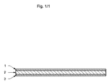
それにより、材料のシーケンスは:まず、金属マニホールド又はフランジを設けた配管のようなインターフェース(1)を設け、次いで、軟質で、可撓性のガスケット層(2)、それから電気絶縁性のガスケット層(3)、それから軟質で可撓性のガスケット(4)、そしてその次にSOCスタック(5)のインターフェースを設ける。 Thereby, the sequence of materials is: firstly providing an interface (1), such as a metal manifold or a pipe with flanges, then a soft, flexible gasket layer (2) and then an electrically insulating gasket layer (3), then provide the soft and flexible gasket (4), and then the interface of the SOC stack (5).
しかしながら、そのような設計により、熱サイクルの間にガスケット層が平面において移動したり、又は、運転の間に振動したり、そしてSOCスタックシステム部材が何らかの移動をしたりする可能性がある。合計で4つのインターフェースが存在し、1−2、2−3、3−4及び4−5で滑りが起こり得る。 However, such a design may cause the gasket layer to move in a plane during thermal cycling, or oscillate during operation, and some movement of the SOC stack system members. There are a total of four interfaces and slips can occur at 1-2, 2-3, 3-4 and 4-5.
インターフェース1−2及び4−5について、材料の組合せは良く知られており、そして、解法は、ASME標準によって推奨されるのと同じであることができるため、例えば、設置インターフェース1及び5(マニホールド、フランジ及びSOCスタック配置インターフェース)の粗度のように従来技術において公知である。
For the interfaces 1-2 and 4-5, the material combinations are well known and the solution can be the same as recommended by the ASME standard, for example the
しかしながら、インターフェース2−3及び3−4については、ガスケット層で挟む組合せにおいて固定する新しい方法が、本発明によって導入される。ガスケット層の一つ又は二つ以上は、シーリング領域中に一つ又は多数の穴、くぼみ又は隆起部を設けて製造される。これは、ガスケット層を切断して成形される時に行うことができる。圧縮下でガスケット層が一緒にサンドイッチされる際、穴又はくぼみを有するガスケット層に隣接するガスケット層は、その際にその穴又はくぼみ内へ突出し、それにより、ガスケット層を互いに固定するのに必要な固定がもたらされる。同様に、隆起部を有するガスケット層に隣接するガスケット層は、圧縮下でガスケット層が一緒にサンドイッチされる時にその隆起部に対向する位置でくぼみによる接合を達成し、これもまた、ガスケット層を互いに固定するのに必要な固定をもたらす。この解法は、例えば、サンドイッチ型のガスケットのための、取り囲む二つのガスケット層よりも合成な、中央のガスケット層に適用できる。このように、一つのガスケット層だけに穴、くぼみ又は隆起部を設ける必要があり、それよりもさらに可撓性である該二つの取り囲むガスケット層は、その際、その穴又はくぼみ内へ突出するか、又は該中央のガスケット層の隆起部が位置する箇所でくぼみにより接合される。それにより、全てのインターフェースが固定され、そして、SOCスタックの運転の間及び熱サイクルの間に平面上で移動できなくなる。 However, for the interfaces 2-3 and 3-4, a new method of securing in combinations sandwiched by gasket layers is introduced by the present invention. One or more of the gasket layers is manufactured with one or more holes, depressions or ridges in the sealing area. This can be done when the gasket layer is cut and formed. When the gasket layer under compression is sandwiched together, the gasket layer adjacent to the gasket layer having a hole or depression protrudes into the hole or depression at that time, thereby required to secure the gasket layer together Is achieved. Similarly, a gasket layer adjacent to a gasket layer having a ridge will achieve a dimple bond at a location opposite the ridge when the gasket layer is sandwiched together under compression, which also reduces the gasket layer. Provides the necessary fixation to fix each other. This solution can be applied to a central gasket layer, for example for a sandwich type gasket, which is more synthetic than the two surrounding gasket layers. Thus, only one gasket layer needs to be provided with holes, depressions or ridges, and the two surrounding gasket layers, which are even more flexible, then project into the holes or depressions . Alternatively, the central gasket layer is joined by indentations where the ridges are located. Thereby, all interfaces are fixed and cannot move on a plane during operation of the SOC stack and during thermal cycling.
本発明の一実施形態において、複数のスタックされたセルを含む固体酸化物形セルスタックシステムは、スタックへのアプリケーション、すなわち、プロセスガスの配管又はプロセスガスのマニホールドを取り付けるための実装用インターフェースを備えたセルスタックを有する。また、スタックに接続するための該アプリケーションは、実装用インターフェース、例えば、フランジを有する。スタックの該アプリケーションに対する気密な接続を達成する一方で、同時に、スタックをその接続されたアプリケーションから電気的に絶縁するために、該実装インターフェースは、スタックの実装用インターフェースと、隣接する該アプリケーションの実装用インターフェースとの間に配置される少なくとも一つのガスケットをさらに含む。 In one embodiment of the present invention, a solid oxide cell stack system including a plurality of stacked cells includes an application interface to the stack, i.e., a mounting interface for attaching process gas piping or a process gas manifold. Cell stack. The application for connecting to the stack also has a mounting interface, for example a flange. In order to achieve a hermetic connection of the stack to the application, while at the same time electrically isolating the stack from its connected application, the implementation interface comprises a stack implementation interface and an adjacent application implementation And at least one gasket disposed between the first and second gaskets.
振動、該実装用インターフェースの表面の欠陥、及び熱由来の移動を相殺するための可撓性を達成するために、ガスケットは、二つの層、すなわち、これらの特徴を具え、かつ、これらを相殺するのに十分可撓性である第一の層及び第三の層を含む。十分に可撓性であるとは、SOCセルスタックシステムの通常の運転及び始動/停止サイクルの間における上述の移動、振動及び表面の欠陥を、破損又は漏れを引き起こすことなく相殺できる、という意味である。 In order to achieve flexibility to counteract vibration, surface defects of the mounting interface, and heat-induced movement, the gasket has two layers, namely these features, and cancels them out. A first layer and a third layer that are sufficiently flexible to perform. Sufficiently flexible means that the aforementioned movement, vibration and surface defects during normal operation and start / stop cycles of the SOC cell stack system can be offset without causing breakage or leakage. is there.
スタックを、実装されたアプリケーションから電気的に絶縁するために、ガスケットは、前記の第一及び第三の層の間に挟まれた、第二のガスケット層をさらに含み、該第二のガスケット層は、SOCセルスタックシステムの通常の運転及び始動/停止サイクルの間におけるセルスタックの短絡、及び、スタックの実装されたアプリケーションに対する電気的接続を防止するのに十分な電気絶縁特性を有する。図1において、この実施形態によるガスケットの横断面図が見られ、符号1及び3は、可撓性の層を示し、そして、符号2は、電気的に絶縁の層を示している。 The gasket further includes a second gasket layer sandwiched between the first and third layers, to electrically insulate the stack from an implemented application. Has sufficient electrical insulation properties to prevent shorting of the cell stack during normal operation and start / stop cycles of the SOC cell stack system and electrical connection to the mounted application of the stack. In FIG. 1, a cross-sectional view of a gasket according to this embodiment can be seen, where 1 and 3 indicate a flexible layer and 2 indicates an electrically insulating layer.
本発明の実施形態では、三つのガスケット層の全てがマイカから製造され、第一及び第三の層は、上述した必要な可撓性を与える特性を備えたマイカ材料から製造されている。第二の層は、該第一及び第三の層よりも可撓性ではなく、必要な電気絶縁性を与える特性を有する。 In embodiments of the present invention, all three gasket layers are made of mica, and the first and third layers are made of mica material with the necessary flexibility properties described above. The second layer is less flexible than the first and third layers and has properties that provide the necessary electrical insulation.
本発明の実施形態において、該第二の層の引っ張り強度は、60〜180N/mm2、好ましくは、90〜150N/mm2である。該第二の層の200℃における圧縮強度は、180〜300N/mm2、好ましくは、220〜260N/mm2である。そして、該第二の層の曲げ強度は、150〜250N/mm2、好ましくは140〜200N/mm2である。
In an embodiment of the present invention, the tensile strength of the second layer is 60 to 180 N / mm2, preferably 90 to 150 N / mm2. The compressive strength of the second layer at 200 ° C. is 180 to 300 N /
本発明の実施形態において、それぞれのガスケット層の厚さは、0.2mm〜15mm、好ましくは、0.4〜5mmである。それぞれの層の厚さは、必要な可撓性、シーリング及び電気絶縁性を達成するように変えることができる。 In an embodiment of the present invention, the thickness of each gasket layer is between 0.2 mm and 15 mm, preferably between 0.4 and 5 mm. The thickness of each layer can be varied to achieve the required flexibility, sealing and electrical insulation.
本発明の実施形態において、少なくとも第一及び第三の層の可撓性は、ガスケット層のそれぞれの間を固定し、そしてさらには、ガスケットと隣接する実装用インターフェースとの間を固定するのに利用される。くぼみ、穴又は隆起部は、それら三つのガスケット層のうちの少なくとも一つ中(すなわち第二の層中)に形成されて、該層を互いに固定させる。 In embodiments of the present invention, the flexibility of at least the first and third layers secures between each of the gasket layers, and furthermore, secures between the gasket and an adjacent mounting interface. Used. Recesses , holes or ridges are formed in at least one of the three gasket layers (ie, in the second layer) to secure the layers together.
本発明のさらなる実施形態において、ガスケットを、該ガスケットと接触して隣接する実装用インターフェースに対して固定して、その実装用インターフェースの平面において移動するのを防止するのに同じ原理が利用される。したがって、穴、隆起部又はくぼみは、ガスケットと接触する実装用インターフェース中に形成される。圧縮下において、これは、ガスケットを実装用インターフェースに対して固定する。 In a further embodiment of the present invention, the same principle is used to secure the gasket against an adjacent mounting interface in contact with the gasket and prevent movement in the plane of the mounting interface. . Thus, holes, ridges or depressions are formed in the mounting interface that contacts the gasket. Under compression, this secures the gasket to the mounting interface.
本発明の実施形態において、ガスケット層のうちの一つ又は二つ以上に接着剤が適用されて、少なくとも組み立て及び該ガスケットをSOCスタックシステムに取り付ける間、該層を簡単に固定する。接着剤は、ガスケットと、隣接する実装用インターフェースのうちの少なくとも一つとの間に適用することもでき、それにより同様に、SOCシステムにおいてガスケットを組み立てる間、構成要素を簡単に固定する。本発明の実施形態において、ガスケットは、SOCスタックと、SOCスタックに接続されるプロセスガスマニホールド(これは、通常、”外部マニホールド”と呼ばれる)との間に取り付けられる。 In embodiments of the present invention, an adhesive is applied to one or more of the gasket layers to easily secure the layers at least during assembly and attaching the gasket to the SOC stack system. The adhesive may also be applied between the gasket and at least one of the adjacent mounting interfaces, thereby also simply securing the components during assembly of the gasket in the SOC system. In an embodiment of the present invention, a gasket is mounted between the SOC stack and a process gas manifold connected to the SOC stack (this is commonly referred to as an "external manifold").
本発明の態様において、積層された複数のセル及び複数の実装用インターフェースを含むSOCスタックシステムが組み立てられる。少なくとも三つの層による、少なくとも一つのサンドイッチ構造のガスケットは、二つの実装用インターフェースのうちの間に位置させる。前記で述べたように、該実装用インターフェースは、SOCスタック及びマニホールドとフランジ付きの配管のようなプロセスガス接続部を含んでいてもよい。該組み立ては、可撓性のガスケット材料を挟んでいる第一及び第三の、二つのガスケット層を製造する工程を含む。上述したように、該材料は、SOCセルスタックの通常の運転及び始動/停止段階の間に起こる振動、実装用インターフェースの表面の欠陥及び熱に起因する移動、及びその他の移動を相殺するのに十分でなければならない。ガスケット層は、間に取り付けられる二つの実装用インターフェースを物理的に整合させて製造される。電気絶縁性のさらなる、第二のガスケット層もまた、第一及び第三のガスケット層と同様に、二つの実装用インターフェースを物理的に整合させて製造される。次に、それら三つのガスケット層を、二つの可撓性の層の間に電気絶縁性の層を挟むように、1−2−3の順に組み立てる。ガスケットのサンドイッチ構造体を組み立てた後、該サンドイッチを、二つの実装用インターフェース(すなわち、マニホールドとSOCスタックと)の間に配置し、その一つの方法は、二つの実装インターフェースのうちの一方の上、例えば、SOCスタックの実装用インターフェースの上にガスケットのサンドイッチ構造体を配置することである。最後に、ガスケットが、それら二つの実装用インターフェースの間に位置し、圧縮力が付与されるよう、他方の実装用インターフェース、例えば、第一の実装用インターフェースに対向するガスケットの表面上にマニホールドを取り付け、それにより、ガスケットはそれら二つの実装用インターフェースの間で圧縮され、かつ、気密なシーリングが達成される。 In an aspect of the invention, an SOC stack system including a plurality of stacked cells and a plurality of mounting interfaces is assembled. At least one sandwich gasket with at least three layers is located between the two mounting interfaces. As noted above, the mounting interface may include process gas connections such as SOC stacks and manifold and flanged tubing. The assembling includes manufacturing first and third two gasket layers sandwiching a flexible gasket material. As mentioned above, the material is used to offset vibrations that occur during the normal operation and start / stop phases of the SOC cell stack, movements due to surface defects and heat of the mounting interface, and other movements. Must be enough. The gasket layer is manufactured by physically matching the two mounting interfaces mounted between them. An additional, electrically insulating, second gasket layer, like the first and third gasket layers, is also manufactured with the two mounting interfaces physically aligned. Next, the three gasket layers are assembled in the order of 1-2-3 such that an electrically insulating layer is sandwiched between the two flexible layers. After assembling the sandwich structure of the gasket, the sandwich is placed between two mounting interfaces (ie, the manifold and the SOC stack), one method of which is to place one of the two mounting interfaces on one of the two mounting interfaces. For example, to place the gasket sandwich structure over the mounting interface of the SOC stack. Finally, a manifold is placed on the surface of the gasket opposite the other mounting interface, e.g., the first mounting interface, such that a gasket is located between the two mounting interfaces and a compressive force is applied. Attachment, whereby the gasket is compressed between the two mounting interfaces and a hermetic seal is achieved.
本発明のこの態様のさらなる実施形態では、三層のガスケットのサンドイッチ構造体が組み立てられる前に、少なくともSOCスタックシステムが組み立てられるまで該層を一緒に固定するために、ガスケット層の少なくとも二つの表面に接着剤が適用される。 In a further embodiment of this aspect of the invention, at least two surfaces of the gasket layer are fixed before the three-layer gasket sandwich structure is assembled, to secure the layers together at least until the SOC stack system is assembled. An adhesive is applied.
この組み立て工程のさらなる実施形態では、三つのガスケット層を組み立てる前に、それら層のうちの少なくとも一つにくぼみ又は穴が形成される。これにより、ガスケットが圧縮されると、スタックシステムの運転及び熱サイクルの間、相対するガスケット層が互いに固定される。該穴又はくぼみは、ガスケットの第二かつそれほど可撓性でない層に設けることができ、これは、最も簡単な製造である。 In a further embodiment of this assembling process, before assembling the three gasket layers, at least one of the layers is formed with a depression or hole. This locks the opposing gasket layers together during operation and thermal cycling of the stack system as the gasket is compressed. The holes or depressions can be provided in the second and less flexible layer of the gasket, which is the simplest manufacture.
該組み立て工程の実施形態において、ガスケットを圧縮する実装用インターフェースのうちの少なくとも一つに、穴、くぼみ又は隆起部が設けられて、ガスケットが接触する実装用インターフェースに対してそれが固定される。該ガスケット層はマイカから製造でき、そのガスケットの第二の層は、第一及び第三の層ほど可撓性ではいが、電気絶縁性である。 In an embodiment of the assembling process, at least one of the mounting interfaces for compressing the gasket is provided with a hole, depression or ridge to secure it to the mounting interface with which the gasket contacts. The gasket layer can be made from mica, and the second layer of the gasket is electrically insulating, although not as flexible as the first and third layers.
本発明の特徴
1.スタックされた複数のセルユニット及び実装インターフェースを含む固体酸化物形セルスタックシステムであり、該実装インターフェースは、少なくとも一つのガスケットを含み、該ガスケットは、少なくとも三つの層のサンドイッチ構造を含み、その第一及び第三の層は、振動、該実装インターフェースの表面の欠陥、及び熱に起因する移動を相殺するのに十分可撓性である該構造、及び該第一の層と第三の層の間に位置する第二の絶縁層である、固体酸化物形セルスタックシステム。
Features of the present invention A solid oxide cell stack system including a plurality of stacked cell units and a mounting interface, the mounting interface including at least one gasket, the gasket including a sandwich structure of at least three layers, wherein The first and third layers are sufficiently flexible to offset vibrations, surface defects of the mounting interface, and heat-induced movement, and the structure of the first and third layers A solid oxide cell stack system, the second insulating layer in between.
2.前記層がマイカから製造されており、前記第一及び第三の層が、前記第二の層よりも可撓性である、上記の1に記載の固体酸化物形セルスタックシステム。
2. The solid oxide cell stack system of
3.前記第二の層の引っ張り強度が、60〜180N/mm2、好ましくは90〜150N/mm2である、上記の1又は2に記載の固体酸化物形セルスタックシステム。 3. The solid oxide cell stack system according to the above 1 or 2, wherein the tensile strength of the second layer is 60 to 180 N / mm2, preferably 90 to 150 N / mm2.
4.200℃における前記第二の層の圧縮強度が180〜300N/mm2、好ましくは220〜260N/mm2である、上記の1〜3のいずれか一つに記載の固体酸化物形セルスタックシステム。
4. The solid oxide cell stack system according to any one of the
5.前記第二の層の曲げ強度が、150〜250N/mm2、好ましくは140〜200N/mm2である、上記の1〜4のいずれか一つに記載の固体酸化物形セルスタックシステム。
5. The solid oxide cell stack system according to any one of the
6.第一、第二及び第三それぞれの層の厚さが、0.2mm〜15mm、好ましくは0.4mm〜5mmである、上記の1〜5のいずれか一つに記載の固体酸化物形セルスタックシステム。
6. The solid oxide cell according to any one of the
7.前記三つの層のうちの少なくとも一つに、該層のそれぞれの互いに対する固定を提供するために、くぼみ、穴又は隆起が形成されている、上記の1〜6のいずれか一つに記載の固体酸化物形セルスタックシステム。 7. A method according to any one of the preceding claims, wherein at least one of the three layers is provided with a depression , hole or bump to provide anchoring of each of the layers to each other. Solid oxide cell stack system.
8.該層のそれぞれの互いに対する固定を提供するために、前記第二の層に穴が形成されている、上記の7に記載の固体酸化物形セルスタックシステム。 8. The solid oxide cell stack system of claim 7, wherein holes are formed in the second layer to provide anchoring of each of the layers to one another.
9.前記ガスケットに接触する前記実装インターフェースのうちの少なくとも一つに、該接触する実装インターフェースに対するガスケットの固定を提供するために、くぼみ、穴又は隆起部が形成されている、上記の1〜8のいずれか一つに記載の固体酸化物形セルスタックシステム。 9. Any of the preceding claims, wherein at least one of the mounting interfaces contacting the gasket is formed with a recess , hole or ridge to provide a securement of the gasket to the contacting mounting interface. A solid oxide cell stack system according to any one of the preceding claims.
10.前記三つの層の間に接着剤が適用される、上記の1〜9のいずれか一つに記載の固体酸化物形セルスタックシステム。
10. The solid oxide cell stack system according to any one of the
11.前記ガスケットが、前記セルスタックとプロセスガスマニホールドとの間に実装される、上記の1〜10のいずれか一つに記載の固体酸化物形セルスタックシステム。
11. The solid oxide cell stack system according to any one of the
12.スタックされた複数のセルユニット及び複数の実装インターフェースを含み、二つの実装インターフェースの間に配置すべき少なくとも三つの層を備えた、少なくとも一つのサンドイッチ構造のガスケットを含む、固体酸化物形セルスタックシステムを組み立てる方法であって、下記の工程、
・該ガスケットの第一及び第三のガスケット層を、可撓性のガスケット材料で製造する工程であり、該材料は、前記二つの実装インターフェースに対して物理的に整合させるために、振動、該実装インターフェースの表面の欠陥及び熱に起因する移動を相殺するのに十分可撓性である、工程;
・前記二つの実装インターフェース及び第一及び第二のガスケット層に対して物理的に整合させるために、第二のガスケットガスケット層を絶縁材料で製造する工程;
・前記第二のガスケット層を前記第一及び第三のガスケット層の間に挟んで前記三つの層を組み立てる工程;
・該組み立てたガスケットを、前記実装インターフェースのうちの一方の上に配置する工程;
・前記二つの実装インターフェースのうちの他方を実装する工程;及び
・前記二つの実装インターフェースの間で前記ガスケットに圧縮を適用する工程、
を含む、上記の方法。
12. A solid oxide cell stack system including at least one sandwich gasket including a plurality of stacked cell units and a plurality of mounting interfaces and having at least three layers to be disposed between the two mounting interfaces. The following steps,
Manufacturing the first and third gasket layers of the gasket with a flexible gasket material, wherein the material is vibrated to provide physical alignment with the two mounting interfaces; A process that is sufficiently flexible to offset surface-induced and thermal-induced movement of the mounting interface;
Manufacturing a second gasket gasket layer from an insulating material to physically match the two mounting interfaces and the first and second gasket layers;
Assembling the three layers with the second gasket layer sandwiched between the first and third gasket layers;
Placing the assembled gasket on one of the mounting interfaces;
Mounting the other of the two mounting interfaces; and applying compression to the gasket between the two mounting interfaces;
The above method, comprising:
13.前記三つのガスケットの層を組み立てる前に、前記ガスケットの層の少なくとも二つの表面に接着剤が適用される、上記の12に記載の方法。 13. 13. The method of claim 12, wherein an adhesive is applied to at least two surfaces of the gasket layer before assembling the three gasket layers.
14.前記三つの層のうちの少なくとも一つに、該層のそれぞれの互いに対する固定を提供するためにくぼみ又は穴が形成される、上記の12又は13に記載の方法。 14. 14. The method of claim 12 or 13, wherein at least one of the three layers is formed with a depression or hole to provide anchoring of each of the layers to each other.
15.前記第二の層に、層のそれぞれの互いに対する固定を提供するために穴が形成される、上記の12〜14のいずれか一つに記載の方法。 15. A method according to any one of claims 12 to 14, wherein holes are formed in the second layer to provide anchoring of each of the layers to each other.
16.前記ガスケットに接触する前記実装インターフェースのうちの少なくとも一つに、該接触する実装インターフェースに対するガスケットの固定を提供するために、くぼみ、穴又は隆起部が形成される、上記の12〜15のいずれか一つに記載の方法。 16. Any of the preceding claims 12-15, wherein at least one of the mounting interfaces contacting the gasket is formed with a depression , hole or ridge to provide a securement of the gasket to the contacting mounting interface. The method according to one.
17.前記ガスケットの層がマイカから製造され、前記第一及び第三のガスケットの層が、前記第二の層よりも可撓性である、上記の12〜16のいずれか一つに記載の方法。
本願は特許請求の範囲に記載の発明に係るものであるが、本願の開示は以下も包含する。
1.
スタックされた複数のセルユニット及び実装インターフェースを含む固体酸化物形セルスタックシステムであり、該実装インターフェースは、少なくとも一つのガスケットを含み、該ガスケットは、振動、該実装インターフェースの表面の欠陥、及び熱に起因する移動を相殺するのに十分可撓性である第一及び第三の可撓性の層と、該第一の層と第三の層の間に位置する第二の電気絶縁層との少なくとも三つの層のサンドイッチ構造を含む、固体酸化物形セルスタックシステム。
2.
前記層はマイカから製造されており、前記第一及び第三の層は、前記第二の層よりも可撓性である、上記1に記載の固体酸化物形セルスタックシステム。
3.
前記第二の層の引っ張り強度が、60〜180N/mm2、好ましくは90〜150N/mm2である、上記1又は2に記載の固体酸化物形セルスタックシステム。
4.
200℃における前記第二の層の圧縮強度が180〜300N/mm2、好ましくは220〜260N/mm2である、上記1〜3のいずれか一つに記載の固体酸化物形セルスタックシステム。
5.
前記第二の層の曲げ強度が、150〜250N/mm2、好ましくは140〜200N/mm2である、上記1〜4のいずれか一つに記載の固体酸化物形セルスタックシステム。
6.
第一、第二及び第三それぞれの層の厚さが、0.2mm〜15mm、好ましくは0.4mm〜5mmである、上記1〜5のいずれか一つに記載の固体酸化物形セルスタックシステ。
7.
前記三つの層のうちの少なくとも一つに、該層のそれぞれの互いに対する固定を提供するために、くぼみ、穴又は隆起が形成されている、上記1〜6のいずれか一つに記載の固体酸化物形セルスタックシステム。
8.
該層のそれぞれの互いに対する固定を提供するために、前記第二の層に穴が形成されている、上記7に記載の固体酸化物形セルスタックシステム。
9.
前記ガスケットに接触する前記実装インターフェースのうちの少なくとも一つに、該接触する実装インターフェースに対するガスケットの固定を提供するために、くぼみ、穴又は隆起部が形成されている、上記1〜8のいずれか一つに記載の固体酸化物形セルスタックシステム。
10.
前記三つの層の間に接着剤が適用される、上記1〜9のいずれか一つに記載の固体酸化物形セルスタックシステム。
11.
前記ガスケットが、前記セルスタックとプロセスガスマニホールドとの間に実装される、上記1〜10のいずれか一つに記載の固体酸化物形セルスタックシステム。
12.
スタックされた複数のセルユニット及び複数の実装インターフェースを含み、二つの実装インターフェースの間に配置すべき少なくとも三つの層を備えた、少なくとも一つのサンドイッチ構造のガスケットを含む、固体酸化物形セルスタックシステムを組み立てる方法であって、下記の工程、
・該ガスケットの第一及び第三のガスケット層を、可撓性のガスケット材料で製造する工程であり、該材料は、前記二つの実装インターフェースに対して物理的に整合させるために、振動、該実装インターフェースの表面の欠陥及び熱に起因する移動を相殺するのに十分可撓性である、工程;
・前記二つの実装インターフェース及び第一及び第二のガスケット層に対して物理的に整合させるために、第二のガスケット層を電気絶縁材料で製造する工程;
・前記第二のガスケット層を前記第一及び第三のガスケット層の間に挟んで前記三つの層を組み立てる工程;
・該組み立てたガスケットを、前記二つの実装インターフェースのうちの一方の上に配置する工程;
・前記二つの実装インターフェースのうちの他方を実装する工程;及び
・前記二つの実装インターフェースの間で前記ガスケットに圧縮を適用する工程、
を含む、上記の方法。
13.
前記三つのガスケットの層を組み立てる前に、前記ガスケットの層の少なくとも二つの表面に接着剤が適用される、上記12に記載の方法。
14.
前記三つの層のうちの少なくとも一つに、該層のそれぞれの互いに対する固定を提供するためにくぼみ又は穴が形成される、上記12又は13に記載の方法。
15.
前記第二の層に、層のそれぞれの互いに対する固定を提供するために穴が形成される、上記12〜14のいずれか一つに記載の方法。
16.
前記ガスケットに接触する前記実装インターフェースのうちの少なくとも一つに、該接触する実装インターフェースに対するガスケットの固定を提供するために、くぼみ、穴又は隆起部が形成される、上記12〜15のいずれか一つに記載の方法。
17.
前記ガスケットの層がマイカから製造され、前記第一及び第三のガスケットの層が、前記第二の層よりも可撓性である、上記12〜16のいずれか一つに記載の方法。
17. The method of any of claims 12 to 16, wherein the gasket layer is made of mica, and wherein the first and third gasket layers are more flexible than the second layer.
Although the present application relates to the invention described in the claims, the disclosure of the present application also includes the following.
1.
A solid oxide cell stack system including a plurality of stacked cell units and a mounting interface, wherein the mounting interface includes at least one gasket, wherein the gasket includes vibration, surface defects of the mounting interface, and heat. A first and a third flexible layer that are sufficiently flexible to offset movement due to a second electrically insulating layer located between the first and third layers. A solid oxide cell stack system, comprising a sandwich structure of at least three layers.
2.
The solid oxide cell stack system of
3.
The solid oxide cell stack system according to 1 or 2, wherein the second layer has a tensile strength of 60 to 180 N / mm2, preferably 90 to 150 N / mm2.
4.
The solid oxide cell stack system according to any one of the
5.
The solid oxide cell stack system according to any one of the
6.
The solid oxide cell stack according to any one of the
7.
The solid of any one of the preceding claims, wherein at least one of the three layers is formed with a depression, hole or bump to provide anchoring of each of the layers to each other. Oxide cell stack system.
8.
The solid oxide cell stack system of claim 7, wherein holes are formed in the second layer to provide anchoring of each of the layers to one another.
9.
Any of the preceding claims, wherein at least one of the mounting interfaces contacting the gasket is formed with a depression, hole or ridge to provide a securement of the gasket to the contacting mounting interface. A solid oxide cell stack system according to one of the preceding claims.
10.
The solid oxide cell stack system according to any one of
11.
The solid oxide cell stack system according to any one of the
12.
A solid oxide cell stack system including at least one sandwich gasket including a plurality of stacked cell units and a plurality of mounting interfaces, and having at least three layers to be disposed between the two mounting interfaces. The following steps,
Manufacturing the first and third gasket layers of the gasket with a flexible gasket material, the material being oscillated to physically match the two mounting interfaces; A process that is sufficiently flexible to offset surface-induced and heat-induced migration of the mounting interface;
Manufacturing the second gasket layer from an electrically insulating material to physically match the two mounting interfaces and the first and second gasket layers;
Assembling the three layers with the second gasket layer sandwiched between the first and third gasket layers;
Placing the assembled gasket on one of the two mounting interfaces;
Mounting the other of the two mounting interfaces; and
Applying compression to the gasket between the two mounting interfaces;
The above method, comprising:
13.
13. The method of claim 12, wherein an adhesive is applied to at least two surfaces of the gasket layers before assembling the three gasket layers.
14.
14. The method of claim 12 or 13, wherein at least one of the three layers is formed with a depression or hole to provide anchoring of each of the layers to each other.
15.
15. The method according to any one of claims 12 to 14, wherein holes are formed in the second layer to provide anchoring of each of the layers to each other.
16.
Any one of the preceding claims 12 to 15, wherein at least one of the mounting interfaces contacting the gasket is formed with a recess, hole or ridge to provide a securement of the gasket to the contacting mounting interface. The method described in one.
17.
The method of any of claims 12 to 16, wherein the layers of the gasket are manufactured from mica, and the layers of the first and third gaskets are more flexible than the second layer.
Claims (15)
・該ガスケットの第一及び第三のガスケット層を、可撓性のガスケット材料で製造する工程であり、該材料は、前記二つの実装インターフェースに対して物理的に整合させるために、振動、該実装インターフェースの表面の欠陥及び熱に起因する移動を相殺するのに十分可撓性である、工程;
・前記二つの実装インターフェース及び第一及び第三のガスケット層に対して物理的に整合させるために、第二のガスケット層を電気絶縁材料で製造する工程;
・前記第二のガスケット層を前記第一及び第三のガスケット層の間に挟んで前記三つの層を組み立てる工程;
・該組み立てたガスケットを、前記二つの実装インターフェースのうちの一方の上に配置する工程;
・前記二つの実装インターフェースのうちの他方を実装する工程;及び
・前記二つの実装インターフェースの間で前記ガスケットに圧縮を適用する工程、
を含み、前記各ガスケットの層がマイカから製造され、前記第一及び第三のガスケットの層が、前記第二の層よりも可撓性が高い、上記の方法。 A solid oxide cell stack system including at least one sandwich gasket including a plurality of stacked cell units and a plurality of mounting interfaces, and having at least three layers to be disposed between the two mounting interfaces. The following steps,
Manufacturing the first and third gasket layers of the gasket with a flexible gasket material, wherein the material is vibrated to provide physical alignment with the two mounting interfaces; A process that is sufficiently flexible to offset surface-induced and thermal-induced movement of the mounting interface;
Manufacturing a second gasket layer of an electrically insulating material to physically match the two mounting interfaces and the first and third gasket layers;
Assembling the three layers with the second gasket layer sandwiched between the first and third gasket layers;
Placing the assembled gasket on one of the two mounting interfaces;
Mounting the other of the two mounting interfaces; and applying compression to the gasket between the two mounting interfaces;
Only including the layers of the gasket is made from mica, a layer of the first and third gasket, which has a greater flexibility than the second layer, the above methods.
Applications Claiming Priority (3)
| Application Number | Priority Date | Filing Date | Title |
|---|---|---|---|
| EP14163492.3A EP2927999B1 (en) | 2014-04-04 | 2014-04-04 | Three layered electrically insulating gasket for SOC unit |
| EP14163492.3 | 2014-04-04 | ||
| PCT/EP2015/056855 WO2015150306A1 (en) | 2014-04-04 | 2015-03-30 | Three layered electrically insulating gasket for sofc unit |
Publications (3)
| Publication Number | Publication Date |
|---|---|
| JP2017517837A JP2017517837A (en) | 2017-06-29 |
| JP2017517837A5 JP2017517837A5 (en) | 2019-10-03 |
| JP6644004B2 true JP6644004B2 (en) | 2020-02-12 |
Family
ID=50434080
Family Applications (1)
| Application Number | Title | Priority Date | Filing Date |
|---|---|---|---|
| JP2016560690A Active JP6644004B2 (en) | 2014-04-04 | 2015-03-30 | Electrically insulating three-layer gasket for SFOC unit |
Country Status (11)
| Country | Link |
|---|---|
| US (1) | US10205179B2 (en) |
| EP (1) | EP2927999B1 (en) |
| JP (1) | JP6644004B2 (en) |
| KR (1) | KR102316138B1 (en) |
| CN (1) | CN106463745B (en) |
| AU (1) | AU2015239662B2 (en) |
| CA (1) | CA2944252C (en) |
| DK (1) | DK2927999T3 (en) |
| EA (1) | EA201691965A1 (en) |
| ES (1) | ES2643601T3 (en) |
| WO (1) | WO2015150306A1 (en) |
Families Citing this family (4)
| Publication number | Priority date | Publication date | Assignee | Title |
|---|---|---|---|---|
| JP2019503030A (en) * | 2015-11-13 | 2019-01-31 | サン−ゴバン セラミックス アンド プラスティクス,インコーポレイティド | Thermal insulation and compression of high temperature equipment |
| EP4089206A1 (en) * | 2020-01-08 | 2022-11-16 | Panasonic Intellectual Property Management Co., Ltd. | Compression apparatus |
| US11374232B2 (en) * | 2020-05-05 | 2022-06-28 | Bloom Energy Corporation | Dielectric separator for fuel cell stack assembly and manufacturing method thereof |
| CN114580111B (en) * | 2022-03-11 | 2022-10-25 | 武汉雄韬氢雄燃料电池科技有限公司 | Air intake manifold design method based on double-stack flow distribution consistency |
Family Cites Families (14)
| Publication number | Priority date | Publication date | Assignee | Title |
|---|---|---|---|---|
| JPS6386366A (en) * | 1986-09-30 | 1988-04-16 | Toshiba Corp | Solid electrolyte fuel cell |
| JP2995604B2 (en) * | 1993-07-30 | 1999-12-27 | 三洋電機株式会社 | Gas seal material for solid electrolyte fuel cells |
| US7799419B2 (en) * | 2002-12-24 | 2010-09-21 | Versa Power Systems, Ltd. | High temperature gas seals |
| DE10302124A1 (en) * | 2003-01-21 | 2004-07-29 | Bayerische Motoren Werke Ag | Fuel cell is constructed with a stack of cell elements separated by a metal oxide sealing layer |
| US7553579B2 (en) * | 2003-04-04 | 2009-06-30 | Versa Power Systems Ltd. | Solid oxide fuel cell stack with floating cells |
| US7485386B2 (en) | 2004-05-27 | 2009-02-03 | Siemens Energy, Inc. | Flexible ceramic gasket for SOFC generator |
| US7785725B2 (en) | 2004-12-03 | 2010-08-31 | Delphi Technologies, Inc. | Compound for a solid oxide fuel cell stack gasket |
| DE102009008717B4 (en) * | 2009-02-12 | 2013-07-18 | Elringklinger Ag | Method for producing an electrically insulating sealing arrangement and sealing arrangement for sealing between two components of a fuel cell stack |
| JP5399962B2 (en) * | 2010-03-29 | 2014-01-29 | 日本特殊陶業株式会社 | Solid oxide fuel cell and method for producing the same |
| JP2012036283A (en) * | 2010-08-05 | 2012-02-23 | Toshiba Corp | Ceramic seal material and method of using the same |
| JP5451653B2 (en) * | 2011-01-06 | 2014-03-26 | 日本電信電話株式会社 | Gas seal material |
| FR2974401B1 (en) * | 2011-04-22 | 2013-06-14 | Commissariat Energie Atomique | METALLIC SEAL SEAL WITH CERAMIC WAVE |
| JP2013061056A (en) * | 2011-09-15 | 2013-04-04 | Nissan Motor Co Ltd | Gas seal member, fuel cell and method for manufacturing fuel cell |
| MX2011013927A (en) * | 2011-12-16 | 2013-06-18 | Viakable S A De C V | Flame and oil resistant halogen-free composition. |
-
2014
- 2014-04-04 ES ES14163492.3T patent/ES2643601T3/en active Active
- 2014-04-04 DK DK14163492.3T patent/DK2927999T3/en active
- 2014-04-04 EP EP14163492.3A patent/EP2927999B1/en active Active
-
2015
- 2015-03-30 EA EA201691965A patent/EA201691965A1/en unknown
- 2015-03-30 AU AU2015239662A patent/AU2015239662B2/en active Active
- 2015-03-30 KR KR1020167026793A patent/KR102316138B1/en active IP Right Grant
- 2015-03-30 JP JP2016560690A patent/JP6644004B2/en active Active
- 2015-03-30 WO PCT/EP2015/056855 patent/WO2015150306A1/en active Application Filing
- 2015-03-30 CA CA2944252A patent/CA2944252C/en active Active
- 2015-03-30 CN CN201580018181.3A patent/CN106463745B/en active Active
- 2015-03-30 US US15/122,479 patent/US10205179B2/en active Active
Also Published As
| Publication number | Publication date |
|---|---|
| AU2015239662B2 (en) | 2019-07-04 |
| CN106463745B (en) | 2019-08-20 |
| AU2015239662A1 (en) | 2016-10-06 |
| EA201691965A1 (en) | 2017-04-28 |
| CA2944252A1 (en) | 2015-10-08 |
| JP2017517837A (en) | 2017-06-29 |
| EP2927999A1 (en) | 2015-10-07 |
| DK2927999T3 (en) | 2017-10-23 |
| CA2944252C (en) | 2020-07-14 |
| EP2927999B1 (en) | 2017-07-26 |
| US10205179B2 (en) | 2019-02-12 |
| ES2643601T3 (en) | 2017-11-23 |
| CN106463745A (en) | 2017-02-22 |
| KR102316138B1 (en) | 2021-10-25 |
| US20170084930A1 (en) | 2017-03-23 |
| KR20160142296A (en) | 2016-12-12 |
| WO2015150306A1 (en) | 2015-10-08 |
Similar Documents
| Publication | Publication Date | Title |
|---|---|---|
| JP6644004B2 (en) | Electrically insulating three-layer gasket for SFOC unit | |
| JP2009505370A (en) | Solid oxide fuel cell stack for mobile generators | |
| JP2019527922A (en) | Planar solid oxide fuel unit cell and stack | |
| JP2006120589A (en) | Flat plate lamination type fuel cell | |
| WO2006077762A1 (en) | Flat laminate type fuel cell and fuel cell stack | |
| GB2535242A (en) | Fuel cell stack | |
| JPWO2008123570A1 (en) | Electrochemical equipment | |
| JP4573526B2 (en) | Solid oxide fuel cell | |
| JP4842630B2 (en) | Solid oxide fuel cell | |
| JP4900364B2 (en) | Fuel cell | |
| JP2008251236A (en) | Flat lamination type fuel cell | |
| JP6118230B2 (en) | Fuel cell stack | |
| JP6621541B2 (en) | Electrochemical reaction cell stack, interconnector-electrochemical reaction single cell complex, and method for producing electrochemical reaction cell stack | |
| CN113632270B (en) | Electrochemical cell, electrochemical cell stack, method for producing an electrochemical cell, and method for producing an electrochemical cell stack | |
| JP2020170631A (en) | Electrochemical reaction cell stack | |
| JP4512845B2 (en) | Fuel cell manifold mechanism | |
| JP6917339B2 (en) | Electrochemical reaction unit and electrochemical reaction cell stack | |
| JP7023898B2 (en) | Electrochemical reaction cell stack | |
| JP4373365B2 (en) | Flat type solid oxide fuel cell stack | |
| JP4373364B2 (en) | Flat type solid oxide fuel cell stack | |
| JP6867974B2 (en) | Electrochemical reaction unit and electrochemical reaction cell stack | |
| JP2024116832A (en) | Electrochemical reaction unit cell | |
| JP2014143052A (en) | Solid electrolyte fuel cell unit and method for manufacturing the same | |
| JP2022017724A (en) | Electrochemical reaction cell stack | |
| JP2000100455A (en) | Manufacture of solid electrolyte fuel cell |
Legal Events
| Date | Code | Title | Description |
|---|---|---|---|
| A621 | Written request for application examination |
Free format text: JAPANESE INTERMEDIATE CODE: A621 Effective date: 20180329 |
|
| A131 | Notification of reasons for refusal |
Free format text: JAPANESE INTERMEDIATE CODE: A131 Effective date: 20190327 |
|
| A601 | Written request for extension of time |
Free format text: JAPANESE INTERMEDIATE CODE: A601 Effective date: 20190625 |
|
| A524 | Written submission of copy of amendment under article 19 pct |
Free format text: JAPANESE INTERMEDIATE CODE: A524 Effective date: 20190821 |
|
| A521 | Request for written amendment filed |
Free format text: JAPANESE INTERMEDIATE CODE: A523 Effective date: 20190822 |
|
| TRDD | Decision of grant or rejection written | ||
| A01 | Written decision to grant a patent or to grant a registration (utility model) |
Free format text: JAPANESE INTERMEDIATE CODE: A01 Effective date: 20191225 |
|
| A61 | First payment of annual fees (during grant procedure) |
Free format text: JAPANESE INTERMEDIATE CODE: A61 Effective date: 20200107 |
|
| R150 | Certificate of patent or registration of utility model |
Ref document number: 6644004 Country of ref document: JP Free format text: JAPANESE INTERMEDIATE CODE: R150 |
|
| R250 | Receipt of annual fees |
Free format text: JAPANESE INTERMEDIATE CODE: R250 |
|
| R250 | Receipt of annual fees |
Free format text: JAPANESE INTERMEDIATE CODE: R250 |