JP6635775B2 - Ink jet recording device - Google Patents
Ink jet recording device Download PDFInfo
- Publication number
- JP6635775B2 JP6635775B2 JP2015239518A JP2015239518A JP6635775B2 JP 6635775 B2 JP6635775 B2 JP 6635775B2 JP 2015239518 A JP2015239518 A JP 2015239518A JP 2015239518 A JP2015239518 A JP 2015239518A JP 6635775 B2 JP6635775 B2 JP 6635775B2
- Authority
- JP
- Japan
- Prior art keywords
- ink
- tank
- ink tank
- stirring
- reserve tank
- Prior art date
- Legal status (The legal status is an assumption and is not a legal conclusion. Google has not performed a legal analysis and makes no representation as to the accuracy of the status listed.)
- Active
Links
Images


Classifications
-
- B—PERFORMING OPERATIONS; TRANSPORTING
- B41—PRINTING; LINING MACHINES; TYPEWRITERS; STAMPS
- B41J—TYPEWRITERS; SELECTIVE PRINTING MECHANISMS, i.e. MECHANISMS PRINTING OTHERWISE THAN FROM A FORME; CORRECTION OF TYPOGRAPHICAL ERRORS
- B41J2/00—Typewriters or selective printing mechanisms characterised by the printing or marking process for which they are designed
- B41J2/005—Typewriters or selective printing mechanisms characterised by the printing or marking process for which they are designed characterised by bringing liquid or particles selectively into contact with a printing material
- B41J2/01—Ink jet
- B41J2/17—Ink jet characterised by ink handling
- B41J2/175—Ink supply systems ; Circuit parts therefor
- B41J2/17503—Ink cartridges
- B41J2/17513—Inner structure
-
- B—PERFORMING OPERATIONS; TRANSPORTING
- B41—PRINTING; LINING MACHINES; TYPEWRITERS; STAMPS
- B41J—TYPEWRITERS; SELECTIVE PRINTING MECHANISMS, i.e. MECHANISMS PRINTING OTHERWISE THAN FROM A FORME; CORRECTION OF TYPOGRAPHICAL ERRORS
- B41J2/00—Typewriters or selective printing mechanisms characterised by the printing or marking process for which they are designed
- B41J2/005—Typewriters or selective printing mechanisms characterised by the printing or marking process for which they are designed characterised by bringing liquid or particles selectively into contact with a printing material
- B41J2/01—Ink jet
- B41J2/17—Ink jet characterised by ink handling
- B41J2/175—Ink supply systems ; Circuit parts therefor
Landscapes
- Ink Jet (AREA)
Description
本発明は、リザーブタンクを有するインク供給装置及びインクジェット記録装置に関する。 The present invention relates to an ink supply device having a reserve tank and an ink jet recording device.
近年、生産装置として、リザーブタンクを備えたインクジェット記録装置が広く使用されている。このようなインクジェット記録装置では、インクタンクが空になってもリザーブタンク内のインクを用いて記録動作を続ける(以下、「ストップレス記録」と称する)ことができる。また、リザーブタンク内のインクを用いて記録動作を継続している間にインクタンクの交換も可能である。 2. Description of the Related Art In recent years, an ink jet recording apparatus having a reserve tank has been widely used as a production apparatus. In such an ink jet recording apparatus, even when the ink tank is empty, the recording operation can be continued using the ink in the reserve tank (hereinafter, referred to as “stopless recording”). Further, the ink tank can be replaced while the recording operation is continued using the ink in the reserve tank.
一方、インクジェット記録装置に使用されるインクは、放置によって溶液(インク)中のインク成分が沈降し、インクタンク内のインク濃度分布が不均一になる場合がある。特に、顔料インクを使用したインクジェット記録装置では、このような問題がより発生しやすくなる。このため、インクジェット記録装置では、定期的にインクタンクやリザーブタンク内のインクを撹拌する必要がある。 On the other hand, in the ink used in the ink jet recording apparatus, the ink component in the solution (ink) may be settled by leaving the ink, and the ink concentration distribution in the ink tank may become uneven. In particular, in an ink jet recording apparatus using a pigment ink, such a problem is more likely to occur. For this reason, in the ink jet recording apparatus, it is necessary to periodically stir the ink in the ink tank and the reserve tank.
例えば、特許文献1に開示されたインクジェット記録装置(図12(a)を参照する)は、上下に配置されたインクタンク130とサブタンク330’(リザーブタンク)を備えている。また、インクタンク130とサブタンク330’の間には、第1の流路(インク導入針321側の流路)と第2の流路(空気導入針322側の流路)が設けられており、それぞれの流路によってインクタンク130とサブタンク330’が連通されている。また、インクタンク130からサブタンク330’へインクが流れるように、サブタンク330’内において、第1流路の下端が第2流路の下端よりも下方に配置されている。
For example, an ink jet recording apparatus disclosed in Patent Document 1 (see FIG. 12A) includes an
これにより、水頭差に基づき第2流路を通じてサブタンク内の空気がインクタンクへ移動されると共に、第1流路を通じてインクタンク130内のインクがサブタンク330’へ自動的に供給される。
Accordingly, the air in the sub tank is moved to the ink tank through the second flow path based on the head difference, and the ink in the
特許文献1の発明では、インクの撹拌手段として、第1流路(インク導入針321側の流路)においてシリンダ500内に往復移動するピストン510を備えたポンプ機構(図12(b)を参照する)が配置されている。
In the invention of
このポンプ機構の動作によって、インクがインクタンク130から第1流路321を通じてサブタンク330’へ流れ、更にサブタンク330’に溜まったインクが第2流路322を通じてインクタンク130へ流れる(戻される)。このように、ポンプ機構の動作を繰り返すことによって、インクタンク130とサブタンク330’の間でインクが循環されて撹拌される。
By the operation of the pump mechanism, the ink flows from the
特許文献1の記録装置では、ポンプ機構によってインクタンク内のインクが少しずつサブタンクに移動されて、更にサブタンク内で薄められて撹拌される。
In the recording apparatus of
一方、インクタンクからサブタンクにインクの移動によって、インクタンク内に微小な負圧が生じて、サブタンク内のインクがこの微小な負圧によって、再び少しずつインクタンクに戻される。インクタンクに戻るインクの流れが弱く、インクタンクの底部側に沈降した高い濃度のインクに対する撹拌(巻き揚げ)効果が低い。従って、インクタンクおよびサブタンク内のインクの撹拌効率を向上させる必要がある。 On the other hand, the movement of the ink from the ink tank to the sub tank causes a slight negative pressure in the ink tank, and the ink in the sub tank is gradually returned to the ink tank by the minute negative pressure. The flow of the ink returning to the ink tank is weak, and the effect of stirring (rolling up) the ink having a high concentration settled on the bottom side of the ink tank is low. Therefore, it is necessary to improve the efficiency of stirring the ink in the ink tank and the sub tank.
本発明は、上記の問題点に鑑みてなされたものであり、インク撹拌効率が向上するインク供給装置及びインクジェット記録装置を提供することを目的とする。 SUMMARY OF THE INVENTION The present invention has been made in view of the above problems, and has as its object to provide an ink supply device and an ink jet recording device with improved ink stirring efficiency.
本発明のインクジェット装置は、インクを収容する第1のインクタンクと、前記第1のインクタンクから供給されるインクを収容する第2のインクタンクと、前記第2のインクタンクから供給されるインクを用いて記録動作を行う記録ヘッドと、前記第1のインクタンクと前記第2のインクタンクを接続するインク供給路と、を備えるインクジェット記録装置であって、前記インク供給路に設けられ、内部容積が拡大したときに前記インク供給路からインクが流入し、内部容積が縮小したときに前記インク供給路へインクが流出する容積変化部と、前記第1のインクタンクと前記容積変化部の間に設けられ、前記インク供給路を開閉可能な第1開閉部と、前記第2のインクタンクと前記容積変化部の間に設けられ、前記インク供給路を開閉可能な第2開閉部と、を備えることを特徴とする。 An ink jet apparatus according to the present invention includes a first ink tank containing ink, a second ink tank containing ink supplied from the first ink tank, and an ink supplied from the second ink tank. And an ink supply path connecting the first ink tank and the second ink tank, wherein the ink supply path is provided in the ink supply path, A volume changing section in which ink flows in from the ink supply path when the volume increases and ink flows out to the ink supply path when the internal volume decreases, between the first ink tank and the volume change section. A first opening / closing unit that can open and close the ink supply path; and a first opening / closing unit that is provided between the second ink tank and the volume changing unit and that can open and close the ink supply path. A second opening and closing part such, characterized in that it comprises a.
また、本発明のインクジェット装置は、インクを収容する第1のインクタンクと、前記第1のインクタンクから供給されるインクを収容する第2のインクタンクと、前記第2のインクタンクから供給されるインクを用いて記録動作を行う記録ヘッドと、前記第1のインクタンクと前記第2のインクタンクを接続するインク供給路と、を備えるインクジェット記録装置であって、前記インク供給路に設けられ、内部容積が変化可能でかつ前記インク供給路を開閉可能な第1の容積変化部と、前記第1の容積変化部と前記第2のインクタンクとの間に設けられ、内部容積が変化可能でかつ前記インク供給路を開閉可能な第2の容積変化部と、を備え、前記第2の容積変化部によって前記インク供給路を閉じた状態において、前記第1の容積変化部の内部容積を変化させることによって、前記インク供給路と前記第1のインクタンクの間でインクを移動させて攪拌する第1の撹拌動作を行い、前記第1の容積変化部によって前記インク供給路を閉じた状態において、前記第2の容積変化部の内部容積を変化させることによって、前記インク供給路と前記第2のインクタンクの間でインクを移動させて攪拌する第2の撹拌動作を行うことを特徴とする。 In addition, the ink jet apparatus of the present invention includes a first ink tank containing ink, a second ink tank containing ink supplied from the first ink tank, and a second ink tank containing ink. And an ink supply path connecting the first ink tank and the second ink tank, the recording head comprising: A first volume change portion whose internal volume is changeable and is capable of opening and closing the ink supply path; and a first volume change portion is provided between the first volume change portion and the second ink tank, and the internal volume is changeable. And a second volume changing section that can open and close the ink supply path, wherein the first volume changing section is provided in a state where the ink supply path is closed by the second volume changing section. By changing the internal volume, a first stirring operation for moving and stirring the ink between the ink supply path and the first ink tank is performed, and the ink supply path is changed by the first volume changing unit. Performing a second stirring operation of moving and stirring the ink between the ink supply path and the second ink tank by changing an internal volume of the second volume changing unit in a closed state; It is characterized by.
また、他の本発明のインクジェット記録装置は、インクを収容する第1のインクタンクと、前記第1のインクタンクの下方に配置され、前記第1のインクタンクから供給されるインクを収容すると共に、大気連通部を備える第2のインクタンクと、前記第1のインクタンクと前記第2のインクタンクを接続し、前記第2のインクタンク内に開口する第1開口部を備える第1の流路と、前記第1のインクタンクと前記第2のインクタンクを接続し、前記第2のインクタンク内に前記第1開口部よりも高い第2開口部を備える第2の流路と、を備え、前記第1の流路を通じて前記第1のインクタンクから前記第2のインクタンクへインクが供給され、前記第2の流路を通じて前記第2のインクタンクから前記第1のインクタンクへ空気が供給されるインク供給装置において、前記第1の流路を通じて前記第2のインクタンクから前記第1のインクタンクへインクを移動させ、前記第2の流路を通じて前記第1のインクタンクから前記第2のインクタンクへインクを移動させることによって、前記第1のインクタンクおよび前記第2のインクタンク内のインクを循環させる循環動作を行う循環機構を有することを特徴とする。 According to another aspect of the present invention, there is provided an ink jet recording apparatus that includes a first ink tank that stores ink, and is disposed below the first ink tank to store ink supplied from the first ink tank. A second ink tank having an air communication portion, a first flow connecting the first ink tank and the second ink tank, and having a first opening opening in the second ink tank. And a second flow path connecting the first ink tank and the second ink tank and having a second opening higher than the first opening in the second ink tank. Ink is supplied from the first ink tank to the second ink tank through the first flow path, and air is supplied from the second ink tank to the first ink tank through the second flow path. Is supplied In the ink supply device, the ink is moved from the second ink tank to the first ink tank through the first flow path, and the second ink is moved from the first ink tank through the second flow path. A circulating mechanism for performing a circulating operation of circulating the ink in the first ink tank and the second ink tank by moving the ink to the tank is provided.
本発明のインク供給装置またはインクジェット記録装置によれば、インク撹拌機構によって第1、第2のインクタンクを夫々独立して撹拌させることにより、効率的に第1、第2のインクタンク内のインク濃度を均一化にすることができる。 According to the ink supply apparatus or the inkjet recording apparatus of the present invention, the first and second ink tanks are independently stirred by the ink stirring mechanism, so that the ink in the first and second ink tanks is efficiently processed. The concentration can be made uniform.
また、インク循環機構によって、第2のインクタンクから第1のインクタンクへ大きなインクの流れを形成することができ、有効に第1のインクタンク内のインクを撹拌することができる。また、大きなインクの流れに伴って第1と第2のインクタンク内の間でインクが循環されるので、効率的に第1、第2のインクタンク内のインクを撹拌することができる。 Further, a large ink flow can be formed from the second ink tank to the first ink tank by the ink circulation mechanism, and the ink in the first ink tank can be effectively agitated. In addition, since the ink is circulated between the first and second ink tanks along with the large ink flow, the ink in the first and second ink tanks can be efficiently stirred.
(第1実施例)
以下、図1〜図6を参照して本発明の第1実施例について説明する。
(First embodiment)
Hereinafter, a first embodiment of the present invention will be described with reference to FIGS.
なお、本実施例では、インクジェット記録装置として、シリアル型のインクジェット記録装置を用いて説明する。また、インク供給装置は、インクジェット記録装置の一部を構成するものである。
1.インクジェット記録装置
(1−1)インクジェット記録装置の全体構成
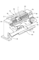
図1は、本発明の第1実施例に係るインクジェット記録装置の斜視概念図である。
In this embodiment, a description will be given using a serial type ink jet recording apparatus as the ink jet recording apparatus. Further, the ink supply device constitutes a part of the ink jet recording device.
1. 1. Inkjet Recording Apparatus (1-1) Overall Configuration of Inkjet Recording Apparatus FIG. 1 is a schematic perspective view of an inkjet recording apparatus according to a first embodiment of the present invention.
図1に示すように、インクジェット記録装置50(以下、単に「記録装置」と称する)は、互いに向き合った2つの脚部55の上端部に跨るように固定されている。キャリッジ60には、ヘッド1(記録ヘッド)が搭載されている。
As shown in FIG. 1, the ink jet recording device 50 (hereinafter, simply referred to as a “recording device”) is fixed so as to straddle the upper ends of two
記録時は、搬送ロールホルダユニット52にセットされた記録媒体が記録位置まで給紙(搬送)される。キャリッジ60がキャリッジモータ(不図示)及びベルト伝動手段62より主走査方向B−Bに往復移動すると共にヘッド1の各ノズルからインク滴が吐出される。キャリッジ60が記録媒体の一方端まで移動すると、搬送ローラ51が所定量だけ記録媒体を副走査方向Aへ搬送する。
During recording, the recording medium set in the transport roll holder unit 52 is fed (transported) to the recording position. The
このように、記録動作と搬送動作とを交互に繰り返すことにより記録媒体全体に画像を形成する。画像形成後は、不図示のカッターによって記録媒体をカットし、カットされた記録媒体はスタッカ53に積載される。
Thus, an image is formed on the entire recording medium by alternately repeating the recording operation and the transport operation. After the image formation, the recording medium is cut by a cutter (not shown), and the cut recording medium is stacked on the
インク供給ユニット63には、黒、シアン、マゼンタ、イエローなどのインク色ごとに分かれたインクタンク5(第1のインクタンク)が具えられており、各色のインクが貯留されている。また、インクタンク5は、後述するリザーブタンク4(第2のインクタンク)を介して供給チューブ2(インク流路)に接続されている。また、供給チューブ(インク流路)2はキャリッジ60の往復移動の際の障碍物とならないように、チューブガイド61によって束ねられている。
The
ヘッド1の記録媒体に対向した面には、主走査方向B−Bと略直交した方向に複数のノズル列(不図示)が備られており、ノズル列単位で供給チューブ2(インク流路)と接続している。
A plurality of nozzle rows (not shown) are provided on a surface of the
回復ユニット70が主走査方向B−Bにおいて記録媒体の領域外で、かつヘッド1のノズル面に対向する位置に設けられている。回復ユニット70は、必要に応じてヘッド1の吐出口面からインク又は空気を吸引し、ノズルのクリーニングを行ったり、ヘッド内部に溜まった空気を強制的に吸引する吸引手段を備えている。
The
記録装置50の右側(図1を参照する)には操作パネル54が設けられており、ユーザーは記録装置50に対して指令を入力することができる。また、インクタンク5内のインクが空になった際に、ユーザーへ警告を出してインクタンク5の交換を促すこともできる。
An
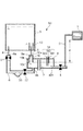
図2は、第1実施例のインクジェット記録装置のインク流路の概念図である。なお、本実施例では、1色分のインク流路を例として説明するが、複数色のインク流路についても同様である。 FIG. 2 is a conceptual diagram of the ink flow path of the ink jet recording apparatus according to the first embodiment. In the present embodiment, an ink channel for one color will be described as an example, but the same applies to ink channels for a plurality of colors.
図2に示すように、本実施例の記録装置50は、主にインクを収容するインクタンク5と、インクタンク5から供給されるインクを収容するリザーブタンク4と、リザーブタンク4から供給されるインクを用いて記録を行うヘッド1を備える。
As illustrated in FIG. 2, the
また、リザーブタンク4は、インクタンク5の下方に配置されている。インクタンク5とリザーブタンク4の間には、インクタンク5からリザーブタンク4へインクを供給するインク供給路6と、リザーブタンク4からインクタンク5へ空気を導入する空気導入路10とが備えられている。
Further, the
なお、リザーブタンク4は大気と連通する大気連通部7を備え、大気開放されている。一方、インクタンク5は大気連通部を有さず、大気開放されていない。また、インクタンク5は、リザーブタンク4(装置本体)に対して着脱可能である。
The
インクタンク5は、内部にインクを貯留する内部空間を有し、底部には2カ所のジョイント部が設けられている。このジョイント部には、後述する第1の中空管8と第2の中空管9が挿入可能である。また、インクタンク5内に挿入された第2の中空管9の周囲には、第2の中空管9を囲むようにインクタンク5の底部(底面)から立設された筒状の立ち壁42が配置されている。
The
インク供給路6の一端6aが第1の中空管8に接続され、他端6bがリザーブタンク4の底部に接続されている。
One
一方、空気導入路10の一端10aが第2の中空管9に接続され、他端10bがリザーブタンク4の上部(上面)に接続されている。また、空気導入路10の他端10bは、リザーブタンク4の上面からリザーブタンク4内に挿入された状態で配置されており、開口10cを備えている。
On the other hand, one
即ち、リザーブタンク4において、インク供給路6の開口(他端6b)位置が空気導入路10の開口10c位置よりも下方に配置されている。このため、水頭差により、インク供給路6(および第1の中空管8)を通じてインクタンク5からリザーブタンク4へインクが供給された際、空気導入路10(および第2の中空管9)を通じてリザーブタンク4からインクタンク5へ空気が導入される。
That is, in the
一方、リザーブタンク4内の液面の上昇によって開口10cが封止されたとき、リザーブタンク4からインクタンク5への空気の移動が停止され、インクタンク5からリザーブタンク4へのインクの供給も停止される。
On the other hand, when the
このように、リザーブタンク4内のインクが消費されて液面が下がると、空気導入路10を通じて空気がインクタンク5へ導入されると共に、リザーブタンク4へインクが自動的に供給される(バードフィード供給方式)。なお、インクタンク5内のインクが無くなるまでは、リザーブタンク4内のインクの液面は空気導入路10の開口10cと略同じ高さに位置される。
As described above, when the ink in the
リザーブタンク4内には、金属製の中実管341〜343が電極34として設けられている。第1の中実管341の下端は空気導入路10の開口10cよりも若干下方(本実施例では約4mm下)に設けられている。これにより、リザーブタンク4の満タン状態を確実に検出することができる。また、第2の中実管342と第3の中実管343は略同じ長さを有し、それぞれの下端は第1の中実管341の下端よりも下方に位置し且つリザーブタンク4からヘッド1へのインク流出口401よりも上方に位置している。
In the
これにより、第1の中実管341と第3の中実管343の間に微弱な電圧を印加した場合、リザーブタンク4内のインクが満タン状態のとき、インクを通じて電極間に電流が流れて2つの電極間の抵抗値が低くなる。このように、電極間の抵抗値変化に基づき、リザーブタンク4が「満タン状態」であるか否かを検知することができる。
Accordingly, when a weak voltage is applied between the first
同様に、第2の中実管342と第3の中実管343の間に微弱な電圧を印加した場合、リザーブタンク4内のインクが電極34の下端よりも低下したとき、2つの電極間に電流が流れず抵抗値が上がる。このように、電極間の抵抗値変化に基づき、リザーブタンク4が「空状態」であるか否かを検知することができる。
Similarly, when a weak voltage is applied between the second
なお、インクタンク5内にインクがある限り、バードフィード供給方式に基づきリザーブタンク4内は「満タン状態」とすることができる。従って、電極34によってリザーブタンク4内のインクが「満タン状態」ではないと検知された場合、インクタンク5内のインクが空状態になったと推定できる。即ち、電極34はインクタンク5の「空状態」を検知することもできる。
In addition, as long as there is ink in the
なお、本実施例では、インク流出口401は、リザーブタンク4の側面において最も低い位置に設けられている。また、リザーブタンク4と供給チューブ2の間に開閉弁3が設けられている。開閉弁3を設けることにより、後述する「ヘッド内の空気の除去およびヘッド内のインクの充填」をスムーズに行うことができる。
In this embodiment, the
なお、本実施例では、後述するインク撹拌機構と同じ駆動源によって開閉弁3が駆動されるが、開閉弁3を別の駆動源で駆動してもよい。また、複数色のインク流路内の開閉弁を同時に駆動されるように構成しても良い。
In this embodiment, the on-off
また、本実施例では、リザーブタンク4内のインクの液面とヘッド1の吐出口面との水頭差H(図2を参照する)によってヘッド1内のインクの負圧が維持されている。なお、本実施例ではこの水頭差Hは約80mmである。
Further, in the present embodiment, the negative pressure of the ink in the
なお、ヘッド1内部に空気が溜まっている場合、強制的にヘッド内の空気を除去する必要がある。ヘッド内の空気の除去方法として、開閉弁3を閉じた状態で、回復ユニット70(図1)によってヘッド1を吸引する。
When air is accumulated inside the
具体的には、ヘッド1の吐出口面にキャップ(図示しない)を密着させ、ポンプ(図示しない)を駆動して空気を吸引する。所定時間(本実施例では約25秒)の吸引を行った後、開閉弁3を開放させ、ヘッド内にインクが充填される。即ち、吸引後に開閉弁3を開放させることにより、ヘッド内の負圧によってリザーブタンク4からヘッド1へ所定量のインクが吸い込まれる。これにより、ヘッド内にインクが充填される。なお、ヘッド1内のインクが消費されるに連れ、インクタンク5、リザーブタンク4の順に再びヘッド1へインクが供給される。
Specifically, a cap (not shown) is brought into close contact with the ejection port surface of the
(1−2)インクジェット記録装置の制御機構
図3は、第1実施例のインクジェット記録装置の制御機構を示すブロック図である。
(1-2) Control Mechanism of Inkjet Printing Apparatus FIG. 3 is a block diagram showing a control mechanism of the inkjet printing apparatus of the first embodiment.
図3に示すように、本実施例の記録装置50は、主に記録装置を制御するCPU11、ユーザーが操作するキーや情報を表示する操作パネルを含むユーザーインターフェース12を備えている。また、記録装置50は、制御ソフトウエアを内蔵するROM13、制御ソフトウエアを動作させる際に一時的に使用するRAM14を備えている。更に、記録装置50は、駆動部I/O15、駆動部分16、インク量を検知する検知手段17、インクタンクの着脱を検出するインクタンク装着センサ18を備えている。
As shown in FIG. 3, the
なお、本実施例では、検知手段17は、電極34と電極34に繋ぐ電気回路を備え、電極34の電圧値からリザーブタンク4内の液面情報を検知している。また、検知手段17は、インクタンク5内のインク量を検知する構成を有してもよい。
In the present embodiment, the detecting
インクタンク装着センサ18は、インクタンク5に取り付けられたEEPROM20の読み値で着脱状態を判定している。また、インクタンク装着センサ18を用いてEEPROM20の内容(記録情報)の読み書きを行う。つまり、インクを使用する度に、EEPROM20にインクタンク5の残量が記録され、インクタンク5の残量管理が行われている。
The ink
2.インク撹拌機構
(2−1)インク撹拌機構の構成
以下、本実施例のインク撹拌機構の構成について説明する。
2. Ink stirring mechanism (2-1) Configuration of ink stirring mechanism Hereinafter, the configuration of the ink stirring mechanism of the present embodiment will be described.
インク撹拌機構は、インク供給路6に設けられ、開閉可能な第1開閉弁31(第1開閉部)および第2開閉弁32(第2開閉部)と、可撓部33(容積変化部)とを備える。
The ink stirring mechanism is provided in the
具体的には、第1開閉弁31がインクタンク5と可撓部33の間に配置され、第2開閉弁32がリザーブタンク4と可撓部33の間に配置されている。第1開閉弁31、第2開閉弁32は、それぞれ開状態と閉状態とに切り替わることによってインク供給路6を開閉することができる。可撓部33は、可撓性を有し内部容積が変化可能な部材で構成されている。可撓部33を変形させて、内部容積を変化させることにより、可撓部33にインクの出入ができる。なお、本実施例では、第1開閉弁31、第2開閉弁32、可撓部33は、共通の駆動機構(不図示)により駆動されている。
Specifically, the first on-off
本実施例では、可撓部33は、インク供給路6において、重力方向の最下部に設けられている。これにより可撓部33内に気泡の混入が少なく、効率的にインクを移動させることができる。また、本実施例では、可撓部33の容積可変量は約0.7〜1mlに設定されている。なお、可撓部33の配置や内部容積などを適宜に変更して実施することも可能である。
In the present embodiment, the
(2−2)インク撹拌機構の制御
本実施例では、インク撹拌機構の撹拌制御は、インクタンク5に対する撹拌動作(第1の撹拌動作)とリザーブタンク4に対する撹拌動作(第2の撹拌動作)を行う。
(2-2) Control of the ink stirring mechanism In the present embodiment, the stirring control of the ink stirring mechanism is performed by the stirring operation for the ink tank 5 (first stirring operation) and the stirring operation for the reserve tank 4 (second stirring operation). I do.
また、本実施例では、インク撹拌機構の撹拌制御は、前回の撹拌が行ってから所定時間を経過した場合と、インクタンク5が交換された場合に実行される。なお、撹拌を行う時間は、経過時間によって変更することもできる。例えば、経過時間が長くなるほど、撹拌時間を長く設定することができる。
Further, in the present embodiment, the stirring control of the ink stirring mechanism is executed when a predetermined time has elapsed since the previous stirring was performed and when the
以下、本実施例のインク撹拌機構の制御(撹拌動作)について詳細に説明する。 Hereinafter, control (stirring operation) of the ink stirring mechanism of the present embodiment will be described in detail.
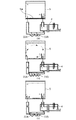
図4(a)〜(c)は、本実施例のインク撹拌制御のフローチャートである。図5(a)〜(c)は、本実施例のリザーブタンク内のインク撹拌動作を示す概念図である。また、図6(a)〜(c)は、本実施例のインクタンク内のインク撹拌動作を示す概念図である。 FIGS. 4A to 4C are flowcharts of the ink stirring control according to the present embodiment. FIGS. 5A to 5C are conceptual diagrams illustrating the ink stirring operation in the reserve tank according to the present embodiment. FIGS. 6A to 6C are conceptual diagrams illustrating an ink stirring operation in the ink tank according to the present embodiment.
図5(a)に示すように、インクタンク5及びリザーブタンク4を放置して時間が経過すると、インクタンク5およびリザーブタンク4内にそれぞれ沈降した高濃度インク層5a、4aが発生する。
As shown in FIG. 5A, when the
このような撹拌動作が必要な場合では、図4(a)に示すように、まず、全色のインクタンク5が「空状態」になっているかどうかを判定する(S201)。なお、前述したように、インクタンク5の「空状態」の判定は、リザーブタンク4が「満タン状態」でないことによって推定される。即ち、リザーブタンク4内の電極34の電気信号に基づき、検知手段17が「満タン状態」でない(即ち、OFF信号)と検知したときに、インクタンク5が「空状態」であると判定される。
When such a stirring operation is necessary, as shown in FIG. 4A, first, it is determined whether or not the
次に、複数色のインクのうち、いずれか1色のインクタンク5が「空状態」ではないと判定された場合、リザーブタンク4の撹拌動作(第2の撹拌動作)を行う(S202)。そして、リザーブタンク4の撹拌動作が完了した後に、インクタンク5の撹拌動作(第1の撹拌動作)を行う(S203)。言い換えれば、全てのインクタンク5が「空状態」でない限り、第1の撹拌動作(インクタンク5の撹拌)の前に、第2の撹拌動作(リザーブタンク4の撹拌)を行うことができる。
Next, when it is determined that the
これにより、リザーブタンク4の撹拌動作が終了した時点で記録動作を早期に開始させることができ、ダウンタイムの削減に寄与する。なお、記録動作をしながらインクタンク5の撹拌動作を行ってもよい。
Thus, the recording operation can be started early when the stirring operation of the
一方、複数色のインク流路内の全てのインクタンクが空状態になっている場合(即ち、リザーブタンク4が「満タン状態」ではなく、OFF信号の場合)、リザーブタンク4の撹拌動作のみ行う(S204)。
On the other hand, when all the ink tanks in the ink flow paths of a plurality of colors are empty (that is, when the
以下、リザーブタンク4の撹拌制御の詳細フローチャートを図4(b)に示し、インクタンク5の撹拌制御の詳細フローチャートを図4(c)に示す。
Hereinafter, a detailed flowchart of the stirring control of the
(A)リザーブタンクの撹拌制御について
図4(b)に示すように、リザーブタンク4の撹拌制御の方法として、まず、第1開閉弁31を閉じる(S301)。(図5(a)に示す状態)
そして、可撓部33を(容積)縮小変形させる(S302)。(図5(b)に示す状態)
図5(b)に示すように、第1開閉弁31を閉じた状態で可撓部33を縮小変形させると、インク供給路6からインクタンク5側へインクが押し出されず、可撓部33内の変化量分のインクがリザーブタンク4側へ押し出される。
(A) Stirring Control of Reserve Tank As shown in FIG. 4B, as a method of stirring control of the
Then, the
As shown in FIG. 5B, when the
これにより、リザーブタンク4内にインクの大きな流れが生じて、沈降した濃いインク層4aが巻き上げられて撹拌される。
As a result, a large flow of ink occurs in the
その後、図5(c)に示すように、可撓部33を(容積)拡大変形させる(S302)と、リザーブタンク4内のインクが可撓部33の変化量分だけインク供給路6に引き込まれる。
Thereafter, as shown in FIG. 5C, when the
また、上記の様に、可撓部33の容積変化動作を複数(N)回実施する(S303)。
Further, as described above, the volume changing operation of the
このように、図5の(b)と(c)の状態を繰り返し実行させることにより、リザーブタンク4内のインクを効果的に撹拌することができ、リザーブタンク4内のインク濃度を均一化にすることができる。
In this way, by repeatedly executing the states of FIGS. 5B and 5C, the ink in the
なお、経過(放置)期間によって決められた回数(N)分の容積変化動作が終わると、第1開閉弁31を開放させ(S304)、リザーブタンク4の撹拌制御が終了する。
When the volume changing operation for the number of times (N) determined by the elapsed (leaving) period is completed, the first on-off
(B)インクタンクの撹拌制御について
図4(c)に示すように、インクタンク5の撹拌制御の方法として、まず、第2開閉弁32を閉じる(S401)。(図6(a)に示す状態)
そして、可撓部33を(容積)縮小変形させる(S402)。(図6(b)に示す状態)
図6(b)に示すように、第2開閉弁32が閉じた状態で可撓部33を縮小変形させると、インク供給路6からリザーブタンク4側へインクが押し出さられず、可撓部33内の変化量分のインクがインクタンク5側へ押し出される。
(B) Stirring Control of Ink Tank As shown in FIG. 4C, as a method of stirring control of the
Then, the
As shown in FIG. 6B, when the
これにより、インクタンク5にインクの大きな流れが生じて、沈降した濃いインク層5aが巻き上げられて撹拌される。
As a result, a large flow of ink occurs in the
その後、図6(c)に示すように、可撓部33を(容積)拡大変形させる(S402)と、インクタンク5内のインクが可撓部33の変化量分だけインク供給路6に引き込まれる。
After that, as shown in FIG. 6C, when the
また、上記の様に、可撓部33の容積変化動作を複数(N)回に実行する(S403)。
Further, as described above, the volume changing operation of the
このように、図6の(b)と(c)の状態を繰り返し実行させることにより、インクタンク5内のインクを効果的に撹拌することができ、インクタンク5内のインク濃度を均一化にすることができる。
In this way, by repeatedly executing the states of FIGS. 6B and 6C, the ink in the
なお、経過(放置)期間によって決められた回数(N)分の容積変化動作が終わると、第1開閉弁31を開放させ(S404)、インクタンク5の撹拌制御が終了する。
When the volume changing operation for the number of times (N) determined by the elapsed (leaving) period is completed, the first on-off
なお、インクタンク5にインクが押し出されることにより、内圧の増加によってインクタンク5から空気導入路10を介してリザーブタンク4へ一部のインクが押し出されることがある。ここで、前述したように、インクタンク5の底部には、第2の中空管9を周方向に囲む筒状の立ち壁42が設けられているため、立ち壁42の外側の濃いインク層5a部分が第2の中空管9(空気導入路10)を通じてリザーブタンク4へ流入されにくい。なお、立ち壁42の内側の濃いインク層5aの部分は少量のため、リザーブタンク4に流出してもリザーブタンク4の濃度には大きな影響がない。
When the ink is pushed out to the
(2−3)その他
以下、インクタンク5の撹拌後のリザーブタンク4へのインク供給(補給)について説明する。
前述したように、リザーブタンク4のインク撹拌が終了した後に、記録動作をしながらインクタンク5の撹拌動作を行うことができる。この場合、リザーブタンク4内のインクが消費されるため、インクタンク5のインク撹拌動作が終了した後に、インクタンク5からリザーブタンク4へインクを供給(補給)する必要がある。
(2-3) Others Hereinafter, ink supply (supplement) to the
As described above, after the ink stirring of the
インクの供給方法として、第1開閉弁31と第2開閉弁32を開け、空気導入路10を介してインクタンク5へ空気が導入されると共に、インクタンク5からリザーブタンク4へインクが自動的に供給(補給)される。(バードフィード供給方式)
なお、バードフィード供給方式のインク供給量(供給速度)が記録動作に使用されるインク使用量(使用速度)以上である必要がある。本実施例では、インク供給量(供給速度)は、リザーブタンク4内のインク液面(即ち、空気導入路の下端の開口の端面(10c)の高さ位置)と第2の中空管9の下端面9a(図2を参照する)との「高低差(水頭差)」によって決定される。この高低差は、インク使用量に応じて、適宜に設定することが可能であるが、本実施例では、この高低差を約20mmとして設定している。
As a method of supplying ink, the first opening / closing
Note that the ink supply amount (supply speed) of the bird feed supply method needs to be equal to or more than the ink consumption amount (use speed) used for the recording operation. In the present embodiment, the ink supply amount (supply speed) depends on the ink liquid level in the reserve tank 4 (that is, the height position of the end face (10c) of the opening at the lower end of the air introduction path) and the second
次に、撹拌時間(回数)について説明する。 Next, the stirring time (number of times) will be described.
撹拌時間(又は回数)は、放置期間、環境温度、インク種類などに応じて適宜に設定することができる。例えば、本実施例では、撹拌時間(回数)が放置期間に応じて3つに設定される。 The stirring time (or the number of times) can be appropriately set according to the leaving period, the environmental temperature, the type of ink, and the like. For example, in this embodiment, the stirring time (number of times) is set to three according to the idle period.
具体的には、本実施例では、放置期間が10日以内であれば、リザーブタンクに対して約15秒、インクタンクに対して約30秒の撹拌動作が実行される。一方、放置期間が10日以上かつ20日未満であれば、リザーブタンクに対して約30秒、インクタンクに対して約1分30秒の撹拌動作が実行される。そして、放置期間が20日以上であれば、リザーブタンクに対して約1分、インクタンクに対して約3分の撹拌動作が実行される。なお、本実施例では、可撓部33の容積変化は約1秒で1回の縮小変形動作と1回の拡大変形動作を行う(即ち、1Hzで可撓部を変形動作させている)。
Specifically, in this embodiment, if the leaving period is within 10 days, the stirring operation is performed for about 15 seconds for the reserve tank and for about 30 seconds for the ink tank. On the other hand, if the idle period is 10 days or more and less than 20 days, the stirring operation is performed for about 30 seconds for the reserve tank and for about 1 minute and 30 seconds for the ink tank. If the leaving period is 20 days or more, the stirring operation is performed for about 1 minute for the reserve tank and about 3 minutes for the ink tank. In the present embodiment, the volume change of the
次に、インクタンクの着脱動作後の撹拌動作について説明する。
インクタンク5が装着された後に、リザーブタンク4へのインクの充填が完了すると、インクタンク5に対して撹拌動作を行うことができる。なお、インクタンク5の装着状態(着脱)は、前述した着脱センサ18(図3を参照する)によって検知される。また、インクタンク5の撹拌動作は、前述したインクタンクの撹拌動作(図4(c)および図6を参照する)と同様である。また、複数色のインクタンクの撹拌動作を同時に行っても良く、個別に行っても良い。
Next, the stirring operation after the ink tank attaching / detaching operation will be described.
After filling of the
このように、本発明の第1実施例では、インク撹拌機構は、インク供給路から第2のインクタンクへインクが移動できない状態とした後に、インク供給路と第1のインクタンクの間でインクを移動させて撹拌する第1の撹拌動作を行う。また、インク供給路から第1のインクタンクへインクが移動できない状態とした後に、インク供給路と第2のインクタンクの間でインクを移動させて撹拌する第2の撹拌動作を行う。 As described above, in the first embodiment of the present invention, the ink agitating mechanism sets the state in which ink cannot move from the ink supply path to the second ink tank, and then sets the ink between the ink supply path and the first ink tank. Is carried out to perform a first stirring operation for stirring. After the ink cannot be moved from the ink supply path to the first ink tank, a second stirring operation of moving and stirring the ink between the ink supply path and the second ink tank is performed.
これにより、第1、第2のインクタンクをそれぞれ独立して撹拌させることにより、効率的に第1、第2のインクタンク内のインク濃度を均一化にすることができる。 This allows the first and second ink tanks to be stirred independently of each other, so that the ink concentrations in the first and second ink tanks can be efficiently made uniform.
また、本実施例では、可撓部の内部容積の最大変化量は、インク供給路の容積よりも大きく設定することができる。これにより、より効率的にインクを撹拌することができる。 Further, in this embodiment, the maximum change amount of the internal volume of the flexible portion can be set to be larger than the volume of the ink supply path. Thereby, the ink can be stirred more efficiently.
また、本実施例では、インク撹拌機構は、第1の撹拌動作の前に、第2の撹拌動作を行うこともできる。これにより、リザーブタンク4の撹拌が完了した時点で記録動作を開始することができ、ダウンタイムの削減に有利である。
Further, in the present embodiment, the ink stirring mechanism can perform the second stirring operation before the first stirring operation. Thus, the recording operation can be started at the time when the stirring of the
また、本実施例では、第1のインクタンクと第2のインクタンクの容量が異なるため、それぞれに応じて、第1の撹拌動作と第2の撹拌動作を異なる動作とすることができる。これにより、より効率的にインクの撹拌動作を行うことができる。 Further, in the present embodiment, since the capacities of the first ink tank and the second ink tank are different, the first agitating operation and the second agitating operation can be different depending on each. Thereby, the stirring operation of the ink can be performed more efficiently.
また、リザーブタンク4の撹拌動作(第2の撹拌動作)が終了するまでに、既に記録装置50が記録指令を受信した場合、リザーブタンク4の撹拌動作が終了した後に、すぐに記録動作を開始することが可能である。即ち、記録動作が行われている間に、インクタンク5の撹拌動作(第1の撹拌動作)を開始してもよい。若しくは、記録動作と第1の撹拌動作を同時進行しても良い。言い換えれば、記録動作をしながらインクタンク5の撹拌動作を行うこともできる。
If the
また、本実施例では、第1の中空管8と第2の中空管9は共に金属針で構成されているが、それぞれをインク供給路6と空気導入路10の一部として形成してもよい。即ち、インク供給路6の一端をインクタンク5の底部に接続し、他端がリザーブタンクの底部に接続してもよい。また、空気導入路10の一端をインクタンク5の底部に接続し、他端をリザーブタンク4の上部に接続してもよい。
In the present embodiment, the first
また、本実施例では、検知手段17は電極34を用いてリザーブタンク4の残量検知(即ち、「満タン状態」及び「空状態」の検知)を行っているが、電極の他に、別のセンサを採用してもよい。例えば、フロート式や光学式等の他のセンサを採用してもよい。
Further, in the present embodiment, the detecting
また、本実施例では、インクタンク5の「空状態」の検知を、リザーブタンク4の「満タン状態」を検知するセンサによって間接的に行っているが、インクタンク5に専用のセンサを設けても良い。
Further, in the present embodiment, the detection of the “empty state” of the
また、本実施例では、リザーブタンク4の空状態の検知を電極34による方式で行っている。なお、リザーブタンク4の満タン位置(状態)の検知のみを電極34で行い、満タン位置を下まわったことを検知した後にヘッド1からの吐出数をカウントするドットカウント方式の検知手段を採用してもよい。
In this embodiment, the detection of the empty state of the
また、本実施例では、ヘッド1へのインク供給を水頭差方式で行っているが、リザーブタンク4とヘッド1の間にポンプ(図示しない)を設け、リザーブタンク4からヘッド1側へインクを加圧して送り込むようにしてもよい。
In this embodiment, the ink supply to the
また、本実施例では、開閉部が開閉弁で構成されているが、開閉弁に限らず、開閉可能な構成であればよい。例えば、開閉部を、駆動停止時に流路を遮断可能なポンプで構成されてもよく、開状態と閉状態とに切換可能な可撓部で構成されてもよい。 Further, in the present embodiment, the opening / closing section is constituted by an opening / closing valve. For example, the opening / closing section may be configured by a pump that can shut off the flow path when driving is stopped, or may be configured by a flexible section that can be switched between an open state and a closed state.
(第2実施例)
以下、図7を用いて本発明の第2実施例のインクジェット記録装置について説明する。
図7は、本発明の第2実施例に係るインクジェット記録装置のインク流路概念図である。図7に示すように、本実施例では、インク撹拌機構は、インク供給路6に設けられた開閉弁31A(開閉部)と、第1の可撓部33Aと、第2の可撓部33Bとを備える。
(Second embodiment)
Hereinafter, an ink jet recording apparatus according to a second embodiment of the present invention will be described with reference to FIG.
FIG. 7 is a conceptual diagram of the ink flow path of the ink jet recording apparatus according to the second embodiment of the present invention. As shown in FIG. 7, in the present embodiment, the ink stirring mechanism includes an opening /
具体的には、第1の可撓部33Aは、開閉弁31Aとインクタンク5の間に配置される。第2の可撓部33Bは、開閉弁31Aとリザーブタンク4の間に配置されている。また、開閉弁31A、第1の可撓部33A、第2の可撓部33Bは、共通の駆動機構(不図示)により駆動されている。
Specifically, the first
インク撹拌機構は、開閉弁31Aを閉状態とした後に、第1の可撓部33Aの内部容積を変化させて第1の撹拌動作を行うことにより、独立してインクタンク5(第1のインクタンク)内のインクを撹拌することができる。
The ink stirring mechanism independently changes the internal volume of the first
また、開閉弁31Aが閉じた状態で、第2の可撓部33Bの内部容積を変化させて前記第2の撹拌動作を行うことにより、独立してリザーブタンク4(第2のインクタンク)内のインクを撹拌することができる。
In addition, by performing the second stirring operation by changing the internal volume of the second
このように、第2実施例は、第1実施例と同様に、第1、第2のインクタンクを夫々独立して撹拌させることにより、効率的に第1、第2のインクタンク内のインク濃度を均一化にすることができる。 As described above, in the second embodiment, similarly to the first embodiment, the ink in the first and second ink tanks is efficiently made by independently stirring the first and second ink tanks. The concentration can be made uniform.
(第3実施例)
以下、図8を用いて本発明の第3実施例のインクジェット記録装置について説明する。
図8は、本発明の第3実施例に係るインクジェット記録装置のインク流路概念図である。図8に示すように、本実施例では、インク撹拌機構は、インク供給路6に設けられた第1開閉弁31(第1開閉部)と、第2開閉弁32(第2開閉部)と、ポンプ35(供給手段)と、インク収容部36と、接続流路36Aと、を備える。
(Third embodiment)
Hereinafter, an ink jet recording apparatus according to a third embodiment of the present invention will be described with reference to FIG.
FIG. 8 is a conceptual diagram of the ink flow path of the ink jet recording apparatus according to the third embodiment of the present invention. As shown in FIG. 8, in the present embodiment, the ink stirring mechanism includes a first opening / closing valve 31 (first opening / closing section) provided in the
具体的には、インク収容部36は、接続流路36Aを通じてインク供給路6に接続されており、インク供給路6から流れるインクを一時的に収容可能なように構成されている。なお、インク収容部36は、可撓性を有し、内部容積が変化可能な部材で構成されている。
Specifically, the
ポンプ35は、接続流路36Aに設けられており、流路内のインクを正方向(第1方向)と逆方向(第1方向の逆方向である第2方向)に供給可能に構成されている。
The
インク撹拌機構は、第2開閉弁32を閉状態とした後に、供給手段35によって第1の撹拌動作を行うことにより、独立してインクタンク5(第1のインクタンク)内のインクを撹拌することができる。
また、第1開閉弁31を閉状態とした後に、供給手段35によって第2の撹拌動作を行うことにより、独立してリザーブタンク4(第2のインクタンク)内のインクを撹拌することができる。
The ink stirring mechanism independently stirs the ink in the ink tank 5 (first ink tank) by performing the first stirring operation by the
Further, after the first on-off
また、本実施例でも、撹拌時間(回数)が放置期間に応じて3つに設定できる。
具体的には、本実施例では、放置期間が10日以内であれば、リザーブタンクに対して約10秒、インクタンクに対して約20秒の撹拌動作が実行される。一方、放置期間が10日以上かつ20日未満であれば、リザーブタンクに対して約20秒、インクタンクに対して約1分の撹拌動作が実行される。そして、放置期間が20日以上であれば、リザーブタンクに対して約30秒、インクタンクに対して約2分の撹拌動作が実行される。なお、本実施例では、ポンプ35においてインクを流出/流入させる正逆の動作を約2〜3秒の間隔で制御している。
Also in this embodiment, the stirring time (number of times) can be set to three according to the idle period.
Specifically, in this embodiment, if the leaving period is within 10 days, the stirring operation is performed for about 10 seconds for the reserve tank and about 20 seconds for the ink tank. On the other hand, if the leaving period is 10 days or more and less than 20 days, the stirring operation is performed for about 20 seconds for the reserve tank and about 1 minute for the ink tank. If the leaving period is 20 days or more, the stirring operation is performed for about 30 seconds for the reserve tank and about 2 minutes for the ink tank. In this embodiment, the forward / reverse operation for causing the ink to flow out / in by the
このように、第3実施例は、第1実施例と同様に、第1、第2のインクタンクを夫々独立して撹拌させることにより、効率的に第1、第2のインクタンク内のインク濃度を均一化にすることができる。 As described above, in the third embodiment, similarly to the first embodiment, the ink in the first and second ink tanks is efficiently circulated by independently stirring the first and second ink tanks. The concentration can be made uniform.
なお、本実施例のインク収容部36は、インク収容部36の容積変化によって、インクタンク5またはリザーブタンク4にインクを流入または流出させるように構成されてもよい。
In addition, the
また、インクの流入/流出量がインク収容部36の可変容積によって決められるが、本実施例では、例えば、インク収容部36の容積可変量を5mLとして設定することができる。この場合、第1実施例の可撓部33の容積可変量(0.7〜1mL)に比べて、本実施例では、1回の変形動作によって、移動できるインク量が多くなり、より顕著な撹拌効果が期待できる。また、撹拌時間の短縮も期待できる。
Further, although the inflow / outflow amount of the ink is determined by the variable volume of the
(第4実施例)
以下、図9〜図11を用いて本発明の第4実施例のインクジェット記録装置について説明する。
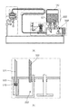
図9は、本発明の第4実施例に係るインクジェット記録装置のインク流路概念図である。図10(a)〜(c)は、第4実施例のインクタンク内のインク撹拌動作を示す概念図である。図11(a)〜(c)は、第4実施例のリザーブタンク内のインク撹拌動作を示す概念図である。
(Fourth embodiment)
Hereinafter, an ink jet recording apparatus according to a fourth embodiment of the present invention will be described with reference to FIGS.
FIG. 9 is a conceptual diagram of the ink flow path of the ink jet recording apparatus according to the fourth embodiment of the present invention. FIGS. 10A to 10C are conceptual diagrams showing the ink stirring operation in the ink tank of the fourth embodiment. FIGS. 11A to 11C are conceptual diagrams showing the ink stirring operation in the reserve tank of the fourth embodiment.
図9に示すように、本実施例では、インク撹拌機構は、インク供給路6に設けられた第1の可撓部33Aと、第2の可撓部33Bとを備える。
As shown in FIG. 9, in the present embodiment, the ink stirring mechanism includes a first
第1の可撓部33Aおよび第2の可撓部33Bは、第1実施例の可撓部33と同様な構成を有し、直列的にインク供給路6に配置されている。また、第1、第2の可撓部33A、33Bの容積可変量も第1実施例の可撓部33と同様に、0.7〜1mlに設定される。
The first
図10(a)〜(c)に示すように、インク撹拌機構は、第2の可撓部33Bによってインク供給路6を閉状態とした後に、第1の可撓部33Aの内部容積を変化させて第1の撹拌動作を行う。これにより、独立してインクタンク5(第1のインクタンク)内のインクを撹拌することができる。
As shown in FIGS. 10A to 10C, the ink stirring mechanism changes the internal volume of the first
また、図11(a)〜(c)に示すように、第1の可撓部33Aによってインク供給路6を閉状態とした後に、第2の可撓部33Bの内部容積を変化させて第2の撹拌動作を行う。これにより、独立してリザーブタンク4(第2のインクタンク)内のインクを撹拌することができる。
Further, as shown in FIGS. 11A to 11C, after the
本実施例では、第1の撹拌動作の後に、第2の撹拌動作を行う制御の例を示したが、第1実施例と同様に、第1の撹拌動作の前に、第2の撹拌動作を行っても良い。 In the present embodiment, an example of control in which the second stirring operation is performed after the first stirring operation has been described. However, similar to the first embodiment, the second stirring operation is performed before the first stirring operation. May be performed.
以上のように、第1〜第4実施例に説明した本発明によれば、インク撹拌機構によって第1、第2のインクタンクを夫々独立して撹拌させることにより、効率的に第1、第2のインクタンク内のインク濃度を均一化することができる。 As described above, according to the present invention described in the first to fourth embodiments, the first and second ink tanks are independently agitated by the ink agitating mechanism, so that the first and second ink tanks are efficiently provided. The ink concentration in the second ink tank can be made uniform.
即ち、撹拌の際における第1、第2のインクタンクの互いの影響を取り除くことができ、高い撹拌効率を得ることができる。 That is, the mutual influence of the first and second ink tanks at the time of stirring can be eliminated, and high stirring efficiency can be obtained.
また、第1のインクタンクを撹拌する際、第2のインクタンクへの圧力の伝達を遮断することによって圧力の分散が無くなる。インク撹拌機構の撹拌動作によって発生する圧力が単一のインクタンクのインクに集中することにより、撹拌効果が高まる。その結果、第2のインクタンクのサイズを大きくすることなく、効率的に第1、第2のインクタンク内のインクを撹拌することができる。よって、インク供給装置またはインクジェット記録装置のダウンタイムを抑制しつつインク撹拌効率が向上し、撹拌時間を短縮できる。 Further, when the first ink tank is agitated, the transmission of the pressure to the second ink tank is cut off, thereby eliminating the dispersion of the pressure. When the pressure generated by the stirring operation of the ink stirring mechanism is concentrated on the ink in the single ink tank, the stirring effect is enhanced. As a result, the ink in the first and second ink tanks can be efficiently agitated without increasing the size of the second ink tank. Therefore, the ink stirring efficiency is improved while the downtime of the ink supply device or the inkjet recording device is suppressed, and the stirring time can be reduced.
また、本発明によれば、リザーブタンクのサイズによらず、効率的にインクタンク及びリザーブタンク内のインクを撹拌することができる。また、インク撹拌機構の容量や作動速度を上げれば、より大型のインクタンクまたはリザーブタンクにも対応できる。 Further, according to the present invention, the ink in the ink tank and the ink in the reserve tank can be efficiently stirred regardless of the size of the reserve tank. Further, if the capacity and operation speed of the ink stirring mechanism are increased, it is possible to cope with larger ink tanks or reserve tanks.
また、本発明によれば、リザーブタンクの撹拌動作後に記録動作をしながらインクタンク内のインクを撹拌することができ、ダウンタイムを更に削減できる。そして、本発明のインクジェット記録装置では、ピストン機構を有さない為、摺動部の摺動によって発生するゴミがなく、インク品質の低下を防ぐことができる。 Further, according to the present invention, it is possible to stir the ink in the ink tank while performing the recording operation after the stirring operation of the reserve tank, so that downtime can be further reduced. In addition, since the ink jet recording apparatus of the present invention does not have a piston mechanism, there is no dust generated by sliding of the sliding portion, and it is possible to prevent a decrease in ink quality.
(第5実施例)
以下、図13〜図16を参照して本発明の第5実施例について説明する。
(Fifth embodiment)
Hereinafter, a fifth embodiment of the present invention will be described with reference to FIGS.
なお、本実施例では、インクジェット記録装置として、シリアル型のインクジェット記録装置を用いて説明する。また、インク供給装置は、インクジェット記録装置の一部を構成するものである。 In this embodiment, a description will be given using a serial type ink jet recording apparatus as the ink jet recording apparatus. Further, the ink supply device constitutes a part of the ink jet recording device.
1.インクジェット記録装置
(1−1)インクジェット記録装置の全体構成
本発明の第5実施例に係るインクジェット記録装置の基本構成は、基本的に第1実施例と同様である(図1を参照する)。
1. Inkjet Printing Apparatus (1-1) Overall Configuration of Inkjet Printing Apparatus The basic configuration of the inkjet printing apparatus according to the fifth embodiment of the present invention is basically the same as that of the first embodiment (see FIG. 1).
即ち、図1に示すように、本実施例のインクジェット記録装置50(以下、単に「記録装置」と称する)は、互いに向き合った2つの脚部55の上端部に跨るように固定されている。キャリッジ60には、ヘッド1(記録ヘッド)が搭載されている。
That is, as shown in FIG. 1, the ink
記録時は、搬送ロールホルダユニット52にセットされた記録媒体が記録位置まで給紙(搬送)される。キャリッジ60がキャリッジモータ(不図示)及びベルト伝動手段62より主走査方向B−Bに往復移動すると共にヘッド1の各ノズルからインク滴が吐出される。キャリッジ60が記録媒体の一方端まで移動すると、搬送ローラ51が所定量だけ記録媒体を副走査方向Aへ搬送する。
During recording, the recording medium set in the transport roll holder unit 52 is fed (transported) to the recording position. The
このように、記録動作と搬送動作とを交互に繰り返すことにより記録媒体全体に画像が形成される。画像形成後は、不図示のカッターによって記録媒体をカットし、カットされた記録媒体はスタッカ53に積載される。
Thus, an image is formed on the entire recording medium by alternately repeating the recording operation and the transport operation. After the image formation, the recording medium is cut by a cutter (not shown), and the cut recording medium is stacked on the
インク供給ユニット63には、黒、シアン、マゼンタ、イエローなどのインク色ごとに分かれたインクタンク5(第1のインクタンク)が具えられており、各色のインクが貯留されている。また、インクタンク5は、後述するリザーブタンク4(第2のインクタンク)を介して供給チューブ2(インク流路)に接続されている。また、供給チューブ(インク流路)2はキャリッジ60の往復移動の際の障碍物とならないように、チューブガイド61によって束ねられている。
The
ヘッド1の記録媒体に対向した面には、主走査方向B−Bと略直交した方向に複数のノズル列(不図示)が備られており、ノズル列単位で供給チューブ2(インク流路)と接続している。
A plurality of nozzle rows (not shown) are provided on a surface of the
回復ユニット70が主走査方向B−Bにおいて記録媒体の領域外で、かつヘッド1のノズル面に対向する位置に設けられている。回復ユニット70は、必要に応じてヘッド1の吐出口面からインク又は空気を吸引し、ノズルのクリーニングを行ったり、ヘッド内部に溜まった空気を強制的に吸引する吸引手段を備えている。
The
記録装置50の右側(図1を参照する)には操作パネル54が設けられており、ユーザーは記録装置50に対して指令を入力することができる。また、操作パネル54は、インクタンク5内のインクが空になった際に、インクタンク5の交換を促す警告を表示することもできる。
An
図13は、第5実施例のインクジェット記録装置のインク流路の概念図である。なお、本実施例では、1色分のインク流路を例として説明するが、複数色のインク流路についても同様である。 FIG. 13 is a conceptual diagram of the ink flow path of the ink jet recording apparatus according to the fifth embodiment. In the present embodiment, an ink channel for one color will be described as an example, but the same applies to ink channels for a plurality of colors.
図13に示すように、本実施例の記録装置50は、主にインクを収容するインクタンク5と、インクタンク5から供給されるインクを収容するリザーブタンク4と、リザーブタンク4から供給されるインクを用いて記録動作を行うヘッド1を備える。
As shown in FIG. 13, the
また、リザーブタンク4は、インクタンク5の下方に配置されている。インクタンク5とリザーブタンク4の間には、インクタンク5からリザーブタンク4へインクを供給するインク供給路6(第1の流路)と、リザーブタンク4からインクタンク5へ空気を導入する空気導入路10(第2の流路)とが備えられている。
Further, the
なお、リザーブタンク4は大気と連通する大気連通部7を備え、大気開放されている。一方、インクタンク5は大気連通部を有さず、大気開放されていない。また、インクタンク5は、リザーブタンク4(装置本体)に対して着脱可能である。
The
インクタンク5は、内部にインクを貯留する内部空間を有し、底部には2カ所のジョイント部が設けられている。このジョイント部には、後述する第1の中空管8(第1の流路)と第2の中空管9(第2の流路)が挿入可能である。また、インクタンク5内に挿入された第2の中空管9の周囲には、第2の中空管9を囲むようにインクタンク5の底部(底面)から立設された筒状の立ち壁42が配置されている。
The
インク供給路6の一端6aが第1の中空管8に接続され、他端6bがリザーブタンク4の底部に接続されている。即ち、インク供給路6は、他端6bにおいてリザーブタンク内に開口する開口6c(第1開口部)を備えている。なお、インク供給路6と第1の中空管8とで本発明の第1の流路が構成されている。
One
一方、空気導入路10の一端10aが第2の中空管9に接続され、他端10bがリザーブタンク4の上部(上面)に接続されている。また、空気導入路10の他端10bは、リザーブタンク4の上面からリザーブタンク4内に挿入された状態で配置されており、開口10c(第2開口部)を備えている。なお、空気導入路10と第2の中空管9とで本発明の第2の流路が構成されている。
On the other hand, one
即ち、リザーブタンク4において、インク供給路6の開口6c位置が空気導入路10の開口10c位置よりも下方に配置されている。言い換えれば、リザーブタンク4内において、第2の流路の第2開口部(開口10c)は、第1の流路の第1開口部(開口6c)よりも高い位置に配置される。
That is, in the
このため、水頭差により、インク供給路6(および第1の中空管8)を通じてインクタンク5からリザーブタンク4へインクが供給された際、空気導入路10(および第2の中空管9)を通じてリザーブタンク4からインクタンク5へ空気が導入される。
For this reason, when ink is supplied from the
一方、リザーブタンク4内の液面の上昇によって開口10cが封止されたとき、リザーブタンク4からインクタンク5への空気の移動が停止され、インクタンク5からリザーブタンク4へのインクの供給も停止される。
On the other hand, when the
このように、リザーブタンク4内のインクが消費されて液面が下がると、空気導入路10を通じて空気がインクタンク5へ導入されると共に、リザーブタンク4へインクが自動的に供給される(バードフィード供給方式)。なお、インクタンク5内のインクが無くなるまでは、リザーブタンク4内のインクの液面は空気導入路10の開口10cと略同じ高さに位置される。
As described above, when the ink in the
リザーブタンク4内には、金属製の中実管341〜343が電極34として設けられている。第1の中実管341の下端は空気導入路10の開口10cよりも若干下方(本実施例では約4mm下)に設けられている。これにより、リザーブタンク4の満タン状態を確実に検出することができる。また、第2の中実管342と第3の中実管343は略同じ長さを有し、それぞれの下端は第1の中実管341の下端よりも下方に位置し且つリザーブタンク4からヘッド1へのインク流出口401よりも上方に位置している。
In the
これにより、第1の中実管341と第3の中実管343の間に微弱な電圧を印加した場合、リザーブタンク4内のインクが満タン状態のとき、インクを通じて電極間に電流が流れて2つの電極間の抵抗値が低くなる。このように、電極間の抵抗値変化に基づき、リザーブタンク4が「満タン状態」であるか否かを検知することができる。
Accordingly, when a weak voltage is applied between the first
同様に、第2の中実管342と第3の中実管343の間に微弱な電圧を印加した場合、リザーブタンク4内のインクが電極34の下端よりも低下したとき、2つの電極間に電流が流れず抵抗値が上がる。このように、電極間の抵抗値変化に基づき、リザーブタンク4が「空状態」であるか否かを検知することができる。
Similarly, when a weak voltage is applied between the second
なお、インクタンク5内にインクがある限り、バードフィード供給方式に基づきリザーブタンク4内は「満タン状態」とすることができる。従って、電極34によってリザーブタンク4内のインクが「満タン状態」ではないと検知された場合、インクタンク5内のインクが空状態になったと推定できる。即ち、電極34はインクタンク5の「空状態」を検知することもできる。
In addition, as long as there is ink in the
本実施例では、インク流出口401は、リザーブタンク4の側面において最も低い位置に設けられている。また、リザーブタンク4と供給チューブ2の間に開閉弁3が設けられている。開閉弁3を設けることにより、後述する「ヘッド内の空気の除去およびヘッド内のインクの充填」をスムーズに行うことができる。
In the present embodiment, the
また、本実施例では、後述するインク撹拌機構(循環機構)の駆動源と同じ駆動源によって開閉弁3が駆動されるが、開閉弁3を別の駆動源で駆動してもよい。また、複数色のインク流路内の開閉弁を同時に駆動されるように構成しても良い。
In the present embodiment, the on-off
また、本実施例では、リザーブタンク4内のインクの液面とヘッド1の吐出口面との水頭差H(図13を参照する)によってヘッド1内のインクの負圧が維持されている。なお、本実施例ではこの水頭差Hは約80mmである。
Further, in this embodiment, the negative pressure of the ink in the
なお、ヘッド1内部に空気が溜まっている場合、強制的にヘッド内の空気を除去する必要がある。ヘッド内の空気の除去方法として、開閉弁3を閉じた状態で、回復ユニット70(図1を参照する)によってヘッド1を吸引する。
When air is accumulated inside the
具体的には、ヘッド1の吐出口面にキャップ(図示しない)を密着させ、ポンプ(図示しない)を駆動して空気を吸引する。所定時間(本実施例では約25秒)の吸引を行った後、開閉弁3を開放させ、ヘッド内にインクが充填される。即ち、吸引後に開閉弁3を開放させることにより、ヘッド内の負圧によってリザーブタンク4からヘッド1へ所定量のインクが吸い込まれる。これにより、ヘッド内にインクが充填される。なお、ヘッド1内のインクが消費されるに連れ、インクタンク5、リザーブタンク4の順に再びヘッド1へインクが供給される。
Specifically, a cap (not shown) is brought into close contact with the ejection port surface of the
(1−2)インクジェット記録装置の制御機構
第5実施例のインクジェット記録装置の制御機構は、基本的に第1実施例と同様である(図3を参照する)。
(1-2) Control Mechanism of Inkjet Printing Apparatus The control mechanism of the inkjet printing apparatus of the fifth embodiment is basically the same as that of the first embodiment (see FIG. 3).
即ち、図3に示すように、本実施例の記録装置50は、主に記録装置を制御するCPU11、ユーザーが操作するキーや情報を表示する操作パネルを含むユーザーインターフェース12を備えている。また、記録装置50は、制御ソフトウエアを内蔵するROM13、制御ソフトウエアを動作させる際に一時的に使用するRAM14を備えている。更に、記録装置50は、駆動部I/O15、駆動部分16、インク量を検知する検知手段17、インクタンクの着脱を検出するインクタンク装着センサ18を備えている。
That is, as shown in FIG. 3, the
なお、本実施例では、検知手段17は、電極34と電極34に繋ぐ電気回路を備え、電極34の電圧値からリザーブタンク4内の液面情報を検知している。また、検知手段17は、インクタンク5内のインク量を検知する構成を有してもよい。
In the present embodiment, the detecting
インクタンク装着センサ18は、インクタンク5に取り付けられたEEPROM20の読み値で着脱状態を判定している。また、インクタンク装着センサ18を用いてEEPROM20の内容(記録情報)の読み書きを行う。つまり、インクを使用する度に、EEPROM20にインクタンク5の残量が記録され、インクタンク5の残量管理が行われている。
The ink
2.インク撹拌機構(循環機構)
(2−1)インク撹拌機構の構成
以下、本実施例のインク撹拌機構(循環機構)の構成について説明する。
2. Ink stirring mechanism (circulation mechanism)
(2-1) Configuration of Ink Stirring Mechanism Hereinafter, the configuration of the ink stirring mechanism (circulation mechanism) of the present embodiment will be described.
インク撹拌機構は、インク供給路6に設けられ、開閉可能な第1開閉弁31(第1開閉部)および第2開閉弁32(第2開閉部)と、可撓部33(容積変化部)とを備える。
The ink stirring mechanism is provided in the
具体的には、可撓部33は、第1の流路に設けられ、内部容積が変化可能であり且つ内部容積が拡大したときに第1の流路からインクが流入し、内部容積が縮小したときに第1の流路へインクが流出することができる。
Specifically, the
また、第1開閉弁31がインクタンク5と可撓部33の間に配置され、第2開閉弁32がリザーブタンク4と可撓部33の間に配置されている。第1開閉弁31、第2開閉弁32は、それぞれ開状態と閉状態とに切り替わることによってインク供給路6を開閉することができる。
The first on-off
なお、本実施例では、可撓部33は、可撓性を有し内部容積が変化可能な可撓性部材で構成されているが、容積変化部としては、内部容積が変化可能な部材であれば良く、必ず可撓性を有する必要はない。例えば、容積変化部は、シリンダ部とピストン部を有し内部容積が変化可能な構成であってもよい。
In the present embodiment, the
可撓部33を変形させて、内部容積を変化させることにより、可撓部33にインクの出入ができる。なお、本実施例では、第1開閉弁31、第2開閉弁32、可撓部33は、共通の駆動機構(不図示)により駆動される。
By deforming the
本実施例では、可撓部33は、インク供給路6において、重力方向の最下部に設けられている。これにより可撓部33内に気泡の混入が少なく、効率的にインクを移動させることができる。また、本実施例では、可撓部33の容積可変量は約0.7〜1.5mlに設定されている。なお、可撓部33の配置や内部容積などを適宜に変更して実施することも可能である。
In the present embodiment, the
(2−2)インク撹拌機構の制御
本実施例では、インク撹拌機構の撹拌制御は、リザーブタンク(のみ)の撹拌制御と、リザーブタンクとインクタンクの間でインクを循環させて撹拌する循環制御を含む。
(2-2) Control of the ink stirring mechanism In the present embodiment, the stirring control of the ink stirring mechanism is performed by controlling the stirring of the reserve tank (only) and the circulation control of circulating and stirring the ink between the reserve tank and the ink tank. including.
循環制御は、インク供給路6からインクタンク5へインクを移動させる動作(第1の動作)とリザーブタンク4からインク供給路6へインクを移動させる動作(第2の動作)を含む循環動作を行う。即ち、インク供給路6からインクタンク5へインクを移動させることにより、インクタンク5内の圧力が上昇し、空気導入路10を通じてインクタンク5からリザーブタンク4へインクが移動される(押し出される)。第1の動作と第2の動作を繰り返すことにより、インクタンク5とリザーブタンク4の間でインクが循環されて撹拌される。
The circulation control includes a circulation operation including an operation of moving ink from the
一方、リザーブタンク撹拌制御は、インク供給路6とリザーブタンク4の間でインクが往復移動することによって、リザーブタンク内のインクが撹拌される。
On the other hand, in the reserve tank stirring control, the ink in the reserve tank is stirred by the ink reciprocatingly moving between the
本実施例では、インク撹拌機構の撹拌制御は、前回の撹拌が行ってから所定時間を経過した場合と、インクタンク5が交換された場合に実行される。なお、撹拌を行う時間は、経過時間によって変更することができる。例えば、経過時間が長くなるほど、撹拌時間を長く設定することができる。
In the present embodiment, the stirring control of the ink stirring mechanism is executed when a predetermined time has elapsed since the previous stirring was performed and when the
以下、本実施例のインク撹拌機構の制御(撹拌動作)について詳細に説明する。 Hereinafter, control (stirring operation) of the ink stirring mechanism of the present embodiment will be described in detail.
図14(a)〜(c)は、本実施例のインク撹拌制御のフローチャートである。図15(a)〜(c)は、本実施例のリザーブタンク内のインク撹拌動作を示す概念図である。また、図16(a)〜(d)は、本実施例のインクタンクおよびリザーブタンク内のインク撹拌動作(循環動作)を示す概念図である。 FIGS. 14A to 14C are flowcharts of the ink stirring control of the present embodiment. FIGS. 15A to 15C are conceptual diagrams illustrating the ink stirring operation in the reserve tank according to the present embodiment. FIGS. 16A to 16D are conceptual diagrams illustrating an ink stirring operation (circulation operation) in the ink tank and the reserve tank according to the present embodiment.
図15(a)に示すように、インクタンク5及びリザーブタンク4を放置して時間が経過すると、インクタンク5およびリザーブタンク4内にそれぞれ沈降した高濃度インク層5a、4aが発生する。
As shown in FIG. 15A, when the
このような撹拌動作が必要な場合では、図14(a)に示すように、まず、全色のインクタンク5が「空状態」になっているかどうかを判定する(S201)。なお、前述したように、インクタンク5の「空状態」の判定は、リザーブタンク4が「満タン状態」でないことによって推定される。即ち、リザーブタンク4内の電極34の電気信号に基づき、検知手段17が「満タン状態」でない(即ち、OFF信号)と検知したときに、インクタンク5が「空状態」であると判定される。
When such a stirring operation is necessary, as shown in FIG. 14A, first, it is determined whether or not the
ステップ201において、複数色のインクのうちいずれか1色のインクタンク5が「空状態」ではないと判定された場合、インクタンク5の放置期間(前回の撹拌動作後の経過時間)が所定時間(例えば10日)未満であるか否かを判定する(S202)。
In
インクタンク5の放置期間が10日未満の場合、リザーブタンク4の撹拌動作を行う(S203)。
When the
一方、インクタンク5の放置期間が10日以上の場合、循環動作(インクタンク5およびリザーブタンク4の撹拌動作)を行う(S206)。その後、リザーブタンク4(のみ)の撹拌動作を行う(S207)。
On the other hand, if the
そして、ステップS203又はステップS207においてリザーブタンク4の撹拌動作が完了した後に、循環動作(インクタンク5およびリザーブタンクの撹拌動作)を行う(S204)。
After the stirring operation of the
言い換えれば、全てのインクタンク5が「空状態」でない且つインクタンク5の放置期間が所定時間(10日)未満であれば、循環動作(インクタンク5およびリザーブタンク4の撹拌動作)の前に、リザーブタンク4の撹拌動作を行うことができる。
In other words, if all the
これにより、リザーブタンク4の撹拌動作(S203)が終了した時点で記録動作を早期に開始させることができ、ダウンタイムの削減に寄与する。なお、記録動作をしながら循環動作(インクタンク5およびリザーブタンクの撹拌動作)を行ってもよい。即ち、記録動作と循環動作を並行に実施してもよい。
Thus, the recording operation can be started early when the stirring operation (S203) of the
一方、ステップ201において、複数色のインク流路内の全てのインクタンクが空状態になっている場合(即ち、リザーブタンク4が「満タン状態」ではなく、OFF信号の場合)、リザーブタンク4の撹拌動作のみ行う(S205)。
On the other hand, in
以下、リザーブタンク4の撹拌動作の制御の詳細について、図14(b)および図15(a)〜(c)を参照して説明する。循環撹拌動作の制御(インクタンク5およびリザーブタンクの撹拌制御)の詳細について、図14(c)および図16(a)〜(d)を参照して説明する。
Hereinafter, details of the control of the stirring operation of the
(A)リザーブタンクの撹拌制御について
図14(b)に示すように、リザーブタンク4のみの撹拌制御の方法として、まず、第1開閉弁31を閉じる(S301)。(図15(a)に示す状態)
そして、可撓部33を(容積)縮小変形させる(S302)。(図15(b)に示す状態)
図15(b)に示すように、第2開閉弁32を開いて且つ第1開閉弁31を閉じた状態で可撓部33を縮小変形させる第3の動作を行う。この結果、インク供給路6からインクタンク5側へインクが押し出されず、可撓部33内の変化量分のインクがリザーブタンク4側へ押し出される。
(A) Stirring Control of Reserve Tank As shown in FIG. 14B, as a method of stirring control of the
Then, the
As shown in FIG. 15B, a third operation of reducing and deforming the
これにより、リザーブタンク4内にインクの大きな流れが生じて、沈降した濃いインク層4aが巻き上げられて撹拌される。
As a result, a large flow of ink occurs in the
その後、図15(c)に示すように、可撓部33を(容積)拡大変形させる(S302)と、リザーブタンク4内のインクが可撓部33の変化量分だけインク供給路6に引き込まれる。
Thereafter, as shown in FIG. 15C, when the
上記の様に、第1開閉弁31を閉じて且つ第2開閉弁32を開いた状態で可撓部33の容積変化動作を複数(N)回または所定の撹拌時間で実施する(S303)。
As described above, with the first on-off
このように、図15の(a)〜(c)に示す第3の動作を繰り返し実行させることにより、リザーブタンク4内に大きなインクの流れを発生させることができる。そして、リザーブタンク4内のインクを効果的に撹拌することができ、リザーブタンク4内のインク濃度を均一化にすることができる。
As described above, by repeatedly executing the third operation shown in FIGS. 15A to 15C, a large ink flow can be generated in the
なお、経過(放置)期間によって決められた回数(N)分(または所定の撹拌時間)の容積変化動作が終わると、第1開閉弁31を開放させ(S304)、リザーブタンク4の撹拌制御(第3の動作の制御)が終了する。
When the volume changing operation for the number (N) determined by the elapsed (leaving) period (or a predetermined stirring time) is completed, the first opening / closing
(B)インクタンクおよびリザーブタンクの撹拌制御(循環制御)について
図14(c)に示すように、インクタンク5とリザーブタンクの間でインクを循環して撹拌する撹拌動作を行う撹拌制御の方法として、まず、第2開閉弁32を閉じて(S401)、続いて第1開閉弁31を開く(S402)。(図16(a)に示す状態)
そして、可撓部33を(容積)縮小変形させる(S403)。(図16(b)に示す状態)
図16(b)に示すように、第1開閉弁31が開いて且つ第2開閉弁32が閉じた状態で可撓部33を縮小変形させる第1の動作を行う。この結果、インク供給路6からリザーブタンク4側へインクが押し出さられず、可撓部33内の変化量分のインクがインクタンク5側へ押し出される。
(B) Stirring Control (Circulation Control) of Ink Tank and Reserve Tank As shown in FIG. 14C, a stirring control method of performing a stirring operation of circulating and stirring ink between the
Then, the
As shown in FIG. 16B, a first operation of reducing and deforming the
これにより、インクタンク5にインクの大きな流れが生じて、底部付近に沈降した濃いインク層5aが巻き上げられて撹拌される。即ち、インクタンク5に流入した(比較的薄い)インクによって、濃いインク層5aが少し薄められ、底部付近においてやや濃いインク層5cが形成される。
As a result, a large flow of ink occurs in the
また、インク供給路6を通じてインクタンク5にインクが流入することにより、インクタンク5内の圧力が上昇する。このため、インクタンク5の下方に存在する比較的濃いインク(5a又は5c)の一部が第2中空管9(および空気導入路10)を通じてリザーブタンク4へ流入する。
In addition, when the ink flows into the
ステップ403において、可撓部33が縮小変形された後、図16(c)に示すように、第1開閉弁31を閉じて(S404)、続いて第2開閉弁32を開く(S405)。そして、図16(d)に示すように、可撓部33を(容積)拡大変形させる(S406)。
In
図16(d)に示すように、第1開閉弁31が閉じて且つ第2開閉弁32が開いた状態で可撓部を拡大変形させる第2の動作を行うと、リザーブタンク4内の底部付近の(比較的濃い)インクが可撓部33の変化量分だけインク供給路6に引き込まれる。
As shown in FIG. 16D, when the second operation of expanding and deforming the flexible portion is performed in a state where the first on-off
上記の様に、第1、第2開閉弁31、32の開閉動作に伴い可撓部33の容積変化動作を複数(N)回または所定の撹拌時間でに実行する(S407)。
As described above, the volume changing operation of the
図16の(a)〜(d)に示すように、第1の動作と第2の動作を交互に繰り返して循環動作を実行させることにより、インクタンク5内に大きなインクの流れを発生させることができる。これにより、インクタンク5内のインクを効果的に撹拌することができ、インクタンク5およびリザーブタンク4内のインク濃度を均一化にすることができる。
As shown in (a) to (d) of FIG. 16, the first operation and the second operation are alternately repeated to execute a circulating operation, thereby generating a large ink flow in the
なお、経過(放置)期間やインクタンク内のインク残量などによって決められた回数(N)分(または所定の撹拌時間)の容積変化動作(循環動作)が終わると、第1開閉弁31を開放させ(S408)、インクタンク5の撹拌制御(循環制御)が終了する。
When the volume change operation (circulation operation) for the number (N) (or a predetermined stirring time) determined by the elapsed (leaving) period, the remaining amount of the ink in the ink tank, and the like is completed, the first opening / closing
本実施例では、循環動作を行う際、第2開閉弁32を閉じ(S401)、第1開閉弁31を開いた状態(S402)で、可撓部33を縮小変形させる(S403)ことにより、インク供給路6からインクタンク5へインクを押し込む(第1の動作)。その後、第1開閉弁を閉じ(S404)、第2開閉弁を開いた状態(S405)で、可撓部33を拡大変形させる(S406)ことにより、リザーブタンク4からインク供給路6へインクを引き込む(第2の動作)。これらの動作を交互に繰り返すことにより、インクタンク5とリザーブタンク4の間でインクが循環移動される。
In the present embodiment, when performing the circulation operation, the
なお、循環動作を上記の順番とは逆に行っても良い。即ち、第1開閉弁31を閉じ、第2開閉弁32を開いた状態で、可撓部33を拡大変形させることにより、リザーブタンク4からインク供給路6へインクを引き込む(第2の動作)。その後、第2開閉弁32を閉じ、第1開閉弁31を開いた状態で、可撓部33を縮小変形させることにより、インク供給路6からインクタンク5へインクを押し込む(第1の動作)ようにしてもよい。同様に、これらの動作を交互に繰り返すことにより、インクタンク5とリザーブタンク4の間でインクが循環移動される。
Note that the circulation operation may be performed in a reverse order to the above. That is, the ink is drawn from the
本実施例では、可撓部33の加圧(縮小変形)によって、インク供給路6を通じてリザーブタンク4からインクタンク5へインクが移動される。これにより、インクタンク5が加圧状態となり、インクタンク5から空気導入路10を通じてインクがリザーブタンクへ移動される。なお、空気導入路10がインクタンク5の底部に開口するため、底部付近の濃いインク(5a又は5c)がリザーブタンク4へ流入される。
In this embodiment, the ink is moved from the
リザーブタンク4に流入した濃いインクをより効率的にインクタンク5へ移動(循環)させるために、リザーブタンク4内におけるインク供給路6の開口は、空気導入路10の開口の直下位置の付近に配置されることが望ましい。
In order to more efficiently move (circulate) the dark ink flowing into the
即ち、鉛直方向に沿って見たとき、開口10cを開口6cの近傍に配置することが好ましい。言い換えれば、開口10cと開口6cの中心距離を所定値以下(例えば、5cm以下)に設定することが好ましい。
That is, when viewed along the vertical direction, it is preferable to arrange the
また、鉛直方向に見たとき、開口10cと開口6cが重なるように(直下)配置すれば、より効率的にインク供給路6へ移動して循環させることができる。即ち、開口10cからリザーブタンク4に流入(落下)した比較的濃いインク(5a又は5c)をリザーブタンク4内の底部付近の濃いインク4aと混ざった状態でインク供給路6へ素早く移動することができる。
In addition, when the
このように、本発明の循環機構によって、インクタンク5およびリザーブタンク4内のインクの撹拌効率が向上すると共に、インクタンク5およびリザーブタンク4内のインク濃度の均一性も向上する。
As described above, the circulation mechanism of the present invention improves the stirring efficiency of the ink in the
また、本発明の循環機構によれば、インクタンクが大型化になっても十分な撹拌性能を維持することができ、記録動作が開始される前の準備時間(ダウンタイム)を短縮することができる。リザーブタンクの容積を増やすことなく撹拌効率を向上できるので、装置の小型化にも有利である。 Further, according to the circulation mechanism of the present invention, sufficient stirring performance can be maintained even when the ink tank becomes large, and preparation time (downtime) before the start of the recording operation can be reduced. it can. Since the stirring efficiency can be improved without increasing the volume of the reserve tank, it is also advantageous for downsizing the apparatus.
なお、インクタンク5またはリザーブタンク4へインクが流入する際のインク量および流速によって、インクタンクまたはリザーブタンク内のインクの流れの強さを制御することができる。一方、インク量および流速は、可撓部33の容積変化量および変化速度によって制御される。このため、可撓部33を制御することにより、リザーブタンクの動作またはインクタンクおよびリザーブタンクの循環動作を独立して制御することができる。
The strength of the ink flow in the ink tank or the reserve tank can be controlled by the amount and flow rate of the ink when the ink flows into the
3.その他
以下、インクタンク5の撹拌後のリザーブタンク4へのインク供給(補給)について説明する。
3. Others Hereinafter, ink supply (replenishment) to the
前述したように、リザーブタンク4のインク撹拌が終了した後に、記録動作をしながらインクタンク5の撹拌動作を行うことができる。この場合、リザーブタンク4内のインクが消費されるため、インクタンク5のインク撹拌動作が終了した後に、インクタンク5からリザーブタンク4へインクを供給(補給)する必要がある。
As described above, after the ink stirring of the
インクの供給方法として、第1開閉弁31と第2開閉弁32を開け、空気導入路10を介してインクタンク5へ空気が導入されると共に、インクタンク5からリザーブタンク4へインクが自動的に供給(補給)される。(バードフィード供給方式)
なお、バードフィード供給方式のインク供給量(供給速度)が記録動作に使用されるインク使用量(使用速度)以上である必要がある。本実施例では、インク供給量(供給速度)は、リザーブタンク4内のインク液面(即ち、空気導入路10下端の開口10cの端面の高さ位置)と第2の中空管9の下端面9a(図13を参照する)との「高低差(水頭差)」によって決定される。この高低差は、インク使用量に応じて、適宜に設定することが可能であるが、本実施例では、この高低差を約20mmとして設定している。
As a method of supplying ink, the first opening / closing
Note that the ink supply amount (supply speed) of the bird feed supply method needs to be equal to or more than the ink consumption amount (use speed) used for the recording operation. In the present embodiment, the ink supply amount (supply speed) depends on the ink liquid level in the reserve tank 4 (that is, the height position of the end face of the
次に、撹拌時間(回数)について説明する。 Next, the stirring time (number of times) will be described.
撹拌時間(又は回数)は、放置期間、インクタンク内のインク残量、環境温度、インク種類などに応じて適宜に設定することができる。例えば、本実施例では、撹拌時間(回数)が放置期間に応じて3つに設定される。 The stirring time (or the number of times) can be appropriately set according to the leaving period, the remaining amount of ink in the ink tank, the environmental temperature, the type of ink, and the like. For example, in this embodiment, the stirring time (number of times) is set to three according to the idle period.
具体的には、本実施例では、放置期間が10日未満であれば、リザーブタンクの撹拌制御(撹拌動作)は約15秒、インクタンクおよびリザーブタンクの撹拌制御(循環動作)は約30秒で行う。一方、放置期間が10日以上かつ20日未満であれば、リザーブタンクの撹拌制御(撹拌動作)は約30秒、インクタンクおよびリザーブタンクの撹拌制御(循環動作)は約1分30秒で行う。そして、放置期間が20日以上であれば、リザーブタンクの撹拌制御(撹拌動作)は約1分、インクタンクおよびリザーブタンクの撹拌制御(循環動作)は約3分で行う。なお、本実施例では、可撓部33の容積変化は約1秒で1回の縮小変形動作と1回の拡大変形動作を行う(即ち、1Hzで可撓部を変形動作させている)。
Specifically, in this embodiment, if the leaving period is less than 10 days, the stirring control of the reserve tank (stirring operation) is about 15 seconds, and the stirring control of the ink tank and the reserve tank (circulating operation) is about 30 seconds. Do with. On the other hand, if the leaving period is 10 days or more and less than 20 days, the stirring control (stirring operation) of the reserve tank is performed in about 30 seconds, and the stirring control (circulation operation) of the ink tank and the reserve tank is performed in about 1 minute 30 seconds. . If the leaving period is 20 days or more, stirring control (stirring operation) of the reserve tank is performed in about 1 minute, and stirring control (circulating operation) of the ink tank and the reserve tank is performed in about 3 minutes. In the present embodiment, the volume change of the
次に、インクタンクの着脱動作後の撹拌動作について説明する。 Next, the stirring operation after the ink tank attaching / detaching operation will be described.
インクタンク5が装着された後に、リザーブタンク4へのインクの充填が完了すると、インクタンク5に対して撹拌動作を行うことができる。なお、インクタンク5の装着状態(着脱)は、前述した着脱センサ18(図3を参照する)によって検知される。また、インクタンク5の撹拌動作は、前述したインクタンクの撹拌動作(図14(c)および図16を参照する)と同様である。また、複数色のインクタンクの撹拌動作を同時に行っても良く、個別に行っても良い。
After filling of the
また、本実施例では、可撓部の内部容積の最大変化量は、インク供給路の容積よりも大きく設定することができる。これにより、より効率的にインクを撹拌することができる。 Further, in this embodiment, the maximum change amount of the internal volume of the flexible portion can be set to be larger than the volume of the ink supply path. Thereby, the ink can be stirred more efficiently.
また、本実施例では、第1の中空管8と第2の中空管9は共に金属針で構成されているが、それぞれをインク供給路6と空気導入路10の一部として形成してもよい。即ち、インク供給路6の一端をインクタンク5の底部に接続し、他端がリザーブタンクの底部に接続してもよい。また、空気導入路10の一端をインクタンク5の底部に接続し、他端をリザーブタンク4の上部に接続してもよい。
In the present embodiment, the first
また、本実施例では、検知手段17は電極34を用いてリザーブタンク4の残量検知(即ち、「満タン状態」及び「空状態」の検知)を行っているが、電極の他に、別のセンサを採用してもよい。例えば、フロート式や光学式等の他のセンサを採用してもよい。
Further, in the present embodiment, the detecting
また、本実施例では、インクタンク5の「空状態」の検知を、リザーブタンク4の「満タン状態」を検知するセンサによって間接的に行っているが、インクタンク5に専用のセンサを設けても良い。
Further, in the present embodiment, the detection of the “empty state” of the
また、本実施例では、リザーブタンク4の空状態の検知を電極34による方式で行っている。なお、リザーブタンク4の満タン位置(状態)の検知のみを電極34で行い、満タン位置を下まわったことを検知した後にヘッド1からの吐出数をカウントするドットカウント方式の検知手段を採用してもよい。
In this embodiment, the detection of the empty state of the
また、本実施例では、リザーブタンク4内の液面と記録ヘッドの吐出口面の間の高低差H(水頭差)によって、通常状態では記録ヘッド内が負圧に維持されている。また、記録動作の際に、記録ヘッド側の毛管力によってリザーブタンク4から記録ヘッド1へインクが自動的に供給される。このような方式に対して、リザーブタンク4と記録ヘッド1の間の流路2に送液ポンプ(図示なし)を設けて、リザーブタンク4内のインクが送液ポンプによって吸い込まれた後、記録ヘッドへ加圧された状態で供給されるようにしても良い。
Further, in this embodiment, in the normal state, the inside of the recording head is maintained at a negative pressure due to the height difference H (head difference) between the liquid level in the
また、本実施例では、開閉部が開閉弁で構成されているが、開閉弁に限らず、開閉可能な構成であればよい。例えば、開閉部を、駆動停止時に流路を遮断可能なポンプで構成されてもよく、開状態と閉状態とに切換可能な可撓部で構成されてもよい。 Further, in the present embodiment, the opening / closing section is constituted by an opening / closing valve. For example, the opening / closing section may be configured by a pump that can shut off the flow path when driving is stopped, or may be configured by a flexible section that can be switched between an open state and a closed state.
(第6実施例)
以下、図17を用いて本発明の第6実施例のインクジェット記録装置について説明する。
(Sixth embodiment)
Hereinafter, an ink jet recording apparatus according to a sixth embodiment of the present invention will be described with reference to FIG.
図17は、本発明の第6実施例に係るインクジェット記録装置のインク流路概念図である。図17に示すように、本実施例では、インク撹拌機構(循環機構)は、リザーブタンク4内にインク案内部41を備える。
FIG. 17 is a conceptual diagram of the ink flow path of the ink jet recording apparatus according to the sixth embodiment of the present invention. As shown in FIG. 17, in this embodiment, the ink stirring mechanism (circulation mechanism) includes an
本実施例では、インク案内部41は、開口10cの下方に設けられている。インク案内部41は、開口10cと対向する開口41a(上方開口部)と、開口6cと対向する開口41b(下方開口部)と、開口41aおよび開口41bを接続する側部41cとを備える。
In this embodiment, the
鉛直方向に沿って見たとき、開口10cは、インク案内部41の開口41aの内側に配置されている。一方、開口41bが開口6cの内側に配置されている。従って、循環動作の際に、開口10cから流入(落下)した(濃い)インクがスムーズにインク供給路6側へ案内される。
When viewed along the vertical direction, the
即ち、インク案内部によって、空気導入路10を通じてインクタンク5からリザーブタンク4へインクが移動されたとき、開口10cからリザーブタンク4へ流入したインクがインク案内部41によって集積された後インク供給路6へ案内される。これにより、開口10cから落下した濃いインクは、リザーブタンク4への拡散が抑制され、素早くインク供給路6に回収(循環)される。
That is, when the ink is moved from the
この結果、循環動作の際に、インクタンク5から流入した濃いインクがリザーブタンク4内のインク濃度への影響が小さくなる。特に、記録動作をしながら循環動作を行っても、安定した濃度のインクを記録ヘッド側へ供給することができ、より高い記録品質を維持することができる。また、循環動作を行っても、リザーブタンク4内に濃いインクが蓄積されることが少なく、効率的にインク撹拌を行うことができる。
As a result, during the circulation operation, the influence of the dark ink flowing from the
(第7実施例)
以下、図18または図19を用いて本発明の第7実施例のインクジェット記録装置について説明する。
(Seventh embodiment)
Hereinafter, an ink jet recording apparatus according to a seventh embodiment of the present invention will be described with reference to FIG. 18 or FIG.
図18は、本発明の第7実施例に係るインクジェット記録装置のインク流路概念図である。図18に示すように、本実施例では、インク撹拌機構(循環機構)は、インクタンク5内にインクを誘導するインク誘導部43を備える。
FIG. 18 is a conceptual diagram of the ink flow path of the ink jet recording apparatus according to the seventh embodiment of the present invention. As shown in FIG. 18, in the present embodiment, the ink stirring mechanism (circulation mechanism) includes an ink guide 43 that guides ink into the
インク誘導部43は、循環動作の際にインク供給路6(中空管8)の開口8a(第3開口部)からインクタンク5に流入したインクを上方へ流れるように誘導することができる。これにより、インクタンク5内のインクがより全体的に撹拌することができ、インクタンク5およびリザーブタンク4の撹拌効率がさらに向上する。
The ink guiding section 43 can guide the ink flowing into the
なお、インク誘導部43は、下方側よりも、上方側の方が、インク誘導部43からインクタンク5へインク流出の際の「流路抵抗」が小さくなるように構成してもよい。即ち、インク誘導部43によってインクを上方へ導く際に、上方へ流れやすくなるようにインク誘導部43を構成してもよい。
The ink guide section 43 may be configured such that the “flow path resistance” at the time of ink flowing out from the ink guide section 43 to the
例えば、本実施例では、インク誘導部43は、インクタンク5の底面から立設された筒部430を備える。また、インク誘導部43は、インクタンク5の底面近傍に配置される開口431(第1の開口部)と、開口431よりも高い位置に配置される開口432(第2の開口部)と備えている。
For example, in the present embodiment, the ink guiding section 43 includes a
開口431(第1の開口部)および開口432(第2の開口部)は、筒部430の側壁430Aに形成されている。筒部430の先端43bには、開口433(第3の開口部)が設けられている。
The opening 431 (first opening) and the opening 432 (second opening) are formed in the
インク誘導部43の開口432(第2の開口部)は、開口431(第1の開口部)よりも大きく設けられている。このため、下方からインク誘導部43内に流入したインクをよりスムーズに上方へ誘導することができる。 The opening 432 (second opening) of the ink guiding section 43 is provided to be larger than the opening 431 (first opening). For this reason, the ink that has flowed into the ink guide unit 43 from below can be guided more smoothly.
例えば、開口431の開口面積を1〜10mm2とし、開口432の開口面積を10〜50mm2とすることができる。また、筒部430を、例えばΦ3〜Φ9とすることもできる。なお、開口431と開口432を同じ大きさ(開口面積)とすることもできる。
For example, the opening area of the
なお、本実施例では、開口431(第1の開口部)が筒部430(側壁430A)の最も低い位置(インクタンクの底面近傍)に配置されるため、インク供給時にインクタンク内のインクを使い切ることができる。
In this embodiment, since the opening 431 (first opening) is arranged at the lowest position (near the bottom surface of the ink tank) of the cylindrical portion 430 (
また、本実施例では、筒部430の高さ方向において、開口432(第2の開口部)が複数個設けられている。これらの開口432について、同じ大きさ(開口面積)として構成してもよく、下方よりも上方に位置する開口432の方の開口面積が大きくなるように構成してもよい。例えば、下方から上方へ向かう程、開口面積を徐々に大きくなるように構成してもよい。
In the present embodiment, a plurality of openings 432 (second openings) are provided in the height direction of the
また、これらの開口432を、高さ方向に等間隔に配置してもよく、下方から上方へ向かう程、間隔が小さくなるように配置してもよい。
Further, the
このように、循環動作を行う際に、筒部430の下方側よりも上方側の開口からインクタンク5内へインクが流れやすくなれば、開口の数、配置または大きさなどの設定を適宜に変更してもよい。
As described above, when the circulation operation is performed, if the ink easily flows into the
以下、図19(a)〜(d)を用いて、本実施例の循環動作について説明する。なお、図19(a)〜(d)は、本実施例のインクタンクおよびリザーブタンク内のインクの循環動作を示す。また、本実施例の循環動作の制御は、基本的に図14(c)に示す第5実施例の循環動作の制御と同様である。 Hereinafter, the circulation operation of this embodiment will be described with reference to FIGS. FIGS. 19A to 19D show the operation of circulating ink in the ink tank and the reserve tank according to the present embodiment. Further, the control of the circulation operation of the present embodiment is basically the same as the control of the circulation operation of the fifth embodiment shown in FIG.
図19(a)に示すように、循環動作を行う際、まず、第2開閉弁32を閉じて(S401)、続いて第1開閉弁31を開く(S402)。
As shown in FIG. 19A, when performing the circulation operation, first, the second on-off
次に、図19(b)に示すように、可撓部33を(容積)縮小変形させる。第1開閉弁31が開いて且つ第2開閉弁32が閉じた状態で可撓部33を縮小変形させると、インク供給路6からリザーブタンク4側へインクが押し出さられず、可撓部33内の変化量分のインクがインクタンク5側へ押し出される。
Next, as shown in FIG. 19B, the
なお、インク供給路6の開口8a(第3開口部)からインクタンク5へ流入したインクは、筒部430(インク誘導部43)によって、インクタンク5の上方へ誘導され、インクタンク5内部の全体を効率よく撹拌することができる。
The ink that has flowed into the
特に、本実施例では、筒部430の下方側よりも上方側の方の流出抵抗が小さくなるように、筒部430の高さ方向に沿って複数の開口432が設けられているため、インクタンク5内に押し出されたインクは、インクタンク5の上方により到達しやすくなる。
In particular, in the present embodiment, since the plurality of
また、可撓部33が縮小変形された後、図19(c)に示すように、第1開閉弁31を閉じて(S404)、続いて第2開閉弁32を開く(S405)。そして、図19(d)に示すように、可撓部33を(容積)拡大変形させる(S406)。
After the
このように、インク誘導部によって、インクタンク5にインクの大きな流れが生じると共に、インクタンク5の上部までインクが誘導される。このため、より全体的にインクタンク5内のインクを撹拌することができ、効率的にインクタンクおよびリザーブタンク内のインクを撹拌することができる。また、インクタンクおよびリザーブタンク内のインクの均一化もより容易に実現することができる。
As described above, the ink guide section generates a large flow of ink in the
以上のように、第5〜第7実施例に説明した本発明によれば、インク撹拌機構(循環機構)によって第1のインクタンク内のインクを有効に撹拌させることができる。また、効率的に第1、第2のインクタンク内のインク濃度を均一化することができる。 As described above, according to the present invention described in the fifth to seventh embodiments, the ink in the first ink tank can be effectively stirred by the ink stirring mechanism (circulation mechanism). Further, the ink concentrations in the first and second ink tanks can be efficiently made uniform.
即ち、循環機構によって、第2のインクタンクから第1のインクタンクへ大きなインクの流れを形成することができ、有効に第1のインクタンク内のインクを撹拌することができる。また、大きなインクの流れに伴って第1と第2のインクタンク内の間でインクが循環されるので、効率的に第1、第2のインクタンク内のインクを撹拌することができる。 That is, a large flow of ink can be formed from the second ink tank to the first ink tank by the circulation mechanism, and the ink in the first ink tank can be effectively agitated. In addition, since the ink is circulated between the first and second ink tanks along with the large ink flow, the ink in the first and second ink tanks can be efficiently stirred.
また、第1のインクタンクを有効に撹拌することにより、インクタンクまたはリザーブタンク内のインクに対する撹拌効果が高まる。その結果、第2のインクタンクのサイズを大きくすることなく、効率的に第1、第2のインクタンク内のインクを撹拌することができる。よって、インク供給装置またはインクジェット記録装置のダウンタイムを抑制しつつインク撹拌効率が向上し、撹拌時間を短縮できる。 Further, by effectively stirring the first ink tank, the effect of stirring the ink in the ink tank or the reserve tank is enhanced. As a result, the ink in the first and second ink tanks can be efficiently agitated without increasing the size of the second ink tank. Therefore, the ink stirring efficiency is improved while the downtime of the ink supply device or the inkjet recording device is suppressed, and the stirring time can be reduced.
また、本発明によれば、リザーブタンクのサイズによらず、効率的にインクタンク及びリザーブタンク内のインクを撹拌することができる。また、インク撹拌機構の容量や作動速度を上げれば、より大型のインクタンクまたはリザーブタンクにも対応できる。 Further, according to the present invention, the ink in the ink tank and the ink in the reserve tank can be efficiently stirred regardless of the size of the reserve tank. Further, if the capacity and operation speed of the ink stirring mechanism are increased, it is possible to cope with larger ink tanks or reserve tanks.
また、本発明によれば、リザーブタンクの撹拌動作後に循環撹拌しながら記録動作を開始することができ、ダウンタイムを更に削減することができる。 Further, according to the present invention, the recording operation can be started while circulating and stirring after the stirring operation of the reserve tank, and the downtime can be further reduced.
1 ヘッド(記録ヘッド)
2 供給チューブ(インク流路)
3 開閉弁
4 リザーブタンク(第2のインクタンク)
5 インクタンク(第1のインクタンク)
6 インク供給路(第1の流路)
7 大気連通部
8 第1の中空管(第1の流路)
9 第2の中空管(第2の流路)
10 空気導入路(第2の流路)
31 第1開閉弁、第1開閉部(インク撹拌機構、循環機構)
32 第2開閉弁、第2開閉部(インク撹拌機構、循環機構)
33 可撓部、容積変化部(インク撹拌機構、循環機構)
34 電極
6c 開口(第1開口部)
10c 開口(第2開口部)
1 head (recording head)
2 Supply tube (ink channel)
3 On-off
5 Ink tank (first ink tank)
6. Ink supply path (first flow path)
7
9 Second hollow tube (second flow path)
10 air introduction path (second flow path)
31 First open / close valve, first open / close unit (ink stirring mechanism, circulation mechanism)
32 Second open / close valve, second open / close unit (ink stirring mechanism, circulation mechanism)
33 Flexible part, volume change part (ink stirring mechanism, circulation mechanism)
34
10c opening (second opening)
Claims (10)
前記第1のインクタンクから供給されるインクを収容する第2のインクタンクと、
前記第2のインクタンクから供給されるインクを用いて記録動作を行う記録ヘッドと、
前記第1のインクタンクと前記第2のインクタンクを接続するインク供給路と、を備えるインクジェット記録装置であって、
前記インク供給路に設けられ、内部容積が拡大したときに前記インク供給路からインクが流入し、内部容積が縮小したときに前記インク供給路へインクが流出する容積変化部と、
前記第1のインクタンクと前記容積変化部の間に設けられ、前記インク供給路を開閉可能な第1開閉部と、
前記第2のインクタンクと前記容積変化部の間に設けられ、前記インク供給路を開閉可能な第2開閉部と、を備えることを特徴とするインクジェット記録装置。 A first ink tank containing ink,
A second ink tank containing ink supplied from the first ink tank;
A recording head that performs a recording operation using ink supplied from the second ink tank;
An ink jet recording apparatus comprising: an ink supply path connecting the first ink tank and the second ink tank;
A volume change unit provided in the ink supply path, in which ink flows in from the ink supply path when the internal volume is increased, and flows out to the ink supply path when the internal volume is reduced,
A first opening / closing unit provided between the first ink tank and the volume changing unit and capable of opening and closing the ink supply path;
An ink jet recording apparatus, comprising: a second opening / closing section provided between the second ink tank and the volume changing section and capable of opening and closing the ink supply path.
前記空気導入路は、一端が前記第1のインクタンクの底部に接続され、他端が前記第2のインクタンクの上部に接続されることを特徴とする請求項3に記載のインクジェット記録装置。 The ink supply path has one end connected to the bottom of the first ink tank, and the other end connected to the bottom of the second ink tank,
4. The ink jet recording apparatus according to claim 3, wherein one end of the air introduction path is connected to a bottom of the first ink tank, and the other end is connected to an upper part of the second ink tank.
前記第1開閉部が閉状態のときに、前記容積変化部の内部容積を変化させることによって前記インク供給路と前記第2のインクタンクの間でインクを移動させて攪拌する第2の撹拌動作を行うことを特徴とする請求項1ないし4の何れか1項に記載のインクジェット記録装置。 A first stirring operation for moving and stirring the ink between the ink supply path and the first ink tank by changing an internal volume of the volume changing unit when the second opening / closing unit is in a closed state; Do
A second stirring operation for moving and stirring the ink between the ink supply path and the second ink tank by changing an internal volume of the volume changing unit when the first opening / closing unit is in a closed state; The inkjet recording apparatus according to any one of claims 1 to 4, wherein the recording is performed.
前記第1のインクタンクから供給されるインクを収容する第2のインクタンクと、
前記第2のインクタンクから供給されるインクを用いて記録動作を行う記録ヘッドと、
前記第1のインクタンクと前記第2のインクタンクを接続するインク供給路と、を備えるインクジェット記録装置であって、
前記インク供給路に設けられ、内部容積が変化可能でかつ前記インク供給路を開閉可能な第1の容積変化部と、
前記第1の容積変化部と前記第2のインクタンクとの間に設けられ、内部容積が変化可能でかつ前記インク供給路を開閉可能な第2の容積変化部と、を備え、
前記第2の容積変化部によって前記インク供給路を閉じた状態において、前記第1の容積変化部の内部容積を変化させることによって、前記インク供給路と前記第1のインクタンクの間でインクを移動させて攪拌する第1の撹拌動作を行い、
前記第1の容積変化部によって前記インク供給路を閉じた状態において、前記第2の容積変化部の内部容積を変化させることによって、前記インク供給路と前記第2のインクタンクの間でインクを移動させて攪拌する第2の撹拌動作を行うことを特徴とするインクジェット記録装置。 A first ink tank containing ink,
A second ink tank containing ink supplied from the first ink tank;
A recording head that performs a recording operation using ink supplied from the second ink tank;
An ink jet recording apparatus comprising: an ink supply path connecting the first ink tank and the second ink tank;
A first volume change unit provided in the ink supply path, the internal volume of which is variable, and the ink supply path can be opened and closed;
A second volume change portion provided between the first volume change portion and the second ink tank, the second volume change portion being capable of changing an internal volume and opening and closing the ink supply path;
In a state in which the ink supply path is closed by the second volume change section, by changing the internal volume of the first volume change section, ink is supplied between the ink supply path and the first ink tank. Perform a first stirring operation of moving and stirring,
In a state where the ink supply path is closed by the first volume change section, by changing the internal volume of the second volume change section, ink is supplied between the ink supply path and the second ink tank. An ink jet recording apparatus performing a second stirring operation of moving and stirring.
Applications Claiming Priority (4)
| Application Number | Priority Date | Filing Date | Title |
|---|---|---|---|
| JP2014250406 | 2014-12-10 | ||
| JP2014250406 | 2014-12-10 | ||
| JP2015193488 | 2015-09-30 | ||
| JP2015193488 | 2015-09-30 |
Publications (3)
| Publication Number | Publication Date |
|---|---|
| JP2017061130A JP2017061130A (en) | 2017-03-30 |
| JP2017061130A5 JP2017061130A5 (en) | 2019-01-24 |
| JP6635775B2 true JP6635775B2 (en) | 2020-01-29 |
Family
ID=56110322
Family Applications (1)
| Application Number | Title | Priority Date | Filing Date |
|---|---|---|---|
| JP2015239518A Active JP6635775B2 (en) | 2014-12-10 | 2015-12-08 | Ink jet recording device |
Country Status (2)
| Country | Link |
|---|---|
| US (1) | US9981475B2 (en) |
| JP (1) | JP6635775B2 (en) |
Families Citing this family (3)
| Publication number | Priority date | Publication date | Assignee | Title |
|---|---|---|---|---|
| JP6477523B2 (en) * | 2016-01-26 | 2019-03-06 | ブラザー工業株式会社 | Printing apparatus and computer program |
| JP6996211B2 (en) * | 2017-10-10 | 2022-01-17 | ブラザー工業株式会社 | Liquid drainer |
| JP7067202B2 (en) * | 2018-03-30 | 2022-05-16 | ブラザー工業株式会社 | Liquid consuming equipment and programs |
Family Cites Families (9)
| Publication number | Priority date | Publication date | Assignee | Title |
|---|---|---|---|---|
| JP2006264133A (en) * | 2005-03-24 | 2006-10-05 | Canon Finetech Inc | Inkjet type image forming apparatus |
| JP2007313830A (en) | 2006-05-29 | 2007-12-06 | Canon Inc | Ink supply device of ink-jet printer |
| JP5404307B2 (en) * | 2008-12-19 | 2014-01-29 | キヤノン株式会社 | Ink tank and recording apparatus |
| KR101071186B1 (en) * | 2009-10-19 | 2011-10-10 | 주식회사 블리스코어 | Flat-board printer for high quality printed matters printing for function of anti-frictional electricity |
| JP5597077B2 (en) * | 2010-09-17 | 2014-10-01 | ローランドディー.ジー.株式会社 | Inkjet printer |
| JP5533589B2 (en) * | 2010-11-22 | 2014-06-25 | セイコーエプソン株式会社 | Fluid ejecting device and fluid stirring method thereof, and fluid storage device and fluid stirring method thereof |
| US20120262523A1 (en) * | 2011-04-14 | 2012-10-18 | Levi Yaakov | Ink tank system |
| JP5979917B2 (en) * | 2012-03-09 | 2016-08-31 | キヤノン株式会社 | Inkjet recording device |
| JP6289011B2 (en) * | 2013-10-09 | 2018-03-07 | キヤノン株式会社 | Liquid supply device |
-
2015
- 2015-12-07 US US14/961,681 patent/US9981475B2/en active Active
- 2015-12-08 JP JP2015239518A patent/JP6635775B2/en active Active
Also Published As
| Publication number | Publication date |
|---|---|
| JP2017061130A (en) | 2017-03-30 |
| US9981475B2 (en) | 2018-05-29 |
| US20160167393A1 (en) | 2016-06-16 |
Similar Documents
| Publication | Publication Date | Title |
|---|---|---|
| JP5979917B2 (en) | Inkjet recording device | |
| JP6676323B2 (en) | INK JET RECORDING APPARATUS AND CONTROL METHOD THEREOF | |
| JP6478607B2 (en) | Ink supply apparatus and inkjet recording apparatus | |
| US8007070B2 (en) | Ink-jet printer and maintenance method for ink-jet printer | |
| JP6624872B2 (en) | Inkjet recording device | |
| JP2016159620A (en) | Inkjet recording device | |
| JP6192439B2 (en) | Recording apparatus and control method | |
| JP2009214307A (en) | Image forming apparatus | |
| JP6635775B2 (en) | Ink jet recording device | |
| JP2015044379A (en) | Liquid discharge device and control method of the same | |
| US9409404B2 (en) | Liquid ejection head and liquid ejection apparatus | |
| JP2016112687A (en) | Inkjet recording apparatus | |
| EP2471660A1 (en) | Consumable supply item, fluid reservoir and recirculation system for micro-fluid applications | |
| JP2007001209A (en) | Method for feeding ink and recorder | |
| JP2007216442A (en) | Ink feeding method, ink feeding apparatus and inkjet type image forming apparatus | |
| JP2014184566A (en) | Recording apparatus, ink storage container, and control method | |
| JP2019098737A (en) | Ink jet recording device | |
| JP2011025565A (en) | Image forming apparatus | |
| JP2013071296A (en) | Liquid filling method and liquid discharge device | |
| JP6786243B2 (en) | Ink supply device and inkjet recording device | |
| JP6478811B2 (en) | Inkjet recording device | |
| JP2020001168A (en) | Liquid discharge device | |
| JP2008074050A (en) | Ink-jet recording apparatus and ink feeding method | |
| JP6184255B2 (en) | Recording apparatus and control method thereof | |
| JP2006044214A (en) | Liquid container |
Legal Events
| Date | Code | Title | Description |
|---|---|---|---|
| A521 | Request for written amendment filed |
Free format text: JAPANESE INTERMEDIATE CODE: A523 Effective date: 20181203 |
|
| A621 | Written request for application examination |
Free format text: JAPANESE INTERMEDIATE CODE: A621 Effective date: 20181203 |
|
| A131 | Notification of reasons for refusal |
Free format text: JAPANESE INTERMEDIATE CODE: A131 Effective date: 20190910 |
|
| A977 | Report on retrieval |
Free format text: JAPANESE INTERMEDIATE CODE: A971007 Effective date: 20190911 |
|
| A521 | Request for written amendment filed |
Free format text: JAPANESE INTERMEDIATE CODE: A523 Effective date: 20191108 |
|
| TRDD | Decision of grant or rejection written | ||
| A01 | Written decision to grant a patent or to grant a registration (utility model) |
Free format text: JAPANESE INTERMEDIATE CODE: A01 Effective date: 20191119 |
|
| A61 | First payment of annual fees (during grant procedure) |
Free format text: JAPANESE INTERMEDIATE CODE: A61 Effective date: 20191217 |
|
| R151 | Written notification of patent or utility model registration |
Ref document number: 6635775 Country of ref document: JP Free format text: JAPANESE INTERMEDIATE CODE: R151 |