JP5404307B2 - Ink tank and recording apparatus - Google Patents
Ink tank and recording apparatus Download PDFInfo
- Publication number
- JP5404307B2 JP5404307B2 JP2009245807A JP2009245807A JP5404307B2 JP 5404307 B2 JP5404307 B2 JP 5404307B2 JP 2009245807 A JP2009245807 A JP 2009245807A JP 2009245807 A JP2009245807 A JP 2009245807A JP 5404307 B2 JP5404307 B2 JP 5404307B2
- Authority
- JP
- Japan
- Prior art keywords
- ink
- tank
- connection port
- supply connection
- reservoir
- Prior art date
- Legal status (The legal status is an assumption and is not a legal conclusion. Google has not performed a legal analysis and makes no representation as to the accuracy of the status listed.)
- Active
Links
Images


Classifications
-
- B—PERFORMING OPERATIONS; TRANSPORTING
- B41—PRINTING; LINING MACHINES; TYPEWRITERS; STAMPS
- B41J—TYPEWRITERS; SELECTIVE PRINTING MECHANISMS, i.e. MECHANISMS PRINTING OTHERWISE THAN FROM A FORME; CORRECTION OF TYPOGRAPHICAL ERRORS
- B41J2/00—Typewriters or selective printing mechanisms characterised by the printing or marking process for which they are designed
- B41J2/005—Typewriters or selective printing mechanisms characterised by the printing or marking process for which they are designed characterised by bringing liquid or particles selectively into contact with a printing material
- B41J2/01—Ink jet
- B41J2/17—Ink jet characterised by ink handling
- B41J2/175—Ink supply systems ; Circuit parts therefor
- B41J2/17503—Ink cartridges
- B41J2/17506—Refilling of the cartridge
- B41J2/17509—Whilst mounted in the printer
-
- B—PERFORMING OPERATIONS; TRANSPORTING
- B41—PRINTING; LINING MACHINES; TYPEWRITERS; STAMPS
- B41J—TYPEWRITERS; SELECTIVE PRINTING MECHANISMS, i.e. MECHANISMS PRINTING OTHERWISE THAN FROM A FORME; CORRECTION OF TYPOGRAPHICAL ERRORS
- B41J2/00—Typewriters or selective printing mechanisms characterised by the printing or marking process for which they are designed
- B41J2/005—Typewriters or selective printing mechanisms characterised by the printing or marking process for which they are designed characterised by bringing liquid or particles selectively into contact with a printing material
- B41J2/01—Ink jet
- B41J2/17—Ink jet characterised by ink handling
- B41J2/175—Ink supply systems ; Circuit parts therefor
- B41J2/17503—Ink cartridges
- B41J2/17513—Inner structure
- B41J2002/17516—Inner structure comprising a collapsible ink holder, e.g. a flexible bag
Abstract
Description
本発明は、インクタンク及び記録装置に関するものである。 The present invention relates to an ink tank and a recording apparatus.
インクジェット記録装置(以下、記録装置とも称する)は、インクジェット記録ヘッド(以下、記録ヘッドとも称する)に設けられた微細な吐出口から飛翔させたインク滴を、記録媒体に着弾させることにより所望の記録動作を行う。屋外に掲示するプリント物を記録する記録装置では、染料インクを使用して記録すると耐光性や耐候性が低いため、顔料インクを使用して記録が行われている。顔料インクは、溶媒中に顔料粒子を分散して作られているため、インクが長時間同じ姿勢や状態で保持されていると、重力の影響により顔料粒子の沈降が発生する。顔料インクにおいて顔料粒子が沈降すると、重力方向に対して上部は顔料粒子の濃度が相対的に低く重力方向に対して下部は顔料粒子の濃度が相対的に高くなり、重力方向において濃度傾斜が発生する。顔料粒子の濃度によって顔料インクの濃淡は決まることから、顔料粒子の濃度が高いところは濃い色となり、顔料粒子の濃度が低いところは薄い色となる。顔料粒子が沈降した状態の顔料インクを使用して記録した記録物と、顔料粒子の沈降がなく顔料濃度が均一な状態の顔料インクを使用して記録した記録物とを比較すると目視で確認できる程の濃度差が生じる。また、顔料粒子が沈降した状態の顔料インクを使用して記録を行うと、記録物の1ページ内で最初の部分と最後の部分でカラーバランスに違いが生じる可能性がある。このような課題を解決するために、インクタンク内部にインクを攪拌する攪拌部材を設けインクを攪拌することで顔料粒子の沈降を解消する構成が考えられている。 An ink jet recording apparatus (hereinafter also referred to as a recording apparatus) performs desired recording by causing ink droplets ejected from fine ejection ports provided in an ink jet recording head (hereinafter also referred to as a recording head) to land on a recording medium. Perform the action. In a recording apparatus for recording printed matter posted outdoors, recording using a dye ink is performed because recording with a dye ink has low light resistance and weather resistance. Since pigment ink is made by dispersing pigment particles in a solvent, if the ink is held in the same posture or state for a long time, the sedimentation of the pigment particles occurs due to the influence of gravity. When pigment particles settle in the pigment ink, the concentration of pigment particles is relatively low in the upper part with respect to the gravity direction, and the concentration of pigment particles is relatively higher in the lower part with respect to the direction of gravity. To do. Since the density of the pigment ink is determined by the concentration of the pigment particles, the portion where the concentration of the pigment particles is high is a dark color, and the portion where the concentration of the pigment particles is low is a light color. The recorded matter recorded using the pigment ink with the pigment particles settled and the recorded matter recorded with the pigment ink having no pigment particle sedimentation and a uniform pigment concentration can be visually confirmed. About the difference in density occurs. Further, when recording is performed using pigment ink in which pigment particles are settled, there is a possibility that a difference in color balance may occur between the first part and the last part in one page of the recorded matter. In order to solve such a problem, a configuration has been considered in which an agitation member for agitating ink is provided inside the ink tank to eliminate sedimentation of pigment particles by agitating the ink.
図7に特許文献1に開示されるオンキャリッジ型のインクタンクを示す。図7はインク収納部をインクジェット記録装置に装着させた姿勢における縦断面図を示している。インク収納室には、揺動部材100と揺動部材110が設けられている。これらの揺動部材が、インクタンクの搭載されたキャリッジの動きに合わせて揺動することで、インクタンク中でインクの流れが発生する。揺動部材100は上昇するインクの流れを生じさせ、揺動部材110はインク収納室の底面に沿って揺動部材100に向かうインクの流れを生じさせる。これにより、インク収納部の底面に滞留している顔料成分の濃いインクが上方に巻き上げられ、インク収納部内のインクを効率よく攪拌することができる。
FIG. 7 shows an on-carriage type ink tank disclosed in Patent Document 1. FIG. 7 shows a longitudinal sectional view in a posture in which the ink storage portion is mounted on the ink jet recording apparatus. A swinging
また、近年採用されている大型のインクジェット記録装置では、インクタンクの交換頻度を減らすために、インク貯留量を大容量としたオフキャリッジ型のインクタンクが用いられている。このようなインクジェット記録装置では、記録動作中もインクタンクの交換が行えるように、記録装置内部に一時的にインクを貯留できるサブタンクを設け、チューブで構成されたインク供給経路でサブタンクから記録ヘッドにインクを供給する構成を採用している。このような構成においては、インク供給経路やサブタンクに貯留される顔料インクも顔料粒子の沈降が発生する。このような顔料粒子の沈降を解消するために、インク供給経路とサブタンクのインクを循環させることでインクを攪拌し、インクの沈降を防止している。 Further, in recent large-sized ink jet recording apparatuses, an off-carriage type ink tank having a large ink storage amount is used in order to reduce the replacement frequency of the ink tank. In such an ink jet recording apparatus, a sub tank capable of temporarily storing ink is provided in the recording apparatus so that the ink tank can be replaced even during a recording operation, and the sub tank is connected to the recording head through an ink supply path constituted by a tube. A configuration for supplying ink is adopted. In such a configuration, pigment particles settle in the ink supply path and the pigment ink stored in the sub tank. In order to eliminate such sedimentation of the pigment particles, the ink is agitated by circulating the ink in the ink supply path and the sub tank, thereby preventing the sedimentation of the ink.
図8に特許文献2に開示されるインクジェット記録装置を示す。図8に示すインクジェット記録装置は、サブタンクと、インクジェットヘッドを経由させずにインクを循環させる第1のインク供給経路8を備えている。特許文献2に開示されるインクジェット記録装置は、第1のインク供給経路8に配置された循環ポンプ9を動作させることで、サブタンク2内のインクは吸い上げられ図中矢印a→b→c→dの順に送られる。特許文献2に開示されるインクジェット記録装置は、大量のインクをサブタンク2に高速で戻すことで第1のインク供給経路8のインクとサブタンク2のインクを攪拌でき、インクの沈降を防止することができる。また、サブタンク2内にマグネットスターラー15を設け攪拌することで、インク内の顔料粒子の沈降を防止している。
FIG. 8 shows an ink jet recording apparatus disclosed in Patent Document 2. The ink jet recording apparatus shown in FIG. 8 includes a sub tank and a first ink supply path 8 that circulates ink without passing through the ink jet head. In the ink jet recording apparatus disclosed in Patent Document 2, the circulation pump 9 disposed in the first ink supply path 8 is operated to suck up the ink in the sub tank 2, and arrows a → b → c → d in the figure. Sent in the order. The ink jet recording apparatus disclosed in Patent Document 2 can stir the ink in the first ink supply path 8 and the ink in the sub tank 2 by returning a large amount of ink to the sub tank 2 at a high speed, and can prevent the ink from settling. it can. Further, the
しかしながら、特許文献1に開示される構成は、オンキャリッジ型のインクジェット記録装置に限定され、装置本体に固定して設けられているサブタンクに貯留されるインクを攪拌する構成に採用することはできない。 However, the configuration disclosed in Patent Document 1 is limited to an on-carriage type ink jet recording apparatus, and cannot be employed in a configuration in which ink stored in a sub tank fixed to the apparatus main body is stirred.
また、特許文献2に開示される構成では、記録動作のための供給路とは別にインクを攪拌するための経路を設ける必要がある。この構成だと、配管経路が複雑化し、装置が大型化するとともにコストアップするという課題がある。 In the configuration disclosed in Patent Document 2, it is necessary to provide a path for stirring ink separately from the supply path for the recording operation. With this configuration, there is a problem that the piping route becomes complicated, the apparatus becomes larger, and the cost increases.
このような事情に鑑みて、本発明の目的は、装置本体に固定されたインクタンクに顔料インクを貯留し当該インクタンクから記録ヘッドに顔料インクを供給する構成において、装置本体に固定されたインクタンクに貯留される顔料インクの濃度を均一に保ち高画質の画像を記録することができるインクタンク、記録装置を提供することである。 In view of such circumstances, an object of the present invention is to provide an ink fixed to the apparatus main body in a configuration in which the pigment ink is stored in an ink tank fixed to the apparatus main body and the pigment ink is supplied from the ink tank to the recording head. An object of the present invention is to provide an ink tank and a recording apparatus capable of recording a high-quality image while maintaining a uniform concentration of pigment ink stored in the tank.
本発明は、上記目的を達成するため、インクを吐出する記録ヘッドと、前記記録ヘッドに供給するインクを貯留するサブタンクと、を備える記録装置に装着可能なインクタンクにおいて、前記記録装置に装着したときに装置本体と接続されインクを供給可能なインク供給接続口と、前記サブタンクに供給するインクを貯留する第1のインク貯留部と、前記第1のインク貯留部に貯留されたインクを前記インク供給接続口に供給するための第1のインク導出経路と、前記サブタンクから戻したインクを貯留可能な第2のインク貯留部と、前記第2のインク貯留部に貯留されたインクを前記インク供給接続口に供給するための第2のインク導出経路と、を備え、前記第1のインク導出経路に、前記第1のインク貯留部から前記インク供給接続口へのインクの移動は許容するが前記インク供給接続口から前記第1のインク貯留部へのインクの移動は許容しない一方向弁を設け、前記第2のインク導出経路は前記一方向弁と前記インク供給接続口との間で合流することを特徴とする。 In order to achieve the above object, the present invention provides an ink tank that can be mounted on a recording apparatus that includes a recording head that ejects ink and a sub tank that stores ink to be supplied to the recording head. An ink supply connection port that is sometimes connected to the apparatus main body and can supply ink, a first ink storage part that stores ink supplied to the sub tank, and ink stored in the first ink storage part A first ink lead-out path for supplying to the supply connection port; a second ink reservoir that can store the ink returned from the sub-tank; and ink that is stored in the second ink reservoir. A second ink lead-out path for supplying to the connection port, the first ink lead-out path from the first ink reservoir to the ink supply connection port. A one-way valve that allows ink movement but does not allow ink movement from the ink supply connection port to the first ink reservoir is provided, and the second ink lead-out path includes the one-way valve and the ink supply. It is characterized by merging with the connection port.
本発明によれば、装置本体に固定されたインクタンクが顔料インクを貯留し当該インクタンクから記録ヘッドに顔料インクを供給する構成において、装置本体に固定されたインクタンクに貯留される顔料インクの濃度を均一に保ち高画質の画像を記録することができるインクタンク、記録装置を提供することができる。 According to the present invention, in the configuration in which the ink tank fixed to the apparatus main body stores the pigment ink and supplies the pigment ink from the ink tank to the recording head, the pigment ink stored in the ink tank fixed to the apparatus main body is stored. It is possible to provide an ink tank and a recording apparatus capable of recording a high-quality image while maintaining a uniform density.
図1は本発明の実施形態に係るインクタンクを用いた記録装置の概略図である。図1において、1はインクタンク、2は装置本体である。インクタンク1は装置本体2に対して装着可能に構成されている。 FIG. 1 is a schematic view of a recording apparatus using an ink tank according to an embodiment of the present invention. In FIG. 1, reference numeral 1 denotes an ink tank, and 2 denotes an apparatus main body. The ink tank 1 is configured to be attachable to the apparatus main body 2.
インクタンク1は、装置本体に装着した際に装置本体と接続するインク供給接続口1010及び圧力供給接続口1070、並びに筐体であるタンクケース1000とを備えている。タンクケース1000の内部には、第1のインク貯留部800及び第2のインク貯留部900、第1のインク導出経路410及び第2のインク導出経路420、分岐点430並びに一方向弁400が設けられている。第1のインク貯留部800とインク供給接続口1010は、第1のインク導出経路410で接続されている。第1のインク導出経路410に設けられた分岐点430と第2のインク貯留部900が第2のインク導出経路420で接続されている。第1のインク導出経路410の第1のインク貯留部800と分岐点430との間に一方向弁400が設けられている。一方向弁400は、インクが第1のインク貯留部800から分岐点430の方向に移動することは許容するが、分岐点430から第1のインク貯留部800の方向に移動することは許容しない。第2のインク導出経路420は、第1のインク導出経路410に一方向弁400とインク供給接続口1010との間で合流する。
The ink tank 1 includes an ink
図1において、30は記録ヘッドである。20は記録ヘッド30に供給するインクを貯留するサブタンクで、インクタンク1からインクが供給される。インクタンク1を記録装置に装着すると、インク供給接続口1010は装置本体2と接続され装置本体2にインクを供給可能となる。インクタンク1のインク供給接続口1010とサブタンク20は第1のインク供給経路22で接続される。また、サブタンク20と記録ヘッド30とは第2のインク供給経路23で接続される。第1のインク供給経路22内には第1の開閉機構である第1の弁24が設けられ、第2のインク供給経路23内には第2の開閉機構である第2の弁25が設けられている。
In FIG. 1,
また、31は記録ヘッド30の吐出口面に対して接離するキャップである。33は、記録ヘッド30から排出されたインクを回収する廃インクタンクである。キャップ31と廃インクタンク33は廃インク回収経路34で接続される。廃インク回収経路34内には吸引ポンプ32が設けられている。
Reference numeral 31 denotes a cap that contacts and separates from the ejection port surface of the
さらに、40は加圧ポンプである。41は加圧ポンプ40とインクタンク1の圧力供給接続口1070を接続する圧力供給経路である。
Furthermore, 40 is a pressure pump. A
次に、インクタンク1内部の第1のインク貯留部800から記録ヘッド30へインクを供給する構成について説明する。圧力供給接続口1070には加圧ポンプ40が接続可能である。圧力供給接続口1070に接続されている加圧ポンプ40を駆動することによりタンクケース1000内部を加圧する。第1のインク貯留部800は可撓性を有する材料で袋状に形成されているため、タンクケース1000の内部が加圧されることにより、第1のインク貯留部800は押しつぶされて第1のインク貯留部800からインク供給が行われる。
Next, a configuration for supplying ink from the
インクは、インクタンク1内で第1のインク貯留部800から第1のインク導出経路410を通ってインク供給接続口1010から装置本体2へ送られる。インクタンク1のインク供給接続口1010は第1のインク供給経路22と接続されており、第1のインク貯留部800から供給されたインクはサブタンク20に一時的に貯留される。第1のインク供給経路22内に設けられている第1の弁24を開けることでサブタンク20にインクが供給される。装置本体2は、サブタンク20に一時的にインクを貯留しておくことができるため、記録ヘッド30により記録動作を行いながらインクタンク1の交換作業を行うことができる。
Ink is sent from the ink
サブタンク20から記録ヘッド30へのインク供給を行うときは、第1の弁24を閉じ第2の弁25を開ける。その後サブタンク20内部の圧力を調整する圧力調整機構として用いられる加減圧ポンプ21でサブタンク20内部を加圧することで行われる。すなわち、加減圧ポンプ21はサブタンク内の圧力を変化させることができる。これによりサブタンク20に一時的に貯留されていたインクが第2のインク供給経路23を通って記録ヘッド30に供給される。記録ヘッド30から吐出されるが記録に用いられないインクは(以下、廃インクと称する)、記録ヘッド30に対向して設けられたキャップ31に回収され、吸引ポンプ32で吸引されて廃インク回収経路34を通って廃インクタンク33に貯留される。
When ink is supplied from the
前述のように、第1のインク貯留部800と第2のインク貯留部900は可撓性を有する材料で袋状に構成されている。そのため、インクタンク1内部を加圧すると第1のインク貯留部800は収縮されて第1のインク貯留部800内のインクが供給され、さらに第1のインク貯留部800に貯留されるインクを最後まで使い切ることができる。また、第2のインク貯留部900を物流時にインクタンク1内部で場所を取ることがないように、小さく構成することもできる。また、攪拌動作に合わせて膨張収縮を繰り返すことができ、効率的に攪拌を行うことができる。このような可撓性を有する材料としては、柔軟性の高いポリエチレンを用いることが好ましく、例えばポリエチレンフィルムの外側をナイロンフィルム、内側をポリプロピレンフィルムにより挟み込んだ構成を採用することができる。また、インクの蒸発を抑制するためにアルミ箔の層を設けたアルミラミネートフィルムを選択することもできる。
As described above, the first
第2のインク貯留部900に貯留可能な容量は、サブタンク20の容積と同量かそれ以下に構成することができる。サブタンク20のインクを勢い良く第2のインク貯留部900に送ることができれば、サブタンク20の全量を戻して攪拌しなくても顔料粒子の沈降を改善することができるためである。
The capacity that can be stored in the second
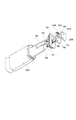
図2に、本発明の実施形態に係るインクタンクの分解斜視図を示す。第1のインク貯留部800と第2のインク貯留部900は、1枚の可撓性のフィルムを2つの袋状に形成することで構成されている。第1の部材700には、第1の舟型形状部710と第2の舟型形状部720が形成されている。第1のインク貯留部800を第1の舟型形状部710に溶着し、第2のインク貯留部900を第2の舟型形状部720に溶着することで密閉可能なインク貯留部が形成できる。タンクケース1000内部を仕切って第1のインク貯留部800と第2のインク貯留部900を別に設け、加圧供給時の圧力が第2のインク貯留部900に影響しないように構成することもできる。第1のインク導出経路410と第2のインク導出経路420と分岐点430は、溝(不図示)を設けた第2の部材730と第三の部材740を圧着させることで構成されている。インクタンク1には半導体メモリーなどの記憶媒体1040を設けることでインクの貯留量等を記憶させ第1のインク貯留部800のインク量を把握し、インクタンク1の交換時期を報知することができる。インク供給接続口1010には、インクタンク1を着脱する際のインク漏れを防止するためにゴム弁1030が設けられている。またインクタンク1は、位置決め嵌合部としても用いることのできる圧力供給接続口1070と位置決め嵌合部1020の2軸を用いて装置本体2との位置決めを行う構成であるため、3次元方向の位置決めを容易に行うことができる。
FIG. 2 is an exploded perspective view of the ink tank according to the embodiment of the present invention. The first
(インク攪拌動作)
第1のインク供給経路22やサブタンク20に貯留されたインクを長時間同じ状態で保持しているとインク中の顔料粒子が沈降するため、インク攪拌動作が行われる。本実施例におけるインクジェット記録システムにおけるインクの攪拌動作について図3〜図5を用いて説明する。図3は、本発明の実施形態に係るインクタンクからサブタンクへインクを供給するときの動作を説明する図である。図4は、本発明の実施形態に係るインクを攪拌するときの動作を説明する図である。図5は、本発明の実施形態に係るインクを攪拌するときの動作を説明するフローチャートである。
(Ink stirring operation)
When the ink stored in the first
インクタンク1を装置本体2に装着すると、図3のように加圧ポンプ40でインクタンク1内部が加圧され第1のインク貯留部800からサブタンク20へインクの供給が行われる。サブタンク20へのインク供給が終了すると、図5のS101で第1の弁24及び第2の弁25が閉鎖される。S102でサブタンク20内部が加減圧ポンプ21で加圧される。この加減圧ポンプ21で加圧する工程を第1の工程とする。この時タンクケース1000内部は大気開放されており、第1のインク貯留部800および第2のインク貯留部900に圧力はかかっていない。従って第1のインク貯留部800および第2のインク貯留部900内部の圧力は大気圧であり、サブタンク20内のみ加減圧ポンプ21により加圧されている。
When the ink tank 1 is attached to the apparatus main body 2, the inside of the ink tank 1 is pressurized by the
第2の工程としてS103で第1の弁24を開放すると、図4のようにサブタンク20内のインクは第1のインク供給経路22を通ってインクタンク1のインク供給接続口1010に送られる。インクタンク1に送られたインクは、インク供給接続口1010から第1のインク導出経路410及び第2のインク導出経路410を通って第2のインク貯留部900に送られる。このとき、第2のインク貯留部900内とサブタンク20内で圧力差があるため、サブタンク20内のインクは第2のインク貯留部900へと勢い良く流れ込む。これにより図4示す矢印のようにインクの流れが発生し、沈降した顔料成分を巻き上げることでインクが撹拌される。第1のインク導出経路410には一方向弁400が設けられているため、サブタンク20から第2のインク貯留部900にインクが勢い良く戻されたときに、第1のインク貯留部800にインクが逆流することはない。一方向弁400は、第1のインク貯留部800からインク供給接続口1010へのインクの移動は許容するがインク供給接続口1010から第1のインク貯留部800へのインクの移動は許容しない。本実施例におけるインクタンク1の一方向弁400は、弁体350と圧縮バネ380で構成されている。サブタンク20から第2のインク貯留部900にインクが送られるとき、弁体350は圧縮バネ380で押さえられているのでインクが第1のインク貯留部800に入ることはない。サブタンク20から第2のインク貯留部900へ向かうインクの流れは、一定時間経過するとインクの粘性抵抗等により勢いを失うため、勢いが失われるまでのおよその時間を設定しておく。
When the
S104で設定された待機時間の経過後、第三の工程としてS105で加減圧ポンプ21によりサブタンク20の減圧が行われる。このとき、第2のインク導出経路420の流抵抗は、(第1のインク貯留部800と分岐点430間の第1のインク導出経路410の流抵抗)+(一方向弁400の開弁圧)よりも小さくなるように設定されている。すなわち、第2のインク導出経路420の流抵抗は、第1のインク導出経路410の第1のインク貯留部800から第2のインク導出経路420が合流する部位までの流抵抗に一方向弁400の流抵抗を加えたものよりも小さい。そのため、第1のインク貯留部800に貯留されているインクよりも先に第2のインク貯留部900に送られたインクがサブタンク20に供給される。すなわち、加減圧ポンプ21を駆動してサブタンク内を減圧することにより第2のインク貯留部900に戻したインクが再度前記サブタンク20に供給される。S106で、第2のインク貯留部900からサブタンク20にインクが送られる十分な時間である規定時間の経過後、S107で第1の弁24を閉鎖し攪拌動作が終了される。
After the elapse of the standby time set in S104, the
以上のように図5のフローチャートに従って攪拌動作を行うことで、インクの沈降による画質低下を防止することができる。しかし長時間攪拌動作が行われていない場合は、1度の攪拌動作でインクの顔料粒子を攪拌できないことも考えられる。本実施形態では、前回の攪拌動作からの経過時間に応じて、攪拌動作を複数回繰り返すように制御している。図6に、本発明の実施形態に係るインクの攪拌回数を決定するフローチャートを示す。 As described above, by performing the stirring operation according to the flowchart of FIG. 5, it is possible to prevent deterioration in image quality due to ink sedimentation. However, when the stirring operation is not performed for a long time, it is also considered that the pigment particles of the ink cannot be stirred by one stirring operation. In the present embodiment, the stirring operation is controlled to be repeated a plurality of times according to the elapsed time from the previous stirring operation. FIG. 6 shows a flowchart for determining the number of ink agitation according to the embodiment of the present invention.
図6において、前回の攪拌動作が行われてからの経過時間をT0とし、攪拌動作が必要となると考えられる閾値である所定の経過時間をT1とし、前回からの経過時間が長時間で多回数の攪拌動作が必要であると考えられる閾値である所定の経過時間をT2とする。図6において、S201で攪拌動作が行われてからの経過時間をタイマー(不図示)で算出し、S202で攪拌動作が必要となるT1とT0を比較する。T0がT1より小さい場合は、攪拌動作を行わずに終了する。T0がT1よりも大きい場合には、S203に進む。S203で、T2とT0の比較を行う。T0がT2より小さい場合S204に進み、T0がT2より大きい場合はS205に進む。S204及びS205で、各経過時間における顔料粒子の沈降を回復するのに必要な攪拌回数N0を設定することができ、S204ではN0=N1、S205はN0=N2と設定する。N1、N2は、インクの特性、サブタンクに貯留されているインク量等によって決定される。 In FIG. 6, the elapsed time from the previous stirring operation is T0, the predetermined elapsed time, which is a threshold that the stirring operation is considered necessary, is T1, and the elapsed time from the previous time is long and many times. Let T2 be a predetermined elapsed time that is a threshold that is considered to require the stirring operation. In FIG. 6, the elapsed time since the stirring operation is performed in S201 is calculated by a timer (not shown), and T1 and T0 that require the stirring operation are compared in S202. When T0 is smaller than T1, the process is terminated without performing the stirring operation. When T0 is larger than T1, the process proceeds to S203. In S203, T2 and T0 are compared. If T0 is smaller than T2, the process proceeds to S204, and if T0 is larger than T2, the process proceeds to S205. In S204 and S205, the number of stirring times N0 required to recover the sedimentation of the pigment particles at each elapsed time can be set. In S204, N0 = N1, and in S205, N0 = N2. N1 and N2 are determined by ink characteristics, the amount of ink stored in the sub tank, and the like.
S206で、攪拌回数としてN=0を入力する。S207で攪拌動作を行い、S208でN=N+1を入力する。S209でNがN0となったか判断する。NがN0となっていない場合は、S207に戻り攪拌動作を行う。NがN0となった場合は、S210に進み攪拌回数をN=0にリセットし、攪拌動作を終了する。 In S206, N = 0 is input as the number of times of stirring. Stirring operation is performed in S207, and N = N + 1 is input in S208. In S209, it is determined whether N becomes N0. If N is not N0, the process returns to S207 to perform the stirring operation. When N becomes N0, the process proceeds to S210, the number of stirring is reset to N = 0, and the stirring operation is finished.
以上のように、本発明によればインクタンク1内部に設けられた第2のインク貯留部900とサブタンク20の間を、サブタンク20に設けた加減圧ポンプ21を用いてインクを勢い良く往復させることで、インクの攪拌動作を行うことができる。これにより記録動作に必要の無い経路を設けなくてもインクの攪拌が行え、インク中の顔料粒子の沈降による画質低下の発生を防止でき、信頼性の高い記録動作を行うことができる。
As described above, according to the present invention, the ink is vigorously reciprocated between the
(インクタンクの物流時)
インクタンクの物流時、第1のインク貯留部800にはインクが充填されている。このとき、第2のインク貯留部900は第1のインク貯留部800のバッファとして機能するようにさせたほうがよい。すなわち、第1のインク貯留部800内のインクまたは空気が温度変化や気圧の変化により体積膨張して第1のインク貯留部800内のインクが溢れ出したときに、第2のインク貯留部900で貯留するようにすることができる。そのため、第2のインク貯留部900には、物流時にインクを容量一杯に貯留させるべきではない。以上のように、インクタンク内部に第2のインク貯留部900を設け、物流時にバッファ部としても利用することで、更に信頼性の高いインクタンクを提供することができる。
(Ink tank logistics)
During the distribution of the ink tank, the first
本発明の実施形態によればサブタンクからインクタンク内部に設けられた第2のインク貯留部へ、圧力調整機構を用いてインクを勢い良く送ることでインクの攪拌動作を行え、インクジェット記録動作に必要の無い経路を設けなくてもインクの攪拌を行うことができる。これによりインク中の顔料粒子の沈降による画質低下を防止することができる信頼性の高い記録動作を行うインクタンク及び記録装置を提供することができる。 According to the embodiment of the present invention, the ink can be vigorously sent from the sub-tank to the second ink reservoir provided inside the ink tank by using the pressure adjustment mechanism, so that the ink can be agitated, which is necessary for the ink jet recording operation. The ink can be stirred without providing a path without any ink. Accordingly, it is possible to provide an ink tank and a recording apparatus that perform a highly reliable recording operation that can prevent image quality deterioration due to sedimentation of pigment particles in the ink.
1 インクタンク
2 記録装置
20 サブタンク
21 加減圧ポンプ
22 第1のインク供給経路
24 第1の弁
30 記録ヘッド
40 加圧ポンプ
400 一方向弁
410 第1のインク導出経路
420 第2のインク導出経路
430 分岐点
800 第1のインク貯留部
900 第2のインク貯留部
1000 タンクケース
1010 インク供給接続口
1070 圧力供給接続口
DESCRIPTION OF SYMBOLS 1 Ink tank 2
Claims (12)
前記記録装置に装着したときに装置本体と接続されインクを供給可能なインク供給接続口と、
前記サブタンクに供給するインクを貯留する第1のインク貯留部と、
前記第1のインク貯留部に貯留されたインクを前記インク供給接続口に供給するための第1のインク導出経路と、
前記サブタンクから戻したインクを貯留可能な第2のインク貯留部と、
前記第2のインク貯留部に貯留されたインクを前記インク供給接続口に供給するための第2のインク導出経路と、
を備え、前記第1のインク導出経路に、前記第1のインク貯留部から前記インク供給接続口へのインクの移動は許容するが前記インク供給接続口から前記第1のインク貯留部へのインクの移動は許容しない一方向弁を設けることを特徴とするインクタンク。 In an ink tank that can be attached to a recording apparatus comprising: a recording head that ejects ink; and a sub tank that stores ink to be supplied to the recording head
An ink supply connection port connected to the apparatus main body and capable of supplying ink when mounted on the recording apparatus;
A first ink storage section for storing ink to be supplied to the sub tank;
A first ink outlet path for supplying ink stored in the first ink storage section to the ink supply connection port;
A second ink storage unit capable of storing ink returned from the sub tank;
A second ink lead-out path for supplying the ink stored in the second ink storage section to the ink supply connection port;
The ink is allowed to move from the first ink reservoir to the ink supply connection port in the first ink lead-out path, but the ink from the ink supply connection port to the first ink reservoir is ink tank moving is characterized by kick set a one-way valve that does not permit the.
前記インクタンクは、前記装置本体に装着したときに該装置本体と接続されインクを供給可能なインク供給接続口と、前記サブタンクに供給するインクを貯留する第1のインク貯留部と、前記第1のインク貯留部に貯留されたインクを前記インク供給接続口に供給するための第1のインク導出経路と、前記サブタンクから戻したインクを貯留可能な第2のインク貯留部と、前記第2のインク貯留部に貯留されたインクを前記インク供給接続口に供給するための第2のインク導出経路と、を備え、前記第1のインク導出経路に、前記第1のインク貯留部から前記インク供給接続口へのインクの移動は許容するが前記インク供給接続口から前記第1のインク貯留部へのインクの移動は許容しない一方向弁を設け、前記第2のインク導出経路は前記第1のインク導出経路に前記一方向弁と前記インク供給接続口との間で合流することを特徴とする記録装置。 In a recording apparatus comprising: a recording head that ejects ink; a sub tank that stores ink to be supplied to the recording head; and an ink tank that can be attached to the apparatus main body.
The ink tank is connected to the apparatus main body when attached to the apparatus main body and is capable of supplying ink, a first ink storage section for storing ink to be supplied to the sub tank, and the first A first ink lead-out path for supplying the ink stored in the ink storage section to the ink supply connection port, a second ink storage section capable of storing the ink returned from the sub tank, and the second ink storage section. A second ink outlet path for supplying the ink stored in the ink reservoir to the ink supply connection port, and the ink supply from the first ink reservoir to the first ink outlet path. A one-way valve is provided that allows ink movement to the connection port but does not allow ink movement from the ink supply connection port to the first ink reservoir. Recording apparatus characterized by merge between 1 and the one-way valve in the ink outlet path the ink supply connection port.
Priority Applications (1)
| Application Number | Priority Date | Filing Date | Title |
|---|---|---|---|
| JP2009245807A JP5404307B2 (en) | 2008-12-19 | 2009-10-26 | Ink tank and recording apparatus |
Applications Claiming Priority (3)
| Application Number | Priority Date | Filing Date | Title |
|---|---|---|---|
| JP2008324173 | 2008-12-19 | ||
| JP2008324173 | 2008-12-19 | ||
| JP2009245807A JP5404307B2 (en) | 2008-12-19 | 2009-10-26 | Ink tank and recording apparatus |
Publications (3)
| Publication Number | Publication Date |
|---|---|
| JP2010162869A JP2010162869A (en) | 2010-07-29 |
| JP2010162869A5 JP2010162869A5 (en) | 2012-12-13 |
| JP5404307B2 true JP5404307B2 (en) | 2014-01-29 |
Family
ID=41821844
Family Applications (1)
| Application Number | Title | Priority Date | Filing Date |
|---|---|---|---|
| JP2009245807A Active JP5404307B2 (en) | 2008-12-19 | 2009-10-26 | Ink tank and recording apparatus |
Country Status (6)
| Country | Link |
|---|---|
| US (1) | US8622530B2 (en) |
| EP (1) | EP2202079B1 (en) |
| JP (1) | JP5404307B2 (en) |
| KR (1) | KR101252902B1 (en) |
| CN (1) | CN101746148B (en) |
| AT (1) | ATE518660T1 (en) |
Families Citing this family (18)
| Publication number | Priority date | Publication date | Assignee | Title |
|---|---|---|---|---|
| JP5321969B2 (en) * | 2009-07-30 | 2013-10-23 | 株式会社リコー | Image forming apparatus |
| JP5552778B2 (en) * | 2009-09-02 | 2014-07-16 | セイコーエプソン株式会社 | Liquid supply method |
| JP2011110853A (en) * | 2009-11-27 | 2011-06-09 | Mimaki Engineering Co Ltd | Liquid circulating system |
| JP2011110851A (en) * | 2009-11-27 | 2011-06-09 | Mimaki Engineering Co Ltd | Liquid circulating system |
| US8550612B2 (en) * | 2010-10-20 | 2013-10-08 | Xerox Corporation | Method and system for ink delivery and purged ink recovery in an inkjet printer |
| JP5811322B2 (en) * | 2011-05-19 | 2015-11-11 | 株式会社リコー | Image forming apparatus |
| JP5899732B2 (en) * | 2011-09-14 | 2016-04-06 | セイコーエプソン株式会社 | Liquid ejection device |
| JP2013159037A (en) * | 2012-02-06 | 2013-08-19 | Seiko Epson Corp | Liquid container, liquid container set, and inkjet recorder |
| JP5861504B2 (en) * | 2012-03-07 | 2016-02-16 | セイコーエプソン株式会社 | Liquid ejecting apparatus, liquid stirring method, and liquid filling method |
| JP6102167B2 (en) * | 2012-10-10 | 2017-03-29 | セイコーエプソン株式会社 | Printing device |
| CN104309307A (en) * | 2014-10-02 | 2015-01-28 | 合肥海闻自动化设备有限公司 | Ink circulating system for tire digital printer |
| US9981475B2 (en) * | 2014-12-10 | 2018-05-29 | Canon Kabushiki Kaisha | Ink supply apparatus and ink jet recording apparatus |
| JP6786243B2 (en) * | 2016-04-05 | 2020-11-18 | キヤノン株式会社 | Ink supply device and inkjet recording device |
| US10759181B2 (en) * | 2017-07-07 | 2020-09-01 | Canon Kabushiki Kaisha | Inkjet printing apparatus and control method of the inkjet printing apparatus |
| IT201700102152A1 (en) * | 2017-09-13 | 2019-03-13 | Jet Set S R L | PRESS SYSTEM AND ITS METHOD |
| CN111819083B (en) * | 2018-03-08 | 2022-03-29 | 惠普发展公司,有限责任合伙企业 | Attachment, dummy cartridge, method for inserting dummy cartridge into printer |
| JP7341703B2 (en) * | 2019-04-02 | 2023-09-11 | キヤノン株式会社 | liquid discharge head |
| US10913285B2 (en) | 2019-07-02 | 2021-02-09 | Electronics For Imaging, Inc. | Multi-color multi-speed printing apparatus with circulation |
Family Cites Families (16)
| Publication number | Priority date | Publication date | Assignee | Title |
|---|---|---|---|---|
| JPS59227456A (en) * | 1983-06-09 | 1984-12-20 | Canon Inc | Ink jet printer |
| JPS63118259A (en) * | 1987-07-21 | 1988-05-23 | Canon Inc | Tank cassette |
| US5798781A (en) * | 1995-05-02 | 1998-08-25 | Pedersen; Niels B. | Printer |
| JP3684022B2 (en) * | 1996-04-25 | 2005-08-17 | キヤノン株式会社 | Liquid replenishment method, liquid discharge recording apparatus, and ink tank used as a main tank of the liquid discharge recording apparatus |
| JPH09327929A (en) * | 1996-06-07 | 1997-12-22 | Seiko Epson Corp | Ink jet type recording device |
| JPH10181043A (en) | 1996-12-26 | 1998-07-07 | Canon Inc | Liquid ejection recorder |
| JP2002001992A (en) * | 2000-06-19 | 2002-01-08 | Seiko Epson Corp | Ink-jet-type recording device, and method for stirring ink stored in sub-tank |
| GB0113093D0 (en) * | 2001-05-30 | 2001-07-18 | 3M Innovative Properties Co | Inkjet printing |
| JP3754954B2 (en) * | 2002-11-27 | 2006-03-15 | キヤノン株式会社 | Liquid container and inkjet recording apparatus |
| JP2005144954A (en) * | 2003-11-18 | 2005-06-09 | Toshiba Tec Corp | Ink jet unit |
| JP4769499B2 (en) * | 2005-07-08 | 2011-09-07 | 富士フイルム株式会社 | Ink cartridge, ink jet recording apparatus, and waste ink cartridge |
| JP4816261B2 (en) * | 2006-06-05 | 2011-11-16 | 富士ゼロックス株式会社 | Droplet discharge device |
| JP2008055646A (en) | 2006-08-29 | 2008-03-13 | Toshiba Tec Corp | Inkjet recording apparatus, and ink feeding method for the recording apparatus |
| JP2008273027A (en) | 2007-04-27 | 2008-11-13 | Seiko Epson Corp | Liquid feeder and liquid ejector |
| JP2008273043A (en) | 2007-04-27 | 2008-11-13 | Canon Inc | Liquid storage container, head cartridge, and ink-jet recording device |
| KR20080100933A (en) * | 2007-05-15 | 2008-11-21 | 삼성전기주식회사 | Injection apparutus of ink and injection method thereof |
-
2009
- 2009-10-26 JP JP2009245807A patent/JP5404307B2/en active Active
- 2009-12-16 AT AT09179510T patent/ATE518660T1/en not_active IP Right Cessation
- 2009-12-16 EP EP09179510A patent/EP2202079B1/en active Active
- 2009-12-17 CN CN2009102612232A patent/CN101746148B/en active Active
- 2009-12-17 US US12/640,176 patent/US8622530B2/en active Active
- 2009-12-18 KR KR1020090126608A patent/KR101252902B1/en active IP Right Grant
Also Published As
| Publication number | Publication date |
|---|---|
| EP2202079B1 (en) | 2011-08-03 |
| US8622530B2 (en) | 2014-01-07 |
| KR101252902B1 (en) | 2013-04-09 |
| EP2202079A1 (en) | 2010-06-30 |
| CN101746148A (en) | 2010-06-23 |
| JP2010162869A (en) | 2010-07-29 |
| ATE518660T1 (en) | 2011-08-15 |
| CN101746148B (en) | 2011-11-02 |
| KR20100071922A (en) | 2010-06-29 |
| US20100157002A1 (en) | 2010-06-24 |
Similar Documents
| Publication | Publication Date | Title |
|---|---|---|
| JP5404307B2 (en) | Ink tank and recording apparatus | |
| JP5615392B2 (en) | Liquid storage container and apparatus capable of mounting the same | |
| JP4384067B2 (en) | Liquid ejecting apparatus and liquid processing method | |
| JP5599077B2 (en) | Inkjet printing device | |
| JP2018058255A (en) | Liquid injection device and fluid discharge method for the same | |
| JP2010023500A (en) | Recording head and recording apparatus | |
| JP5599693B2 (en) | Inkjet printer regulator and inkjet printer | |
| JP3363760B2 (en) | Ink supply device and printing device | |
| JP3347688B2 (en) | Ink tank, inkjet cartridge, and inkjet recording device | |
| JP2009023251A (en) | Inkjet recording apparatus | |
| JP2016107436A (en) | Liquid injection device | |
| JP2002200773A (en) | Ink tank, ink jet cartridge, ink feed unit, ink jet recorder, and ink feed method | |
| JP2013039815A (en) | Liquid supply device and liquid ejecting apparatus | |
| JP2003211685A (en) | Liquid storage container and head cartridge using the same | |
| JP2019025663A (en) | Liquid storage container and liquid discharge device | |
| JP6930320B2 (en) | Liquid injection device, liquid discharge method of liquid injection device | |
| JP2004181952A (en) | Ink storage, inkjet head structure body having the same, and ink jet recorder | |
| JP2003211686A (en) | Liquid storage container and head cartridge using the same | |
| JP2001301194A (en) | Ink tank, ink jet cartridge, ink supply unit, ink jet recorder, and method for supplying ink | |
| JP2009262446A (en) | Waste liquid collecting unit | |
| CN108357213B (en) | The driving method of liquid ejection apparatus and liquid ejection apparatus | |
| JP4912999B2 (en) | Ink jet device and method of operating ink jet device | |
| JP2007160861A (en) | Ink storage container and ink stirring system using ink storage container | |
| JP2004066463A (en) | Liquid drop ejection recorder and its ink filling method | |
| JP2012081591A (en) | Ink-jet printer |
Legal Events
| Date | Code | Title | Description |
|---|---|---|---|
| RD01 | Notification of change of attorney |
Free format text: JAPANESE INTERMEDIATE CODE: A7421 Effective date: 20100630 |
|
| A521 | Request for written amendment filed |
Free format text: JAPANESE INTERMEDIATE CODE: A523 Effective date: 20121026 |
|
| A621 | Written request for application examination |
Free format text: JAPANESE INTERMEDIATE CODE: A621 Effective date: 20121026 |
|
| A977 | Report on retrieval |
Free format text: JAPANESE INTERMEDIATE CODE: A971007 Effective date: 20130924 |
|
| TRDD | Decision of grant or rejection written | ||
| A01 | Written decision to grant a patent or to grant a registration (utility model) |
Free format text: JAPANESE INTERMEDIATE CODE: A01 Effective date: 20131001 |
|
| A61 | First payment of annual fees (during grant procedure) |
Free format text: JAPANESE INTERMEDIATE CODE: A61 Effective date: 20131029 |
|
| R151 | Written notification of patent or utility model registration |
Ref document number: 5404307 Country of ref document: JP Free format text: JAPANESE INTERMEDIATE CODE: R151 |