JP6626671B2 - Building damping structure - Google Patents
Building damping structure Download PDFInfo
- Publication number
- JP6626671B2 JP6626671B2 JP2015177429A JP2015177429A JP6626671B2 JP 6626671 B2 JP6626671 B2 JP 6626671B2 JP 2015177429 A JP2015177429 A JP 2015177429A JP 2015177429 A JP2015177429 A JP 2015177429A JP 6626671 B2 JP6626671 B2 JP 6626671B2
- Authority
- JP
- Japan
- Prior art keywords
- piston
- hydraulic damper
- oil
- hydraulic
- building
- Prior art date
- Legal status (The legal status is an assumption and is not a legal conclusion. Google has not performed a legal analysis and makes no representation as to the accuracy of the status listed.)
- Active
Links
- 238000013016 damping Methods 0.000 title claims description 105
- 238000006073 displacement reaction Methods 0.000 claims description 47
- 239000000463 material Substances 0.000 claims description 37
- 230000005540 biological transmission Effects 0.000 claims description 31
- 239000007789 gas Substances 0.000 claims description 23
- 239000011229 interlayer Substances 0.000 claims description 22
- 230000008859 change Effects 0.000 claims description 17
- 230000002093 peripheral effect Effects 0.000 claims description 13
- 230000007246 mechanism Effects 0.000 claims description 10
- 230000001105 regulatory effect Effects 0.000 claims description 7
- 239000011261 inert gas Substances 0.000 claims description 6
- 230000009471 action Effects 0.000 claims description 4
- 230000008602 contraction Effects 0.000 description 13
- 230000006835 compression Effects 0.000 description 5
- 238000007906 compression Methods 0.000 description 5
- 238000010521 absorption reaction Methods 0.000 description 4
- 238000005452 bending Methods 0.000 description 4
- 239000000428 dust Substances 0.000 description 4
- 230000000694 effects Effects 0.000 description 4
- 230000036316 preload Effects 0.000 description 4
- 230000001133 acceleration Effects 0.000 description 3
- 230000006378 damage Effects 0.000 description 3
- 239000002184 metal Substances 0.000 description 3
- 230000035939 shock Effects 0.000 description 3
- 239000003190 viscoelastic substance Substances 0.000 description 3
- 239000002023 wood Substances 0.000 description 3
- 230000003111 delayed effect Effects 0.000 description 2
- 230000007774 longterm Effects 0.000 description 2
- 230000004044 response Effects 0.000 description 2
- XLYOFNOQVPJJNP-UHFFFAOYSA-N water Substances O XLYOFNOQVPJJNP-UHFFFAOYSA-N 0.000 description 2
- IJGRMHOSHXDMSA-UHFFFAOYSA-N Atomic nitrogen Chemical compound N#N IJGRMHOSHXDMSA-UHFFFAOYSA-N 0.000 description 1
- 229910000831 Steel Inorganic materials 0.000 description 1
- 239000006096 absorbing agent Substances 0.000 description 1
- QVGXLLKOCUKJST-UHFFFAOYSA-N atomic oxygen Chemical compound [O] QVGXLLKOCUKJST-UHFFFAOYSA-N 0.000 description 1
- 238000010276 construction Methods 0.000 description 1
- 230000008878 coupling Effects 0.000 description 1
- 238000010168 coupling process Methods 0.000 description 1
- 238000005859 coupling reaction Methods 0.000 description 1
- 125000004122 cyclic group Chemical group 0.000 description 1
- 230000003247 decreasing effect Effects 0.000 description 1
- 230000006866 deterioration Effects 0.000 description 1
- 238000010586 diagram Methods 0.000 description 1
- 229910001873 dinitrogen Inorganic materials 0.000 description 1
- 230000007613 environmental effect Effects 0.000 description 1
- 239000002783 friction material Substances 0.000 description 1
- JEIPFZHSYJVQDO-UHFFFAOYSA-N iron(III) oxide Inorganic materials O=[Fe]O[Fe]=O JEIPFZHSYJVQDO-UHFFFAOYSA-N 0.000 description 1
- 239000007788 liquid Substances 0.000 description 1
- 238000000034 method Methods 0.000 description 1
- 230000004048 modification Effects 0.000 description 1
- 238000012986 modification Methods 0.000 description 1
- 230000007935 neutral effect Effects 0.000 description 1
- 239000001301 oxygen Substances 0.000 description 1
- 229910052760 oxygen Inorganic materials 0.000 description 1
- 238000005192 partition Methods 0.000 description 1
- 238000003825 pressing Methods 0.000 description 1
- 230000000750 progressive effect Effects 0.000 description 1
- 230000002035 prolonged effect Effects 0.000 description 1
- 230000000644 propagated effect Effects 0.000 description 1
- 230000003014 reinforcing effect Effects 0.000 description 1
- 230000002441 reversible effect Effects 0.000 description 1
- 238000007790 scraping Methods 0.000 description 1
- 125000006850 spacer group Chemical group 0.000 description 1
- 239000010959 steel Substances 0.000 description 1
- 230000001131 transforming effect Effects 0.000 description 1
- 238000003466 welding Methods 0.000 description 1
Images


Description
本発明は、建物、特に木造建物に用いて好適であり、詳しくは油圧ダンパを用いた建物の制振構造に関する。 The present invention is suitable for use in a building, particularly a wooden building, and more particularly to a building vibration control structure using a hydraulic damper.
従来、並行する2本の柱材と、一方の柱材の例えば中央部に取付けたダンパー体と、一端をダンパー体に取付け、他端部を他方の柱材の高さの異なる位置、例えば上端及び下端にそれぞれ取付けた複数本、例えば2本のブレース材と、を備えた木造建物の制振構造が案出されている(特許文献1)。該特許文献1のものは、ダンパー体として、粘弾性材(実施例1)、降伏して塑性変形する弾塑性ダンパ(実施例2)、又は摩擦材の摩擦力で抵抗する摩耗ダンパ(実施例3)が用いられている。
Conventionally, two parallel pillar members, a damper body attached to, for example, a central portion of one pillar member, and one end attached to the damper body, and the other end portion having a different height of the other pillar member, for example, an upper end And a plurality of, for example, two brace members attached to the lower end and a lower end, respectively, have been devised (Patent Document 1).
上記制振構造は、柱材に生じる曲げ方向の力が抑えられて軸力が支配的になり、従って柱材の曲げ変形が防止又は抑制され、振動時の層間変形を小さく抑えることができ、またダンパー体が振動時のエネルギの大半をせん断抵抗として吸収できるため、ダンパー体の振動吸収効率を向上し得る。 The vibration damping structure is such that the force in the bending direction generated in the column material is suppressed and the axial force becomes dominant, so that the bending deformation of the column material is prevented or suppressed, and the interlayer deformation during vibration can be suppressed small, Moreover, since the damper body can absorb most of the energy during vibration as shear resistance, the vibration absorption efficiency of the damper body can be improved.
一方、シリンダ内にオイルを充填した油圧室を、ピストンにより2個の油室に区画して、2個の油室の間でオイルを所定の減衰力特性で連通する油圧ダンパを備え、前記ピストンに連結するピストンロッドの端部を一方の構造部材に連結すると共に、前記シリンダの端部を他方の構造部材に連結した構造物の制振装置が、本出願人により提案されている(特許文献2)。 On the other hand, a hydraulic chamber filled with oil in a cylinder is divided into two oil chambers by a piston, and a hydraulic damper for communicating oil with a predetermined damping force characteristic between the two oil chambers is provided. A vibration damping device for a structure in which an end of a piston rod connected to a cylinder is connected to one structural member and an end of the cylinder is connected to the other structural member has been proposed by the present applicant. 2).
前記構造物の制振装置の油圧ダンパは、シリンダに対するピストンの移動速度が所定値以下の状態では、オイルの流れを制限して、前記移動速度に対する荷重変化の大きい急勾配で立上がる減衰特性の大きい剛体の近い状態となり、前記移動速度が前記所定値より速い状態ではオイルの流れを許容し、移動速度に対する荷重変化の小さい緩勾配からなる減衰特性の小さい制振状態となるように設定してある。 The hydraulic damper of the vibration damping device for the structure has a damping characteristic that, when the moving speed of the piston with respect to the cylinder is equal to or less than a predetermined value, restricts the flow of oil and rises at a steep slope with a large load change relative to the moving speed. In a state close to a large rigid body, in a state where the moving speed is faster than the predetermined value, oil flow is allowed, and a setting is made such that a damping characteristic having a small damping characteristic including a gentle slope with a small load change with respect to the moving speed is set. is there.
これにより、弱い地震、道路等からの振動等の小さいエネルギに対しては、構造物の揺れを抑えて、建物の居住性等の構造物の品質を維持すると共に、強地震等による大きなエネルギに対しては、該エネルギを吸収して、建物等の構造物の破壊を有効に防止して耐震性を向上する。 As a result, with respect to small energies such as weak earthquakes and vibrations from roads, etc., the sway of the structures is suppressed, and the quality of the structures such as the livability of the buildings is maintained. On the other hand, by absorbing the energy, the structure such as a building is effectively prevented from being destroyed, and the earthquake resistance is improved.
前記特許文献1の制振構造は、ダンパー体が一方の柱材の中央部に取付けられ、2本のブレース材の他端が他方の柱材の上端部及び下端部に取付けられている場合(以下Kブレース構造という)、横架材の幅方向の層間変位(X)に対してダンパー体における相対変位(Y)の比率(Y/X)である作動効率eは、約0.3となる。即ち、該特許文献1の従来の技術に示されるように(該特許文献1の図16(b)参照)、上下の横架材に、伝動部材を介してダンパー体を架け渡して設置したものは、層間変位Xがそのままダンパー体の相対変位Yとなって(X=Y)、作動効率e=1となるが、このものに比し、上記特許文献1のものは、相対変位が約(1/3)となり、変位量が小さい分、ダンパー体には大きな反発力が必要となる。
In the vibration damping structure of
しかし、ダンパー体としての粘弾性材は、小さな変位では小さな力で、変位が大きくなるに従って力も増大するプログレッシブ特性であり、上記Kブレース構造とのマッチングがよくなく、かつ温度依存性が高く、環境温の影響を受け易い減衰特性となる。また、大きな地震で揺れが大きい場合、変位が過大となって粘弾性材が破断又は剪断する虞がある。 However, the viscoelastic material as the damper body has a progressive characteristic in which a small displacement at a small displacement and a force increases as the displacement increases, the matching with the K-brace structure is not good, and the temperature dependency is high, and The damping characteristics are easily affected by temperature. Further, when the shaking is large due to a large earthquake, the displacement becomes excessive and the viscoelastic material may be broken or sheared.
金属による弾塑性ダンパは、変形初期は、弾性変形し、塑性変形が始まると略々一定の力となり、変位が大きくなると少ない振動回数で破断する。従って、該弾塑性ダンパを用いた上記制振構造(Kブレース構造)は、金属の塑性変形領域を利用するため、繰返しの振動(変形)が加わると破断の虞がある。従って、大きな地震の後には何度も余震が発生することを考慮すると、信頼性が充分でない。また、一度建物が変形すると、元に戻す復元力はなく、上記弾塑性ダンパが塑性変形すると木造建物が本来有する復元力を妨げて、却って建物を傾いたままにしてしまう。 The elasto-plastic damper made of metal is elastically deformed in the initial stage of deformation, becomes a substantially constant force when plastic deformation starts, and breaks with a small number of vibrations when the displacement becomes large. Therefore, the above-described vibration damping structure (K-brace structure) using the elasto-plastic damper utilizes a plastic deformation region of metal, and thus may be broken when repeated vibration (deformation) is applied. Therefore, the reliability is not enough considering that aftershocks occur many times after a large earthquake. In addition, once the building is deformed, there is no restoring force to return to its original state. When the elasto-plastic damper is plastically deformed, the original restoring force of the wooden building is hindered, and the building is left tilted.
前記摩擦ダンパは、小さな力に対しては大きな力(抵抗力)を発生し、大きな力に対して小さな力(抵抗力)となる、制振装置として望ましい特性(バイリニア特性)を発揮するが、摩擦力の調整、具体的には摩擦材を押付けるボルトナットの締付力の調整が面倒であり、かつそれが長期間保持される保障も確実ではない。また、一度摩擦ダンパが相対移動すると、該ずれた位置に固定するように作用し、木造建物の弾性復元力に抗することとなり、価額が高価になることも相俟って、木造建物の制振構造に適用することは困難である。 Although the friction damper generates a large force (resistance force) for a small force and has a small force (resistance force) for a large force, it exhibits a characteristic (bilinear characteristic) desirable as a vibration damping device. Adjustment of the frictional force, specifically, the adjustment of the tightening force of the bolt and nut for pressing the frictional material is troublesome, and it is not certain that it will be maintained for a long time. Also, once the friction damper moves once, it acts to fix it at the shifted position, resisting the elastic restoring force of the wooden building, and increasing the price. It is difficult to apply to a vibration structure.
特許文献2の油圧ダンパは、バイリニア特性、環境温度の変化、長期間の耐久性、復元性等、地震に対する構造物の制振装置として好適であるが、該特許文献2には、油圧ダンパ自体が梁等の横架材と柱材との間に斜めに取付けて用いられている。該油圧ダンパの方杖的用い方では、梁の変位(X)に対する油圧ダンパの変位(移動)Yの比率(Y/X)である作動効率eは、上述したKブレース構造に比して大幅に小さい。従って、油圧ダンパ自体は、所定ストローク伸縮して、エネルギを吸収できるのに拘らず、小ストロークで大きな荷重が作用する状態で用いられ、油圧ダンパの機能を十分に発揮できないと共に、油圧ダンパの効率が低くなる。このため、所定建物に対して上記油圧ダンパによる制振装置の取付け個数が多くなり、コストアップを招いてしまう。 The hydraulic damper of Patent Literature 2 is suitable as a vibration damping device for a structure against an earthquake, such as bilinear characteristics, changes in environmental temperature, long-term durability, resilience, and the like. Is used by being attached diagonally between a horizontal member such as a beam and a column member. In the use of the hydraulic damper as a cane, the operating efficiency e, which is the ratio (Y / X) of the displacement (movement) Y of the hydraulic damper to the displacement (X) of the beam, is significantly higher than that of the K-brace structure described above. Small. Therefore, the hydraulic damper itself is used in a state in which a large load acts on a small stroke regardless of being able to absorb and absorb energy by expanding and contracting a predetermined stroke, and the hydraulic damper cannot fully exhibit the function of the hydraulic damper. Becomes lower. For this reason, the number of vibration damping devices provided by the hydraulic damper to a predetermined building increases, which leads to an increase in cost.
そこで、本発明は、油圧ダンパを適正な作動効率で用いる制振構造として、油圧ダンパの性能を充分に発揮し、もって上述した課題を解決した建物の制振構造を提供することを目的とするものである。 Therefore, an object of the present invention is to provide a vibration damping structure for a building which fully demonstrates the performance of the hydraulic damper as a vibration damping structure using the hydraulic damper with an appropriate operation efficiency and thereby solves the above-mentioned problems. Things.
本発明は、並行する2本の柱材(105)(106)と、これら2本の柱材の上端及び下端に接合した並行する2本の横架材(102)(103)と、から構成される構造体(101)を有する建物の制振構造であって、
前記構造体(101)内に配置され、前記2本の横架材の層間変位(X)を作動変位(Y)として伝達する伝達手段(U)と、
前記伝達手段(U)の作動変位(Y)を吸収する油圧ダンパ(1)と、を備えた、
ことを特徴とする。
前記伝達手段は、前記2本の柱材の内の一方の柱材(105)における高さの異なる少なくとも2箇所で連結して、他方の柱材側(106)における前記一方の柱材の連結部の高さ方向中間部に、前記作動変位(Y)として伝達してなる、
ことを特徴とする。
The present invention comprises two parallel column members (105) and (106) and two parallel horizontal members (102) and (103) joined to the upper and lower ends of these two column members. Damping structure of a building having a structure (101) to be
A transmission means (U) disposed in the structure (101) for transmitting an interlayer displacement (X) of the two transverse members as an actuation displacement (Y);
A hydraulic damper (1) for absorbing the operating displacement (Y) of the transmission means (U).
It is characterized by the following.
The transmission means connects at least two different heights of one pillar (105) of the two pillars, and connects the one pillar on the other pillar side (106). Transmitted to the intermediate portion in the height direction of the portion as the operating displacement (Y),
It is characterized by the following.
例えば図1,図8を参照して、前記伝達手段(U)は、前記一方の柱材(105)の上端部(105a)及び下端部(105b)にそれぞれ連結(A)(B)すると共に、前記中間部(C),(C1,C2)にて互いに連結するブレース構造(U)であり、
前記油圧ダンパ(1)は、前記ブレース構造(U)の中間部(C),(C1,C2)と前記他方の柱材(106)との間に介在されてなる。
For example, referring to FIGS. 1 and 8, the transmission means (U) is connected (A) and (B) to the upper end (105a) and the lower end (105b) of the one pillar (105), respectively. A brace structure (U) connected to each other at the intermediate portions (C) and (C1, C2);
The hydraulic damper (1) is interposed between intermediate portions (C) and (C1, C2) of the brace structure (U) and the other column member (106).
例えば図2,図4を参照して、前記伝達手段(U)は、前記一方の柱材(105)に固定された耐力壁材(114)(115)であり、該耐力壁材の前記他方の柱材側(114c)(115c)と前記他方の柱材(106)との間に前記油圧ダンパ(1)を介在してなる。 For example, with reference to FIGS. 2 and 4, the transmission means (U) is a load-bearing wall material (114) (115) fixed to the one pillar (105), and the other of the load-bearing wall materials. The hydraulic damper (1) is interposed between the column material side (114c) (115c) and the other column material (106).
例えば、図3を参照して、前記油圧ダンパ(11)(12)は、前記一方の柱材(105)の端部(105a)(105b)と前記他方の柱材(106)の中間部(113)との間に連結されてなる。 For example, referring to FIG. 3, the hydraulic dampers (1 1 ) and (1 2 ) are provided between the ends (105a) and (105b) of the one pillar (105) and the other pillar (106). (113).
例えば図5を参照して、前記伝達手段(U1)(U2)は、前記一方の柱材(105)の端部(105a)(105b)と前記他方の柱材の中間部(113)との間に連結されたトッグル機構(116,117)であり、
前記油圧ダンパ(11,12)は、前記トッグル機構(116)(117)の連結ピン(G1)(G2)と前記他方の柱材(106)との間に介在してなる。
For example, referring to FIG. 5, the transmission means (U1) (U2) is provided between an end (105a) (105b) of the one pillar (105) and an intermediate part (113) of the other pillar. A toggle mechanism (116, 117) connected therebetween,
The
例えば図6〜図7を参照して、前記伝達手段(U)は、前記一方の柱材(105)の上端部(105a)及び下端部(105b)にそれぞれ一端が連結される第1及び第2ブレース材(111)(112)と、前記他方の柱材(106)の中間部に一端(I)が連結され、かつ前記第1及び第2ブレース材(111)(112)の他端(C)(C1,C2)が連結されるレバー部材(117)と、を有し、
前記油圧ダンパ(11,12)は、前記レバー部材(117)の他端(J)(J1,J2)と前記一方の柱材(105)の間に介在され、
前記レバー部材(117)は、前記第1及び第2ブレース材(111)(112)の連結点(C)(C1,C2)を支点とし、前記一端の連結点(I)を力点とし、前記他端の連結点(J)(J1,J2)を作用点としたレバー比により、前記力点に作用する変位(Y)を前記作用点から前記油圧ダンパ(11,12)に変更して伝達してなる。
For example, referring to FIGS. 6 and 7, the transmission means (U) includes first and second ends each having one end connected to an upper end (105a) and a lower end (105b) of the one pillar (105). One end (I) is connected to an intermediate portion between the two brace members (111) and (112) and the other column member (106), and the other ends (the other ends) of the first and second brace members (111) and (112). C) a lever member (117) to which (C1, C2) is connected;
The
The lever member (117) has a connection point (C) (C1, C2) between the first and second brace members (111) and (112) as a fulcrum, and a connection point (I) at one end as a power point. The displacement (Y) acting on the force point is changed from the action point to the hydraulic damper (1 1 , 1 2 ) by the lever ratio with the connection point (J) (J1, J2) at the other end as the action point. Communicate.
例えば図9〜図19を参照して、前記油圧ダンパ(1)は、シリンダ(5)内にオイルを充填した油圧室(27)を1個のピストン(10)により2個の油室(27a)(27b)に区画し、前記シリンダ(5)に少なくとも軸方向に一体のエンド部材(19)と、前記シリンダに軸方向に移動自在なフロート部材(23)との間で前記油圧室(27)を形成してなり、
前記シリンダの端部の閉塞部(9)と前記フロート部材(23)との間に、前記油圧室(27)から前記フロート部材(23)に作用する油圧に対向する所定圧の不活性ガスが封入されているガス室(29)を形成し、
前記ピストン部分(10)に、前記2個の油室の一方(27a)から他方の油室(27b)へのオイルの流れを規制する第1のピストンバルブ(371)と、前記他方の油室(27b)から一方の油室(27a)へのオイルの流れを規制する第2のピストンバルブ(372)と、前記2個の油室(27a)(27b)を連通するオリフィス(61)と、を設け、
前記油圧ダンパ(1)は、前記第1及び第2のピストンバルブ(371)(372)がそれぞれ前記規制される流れと反対方向のオイルの流れに対して、前記シリンダ(5)に対する前記ピストン(10)の移動速度(V)が所定値(P)以下の状態では閉じ位置にあって前記オイルの流れを前記オリフィス(61)により制限し、移動速度に対する荷重変化が急勾配からなり、前記ピストンの移動速度(V)が前記所定値(P)より速い状態では開かれて前記オイルの流れを許容し、移動速度に対する荷重変化が小さい緩勾配からなる減衰力特性を有し、
前記オリフィス(61)は、前記シリンダの内径断面積(A)に対する該オリフィスの流通面積(a)の比である開口面積比率が0.004〜0.040である。
For example, referring to FIGS. 9 to 19, the hydraulic damper (1) is configured such that a hydraulic chamber (27) filled with oil in a cylinder (5) is divided into two oil chambers (27a) by one piston (10). ) (27b), and the hydraulic chamber (27) is provided between an end member (19) that is at least axially integral with the cylinder (5) and a float member (23) that is axially movable with the cylinder. ) To form
An inert gas of a predetermined pressure opposed to the hydraulic pressure acting on the float member (23) from the hydraulic chamber (27) is provided between the closed part (9) at the end of the cylinder and the float member (23). Forming an enclosed gas chamber (29);
A first piston valve (37 1 ) for regulating the flow of oil from one (27a) of the two oil chambers to the other oil chamber (27b); A second piston valve (37 2 ) for regulating the flow of oil from the chamber (27b) to one oil chamber (27a), and an orifice (61) communicating the two oil chambers (27a) (27b). And
The hydraulic damper (1) is configured to move the first and second piston valves (37 1 ) and (37 2 ) with respect to the cylinder (5) with respect to an oil flow in a direction opposite to a flow in which the restricted flow is restricted. When the moving speed (V) of the piston (10) is equal to or less than the predetermined value (P), the piston is in the closed position and the flow of the oil is restricted by the orifice (61). When the moving speed (V) of the piston is higher than the predetermined value (P), the piston is opened to allow the flow of the oil, and has a damping force characteristic of a gentle gradient with a small load change with respect to the moving speed.
The orifice (61) has an opening area ratio of 0.004 to 0.040, which is a ratio of a flow area (a) of the orifice to an inner diameter cross-sectional area (A) of the cylinder.
前記油圧ダンパ(1)は、前記所定値(P)以下の状態で前記移動速度(V)に対する荷重変化が150〜600[kN/(m/sec)]である。 The hydraulic damper (1) has a load change with respect to the moving speed (V) of 150 to 600 [kN / (m / sec)] under the predetermined value (P) or less.
前記油圧ダンパ(1)は、前記ピストンからのピストンロッド(6)が前記ピストン(10)から前記2個の油室の内の一方の油室(27a)のみを貫通して延び、かつ前記エンド部材(19)と前記ピストン(10)との間に縮設されて前記一方の油室(27a)にスプリング(40)が配置されてなる。 The hydraulic damper (1) is configured such that a piston rod (6) from the piston extends from the piston (10) through only one of the two oil chambers (27a), and A spring (40) is provided between the member (19) and the piston (10) and is disposed in the one oil chamber (27a).
前記第1及び第2のピストンバルブ(371,372)は、前記ピストン(10)の両側面(10a,10b)に形成され、前記油圧ダンパ(1)の中心軸線を中心とした円周からなる環状の突起(45)と、該突起に外周部が当接するように付勢された可撓性のバルブ座板(50)と、前記ピストン(10)の両側面を前記突起の外径側と内径側とでそれぞれ連通する油路(47)(49)と、を有し、
前記バルブ座板(50)は、複数枚からなり、該複数枚のバルブ座板の少なくとも1枚(50a)に、外径側から切込まれた少なくとも1個の溝(61a)が形成され、該溝が前記環状の突起(45)の内径側と外径側とを連通して前記オリフィス(61)を形成してなる。
The first and second piston valves (37 1 , 37 2 ) are formed on both side surfaces (10a, 10b) of the piston (10), and have a circumference around a center axis of the hydraulic damper (1). An annular projection (45), a flexible valve seat plate (50) urged so that an outer peripheral portion thereof comes into contact with the projection, and both side surfaces of the piston (10) with an outer diameter of the projection. Oil passages (47) and (49) communicating with the inner side and the inner side, respectively.
The valve seat plate (50) includes a plurality of valve seat plates, and at least one groove (61a) cut from an outer diameter side is formed in at least one of the plurality of valve seat plates (50a), The groove communicates the inner diameter side and the outer diameter side of the annular projection (45) to form the orifice (61).
請求項1又は2に係る本発明によると、層間変位を伝達手段により作動変位として油圧ダンパに伝達し、油圧ダンパは、所定の作動効率により地震等による構造体の揺れを制振する。これにより、油圧ダンパは、比較的大きなストロークで作動して、油圧ダンパの性能を適正に発揮することができ、建物全体で用いる油圧ダンパの個数を減少して、コストダウンを図ることができると共に、地震による建物の損壊を減少することができる。 According to the first or second aspect of the present invention, the interlayer displacement is transmitted to the hydraulic damper as the operation displacement by the transmission means, and the hydraulic damper damps the vibration of the structure due to an earthquake or the like with a predetermined operation efficiency. As a result, the hydraulic damper operates with a relatively large stroke, can properly exhibit the performance of the hydraulic damper, and can reduce the number of hydraulic dampers used in the entire building, thereby reducing costs. In addition, damage to buildings due to earthquakes can be reduced.
請求項3に係る本発明によると、伝達手段がブレース構造からなり、比較的簡単で軽量な構造でもって、適正な作動効率により油圧ダンパの機能を発揮することができる。 According to the third aspect of the present invention, the transmission means has a brace structure, has a relatively simple and lightweight structure, and can exhibit the function of the hydraulic damper with proper operation efficiency.
請求項4に係る本発明によると、伝達手段が耐力壁材からなり、構造体の剛性をも向上することができる。 According to the fourth aspect of the present invention, the transmission means is made of a load-bearing wall material, and the rigidity of the structure can be improved.
請求項5に係る本発明によると、油圧ダンパ自体が伝達手段を構成するので、簡単な構成により適正な作動効率を得ることができる。 According to the fifth aspect of the present invention, since the hydraulic damper itself constitutes the transmission means, appropriate operation efficiency can be obtained with a simple configuration.
請求項6に係る本発明によると、伝達手段がトッグル機構からなるので、簡単な構成でもって所定の作動効率を得ることができる。 According to the sixth aspect of the present invention, since the transmission means is formed by a toggle mechanism, a predetermined operation efficiency can be obtained with a simple configuration.
請求項7に係る本発明によると、伝達手段がブレース構造及びレバー部材からなるので、レバー部材のレバー比により作動効率を変更して、例えば1に近い任意の作動効率を得ることができ、油圧ダンパの性能を最適に発揮し得る作動効率を容易に設定することが可能となる。これにより、油圧ダンパの性能にマッチした高い機能の建物の制振構造を得ることができる。 According to the seventh aspect of the present invention, since the transmission means includes the brace structure and the lever member, the operation efficiency can be changed by the lever ratio of the lever member, and any operation efficiency close to 1, for example, can be obtained. It is possible to easily set the operation efficiency at which the performance of the damper can be optimally exhibited. As a result, it is possible to obtain a high-performance building vibration control structure that matches the performance of the hydraulic damper.
請求項1に係る本発明によると、油圧ダンパが油圧室に直列してガス室を備え、油圧室のオイルが温度変化により膨張又は収縮しても、フロート部材がガス室の付勢力に抗して又は順じて移動するので、オイルの膨張又は収縮に応じて油圧室の容積を変化して、油圧室からのオイルの漏れ又は油圧室への空気の吸込みを防止して、油圧ダンパの性能を長期に亘って維持することができる。 According to the first aspect of the present invention, the hydraulic damper includes the gas chamber in series with the hydraulic chamber, and even if the oil in the hydraulic chamber expands or contracts due to a temperature change, the float member resists the urging force of the gas chamber. The hydraulic damper changes the volume of the hydraulic chamber according to the expansion or contraction of the oil to prevent oil from leaking from the hydraulic chamber or suction of air into the hydraulic chamber. Can be maintained for a long time.
また、ガス室には不活性ガスが封入されているので、油圧室のオイル及びフロート部材のシール等が酸素、活性ガスと接触することが避けられ、油圧ダンパは長期に亘りその性能を維持することができ、長期間に亘り安定した性能を必要とする建物の制振構造に油圧ダンパを適用することが可能となり、建物の制振構造として長期間の信頼性を保証することができる。 Further, since the gas chamber is filled with an inert gas, the oil in the hydraulic chamber and the seal of the float member are prevented from coming into contact with oxygen and the active gas, and the hydraulic damper maintains its performance for a long time. Therefore, the hydraulic damper can be applied to a vibration damping structure of a building requiring stable performance for a long period of time, and long-term reliability of the vibration damping structure of the building can be guaranteed.
ガス室のガス圧を調整することにより、油圧ダンパを容易にかつ高い精度で微細にチューニングが可能である。ピストンに、2個の油室を連通するオリフィスを設け、かつ該オリフィスは、開口面積比率が0.004〜0.040の範囲の極小流通面積からなるので、油圧ダンパは、前記所定値以下の状態で、比較的長いストロークに亘って所定の減衰力特性を安定して保持することができ、前述した構造体における伝達手段による作動効率と相俟って、適正な建物の制振構造を得ることができる。 By adjusting the gas pressure in the gas chamber, it is possible to easily and finely tune the hydraulic damper with high accuracy. The piston is provided with an orifice communicating the two oil chambers, and the orifice has an extremely small flow area having an opening area ratio in the range of 0.004 to 0.040. In this state, it is possible to stably maintain the predetermined damping force characteristic over a relatively long stroke, and to obtain an appropriate vibration damping structure for a building in combination with the above-described operation efficiency of the transmission means in the structure. be able to.
請求項8に係る本発明によると、前記油圧ダンパは、前記所定値以下の状態で150〜600[kN/(m/sec)]の上記急勾配からなる減衰力特性を保持してなるので、木造建築に適用して最適である。600[kN/(m/sec)]以上であると、油室に残圧を発生して振動エネルギを有効に吸収することができない。 According to the eighth aspect of the present invention, the hydraulic damper maintains the damping force characteristic of the steep slope of 150 to 600 [kN / (m / sec)] under the predetermined value or less. Most suitable for wooden construction. If it is 600 [kN / (m / sec)] or more, a residual pressure is generated in the oil chamber, and vibration energy cannot be effectively absorbed.
請求項9に係る本発明によると、油圧ダンパは、ピストンロッドが一方の油圧のみに貫通して延びているので、油圧ダンパの構造が簡単となり、信頼性の高い油圧ダンパを用いた建物の制振構造を提供することができる。また、ピストンロッドが一方の油室のみにあるので、ピストンのストロークにより油圧室の容積が変化するが、該容積変化は、上記ガス室により吸収される。 According to the ninth aspect of the present invention, in the hydraulic damper, since the piston rod extends through only one of the hydraulic pressures, the structure of the hydraulic damper is simplified, and the building control using the highly reliable hydraulic damper is simplified. A vibration structure can be provided. Further, since the piston rod is provided in only one oil chamber, the volume of the hydraulic chamber changes according to the stroke of the piston, but the change in volume is absorbed by the gas chamber.
更に、油圧ダンパは、一方の油室にスプリングを配置したので、両油室からピストンに作用するピストンロッドの断面積に基づく圧力差を上記スプリングでバランスすると共に、ガス室からの付勢力と上記スプリングの付勢力がバランスして、油圧室のストローク中心付近に保持される。これにより、油圧ダンパの自然状態における長さが一定となって、油圧ダンパの建物への取付けが容易となり、かつ建物の制振構造としての性能が安定し、さらに例え地震等により建物が塑性領域まで変形したとしても、上記油圧ダンパの中立位置への復元力により建物を元の状態に戻すことができる。 Further, in the hydraulic damper, since a spring is disposed in one oil chamber, a pressure difference based on a cross-sectional area of a piston rod acting on a piston from both oil chambers is balanced by the spring, and the urging force from the gas chamber and the above The biasing force of the spring is balanced and held near the stroke center of the hydraulic chamber. As a result, the length of the hydraulic damper in the natural state becomes constant, so that the hydraulic damper can be easily attached to the building, and the performance of the building as a vibration damping structure is stabilized. Even if the building is deformed, the building can be returned to the original state by the restoring force of the hydraulic damper to the neutral position.
請求項10に係る本発明によると、第1及び第2のピストンバルブは、突起、バルブ座板、皿バネ及び油路からなる簡単な構成で足りる。また、周長の長い環状の突起の全周からバルブ座板の外周部が離れることにより、オイルの流路面積を確保して、上記急勾配と緩勾配とに一気に切換えることができ、上記所望の減衰力特性を容易かつ確実に得ることができる。 According to the tenth aspect of the present invention, the first and second piston valves need only have a simple configuration including a projection, a valve seat plate, a disc spring, and an oil passage. Further, since the outer peripheral portion of the valve seat plate is separated from the entire periphery of the annular protrusion having a long peripheral length, the flow path area of the oil can be secured, and it is possible to switch between the steep gradient and the gentle gradient at a stretch. Can be easily and reliably obtained.
更に、複数枚からなるバルブ座板に溝を形成することにより、小流通面積からなるオリフィスを高い自由度で容易に形成することができ、上記開口面積比の範囲内において建物の特性に応じたオリフィスを備えた油圧ダンパを容易に提供することができる。 Furthermore, by forming a groove in the valve seat plate composed of a plurality of sheets, an orifice having a small flow area can be easily formed with a high degree of freedom, and the orifice according to the characteristics of the building within the range of the opening area ratio described above. A hydraulic damper having an orifice can be easily provided.
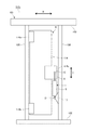
以下、図面に沿って、本発明を木造構造体に適用した実施の形態について説明する。本木造構造体101は、建物を構成する骨組みであり、該木造構造体101が組合せられて木造建物となる。該木造構造体101は、図1ないし図6に示すように、水平方向に並行する2本の横架材102,103、例えば土台材102及び梁材103と、2本の横架材と連続する垂直方向に並行する2本の柱材105,106とを有する。横架材102,103と柱材105,106とは、柱材105,106の上端及び下端に形成されたほぞを、横架材102,103に形成されたほぞ穴に嵌め込むことにより接結されている。該木造構造体による該嵌め込みによる接合は、静止状態にあっては固定(剛)結合であるが、地震等により木造建物が揺れる場合、前記横架材及び柱材は、平行四辺形を保って揺れるので、横架材に対して柱が回動する回り対偶による接合構造として解析される。なお、上記接合部は、L字状の金具で補強されるものも含み、またほぞ及びほぞ穴以外による接合でもよい。また、前記横架材及び柱材は、断面4角形状からなるが、これに限るものではなく、更に木材に限らず、型材からなる軽量鉄骨、更には重量鉄骨等、木造建物に限らず、あらゆる構造物に適用可能である。
Hereinafter, an embodiment in which the present invention is applied to a wooden structure will be described with reference to the drawings. The
前記木造建物における構造体101の制振構造110 1 は、一方の柱材105の上端部105aに連結(A)された第1ブレース材111と、該一方の柱材の下端部105bに連結(B)された第2ブレース材112とを有し、これら両ブレース材111,112の先端部は互いに連結(C)されている。前記両ブレース材111,112は、同じ長さからなり、従って先端部の連結点Cは、他の柱材106の高さ方向中間部、好ましくは中央部に対応するように位置して、2等辺3角形からなる3節リンク(Kブレース構造)を構成している。即ち、該3節リンクは、一方の柱材105と一体構造からなり、上記第1及び第2ブレース材111,112の先端連結部(中間部)Cは、前記2本の横架材102,103の層間変位Xを伝達され、他方の柱材106との間で作動変位Yとして相対移動する伝達手段Uを構成する。なお、上記伝達手段(3節リンク)Uは、上記連結部A,B,Cを理想化したピン接合で図示されているが、柱材105との連結点A,Bは、ビス等で柱材105に固着(剛接合)されてもよく、かつブレース材同士の連結点Cは、接合部に溶接等で固着されてもよい。また、第1及び第2ブレース材111,112は、鋼材からなるのが好ましいが、木材等の他の材料でもよい。この点は、後述するすべての実施の形態においても同様である。
Damping 110 1 of the
上記第1及び第2ブレース材111,112の連結点Cと他方の柱材106との間に油圧ダンパ1が介在している。油圧ダンパ1のピストンロッド6が上記連結点Cにピン結合されており、油圧ダンパ1のシリンダ5が他方の柱材106に固定された連結部材17にピン結合Dされている。
The
地震等により本構造体101に横方向の力が作用して、下横架材(土台)102と上横架材(梁)103との間に相対的変位(層間変位という)Xが生じる。実際には、横架材と柱材との連結がほぞ等による固定で、柱材105,106に曲げ等が作用するが、木材の弾性力により吸収されて、構造体101は、実質的に平行四辺形に変形するとして解析される。従って、下横架材102に対して、上横架材103が右方向(矢印r)に層間変位(X)すると、第1ブレース材111及び第2ブレース材112に圧縮力が作用して、連結点Cが下方向(矢印d)に変位し、油圧ダンパ1を収縮方向に移動する。反対に、下横架材102に対して上横架材103が左方向(矢印l)に層間変位(X)すると、第1及び第2ブレース材111,112に引っ張り力が作用して、連結点Cは、上方向(矢印u)に変位(Y)し、油圧ダンパ1を伸長方向に移動する。
A lateral force acts on the
前記層間変位Xに対する連結点Cの変位Yの割合(Y/X)が、作動効率(作動比率)eと定義され、前記図1に示す制振構造1101にあっては0.3程度となり、層間変位Xに対して連結点Cの変化、従って油圧ダンパ1の作動量は、約1/3となる。前述した特許文献2の実施の形態で示した柱と梁との間に斜めに介在した方杖タイプの油圧ダンパの用い方では、作動効率(作動比率)eが例えば0.2以下等となり、油圧ダンパは、地震エネルギを大きな荷重かつ小さな移動量(ストローク)で吸収することになる。後に詳述する油圧ダンパ1は、地震が弱く、ピストンの移動速度が低い場合、大きい減衰力特性からなる剛体に近い状態となり、地震が強く、ピストンの移動速度が速い場合、減衰力特性の小さい制振状態となるバイリニア特性からなる。上記方杖タイプの油圧ダンパの用い方では、ストロークが小さいため、上記バイリニア特性を建物及び地震にマッチして設計、設置することが難しく、勢い建物に対して多くの油圧ダンパを用いることになる。
The proportion of the displacement Y of the coupling point C with respect to the interlayer displacement X (Y / X) is, operating efficiency is defined as the (working ratio) e, In the damping 110 1 shown in FIG. 1 becomes about 0.3 The change of the connection point C with respect to the interlayer displacement X, that is, the operation amount of the
前記ブレース構造(伝達手段)Uによる制振構造1101は、上述したように作動効率eが0.3程度となり、油圧ダンパ1のストロークYが層間変位Xの1/3程度あって、比較的長いストロークにより適正な上記バイリニア特性を設計することが容易となる。これにより、建物及び予測地震に対応した油圧ダンパの設定及び微妙な制御並びに適正な建物への配置が可能となり、効率的で効果的な建物の制振構造1101を提供することができる。
Said brace (transmission means) damping by U structure 110 1, operating efficiency e as described above becomes about 0.3, stroke Y of the
地震による揺れ(運動)エネルギ(仕事)は、油圧ダンパ1により吸収される。仕事をW、力をF、移動量をΔXとすると、
W=F×ΔX……(1)
構造体101における土台材102に対する梁材103の揺れ量(移動量)は、上記(1)式が適用され、F;変形(移動)に必要な力、ΔX;梁材の移動量(層間変位)となる。
Shaking (kinetic) energy (work) due to the earthquake is absorbed by the
W = F × ΔX (1)
The above equation (1) is applied to the swing amount (movement amount) of the
油圧ダンパ1を伝達手段(ブレース構造)Uを介して設置する場合、作動比率eが考慮され、
e・ΔX=Δd Δd;油圧ダンパ1の変位(移動量)
油圧ダンパの変位に必要な力をFdとすると、
e・F=Fd
油圧ダンパの仕事Wdは、
Wd=Fd・Δd=e2・F・ΔX=e2・W
となる。従って、作動比率eが1に近い程(大きい程)有利であり、伝達手段及び油圧ダンパの配置により作動比率eが1になることが望ましい。
When the
e · ΔX = Δd Δd; displacement (movement amount) of
If the force required for displacement of the hydraulic damper is Fd,
eF = Fd
The work Wd of the hydraulic damper is
Wd = Fd · Δd = e 2 · F · ΔX = e 2 · W
It becomes. Therefore, (enough large) operating ratio e is closer to 1 advantageously der is, working ratio e by the placement of the transmitting means and the hydraulic damper it is desirable to be 1.
図2は、ブレース材に代えて耐力壁材を用いた実施の形態を示す。本実施の形態による制振構造1102は、木造構造体101の一方の柱材105に固定されている耐力壁材114を有する。一方の柱材105の上端部及び下端部にそれぞれビス等で連結部材114a,114bが固定されており、これら連結部材114a,114bに上記耐力壁材114が取付けられている。該耐力壁材114の他側中央部には連結部材114cが取付けられている。油圧ダンパ1のピストンロッド6がピンCにより上記耐力壁材の連結部材114cに連結されていると共に、そのシリンダ5が他方の柱材106に固定された連結部材17にピンDにより連結されている。
FIG. 2 shows an embodiment in which a load-bearing wall material is used instead of the brace material. Damping structure 110 2 according to the present embodiment has a
上記耐力壁材114は、一方が柱材105に一体に固定され、先の実施の形態の2本のブレース材と同様に伝達手段Uとして機能する。従って、本木造構造体の制振構造1102は、先の実施の形態と同様に、作動効率(作動比率)eが0.3程度で層間変位Xを油圧ダンパ1に伝達して該油圧ダンパを移動する。
One of the load-
図3は、ブレース材(リンク部材)自体を油圧ダンパ1に代えた実施の形態を示す。本実施の形態による制振構造1103は、木造構造体101の他方の柱材106の中央部(中間部)に連結部材113がビス等により固定されており、該連結部材113と一方の柱材105における上端部に固定された連結部材105a及び下端部に固定された連結部材105bとの間に、それぞれピンA,B,Cによりリンク部材(111,112)を構成する第1及び第2の油圧ダンパ11,12が取付けられている。
FIG. 3 shows an embodiment in which the brace material (link member) itself is replaced with the
従って、本木造構造体の制振構造1103も、先の実施の形態と同様に、油圧ダンパ11,12自体がブレース材と同様に伝達機構として機能し、作動効率(作動比率)eが概ね0.3程度で層間変位Xを油圧ダンパ11,12に伝達して該油圧ダンパを移動する。
Therefore, even damping 110 3 of the timber structure, as with the previous embodiment, the
図4は、耐力壁材を小型化した実施の形態を示す。図2に示す耐力壁材114は、柱材105より僅かに小さい大型の耐力壁材を用い、木造構造体101の剛性を向上しているが、耐力壁材が大きくかつ重量物からなるため、作業員が一人で取付け作業することが困難となり、コストアップの原因となってしまう。本実施の形態は、耐力壁材115を小型化して、作業員一人での取付け作業を可能とすると共に、木造構造体101に窓等の開閉を設置する場合、窓下等に適用可能となる。
FIG. 4 shows an embodiment in which the load-bearing wall material is reduced in size. Although the load-
一方の柱材105の下部分に、該柱材の長さの1/3程度の耐力壁材115を2個の連結部材115a,115bで固定する。該小型の耐力壁材115の他側上部に連結部材115cを一体に固定し、該連結部材115cと他方の柱材106に固定した連結部材17との間に油圧ダンパ1を介在する。
A load-
従って、本実施の形態による制振構造1104は、先の図2に示すものと同様に、木造構造体101の地震等による層間変位Xを所定作動効率により油圧ダンパ1により吸収する。
Thus, 4 damping structure 110 according to this embodiment, similar to that shown earlier in FIG. 2 will be absorbed by the
図5は、制振構造1105の伝達手段U1,U2にトグル機構を用いた実施の形態を示す。木造構造体の制振構造1105は、一方の柱材105の上端部及び下端部に連結部材105a,105bを一体に取付けると共に、他方の柱材106の中央部(中間部)に連結部材113を一体に取付け、前記連結部材105a,105bと連結部材113との間にそれぞれトグル機構116,117を配設して構成される。各トグル機構116,117は、それぞれ一方の柱材105の連結部材105a,105bにピン結合されたリンク部材116a,117aと、他方の柱材106の連結部材113にピン結合されたリンク部材116b,117bとをそれぞれ先端部をピン結合(G1,G2)して構成される。
Figure 5 shows an embodiment using a toggle mechanism transmitting means U1, U2 of the damping structure 110 5. Damping 110 5 wooden structure, connecting the upper and lower ends of the one
そして、他方の柱材106の上端部及び下端部にそれぞれ連結部材106a,106bが一体に取付けられ、これら連結部材106a,106bと上記各トグル機構116,117の連結ピンG1,G2との間にそれぞれ油圧ダンパ11,12が介在されている。
The connecting
本制振構造1105は、層間変位Xに対して各油圧ダンパ11,12が概ね0.3〜0.5程度の作動効率eにより移動し、木造構造体101の揺れを吸収する。
This damping 110 5 is moved by the
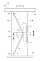
図6は、図1に示すブレース構造に、レバーによる作動効率変更部材を加えた実施の形態を示す。本実施の形態による木造構造体の制振構造1106は、図1と同様に、一方の柱材105に上端部及び下端部に一体に取付けた連結部材105a、105bにピン結合A,Bしたブレース材111,112を有し、これらブレース材111,112の先端は、中間部でレバー部材117にピンCにより連結されている。他方の柱材106の上端部には連結部材119がビス等により一体に固定されており、該連結部材119と、前記レバー部材117のピンCより他方の柱材106側との間にリンク120がピンIにより結合されている。
FIG. 6 shows an embodiment in which an operation efficiency changing member using a lever is added to the brace structure shown in FIG. Damping 110 6 wooden structure according to the present embodiment, as in FIG. 1, and pinned A, B to the connecting
上記レバー部材117の前記ピンCより一方の柱側にはピンJが配置され、該ピンJと、一方の柱材105に一体に取付けられた連結部材17のピンDとの間に油圧ダンパ1が介在している。従って、前記レバー部材117は、その一端側が他方の柱材106にリンク120を介して実質的にピンIにより連結されており、かつブレース材111,112を介してその連結ピンCが一方の柱材105に一体に連結されている。そして、レバー部材117は、作動効率変更部材を構成し、そのレバー比J−C/I−Cにより、ピンJにより連結されている油圧ダンパ1は、ストロークが増大(又は減少)して伝達される。
A pin J is disposed on one column side of the lever C with respect to the pin C, and a
本木造構造体の制振構造1106は、地震等による層間変位Xが、ブレース材111,112によりピンCを上下方向に作動変位として伝播し、該ピンの変位は、レバー部材117によりストロークが増幅されてピンJを介して油圧ダンパ1に伝達される。該油圧ダンパ1は、レバー比が乗じられた作動効率eで移動(ストローク)する。該作動効率eは、上記レバー部材117のレバー比で任意に設定可能であるが、例えば、0.30〜1.20に設定される。これにより、適用する油圧ダンパ1の性能、木造建物の構造等に適合して、例えば油圧ダンパ1の作動ストロークが大きめになるようにレバー比を設定して、油圧ダンパが最適な特性を発揮するにするように調整することが可能となる。
Damping 110 6 of the timber structure, interlayer displacement X caused by an earthquake or the like, to propagate as a working displace the pin C in the vertical direction by the bracing
図7は、図6の実施の形態を具体化して更に一部変更した実施の形態を示す。本実施の形態による木造構造体の制振構造1107も、図6と同様に、一方の柱材105の上端部及び下端部とレバー部材117との間にブレース材111,112がピン結合A,B,C1,C2されている。レバー部材117は、幅広の板材からなり、該レバー部材117の幅広部分に上記2枚のブレース材111,112の連結ピンC1,C2が幅方向に並んで配置されている。これにより、図6の概略図に示すように、1本のピンCに2本のブレース材111,112を連結することによる強度の低下を防止できる。
FIG. 7 shows an embodiment in which the embodiment of FIG. 6 is embodied and further partially modified. Damping 110 7 wooden structure according to the present embodiment is also, similar to FIG. 6, the
レバー部材117の他方の柱材106側の端部と他方の柱材106の連結部材119の間にはリンク120がピンI及びKにより連結されている。該リンク120は、ターンバックルからなり、長さ、従ってレバー部材117の角度を調整し得る。該レバー部材117の先端は、他方の柱材106に取付けられガイド部材121により、レバー部材117の板厚方向の動きが規制されて案内されている。レバー部材117の一方の柱材105側の端部には2個のピンJ1,J2が幅方向に並んで植設されており、これらピンJ1,J2と一方の柱材105に取付けられた連結部材171,172との間に、それぞれ油圧ダンパ11,12が配設されている。即ち、連結ピンC1,C2及びピンJ1,J2は、レバー部材117の長さ方向に直交してかつ比較的狭い間隔で配置されており、レバー部材117のレバー比に関して1個の回動点とみることができる。従って、レバー部材117は、連結ピンC1,C2を支点、ピンIを力点、ピンJ1,J2を作用点として、レバー比は、(J1・J2)−(C1・C2)/(C1・C2−I)=b/aとなる。
A
本木造構造体の制振構造1107は、図6に示す制振構造1106と同様に、地震等による層間変位Xが、ブレース材111,112によりレバー部材117の連結ピンC1,C2に伝播され、該連結ピンC1,C2の作動変位が、レバー部材117のレバー比(b/a)により増幅され(例えば約3倍)、該増幅されたスロトークで2本の油圧ダンパ11,12が作動する。これにより、油圧ダンパ11,12は、1に近い作動効率に基づき、大きな作動ストロークによる適正に調整されたバイリニア特性と、2本の油圧ダンパ11,12による大きな荷重吸収とにより、木造構造体101が制振される。
Damping 110 7 of the timber structure propagation, similar to the damping structure 110 6 shown in FIG. 6, interlayer displacement X caused by an earthquake or the like, the
図8は、図1に示す実施の形態の変形例を示す。本実施の形態による木造構造体の制振構造1108は、図6及び図7に示す実施の形態と同様に、一方の柱材105にピン連結A,Bされたブレース材111,112と、両ブレース材の先端にピン結合C1,C2するレバー部材117を有する。レバー部材117は、一方の端がリンク120及びガイド部材121を介して一方の柱材105に連結しており、他方の端と他方の柱材106との間に1対の油圧ダンパ11,12が介在している。
FIG. 8 shows a modification of the embodiment shown in FIG. Damping 110 8 wooden structure according to the present embodiment, similarly to the embodiment shown in FIGS. 6 and 7, the pin connection A, B have been
連結点C1,C2は、ブレース材111,112により一方の柱材105と一体構造(Kブレース構造)からなり、連結点Iも、リンク120及びガイド部材121により一方の柱材105と一体構造からなり、従ってレバー部材117は、一方の柱材105に一体に構成されている。即ち、レバー部材117は、図6及び図7に示すような作動効率変更部材ではなく、一方の柱材105と一体に移動する補強部材である。
The connection points C1 and C2 have an integral structure (K-brace structure) with the one
従って、本制振構造1108は、図1に示すブレース構造と同様に、地震等による層間変位Xが伝達手段であるブレース構造Uにより連結ピンJ1,J2に、約0.3程度の作動効率eで作動変位Yとして伝播され、油圧ダンパ11,12により吸収される。
Accordingly, the damping structure 110 8, like the brace shown in FIG. 1, the connecting pin J1, J2 by brace U is an interlayer displacement X is transmission means by an earthquake or the like, operating efficiency of about 0.3 is propagated as the working displacement Y in e, it is absorbed by the
図7に示す実施の形態のレバー部材117と図8に示す実施の形態のレバー部材117とは同じもので用いられ、従って連結ピンC1,C2のピン孔117a,117a,117b,117bが長さ方向に2箇所(合計4個)設けられており、該レバー部材117を反転して上記両実施の形態に用いられる。これにより、木造建物の違いにより、油圧ダンパ1の特性を適合して、適宜反転して用いられる。
The
なお、油圧ダンパは、1個でもよく、またレバー部材117のピン孔は、長さ方向2箇所に限らず、更に多数設けて、レバー比を多数に変更してもよい。
The number of hydraulic dampers may be one, and the number of pin holes in the
ついで、図9〜図19に沿って前記油圧ダンパ1について詳細に説明する。なお、前述した木造建物の制振構造において、油圧ダンパを2個用いた場合、油圧ダンパ11,12と表記したが、油圧ダンパの構造は同じなので、油圧ダンパ1として説明する。また、前述した制振構造1101〜1108は、一般化して制振構造110と表記する。
Next, the
上記油圧ダンパ1は、図9及び図10に示すように、シリンダ5及びピストンロッド6を有する。シリンダ5の一端はキャップ部材7により閉塞されており、かつ他端は連結部材9により閉塞されている。ピストンロッド6は、一端が小径部6aとなっており、該小径部6aにピストン10が嵌合している。ピストンロッド6の他端にはボス11及びボルト12からなるピンCを介して例えばブレース材111,112が回動自在に連結している。なお、図1〜図8に示した実施の形態にあっては、例えばブレース構造、耐力壁材、リンク部材、レバー部材等の伝動手段に連結するピンC(C1,C2)として表記されている。前記シリンダ5の他端連結部材9にはボス部15が一体に固定されており、該ボス部15にはボルト16を介して他方の取付け金具17が回動自在に連結されている。なお、取付け金具は、図1,図2,図4,図6,図7,図8にあっては、他方(又は一方)の柱材106(又は105)に連結される取付け金具17(又は171,172)であるが、図3,図5に示す実施の形態にあっては、他方の柱材106に取付けられる取付け金具113と表記されている。
The
前記シリンダ5内の一方側には環状のエンド部材19が嵌合されており、該エンド部材19は、スナップリング20によりシリンダ5に対して軸方向位置が一体となるように規定されている。該エンド部材19の外周面にはOリング21が装着されており、またピストンロッド6が貫通する内周面にもOリング22が装着されており、該エンド部材19は、その軸方向の前後の空間を油密状に区画している。前記シリンダ5内の他方側にはフロート部材23が軸方向に移動自在に嵌合しており、該フロート部材23の外周面にはスライドリング25及びシールリング26が軸方向に並んで装着されている。該フロート部材23は、その軸方向前後の空間を油密状かつ気密状に区画している。
An
前記シリンダ5内におけるエンド部材19とフロート部材23との間の空間には所定粘度のオイルが充填されて、油圧室27を構成している。なお、オイルとは、所定粘度を有する液体を意味し、一般的にはオイルとなるが、狭義のオイルに限定するものではない。前記シリンダ5内におけるフロート部材23と連結部材9との間の空間には所定圧力の窒素ガス等の不活性ガスが封入されて、ガス室29を構成している。シリンダ一端の前記キャップ部材7は、ピストンロッド6を摺動自在に挿通して該ピストンロッドを支持するガイド孔7aを有し、該ガイド孔7aにはピストンロッド6と摺接して該ピストンロッド6に付着した塵埃等を掻取るスクレーパ30が装着されている。シリンダ5内におけるエンド部材19とキャップ部材7との間の空間は空気が出入自在に入る空気室(余裕空隙)31となっている。該空気室31の軸方向間隔は、油圧ダンパ1のストロークより長い。
The space between the
上記エンド部材19の油圧室27側に隣接してバネ受け金具32が配置されており、前記ピストンロッド6の小径部6aに嵌合してバネ受けリング部材33が配置されている。ピストンロッド6の小径部6aの先端にはワッシャ35を介してナット36が螺合されており、バネ受けリング部材33を小径部段差部6bに当接し、かつピストン10の両側に第1及び第2のピストンバルブ371,372を介在して該ピストン10を挟むようにして、上記ナット36により、バネ受けリング部材33、ピストン10及び両ピストンバルブ371,372がピストンロッド6に対して位置決めされている。該ピストン10により、前記油圧室27は、ロッド側油室27aと非ロッド側油室27bに区画されている。ロッド側油室27a内において、上記バネ受け金具32とバネ受けリング部材33との間にコイルスプリング40が縮設されている。
A
上記ピストン10は、図11に詳示するように、両側面10a,10bにピストンロッド6を中心とした環状で凸状の突起45,45が形成されており、該突起45と上記ピストンロッド小径部6aを嵌挿したボス部44との間に、環状の油圧空間46,46が形成されている。なお、上記突起45とボス部44とはピストン両側面10a,10bに対して同じ突出高さ、即ち面一となっている。ピストン10には、一方の側面10aの油圧空間46と他方の側面10bにおける上記突起45の外径側とを連通する複数(3個)の縮み側油路47…と、他方の側面10bの油圧空間46と一方の側面10aにおける上記突起45の外径側とを連通する複数(3個)の伸び側油路49とが形成されており、これら両油路47,49は、同形状及び同数からなり、円周方向に長い矩形状断面からなる。
As shown in detail in FIG. 11, the
上記第1及び第2のピストンバルブ371,372は、環状の板バネからなり、その外周部分が上記環状の突起45に当接するバルブ座板50と、該バルブ座板50を上記環状の突起45に所定付勢力で圧接する皿バネ51とを有する。上記ピストン10の左右の第1及び第2のピストンバルブ371,372は、ピストン10のそれぞれ一方の動きに対して、両油室27a,27bの油路47又は49を通るオイルの移動を規制するチェック弁として機能し、またピストンのそれぞれ他方の動きに対して、両油室27a,27bの油路47又は49を通るオイルの流れを所定特性に制御する。即ち、前記第1及び第2のピストンバルブ371,372は、図15に示すように、それぞれ前記規制される流れと反対方向のオイルの流れに対して、所定値P以下の前記ピストン10の移動速度Vの場合、該移動速度変化に対して前記ピストンを移動する荷重F変化が大きく(S部分)、前記所定値Pより前記ピストン10の移動速度Vが大きい場合、該移動速度変化に対して前記ピストンを移動する荷重F変化が小さい(T部分)減衰力特性を有する。なお、上記所定値Pは、図15にあっては実質的に点で表示されており、該点のように狭い領域で上記急勾配(S部分)と緩勾配(T部分)に切換えられることが好ましいが、図15に鎖線で示すように、ある程度の範囲で滑らかに切換わるものでもよく、上記所定値(変曲点)は、このものも含む概念である。本実施の形態にあっては、第1及び第2のピストンバルブ371,372の各バルブ座板50が2板、皿バネ51が3枚からなるが、これは、上記特性に応じて、その数及びその径方向寸法、板厚は適宜設定される。また、ピストン10の外周面には、所定の油密特性を有すると共にシリンダ5内周面に対して摺接する圧力リング53が装着されている。
Said first and second piston valves 37 1, 37 2 is made of an annular leaf spring, the outer peripheral portion thereof with the
具体的には、図12に示すように、第1及び第2のピストンバルブ371,372は、複数枚のバルブ座板50及び皿バネ51と環状の突起45とからなるチェック弁60を有する。第1及び第2のピストンバルブのいずれか一方、例えば第2のピストンバルブ372は、複数のバルブ座板50の内の上記突起45に接する1枚(50a)に、その外径側から油圧空間46に接する位置まで延びる1個の溝61aからなるオリフィス(バイパス)61が形成されている。該オリフィス(バイパス)61は、バルブ座板50の板厚t(例えば0.15mm)と上記溝61aの幅W(例えば0.5mm)からなる流通面積a(=t×W)を有し、一方の油室27aと、油圧空間46及び油路49を介して他方の油室27bとを連通している。シリンダ5の内径半径をrとした内径断面積A(=πr2≒ピストン面積)に対する上記流通面積aの割合である開口面積比率z(=a/A)が0.004〜0.040の範囲に設定されている。該オリフィス61の開口面積比率zは、上記実施の形態にあっては、第1及び第2のピストンバルブの一方372のみに、かつ複数のバルブ座板50の1枚(50a)のみに、更に該バルブ座板の全周の1箇所のみに形成された小幅の溝61aからなる極小の流通面積からなり、前記特許文献2に示す車両用の緩衝器の油圧ダンパにおけるオリフィスに比して大幅に小さい値であり、このような極小の流通面積からなるオリフィス61により、油圧ダンパ1は上述した急勾配Sからなる減衰力特性150〜600[kN/(m/sec)]を安定して得ることができる。
Specifically, as shown in FIG. 12, the first and second piston valves 37 1, 37 2, a
なお、上記溝61aからなるオリフィス61は、1枚のバルブ座板50aに限らず、例えば第1のピストンバルブ371のバルブ座板50にも設ける等、複数個の溝により形成してもよい。また、オリフィスは、上述したようなバルブ座板に形成すると、高い自由度で極小流通面積が得られて好ましいが、2個の油室を連通するオリフィスであれば、他の構成でもよい。
Incidentally, the
本実施の形態は以上のような構成からなるので、油圧ダンパ1は、前述した木造構造体の制振構造110に設置される。周囲温度の変化が、油圧室27内のオイルの温度に影響して、該オイルが膨張又は収縮する。すると、シリンダ5に摺動自在に支持されてフリーピストンを構成するフロート部材23は、上記オイルの膨張又は収縮による油圧室27の容積変化に応じて、ガス室29内の高圧ガスの付勢力に抗して又は順じて移動する。これにより、周囲温度により油圧室のオイルが体積変化しても、高圧ガスの弾性圧縮により上記フロート部材23が移動して吸収され、エンド部材19のOリング21,22及びフロート部材23のスライドリング25及びシールリング26に過度の圧力を作用することなく、上記各リングからオイルの漏れ及び空気等の吸込みを生じることを防止できる。
Since the present embodiment is configured as described above, the
上記ガス室29には不活性ガスが封入されており、例えシールリング26から該ガスが油圧室27に漏れたとしても、ガスは、不活性ガスからなるので、オイルを酸化することはなく、またシールリングの劣化を防止することができ、油圧ダンパ1の耐久性を、建物に合せて長期化することができる。
An inert gas is sealed in the
油圧室27のロッド側油室27aにピストンロッド6がシリンダ5の外部に突出するように延び、非ロッド側油室27bには上記ピストンロッド6が延びていないので、ピストン10の両側には、上記ピストンロッド6の断面積分の油圧差を生じる。従って、ピストン10に対する両油室27a,27bの面積差によりピストン10は、ピストンロッド6側に移動する方向に偏倚する力が作用するが、本実施の形態にあっては、ロッド側油室27aに配置されたスプリング40の付勢力がピストン10に作用し、該ピストン10は、該スプリング付勢力と上記面積差による偏倚力がバランスした位置である、スプリング40の全圧縮位置とフロート部材23との中間位置に保持される。
The
上記スプリング40の付勢力に基づく油圧室27内の油圧がフロート部材23に作用するが、ガス室29内には高圧ガスが封入されており、上記フロート部材23は、油圧室27側の油圧とガス室29側のガス圧とがバランスして所定位置に保持されている。
The hydraulic pressure in the
これにより、油圧ダンパ1は、外力を加えていない自然状態にあっては、予め設定された所定長さにあり、該所定長さの油圧ダンパ1が、前述したように木造構造体の制振構造110として取付けられる。この状態では、ピストン10が油圧室27のストローク可能範囲の略々中央に位置している。
Thus, the
地震により建物に揺れを生じる場合、油圧ダンパ1は、伸縮してストローク範囲の略々中央に位置するピストン10が図9の左右方向に移動する力を受ける。ピストン10が油圧室27を右方向(縮み方向)に移動しようとする場合、非ロッド側油室27bのオイルが縮み側油路47を通って左油圧空間46に流れて、第1のピストンバルブ371のバルブ座板50を撓ましてロッド側油室27aに流れる方向の力が作用し、反対に、ピストン10が油圧室27を左方向(伸び方向)に移動しようとする場合、ロッド側油室27aのオイルが伸び側油路49を通って右油圧空間46に流れて、第2のピストンバルブ372のバルブ座板50を撓まして非ロッド側油室27bに流れる方向の力が作用する。この際、ピストン10の縮み側移動では、第2のピストンバルブ372のバルブ座板50が環状の突起45に当接して、非ロッド側油室27bから右油圧空間46及び伸び側油路49を通ってロッド側油室27aに流れるオイルの流れが阻止され、ピストン10の伸び側移動では、第1のピストンバルブ371のバルブ座板50が環状の突起45に当接して、ロッド側油室27aから左油圧空間46及び縮み側油路47を通って非ロッド側油室27bに流れるオイルの流れが阻止される。
When the building shakes due to the earthquake, the
地震が弱く建物の揺れが小さい場合、油圧ダンパ1に作用する伸縮方向の力も小さくかつ弱い。この場合、ピストン10が油圧室27内で移動しようとする力も弱く、その速度も遅い。油圧ダンパ1が収縮する方向、即ちピストン10が非ロッド側油室27bに向って移動する場合、非ロッド側油室27b内のオイルが縮み側油路47を通って左油圧空間46に流れようとするが、ピストン10を移動する力も弱くかつ遅いので、左油圧空間46に作用する油圧上昇も小さい。従って、第1のピストンバルブ371は、皿バネ51の付勢力によりバルブ座板50が環状の突起45に略々当接した閉じ位置に保持される。同様に、油圧ダンパ1が伸長する方向、即ちピストン10がロッド側油室27aに向って移動する場合、ロッド側油室27aのオイルが伸び側油路49を通って右油圧空間46に流れようとするが、該右油圧空間46の油圧も小さく、第2のピストンバルブ372は、バルブ座板50が環状の突起45に略々当接した閉じ位置に保持される。
When the earthquake is weak and the shaking of the building is small, the force in the expansion and contraction direction acting on the
従って、地震の規模が比較的小さく、建物に作用するエネルギが小さい場合、油圧ダンパ1は、その収縮及び伸長の両方向において非ロッド側油室27b及びロッド側油室27aに流れようとするオイルの流れが前記オリフィス61により制限された減衰力特性の大きい状態にあり、油圧ダンパ1の伸縮移動は、大きな抵抗力を受ける。即ち、ピストン10の移動速度が遅い場合、図15のS部分に示すように、両油室27a,27bのオイルの流通量は、極小の流通面積からなるオリフィス61による僅かな量であり、大きな荷重(抵抗力)が作用し、油圧ダンパ1は、ピストン速度Vに対する荷重Fの勾配が大きな剛体に近い状態となる。これにより、地震規模が小さい場合又は道路を車両が通過する振動の場合等、振動エネルギが小さく、建物の揺れが比較的小さい場合、油圧ダンパ1からなる制振構造110は、建物に対して剛体に近いブレース材、耐力壁として機能し、建物の揺れを抑えると共に、建物の強度を向上する。この際、油圧ダンパ1の取付け部分に集中荷重が作用するとしても、振動エネルギは比較的小さいので、該取付け部分が破損することはない。また、両油室27a,27bの間を流れるオイルは、バルブ座板50と環状のオリフィス61の狭い通路を大きな抵抗を受けながら流れるので、熱に変換され、ヒステリシスとなって建物の揺れエネルギを有効に吸収する。このように、比較的高い頻度で発生する小さな振動エネルギに対しては、建物は、上記減衰力特性の高い油圧ダンパにより建物の揺れは抑えられ、建物の居住性等の構造物の品質を向上することができる。
Therefore, when the magnitude of the earthquake is relatively small and the energy acting on the building is small, the
地震規模が大きく、建物の揺れが大きい場合、油圧ダンパ1に作用する伸縮方向の力も大きくなると共に、そのストロークも大きくなりかつ速度も速くなる。この状態では、ピストン10は大きなストロークでかつ速く移動し、ピストン10が右方向に移動する場合、非ロッド側油室27bから、縮み側油路47を通って左油圧空間46に流れ込むオイル油圧が高くなり、第1のピストンバルブ371のバルブ座板50は、図13に示すように、該座板自体のバネ力及びバックアップとしての皿バネ51の付勢力に抗してその外周部分が環状の突起45から離れる方向に撓む。同様に、ピストン10が左方向に移動する場合、ロッド側油室27aから、伸び側油路49を通って右油圧空間46に流れ込むオイルの油圧が高くなり、第2のピストンバルブ372のバルブ座板50は、環状の突起45から離れる方向に撓む。
When the magnitude of the earthquake is large and the vibration of the building is large, the force acting on the
これにより、第1及び第2のピストンバルブ371,372は、図13に示すように、バルブ座板50と環状の突起45との間に流路M,Nが形成され、該流路M,Nを通って両油室27a,27bにオイルが流れることにより、図15のT部分に示すように、速度Vに対する荷重Fの勾配が低い減衰力特性の低い状態となり、油圧ダンパ1は、低い抵抗力により伸縮する。従って、大きな地震に際しては、油圧ダンパ1が、比較的低い減衰力特性により建物の揺れを制振し、地震エネルギを吸収する。この際、図13に示すように、バルブ座板50の外径部は、環状の突起45とその全周において離れ、該周長の長い環状の突起45との間に比較的広い面積からなる上記流路M,Nが一気に形成される。これにより、図15に示すように、油圧ダンパの減衰力特性は、所定値(変曲点)Pにおいて急勾配(S)から緩勾配(T)に瞬時に切換えられる。
Thus, the first and
この状態では、油圧ダンパ1は、伸縮しつつ制振するので、取付け部分に過度に大きな集中荷重が作用することがなく、該取付け部分又は該取付け部分の柱材105,106及びブレース材等が破壊されることを減少する。また、地震エネルギは、上部流路M,Nを絞られつつ流れる比較的大量のオイルの流れにより熱に変換されて吸収される。また、上記地震により建物が塑性変形領域まで変形したとしても、地震が終わった状態で、油圧ダンパ1は、スプリング40及びガス室29のガス圧がバランスすると共にピストンロッド6の面積差による両油室27a,27bの初期位置に戻るように付勢されており、上記塑性変形まで変形した建物も、上記油圧ダンパ1のストローク中央位置への付勢により元の状態(初期姿勢)に戻される。これにより、頻度は少ないが、大きな地震が発生した場合、建物は、本制振構造110により有効に制振され、建物の破壊を防止して耐震性を向上することができる。
In this state, the
更に、例え木造建物が変形しても、油圧ダンパ1は、元の状態に戻るように付勢されるので、木造建物自体の復元力と相俟って、構造体101からなる建物は、徐々に元の状態に戻される。
Further, even if the wooden building is deformed, the
上記油圧ダンパ1は、シリンダ5からピストンロッド6が突出する側に空気室(余裕空隙)31が設けられており、該空気室31部分のピストンロッド6は、キャップ部材7のスクレーパ30により塵埃、錆、水等が除去されたクリーンな状態にある。従って、上記地震により油圧ダンパ1が伸縮して、ピストンロッド6がエンド部材19の貫通孔を摺接しても、該摺接部分は、上記クリーンな状態にある部分であり、上記摺接に際してピストンロッドに付着した塵埃等がエンド部材19のシール(Oリング)22を傷付けたり、また該塵埃、水等が油圧室27内に浸入することを防止できる。
The
なお、チェック弁である第1及び第2のピストンバルブ371,372にオリフィス61を設けないと、ピストンバルブが閉じ位置にある場合、ピストン10及びピストンバルブ371,372の漏れ(オイルリーク)に起因する急勾配(S部分)で荷重Fが増加し、高い減衰力特性を有する。該急勾配(S部分)からなる減衰力特性は、800[kN/(m/sec)]程度となる。
Note that when not provided the first and
上記オイルリークによる減衰力特性は、バルブ座板50と環状の突起45との密着精度及びピストン10とシリンダ5との嵌合精度等との機械的精度に影響され、高い精度で上記減衰力特性を安定することが難しい。また、地震等の建物の揺れによる油圧ダンパ1の伸縮は、圧縮側、伸長側に比較的速い周期で切換わり、前記所定値(変曲点)Pまでは、減衰力は作動量に比例して略々直線的に上昇し(急勾配S部分)、リリーフ圧(P)に達してからは、略々一定の減衰力(緩勾配T部分)に保持される。油圧ダンパ1は、前記圧縮側又は伸長側に切換わる時点で瞬間的に作動を停止するが、上記オイルリークを最小限に設定すると、油室27a,27bに残圧が生じる。この結果、上記油圧ダンパ1が逆方向に作動開始しても、上記残圧が解消するまでは、ピストン10の作動方向に抵抗する力は発生せず、減衰力の発生に遅れを生じる。該減衰力の立ち上り遅れは、ヒステリシス面積にも影響を与え、エネルギ吸収量は小さくなる。
The damping force characteristic due to the oil leak is affected by mechanical accuracy such as the close contact accuracy between the
また、油圧ダンパ1は、前述した伝達手段Uにより作動効率eが大きくなるように変更した制振構造110に用いられるので、上記オリフィス61を設けない場合、地震初期の移動速度が所定値P以下の状態では、油圧ダンパの横揺れに対する抗力が大き過ぎ、油圧ダンパ1の減衰力の立ち上りが遅れ傾向となるが、小流通面積aのオリフィス61を有するので、地震初期による油圧ダンパの立ち上り遅れを防止し、かつオリフィス61により油圧ダンパ1が所定ストロークした後、地震による構造体101の大きくかつ移動の速い層間変位に対して、油圧ダンパ1は、速い応答性で比較的大きくストロークする。これにより、上述した伝達手段による作動効率eに適合したストローク及び抗力(荷重)により油圧ダンパ1は、高い効率で有効に建物を制振する。
Further, since the
鋭意研究した結果、チェック弁であるピストンバルブが閉じ位置にある場合(急勾配部分S)における移動速度に対する荷重変化(勾配)が、150〜600[kN/(m/sec)]にある場合、上述した効果が得られる知見を得た。即ち、上記勾配が150[kN/(m/sec)]以下であると、小さな地震等による建物の揺れエネルギを吸収して、建物の揺れを有効に抑えることができず、上記勾配が600[kN/(m/sec)]以上であると、上記残圧が生じて、有効に振動エネルギを吸収することができない。 As a result of intensive research, when the load change (gradient) with respect to the moving speed when the piston valve serving as the check valve is in the closed position (the steep slope portion S) is 150 to 600 [kN / (m / sec)], The knowledge which can obtain the above-mentioned effect was obtained. That is, if the gradient is 150 [kN / (m / sec)] or less, the energy of shaking of the building due to a small earthquake or the like cannot be absorbed, and the shaking of the building cannot be effectively suppressed. When the pressure is equal to or more than kN / (m / sec)], the residual pressure is generated, and vibration energy cannot be effectively absorbed.
例えば、第1及び第2のピストンバルブ371,372の1枚のバルブ座板50aにそれぞれ溝61aを形成して、2個の溝からなるオリフィス61は、流通面積aが0.15[mm2]となる。この場合の急勾配Sでの減衰力特性(等価剛性)は、350〜600[kN/(m/sec)]となり、該減衰力特性の範囲では、等価剛性も比較的大きく、かつ加速度(衝撃)吸収性もあり、大変形〜微小変形の大きな揺れ領域に対して、バランスよく制振効果を期待できる。
For example, to form the first and
上記溝61aが合計4個からなるオリフィス61は、流通面積aが0.30[mm2]となり、この場合の急勾配Sでの減衰力特性(等価剛性)は、150〜350[kN/(m/sec)]となる。該減衰力特性の範囲では、加速度(衝撃)吸収性が高くなり、微小変形領域において有効に機能し、例えばトラックの道路走行に起因する生活振動等に対して大きな制振効果が期待できる。
The
なお、溝61aの数は、2個、4個に限らず、1個、3個又はそれ以上でもよく、減衰力特性が150〜800[kN/(m/sec)]の範囲となる間で、適宜設定することができる。
The number of the
従って、上記勾配Sでの減衰力特性は、150〜600[kN/(m/sec)]の範囲で上述した建物の制振構造として有効に機能し、かつ残圧による応答遅れを生じることがなく、建物の制振構造として好ましく、更に300〜600[kN/(m/sec)]の範囲において、等価剛性と加速度(衝撃)吸収性のバランスのとれた大きな範囲で制振効果が期待できる。 Therefore, the damping force characteristic at the above-described gradient S effectively functions as the above-described building vibration damping structure in the range of 150 to 600 [kN / (m / sec)], and may cause a response delay due to residual pressure. Therefore, it is preferable as a vibration damping structure of a building. Further, in the range of 300 to 600 [kN / (m / sec)], a vibration damping effect can be expected in a large range in which equivalent rigidity and acceleration (shock) absorption are well balanced. .
図14に沿って、ピストンバルブ375,376を一部変更した実施の形態について説明する。なお、先の実施の形態と同様な部分は、同一符号を付して説明を省略する。ピストン10’は、ピストンロッド小径部6aを嵌挿するボス部44と環状の突起45を有する。ピストンの両側面10’a,10’bにおける上記突起45の突出高さHが、ボス部44の突出高さhに比して高く構成される。第1及び第2のピストンバルブ375,376は、ピストン10’の両側面において、ワッシャ35、バネ受けリング部材33等を介して、ピストンロッド段差部6bとの間でナット36を締付けることにより取付けられる。
Along the 14, the
バルブ座板50及び皿バネ51は、上記ナット36の締付けにより、その中心部分がボス部44に接触するように、かつバルブ座板50の外周部が上記突起45に当接するように押さえられる。上記突起45とボス部44の突出高さ(H>h)の差により、板バネからなるバルブ座板50は、撓んでその外周部が突起45に接触する方向の所定予荷重が付与される。
By tightening the
これにより、ピストン10’の移動速度が所定値以下で、油圧空間46に所定油圧が作用しないと、上記バルブ座板50は、上記所定予荷重により閉塞位置に保持される。従って、油圧ダンパ1の減衰力特性は、急勾配部分(S)の勾配が急になり、所定値Pが高くなる。これにより、弱い地震等に対しては、油圧ダンパ1は剛体に近くなり、建物の揺れを抑えることができ、かつピストン移動速度Vが所定値P以上となる所定規模以上の強い地震に対しては、一気に緩勾配Tに切換わって、建物を制振してその破壊を抑えることができる。
Thus, when the moving speed of the piston 10 'is equal to or less than the predetermined value and the predetermined hydraulic pressure does not act on the
図14に示すように、ボス部44とバルブ座板50との間に、所定枚数(本実施の形態では1枚)の間座55を介在して、第1及び第2のピストンバルブ375,376が取付けられる。該間座55の枚数又は板厚を調節することにより、上記バルブ座板50に作用する所定予荷重を調整することができる。これにより、木造建物の構造、建物の強度、規模、振動特性等に対応して上記予荷重が調整され、適正な油圧ダンパ1を選択することにより、容易に建物に対応した油圧ダンパを適用することが可能となる。
As shown in FIG. 14, between the
図16〜図19は、オリフィス(バイパス)を有するピストンバルブを備えた油圧ダンパの減衰力特性を示す。なお、シリンダの内径断面積Aは、1661.90[mm2]であり、横軸はピストンの移動速度[m/sec]、縦軸は荷重[kN]である。図16,図17は、オリフィス(バイパス)の流通面積aが0.30[mm2]であり、図16は油圧ダンパの縮み側の移動、図17は、伸び側の移動を示す。図18,図19は、オリフィス(バイパス)の流通面積aが0.15[mm2]であり、図18が、油圧ダンパの縮み側の移動、図19は伸び側の移動を示す。 16 to 19 show damping force characteristics of a hydraulic damper provided with a piston valve having an orifice (bypass). Note that the inner diameter cross-sectional area A of the cylinder is 1661.90 [mm 2 ], the horizontal axis is the moving speed [m / sec] of the piston, and the vertical axis is the load [kN]. 16 and 17 show that the flow area a of the orifice (bypass) is 0.30 [mm 2 ], FIG. 16 shows the movement of the hydraulic damper on the contraction side, and FIG. 17 shows the movement on the extension side. 18 and 19 show the orifice (bypass) flow area a of 0.15 [mm 2 ]. FIG. 18 shows the movement of the hydraulic damper on the contraction side, and FIG. 19 shows the movement on the extension side.
なお、前記ピストンバルブの構造は、環状の突起45及びバルブ座板50からなるものに限らず、付勢された弁構造からなるもの等、上述した減衰力特性を備えるものであれば、他の構造でもよい。また、上記実施の形態は、ピストンロッド6は、ロッド側油室27aのみに貫通しているが、非ロッド側油室27bにも貫通してフロート部材23に支持されるものでもよい。この場合、スプリング40は、必ずしも必要としない。
The structure of the piston valve is not limited to the structure including the
1 油圧ダンパ
5 シリンダ
6 ピストンロッド
7 キャップ部材
9 シリンダの端部(連結部材)
10,10’ ピストン
10a,10’a 側面
10b,10’b 側面
19 エンド部材
23 フロート部材
27 油圧室
27a 一方の油室(ロッド側油室)
27b 他方の油室(非ロッド側油室)
29 ガス室
371,375 第1のピストンバルブ
372,376 第2のピストンバルブ
40 スプリング
44 ボス部
45 突起
46 油圧空間
47,49 (縮み側)油路、(伸び側)油路
50 バルブ座板
60 チェック弁
61 オリフィス
61a 溝
z 開口面積比率
101 構造体
102,103 横架材
105,106 柱材
110,1101〜1108 制振構造
111,112 ブレース材
114,115 耐力壁材
117 レバー部材
C,C1,C2 中間部(連結ピン)
U,U1,U2 伝達手段
10, 10 '
27b The other oil chamber (non-rod side oil chamber)
29
U, U1, U2 Transmission means
Claims (10)
前記構造体内に配置され、前記2本の横架材の層間変位を作動変位として伝達する伝達手段と、
前記伝達手段の作動変位を吸収する油圧ダンパと、を備え、
前記油圧ダンパは、シリンダ内にオイルを充填した油圧室を1個のピストンにより2個の油室に区画し、前記シリンダに少なくとも軸方向に一体のエンド部材と、前記シリンダに軸方向に移動自在なフロート部材との間で前記油圧室を形成してなり、
前記シリンダの端部の閉塞部と前記フロート部材との間に、前記油圧室から前記フロート部材に作用する油圧に対向する所定圧の不活性ガスが封入されているガス室を形成し、
前記ピストン部分に、前記2個の油室の一方から他方の油室へのオイルの流れを規制する第1のピストンバルブと、前記他方の油室から一方の油室へのオイルの流れを規制する第2のピストンバルブと、前記2個の油室を連通するオリフィスと、を設け、
前記油圧ダンパは、前記第1及び第2のピストンバルブがそれぞれ前記規制される流れと反対方向のオイルの流れに対して、前記シリンダに対する前記ピストンの移動速度が所定値以下の状態では閉じ位置にあって前記オイルの流れを前記オリフィスにより制限し、移動速度に対する荷重変化が急勾配からなり、前記ピストンの移動速度が前記所定値より速い状態では開かれて前記オイルの流れを許容し、移動速度に対する荷重変化が小さい緩勾配からなる減衰力特性を有し、
前記オリフィスは、前記シリンダの内径断面積に対する該オリフィスの流通面積の比である開口面積比率が0.004〜0.040である、
ことを特徴とする建物の制振構造。 A vibration damping structure for a building having a structure composed of two parallel pillar members and two parallel transverse members joined to upper and lower ends of these two pillar members,
A transmission unit disposed in the structure, for transmitting an interlayer displacement of the two transverse members as an operation displacement;
A hydraulic damper that absorbs the operating displacement of the transmission means ,
In the hydraulic damper, a hydraulic chamber filled with oil in a cylinder is divided into two oil chambers by one piston, and an end member integrated at least in the axial direction with the cylinder and freely movable in the cylinder in the axial direction. The hydraulic chamber is formed between the floating member and a floating member,
A gas chamber in which an inert gas having a predetermined pressure opposite to a hydraulic pressure acting on the float member from the hydraulic chamber is sealed between the closed portion at the end of the cylinder and the float member,
A first piston valve for regulating the flow of oil from one of the two oil chambers to the other oil chamber, and regulating a flow of oil from the other oil chamber to the one oil chamber; A second piston valve, and an orifice communicating the two oil chambers,
The hydraulic damper moves to the closed position when the moving speed of the piston with respect to the cylinder is equal to or less than a predetermined value with respect to the oil flow in the opposite direction to the flow in which the first and second piston valves are respectively regulated. The oil flow is restricted by the orifice, and the load change with respect to the moving speed has a steep gradient. When the moving speed of the piston is higher than the predetermined value, the piston is opened to allow the oil flow, and the moving speed is adjusted. Has a damping force characteristic consisting of a gentle gradient with a small load change to
The orifice has an opening area ratio of 0.004 to 0.040, which is a ratio of a flow area of the orifice to an inner sectional area of the cylinder.
A vibration control structure of a building characterized by the following.
請求項1記載の建物の制振構造。 The transmitting means is connected at at least two places of different heights in one of the two pillars, and is a middle part in a height direction of a connecting portion of the one pillar on the other pillar side. Transmitted to the portion as the working displacement,
The building vibration control structure according to claim 1.
前記油圧ダンパは、前記ブレース構造の中間部と前記他方の柱材との間に介在されてなる、
請求項2記載の建物の制振構造。 The transmission means is a brace structure connected to the upper end and the lower end of the one pillar, respectively, and connected to each other at the intermediate part.
The hydraulic damper is interposed between an intermediate portion of the brace structure and the other column member,
The structure for damping a building according to claim 2.
請求項2記載の建物の制振構造。 The transmission means is a load-bearing wall material fixed to the one column material, and the hydraulic damper is interposed between the other column material side of the load-bearing wall material and the other column material,
The structure for damping a building according to claim 2.
請求項2記載の建物の制振構造。 The hydraulic damper is connected between an end of the one pillar and an intermediate part of the other pillar,
The structure for damping a building according to claim 2.
前記油圧ダンパは、前記トッグル機構の連結ピンと前記他方の柱材との間に介在してなる、
請求項2記載の建物の制振構造。 The transmission means is a toggle mechanism connected between an end of the one pillar and an intermediate part of the other pillar,
The hydraulic damper is interposed between the connection pin of the toggle mechanism and the other column member,
The structure for damping a building according to claim 2.
前記油圧ダンパは、前記レバー部材の他端と前記一方の柱材の間に介在され、
前記レバー部材は、前記第1及び第2ブレース材の連結点を支点とし、前記一端の連結点を力点とし、前記他端の連結点を作用点としたレバー比により、前記力点に作用する変位を前記作用点から前記油圧ダンパに変更して伝達してなる、
請求項2記載の建物の制振構造。 The transmission means includes first and second brace members each having one end connected to an upper end portion and a lower end portion of the one column member, and one end connected to an intermediate portion of the other column member; And a lever member to which the other end of the second brace material is connected,
The hydraulic damper is interposed between the other end of the lever member and the one pillar,
The lever member has a connection point between the first and second brace members as a fulcrum, a connection point at the one end as a power point, and a displacement acting on the power point by a lever ratio using the connection point at the other end as an operation point. From the point of action to the hydraulic damper and transmitted.
The structure for damping a building according to claim 2.
請求項1ないし7のいずれか1項記載の建物の制振構造。 In the hydraulic damper, a load change with respect to the moving speed in a state of being equal to or less than the predetermined value is 150 to 600 [kN / (m / sec)].
A vibration damping structure for a building according to any one of claims 1 to 7 .
請求項1ないし8のいずれか1項記載の建物の制振装置。 In the hydraulic damper, a piston rod from the piston extends from the piston through only one of the two oil chambers, and is contracted between the end member and the piston. A spring is arranged in the one oil chamber,
The building vibration damping device according to claim 1 .
前記バルブ座板は、複数枚からなり、該複数枚のバルブ座板の少なくとも1枚に、外径側から切込まれた少なくとも1個の溝が形成され、該溝が前記環状の突起の内径側と外径側とを連通して前記オリフィスを形成してなる、
請求項1ないし9のいずれか1項記載の建物の制振装置。 The first and second piston valves are formed on both side surfaces of the piston, and are provided with annular protrusions having a circumference centered on a central axis of the hydraulic damper, and an outer peripheral portion abutting the protrusions. A biased flexible valve seat plate, and an oil passage that communicates both side surfaces of the piston on the outer diameter side and the inner diameter side of the projection, respectively,
The valve seat plate is composed of a plurality of plates, and at least one groove cut from an outer diameter side is formed in at least one of the plurality of valve seat plates, and the groove has an inner diameter of the annular projection. The orifice is formed by communicating the side with the outer diameter side,
Vibration damping device of a building according to any one of claims 1 to 9.
Priority Applications (1)
| Application Number | Priority Date | Filing Date | Title |
|---|---|---|---|
| JP2015177429A JP6626671B2 (en) | 2015-09-09 | 2015-09-09 | Building damping structure |
Applications Claiming Priority (1)
| Application Number | Priority Date | Filing Date | Title |
|---|---|---|---|
| JP2015177429A JP6626671B2 (en) | 2015-09-09 | 2015-09-09 | Building damping structure |
Publications (3)
| Publication Number | Publication Date |
|---|---|
| JP2017053135A JP2017053135A (en) | 2017-03-16 |
| JP2017053135A5 JP2017053135A5 (en) | 2019-01-31 |
| JP6626671B2 true JP6626671B2 (en) | 2019-12-25 |
Family
ID=58320504
Family Applications (1)
| Application Number | Title | Priority Date | Filing Date |
|---|---|---|---|
| JP2015177429A Active JP6626671B2 (en) | 2015-09-09 | 2015-09-09 | Building damping structure |
Country Status (1)
| Country | Link |
|---|---|
| JP (1) | JP6626671B2 (en) |
Families Citing this family (7)
| Publication number | Priority date | Publication date | Assignee | Title |
|---|---|---|---|---|
| CN107700693A (en) * | 2017-09-27 | 2018-02-16 | 中船第九设计研究院工程有限公司 | A kind of damper system with stroke amplification |
| CN109440960A (en) * | 2018-12-23 | 2019-03-08 | 宋和平 | It is a kind of can be to the energy-dissipating support system that damper displacement amplifies |
| CN110106778B (en) * | 2019-06-18 | 2023-11-03 | 重庆三峡学院 | Bridge structure prevents district power consumption strutting arrangement that bends |
| JP7370199B2 (en) * | 2019-07-25 | 2023-10-27 | 株式会社Nttファシリティーズ | Vibration damping reinforcement system |
| CN112079269A (en) * | 2020-09-06 | 2020-12-15 | 江苏巨麦机床科技有限公司 | High-efficiency hoisting device for machine tool equipment |
| CN113293877B (en) * | 2021-05-11 | 2022-09-20 | 昆明学院 | Be applied to universal damping subassembly of anti-wind tensile on shock insulation layer |
| CN113982350B (en) * | 2021-11-18 | 2023-05-05 | 广东科学技术职业学院 | Civil engineering damping device and use method thereof |
Family Cites Families (11)
| Publication number | Priority date | Publication date | Assignee | Title |
|---|---|---|---|---|
| US5934028A (en) * | 1996-08-08 | 1999-08-10 | Tayco Developments, Inc. | Toggle linkage seismic isolation structure |
| JP3538289B2 (en) * | 1996-12-06 | 2004-06-14 | 辰治 石丸 | Vibration control device using toggle mechanism |
| JPH10227148A (en) * | 1997-02-17 | 1998-08-25 | Tokico Ltd | Vibration-damping wall panel |
| JP4055060B2 (en) * | 2002-09-30 | 2008-03-05 | 株式会社日立製作所 | Hydraulic shock absorber |
| JP3796216B2 (en) * | 2002-12-24 | 2006-07-12 | 日立機材株式会社 | Installation method of hydraulic damper |
| JP4139901B2 (en) * | 2005-01-28 | 2008-08-27 | 国立大学法人東京工業大学 | Damping structure of wooden building and damping method of wooden building |
| JP2011157728A (en) * | 2010-02-01 | 2011-08-18 | Bando Chemical Industries Ltd | Damper and wood construction using the same |
| JP2014095406A (en) * | 2012-11-08 | 2014-05-22 | Shimizu Corp | Vibration reduction device |
| JP2014101638A (en) * | 2012-11-16 | 2014-06-05 | Asahi Kasei Homes Co | Vibration control structure |
| JP6274726B2 (en) * | 2013-01-24 | 2018-02-07 | スターツCam株式会社 | Seismic control building and design method of seismic control building |
| JP5620596B1 (en) * | 2014-02-19 | 2014-11-05 | 千博産業株式会社 | Structure damping device |
-
2015
- 2015-09-09 JP JP2015177429A patent/JP6626671B2/en active Active
Also Published As
| Publication number | Publication date |
|---|---|
| JP2017053135A (en) | 2017-03-16 |
Similar Documents
| Publication | Publication Date | Title |
|---|---|---|
| JP6626671B2 (en) | Building damping structure | |
| US9540807B2 (en) | Structure vibration control device | |
| JP5620596B1 (en) | Structure damping device | |
| JP5515100B2 (en) | Damping device for beam column structure | |
| JP5763788B2 (en) | Displacement amplification type vibration control system and its construction method | |
| JP2017053135A5 (en) | ||
| JP2014156964A (en) | Friction type seismic tie for vibration control over boiler | |
| JP2014066300A (en) | Vibration damper for structure | |
| KR20090126428A (en) | Toggled damper using leverage | |
| JP4182200B2 (en) | Hydraulic damper | |
| JP2014159689A (en) | Vibration control device and building with the same | |
| JPH1136657A (en) | Base isolation device | |
| JP4432208B2 (en) | Damper and building using it | |
| JP5356563B2 (en) | Shock absorber filled with viscoelastic fluid | |
| JP5874336B2 (en) | Vibration control device | |
| JP6779480B2 (en) | Vibration control device | |
| JP2008144362A (en) | Vibration control structure and vibration control method for building | |
| JP2017053364A (en) | Stopper and damping device | |
| JP6567267B2 (en) | Structure damping device | |
| JPH11140977A (en) | Rotational rigidity adjustment type column-beam connection structure and earthquake-resisting building | |
| JP2005248989A (en) | Vibration control damper | |
| JP2003148545A (en) | Hydraulic damping device | |
| JP2003041798A (en) | Vibration control unit, vibration control construction method and structure using this unit | |
| JP5214371B2 (en) | Structure | |
| KR102283043B1 (en) | Plate type damper to reduce residual deformation |
Legal Events
| Date | Code | Title | Description |
|---|---|---|---|
| A621 | Written request for application examination |
Free format text: JAPANESE INTERMEDIATE CODE: A621 Effective date: 20180625 |
|
| A521 | Request for written amendment filed |
Free format text: JAPANESE INTERMEDIATE CODE: A523 Effective date: 20181211 |
|
| A977 | Report on retrieval |
Free format text: JAPANESE INTERMEDIATE CODE: A971007 Effective date: 20190425 |
|
| A131 | Notification of reasons for refusal |
Free format text: JAPANESE INTERMEDIATE CODE: A131 Effective date: 20190521 |
|
| A521 | Request for written amendment filed |
Free format text: JAPANESE INTERMEDIATE CODE: A523 Effective date: 20190718 |
|
| TRDD | Decision of grant or rejection written | ||
| A01 | Written decision to grant a patent or to grant a registration (utility model) |
Free format text: JAPANESE INTERMEDIATE CODE: A01 Effective date: 20191126 |
|
| A61 | First payment of annual fees (during grant procedure) |
Free format text: JAPANESE INTERMEDIATE CODE: A61 Effective date: 20191202 |
|
| R150 | Certificate of patent or registration of utility model |
Ref document number: 6626671 Country of ref document: JP Free format text: JAPANESE INTERMEDIATE CODE: R150 |
|
| R250 | Receipt of annual fees |
Free format text: JAPANESE INTERMEDIATE CODE: R250 |
|
| S111 | Request for change of ownership or part of ownership |
Free format text: JAPANESE INTERMEDIATE CODE: R313113 |
|
| R350 | Written notification of registration of transfer |
Free format text: JAPANESE INTERMEDIATE CODE: R350 |
|
| R250 | Receipt of annual fees |
Free format text: JAPANESE INTERMEDIATE CODE: R250 |