JP6621249B2 - Portable worktable - Google Patents
Portable worktable Download PDFInfo
- Publication number
- JP6621249B2 JP6621249B2 JP2015108727A JP2015108727A JP6621249B2 JP 6621249 B2 JP6621249 B2 JP 6621249B2 JP 2015108727 A JP2015108727 A JP 2015108727A JP 2015108727 A JP2015108727 A JP 2015108727A JP 6621249 B2 JP6621249 B2 JP 6621249B2
- Authority
- JP
- Japan
- Prior art keywords
- beam member
- side beam
- short
- long
- pair
- Prior art date
- Legal status (The legal status is an assumption and is not a legal conclusion. Google has not performed a legal analysis and makes no representation as to the accuracy of the status listed.)
- Active
Links
- 230000002093 peripheral effect Effects 0.000 description 7
- 229910000838 Al alloy Inorganic materials 0.000 description 2
- 239000011347 resin Substances 0.000 description 2
- 229920005989 resin Polymers 0.000 description 2
- 238000013459 approach Methods 0.000 description 1
- 238000010276 construction Methods 0.000 description 1
- 238000009429 electrical wiring Methods 0.000 description 1
- 229910052751 metal Inorganic materials 0.000 description 1
- 239000002184 metal Substances 0.000 description 1
- 239000010935 stainless steel Substances 0.000 description 1
- 229910001220 stainless steel Inorganic materials 0.000 description 1
Images


Landscapes
- Ladders (AREA)
Description
本発明は、建築工事現場、建築物の天井や壁面の内外装作業、電気配線作業等に使用するのに好適な可搬式作業台に関する。 The present invention relates to a portable work table suitable for use in construction work sites, interior and exterior work of ceilings and walls of buildings, electrical wiring work, and the like.
本出願人は、特許文献1において、一対の梯子状の主脚間に天板を架け渡し、天板の四隅に手摺支柱を立設した可搬式作業台であって、天板の周縁部の上方で一対の手摺桟と一対の短手方向用手摺桟とで囲むようにした可搬式作業台を提案している。この可搬式作業台では、天板に立つ作業者は、上半身がいずれかの手摺桟に近づいたときには天板の周縁部に近づいていることを感知でき、作業者に注意を促すことができる。 In the patent document 1, the applicant of the present invention is a portable work table in which a top plate is bridged between a pair of ladder-shaped main legs, and handrail posts are erected at the four corners of the top plate. A portable work table is proposed that is surrounded by a pair of handrail bars and a pair of short direction handrail bars. In this portable work table, an operator standing on the top board can sense that the upper body is approaching the peripheral edge of the top board when approaching one of the handrails, and can call attention to the operator.
可搬式作業台を壁面等に近接させて使用する場合、天板の短手側は主脚からの昇降口となることから、天板の長手側を壁面等に近接させることになる。この使用状態でも、壁面側以外では手摺桟を配設するのが好ましいが、壁面側では作業者が天板から転落するおそれはないため手摺桟がなくてもよく、むしろ手摺桟がない方が作業性は高くなるといえる。
特許文献1の可搬式作業台では、手摺桟に短手方向用手摺桟の一端部を回動自在に軸着し、短手方向用手摺桟の他端に形成した係止突起を、対向位置の手摺桟の上面に形成した係止孔に係脱自在に嵌入することにより、短手方向用手摺桟を架け渡した状態とする。すなわち、一対の手摺桟を架け渡すこと前提として、短手方向用手摺桟を架け渡す構成となっているため、一対の手摺桟のうちの片方及び一対の短手方向用手摺桟で三方を囲んだ使用状態とすることができない。
When the portable work table is used in close proximity to a wall surface or the like, the short side of the top plate serves as a lift from the main leg, so that the long side of the top plate is brought close to the wall surface or the like. Even in this state of use, it is preferable to arrange handrails on the side other than the wall surface side, but on the wall surface side there is no possibility that the operator will fall from the top plate. It can be said that workability is improved.
In the portable work table of Patent Document 1, one end portion of the handrail rail in the short direction is pivotally attached to the handrail rail, and the locking protrusion formed on the other end of the handrail rail in the short direction is provided at the opposite position. The balustrade bar for the short direction is bridged by being detachably fitted into a locking hole formed on the upper surface of the balustrade bar. In other words, as a premise to bridge a pair of handrail bars, it is configured to bridge the handrail bars for the short direction, so one side of the pair of handrail bars and a pair of handrail bars for the short direction surround the three sides. It cannot be put into use.
本発明は上記のような点に鑑みてなされたものであり、作業者が天板上での立ち位置を感知できるようにするとともに、可搬式作業台を壁面等に近接させて使用するときには作業性を高められるようにすることを目的とする。 The present invention has been made in view of the above points, and enables an operator to sense the standing position on the top plate and also works when the portable work table is used close to a wall surface or the like. The purpose is to improve sex.
本発明の可搬式作業台は、一対の主脚間に天板の短手側を架け渡し、前記天板の四隅に手掛かり棒を立設した可搬式作業台であって、前記天板の四隅の手掛かり棒を利用して、前記天板の上方において、前記天板の長手方向に延伸する一対の長手側桟部材と、前記天板の短手方向に延伸する一対の短手側桟部材とを支承し、前記一対の長手側桟部材及び前記一対の短手側桟部材で四方を囲んだ使用状態と、前記一対の長手側桟部材のうちの片方及び前記一対の短手側桟部材で三方を囲んだ使用状態とに選択的に設置できるように構成され、前記長手側桟部材は、前記手掛かり棒の上部又は上方で回動可能に支持されて、前記手掛かり棒に沿うように折り畳み収納可能であり、前記長手側桟部材に前記短手側桟部材が回動可能に支持されており、前記短手側桟部材を対向位置の前記長手側桟部材に向けて回動させることができることを特徴とする。
また、本発明の可搬式作業台の他の特徴とするところは、前記短手側桟部材は、該短手側桟部材が支持される前記長手側桟部材を架け渡した状態で、対向位置の前記長手側桟部材に向けて回動したときに係止するのに用いられる第1の係止部と、該短手側桟部材が支持される前記長手側桟部材を前記手掛かり棒に沿うように収納した状態で、対向位置の前記長手側桟部材に向けて回動したときに係止するのに用いられる第2の係止部とを有する点にある。
また、本発明の可搬式作業台の他の特徴とするところは、前記長手側桟部材を架け渡した状態、及び前記長手側桟部材を前記手掛かり棒に沿うように収納した状態のいずれにおいても位置が不変の、前記短手側桟部材を係止するための係止部を備えた点にある。
The portable workbench of the present invention is a portable workbench in which the shorter side of the top plate is bridged between a pair of main legs, and clasp bars are erected on the four corners of the top plate, and the four corners of the top plate are provided. A pair of long side rail members extending in the longitudinal direction of the top plate above the top plate, and a pair of short side rail members extending in the short side direction of the top plate. And a use state in which the pair of long side crosspiece members and the pair of short side crosspiece members surround the four sides, and one of the pair of long side crosspiece members and the pair of short side crosspiece members It is configured so that it can be selectively installed in a use state that surrounds three sides, and the longitudinal beam member is rotatably supported above or above the clue bar, and folded and accommodated along the clue bar It is possible, and the short side beam member is rotatably supported by the long side beam member And characterized in that it can be rotated toward the shorter side crosspiece member in the longitudinal side beam member of the opposing positions.
According to another aspect of the portable worktable of the present invention, the short-side beam member is placed in a position facing the long-side beam member supported by the short-side beam member. A first locking portion used for locking when rotating toward the long side crosspiece member and the long side crosspiece member supported by the short side crosspiece member along the clue bar In this state, the second locking portion is used for locking when it is rotated toward the longitudinal beam member at the opposite position.
In addition, the portable work table according to another aspect of the present invention is characterized in that either the state in which the longitudinal beam member is bridged or the state in which the longitudinal beam member is accommodated along the clue bar. The position is invariable, and is provided with a locking portion for locking the short side crosspiece member.
本発明によれば、作業者が天板上での立ち位置を感知できるようにするとともに、可搬式作業台を壁面等に近接させて使用するときには作業性を高めることができる。 ADVANTAGE OF THE INVENTION According to this invention, while enabling an operator to detect the standing position on a top plate, workability | operativity can be improved when using a portable work stand close to a wall surface etc.
以下、添付図面を参照して、本発明の好適な実施形態について説明する。
図1Aは実施形態に係る可搬式作業台1を示す正面図、図1Bは左側面図、図1Cは平面図である。
本実施形態に係る可搬式作業台1では、一対の梯子状の主脚2間に天板3の短手側が架け渡される。各主脚2は天板3に回動自在に取り付けられて、天板3の裏側に折り畳み収納可能になっている。天板3と主脚2との間には、途中で屈曲自在なステイ4が介装される。
Preferred embodiments of the present invention will be described below with reference to the accompanying drawings.
1A is a front view showing a portable workbench 1 according to the embodiment, FIG. 1B is a left side view, and FIG. 1C is a plan view.
In the portable workbench 1 according to the present embodiment, the short side of the
天板3の四隅では、断面矩形の管体からなる手掛かり棒5が立設される。手掛かり棒5は、作業者が主脚2を使って昇降したり、天板3上で作業したりするときに手を掛けるのに利用される。手掛かり棒5は、取付金具6を介して主脚2に取り付けられて、主脚2に沿って折り畳み収納可能になっている。
これら主脚2、天板3及び手掛かり棒5には、例えばアルミニウム合金が使用され、十分な強度を確保しつつ軽量化が図られている。
At the four corners of the
For example, an aluminum alloy is used for the
手掛かり棒5に被せるようにして、鞘管からなる支柱7が設けられる。支柱7は、例えば樹脂製の断面矩形の管体からなり、手掛かり棒5の外周面と密着する内周面を有する。手掛かり棒5と支柱7とは、例えば両者を貫通するボルトにより固定される。
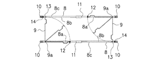
支柱7は、以下に詳述するように、天板3の四隅の手掛かり棒5を利用して、天板3の周縁部の上方において、天板3の長手方向に延伸する一対の長手側桟部材8、8と、天板3の短手方向に延伸する一対の短手側桟部材9、9とを支承するのに用いられる。
A
As will be described in detail below, the
支柱7の上部、換言すれば手掛かり棒5の上方には、一対の長手側桟部材8、8が取り付けられる。
長手側桟部材8は、例えば樹脂製の断面矩形の管体からなり、その両端が支柱7の上部に取付金具10を介して回動可能に支持されるとともに、中央部で分割されている。これにより、長手側桟部材8の分割体8a、8bを、支柱7及び手掛かり棒5に沿うように折り畳み収納することができる。
そして、天板3の四隅で手掛かり棒5及びそれに伴って支柱7を立てた状態で、長手側桟部材8の分割体8a、8bを水平位置に回動させることにより、端面同士が衝合して、長手側桟部材8を架け渡した状態とすることができる。長手側桟部材8の分割体8a、8bは、例えばスライド構造の連結部材11で脱着可能に連結される。
A pair of
The
Then, in a state where the
長手側桟部材8には、それぞれ短手側桟部材9が取り付けられる。なお、一対の短手側桟部材9は、その形状や周辺構造(長手側桟部材8への取り付け構造や係止構造)について、天板3の中心に対して点対称の関係を有する。
長手側桟部材8(分割体8a)の架け渡した状態での上面(以下、単に上面と呼ぶ)8cには、支柱7に近い位置で、短手側桟部材9の基端部9aが回動可能に支持される。短手側桟部材9は、例えばアルミニウム合金又はステンレス鋼等の金属棒で形成され、図2に示すように、基端部9aを下向きに90度に折り曲げ、長手側桟部材8への回動支持部として利用する。
このように長手側桟部材8の上面8cで短手側桟部材9の基端部9aが回動可能に支持されるので、短手側桟部材9を、長手側桟部材8に沿うように収納することができる。また、長手側桟部材8を架け渡した状態とした場合、該長手側桟部材8で支持される短手側桟部材9は垂直軸まわりに回動可能であり、対向位置の長手側桟部材8に向けて水平方向に回動させることができる。
A short
A
Thus, since the
また、図2に示すように、短手側桟部材9の先端部も下向きに90度に折り曲げ、長手側桟部材8への係止突起9bとして利用する。
図3に示すように、長手側桟部材8(分割体8a)の上面8cには係止孔12が形成されており、自身で支持する短手側桟部材9の係止突起9bを挿入することができる。これにより、短手側桟部材9を収納した状態で保持することができる。
また、図4に示すように、長手側桟部材8(分割体8b)の上面8cには係止孔13が形成されており、対向位置の長手側桟部材8で支持される短手側桟部材9の係止突起9bを挿入することができる。すなわち、短手側桟部材9を対向位置の長手側桟部材8に向けて水平方向に90度程度回動させることにより、短手側桟部材9の係止突起9bを係止孔13に挿入することができる。これにより、短手側桟部材9を架け渡した状態で保持することができる。
Further, as shown in FIG. 2, the front end portion of the short
As shown in FIG. 3, a
Further, as shown in FIG. 4, a locking
なお、図2に示すように、短手側桟部材9の適所をコ字形に突出させて取手部9cを形成するようにしてもよい。取手部9cの突出幅は、突出により形成される空間に指先が差し入れやすいものであると同時に、作業台全体を折り畳んだときに邪魔になることのない程度のものに設定する。
In addition, as shown in FIG. 2, you may make it form the
ここまで説明した構成においては、天板3の四隅で手掛かり棒5及びそれに伴って支柱7を立てた状態で、一対の長手側桟部材8、8を架け渡すことを前提として、一対の短手側桟部材9、9を架け渡すことができる。
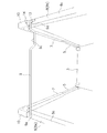
本実施形態に係る可搬式作業台では、図5に示すように、一対の長手側桟部材8、8のうちの片方だけを架け渡した状態でも、一対の短手側桟部材9、9を架け渡すことができるようになっている。
以下、一対の長手側桟部材8、8のうち、架け渡した状態の長手側桟部材を一方の長手側桟部材8Aと記し、支柱7及び手掛かり棒5に沿うように収納した状態の長手側桟部材を他方の長手側桟部材8Bと記して、詳細を説明する。
In the configuration described so far, it is assumed that the pair of short-
In the portable worktable according to the present embodiment, as shown in FIG. 5, even when only one of the pair of long
Hereinafter, of the pair of long-
一方の長手側桟部材8Aで支持される短手側桟部材9は、既述したとおり、対向位置の他方の長手側桟部材8Bに向けて水平方向に回動させることができる。
しかしながら、他方の長手側桟部材8Bは、支柱7及び手掛かり棒5に沿うように収納されているため、係止孔13の位置が、短手側桟部材9の係止突起9bを挿入することができない位置となっている。
As described above, the short
However, since the other long
そこで、本実施形態では、取付金具10(分割体8bを支持する取付金具)の頂面に、短手側桟部材9の係止突起9bを挿入する係止孔14を形成している。係止孔14は、長手側桟部材8を架け渡した状態、及び長手側桟部材8を支柱7及び手掛かり棒5に沿うように収納した状態のいずれにおいても位置が不変であり、本発明でいう短手側桟部材を係止するための係止部に相当する。これにより、短手側桟部材9を対向位置の他方の長手側桟部材8Bに向けて水平方向に90度+α程度回動させることにより、その先端部の係止突起9bを係止孔14に挿入することができる。なお、αは、係止孔13と係止孔14との位置ずれ(図4を参照のこと)に相当する角度を意味する。
Therefore, in the present embodiment, a locking
この場合に、図6に示すように、取付金具10と長手側桟部材8との取付構造によっては、取付金具10の頂面の係止孔14の下部が長手側桟部材8により閉ざされてしまう。そこで、長手側桟部材8を支柱7及び手掛かり棒5に沿うように収納した状態では、係止孔14が閉ざされないように長手側桟部材8の端部に逃げ8dを形成する等しておく。
なお、係止孔13と係止孔14とは、理論上は係止突起9bの移動軌跡上、すなわち短手側桟部材9の基端部9aを中心とする同円上に配置する必要があるが、各部の遊びにより係止突起9bを挿入できるのであれば、必ずしも同円上になくてもよい。
In this case, as shown in FIG. 6, depending on the mounting structure of the mounting
In theory, the locking
一方、他方の長手側桟部材8Bで支持される短手側桟部材9は、水平軸まわりに回動可能であり、対向位置の一方の長手側桟部材8Aに向けて垂直方向に回動させることができる。
この場合、短手側桟部材9の係止突起9bは、対向位置の一方の長手側桟部材8Aの上面8cに形成された係止孔13に対して90度位相がずれた位置関係となる。
そこで、本実施形態では、図2に示すように、短手側桟部材9の先端部に、係止突起9bとは90度位相をずらしたかたちで第2の係止突起9dを設けている。これにより、短手側桟部材9を対向位置の一方の長手側桟部材8Bに向けて垂直方向に回動させることにより、その先端部の第2の係止突起9dを係止孔13に挿入することができる。なお、本実施形態では、係止突起9bが本発明でいう第1の係止部に相当し、第2の係止突起9dが本発明でいう第2の係止部に相当する。
On the other hand, the short-
In this case, the locking
Therefore, in the present embodiment, as shown in FIG. 2, the
以上述べたように、本実施形態に係る可搬式作業台1は、一対の長手側桟部材8、8及び一対の短手側桟部材9、9で四方を囲んだ使用状態と、一対の長手側桟部材8、8のうちの片方及び一対の短手側桟部材9、9で三方を囲んだ使用状態とに選択的に設置することができる。
通常の使用状態では、四方を囲んだ状態とすることにより、天板3に立つ作業者は、上半身がいずれかの桟部材8、9に近づいたときには天板3の周縁部に近い位置に立っていることを感知することができる。そして、天板3の長手側を壁面等に近接させる使用状態では、壁面側の長手側桟部材8を収納状態として、作業性を高めることができる。このときも、壁面側以外の三方では、天板3に立つ作業者は、上半身がいずれかの桟部材8、9に近づいたときには天板3の周縁部に近づいていることを感知することができる。
As described above, the portable work table 1 according to the present embodiment includes a pair of
In a normal use state, by surrounding the four sides, the worker standing on the
なお、本実施形態に係る可搬式作業台1では、二方を囲んだ使用状態とすることも可能である。例えば一対の長手側桟部材8、8を掛け渡し、一対の短手側桟部材9、9を収納した状態とすることができる。或いは、一対の長手側桟部材8、8を収納し、一対の短手側桟部材9、9を掛け渡した状態とすることができる。すなわち、一対の長手側桟部材8を収納した状態では、短手側桟部材9を対向位置の長手側桟部材8に向けて垂直方向に回動させることができ、その先端部の係止突起9bを、取付金具10の頂面の係止孔14に挿入することができる。
さらにいえば、一対の長手側桟部材8、8及び一対の短手側桟部材9、9のうちいずれか1本だけを掛け渡した使用状態とすることもできる。
In addition, in the portable worktable 1 which concerns on this embodiment, it can also be set as the use condition which enclosed two sides. For example, the pair of long-
Furthermore, it can be in a use state in which only one of the pair of long-
以上、本発明を実施形態と共に説明したが、上記実施形態は本発明を実施するにあたっての具体化の例を示したものに過ぎず、これらによって本発明の技術的範囲が限定的に解釈されてはならないものである。すなわち、本発明はその技術思想、又はその主要な特徴から逸脱することなく、様々な形で実施することができる。
長手側桟部材8及び短手側桟部材9を含む各部の形状や構造は一例に過ぎず、これに限定されるものではない。例えば手掛かり棒5に支柱7を別途設ける構成を説明したが、手掛かり棒5で直接的に一対の長手側桟部材8、8及び一対の短手側桟部材9、9を支承するような形態としてもよい。
Although the present invention has been described together with the embodiments, the above-described embodiments are merely examples of implementation in carrying out the present invention, and the technical scope of the present invention is interpreted in a limited manner by these. It must not be. That is, the present invention can be implemented in various forms without departing from the technical idea or the main features thereof.
The shape and structure of each part including the long
また、上記実施形態では、係止孔13と係止孔14とを別個に配設する構成としたが、それに限定されるものではなく、両者を共用とする形態としてもよい。例えば図6に一点鎖線で示すように、長手側桟部材8の上面8cであって、取付金具10の頂面の係止孔14の真下に対応する位置に穴15を形成しておく。この場合、図6に示すように長手側桟部材8を架け渡した状態であっても、対向位置の長手側桟部材8で支持される短手側桟部材9の係止突起9bや第2の係止突起9dを係止孔14から穴15に挿入することができ、上記実施形態でいう係止孔13は不要となる。
Moreover, in the said embodiment, although it was set as the structure which arrange | positions the locking
1:可搬式作業台、2:主脚、3:天板、5:手掛かり棒、7:支柱、8:長手側桟部材、9:短手側桟部材、9b:係止突起、9d:第2の係止突起、13、14:係止孔 1: portable work table, 2: main leg, 3: top plate, 5: clue bar, 7: support, 8: long side beam member, 9: short side beam member, 9b: locking projection, 9d: first 2 locking projections, 13 and 14: locking holes
Claims (3)
前記天板の四隅の手掛かり棒を利用して、前記天板の上方において、前記天板の長手方向に延伸する一対の長手側桟部材と、前記天板の短手方向に延伸する一対の短手側桟部材とを支承し、
前記一対の長手側桟部材及び前記一対の短手側桟部材で四方を囲んだ使用状態と、前記一対の長手側桟部材のうちの片方及び前記一対の短手側桟部材で三方を囲んだ使用状態とに選択的に設置できるように構成され、
前記長手側桟部材は、前記手掛かり棒の上部又は上方で回動可能に支持されて、前記手掛かり棒に沿うように折り畳み収納可能であり、
前記長手側桟部材に前記短手側桟部材が回動可能に支持されており、前記短手側桟部材を対向位置の前記長手側桟部材に向けて回動させることができることを特徴とする可搬式作業台。 A portable work table spanning the short side of the top plate between a pair of main legs, and standing clue bars at the four corners of the top plate,
Using a clue bar at the four corners of the top plate, a pair of long side rail members extending in the longitudinal direction of the top plate and a pair of short members extending in the short direction of the top plate above the top plate. Supports the hand crosspiece,
The use state in which the four sides are surrounded by the pair of long side crosspiece members and the pair of short side crosspiece members, and the three sides are surrounded by one of the pair of long side crosspiece members and the pair of short side crosspiece members. It is configured so that it can be installed selectively in use .
The longitudinal beam member is rotatably supported above or above the clue bar and can be folded and stored along the cue bar.
The short side beam member is rotatably supported by the long side beam member, and the short side beam member can be rotated toward the long side beam member at the opposite position. Portable workbench.
該短手側桟部材が支持される前記長手側桟部材を架け渡した状態で、対向位置の前記長手側桟部材に向けて回動したときに係止するのに用いられる第1の係止部と、
該短手側桟部材が支持される前記長手側桟部材を前記手掛かり棒に沿うように収納した状態で、対向位置の前記長手側桟部材に向けて回動したときに係止するのに用いられる第2の係止部とを有することを特徴とする請求項1に記載の可搬式作業台。 The short side crosspiece member is
A first lock used to lock the long side beam member supported by the short side beam member when the long side beam member is rotated toward the longitudinal side beam member at the opposite position. And
Used to lock the long-side beam member supported by the short-side beam member when it is rotated toward the long-side beam member at the opposite position in a state of being accommodated along the clue bar. The portable workbench according to claim 1 , further comprising a second locking portion.
Priority Applications (1)
| Application Number | Priority Date | Filing Date | Title |
|---|---|---|---|
| JP2015108727A JP6621249B2 (en) | 2015-05-28 | 2015-05-28 | Portable worktable |
Applications Claiming Priority (1)
| Application Number | Priority Date | Filing Date | Title |
|---|---|---|---|
| JP2015108727A JP6621249B2 (en) | 2015-05-28 | 2015-05-28 | Portable worktable |
Publications (2)
| Publication Number | Publication Date |
|---|---|
| JP2016223106A JP2016223106A (en) | 2016-12-28 |
| JP6621249B2 true JP6621249B2 (en) | 2019-12-18 |
Family
ID=57747468
Family Applications (1)
| Application Number | Title | Priority Date | Filing Date |
|---|---|---|---|
| JP2015108727A Active JP6621249B2 (en) | 2015-05-28 | 2015-05-28 | Portable worktable |
Country Status (1)
| Country | Link |
|---|---|
| JP (1) | JP6621249B2 (en) |
Families Citing this family (1)
| Publication number | Priority date | Publication date | Assignee | Title |
|---|---|---|---|---|
| JP7212343B2 (en) * | 2018-05-21 | 2023-01-25 | ジー・オー・ピー株式会社 | Workbench |
Family Cites Families (5)
| Publication number | Priority date | Publication date | Assignee | Title |
|---|---|---|---|---|
| JP4043972B2 (en) * | 2003-02-27 | 2008-02-06 | 株式会社住軽日軽エンジニアリング | Folding work table and auxiliary handrail used therefor |
| JP5364241B2 (en) * | 2007-04-02 | 2013-12-11 | ジーオーピー株式会社 | Handrail for portable worktable |
| JP5694750B2 (en) * | 2010-12-09 | 2015-04-01 | 株式会社ナカオ | Work platform and bridge scaffolding plate for work platform |
| JP5412456B2 (en) * | 2011-03-15 | 2014-02-12 | アルインコ株式会社 | Workbench |
| KR20120109170A (en) * | 2011-03-28 | 2012-10-08 | 권택철 | Scaffolding ladder |
-
2015
- 2015-05-28 JP JP2015108727A patent/JP6621249B2/en active Active
Also Published As
| Publication number | Publication date |
|---|---|
| JP2016223106A (en) | 2016-12-28 |
Similar Documents
| Publication | Publication Date | Title |
|---|---|---|
| JP5300587B2 (en) | Portable work table moving device | |
| JP6621249B2 (en) | Portable worktable | |
| JP5694750B2 (en) | Work platform and bridge scaffolding plate for work platform | |
| JP6831989B2 (en) | Portable workbench | |
| JP3180629U (en) | Stepladder platform | |
| JP4170940B2 (en) | Portable worktable | |
| JP6254847B2 (en) | Stepladder platform | |
| JP2023036943A (en) | Workbench | |
| JP2022103248A (en) | Work bench | |
| JP5286197B2 (en) | Floor joint device | |
| JP2003247338A (en) | Work table | |
| JP5519320B2 (en) | Workbench with handrail | |
| JP3201332U (en) | Portable worktable | |
| JP4155937B2 (en) | Workbench with handrail | |
| JP7428425B2 (en) | Workbench | |
| JP5689280B2 (en) | Workbench | |
| KR200271780Y1 (en) | Fold And Unfold Mobile Working Platform | |
| JP2001130900A (en) | Handrail for high lift work bench | |
| JP2011169069A (en) | Portable workbench | |
| JP2011169069A5 (en) | ||
| JP3156117U (en) | Manhole ladder | |
| JP4690602B2 (en) | Workbench with handrail | |
| JP2009144361A (en) | Work bench | |
| JP5777695B2 (en) | Portable worktable | |
| KR100699009B1 (en) | A foldable working deck structure |
Legal Events
| Date | Code | Title | Description |
|---|---|---|---|
| A621 | Written request for application examination |
Free format text: JAPANESE INTERMEDIATE CODE: A621 Effective date: 20180416 |
|
| A977 | Report on retrieval |
Free format text: JAPANESE INTERMEDIATE CODE: A971007 Effective date: 20190215 |
|
| A131 | Notification of reasons for refusal |
Free format text: JAPANESE INTERMEDIATE CODE: A131 Effective date: 20190312 |
|
| A521 | Request for written amendment filed |
Free format text: JAPANESE INTERMEDIATE CODE: A523 Effective date: 20190507 |
|
| TRDD | Decision of grant or rejection written | ||
| A01 | Written decision to grant a patent or to grant a registration (utility model) |
Free format text: JAPANESE INTERMEDIATE CODE: A01 Effective date: 20191112 |
|
| A61 | First payment of annual fees (during grant procedure) |
Free format text: JAPANESE INTERMEDIATE CODE: A61 Effective date: 20191119 |
|
| R150 | Certificate of patent or registration of utility model |
Ref document number: 6621249 Country of ref document: JP Free format text: JAPANESE INTERMEDIATE CODE: R150 |
|
| R250 | Receipt of annual fees |
Free format text: JAPANESE INTERMEDIATE CODE: R250 |
|
| R250 | Receipt of annual fees |
Free format text: JAPANESE INTERMEDIATE CODE: R250 |