JP2011169069A - Portable workbench - Google Patents

Portable workbench Download PDF

Info

Publication number
JP2011169069A
JP2011169069A JP2010035744A JP2010035744A JP2011169069A JP 2011169069 A JP2011169069 A JP 2011169069A JP 2010035744 A JP2010035744 A JP 2010035744A JP 2010035744 A JP2010035744 A JP 2010035744A JP 2011169069 A JP2011169069 A JP 2011169069A
Authority
JP
Japan
Prior art keywords
bar
top plate
wife
clasp
locking
Prior art date
Legal status (The legal status is an assumption and is not a legal conclusion. Google has not performed a legal analysis and makes no representation as to the accuracy of the status listed.)
Withdrawn
Application number
JP2010035744A
Other languages
Japanese (ja)
Other versions
JP2011169069A5 (en
Inventor
Yutaka Yamaoka
豊 山岡
Kenichi Inamuro
賢一 稲室
Current Assignee (The listed assignees may be inaccurate. Google has not performed a legal analysis and makes no representation or warranty as to the accuracy of the list.)
Alinco Inc
Original Assignee
Alinco Inc
Priority date (The priority date is an assumption and is not a legal conclusion. Google has not performed a legal analysis and makes no representation as to the accuracy of the date listed.)
Filing date
Publication date
Application filed by Alinco Inc filed Critical Alinco Inc
Priority to JP2010035744A priority Critical patent/JP2011169069A/en
Publication of JP2011169069A publication Critical patent/JP2011169069A/en
Publication of JP2011169069A5 publication Critical patent/JP2011169069A5/ja
Withdrawn legal-status Critical Current

Links

Images

Landscapes

  • Ladders (AREA)

Abstract

<P>PROBLEM TO BE SOLVED: To provide a portable workbench which allows a gable side end sensing bar to be quickly and easily attached and detached. <P>SOLUTION: The portable work bench includes ladder-like leg bodies 2, 2 provided at both ends of a top plate 1, and hand-hold bars 5 erected at four corners of the top plate 1. In extending the gable side end sensing bar 7 for notifying a worker of the gable side end of the top plate 1, between the upper ends of both hand-hold bars 5, 5 facing in the short-side direction of the top plate 1, a base end 8 of the gable side end sensing bar 7 is rotatably fitted to the upper end of one hand-hold bar 5 out of both hand-hold bars 5, 5 facing in the short-side direction of the top plate 1 so that the gable side end sensing bar 7 turns along a surface orthogonal to the longitudinal direction of the top plate 1, and a locking protrusion 9 formed at the tip of the gable side end sensing bar 7 is detachably engaged into a locking hole 10 provided on the upper end side face of the other hand-hold bar 5. <P>COPYRIGHT: (C)2011,JPO&INPIT

Description

本発明は、建設現場などにおいて天井の内装仕上げや天井内の配線、配管などの作業を行う時に使用される可搬式作業台に関する。   The present invention relates to a portable work table used when performing work such as interior finishing of a ceiling, wiring in a ceiling, piping, and the like at a construction site or the like.

従来作業者が天板の上に乗って上記のような作業を行う場合、作業者は、天板から足を踏み外さないよう足元の作業位置を確認しながら作業をしなくてはいけないと思いつつも、実際の作業では、天板の端部、特に妻側端部の確認が難しく、その妻側端部から足の踏み外し現象が発生し易い状況にある。   When a conventional worker rides on the top board and performs the above-mentioned work, the worker must work while checking the work position of the step so that the foot is not removed from the top board. However, in actual work, it is difficult to check the end of the top plate, particularly the end on the side of the wife, and a situation in which the stepping off of the foot tends to occur from the end of the end of the wife.

本発明の出願人は、先に、梯子状脚体を上り下りする際の不測の落下を防止するために天板の四隅部に立設されている手掛かり棒を利用し、天板の短手方向に対向する両手掛かり棒の上端部間に妻側端部感知バーを架け渡し、作業者がこの感知バーに触った時にそこが天板の妻側端部であることを作業者に感知させ、それによって天板上での作業中に天板の妻側端部からの不測の落下を未然に防ぐようにした可搬式作業台を出願している。   The applicant of the present invention first uses a clue bar that is erected at the four corners of the top plate in order to prevent an unexpected fall when the ladder-shaped leg is ascended and descended. The wife side end detection bar is bridged between the upper ends of the two clasp bars facing in the direction, and when the operator touches this detection bar, the worker senses that it is the wife side end of the top board. Thus, a portable work table has been filed so as to prevent an unexpected fall from the end of the top side of the top plate during work on the top plate.

先の出願の作業台にあっては、天板の短手方向に対向する両手掛かり棒の上端部間に、妻側感知バーの両端部を夫々取付具を介して脱着自在に取り付けるようにしているため、妻側感知バーの取付け及び取外しに手間と時間がかかるという問題があった。   In the workbench of the previous application, both ends of the wife side detection bar are detachably attached via attachments between the upper ends of the two clasp bars facing the short direction of the top plate. Therefore, there is a problem that it takes time and effort to install and remove the wife side detection bar.

本発明は、上記の事情に鑑み、妻側端部感知バーの取り付け及び取り外しを迅速容易に行えるようにした可搬式作業台を提供することを目的とする。   In view of the above circumstances, an object of the present invention is to provide a portable work table that allows a wife end detection bar to be attached and detached quickly and easily.

上記課題を解決するための手段を、後述する実施形態の参照符号を付して説明すると、請求項1は、天板1の両端に梯子状の脚体2,2を設け、天板1の四隅部に手掛かり棒5を立設した可搬式作業台において、天板1の短手方向に対向する両手掛かり棒5,5の上端部間に、天板1の妻側端部であることを知らせるための妻側端部感知バー7を架け渡すにあたり、妻側端部感知バー7の基端部8を、天板1の短手方向に対向する両手掛かり棒5,5の一方の手掛かり棒5の上端部に、この感知バー7が天板1の長手方向と直交する面に沿って回動するように軸着し、妻側端部感知バー7の先端部に形成した係止突部9を、他方の手掛かり棒5の上端部側面に設けた係止孔10に係脱自在に係入するようにしてなることを特徴とする。   Means for solving the above problems will be described with reference numerals in the embodiments described later. Claim 1 is provided with ladder-like legs 2 and 2 at both ends of the top plate 1, In the portable work table in which the clasp bar 5 is erected at the four corners, between the upper end parts of the two clasp bars 5 and 5 facing in the short direction of the top panel 1, it is the wife side end of the top panel 1 When bridging the wife end detection bar 7 for notifying, the base end 8 of the wife end detection bar 7 is one of the two clasp bars 5 and 5 facing the short direction of the top board 1. A locking projection formed on the tip of the wife side end sensing bar 7, which is pivotally attached to the upper end of 5 so that the sensing bar 7 rotates along a plane perpendicular to the longitudinal direction of the top plate 1. 9 is configured to be detachably engaged with a locking hole 10 provided on the side surface of the upper end portion of the other clue bar 5.

請求項2は、請求項1に記載の可搬式作業台において、前記一方の手掛かり棒5の下端部側面には、妻側端部感知バー7をこの一方の手掛かり棒5に沿うように回動して折り畳んだ時に前記係止突部9が係脱自在に係入する係止孔11を設けてなることを特徴とする。   According to a second aspect of the present invention, in the portable workbench according to the first aspect, on the side of the lower end of the one clue bar 5, the wife end detection bar 7 is rotated along the one clasp bar 5. In addition, a locking hole 11 into which the locking projection 9 is detachably engaged when folded is provided.

請求項3は、請求項1に記載の可搬式作業台において、前記妻側端部感知バー7の係止突部9は、バー本体部7oの弾性力によって、前記他方の手掛かり棒5の上端部側面に設けた前記係止孔10に常時係入するように付勢されることを特徴とする。   According to a third aspect of the present invention, in the portable workbench according to the first aspect, the locking protrusion 9 of the wife side end portion sensing bar 7 has an upper end of the other clue bar 5 by the elastic force of the bar main body portion 7o. It is biased so as to be always engaged with the locking hole 10 provided on the side surface of the part.

請求項4は、請求項1に記載の可搬式作業台において、前記妻側端部感知バー7の係止突部9は、バー本体部7oの弾性力によって、前記一方の手掛かり棒5の下端部側面に設けた前記係止孔11に常時係入するように付勢されることを特徴とする。   According to a fourth aspect of the present invention, in the portable workbench according to the first aspect, the locking projection 9 of the wife side end sensing bar 7 has a lower end of the one clue bar 5 by the elastic force of the bar main body 7o. It is biased so as to always engage with the locking hole 11 provided on the side surface of the part.

上記解決手段による発明の効果を、後述する実施形態の参照符号を付して説明すると、請求項1に係る発明によれば、天板1の短手方向に対向する両手掛かり棒5,5間に妻側端部感知バー7を架け渡すのに、この感知バー7の基端部8を、天板1の短手方向に対向する両手掛かり棒5,5の一方の手掛かり棒5の上端部に、感知バー7が天板1の長手方向と直交する面に沿って回動するように軸着し、感知バー7の先端部に形成した係止突部9を、他方の手掛かり棒5の上端部側面に設けた係止孔10に係脱自在に係入するようにしたもので、妻側端部感知バー7を使用する時は、この感知バー7を、基端部8を中心に回動させて、先端部の係止突部9を、他方の手掛かり棒5の上端部側面の係止孔10に係入すればよく、また感知バー7を使用しない時は、基端部8を中心に回動させて一方の手掛かり棒5に沿うように折り畳んで収納しておくことができるから、妻側端部感知バー7の取り付け及び取り外しを迅速容易に行うことができる。   The effect of the invention by the above-described solution means will be described with reference numerals of embodiments to be described later. According to the invention according to claim 1, between the two handhold bars 5 and 5 facing the short direction of the top plate 1 In order to bridge the wife end detection bar 7, the base end 8 of the detection bar 7 is connected to the upper end of one of the clasp bars 5 and 5 facing the short direction of the top plate 1. Next, the sensing bar 7 is pivotally mounted so as to rotate along a plane orthogonal to the longitudinal direction of the top plate 1, and the locking protrusion 9 formed at the tip of the sensing bar 7 is attached to the other clue bar 5. It is designed to be detachably engaged with a locking hole 10 provided on the side surface of the upper end portion. When using the wife side end portion detection bar 7, the detection bar 7 is centered on the base end portion 8. It is only necessary to rotate and engage the locking protrusion 9 at the tip end portion with the locking hole 10 on the side surface of the upper end portion of the other clue bar 5, and the sensing bar 7. When not in use, the base end 8 can be rotated around the base end 8 so that it can be folded and stored along one of the clue bars 5 so that the wife side end detection bar 7 can be quickly and easily attached and detached. Can be done.

請求項2に係る発明によれば、前記一方の手掛かり棒5の下端部側面には、妻側端部感知バー7をこの一方の手掛かり棒5に沿うように折り畳んで収納する時に前記係止突部9が係脱自在に係入する係止孔11を設けているから、この係止孔11に係止突部9を係入することによって、妻側端部感知バー7を折り畳み収納位置に固定させことができ、可搬式作業台Tの梱包時や運搬時に感知バー7がブラブラするようなことがなく非常に有効となる。   According to the second aspect of the present invention, when the wife side end sensing bar 7 is folded along the one clasp bar 5 and stored on the side surface of the lower end of the one clue bar 5, the locking protrusion is provided. Since the locking hole 11 into which the part 9 is detachably engaged is provided, by engaging the locking projection 9 in the locking hole 11, the wife end detection bar 7 is folded into the storage position. It can be fixed, and the sensing bar 7 does not become dull when the portable work table T is packed or transported, which is very effective.

請求項3に係る発明によれば、妻側端部感知バー7の使用時に、係止突部9は、バー本体部7oの弾性力によって、前記他方の手掛かり棒5の上端部側面に設けた前記係止孔10に常時係入するように付勢されるから、感知バー7の使用時に係止突部9を係止孔10に係入した状態に保持するための特別なロック手段が不要となり、構造の簡素化を図ることができる。   According to the third aspect of the present invention, when the wife side end sensing bar 7 is used, the locking projection 9 is provided on the side of the upper end of the other clue bar 5 by the elastic force of the bar main body 7o. Since it is urged to always engage with the engaging hole 10, no special locking means for holding the engaging projection 9 in the engaging hole 10 is required when the sensing bar 7 is used. Thus, the structure can be simplified.

請求項4に係る発明によれば、妻側端部感知バー7を折り畳んだ時にも、係止突部9をバー本体部7oの弾性力によって、前記一方の手掛かり棒5の下端部側面に設けた前記係止孔11に常時係入するように付勢されるから、感知バー7の折り畳み収納時に係止突部9を係止孔11に係入した状態に保持するための特別なロック手段が不要となり、構造の簡素化を図ることができる。   According to the invention of claim 4, even when the wife side end sensing bar 7 is folded, the locking projection 9 is provided on the side surface of the lower end of the one clue bar 5 by the elastic force of the bar body 7 o. In addition, since it is urged to always engage with the engaging hole 11, a special locking means for holding the engaging protrusion 9 engaged with the engaging hole 11 when the sensing bar 7 is folded and stored. Can be eliminated, and the structure can be simplified.

(a) は本発明に係る可搬式作業台の実施形態を示す平面図、(b) は正面図である。(a) is a top view which shows embodiment of the portable worktable which concerns on this invention, (b) is a front view. (a) は同可搬式作業台の側面図、(b) は図1の(b) のA−A線拡大断面図である。(a) is a side view of the portable work table, and (b) is an AA line enlarged cross-sectional view of (b) of FIG. 図1の(a) の矢印Bで示す部分の拡大図である。It is an enlarged view of the part shown by the arrow B of (a) of FIG. (a) は両脚体を折り畳んだ状態の可搬式作業台の底面図、(b) は(a) のように折り畳んだ可搬式作業台を積み重ねた状態の正面図である。(a) is a bottom view of the portable workbench with both legs folded, and (b) is a front view with the folded portable workbench folded as shown in (a).

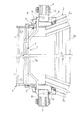
以下に本発明の可搬式作業台の好適な実施形態を図面に基づいて説明すると、図1及び図2に示す作業台Tにおいて、天板1の左右両端に、夫々梯子状の脚体2,2が、夫々回転金具3によって、図1の(a) に示すように末広がり状に傾斜して起立した開脚状態と、天板1の下面に沿うように折り畳んだ閉脚状態(図4参照)との間で開閉可能に設けられ、天板1と各脚体2との間には途中で屈曲自在なステイ4が介装されている。各梯子状脚体2は、図2の(a) に示すように若干末広がり状に配置された両側一対の脚柱2a,2aと、両脚柱2a,2a間に複数段に横架された踏桟2bとによって構成される。   A preferred embodiment of a portable worktable according to the present invention will be described below with reference to the drawings. In the worktable T shown in FIGS. 1 and 2, ladder-like legs 2, respectively, at the left and right ends of the top plate 1. 2 is a legged state in which the rotating bracket 3 stands upright as shown in FIG. 1A, and a closed leg state that is folded along the lower surface of the top plate 1 (see FIG. 4). A stay 4 is provided between the top plate 1 and each leg 2 so as to be freely bent. As shown in FIG. 2 (a), each ladder-like leg 2 is composed of a pair of leg posts 2a, 2a arranged in a slightly divergent shape, and a step horizontally laid in a plurality of stages between the two leg posts 2a, 2a. It is comprised by the crosspiece 2b.

天板1の四隅部には、脚体2と天板1との昇降口に位置するように手掛かり棒5が設けられ、各手掛かり棒5は、その下端部が、脚体2の外側面側上端部に装着された取付金具6により回転可能に枢着されて、図1の(a) 及び図2の(a) に実線で示すような起立姿勢と、図1の(a) 及び図2の(a) に仮想線で示すように、梯子状脚体2の脚柱2aに沿って折り畳まれた折畳姿勢とに姿勢変更できるようになっている。   At the four corners of the top plate 1, a clasp bar 5 is provided so as to be positioned at the elevator port between the leg 2 and the top plate 1, and each clasp bar 5 has a lower end on the outer surface side of the leg 2. It is pivotally mounted by a mounting bracket 6 attached to the upper end portion, and stands up as shown by a solid line in FIG. 1 (a) and FIG. 2 (a), and in FIG. 1 (a) and FIG. As shown by the phantom line in (a), the posture can be changed to the folded posture folded along the pillar 2a of the ladder-like leg 2.

そして、天板1の短手方向に対向する両手掛かり棒5,5の一方の手掛かり棒5の上端部と他方の手掛かり棒5の上端部との間に、天板1の妻側端部であることを知らせるための妻側端部感知バー7が架け渡されるようになっている。この妻側端部感知バー7は、天板1上で作業している作業者がこれに触れた時に、その触れた地点が天板1の桁側端部であることを感知させるためのもので、作業者が体重をかけたり、少し強く触ったら潰れるような構造的強度の弱いものであって、対向する手掛かり棒の上端部間に手摺りとして架け渡される上横桟とは全く役割が異なるものである。もっとも、構造的強度の高い手摺り部材を用いることを除外するものではない。   And between the upper end part of one clasp bar 5 and the upper end part of the other clasp bar 5 of the two clasp bars 5, 5 facing the short side direction of the top panel 1, A wives side end detection bar 7 is provided to inform the user of the existence. This wife side edge detection bar 7 is used to detect that the touching point is the end of the girder side of the top board 1 when an operator working on the top board 1 touches it. So, it is weak in structural strength so that it collapses when the operator puts weight on it or touches it a little harder, and it has no role as the upper horizontal rail spanned as a handrail between the upper ends of the opposite clue bars Is different. However, the use of a handrail member having a high structural strength is not excluded.

妻側端部感知バー7は、金属線材によって形成されたもので、図3から分かるように、その基端部8を、天板1の短手方向に対向する両手掛かり棒5,5の一方の手掛かり棒5の上端部に、この感知バー7が天板1の長手方向と直交する面に沿って回動するように軸着し、妻側端部感知バー7の先端部に形成した係止突部9を、他方の手掛かり棒5の上端部側面に設けた係止孔10に係脱自在に係入するようになっており、この係止突部9は、バー本体部7oの有する弾性力によって、前記係止孔10に常時係入するように付勢される。   The wife end detection bar 7 is formed of a metal wire. As can be seen from FIG. 3, the base end 8 of the wife side end detection bar 7 is one of the two hand-holding bars 5 and 5 facing the short side of the top plate 1. The sensing bar 7 is pivotally attached to the upper end portion of the clue bar 5 so as to rotate along a plane orthogonal to the longitudinal direction of the top plate 1, and is formed at the distal end portion of the wife side end portion sensing bar 7. The locking projection 9 is detachably engaged with a locking hole 10 provided on the side of the upper end portion of the other clue bar 5, and this locking projection 9 has the bar main body portion 7o. By the elastic force, it is urged to always engage with the locking hole 10.

この妻側端部感知バー7が枢着されている前記一方の手掛かり棒5の下端部側面には、図2の(b) に示すように、妻側端部感知バー7を当該一方の手掛かり棒5に沿うように回動して折り畳んだ時に前記係止突部9が係脱自在に係入する係止孔11を設けている。   As shown in FIG. 2 (b), on the side surface of the lower end of the one clasp bar 5 on which the wife end detection bar 7 is pivotally attached, the wife end detection bar 7 is connected to the one clue. A locking hole 11 is provided in which the locking projection 9 is detachably engaged when rotated and folded along the bar 5.

また図1の(b) 及び図3に示すように、この妻側端部感知バー7のバー本体部7oは、ある程度の剛性を持たせるために略々台形状に折曲形成されており、このバー本体部7oの一端部から直角に折曲延設された基端部8が支軸部として、一方の手掛かり棒5の上端部に回転可能に軸着されており、この本体部7oの他端部から直角に折曲延設された係止突部9が、他方の手掛かり棒5の上端部側面に設けられた係止孔10に、バー本体部7oの有する弾性力によって常時係入し得るようになっている。   Further, as shown in FIG. 1B and FIG. 3, the bar body portion 7o of the wife side end sensing bar 7 is formed in a substantially trapezoidal shape so as to have a certain degree of rigidity. A base end portion 8 bent at a right angle from one end portion of the bar main body portion 7o is pivotally attached to the upper end portion of one of the clue bars 5 as a support shaft portion. The locking protrusion 9 bent at a right angle from the other end is always engaged with the locking hole 10 provided on the side of the upper end of the other clasp bar 5 by the elastic force of the bar body 7o. You can get it.

上記のように構成される可搬式作業台Tの使用法について説明すると、図1は作業台Tの使用状態を示したもので、両脚体2,2が開脚され、各手掛かり棒5が起立姿勢に保持されていて、短手方向に対向する手掛かり棒5,5の上端部間には妻側端部感知バー7が使用状態に架け渡されている。   The usage of the portable worktable T configured as described above will be described. FIG. 1 shows the use state of the worktable T. Both legs 2 and 2 are opened, and each clasp bar 5 stands up. The wife end detection bar 7 is stretched between the upper ends of the clasp bars 5 and 5 facing in the short direction and held in the posture.

従って、脚体2から天板1に上がる作業者は、手掛かり棒5を掴むことによって安全を確保しつつ天板1の上に上がることができる。そして、天板1の上で作業する作業者は、短手方向に対向する手掛かり棒5,5間に妻側端部感知バー7が架け渡されているから、この妻側端部感知バー7に触れた時に、その触れた地点が天板1の妻側端部であることを感知することができ、その妻側端部から転落するなどの事故を防止することができる。   Therefore, an operator who goes up from the leg 2 to the top board 1 can go up on the top board 1 while securing safety by grasping the clue bar 5. An operator working on the top board 1 has the wife side end detection bar 7 spanned between the clasp bars 5 and 5 facing in the short direction. When touched, it can be sensed that the touched point is the end of the top side of the top plate 1, and accidents such as falling from the end of the end of the end of the wife can be prevented.

そして上記作業台Tを使用後に折り畳む時は、先ず、妻側端部感知バー7を折り畳む。この感知バー7の折り畳みにあたって、作業者は、図3に示すように、感知バー7の先端部側を手で矢印方向に引っ張って、弾性付勢力で手掛かり棒5の上端部側面の係止孔10に係入されている係止突部9を係止孔10から抜き出し、その状態でこの感知バー7を、図2の(a) に示すように、基端部8を中心として天板1の長手方向と直交する面に沿って約270°回動させ、先端部の係止突部9を手掛かり棒5の下端部側面にある係止孔11に係入し、図2の(a) ,(b) に仮想線で示すように手掛かり棒5の側面に添わせた収納状態に保持する。   When the work table T is folded after use, the wife end detection bar 7 is first folded. When the sensing bar 7 is folded, as shown in FIG. 3, the operator pulls the tip end side of the sensing bar 7 in the direction of the arrow by hand, and the engaging hole on the side surface of the upper end of the clasp bar 5 with elastic biasing force. The locking projection 9 engaged with the cable 10 is extracted from the locking hole 10, and in this state, the sensing bar 7 is moved around the base end 8 as shown in FIG. 2 is rotated about 270 ° along a plane orthogonal to the longitudinal direction of the rod, and the locking projection 9 at the tip is engaged with the locking hole 11 on the side of the lower end of the clasp bar 5, and FIG. , (B) is held in the storage state along the side surface of the clue bar 5 as indicated by phantom lines.

こうして妻側端部感知バー7を手掛かり棒5に沿うように折り畳み収納した後、各手掛かり棒5を、図1の(a) 及び図2の(a) に仮想線で示すように脚体2の脚柱2aに沿って折り畳み、そしてさらに図4の(a) ,(b) に示すように、両脚体2,2を天板1の下面に平行に沿うように折り畳み閉脚して、作業台Tの全体が偏平状態となるように折り畳む。このように作業台Tの全体を偏平状態に折り畳むことにより、運搬や保管に便利となる。図4の(b) は偏平状態に折り畳んだ複数の作業台Tを積み重ねた状態を示す。   After the wife side end detection bar 7 is folded and stored along the clue bar 5 in this way, each clasp bar 5 is attached to the leg 2 as shown in phantom lines in FIGS. 1 (a) and 2 (a). 4a, and then, as shown in FIGS. 4 (a) and 4 (b), both legs 2 and 2 are folded so as to be parallel to the lower surface of the top board 1 and closed. Fold so that the entire T is flat. Thus, by folding the entire work table T in a flat state, it becomes convenient for transportation and storage. FIG. 4B shows a state in which a plurality of work tables T folded in a flat state are stacked.

尚、妻側端部感知バー7を折り畳み収納した手掛かり棒5を図1の(a) 及び図2の(a) に仮想線で示すように脚体2の脚柱2aに沿って折り畳んだ状態から、妻側端部感知バー7を同図の実線で示す使用状態とするには、上述した折り畳み時の操作と逆の操作を行えばよい。即ち、各手掛かり棒5を折り畳み姿勢から起立姿勢に立ち上げた後、弾性付勢力で手掛かり棒5の下端部側面の係止孔11に係入されている感知バー7の係止突部9を、その係止孔11から抜き出して、この感知バー7を、基端部8を中心に天板1の長手方向と直交する面に沿って図2の(a) に示す矢印と反対方向に約270°回動させ、先端部の係止突部9を他方の手掛かり棒5の上端部側面にある係止孔10に係入させればよい。   Note that the clasp bar 5 in which the wife side end detection bar 7 is folded and stored is folded along the pedestal 2a of the leg 2 as shown in phantom lines in FIGS. 1 (a) and 2 (a). Therefore, in order to set the wife end detection bar 7 to the use state indicated by the solid line in FIG. That is, after each clasp bar 5 is raised from the folded position to the standing position, the locking projection 9 of the sensing bar 7 that is engaged in the locking hole 11 on the side surface of the lower end of the clasp bar 5 is elastically biased. Then, the sensor bar 7 is extracted from the locking hole 11 so that the sensing bar 7 extends about the base end 8 in the direction opposite to the arrow shown in FIG. It is only necessary to rotate 270 ° and engage the locking projection 9 at the tip with the locking hole 10 on the side of the upper end of the other clue bar 5.

以上説明した可搬式作業台Tによれば、天板1の短手方向に対向する両手掛かり棒5,5間に妻側端部感知バー7を架け渡すにあたり、この感知バー7の基端部8を、天板1の短手方向に対向する両手掛かり棒5,5の一方の手掛かり棒5の上端部に、感知バー7が天板1の長手方向と直交する面に沿って回動するように軸着し、感知バー7の先端部に形成した係止突部9を、他方の手掛かり棒5の上端部側面に設けた係止孔10に係脱自在に係入するようにしたもので、妻側端部感知バー7の使用あたっては、この感知バー7を、一方の手掛かり棒5の上端部に軸着されている基端部8を中心に回動させて、先端部の係止突部9を、他方の手掛かり棒5の上端部側面の係止孔10に係入すればよく、また感知バー7を使用しない時は、他方の手掛かり棒5の上端部側面の係止孔10に係入されている係止突部9を抜き出して、基端部8を中心に図2の(a) に矢印で示すように約270°回動させて一方の手掛かり棒5に沿うように折り畳み収納すればよいから、妻側端部感知バー7の取り付け及び取り外しを迅速容易に行うことができる。   According to the portable worktable T described above, the base end portion of the sensing bar 7 is provided when the wife side end sensing bar 7 is bridged between the two hand-holding bars 5 and 5 facing in the short direction of the top board 1. The sensing bar 7 is rotated along a surface perpendicular to the longitudinal direction of the top plate 1 at the upper end of one of the two holding rods 5 and 5 facing the short side direction of the top plate 1. The locking protrusion 9 formed on the tip of the sensing bar 7 is removably engaged with the locking hole 10 provided on the side of the upper end of the other clasp bar 5. In using the wife side end detection bar 7, the detection bar 7 is rotated around the base end 8 pivotally attached to the upper end of one of the clue bars 5, The locking protrusion 9 may be engaged with the locking hole 10 on the side of the upper end of the other clue bar 5, and when the sensing bar 7 is not used, the other The locking protrusion 9 inserted in the locking hole 10 on the side surface of the upper end of the clasp bar 5 is extracted, and about 270 ° as shown by the arrow in FIG. Since it suffices to fold and store the cue bar 5 along one of the clue bars 5, it is possible to quickly and easily attach and detach the wife end detection bar 7.

また、一方の手掛かり棒5の下端部側面には、妻側端部感知バー7をこの一方の手掛かり棒5に沿うように回動して折り畳んだ時に係止突部9が係脱自在に係入する係止孔11を設けているから、感知バー7を折り畳み収納位置に固定させことができ、可搬式作業台Tの梱包時や運搬時に感知バー7がブラブラするようなことがなく非常に有効である。   Further, on the side surface of the lower end of one of the clue bars 5, the locking protrusion 9 is detachably engaged when the wife side end detection bar 7 is rotated and folded along the one clasp bar 5. Since the locking hole 11 is provided, the sensing bar 7 can be fixed in the folded storage position, and the sensing bar 7 does not rub when the portable work table T is packed or transported. It is valid.

また、この妻側端部感知バー7は、使用時には、係止突部9が、バー本体部7oの弾性付勢力によって、他方の手掛かり棒5の上端部側面に設けた係止孔10に常時係入するように付勢されるし、またこの感知バー7の折り畳んだ時にも、係止突部9が、同じくバー本体部7oの弾性付勢力によって、一方の手掛かり棒5の下端部側面に設けた係止孔11に常時係入するように付勢されるから、使用時及び折り畳み収納時に係止突部9を係止孔10に係入した状態に保持するための特別なロック手段が不要となって、構造の簡素化を図ることができる。   Further, when this wife side end sensing bar 7 is used, the locking projection 9 is always in the locking hole 10 provided on the side surface of the upper end of the other clasp bar 5 by the elastic biasing force of the bar body 7o. When the sensing bar 7 is folded, the latching projection 9 is also applied to the side surface of the lower end of the one clasp bar 5 by the elastic biasing force of the bar body 7o. Since it is urged to always engage with the provided locking hole 11, there is a special locking means for holding the locking projection 9 engaged with the locking hole 10 during use and folding storage. It becomes unnecessary, and the structure can be simplified.

T 可搬式作業台
1 天板
2 脚体
2a 脚柱
2b 踏桟
5 手掛かり棒
7 妻側端部感知バー
7o バー本体部
8 妻側端部感知バーの基端部
9 妻側端部感知バーの先端部の係止突部
10 係止孔
11 係止孔
T portable work table 1 top plate 2 leg 2a pedestal 2b pedestrian cross 5 handle bar 7 wife side end sensing bar 7o bar body 8 base end of wife side end sensing bar 9 wife side end sensing bar Locking protrusion 10 at the tip 10 Locking hole 11 Locking hole

Claims (4)

天板の両端に梯子状の脚体を設け、天板の四隅部に手掛かり棒を立設した可搬式作業台において、天板の短手方向に対向する両手掛かり棒の上端部間に、天板の妻側端部であることを知らせるための妻側端部感知バーを架け渡すにあたり、妻側端部感知バーの基端部を、天板の短手方向に対向する両手掛かり棒の一方の手掛かり棒の上端部に、この感知バーが天板の長手方向と直交する面に沿って回動するように軸着し、妻側端部感知バーの先端部に形成した係止突部を他方の手掛かり棒の上端部側面に設けた係止孔に係脱自在に係入するようにしてなる可搬式作業台。   In a portable work bench that has ladder-shaped legs at both ends of the top plate and has clue bars erected at the four corners of the top plate, the top plate is placed between the top ends of the two clasp bars facing the short direction of the top plate. When bridging the wife side edge detection bar to inform that it is the wife side edge of the board, the base end of the wife side edge detection bar is placed on one of the two-handed clasp bars facing the short side of the top board. The sensing bar is pivotally attached to the upper end of the cue bar so that the sensing bar rotates along a plane perpendicular to the longitudinal direction of the top plate, and a locking projection formed on the tip of the wife side end sensing bar is provided. A portable work table that is detachably engaged with a locking hole provided on the side surface of the upper end of the other clue bar. 前記一方の手掛かり棒の下端部側面には、妻側端部感知バーをこの一方の手掛かり棒に沿うように回動して折り畳んだ時に前記係止突部が係脱自在に係入する係止孔を設けてなる請求項1に記載の可搬式作業台。   The locking protrusion in which the locking protrusion is removably engaged when the wife side end detection bar is rotated and folded along the one holding bar on the side surface of the lower end of the one holding bar. The portable workbench according to claim 1, wherein a hole is provided. 前記妻側端部感知バーの係止突部は、バー本体部の弾性力によって、前記他方の手掛かり棒の上端部側面に設けた前記係止孔に常時係入するように付勢される請求項1に記載の可搬式作業台。   The locking protrusion of the wife side end detection bar is urged so as to be always engaged with the locking hole provided on the side of the upper end of the other clasp bar by the elastic force of the bar main body. Item 2. The portable workbench according to Item 1. 前記妻側端部感知バーの係止突部は、バー本体部の弾性力によって、前記一方の手掛かり棒の上端部側面に設けた前記係止孔に常時係入するように付勢される請求項2に記載の可搬式作業台。   The locking protrusion of the wife side end detection bar is urged so as to be always engaged with the locking hole provided on the side of the upper end of the one clasp bar by the elastic force of the bar body. Item 3. The portable work table according to Item 2.
JP2010035744A 2010-02-22 2010-02-22 Portable workbench Withdrawn JP2011169069A (en)

Priority Applications (1)

Application Number Priority Date Filing Date Title
JP2010035744A JP2011169069A (en) 2010-02-22 2010-02-22 Portable workbench

Applications Claiming Priority (1)

Application Number Priority Date Filing Date Title
JP2010035744A JP2011169069A (en) 2010-02-22 2010-02-22 Portable workbench

Publications (2)

Publication Number Publication Date
JP2011169069A true JP2011169069A (en) 2011-09-01
JP2011169069A5 JP2011169069A5 (en) 2011-12-08

Family

ID=44683457

Family Applications (1)

Application Number Title Priority Date Filing Date
JP2010035744A Withdrawn JP2011169069A (en) 2010-02-22 2010-02-22 Portable workbench

Country Status (1)

Country Link
JP (1) JP2011169069A (en)

Cited By (2)

* Cited by examiner, † Cited by third party
Publication number Priority date Publication date Assignee Title
JP2012092617A (en) * 2010-10-28 2012-05-17 Alinco Inc Work bench
JP2013209803A (en) * 2012-03-30 2013-10-10 Sanki Eng Co Ltd Portable workbench

Cited By (2)

* Cited by examiner, † Cited by third party
Publication number Priority date Publication date Assignee Title
JP2012092617A (en) * 2010-10-28 2012-05-17 Alinco Inc Work bench
JP2013209803A (en) * 2012-03-30 2013-10-10 Sanki Eng Co Ltd Portable workbench

Similar Documents

Publication Publication Date Title
KR20080023227A (en) Folding work bench
JP5364241B2 (en) Handrail for portable worktable
JP4843381B2 (en) Portable worktable and handrail member
JP2011169069A (en) Portable workbench
JP5694750B2 (en) Work platform and bridge scaffolding plate for work platform
JP2011169069A5 (en)
JP4658698B2 (en) Portable worktable
JP5406009B2 (en) Portable worktable
US20160016304A1 (en) Foldable workbench
JP2011163068A (en) Transportable workbench
JP2017145630A (en) Scaffold base with carriage function
JP2989166B2 (en) Aluminum-made portable working base
KR200452970Y1 (en) safety bar assembly and work table with safety bar
GB2467963A (en) Workhorse capable of working at different levels
JP2011163068A5 (en)
JP5627289B2 (en) Overhang scaffold for portable worktable
KR20110008510U (en) Stopper of a workbench
JP3113438U (en) Tool stand for stepladder
JP2009144361A (en) Work bench
JP2012148065A (en) Portable placing table and wheeled luggage
JP2020002651A (en) Workbench unit
JP5689280B2 (en) Workbench
JP2011140776A (en) Work position sensing device of working platform
KR20130004550U (en) The safety worktable which the hand carried is easy
JP2011094378A (en) Working position sensor in workbench

Legal Events

Date Code Title Description
A521 Written amendment

Free format text: JAPANESE INTERMEDIATE CODE: A523

Effective date: 20111020

A300 Withdrawal of application because of no request for examination

Free format text: JAPANESE INTERMEDIATE CODE: A300

Effective date: 20130507