JP6615492B2 - Motor coil stripping apparatus and method {Apparatus and Methodforpeelingcoilofmotor} - Google Patents
Motor coil stripping apparatus and method {Apparatus and Methodforpeelingcoilofmotor} Download PDFInfo
- Publication number
- JP6615492B2 JP6615492B2 JP2015104683A JP2015104683A JP6615492B2 JP 6615492 B2 JP6615492 B2 JP 6615492B2 JP 2015104683 A JP2015104683 A JP 2015104683A JP 2015104683 A JP2015104683 A JP 2015104683A JP 6615492 B2 JP6615492 B2 JP 6615492B2
- Authority
- JP
- Japan
- Prior art keywords
- coil
- tip
- peeling
- unit
- motor
- Prior art date
- Legal status (The legal status is an assumption and is not a legal conclusion. Google has not performed a legal analysis and makes no representation as to the accuracy of the status listed.)
- Active
Links
- 238000000034 method Methods 0.000 title claims description 18
- 239000011247 coating layer Substances 0.000 claims description 21
- 230000001678 irradiating effect Effects 0.000 claims description 6
- 230000004044 response Effects 0.000 claims description 4
- 238000004519 manufacturing process Methods 0.000 description 3
- 230000009471 action Effects 0.000 description 2
- 230000008859 change Effects 0.000 description 2
- 230000000694 effects Effects 0.000 description 2
- 230000008569 process Effects 0.000 description 2
- RYGMFSIKBFXOCR-UHFFFAOYSA-N Copper Chemical group [Cu] RYGMFSIKBFXOCR-UHFFFAOYSA-N 0.000 description 1
- 229910052802 copper Inorganic materials 0.000 description 1
- 239000010949 copper Substances 0.000 description 1
- 238000010586 diagram Methods 0.000 description 1
- 230000020169 heat generation Effects 0.000 description 1
- 230000003993 interaction Effects 0.000 description 1
- 238000012986 modification Methods 0.000 description 1
- 230000004048 modification Effects 0.000 description 1
- 230000002093 peripheral effect Effects 0.000 description 1
- 238000000926 separation method Methods 0.000 description 1
Images


Classifications
-
- H—ELECTRICITY
- H02—GENERATION; CONVERSION OR DISTRIBUTION OF ELECTRIC POWER
- H02G—INSTALLATION OF ELECTRIC CABLES OR LINES, OR OF COMBINED OPTICAL AND ELECTRIC CABLES OR LINES
- H02G1/00—Methods or apparatus specially adapted for installing, maintaining, repairing or dismantling electric cables or lines
- H02G1/12—Methods or apparatus specially adapted for installing, maintaining, repairing or dismantling electric cables or lines for removing insulation or armouring from cables, e.g. from the end thereof
- H02G1/1275—Methods or apparatus specially adapted for installing, maintaining, repairing or dismantling electric cables or lines for removing insulation or armouring from cables, e.g. from the end thereof by applying heat
- H02G1/128—Methods or apparatus specially adapted for installing, maintaining, repairing or dismantling electric cables or lines for removing insulation or armouring from cables, e.g. from the end thereof by applying heat using radiant energy, e.g. a laser beam
-
- H—ELECTRICITY
- H01—ELECTRIC ELEMENTS
- H01R—ELECTRICALLY-CONDUCTIVE CONNECTIONS; STRUCTURAL ASSOCIATIONS OF A PLURALITY OF MUTUALLY-INSULATED ELECTRICAL CONNECTING ELEMENTS; COUPLING DEVICES; CURRENT COLLECTORS
- H01R43/00—Apparatus or processes specially adapted for manufacturing, assembling, maintaining, or repairing of line connectors or current collectors or for joining electric conductors
- H01R43/28—Apparatus or processes specially adapted for manufacturing, assembling, maintaining, or repairing of line connectors or current collectors or for joining electric conductors for wire processing before connecting to contact members, not provided for in groups H01R43/02 - H01R43/26
-
- H—ELECTRICITY
- H02—GENERATION; CONVERSION OR DISTRIBUTION OF ELECTRIC POWER
- H02K—DYNAMO-ELECTRIC MACHINES
- H02K15/00—Methods or apparatus specially adapted for manufacturing, assembling, maintaining or repairing of dynamo-electric machines
- H02K15/0056—Manufacturing winding connections
-
- H—ELECTRICITY
- H02—GENERATION; CONVERSION OR DISTRIBUTION OF ELECTRIC POWER
- H02K—DYNAMO-ELECTRIC MACHINES
- H02K15/00—Methods or apparatus specially adapted for manufacturing, assembling, maintaining or repairing of dynamo-electric machines
- H02K15/0056—Manufacturing winding connections
- H02K15/0068—Connecting winding sections; Forming leads; Connecting leads to terminals
Landscapes
- Engineering & Computer Science (AREA)
- Manufacturing & Machinery (AREA)
- Power Engineering (AREA)
- Physics & Mathematics (AREA)
- Optics & Photonics (AREA)
- Manufacture Of Motors, Generators (AREA)
Description
本発明は、モーターのコイル剥離装置及び方法に関し、特にレーザーを用いたモーターのコイル剥離装置及び方法に関する。 The present invention relates to a motor coil peeling apparatus and method, and more particularly to a motor coil peeling apparatus and method using a laser.
モーターの場合、回転可能に形成されるシャフトと、シャフトに結合されるローターと、ハウジング内側に固定されるステーターが設けられるが、ローターの縁に沿って間隙を置いてステーターが設置される。そして、ステーターには回転磁界を形成するコイルが巻線されてローターとの電気的相互作用を誘発してローターの回転を誘導する。 In the case of a motor, a shaft formed to be rotatable, a rotor coupled to the shaft, and a stator fixed to the inside of the housing are provided, and the stator is installed with a gap along the edge of the rotor. A coil that forms a rotating magnetic field is wound around the stator to induce an electrical interaction with the rotor to induce rotation of the rotor.
ステーターの上段には、コイルと電気的に連結されるバスバーが配置される。バスバーは、一般的にリング形状のバスバー本体とバスバー本体から延長されて曲がって形成され、コイルのティップ(tip)部分が連結されるターミナルを備える。 A bus bar electrically connected to the coil is disposed on the upper stage of the stator. The bus bar generally includes a ring-shaped bus bar body and a terminal extending from the bus bar body and bent, and having a terminal to which a tip portion of the coil is connected.
このとき、コイルのティップ(tip)部分は、バスバーのターミナルにヒュージング(fusing)されて結合されるが、電流が流れて抵抗発熱が発生する場合、ヒュージング過程の中で持続的にコイルのコーティング層が燃焼し、コイルとターミナルとの間に異物を残すことになる。このように、ヒュージング過程の中でコイルとターミナルとの間に異物が残存すると、接合力が大きく低下するという問題点がある。 At this time, the tip portion of the coil is fused and coupled to the terminal of the bus bar. However, when resistance heat is generated due to current flow, the coil is continuously connected during the fusing process. The coating layer burns, leaving a foreign object between the coil and the terminal. As described above, if foreign matter remains between the coil and the terminal during the fusing process, there is a problem in that the bonding force is greatly reduced.
ここで、本発明は上記の問題点を解決するために、バスバーのターミナルと連結されるコイルの端部分を容易に剥離してコイルとバスバーの接合力を高めることができるモーターのコイル剥離装置及び方法を提供することを目的とする。 Here, in order to solve the above-described problems, the present invention can easily peel the end portion of the coil connected to the terminal of the bus bar to increase the bonding force between the coil and the bus bar. It aims to provide a method.
本発明が解決しようとする課題は、上記で言及された課題に限定されず、ここで言及されない他の課題は、以下の記載から当業者に明確に理解され得る。 The problems to be solved by the present invention are not limited to the problems mentioned above, and other problems not mentioned here can be clearly understood by those skilled in the art from the following description.
上記の目的を達成するための本発明は、コイルがマウンティングされるパレット部と、長さ方向に長く形成されて前記パレット部を移送させる移送部と、前記移送部の側面に位置し、剥離作業地点においてレーザーを照射して前記コイルのティップのコーティング層を剥離するレーザー照射部を備えるモーターのコイル剥離装置を提供することができる。 In order to achieve the above object, the present invention provides a pallet part on which a coil is mounted, a transfer part that is formed long in the length direction and transfers the pallet part, and is located on a side surface of the transfer part, and is a peeling operation. It is possible to provide a motor coil peeling apparatus including a laser irradiation unit that irradiates a laser at a spot to peel off the coating layer of the coil tip.
好ましくは、前記移送部の側面に位置し、前記移送部に向かって移動可能に形成されて前記コイルのティップを固定するクランプをさらに備えることができる。 Preferably, the apparatus may further include a clamp that is located on a side surface of the transfer unit and is formed to be movable toward the transfer unit to fix the tip of the coil.
好ましくは、前記コイルのティップが、前記剥離作業地点に位置するように、前記移送部の動きを制御する制御部をさらに備えることができる。 Preferably, the coil tip may further include a control unit that controls the movement of the transfer unit such that the tip of the coil is located at the peeling work point.
好ましくは、前記パレット部には、前記コイルのティップが直立されるようにマウンティングされ得る。 Preferably, the pallet part may be mounted so that the tip of the coil is upright.
好ましくは、前記パレット部は、回転可能に形成され得る。 Preferably, the pallet part may be formed to be rotatable.
好ましくは、前記制御部は、入力信号に対応して前記パレット部の回転を制御することができる。 Preferably, the control unit can control rotation of the pallet unit in response to an input signal.
好ましくは、前記レーザー部は、前記剥離作業地点を中心として回動可能に形成され得る。 Preferably, the laser part may be formed to be rotatable about the peeling work point.
好ましくは、前記レーザー部は、上下移動可能に形成され得る。 Preferably, the laser part may be formed to be movable up and down.
好ましくは、前記制御部は、入力信号に対応して前記レーザー部の回動または上下移動を制御することができる。 Preferably, the control unit can control rotation or vertical movement of the laser unit in response to an input signal.
上記の目的を達成するための他の発明は、a)コイルをパレット部にマウンティングする段階と、b)前記パレット部を剥離作業地点まで移送させる段階と、c)前記剥離作業地点で前記コイルのティップを固定する段階及びd)レーザーを照射して前記コイルのティップのコーティング層を剥離する段階とを含むモーターのコイル剥離方法を提供することができる。 Another invention for achieving the above object includes: a) a step of mounting a coil on a pallet part; b) a step of transferring the pallet part to a peeling work point; and c) a step of moving the coil at the peeling work point. And d) peeling the coating layer of the tip of the coil by irradiating with a laser.
好ましくは、前記d)段階において、円周方向を基準として前記コイルのティップの一部領域に該当するコーティング層を剥離することができる。 Preferably, in the step d), a coating layer corresponding to a partial region of the tip of the coil can be peeled with reference to the circumferential direction.
好ましくは、前記d)段階において、前記剥離作業地点で前記パレット部を回転させることができる。 Preferably, in the step d), the pallet portion can be rotated at the peeling work point.
好ましくは、前記d)段階において、前記剥離作業地点を中心として前記レーザー部を回転させることができる。 Preferably, in the step d), the laser unit can be rotated about the peeling work point.
好ましくは、前記d)段階において、前記剥離作業地点で前記レーザー部を上下移動させることができる。 Preferably, in the step d), the laser unit can be moved up and down at the peeling work point.
本発明の一実施例によれば、コイルのティップ部分にレーザーを照射してコーティング層を容易に剥離することによって、コイルとバスバーの接合力をより容易に増加させることができる有利な効果を提供する。 According to an embodiment of the present invention, an advantageous effect can be obtained in which the bonding force between the coil and the bus bar can be increased more easily by irradiating the tip portion of the coil with a laser to easily peel the coating layer. To do.
また、本発明の一実施例によれば、レーザーの照射位置を調節できるように構成してステーター及びバスバーの構造に対応してコイルの剥離領域の幅、長さ及び位置などを容易に変更することができる有利な効果を提供する。 Also, according to an embodiment of the present invention, the laser irradiation position can be adjusted, and the width, length, position, etc. of the coil peeling area can be easily changed corresponding to the structure of the stator and bus bar. Provide an advantageous effect that can.
以下、本発明の好ましい実施例を添付された図を参照して詳しく説明する。本発明の目的、特定の長所及び新規な特徴は、添付された図と連関される以下の詳細な説明と好ましい実施例からさらに明らかになる。そして、本明細書及び特許請求の範囲に使用された用語や単語は、通常的や辞書的な意味に限定して解釈されてはならず、発明者はその自分の発明を最善の方法で説明するために、用語の概念を適切に定義できるという原則に基づいて、本発明の技術的思想に符する意味や概念として解釈されなければならない。そして、本発明の説明において、本発明の要旨を不必要に曖昧にし得る、関連する公知技術に対する詳細な説明は省略する。 Hereinafter, preferred embodiments of the present invention will be described in detail with reference to the accompanying drawings. Objects, specific advantages and novel features of the present invention will become more apparent from the following detailed description and preferred embodiments, when taken in conjunction with the accompanying drawings. The terms and words used in this specification and the claims should not be construed to be limited to ordinary or lexicographic meanings, and the inventor best describes the invention. Therefore, based on the principle that the concept of the term can be appropriately defined, it must be interpreted as a meaning or concept corresponding to the technical idea of the present invention. In the description of the present invention, detailed descriptions of related known techniques that may unnecessarily obscure the subject matter of the present invention are omitted.
本出願において、使用した用語は、単に特定の実施例を説明するために使用されたものであって、本発明を限定しようとする意図ではない。単数の表現は文脈上明らかに異なる意味ではない限り、複数の表現を含む。本出願において、“含む" または “有する"などの用語は明細書上に記載された特徴、数字、段階、動作、構成要素、部品またはこれらを組み合わせたものが存在することを指定しようとするものであって、一つまたはそれ以上の他の特徴や数字、段階、動作、構成要素、部品またはこれらを組み合わせたものなどの存在または付加可能性を予め排除しないことと理解されなければならない。 In this application, the terminology used is merely used to describe a particular embodiment, and is not intended to limit the present invention. An expression used in the singular encompasses the expression of the plural, unless it has a clearly different meaning in the context. In this application, terms such as “comprising” or “having” are intended to indicate that there is a feature, number, step, action, component, part, or combination thereof described in the specification. However, it should be understood that the existence or additional possibilities of one or more other features or numbers, steps, actions, components, parts or combinations thereof are not excluded in advance.
図1は、ステーターコイルとバスバーとを示した図である。 FIG. 1 is a view showing a stator coil and a bus bar.
図1を参照すると、ステーター1には、回転磁界を形成するコイル10が巻線されて、コイル10のティップ部11はステーター1の上方に突き出されるように形成され得る。ステーター1の上段には環形のバスバー2が結合され得る。このとき、コイル10のティップ部11はバスバー2のターミナルにヒュージングされて結合され得る。
Referring to FIG. 1, a
上述したように、コイル10のコーティング層が剥離されず、バスバー2のターミナルにヒュージングされる場合、コイル10のコーティング層が抵抗発熱のために、燃焼して異物を残すことがある。このような残存異物はコイル10のティップ部11とバスバー2のターミナルとの接合力を大きく低下させるという問題点があった。ここで、機械的にコイル10のティップ部11を剥離しようとする方案があるが、生産工程において精密性と効率性とが低下するという問題点があった。本発明の一実施例によるモーターのコイル剥離装置及び方法は、このような問題を根本的に解決するために光学的にコイル10のコーティング層を剥離させようと提案された装置及び方法である。
As described above, when the coating layer of the
図2は、本発明の好ましい一実施例によるモーターのコイル剥離装置を示した図である。 FIG. 2 is a view showing a motor coil peeling apparatus according to a preferred embodiment of the present invention.
図2を参照すると、本発明の好ましい一実施例によるモーターのコイル剥離装置は、パレット部110と、移送部120と、クランプ130と、レーザー照射部140とを備えることができる。
Referring to FIG. 2, the motor coil peeling apparatus according to a preferred embodiment of the present invention may include a
パレット部110には、コイル10がマウンティングされ得る。このとき、コイル10のティップ部11が直立するようにパレット部110にマウンティングされ得る。分割コア方式のモーターを製造する場合、分割コアに巻かれるコイル別にパレット部110にマウンティングされ得る。円筒コア方式のモーターを製造する場合、単一コイルがパレット部110にマウンティングされ得る。
The
また、パレット部110には、バスバーにヒュージングされる前の状態で、ハウジング、ステーター、ローター及びシャフトなどが組み立てられたほぼ完製品状態のモーターがマウンティングされ得る。
The
一方、断面が円形とされるコイル10のティップ部11のコーティング層10bを剥離するために、パレット部110は剥離作業地点Aにおいて回転可能になるように形成され得る。このとき、パレット部110は、できるかぎり直立したコイル10のティップ部11の長さ方向が回転軸方向となるように形成され得る。
On the other hand, in order to peel the
このようなパレット部110は、移送部120の移送ベルト121上に積まれて運搬され得る。
Such a
移送部120は、長さ方向に長く形成された移送ベルト121を駆動モーター122で移動させることによって、移送ベルト121に積まれたパレット部110を剥離作業地点Aまで移送させて、剥離作業が終わったパレット部110を以後の組み立て作業のコンベヤーラインに移送させる役割をする。図には示さなかったが、移送ベルト121には、パレット部110が装着される別途のジグモジュールが具備され得る。
The
図3は、クランプによって固定されたコイルのティップ部を示した図である。
クランプ130は、剥離作業地点Aにおいてコイル10のティップ部11を固定する役割をすることができる。クランプ130は、コイル10のティップ部11が直立した状態でティップ部11を間に置き、ティップ部11と接触する一組の固定バー131を備えることができる。このようなクランプ130は、移送部120の両側面にそれぞれ配置され得、剥離作業地点Aに向かって移動可能となるように形成され得る。
FIG. 3 is a view showing a tip portion of a coil fixed by a clamp.
The
レーザー照射部140は、剥離作業地点Aにおいてコイル10のティップ部11にレーザーを照射してコーティング層(図5の10b)を燃焼させることによって、コイル10のティップ部11を剥離させる役割をすることができる。このようなレーザー照射部140は、剥離作業地点Aを基準として移送部120の側面に配置され得る。
The
一実施例において、レーザー照射部140は、極超短パルスレーザー(フェムト秒領域)を照射してコイル10の銅領域(図5の10a)が損傷なく精密にコーティング層10bを剥離するように形成され得る。極超短波レーザーパルスの場合、加工領域以外の周辺領域に熱伝達及び損傷がほぼないためである。
In one embodiment, the
レーザー照射部140に照射されるレーザーパルスの波長、パルス幅、パルス繰返し率及びパルスエネルギーなどはコイル10の直径、コーティング層10bの厚さ、剥離領域の長さなどを考慮して適切に変更され得る。
The wavelength, pulse width, pulse repetition rate, and pulse energy of the laser pulse irradiated to the
レーザー照射部140に隣接した位置には、スキャナ(scanner)が配置され得る。スキャナは、レーザー照射部140の位置を変更せずに、レンズまたは反射鏡を通じてレーザーパルスの方向を変更させることができる。
A scanner may be disposed at a position adjacent to the
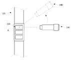
図4は、剥離作業地点を中心として回動するレーザー部を示した図である。
また、図4で示したように、レーザー照射部140は剥離作業地点Aを中心として回動可能に形成され得る。これは、断面が円形とされるコイル10のティップ部11のコーティング層10bを剥離するために、レーザーの照射領域を変更するためである。そして、レーザー照射部140は、上下方向に高さの調節が可能となるように形成され得る。これは、モーターの特性によりコイル10の剥離領域の長さを調節するためである。
FIG. 4 is a diagram showing a laser unit that rotates around the peeling work point.
In addition, as shown in FIG. 4, the
図5は、照射されたレーザーによりコーティング層が剥離されたコイルの断面を示した図であり、図6は図2のモーターのコイル剥離装置によって剥離されたコイルの剥離領域を示した写真である。 FIG. 5 is a view showing a cross section of the coil from which the coating layer has been peeled off by the irradiated laser, and FIG. 6 is a photograph showing a peeling area of the coil peeled off by the coil peeling device of the motor of FIG. .
図5を参照すると、レーザーの照射領域でコイル10のコーティング層10bが剥離されることが分かる。その結果、図6に示したように、ティップ部11に剥離領域11aが形成されることが分かる。
Referring to FIG. 5, it can be seen that the
このようなコイル10の剥離領域は、コイル10とバスバー2とのヒュージング強度を高める役割をする。コイル10のコーティング層10bをレーザーで剥離した場合、接合面の間にコーティング層10bの残存物が残らないため、接合力を大きく高めることができる。
Such a peeling region of the
一方、コイル10の剥離領域は、円周方向に沿って全体的に形成されなくても構わず、モーターの特性により円周方向を基準としてバスバー2のターミナルと接触する一部領域のみを剥離しても接合力を高めることができる。
On the other hand, the peeling region of the
制御部150は、剥離対象となるコイル10が積まれたパレット部110が剥離作業地点Aに位置するように移送部120を制御することができる。また、コイル10の剥離領域の位置、長さ及び幅によりパレット部110の回転またはレーザー照射部140の回動及び上下移動を制御することができる。
The
図7は、本発明の好ましい一実施例によるモーターのコイル剥離方法を示した図である。 FIG. 7 is a view illustrating a motor coil peeling method according to a preferred embodiment of the present invention.
図7を参照すると、本発明の好ましい一実施例によるモーターのコイル剥離方法は、まず、コイルをパレット部にマウンティングすることができる。(S100) Referring to FIG. 7, in the method of removing a coil of a motor according to a preferred embodiment of the present invention, first, the coil can be mounted on the pallet part. (S100)
次に、移送部120は、パレット部110を剥離作業地点Aまで移送させる。(S200)
Next, the
次に、クランプ130は、剥離作業地点Aにおいてコイル10のティップ11を固定することができる。(S300)
クランプ130は、当該パレット部110が剥離作業地点Aに到着すると、剥離作業地点Aに向かって移動して固定バー131の間にコイル10を挟むことができる。
Next, the
When the
次に、レーザー照射部140は、レーザーを照射してコイル10のティップ11のコーティング層10bを剥離することができる。このとき、剥離領域11aの位置、長さ及び幅に対応してレーザーの照射中、またはレーザーの照射前に照射領域が変更されるようにレーザー照射部140を動かすことができる。
Next, the
以上、本発明の好ましい一つの実施例によるモーターのコイル剥離装置及び方法に関し、添付された図を参照して具体的に述べた。 The motor coil peeling apparatus and method according to one preferred embodiment of the present invention has been described in detail with reference to the accompanying drawings.
以上の説明は、本発明の技術思想を例示的に説明したに過ぎず、本発明が属する技術分野において通常の知識を有した者であれば、本発明の本質的な特性から脱しない範囲内で多様な修正、変更及び置き換えが可能である。したがって、本発明に開示された実施例及び添付された図は、本発明の技術思想を限定するためのものではなく、説明するためのものであり、このような実施例及び添付された図により本発明の技術思想の範囲が限定されるものではない。本発明の保護範囲は、以下の請求範囲によって解釈されなければならず、それと同等な範囲内にあるすべての技術思想は、本発明の権利範囲に含まれることと解釈されなければならない。 The above description is merely illustrative of the technical idea of the present invention, and a person who has ordinary knowledge in the technical field to which the present invention belongs does not depart from the essential characteristics of the present invention. Various modifications, changes and replacements are possible. Accordingly, the embodiments disclosed in the present invention and the accompanying drawings are not intended to limit the technical idea of the present invention, but are for explanation, and according to such embodiments and the accompanying drawings. The scope of the technical idea of the present invention is not limited. The protection scope of the present invention should be construed by the following claims, and all technical ideas within the scope equivalent thereto should be construed as being included in the scope of the right of the present invention.
10 コイル
11 ティップ部
110 パレット部
120 移送部
121 移送ベルト
122 駆動モーター
130 クランプ
131 固定バー
140 レーザー照射部
10
131
Claims (11)
長さ方向に長く形成される移送ベルトを備える移送部、
前記移送部の側面に位置し、前記移送部に向かって移動可能に形成されて前記コイルのティップを固定するクランプ及び、
前記移送部の側面に位置し、剥離作業地点においてレーザーを照射して前記コイルのティップのコーティング層を剥離するレーザー照射部を備え、
前記パレット部は、前記移送ベルト上に積まれて運搬され、
前記パレット部は、回転可能に形成され、
前記コイルのティップの長さ方向と前記パレット部の回転軸方向は平行であり、
前記クランプは、直立した状態の前記コイルのティップを間に置き、前記コイルのティップと接触する一組の固定バーを備えるモーターのコイル剥離装置。 A pallet part on which the coil is mounted so that the tip of the coil is upright;
A transfer unit comprising a transfer belt formed long in the length direction ;
A clamp that is located on a side surface of the transfer unit, is formed to be movable toward the transfer unit, and fixes the tip of the coil; and
Located on a side surface of the transfer unit, and equipped with a laser irradiation unit for irradiating a laser at a peeling work point to peel off the coating layer of the coil tip
The pallet part is stacked and transported on the transfer belt,
The pallet part is formed to be rotatable,
The rotation axis direction of the pallet portion and the length direction of the tip of the coil Ri parallel der,
The clamp is upright placed between the tip of the coil state, the coil peeling device of a motor Ru provided with a pair of fixed bars in contact with the tip of the coil.
b)前記パレット部を剥離作業地点まで移送させる段階と、
c)前記剥離作業地点で、直立した状態の前記コイルのティップをクランプが備える一組の固定バーの間に挟むことによって、前記コイルのティップを固定する段階及び、
d)レーザーを照射して前記コイルのティップのコーティング層を剥離する段階と、
を含むモーターのコイル剥離方法。 a) mounting the coil to the pallet part;
b) transferring the pallet part to a peeling work point;
c) fixing the tip of the coil by sandwiching the tip of the coil in an upright state between a pair of fixing bars provided in a clamp at the peeling work point ; and
d) irradiating a laser to peel off the coating layer of the coil tip;
Motor coil peeling method including:
Applications Claiming Priority (2)
| Application Number | Priority Date | Filing Date | Title |
|---|---|---|---|
| KR10-2014-0062361 | 2014-05-23 | ||
| KR1020140062361A KR102262815B1 (en) | 2014-05-23 | 2014-05-23 | Apparatus and Method for peeling coil of motor |
Publications (3)
| Publication Number | Publication Date |
|---|---|
| JP2015226464A JP2015226464A (en) | 2015-12-14 |
| JP2015226464A5 JP2015226464A5 (en) | 2018-07-05 |
| JP6615492B2 true JP6615492B2 (en) | 2019-12-04 |
Family
ID=54555397
Family Applications (1)
| Application Number | Title | Priority Date | Filing Date |
|---|---|---|---|
| JP2015104683A Active JP6615492B2 (en) | 2014-05-23 | 2015-05-22 | Motor coil stripping apparatus and method {Apparatus and Methodforpeelingcoilofmotor} |
Country Status (4)
| Country | Link |
|---|---|
| US (1) | US9793691B2 (en) |
| JP (1) | JP6615492B2 (en) |
| KR (1) | KR102262815B1 (en) |
| CN (1) | CN105099090B (en) |
Families Citing this family (8)
| Publication number | Priority date | Publication date | Assignee | Title |
|---|---|---|---|---|
| CN106181063A (en) * | 2016-08-04 | 2016-12-07 | 合肥得润电子器件有限公司 | A kind of cable epidermis laser lift-off device |
| IT201600115749A1 (en) * | 2016-11-16 | 2018-05-16 | Atop Spa | Method and equipment for manufacturing a stator of a dynamoelectric machine |
| WO2021153807A1 (en) * | 2020-01-28 | 2021-08-05 | 주식회사 휴비스 | Rectangular copper wire peeling device and coil segment manufacturing system |
| CN111446825B (en) * | 2020-03-16 | 2022-07-22 | 宝武装备智能科技有限公司 | Method for repairing collector ring insulating support block of large direct current motor |
| KR102400439B1 (en) * | 2020-04-24 | 2022-05-20 | 주식회사 휴비스 | Enamel copper wire stripping apparatus |
| KR102457577B1 (en) | 2020-08-14 | 2022-10-21 | 주식회사 휴비스 | Apparatus for Stripping Coil of Split Core |
| CN113410729B (en) * | 2021-06-16 | 2022-10-14 | 长春理工大学 | Aviation wire end laser processing equipment |
| DE102022117276A1 (en) | 2022-07-12 | 2024-01-18 | Schaeffler Technologies AG & Co. KG | Method for producing a wave winding with stripped wire ends |
Family Cites Families (10)
| Publication number | Priority date | Publication date | Assignee | Title |
|---|---|---|---|---|
| GB8517771D0 (en) * | 1985-07-15 | 1985-08-21 | Black & Decker Inc | Electric motors |
| DE3533002A1 (en) * | 1985-09-16 | 1987-03-26 | Agie Ag Ind Elektronik | ELECTROEROSION METHOD AND ELECTROEROSION MACHINE FOR CARRYING OUT THE METHOD |
| EP0357596B1 (en) * | 1987-05-07 | 1993-10-13 | Black & Decker Inc. | Streamlined production of electric motor armatures and stators |
| US5057661A (en) * | 1989-10-26 | 1991-10-15 | Globe Products Inc. | Process for terminating insulated conductor wires |
| JPH0417989A (en) * | 1990-05-14 | 1992-01-22 | Mitsubishi Electric Corp | Laser beam peeling machine for coating of electric wire |
| JPH0982554A (en) * | 1995-09-11 | 1997-03-28 | Shichizun Denshi:Kk | Method for separating insulation layer of wire for coil |
| JP4654068B2 (en) * | 2005-05-24 | 2011-03-16 | 日立オートモティブシステムズ株式会社 | Bonded electric wire, method of processing the bonded electric wire, rotating electric machine stator, rotating electric machine stator manufacturing method, and bonded electric wire manufacturing apparatus |
| CN1992461B (en) * | 2005-12-30 | 2010-05-05 | 鸿富锦精密工业(深圳)有限公司 | Apparatus for cutting insulation layer of electric wire |
| KR100840552B1 (en) | 2006-08-14 | 2008-06-23 | (주) 유원컴텍 | Apparatus for remove of covering material of wire using Laser |
| CN202015897U (en) * | 2011-01-22 | 2011-10-26 | 中山火炬开发区优凯自动化设备厂 | Laser peeler |
-
2014
- 2014-05-23 KR KR1020140062361A patent/KR102262815B1/en active IP Right Grant
-
2015
- 2015-05-22 US US14/720,067 patent/US9793691B2/en active Active
- 2015-05-22 JP JP2015104683A patent/JP6615492B2/en active Active
- 2015-05-25 CN CN201510270862.0A patent/CN105099090B/en active Active
Also Published As
| Publication number | Publication date |
|---|---|
| CN105099090A (en) | 2015-11-25 |
| CN105099090B (en) | 2019-04-02 |
| JP2015226464A (en) | 2015-12-14 |
| US20150336214A1 (en) | 2015-11-26 |
| KR20150134918A (en) | 2015-12-02 |
| KR102262815B1 (en) | 2021-06-09 |
| US9793691B2 (en) | 2017-10-17 |
Similar Documents
| Publication | Publication Date | Title |
|---|---|---|
| JP6615492B2 (en) | Motor coil stripping apparatus and method {Apparatus and Methodforpeelingcoilofmotor} | |
| KR101984803B1 (en) | Laser welding method for flat wires | |
| JP5958109B2 (en) | Conductor joining method for rotating electrical machine | |
| JP6551961B1 (en) | Coil segment cutting method and coil segment cutting device | |
| US20210402518A1 (en) | Hairpin welding method and apparatus | |
| TWI699073B (en) | Stator, rotating electrical machine, and method for manufacturing stator | |
| JP7103978B2 (en) | Laser welding method, laser welding equipment and manufacturing method of rotary electric machine | |
| JP4275120B2 (en) | Coil parts manufacturing method and manufacturing apparatus | |
| JP2016189657A (en) | Clamp jig and method of manufacturing stator | |
| JP2013109948A (en) | Joining structure and joining method for rectangular wires | |
| US20230219170A1 (en) | Multi-stage laser stripping of a rod-shaped conductor | |
| JP2007167957A (en) | Method of forming via hole using laser beam | |
| JP2015046246A (en) | Stator work heating device, stator work heating method, and method of manufacturing stator coil | |
| JP2009224599A (en) | Method of manufacturing coil component, apparatus of manufacturing coil component, and coil component | |
| JP2013171880A (en) | Method for manufacturing coil component and method for connecting wire | |
| JP2019155428A (en) | Solder joining method, and manufacturing method of motor | |
| JPWO2020170413A1 (en) | Welding method for members containing copper and manufacturing method for rotary electric machines | |
| TW201428786A (en) | Manufacturing method of winding type coil component | |
| JPS6387144A (en) | Stator for rotary electric machine | |
| JP2000299240A (en) | Soldering device with film separating function | |
| JP2017212386A (en) | Inductor manufacturing method | |
| JP7460403B2 (en) | Manufacturing method of a stator for a rotating electric machine | |
| JP7335420B2 (en) | Stator manufacturing method for rotary electric machine | |
| CN203526887U (en) | Contactor unpacking device | |
| JP2008228532A (en) | Connecting method for lead wire, and manufacturing method for motor |
Legal Events
| Date | Code | Title | Description |
|---|---|---|---|
| A521 | Request for written amendment filed |
Free format text: JAPANESE INTERMEDIATE CODE: A523 Effective date: 20180521 |
|
| A621 | Written request for application examination |
Free format text: JAPANESE INTERMEDIATE CODE: A621 Effective date: 20180521 |
|
| A977 | Report on retrieval |
Free format text: JAPANESE INTERMEDIATE CODE: A971007 Effective date: 20190529 |
|
| A131 | Notification of reasons for refusal |
Free format text: JAPANESE INTERMEDIATE CODE: A131 Effective date: 20190604 |
|
| A521 | Request for written amendment filed |
Free format text: JAPANESE INTERMEDIATE CODE: A523 Effective date: 20190902 |
|
| TRDD | Decision of grant or rejection written | ||
| A01 | Written decision to grant a patent or to grant a registration (utility model) |
Free format text: JAPANESE INTERMEDIATE CODE: A01 Effective date: 20191008 |
|
| A61 | First payment of annual fees (during grant procedure) |
Free format text: JAPANESE INTERMEDIATE CODE: A61 Effective date: 20191106 |
|
| R150 | Certificate of patent or registration of utility model |
Ref document number: 6615492 Country of ref document: JP Free format text: JAPANESE INTERMEDIATE CODE: R150 |
|
| R250 | Receipt of annual fees |
Free format text: JAPANESE INTERMEDIATE CODE: R250 |
|
| R250 | Receipt of annual fees |
Free format text: JAPANESE INTERMEDIATE CODE: R250 |