JP6613402B2 - Vacuum exhaust monitoring device - Google Patents
Vacuum exhaust monitoring device Download PDFInfo
- Publication number
- JP6613402B2 JP6613402B2 JP2015050346A JP2015050346A JP6613402B2 JP 6613402 B2 JP6613402 B2 JP 6613402B2 JP 2015050346 A JP2015050346 A JP 2015050346A JP 2015050346 A JP2015050346 A JP 2015050346A JP 6613402 B2 JP6613402 B2 JP 6613402B2
- Authority
- JP
- Japan
- Prior art keywords
- light
- gas
- vacuum
- pressure
- exhaust
- Prior art date
- Legal status (The legal status is an assumption and is not a legal conclusion. Google has not performed a legal analysis and makes no representation as to the accuracy of the status listed.)
- Active
Links
Images
Classifications
-
- G—PHYSICS
- G01—MEASURING; TESTING
- G01N—INVESTIGATING OR ANALYSING MATERIALS BY DETERMINING THEIR CHEMICAL OR PHYSICAL PROPERTIES
- G01N21/00—Investigating or analysing materials by the use of optical means, i.e. using sub-millimetre waves, infrared, visible or ultraviolet light
- G01N21/62—Systems in which the material investigated is excited whereby it emits light or causes a change in wavelength of the incident light
- G01N21/66—Systems in which the material investigated is excited whereby it emits light or causes a change in wavelength of the incident light electrically excited, e.g. electroluminescence
- G01N21/67—Systems in which the material investigated is excited whereby it emits light or causes a change in wavelength of the incident light electrically excited, e.g. electroluminescence using electric arcs or discharges
Landscapes
- Health & Medical Sciences (AREA)
- Nuclear Medicine, Radiotherapy & Molecular Imaging (AREA)
- Physics & Mathematics (AREA)
- Life Sciences & Earth Sciences (AREA)
- Chemical & Material Sciences (AREA)
- Analytical Chemistry (AREA)
- Biochemistry (AREA)
- General Health & Medical Sciences (AREA)
- General Physics & Mathematics (AREA)
- Immunology (AREA)
- Pathology (AREA)
- Investigating, Analyzing Materials By Fluorescence Or Luminescence (AREA)
- Examining Or Testing Airtightness (AREA)
- Drying Of Semiconductors (AREA)
Description
本発明は、真空装置の真空排気時や真空中で行う様々なプロセス時に、その真空環境の健全性を監視し診断する真空排気監視装置に関し、特に、電子デバイス製造工程における真空排気監視装置に関する。 The present invention relates to an evacuation monitoring apparatus that monitors and diagnoses the soundness of a vacuum environment during evacuation of a vacuum apparatus or during various processes performed in vacuum, and more particularly to an evacuation monitoring apparatus in an electronic device manufacturing process.
半導体、フラットパネルディスプレイ、ストレージデバイス、太陽電池、MEMSなどの電子デバイスの製造工程において、デバイスの素子を形成する成膜プロセスは、高真空中において行われる。これは、素子を形成する金属等の薄膜を、不純物となる残留ガスが十分低いレベルにコントロールされた真空環境で作成しなければならないためである。 In the manufacturing process of electronic devices such as semiconductors, flat panel displays, storage devices, solar cells, and MEMS, a film forming process for forming device elements is performed in a high vacuum. This is because a thin film made of metal or the like forming the element must be formed in a vacuum environment in which the residual gas as an impurity is controlled to a sufficiently low level.
これらのデバイスの製造を行う真空装置には、主に真空度を監視するための全圧真空計が使用されている。この種の全圧真空計として、例えばピラニ真空計、サーモカップル真空計、キャパシタンスダイヤフラム真空計などの低真空用真空計や、熱陰極電離真空計、冷陰極電離真空計などの高真空用真空計などが知られている。 In a vacuum apparatus for manufacturing these devices, a total pressure vacuum gauge for mainly monitoring the degree of vacuum is used. As this type of total pressure vacuum gauge, vacuum gauges for low vacuum such as Pirani vacuum gauge, thermocouple vacuum gauge, capacitance diaphragm vacuum gauge, and high vacuum vacuum gauges such as hot cathode ionization vacuum gauge, cold cathode ionization vacuum gauge, etc. Etc. are known.
これらの全圧真空計を用いて真空の度合い(全圧)が計測・監視され、デバイスの製造条件の管理が行われている。すなわち、プロセスの行われる真空チャンバに残留するガスのレベルが十分に小さくなるまで真空排気を行ってからプロセスを開始することが求められるため、上記のような全圧真空計によって圧力を計測し、ある一定値(プロセス開始圧力)以下に達するまで排気を行った後にデバイスの成膜を開始するという条件管理が行われる。プロセス開始圧力まで排気した後に、特定の気体を導入して圧力をコントロールしながら行うプロセスもあるが、この場合でも真空計で圧力を計測・監視し、適正な圧力コントロールが行われる。 Using these total pressure gauges, the degree of vacuum (total pressure) is measured and monitored, and the manufacturing conditions of the device are managed. That is, since it is required to start the process after evacuation until the level of gas remaining in the vacuum chamber where the process is performed becomes sufficiently small, the pressure is measured by the total pressure vacuum gauge as described above, Condition management is performed in which film formation of a device is started after exhausting until reaching a certain value (process start pressure) or less. There is also a process in which a specific gas is introduced and the pressure is controlled after exhausting to the process start pressure, but in this case as well, the pressure is measured and monitored with a vacuum gauge, and proper pressure control is performed.
半導体製造工程などにおける成膜プロセスにおいて、プロセス開始前の装置の圧力が規定圧力以下に達しない状態で成膜を開始した場合、あるいは特定の気体を導入して行うプロセスにおいて条件として設定されたプロセス圧力と異なる値で圧力がコントロールされた場合などは、薄膜の品質・性能が損なわれデバイスの品質に重大な影響を与えるおそれがある。このため、真空装置の真空排気監視によるプロセスの条件管理は、製品の品質管理にとって極めて重要である。 Processes set as conditions in film formation processes in semiconductor manufacturing processes, etc. when film formation is started in a state where the pressure of the apparatus before the start of the process does not reach the specified pressure or when a specific gas is introduced When the pressure is controlled at a value different from the pressure, the quality and performance of the thin film may be impaired and the quality of the device may be seriously affected. For this reason, process condition management by evacuation monitoring of a vacuum device is extremely important for product quality control.
特に、近年の電子デバイスの高集積化、高性能化に伴って、製造装置の真空環境の把握を全圧測定のみに頼るだけでは、製品を品質管理する上で不十分となってきている。すなわち、上記のように全圧真空計を使用すれば、全圧の異常の有無に基づいて成膜プロセスなどの真空環境の健全性をある程度判定することはできるものの、不純物の成分やリークの有無など、異常原因の特定までには至らない。 In particular, as electronic devices have been highly integrated and improved in performance in recent years, it has become insufficient for quality control of products to rely solely on total pressure measurement to grasp the vacuum environment of manufacturing equipment. In other words, if the total pressure gauge is used as described above, the soundness of the vacuum environment such as the film forming process can be determined to some extent based on the presence or absence of the total pressure abnormality, but the presence of impurity components and leaks The cause of the abnormality is not identified.
成膜プロセスの環境条件及び真空装置の健全性を、所定レベルの高水準に管理するためには、真空排気監視において、上記の全圧測定に加え、規定圧力における残留ガス成分や規定圧力に到達する排気時間、その排気の途中経過(圧力及び気体成分の推移)に関する情報と、これらの情報をリアルタイムで総合的に監視することが必要である。 In order to manage the environmental conditions of the film forming process and the soundness of the vacuum equipment at a predetermined high level, in addition to the total pressure measurement described above, the residual gas components at the specified pressure and the specified pressure are reached in the vacuum exhaust monitoring. It is necessary to comprehensively monitor the information on the exhaust time to be exhausted, information on the progress of the exhaust (the transition of pressure and gas components), and these information in real time.
真空装置から排気される気体の構成成分を分析する手段としては、従来より分圧計による残留ガスの計測が提案されており、この種の分圧計の方式としては、大別して2つの方式が挙げられる。 As a means for analyzing the constituent components of the gas exhausted from the vacuum apparatus, the measurement of residual gas using a pressure gauge has been proposed in the past, and there are roughly two types of methods for this kind of pressure gauge. .
一つの方式は(四重極)質量分析型であり、この種の先行技術として例えば特許文献1が公知である。同文献では、膜形成中の真空の質をモニタする真空モニタ装置が開示され、この真空モニタ装置の分析室内には四重極質量分析計が備えられており、圧力変換オリフィスを介して分析可能な圧力に調圧されたガスを分析室内に導入し、残留ガスの分圧を四重極質量分析計で分析するものである。
One method is a (quadrupole) mass spectrometry type, and for example,
他の方式は放電により残留ガスを励起させてプラズマ発光を分析するプラズマ発光分析型であり、この種の先行技術として例えば以下の特許文献2乃至特許文献5などが知られている。
The other method is a plasma emission analysis type in which residual gas is excited by discharge to analyze plasma emission. As this type of prior art, for example, the following
特許文献2では、スパッタリング、プラズマ、CVD、プラズマエッチングなどの放電を用いるプロセスにおいて、プロセスプラズマが発する光を発光分光分析装置で分析し、その解析データに基づいて材料ガスの圧力などを調整するようにした半導体製造装置が開示されている。
In
特許文献3では、プロセスプラズマとは別に、反応室からの排気ガスの少なくとも一部をプラズマ化するプラズマ化手段と、そのプラズマ光を分析する分析手段を備え、プラズマを使用しない気相エッチングにおいても信頼性に優れた終点検出ができるようにした気相エッチング装置が開示されている。
In
特許文献4では、残留ガスをイオン化する励起機構(カソード及びアノード機構など)と、イオン電流計測に基づいて残留ガスの全圧に応動する機構、放出光のスペクトル強度計測に基づいて残留ガス成分の分圧に応動する機構などを備えた、真空装置の漏洩表示装置が開示されている。
In
特許文献5に記載の排気ラインに設けられた監視システムでは、排気ガスの一部を誘導結合励起し、排気ガスに含まれる少なくとも2種以上の物質(水、酸素など)の特定の発光波長を光センサで同時に検出できるように構成している。
In the monitoring system provided in the exhaust line described in
しかしながら、上記先行技術はそれぞれ以下のような問題点を有しており、何れも近年要求される所定の水準を満たす高精度な真空排気監視手段としては不十分であると共に、分析結果から真空装置やプロセスの健全性を診断することは専らユーザの能力に頼っていたため、生産プロセスの真空排気監視に用いるのに適したものではなかった。 However, each of the above prior arts has the following problems, all of which are insufficient as high-precision evacuation monitoring means that satisfy a predetermined level required in recent years. Diagnosing the health of processes and processes has relied solely on the user's ability and was therefore not suitable for use in monitoring the evacuation of production processes.
特許文献1に示される四重極型質量分析計は、残留ガスの成分分析が可能であるものの、熱陰極を用いたイオン源からのイオンを四重極で質量分析する方式であることから、低真空での使用が困難であり、最大でも1Pa程度の圧力が測定上限である。また、真空チャンバの真空排気監視という用途に対して複雑で高価な構造であると共に、汚れに弱く清浄な真空での使用に限られ、しかも感度が数倍〜数10倍程度変動するので定量性にも問題を有している。本来、四重極型質量分析計は、主に高真空での研究において定性分析を行う目的で使用されてきており、工業的な雰囲気で大気圧からの排気を頻繁に繰り返すような生産装置の真空排気監視手段としては不適切であった。
Although the quadrupole mass spectrometer shown in
特許文献2に記載のプラズマ分光分析では、プロセスプラズマを発光源としているので、プロセスを開始するまでの排気過程では分圧測定が不可能である。また、プロセスプラズマの発光は圧力以外の要因でも変化すると共に、例えばプロセスガス成分からの発光、プラズマによりターゲットや基板からスパッタ或は脱離する物質の発光など、残留ガス以外の成分からの発光も多く含まれており、これらの発光は残留ガスの分圧計測のノイズとなるので、プロセスプラズマの監視では精密な真空排気監視が実現できない。
In the plasma spectroscopic analysis described in
特許文献3は気相エッチングに関する発明であり、ガス成分分析を伴う真空排気監視に関しては、エッチングの終点検出が開示されているが、このエッチングの終点検出は、排気の残留ガス成分の分圧のみを計測するものであり、全圧及び複数ガス種の分圧をリアルタイムで同時計測するものでないので、所定水準の精密な分圧計測は不可能であり、よって残留ガスの精密な成分分析や監視は実現できない。また、あくまで特定物質の濃度変化を捉えてエッチングの終点検出をするものであって、排気の途中経過に関する情報を真空排気監視に有効活用するものではない。さらにプラズマ発光源として開示されているのは、RF放電、マイクロ波放電のみである。
特許文献4では残留ガスの全圧及び分圧を同時に計測する手段が開示されているものの、分圧測定のためプラズマ発光を分光してその光を検出する手段として開示されているのは、フィルターでプラズマ発光から単一波長を抽出しフォトマルで検出する手段のみである。このため、基本的には1波長ずつの離散的な波長計測に制限され、連続範囲内からの複数波長の発光をリアルタイム計測することができず、このため所定水準の精密な分圧計測は不可能である。残留ガスの精密な成分分析(ひいては真空の健全性の精密な把握)を実現するためには、リアルタイム計測された複数波長のデータに基づく精密な分圧演算が不可避であるから、同文献に開示の発明は真空排気監視手段として全く不十分といえる。
Although
また同文献では、複数種のガスを順次検出する手段として波長ごとの複数のフィルタと各フィルタに対し別々のフォトマルを配置することが記載されているが、このような手段は複雑で高価であり、極めて非実用的である。
さらに、放電電流は低真空領域では圧力に依存して変動しなくなるため、低真空領域における全圧計測をすることができないので、監視可能な圧力領域が制限され、初期排気段階(荒引き段階)における真空排気監視が不可能である。
In the same document, as a means for sequentially detecting a plurality of kinds of gases, it is described that a plurality of filters for each wavelength and a separate photomultiplier are arranged for each filter. However, such means are complicated and expensive. Yes, very impractical.
Furthermore, since the discharge current does not vary depending on the pressure in the low vacuum region, the total pressure cannot be measured in the low vacuum region, so the pressure region that can be monitored is limited, and the initial exhaust stage (roughing stage) It is impossible to monitor evacuation.
特許文献5も、残留ガス成分の分圧のみを計測するものである。また、プラズマ発光源としては高価で複雑な高周波電源による発光源のみが示されており、プラズマ発光の検知手段としては、フォトダイオードによる特定の波長のみを検知できる光検知手段のみ開示されている。さらに、この種の構成は反応が緩慢となり終点検出などが困難となる場合があることも知られている。このため、同文献を参照しても、安定した高精度な真空排気監視の実現は困難である。
何れにしても従来の真空排気を監視する手段は、圧力がプロセス開始前に規定圧力以下に到達しているか否かの確認で行っているのみであり、規定圧力における残留ガス成分や規定圧力に達する排気時間、または圧力及び気体成分の推移における途中経過については、全く計測されないか、または装置の履歴として記録されることはあってもプロセス条件の管理には用いられることがなかった。 In any case, the conventional means for monitoring evacuation is only to check whether the pressure has reached a specified pressure or less before the start of the process. The evacuation time to be reached or the progress of the transition of pressure and gas components is not measured at all, or is recorded as a history of the apparatus but is not used for management of process conditions.
上記に示した残留ガス成分や排気時間及び途中経過などは、成膜プロセスの環境条件や装置の健全性にとって重要な情報であり、これらを総合的に監視する装置が強く望まれていた。 The residual gas component, the exhaust time, and the progress of the process described above are important information for the environmental conditions of the film forming process and the soundness of the apparatus, and an apparatus for comprehensively monitoring these is strongly desired.
そこで、本発明は上記問題点を解決するばかりでなく、上記の市場の希望に対応するために鋭意研究の結果開発に至ったものであり、その目的とするところは、残留ガスの全圧及び残留ガス成分の分圧のリアルタイム計測により精密な残留ガスの分圧の時間変化が計測ができると共に、大気圧レベルの低真空から超高真空まで広い圧力レンジで動作し、汚れに強く、繰り返しの排気過程に用いても安定して稼働し、簡易かつ安価な構成で様々なプロセスの真空装置に使用でき、しかも計測結果を自動診断処理することでユーザの能力に依存せず真空の健全性の判断ができるインテリジェンス機能を備えた真空排気監視装置を提供することにある。 Therefore, the present invention has not only solved the above-mentioned problems, but also has been developed as a result of intensive research in order to respond to the above-mentioned market desires. Real-time measurement of partial pressure of residual gas components enables accurate measurement of changes in the partial pressure of residual gas over time, and it operates in a wide pressure range from low to ultra-high vacuum at atmospheric pressure level. Even when used in the exhaust process, it operates stably, can be used in vacuum equipment for various processes with a simple and inexpensive configuration, and by automatically diagnosing the measurement results, it does not depend on the ability of the user and the soundness of the vacuum An object of the present invention is to provide an evacuation monitoring apparatus having an intelligence function capable of making a judgment.
上記目的を達成するため、請求項1に記載の発明は、真空チャンバに真空容器を連設し、または真空チャンバに設けた排気経路に真空容器を連設し、この真空容器内には電極により生じる気体放電で気体分子又は気体原子を励起して気体圧力に依存した強度の光を発する冷陰極型の電離真空計である発光源を収納し、この発光源からの光を集光して波長成分に分光する分光手段と、この分光手段により分光された光の複数の波長強度を別個に検出し電気信号に変換する光センサである光検出手段と、気体成分に特有な光の波長の強度と気体分圧との関係を表す感度を記憶したデータベースと、電気信号からデータベースに記憶したデータに基づき気体分圧を計算するデータ処理手段と、真空容器内の気体全圧を計測する低真空計と、を備え、分光手段は、発光源から発せられた光の一部をマスクするスリットと、このスリットを通過した光をコリメートする集光レンズと、この集光レンズを透過した光をスペクトル状に分光するグレーティングを有し、光検出手段は、CCD素子又はCMOS素子がピクセル状に2次元配列された受光部を備え、この受光部には、グレーティングで分光された光の像と、この光の像の周辺のマスク部分の像とが投影され、光検出手段は、光の像と前記マスク部分の像とを同時に計測し、一方、気体分圧を計算するデータ処理の一部として、低真空計から計測された気体全圧又は電離真空計から計測された気体全圧を使用すると共に、感度を所定時間ごとに気体全圧に基づいて更新するようにした真空排気監視装置である。 In order to achieve the above object, according to the first aspect of the present invention, a vacuum vessel is connected to a vacuum chamber, or a vacuum vessel is connected to an exhaust path provided in the vacuum chamber, and an electrode is provided in the vacuum vessel. Accommodates a light source that is a cold cathode type ionization vacuum gauge that emits light whose intensity depends on the gas pressure by exciting gas molecules or gas atoms with the generated gas discharge, and condensing the light from this light source for wavelength Spectroscopic means for splitting the light into components, light detecting means for separately detecting a plurality of wavelength intensities of light split by the spectroscopic means and converting them into electrical signals, and intensity of light wavelength specific to gas components measuring a database storing sensitivity representing the relationship between the gas partial pressure, and a data processing means for calculating the gas partial pressure on the basis of the stored data into electrical signals or La Defense database, a gas total pressure in the vacuum chamber and A low vacuum gauge, The light means includes a slit that masks a part of the light emitted from the light source, a condensing lens that collimates the light that has passed through the slit, and a grating that spectrally separates the light that has passed through the condensing lens. The light detecting means includes a light receiving unit in which CCD elements or CMOS elements are two-dimensionally arranged in a pixel shape. The light receiving unit includes an image of light dispersed by the grating and a periphery of the light image. The image of the mask portion is projected, and the light detection means measures the light image and the image of the mask portion simultaneously, while measuring from the low vacuum gauge as part of the data processing for calculating the gas partial pressure. The vacuum exhaust monitoring device uses the total gas pressure or the total gas pressure measured from the ionization vacuum gauge and updates the sensitivity based on the total gas pressure every predetermined time .
請求項1に記載の発明によると、全圧のみならず真空装置の残留気体成分の分圧の両方の測定が可能で、低真空でも動作でき、繰り返しの排気過程に用いても安定性が極めて良好であると共に、ユーザの能力に依らず真空環境の健全性を監視・診断することができるなどの顕著な効果を奏する。
さらに具体的には、発光源としてプロセスプラズマを使用していないので、プロセスを開始する前やバックグラウンド排気中、あるいはプラズマを使用しないプロセスの真空チャンバの真空診断にも使用できると共に、測定対象である排気ガスそのものを発光させるのでプロセスプラズマ特有のノイズが発生することがなく、高精度なプラズマ発光分析(分圧計測)ができる。
また、複数の波長強度を別個に検出し電気信号に変換する光センサである光検出手段を備えたので、分光された所定の連続範囲内の光強度を、すべて同時に検出することができる。このため、離散的に少数の特定波長の光強度しか検出できない場合と比較して、気体成分の特定能力、ひいては真空排気監視能力を大幅に向上させることができる。
さらに、データベースとデータ処理手段を備えたから、監視データの分析・解釈・判断などが自動的かつ専門知識不要で実現され使用性が極めて高いと共に、監視能力の精密性・客観性も担保される。
According to the first aspect of the present invention, it is possible to measure not only the total pressure but also the partial pressure of the residual gas component of the vacuum apparatus, it can be operated even at a low vacuum, and is extremely stable even when used in repeated exhaust processes. It is not only good, but also has a remarkable effect such as being able to monitor and diagnose the soundness of the vacuum environment regardless of the ability of the user.
More specifically, since a process plasma is not used as a light source, it can be used for vacuum diagnosis of a vacuum chamber before starting a process, during background evacuation, or in a process that does not use a plasma. Since some exhaust gas itself emits light, noise peculiar to process plasma does not occur, and highly accurate plasma emission analysis (partial pressure measurement) can be performed.
In addition, since the light detection means, which is an optical sensor that separately detects a plurality of wavelength intensities and converts them into electrical signals, it is possible to simultaneously detect all the light intensities within a predetermined continuous range. For this reason, compared with the case where only a small number of light intensities with a specific wavelength can be detected discretely, it is possible to greatly improve the specific ability of the gas component, and thus the evacuation monitoring ability.
Furthermore, since it has a database and data processing means, monitoring data analysis, interpretation, and judgment are realized automatically and without specialized knowledge, so that the usability is extremely high, and the precision and objectivity of the monitoring ability are ensured.
また、冷陰極型の電離真空計は高い組立精度が要求されず簡易な構造であって使用性が高いと共に、汚れに強くフィラメントが焼損することもないためメンテナンス性が高く、しかも高周波電源と比較しても安価で調整もしやすい。
また、気体の全圧真空計として機能することで、比較的高真空(10Pa程度以下)まで全圧測定が可能となる。排気の残留ガスの分圧計測と同時に排気の全圧計測ができれば、この計測した全圧に基づき、データベースの感度を、所定のサイクルタイムで繰り返し補正して分圧を再計算できるため、分圧計算の精度を極めて向上させることができると共に、感度の経時変化にも対応できる。したがって、高精度な分圧計算に基づく高水準な真空排気監視が実現できる。
In addition , the cold cathode ionization vacuum gauge has a simple structure that does not require high assembly accuracy and high usability, and is highly maintainable because it is resistant to dirt and the filament does not burn out. Even cheaper and easier to adjust.
Further, by functioning as a gas total pressure vacuum gauge, it is possible to measure the total pressure up to a relatively high vacuum (about 10 Pa or less). If the total pressure of exhaust gas can be measured at the same time as measuring the partial pressure of residual gas in the exhaust gas, the partial pressure can be recalculated based on the measured total pressure by repeatedly correcting the sensitivity of the database at a predetermined cycle time. The accuracy of calculation can be greatly improved, and it is possible to cope with changes in sensitivity over time. Therefore, high-level evacuation monitoring based on highly accurate partial pressure calculation can be realized.
また、低真空計を備えたので、低真空領域(大気圧程度)においても、排気の全圧計測ができる。したがって、真空チャンバの初期排気段階(荒引き段階)から高水準な真空排気監視を開始することができる。 Moreover , since the low vacuum gauge is provided, the total pressure of exhaust can be measured even in a low vacuum region (about atmospheric pressure). Therefore, high-level evacuation monitoring can be started from the initial evacuation stage (roughing stage) of the vacuum chamber.
また、冷陰極型電離真空計とクリスタル真空計を組み合わせて大気圧から超高真空まで測定でき、しかもクリスタル真空計なので、熱伝導真空計と異なり発熱要素を有さないから、大気圧近くにおいても安定して信頼性の高い測定が可能であると共に、安全性も高い。 In addition , it can measure from atmospheric pressure to ultra-high vacuum by combining a cold cathode ionization vacuum gauge and a crystal vacuum gauge, and since it is a crystal vacuum gauge, it does not have a heating element unlike a heat conduction vacuum gauge, so even near atmospheric pressure A stable and reliable measurement is possible and the safety is high.
また、気体成分に特有な光の波長は、発光強度がピーク状となるから強度検出が容易化されると共に、気体成分ごとの波長の重複がほとんどなく1つ又は2つ以上の波長が適切に選択されているから、広い強度範囲で高精度な気体分子又は気体原子の発光強度の計測ができる。しかも、データの解析が不要であるばかりでなく、分圧測定結果から装置の状態を知得できるので、極めて操作性がよい。 In addition , the light wavelength peculiar to the gas component is easy to detect the intensity because the emission intensity has a peak shape, and there is almost no duplication of wavelength for each gas component, and one or more wavelengths are appropriately set. Since it is selected, it is possible to measure the emission intensity of gas molecules or gas atoms with high accuracy in a wide intensity range. Moreover, not only data analysis is unnecessary, but the state of the apparatus can be obtained from the partial pressure measurement result, so that the operability is extremely good.
また、真空監視装置の特性に由来する測定値との比較に基づいて真空状態を判断するようにしたので、信頼性の高い高水準な真空チャンバの異常診断が実現できる。 Further , since the vacuum state is determined based on the comparison with the measured value derived from the characteristics of the vacuum monitoring device, a highly reliable high-level vacuum chamber abnormality diagnosis can be realized.
また、理論値との比較に基づいて真空状態を判断するようにしたので処理が簡易化されると共に、グラフ上で直線状の理論値との剥離を観測することで迅速な異常診断が実現できる。 In addition , since the vacuum state is judged based on the comparison with the theoretical value, the process is simplified, and a rapid abnormality diagnosis can be realized by observing the separation from the linear theoretical value on the graph. .
また、分光手段を集光レンズ、真空窓、スリット、グレーティングから構成したので、これらを実施に応じて適切に選択及び配置することにより、プラズマ光の採光や集光効率を最適化することができる。また、光検出手段をCCD又はCMOSアレイから構成したので、コンパクトで安価な構成により、連続波長範囲内の光強度を高い波長解像度で安定してリアルタイム計測することができる。 Moreover , since the spectroscopic means is composed of a condensing lens, a vacuum window, a slit, and a grating, it is possible to optimize the light collection and condensing efficiency of the plasma light by appropriately selecting and arranging them according to the implementation. . Further, since the light detection means is composed of a CCD or CMOS array, the light intensity within the continuous wavelength range can be stably measured in real time with high wavelength resolution by a compact and inexpensive structure.
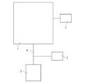
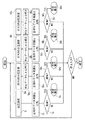
以下、本発明の真空排気監視装置の好ましい実施形態の一例を詳細に説明する。図1は、本発明の真空排気監視装置の概略図である。真空チャンバ1は真空装置の一部であり、真空装置として例えばスパッタリング装置や、PVD装置、CVD装置などの成膜装置、若しくはアッシング装置やドライエッチング装置などの電子デバイスの製造装置が挙げられるが、内部に真空チャンバを有する装置であれば特に制限されない。
Hereinafter, an example of a preferred embodiment of the evacuation monitoring apparatus of the present invention will be described in detail. FIG. 1 is a schematic view of a vacuum exhaustion monitoring device of the present invention. The
真空チャンバ1には排気経路4が設けられ、この排気経路4には真空ポンプ2が設けられており、真空ポンプ2の真空引きにより真空チャンバ1が真空となっていく。真空ポンプ2もロータリーポンプ、ターボ分子ポンプなど挙げられるが、特に制限はなく、使用状況に応じて大気圧から極高真空まで広い圧力範囲の真空引きに使用される真空ポンプである。
An
真空容器3は、真空チャンバ1の筐体に連設されるか、又は排気経路4に連設される。真空チャンバ1に直接連設した場合は、真空容器3内部に真空チャンバ1の真空が反映されやすいため、真空排気監視装置の構成として好適である。
The
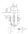
図2は、図1における真空容器3の構造を説明した説明図である。真空容器3は、内部に発光源5が収納され、発光源5からの光を透過する真空窓20が側壁の一部に設けられ、大気側から分光計測できるようになっており、このような機能を発揮できれば、その構成(材質・形状・大きさなど)は特に制限されない。本実施形態では真空容器3は筒状に形成され、その側面に直角方向に枝管7が設けられている。真空容器3内部は、枝管7を介して真空チャンバ1内部又は排気経路4内部と連通している。
FIG. 2 is an explanatory view illustrating the structure of the
図2に示すように、真空チャンバ1又は排気経路4には、真空容器3を連設するための連設手段が適宜設けられており、本実施形態では真空チャンバ1又は排気経路4から突設した枝管にフランジ8が設けられている。このフランジ8に対応して真空容器3にも連設手段が適宜設けられており、本実施形態では枝管7にフランジ9が設けられている。これらフランジ8、9はシール部材などを用いて気密に連設される。このため、真空容器3内部は外部に対して気密となって真空チャンバ1内部又は排気経路4内部と連通した真空が形成される。
As shown in FIG. 2, the
図2に示すように、真空容器3内部の一端側には、発光源5が収納されている。発光源5は、真空容器3内部に外部の大気側から分光計測可能な光であって、電極により生じる気体放電で気体分子又は気体原子を励起して気体圧力に依存した強度の光を発する発光源である。また発光源5において、気体の全圧を測定することができれば、さらに好適である。このため、本実施形態における発光源5は、プラズマ光を発光する発光源を有し、かつ気体の全圧計測も可能な冷陰極型電離真空計の発光源を使用している。
As shown in FIG. 2, a
図2に示すように、発光源5を発生させる冷陰極型電離真空計は陰極10と陽極11を有し、これらの間に放電空間12を形成するように配置され、自己放電により真空容器3内部の気体の電離を誘発してプラズマを発生させ、このプラズマの発光が発光源5となる。また、気体の放電を促進する磁性手段13と、気体全圧の測定圧力範囲を補う低真空計14も備えている。冷陰極型として電場と磁場が平行なペニング型、電場と磁場が直交するマグネトロン型、逆マグネトロン型などが知られており、実施に応じて形式は適宜選択されるが、本実施形態では、電子のトラップ効率が高く高真空領域においても安定した放電が持続可能な逆マグネトロン型を採用している。
As shown in FIG. 2, the cold cathode ionization vacuum gauge for generating the
陰極10は、略円筒状ないしは略管状を呈した金属部材のコールドカソード電極であり、本実施形態では底面部を有する測定子容器として真空容器3の側壁の一部となっている。陰極10の内周面に包囲された空間が、放電空間12となる。なお、陰極10の内周面に電極保護部材を設けたり、放電特性を改善する点火補助具を設けるなどしてもよい。
The
陽極11は、棒状を呈したアノード電極であり、その一端部側が絶縁部材を介して陰極10の底面部に気密に固定され、陰極10の中心軸上に位置するように放電空間12内に配設されている。陽極11の固定側は、所定の電圧を陽極10に印加する電源15や、放電電流を計測する放電電流メータ16などを有する動作回路(不図示)に接続され、接地されている。絶縁部材は、真空容器3内の真空環境に好適なテフロン(登録商標)、セラミックなどの誘電体絶縁破壊強度を備える材料で形成される。
The anode 11 is a rod-shaped anode electrode, one end of which is hermetically fixed to the bottom surface of the
磁性手段13は、放電空間12に磁場を発生させ電圧印加による陰極10からの放出電子の飛行を放電空間12内で持続させて気体の電離を促進する手段であり、その構成は実施に応じて適宜選択されるが、本実施形態では、陰極10の外周側(大気側)をリング状に包囲するように取付けられるマグネットとなっている。このマグネットは、フェライト磁石などの永久磁石であれば好適である。
The magnetic means 13 is means for generating a magnetic field in the
低真空計14は、発光源5の近傍に備えられている。上記のように本実施形態では、気体全圧の測定は、発光源5を発生させる冷陰極型電離真空計により計測されるため、高真空領域の全圧測定に制限される。広範囲な圧力領域で気体の全圧計測が必要となる場合(例えば半導体製造装置では10−4〜103Pa程度の範囲)は、真空計として互いに異なる測定範囲の複数の真空計を備え、必要に応じて所望の真空計の出力を選択できるように組み合わせて構成する必要があり、低真空計14は、低真空領域における気体の全圧測定を担う。また、所定の制御器17に接続されており、過渡域における自動切り替えや、飛越しやヒステリシス効果が発生しないような出力補正もされうる。
The
低真空計14は低真空領域の気体全圧計測ができれば特に制限はないが、本実施形態ではクリスタル真空計を使用しており、図示していないが、陽極11の根元部分に、音叉形に構成された水晶振動子が真空容器3内の気体を感知できるように組込まれて固定されている。クリスタル真空計は、原理的に熱源を有さないため高濃度酸素やオゾンなどの爆発性ガスにも安全に使用できると共に、大気圧においても安定して高精度な測定が可能であるため、低真空計(荒引き真空計)としてとくに好適である。
The
真空窓20は、真空容器3の側壁に気密に設けられ、真空側である発光源5からの計測対象となる波長のプラズマ光を外部の大気側へ透過させ、このプラズマ光を外部に設けられている光検出手段26で検出できるようにしている。真空窓20は、例えば単結晶アルミナ(サファイア)、水晶(溶融シリカ)などを材料として、透過するプラズマ光の散乱の低減や、表面付着物を抑制するような表面処理(フレーム研磨、ラッピング、削磨など)が施されうる。
The
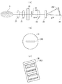
図3(イ)は、本発明の分光手段及び光検出手段を示している。分光手段は、発光源5からの光を集光して波長ごとの光に分光する手段である。光検出手段は、分光手段により分光された光の複数の波長強度を別個に検出し電気信号に変換する光センサである。本実施形態においては、分光手段は、真空窓20、集光レンズ21、22、収束レンズ23、スリット24、グレーティング25から構成され、光検出手段は、ピクセル状に配置された光電変換素子(CCD素子又はCMOS素子)から構成されている。
FIG. 3A shows the spectroscopic means and the light detecting means of the present invention. The spectroscopic means is means for condensing the light from the
集光レンズ21、22は所定の精度で光をコリメートし、収束レンズ23は、所定の精度で焦点に光を結像させる。スリット24は、光を所定領域に制限する集光領域限定手段であり、本実施形態では、図3(ロ)に示すように円板状の素材に中心に対照的に開口した細長い長方形240が形成されており、この長方形240を光が通過し、その他の部分で光をマスクするようになっている。長方形240の幅は、波長分解能やスループットなどを考慮して適宜選択される。本実施形態の長方形240のサイズは150μm×2.9mmである。グレーティング25は、光を所定の波長成分ごとに分光する手段であり、特に制限されないが、本実施形態では、透過回析格子を使用している。
The
図3(イ)に示すように、本実施形態の分光手段及び光検出手段の配置関係は、発光源5側(図3の左側)から順に集光レンズ21、収束レンズ23、真空窓20、スリット24、集光レンズ22、グレーティング25が配置され、光検出手段26(図3の右端)へプラズマ光が照射されるようになっている。真空窓20より左側は真空側(真空容器3内部)であり、真空窓20より右側は大気側(真空容器3外部)である。同図に示すように集光レンズ21を発光源5の隣近傍に配置すると、広い円錐角度で発光源5の光を集光できるため好適である。なお、この配置関係の一部として、真空窓20、集光レンズ21、収束レンズ23、スリット24は、図2にも示されている。
As shown in FIG. 3 (a), the arrangement of the spectroscopic means and the light detecting means of the present embodiment is such that the condensing
分光手段及び光検出手段の配置関係は、同図に示す配置関係に限らず、実施に応じて適宜変更できる。例えば図示していないが、真空側である真空容器3内部には発光源5の隣近傍にスリットのみを配置し、大気側である真空窓20外部に集光レンズ、収束レンズ、グレーティングを適宜配置してもよい。また、グレーティング25と光検出手段26との間に収束レンズをさらに設け、光検出手段26に波長ごとの光が集光されやすくなるようにするなど、レンズ、スリット、グレーティングの配置数を適宜増減させることもできる。さらに、分光手段及び光検出手段をすべて真空側(真空容器3内部)に設け、真空窓20を設けないように構成してもよい。
The arrangement relationship between the spectroscopic means and the light detection means is not limited to the arrangement relationship shown in FIG. For example, although not shown, only a slit is arranged in the vicinity of the
光検出手段26は、グレーティング25で波長ごとに分光された光を受光できるように、少なくともスリット24の長方形240の短辺方向(波長方向)と同じ方向に向けてCCD素子、CMOS素子などの光電変換素子が配列された受光部を備えたリニアアレイイメージセンサ(1次元イメージセンサ)、又は長方形240の長辺方向にも配列されたエリアアレイイメージセンサ(2次元イメージセンサ)である。このようなイメージセンサを光検出手段26に使用することで、波長ごとの光を別個にリアルタイムで計測することができる。受光部の素子がエリアアレイ(2次元配列)の場合、図3(ハ)に示すように、スリット24の長方形240の長辺方向と同程度の高さと、分光される波長範囲に対応した所定の幅を有する矩形状の長方形240の像260が投影される。この像260の外縁部分は、スリット24でマスクされたマスク部分の像に対応している。長方形240周辺のマスク部分の像をもリアルタイムにバックグラウンドとして測定するため、受光部の大きさは、像260より大きくなるように設けられる。
The light detection means 26 is a photoelectric device such as a CCD element or a CMOS element at least in the same direction as the short side direction (wavelength direction) of the
本発明のデータベース(不図示)には、気体成分に特有な光の波長の強度(光検出手段26の受光部で計測された光強度)と、気体分圧との関係を表す感度が記憶される。この感度は、種々の要因(気体成分、波長、時間など)に依存して変化し得るので、計測した光強度を正確な圧力に対応させる感度を使用できるようにするため、データベースにおいては、単なる定数としてでなく、依存する各要因に応じた変数として適切に管理される必要があると共に、素子や装置に固有の値なので、予め本発明の真空排気監視装置を使用した実験に基づく実測値を得ておく必要がある。 In the database (not shown) of the present invention, sensitivity representing the relationship between the intensity of the wavelength of light peculiar to the gas component (the light intensity measured by the light receiving unit of the light detection means 26) and the gas partial pressure is stored. The This sensitivity can vary depending on a variety of factors (gas component, wavelength, time, etc.), so in the database, the sensitivity can be used to match the measured light intensity to the exact pressure. Not only as a constant but also as a variable that depends on each dependent factor, and because it is a value inherent to the element or device, the actual measurement value based on the experiment using the vacuum exhaustion monitoring device of the present invention in advance is used. It is necessary to obtain it.
本実施形態では、この感度は、気体成分ごと、及びその気体成分に特有の波長ごとに記憶・管理される。その上で、光強度と圧力の数値対応表、又は光強度と圧力の適当な関数として記憶・管理される。 In the present embodiment, this sensitivity is stored and managed for each gas component and for each wavelength specific to the gas component. Then, it is stored and managed as a numerical correspondence table of light intensity and pressure, or an appropriate function of light intensity and pressure.
具体的には、光強度と圧力の数値対応表としての感度は、以下のようにしてデータベースに構成される。なお後述するように、この感度は実際の分圧計算のプロセスにおいても所定のサイクルタイムで順次更新される。
1.本発明の真空容器3に単一成分の気体(気体成分)を流入し一定の圧力に保つ
2.一定に保たれた真空容器3内の圧力を、校正済みの信頼できる別の真空計で計測する
3.上記2.と同時期に、発光源5の発光により本発明の光検出手段26で計測範囲内のすべての波長について、光強度を計測する
4.計測範囲内の波長から、その気体成分特有の波長を(1つ又は複数)適切に選択する
5.上記4.で選択された波長ごとに、光強度をデータベースに記憶する
6.上記1.において気体の圧力を変え、上記4.で選択されている全ての波長につき光強度をデータベースに記憶する
上記1.〜6.のプロセスを繰り返すことで、特定の気体成分ごとに、その気体成分に特有な光の波長として選択されている全ての波長について、特定の圧力における光強度の数値対応がデータベースに記憶される。したがって、気体成分を変更し、気体成分ごとに上記1.〜6.のプロセスを繰り返せば、例えば、気体成分に特有な波長ごとに圧力ごとに光強度が格納された数値対応のテーブルが、気体成分ごとに作成できる。
Specifically, the sensitivity as a numerical correspondence table of light intensity and pressure is configured in a database as follows. As will be described later, this sensitivity is sequentially updated at a predetermined cycle time even in the actual partial pressure calculation process.
1. 1. A single component gas (gaseous component) flows into the
また感度は、光強度と圧力の間の関数とすることもできる。すなわち光強度と圧力の間に適当に見出した関数で近似してもよい。感度をこのような関数とした場合は、データベースに記憶・管理されるデータ量が低減されデータ処理に好適である一方、良い近似精度となるよう適切に選択する必要がある。 Sensitivity can also be a function between light intensity and pressure. In other words, it may be approximated by a function found appropriately between the light intensity and the pressure. When the sensitivity is such a function, the amount of data stored and managed in the database is reduced and suitable for data processing, but it is necessary to select appropriately so as to obtain good approximation accuracy.
データ処理手段(不図示)は、データベースの感度、光検出手段26の計測する光強度、冷陰極型電離真空計や低真空計14からの全圧データに基づき、気体分圧の計算をするデータ処理がされる。また、真空容器3の異常診断やその結果をモニターに出力するなどのデータ処理も行われる。その他、必要な処理も適宜実装され得る。これらのデータ処理内容は後述する。
Data processing means (not shown) is a data for calculating the gas partial pressure based on the sensitivity of the database, the light intensity measured by the
次に、本発明の真空排気監視装置による気体成分の特定と、気体成分の分圧計算について説明する。上述したように、本発明の真空排気監視装置は低真空計14を備えているので、気体の分圧計測に基づく気体のモニタリングを、排気初期の荒引段階の早い時期から開始することができる。
Next, identification of the gas component and calculation of the partial pressure of the gas component by the evacuation monitoring apparatus of the present invention will be described. As described above, since the vacuum exhaust monitoring apparatus of the present invention includes the
まず、電源15より陽極11に所定の直流高電圧(例えば+2〜+3.5kV程度)を印加すると、放電空間12には、陽極11から陰極10へ向かう電場が発生すると共に、陰極10の電界放出や自然放射線等により放電空間12に飛行電子が発生する。この電子は、飛行中に気体原子・分子と様々な態様で衝突し、非弾性衝突の場合は気体分子を電離してイオン化する。また、磁性手段13により電場と垂直な方向へ磁場が発生しているため、放電空間12内の電子はローレンツ力により磁場の磁力線に巻付くように飛行し、放電空間12内での飛行が持続されて気体分子との衝突確率を高めることができる。また、気体分子と弾性衝突したり、衝突することがなかった飛行電子は、陽極11に到達する。このようにして、所定条件の下では、陰極10と陽極11との間の放電空間12にプラズマ状態の放電が維持される。
First, when a predetermined high DC voltage (for example, about +2 to +3.5 kV) is applied from the
この放電の持続中に、陽極11で電子を収集し、その電流値を放電電流メータ16で計測する。理論的に放電電流値と気体圧力は相関(比例関係)するので、この放電電流値から、気体の全圧を計測することができる。
During the discharge, electrons are collected by the anode 11 and the current value is measured by the discharge
また、放電電流強度と気体の圧力との関連が弱まり電極で全圧計測が困難となる低真空領域では、低真空計14により気体の全圧計測をするようにしている。
Further, in the low vacuum region where the relationship between the discharge current intensity and the gas pressure is weakened and it is difficult to measure the total pressure at the electrode, the gas total pressure is measured by the
一方で、電子と気体原子・分子の衝突により、気体原子・分子の主として最外殻の電子が高準位に励起された場合は、励起した電子が安定した低準位の軌道へ弛緩する際に、準位間のエネルギー差に対応した振動数の光子を放出することで、原子・分子(気体成分)に特有な波長を有する発光が生じる。このような電子遷移は様々な準位間で生じ得る。この発光強度の波長分布は(価電子)電子スペクトルなどと呼ばれ、主として可視光範囲内の波長範囲で計測され、原子・分子に特有なパターンとして不規則な間隔で輝線・帯線が並んだスペクトル状の分布となる。なお分子の場合は、主として赤外線領域で分子の振動準位による振動スペクトルや回転準位による回転スペクトルなどの微細構造も重なり合いスペクトルがさらに複雑化する。図2、3では、この発光による発光源5を示している。
On the other hand, when the electrons in the outermost shell of gas atoms / molecules are excited to a high level due to collisions between electrons and gas atoms / molecules, the excited electrons relax to a stable low-level orbit. In addition, emission of a photon having a frequency corresponding to the energy difference between the levels generates light having a wavelength that is unique to atoms and molecules (gas components). Such electronic transitions can occur between various levels. This wavelength distribution of emission intensity is called (valence electron) electron spectrum, etc., and is measured mainly in the wavelength range within the visible light range, and bright lines and band lines are arranged at irregular intervals as a pattern peculiar to atoms and molecules. It has a spectral distribution. In the case of molecules, fine spectra such as vibration spectra due to molecular vibration levels and rotation spectra due to rotation levels overlap in the infrared region, and the spectrum is further complicated. 2 and 3, the
また電子スペクトルの光強度は光子量と相関し、光子量は気体成分の物質量に相関し、気体成分の物質量は気体の圧力に相関するから、電子スペクトルの光強度は、気体成分の圧力に依存しているので、発光源5が発する光の強度は気体成分の圧力に依存している。
The light intensity in the electronic spectrum correlates with the photon amount, the photon amount correlates with the gas component substance amount, and the gas component substance amount correlates with the gas pressure. Therefore, the intensity of light emitted from the
発光源5からの光は、本実施形態では図2を用いて上記したように、まず集光レンズ21で集光され、収束レンズ23で真空窓20を透過してスリット24へ収束される。次いで、図3に示したように、集光レンズ22で集光され、グレーティング25で分光されて、光検出手段26に投影される。透過回析格子であるグレーティング25では、光の屈折率の違いを利用して、集光レンズ22でコリメートされたプラズマ光の入射角に対して、連続的に波長ごと所定の回析角度方向へ光を透過して分光するので、光は波長方向(長方形240短辺方向)に波長の大きさ順に整列して受光部に結像する。原子・分子(気体成分)に特有なプラズマ光の光強度は、波長に対して離散的(ピーク状やバンド状)に分布するため、受光部の結像は、図3(ロ)を用いて上述したように、波長方向にスペクトル状の矩形像260となる。
As described above with reference to FIG. 2 in the present embodiment, the light from the
光検出手段26の受光部には上記のように波長方向へ光電変換素子(CCD素子、CMOSアレイなど)が並べられているので、受光部の波長に対応した位置に配置された素子では受光した光子量に対応する電荷量が発生し、その電荷量は所定の光強度に対応した電気信号へ変換されることで、波長方向へ連続的に波長ごとに光の強度を同時に検出することができる。 As described above, photoelectric conversion elements (CCD elements, CMOS arrays, etc.) are arranged in the wavelength direction in the light receiving portion of the light detection means 26, so that light is received by the elements arranged at positions corresponding to the wavelength of the light receiving portion. A charge amount corresponding to the photon amount is generated, and the charge amount is converted into an electric signal corresponding to a predetermined light intensity, so that the light intensity can be detected simultaneously for each wavelength continuously in the wavelength direction. .
一方で、気体成分ごとの波長に対する光強度の分布(電子スペクトル)は図示していないが、これらは種々の気体成分(原子スペクトルや種々の分子・分子断片のスペクトル)固有の構造に基づいた気体成分ごとに特有なデータである。この気体成分ごとに特有である光強度分布のデータから、気体成分に特有な光強度を示す特定の波長を気体成分ごとに予め適切に選択しておき、その選択した波長を指標として検出光から気体成分が特定される。これらの波長は、なるべく他の気体成分について選択した波長と重複せず、かつ強度が明瞭なピーク状になる波長であれば気体成分の特定に好適であり、1つの気体成分に対して1つ以上選択される。また、これらの波長は、スペクトルデータベースなどにより従来から知られている波長から適切に選択され、さらに実験で新たに見出された波長からも適切に選択され得る。以下、具体的な原子・分子(気体成分)について、それぞれ好適な波長を挙げる。 On the other hand, the distribution of light intensity with respect to the wavelength of each gas component (electronic spectrum) is not shown, but these are gases based on the structures unique to various gas components (atomic spectra and spectra of various molecules and molecular fragments). The data is specific to each component. From the light intensity distribution data peculiar to each gas component, a specific wavelength indicating the light intensity peculiar to the gas component is appropriately selected in advance for each gas component, and the selected wavelength is used as an index from the detection light. A gas component is identified. These wavelengths are suitable for identifying a gas component as long as they are wavelengths that do not overlap with the wavelengths selected for other gas components as much as possible and have a clear intensity, and one for each gas component. These are selected. Further, these wavelengths are appropriately selected from conventionally known wavelengths using a spectrum database or the like, and can be appropriately selected from wavelengths newly found in experiments. Hereinafter, specific wavelengths are given for specific atoms and molecules (gas components).
酸素(O2)については、少なくとも777nm近辺、又は845nm近辺の波長のうち全部又は一部が選択される。 For oxygen (O 2 ), all or part of at least a wavelength around 777 nm or around 845 nm is selected.
窒素(N2)については、少なくとも424nm近辺、463nm近辺、747nm近辺、又は776nm近辺の波長のうち全部又は一部が選択される。 For nitrogen (N 2 ), all or part of at least a wavelength around 424 nm, around 463 nm, around 747 nm, or around 776 nm is selected.
水蒸気(H2O)については、少なくとも310nm近辺、486nm近辺、656nm近辺、777nm近辺、又は845nm近辺の波長のうち全部又は一部が選択される。 For water vapor (H 2 O), all or part of at least a wavelength around 310 nm, around 486 nm, around 656 nm, around 777 nm, or around 845 nm is selected.
ヘリウム(He)については、少なくとも502nm近辺、587nm近辺、587nm近辺、668nm近辺、又は728nm近辺の波長のうち全部又は一部が選択される。 For helium (He), all or part of at least a wavelength around 502 nm, around 587 nm, around 587 nm, around 668 nm, or around 728 nm is selected.
アルゴン(Ar)については、少なくとも697nm近辺、706nm近辺、738nm近辺、750nm近辺、764nm近辺、772nm近辺、795nm近辺、812nm近辺、又は844nm近辺の波長のうち全部または一部が選択される。 For argon (Ar), all or part of at least a wavelength around 697 nm, around 706 nm, around 738 nm, around 750 nm, around 764 nm, around 772 nm, around 795 nm, around 812 nm, or around 844 nm is selected.
水素(H2)については、少なくとも486nm近辺、又は656nm近辺の波長のうち全部又は一部が選択される。 For hydrogen (H 2 ), all or part of at least a wavelength around 486 nm or around 656 nm is selected.
一酸化炭素(CO)又は二酸化炭素(CO2)については、それぞれ少なくとも412nm近辺、516nm近辺、777nm近辺、又は845nm近辺の波長のうち全部または一部が選択される。 For carbon monoxide (CO) or carbon dioxide (CO 2 ), all or part of at least a wavelength around 412 nm, around 516 nm, around 777 nm, or around 845 nm is selected.
炭化水素系分子については、少なくとも412nm近辺、486nm近辺、516nm近辺、又は656nm近辺の波長のうち全部または一部が選択される。 For the hydrocarbon-based molecule, all or part of at least a wavelength around 412 nm, around 486 nm, around 516 nm, or around 656 nm is selected.
光検出手段26で波長方向へ連続的に波長ごとに同時に検出された光強度分布から、上記の気体成分に特有な光の波長として選択されている波長の光強度を計測することで、気体成分が特定される。 By measuring the light intensity of the wavelength selected as the wavelength of light peculiar to the above gas component from the light intensity distribution detected for each wavelength continuously in the wavelength direction by the light detection means 26, the gas component Is identified.
次いで、データ処理手段においては、上記のようにして計測された光強度と、データベースで記憶・管理されている感度とを対応させて、気体成分の分圧が計算される。この分圧計算は、以下1.〜7.のプロセスで行われる。
1.予め気体成分に特有な光の波長として選択されている波長(予めデータベースに記憶されている気体成分ごとの波長と同じ)ごとに、光強度を計測する
2.データベースに記憶されている感度(数値対応表又は関数)を使用して、その波長の(計測された)光強度に対応する圧力を、その気体成分の分圧とする(この際、選択されている波長が複数あり、それらの波長の(計測された)光強度に対応する圧力(気体成分の分圧)が、測定誤差などにより波長ごとに異なっている場合は、それらの圧力を平均化処理すれば、より精度の高い分圧が計算されるため好適である。また、信頼性の高い波長についてウェイトを重くした重み付平均化処理であればさらに好適である。)
3.上記2.の分圧を、気体成分の全種類について得て、それらの和をとり全圧(計算値)を得る
4.全圧真空計(低真空計14又は発光源5を有する冷陰極電離真空計)で気体の全圧(計測値)を得て、この全圧(計測値)と、上記3.で得た全圧(計算値)を比較する
5.上記4.で全圧(計測値)と全圧(計算値)が一致すれば、上記2.で得た分圧を、気体成分の分圧として出力する
6.上記4.で全圧(計測値)と全圧(計算値)が一致しなければ、全圧(計算値)が全圧(計測値)に一致するようにデータベースの感度を適宜補正する(以下、「全圧補正」という。)
7.上記6.に続いて、全圧補正後の感度を使用して、上記2.(分圧の計算)の結果を出力する
Next, in the data processing means, the partial pressure of the gas component is calculated by associating the light intensity measured as described above with the sensitivity stored and managed in the database. This partial pressure calculation is as follows: ~ 7. Done in the process.
1. 1. Measure the light intensity for each wavelength (same as the wavelength for each gas component stored in the database in advance) that is selected in advance as the wavelength of light specific to the gas component. Using the sensitivity (numerical correspondence table or function) stored in the database, the pressure corresponding to the (measured) light intensity of the wavelength is used as the partial pressure of the gas component (selected at this time). If there are multiple wavelengths and the pressure (partial pressure of the gas component) corresponding to the (measured) light intensity of those wavelengths differs for each wavelength due to measurement errors, etc., the pressures are averaged. This is preferable because a more accurate partial pressure is calculated, and a weighted averaging process in which a weight is increased for a highly reliable wavelength is more preferable.
3. 2. Is obtained for all kinds of gas components, and the sum of them is obtained to obtain the total pressure (calculated value). A total pressure (measured value) of gas is obtained by a total pressure vacuum gauge (a cold cathode ionization vacuum gauge having a
7). Above 6. Subsequent to the above-described 2. Output the result of ( Partial pressure calculation)
上記の全圧補正では、例えば全圧(計測値)を全圧(計算値)で除算して比を得て、この比を全圧(計算値)に使用された各気体成分の分圧に掛けて感度の圧力を更新する、などの処理がなされる。このように感度が更新されるので、感度(数値対応又は関数)の経時変化にも対応できる。 In the above total pressure correction, for example, the total pressure (measured value) is divided by the total pressure (calculated value) to obtain a ratio, and this ratio is used as the partial pressure of each gas component used for the total pressure (calculated value). Multiply processing such as renewing pressure of sensitivity. Since the sensitivity is updated in this way, it is possible to cope with a change in sensitivity (numerical value correspondence or function) with time.
上記プロセス1.〜7.は所定のサイクルタイム(例えば0.1秒〜数秒程度)ごとに処理されるので、気体成分ごとの分圧及び気体の全圧が所定時間ごとに(リアルタイムに)出力される。また、データベースの感度も、所定時間ごとに全圧(計測値)に基づいて更新されるので、実測値に基づき感度の正確性を順次高めていくことができる。
上記のように本実施形態では、種々の要因で変化し得る感度のパラメータとして、少なくとも気体種、波長、圧力をカバーし、しかも経時変化も全圧の実測値に基づいた全圧補正でカバーされる。したがって、高精度な分圧計算に基づく高水準な真空排気管理が実現できる。 As described above, in the present embodiment, at least the gas type, wavelength, and pressure are covered as sensitivity parameters that can change due to various factors, and changes with time are also covered by total pressure correction based on the actual measurement value of the total pressure. The Therefore, it is possible to realize a high level of evacuation management based on highly accurate partial pressure calculation.
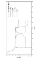
図4は本発明の真空排気監視において、上記のようにして得られた分圧及び全圧の出力画面例の説明図である。同図は圧力を対数表記した片対数グラフであり、冷陰極電離真空計の放電開始時点(約50Pa、図4においてはt=1.3min程度の時点)から、気体成分ごとの分圧と全圧の時間変化をリアルタイムで計測している。なお同図では、真空排気に漏洩が発生した異常排気状態を示しており、真空引きの開始からおよそ1分を過ぎたあたりで圧力の下がりが停まり、空気成分(窒素+酸素)が計測され分圧のほとんどを占めている。さらにおよそ3分の時点でヘリウムを吹き付けてリークテストを行ったところ空気に代わりヘリウムが上昇し、リーク箇所の特定ができたことを示す。その後およそ5分の時点で漏洩を止めた後には空気成分が減少し全圧も下がっている。このように、本発明の真空排気監視では、真空の漏洩の有無に加えて、成分分析に基づく異常診断が可能であるから、高水準な真空排気の管理が実現される。 FIG. 4 is an explanatory diagram of an example of an output screen of partial pressure and total pressure obtained as described above in the vacuum exhaust monitoring of the present invention. This figure is a semi-logarithmic graph in which the pressure is expressed in logarithm, and the partial pressure and the total pressure for each gas component from the discharge start time (about 50 Pa in FIG. 4 at about t = 1.3 min) of the cold cathode ionization vacuum gauge. The time change of pressure is measured in real time. The figure shows an abnormal exhaust state where leakage has occurred in the vacuum exhaust, and the pressure drop stops approximately 1 minute after the start of vacuuming, and the air component (nitrogen + oxygen) is measured. It accounts for most of the partial pressure. Furthermore, when a leak test was performed by blowing helium at about 3 minutes, helium rose instead of air, indicating that the leak location was identified. After about 5 minutes, after stopping the leak, the air component decreased and the total pressure decreased. As described above, in the evacuation monitoring according to the present invention, abnormality diagnosis based on component analysis is possible in addition to the presence or absence of leakage of vacuum, so that high-level evacuation management is realized.
続いて、本発明の真空排気監視装置による真空の異常診断について説明する。図5は、データ処理手段における異常診断の概略を説明したフローチャート図である。 Next, vacuum abnormality diagnosis by the vacuum exhaust monitoring apparatus of the present invention will be described. FIG. 5 is a flowchart for explaining an outline of abnormality diagnosis in the data processing means.
同図に示すように、本発明では、予め本発明の真空排気監視装置を使用して正常排気時の全圧及び気体成分ごとの分圧のそれぞれの圧力の時間変化を計測し、それらの正常時の圧力の時間変化を含む所定範囲の圧力の時間変化を正常時データ範囲として設定し、それらをデータベースに記憶しておく。そしてデータ処理手段において、実際の真空排気監視に使用して計測された排気の全圧データ又は気体成分ごとの分圧データを、データ処理手段により所定の時間ごとにそれぞれ正常時データ範囲と比較し、これら全圧データ又は分圧データが正常時データ範囲の範囲外であれば異常警報を出力するようにしている。 As shown in the figure, in the present invention, using the evacuation monitoring apparatus of the present invention, the time change of each of the total pressure during normal evacuation and the partial pressure for each gas component is measured in advance. A time variation of pressure within a predetermined range including a time variation of time pressure is set as a normal time data range and stored in a database. Then, in the data processing means, the exhaust total pressure data or the partial pressure data for each gas component measured and used for actual evacuation monitoring is compared with the normal data range for each predetermined time by the data processing means. If the total pressure data or the partial pressure data is outside the normal data range, an abnormal alarm is output.
このように本発明の異常診断では、全圧の異常診断と、気体成分ごとの分圧の異常判断とを並列的に、しかも所定時間ごとに繰り返し処理するため、高精度な真空状態のモニタリングと迅速な異常判断及び異常原因の特定が実現できる。また、装置の特性が反映された実際の実験データである正常時データに基づき異常・正常を判断するため、異常診断の正確性・信頼性を高めることができる。 As described above, in the abnormality diagnosis of the present invention, since the abnormality diagnosis of the total pressure and the abnormality determination of the partial pressure for each gas component are repeatedly processed in parallel and every predetermined time, high-precision vacuum state monitoring and It is possible to quickly determine the abnormality and identify the cause of the abnormality. In addition, since abnormality / normality is determined based on normal data that is actual experimental data reflecting the characteristics of the apparatus, the accuracy / reliability of abnormality diagnosis can be improved.
ステップS1では気体の全圧を測定し、ステップS2ではこの計測値と正常時データ範囲とを比較している。正常時データ範囲とは、例えば漏洩や内壁への気体の付着などがないなど、所定の基準状態にある真空チャンバ1に対して所定の真空ポンプ2で真空引きした際に、本発明の真空排気監視装置で計測された全圧に対して、その計測全圧値を含む所定範囲の圧力を設定したものであり、実施に応じて適宜設定される。ステップS3では計測全圧の異常判断がなされ、所定時間ごとに計測される計測全圧が正常時データ範囲内であれば正常判定とし、正常時データ範囲外であれば異常判定としてステップS4の異常表示へ処理を進めるようにしている。
Step S 1 measures the total pressure of the gas in, and comparing the normal state data range and the measured value in step S 2. The normal data range is, for example, when the
気体の分圧でも同様に、ステップSA1、SB1、SC1では、それぞれ単一の気体種A、B、Cについて分圧を計測している。気体種はこれらA、B、Cの3種に限られず、実施に応じて適宜増減される。ステップSA2、SB2、SC2では、前述の全圧補正がなされる。次いで、ステップSA3、SB3、SC3において正常時データ範囲との比較がなされ、ステップSA4、SB4、SC4においては計測分圧の異常判断がなされ、正常時データ範囲内であれば正常判定とし、正常時データ範囲外であれば異常判定としてステップSA5、SB5、SC5の異常表示が出力されるようになっている。 Similarly, in steps SA 1 , SB 1 , and SC 1 , partial pressures are measured for single gas species A, B, and C, respectively. The gas types are not limited to these three types of A, B, and C, and are appropriately increased or decreased depending on the implementation. In steps SA 2 , SB 2 , and SC 2 , the above-described total pressure correction is performed. Next, in steps SA 3 , SB 3 , and SC 3 , a comparison is made with the normal data range, and in steps SA 4 , SB 4 , and SC 4 , the measurement partial pressure is judged to be abnormal, and if it is within the normal data range. If the normal determination is made, and if it is out of the normal data range, the abnormality display of steps SA 5 , SB 5 and SC 5 is outputted as the abnormality determination.
図5に示すように、これらの処理は気体種ごと並列的に処理される。このため、上記の異常表示ステップでモニタに出力される異常表示は、単なる異常を知らせるアラーム表示のみならず、異常判定の起きた気体成分やそれらの組み合わせにより、予めプログラムされた所定の内容(例えば窒素、酸素に異常判定があった場合は、”漏れの可能性があります”といった内容)から診断結果に応じて適宜選択された異常表示とすることができる。したがって、高精度な真空排気監視ができる。 As shown in FIG. 5, these processes are performed in parallel for each gas species. For this reason, the abnormality display output to the monitor in the above-described abnormality display step is not only an alarm display notifying the abnormality, but also a predetermined content (for example, pre-programmed by a gas component in which abnormality determination has occurred or a combination thereof) If there is an abnormality determination for nitrogen or oxygen, it is possible to display an abnormality display appropriately selected according to the diagnosis result from “contents such as“ possibility of leakage ”). Therefore, highly accurate evacuation monitoring can be performed.
真空排気が異常となる場合(計測データが正常時データ範囲外となる場合)の原因として、例えば、大気圧の漏洩や透過、水蒸気や油脂等による汚れによる吸着成分の過多、通常は真空チャンバ内に存在しない物質成分の存在などが挙げられる。本発明の異常診断では、上記のように気体成分ごとの精密な監視に基づき、様々な排気異常の異常原因の診断が可能である。 Possible causes of abnormal evacuation (when the measurement data is outside the normal data range) include, for example, excessive atmospheric pressure leakage and permeation, excessive adsorption components due to contamination with water vapor, oil, etc., usually in the vacuum chamber The presence of substance components that are not present in In the abnormality diagnosis of the present invention, various causes of exhaust abnormality can be diagnosed based on precise monitoring for each gas component as described above.
全圧の時間変化のモニタリングにおいて、正常時データとして実験データ(実測値)の代わりに理論値を使用してもよい。この場合は以下に示すように、理論値として数1、2が使用される。数1は、真空チャンバのような一定体積の密閉空間から排気速度Sで真空引きした際の、内部の全圧の時間変化を示す方程式(排気曲線)である。数2は、数1の右辺第2項を示している。
In monitoring the time variation of the total pressure, theoretical values may be used as normal data instead of experimental data (actually measured values). In this case, as shown below,
![]()
![]()
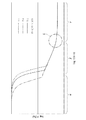
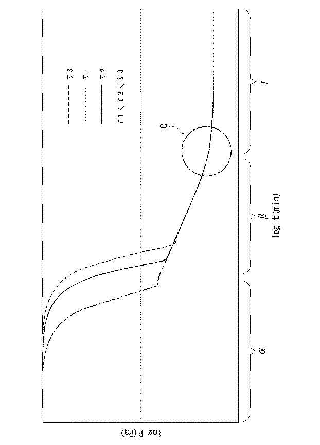
図6は、数1で示される排気曲線を両対数グラフにより現したものである。横軸目盛りは時間t(分)のlogt(min)、縦軸目盛りは圧力P(Pa)のlogP(Pa)であり、τは所定のパラメータである。排気曲線P(t)は、理論的には数1右辺の左から第1項、第2項、第3項の3つの項の和で表わされ、データベースに予め記憶されている。同図では、3つのτ1、τ2、τ3について排気曲線を例示しており、領域α、領域β、領域γは、横軸(時間軸)における第1項、第2項、第3項のそれぞれの支配領域を大まかに示している。
FIG. 6 is a double logarithmic graph representing the exhaust curve represented by Equation (1). The horizontal scale is logt (min) at time t (minutes), the vertical scale is log P (Pa) of pressure P (Pa), and τ is a predetermined parameter. The exhaust curve P (t) is theoretically represented by the sum of the three terms of the first term, the second term, and the third term from the left of the right side of
数1右辺第1項は、真空チャンバ内の、真空引き前から気化していた気体成分による圧力に対応している。第1項は指数関数的に減衰するので、同図に示すように、領域αにおいては圧力P(t)への寄与が支配的であるが、時間の経過と共に領域αから領域βへ移る附近で急速に減少し、領域βにおいてはほとんど無視できる項となる。
The first term on the right side of
数1右辺第2項は、水蒸気や揮発性の油分など真空チャンバ内の内壁に吸着していた吸着成分が真空引き開始後に真空が良くなってくるに従い順次脱離してくる脱離ガスによる圧力に対応している。この第2項は、理論的には数2に示したようにtのべき乗(−1)に比例した形で表わされる。このため第2項は、両対数グラフにおいては降下する直線(傾き45度)で表わされる。従って、第1項からの寄与が無視できる領域βにおいては、第2項からの寄与が支配的となり、排気曲線P(t)は降下する直線で示される。
The second term on the right side of
数1右辺第3項は、真空チャンバや排気経路などに発生している漏洩や透過に起因した圧力に対応している。この圧力は時間に対して殆ど一定の値であり第3項は定数とみなされる。従っていくら長時間を掛けてもこの圧力以下への真空引きが不可能となる。図6の排気曲線は、この第3項が無視できない程度に大きい異常排気時の排気曲線を示しており、第2項からの寄与が無視できる領域γにおいては、第3項からの寄与が支配的となり、排気曲線P(t)は水平線状で示される。
The third term on the right side of
真空排気が異常時の排気曲線の軌跡は、異常の原因に応じた特有のパターンを描くため、計測される全圧の排気曲線の軌跡を正常時の場合の排気曲線の軌跡と比較することで、迅速な異常の有無の検出と共に、様々な異常の原因を特定することができる。 Since the exhaust curve trajectory when the vacuum exhaust is abnormal draws a unique pattern according to the cause of the abnormality, the exhaust curve trajectory of the total pressure measured is compared with the exhaust curve trajectory when normal In addition to detecting the presence or absence of abnormalities quickly, various causes of abnormalities can be identified.
例えば漏洩や透過の値が正常時に比べて大きい排気異常時の場合では、第3項で示される定数部分の水平線は正常時に比べて大きくなり、圧力が45度の直線にしたがって降下する領域βから圧力が一定となる領域γに移行する時間が正常時に比べて早くなる。すなわちグラフ上の排気曲線P(t)の傾きが正常時に比べて早めに寝てくることになる。このため、通常の排気時間オーダーを示した図6では領域βと領域γの境界が現れ、この境界付近では両領域の排気曲線が下に凸状となった曲線で連結されている。円Cは、このように曲線が45度の傾きの直線から次第に剥離してくる排気曲線の部分を示している。 For example, in the case of exhaust abnormality when the leakage and permeation values are large compared to normal values, the horizontal line of the constant portion shown in the third term becomes larger than normal values, and from the region β where the pressure drops according to a straight line of 45 degrees. The time for shifting to the region γ where the pressure is constant is earlier than in the normal state. That is, the slope of the exhaust curve P (t) on the graph falls asleep earlier than in the normal state. For this reason, in FIG. 6 showing a normal exhaust time order, a boundary between the region β and the region γ appears, and the exhaust curves of both regions are connected by a curved line that protrudes downward near this boundary. A circle C shows an exhaust curve portion where the curve gradually peels off from a straight line having an inclination of 45 degrees.
一方で、正常排気時では、この第3項は装置の要求到達圧力に対して十分に小さいため事実上問題とならず、通常プロセスを開始するまでの排気時間(数100分まで)の範囲では、排気曲線P(t)は時間経過と共に傾き45度の直線で降下していく。このため、正常排気時の排気曲線は、図6に示す排気曲線と異なり、領域βと領域γの境界が現れず、領域βから領域γへと連続的に降下する直線状に現れる。 On the other hand, at the time of normal exhaust, this third term is sufficiently small with respect to the required pressure of the apparatus, so there is no practical problem. In the range of exhaust time (up to several hundred minutes) until the normal process starts. The exhaust curve P (t) descends with a straight line having an inclination of 45 degrees as time passes. Therefore, unlike the exhaust curve shown in FIG. 6, the exhaust curve during normal exhaust does not appear at the boundary between the region β and the region γ, and appears in a straight line that continuously falls from the region β to the region γ.
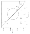
図7は、この場合の排気曲線P(t)の一例について、このような領域βと領域γの境界付近を拡大したグラフ図である。円Cは、図6と同様である。線Wは、水蒸気などの脱離ガスによる分圧の一例(数1の第2項)を示しており、同図においては45度に降下する直線である。線Nは、正常排気時における排気曲線の一部を示しており、この場合は、数1の第3項は装置の要求性能に比べて十分小さいので第2項からの寄与が支配的となる領域βから第3項からの寄与が支配的となる領域γへ移行するのは十分に長い時間の後である。このため同図では線Nは、線Wと同様に降下する直線状に現れている。なお、T1、T2、T3は、それぞれ所定のT1<T2<T3となる3時点の時間を示している。
FIG. 7 is an enlarged graph showing the vicinity of the boundary between the region β and the region γ with respect to an example of the exhaust curve P (t) in this case. Circle C is the same as in FIG. A line W shows an example of a partial pressure (second term of Equation 1) due to a desorption gas such as water vapor, and is a straight line that drops to 45 degrees in FIG. The line N shows a part of the exhaust curve during normal exhaust. In this case, the third term in
線Aは、漏洩や透過による異常排気時における排気曲線の一部を示しており、この場合は、数1の第3項が正常時と異なり装置の要求仕様に対して無視できない大きさとなっているため、上記したように、第2項が支配する直線状に降下する領域βから第3項が支配する領域γへの移行が正常時に比べて早く起こる。そのためにグラフ上では同図に示すように、時間経過とともに線Aは線Nより上側に乖離するように分岐する。
A line A shows a part of an exhaust curve at the time of abnormal exhaust due to leakage or permeation. In this case, the third term of
このように、理論値を使用した本発明の全圧監視による異常診断では、真空排気に漏洩や透過による異常が生じている場合は、時間経過と共に排気曲線が正常排気時の排気曲線から分岐(剥離)していくことに着目している。すなわち、正常排気時の排気曲線(図7では線N)に対する所定の圧力範囲を正常時データとして設定してデータベースに予め記憶しておき、データ処理手段において、この正常時データと計測した実際の全圧を比較し、異常がある場合は時間経過と共にグラフ上で排気曲線が分岐(剥離)していくので(図7では線A)、その分岐(剥離)を迅速に捉え、計測値が正常時データ範囲外となった場合は異常警報を出力するようにしている。理論値を使用した場合は、実験データの収集工程が省略されると共に、迅速な異常検知が実現され(図7では一例として約10分である)、排気曲線の分岐(剥離)の計測なので処理が簡略化されデータ処理に好適である。 As described above, in the abnormality diagnosis based on the total pressure monitoring according to the present invention using the theoretical value, when an abnormality due to leakage or permeation occurs in the vacuum exhaust, the exhaust curve branches off from the exhaust curve during normal exhaust over time ( We focus on peeling. That is, a predetermined pressure range with respect to the exhaust curve during normal exhaust (line N in FIG. 7) is set as normal time data and stored in advance in the database, and the data processing means measures the actual data measured with the normal time data. Comparing the total pressure, if there is an abnormality, the exhaust curve will branch (separate) on the graph as time passes (line A in FIG. 7). When it is outside the hour data range, an abnormal alarm is output. When theoretical values are used, the process of collecting experimental data is omitted, and rapid anomaly detection is realized (in FIG. 7, as an example, about 10 minutes). Is simplified and suitable for data processing.
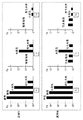
図8は、気体成分として窒素、酸素、水蒸気、及び炭化水素の4成分について、それぞれの分圧計測値を所定の3時点T1、T2、T3(図7のT1、T2、T3とそれぞれ対応している)につき棒グラフとした時間経過の一例であり、真空排気が正常時の場合と漏洩や透過による異常時の場合とを示している。 FIG. 8 shows measured partial pressure values of four components of nitrogen, oxygen, water vapor, and hydrocarbon as gas components at predetermined three time points T 1 , T 2 , T 3 (T 1 , T 2 , T 3 and an example of a bar graph with the time elapsed per each correspond), evacuation indicates the case of abnormal due to leakage or transmission to the case of normal.
図示するように時間T1においては、正常時と異常時の分圧に差異がない。時間T2においては、正常時では真空引きにより窒素と酸素が計測範囲外まで減少しているが、異常時では窒素と酸素の分圧が残存して計測されていると共に、正常時と異常時の水蒸気の分圧及び正常時と異常時の炭化水素の分圧にはほとんど差異が認められない。これらの点は、時間T3においても同様である。また、異常時の時間T2と時間T3のそれぞれの窒素と酸素の分圧にほとんど変化が認められない。 At time T 1, as shown, there is no difference in the partial pressure of the normal state and abnormal. At time T 2 , nitrogen and oxygen are reduced to outside the measurement range due to evacuation at normal time, but the partial pressure of nitrogen and oxygen is measured and measured at normal time and at normal time and abnormal time. There is almost no difference between the partial pressure of water vapor and the partial pressure of normal and abnormal hydrocarbons. These points are the same also in the time T 3. Also, little change in the partial pressure of each of nitrogen and oxygen in abnormal time T 2 and time T 3 is observed.
これは、これら4成分において、水蒸気と炭化水素の分圧については、それぞれ吸着分が真空引きの時間経過に伴い脱離してくる脱離ガスの分圧(数1の第2項に相当する)となっているので、正常時と異常時の時間変化に差異が出ないことによる。また一方で、窒素と酸素の分圧については、異常時、すなわち真空に漏洩があり所定圧力以下への真空引きができなくなっている場合は、透過ガスの分圧(数1の第3項に相当する)となるため、時間T2付近でそれぞれの分圧の下限値付近となった以降は減少することがなくなる。このため、異常時では少なくとも時間T2、T3では、正常時では計測されていない窒素と酸素の分圧が一定値付近で残存することになる。 This is because, in these four components, the partial pressures of water vapor and hydrocarbons are the partial pressures of the desorbed gas from which the adsorbed components are desorbed with the passage of time for evacuation (corresponding to the second term of Equation 1). This is because there is no difference in the time change between normal and abnormal. On the other hand, with regard to the partial pressure of nitrogen and oxygen, when there is an abnormality, that is, when there is leakage in the vacuum and it is impossible to evacuate to a predetermined pressure or less, the partial pressure of the permeating gas (in the third term of Equation 1) corresponding). Therefore, it is unnecessary to decrease since became near the lower limit of the respective partial pressures near the time T 2. For this reason, at the time T 2 and T 3 at the time of abnormality, the partial pressures of nitrogen and oxygen that are not measured at the normal time remain in the vicinity of a constant value.
上記のように、窒素と酸素の分圧計測によっても真空排気の漏洩や透過による排気異常の診断ができる。図8では、窒素と酸素の分圧における正常時と異常時の差異が、少なくとも時間T2において認められる。したがって少なくとも時間T2において正常時との比較から異常検知が可能となる。図7に示すように、この時間T2は一例として(全圧計測による場合と同様に)約10分程度である。 As described above, exhaust gas abnormality due to leakage or permeation of vacuum exhaust can also be diagnosed by measuring partial pressures of nitrogen and oxygen. In Figure 8, the difference in abnormal and normal in the partial pressure of nitrogen and oxygen is observed at least the time T 2. Thus it is possible anomaly detection from a comparison between the normal at least time T 2. As shown in FIG. 7, the time T 2 are (as in the case according to the total pressure measurement) as an example of the order of about 10 minutes.
また、上述したような漏洩や透過を原因とした排気異常時の場合のみならず、様々な異常原因の特定が可能である。 In addition to the case of exhaust abnormality due to leakage or permeation as described above, various causes of abnormality can be specified.
真空チャンバ内壁への水蒸気の吸着が通常時より多く、そのため脱離ガスが増加して真空排気が異常となっている場合は、図示していないが図8における時間T1、T2において水蒸気の分圧が正常時に比較して異常に大きく現れると共に、その大きい値を維持しながら時間T3に推移する。このため、水蒸気の分圧の監視により、時間T1又はT2(排気開始から早い経過時間)において水蒸気吸着の異常が検出できる。通常このような異常時は、真空チャンバを加熱して吸着した水蒸気を追い出すベーキングが必要となる。 In the case where the adsorption of water vapor to the inner wall of the vacuum chamber is more than usual, and therefore the desorbed gas increases and the evacuation becomes abnormal, although not shown, the water vapor is not absorbed at times T 1 and T 2 in FIG. with partial pressure appears unusually large compared to the normal, transitioning to time T 3 while maintaining its large value. For this reason, by monitoring the partial pressure of water vapor, an abnormality in water vapor adsorption can be detected at time T 1 or T 2 (early elapsed time from the start of exhaust). Usually, when such an abnormality occurs, baking is required to heat the vacuum chamber and drive off the adsorbed water vapor.
さらに水蒸気の吸着が多い異常時の排気曲線は、脱離ガス成分に対応する数1第2項が正常時より大きいため、図示していないが図7の領域β及び領域γにおいて、正常時の排気曲線である線Nを上方に平行移動したような軌跡となる。このため、この異常時の排気曲線の正常時の排気曲線からのずれを監視することで、全圧監視による水蒸気吸着の異常が迅速に検出できる。
Further, the exhaust curve at the time of abnormalities in which the adsorption of water vapor is large is not shown because the second term of
上記の漏洩や透過による異常、水蒸気吸着の異常の場合と同様に、種々の異常原因の特定が可能である。例えば、炭化水素の分圧を精密に監視し、正常時と比較して大きくなっていることを検出することで、真空チャンバ内の油脂等による汚れの異常が迅速に診断可能である。また、通常は真空チャンバ内に存在しない(あるいは存在しても極微量)気体成分の分圧の検出による異常診断も可能である。 As in the case of the abnormality due to leakage or permeation and the abnormality of water vapor adsorption, various causes of abnormality can be specified. For example, by accurately monitoring the partial pressure of hydrocarbon and detecting that it is larger than normal, it is possible to quickly diagnose an abnormality in dirt due to oil or the like in the vacuum chamber. Also, abnormality diagnosis is possible by detecting the partial pressure of a gas component that is not normally present in the vacuum chamber (or even if it exists).
以上説明したように、本発明の真空容器は、真空チャンバ又は排気経路に着脱自在に連設されるため取付け・取外しが容易で、排気の初期段階から監視が可能である。また、起動後は自動的に気体の全圧及び気体成分ごとの分圧が高精度かつリアルタイムに計測され、その計測データに基づいた自動的な異常診断が行われるインテリジェンス機能を備えたので、ユーザによらず簡単な操作で高水準な真空の健全性の監視・診断が実現できる。 As described above, the vacuum container of the present invention is detachably connected to the vacuum chamber or the exhaust path, so that it can be easily attached and removed, and can be monitored from the initial stage of exhaust. In addition, it has an intelligence function that automatically measures the total gas pressure and partial pressure for each gas component in real time with high accuracy and automatically diagnoses abnormalities based on the measurement data. Regardless of this, a high level of vacuum health monitoring and diagnosis can be achieved with simple operation.
更に、本発明は、前記実施の形態の記載に限定されるものではなく、本発明の特許請求の範囲に記載されている発明の要旨を逸脱しない範囲で種々の変更ができるものである。 Furthermore, the present invention is not limited to the description of the above embodiment, and various modifications can be made without departing from the spirit of the invention described in the claims of the present invention.
1 真空チャンバ
2 真空ポンプ
3 真空容器
4 排気経路
5 発光源
8、9 フランジ
10 陰極
11 陽極
12 放電空間
13 磁性手段
14 低真空計
16 放電電流メータ
20 真空窓
21、22 集光レンズ
23 収束レンズ
24 スリット
25 グレーティング
26 光検出手段
α、β、γ 時間領域
T1、T2、T3 時間
N 正常時の排気曲線
A 異常時の排気曲線
DESCRIPTION OF
Claims (1)
Priority Applications (1)
| Application Number | Priority Date | Filing Date | Title |
|---|---|---|---|
| JP2015050346A JP6613402B2 (en) | 2015-03-13 | 2015-03-13 | Vacuum exhaust monitoring device |
Applications Claiming Priority (1)
| Application Number | Priority Date | Filing Date | Title |
|---|---|---|---|
| JP2015050346A JP6613402B2 (en) | 2015-03-13 | 2015-03-13 | Vacuum exhaust monitoring device |
Publications (2)
| Publication Number | Publication Date |
|---|---|
| JP2016170072A JP2016170072A (en) | 2016-09-23 |
| JP6613402B2 true JP6613402B2 (en) | 2019-12-04 |
Family
ID=56983567
Family Applications (1)
| Application Number | Title | Priority Date | Filing Date |
|---|---|---|---|
| JP2015050346A Active JP6613402B2 (en) | 2015-03-13 | 2015-03-13 | Vacuum exhaust monitoring device |
Country Status (1)
| Country | Link |
|---|---|
| JP (1) | JP6613402B2 (en) |
Families Citing this family (5)
| Publication number | Priority date | Publication date | Assignee | Title |
|---|---|---|---|---|
| WO2019082893A1 (en) | 2017-10-24 | 2019-05-02 | 株式会社マルナカ | Gas analyzer |
| JP7080083B2 (en) * | 2018-03-27 | 2022-06-03 | 大阪瓦斯株式会社 | Calorific value measuring device and calorific value measuring method |
| JP6996630B2 (en) * | 2018-07-11 | 2022-01-17 | 株式会社島津製作所 | Emission analyzer and its maintenance method |
| US12085467B2 (en) | 2019-09-20 | 2024-09-10 | Inficon ag | Method for detecting pressure, and pressure sensor |
| JP2022063670A (en) * | 2020-10-12 | 2022-04-22 | 公立大学法人 滋賀県立大学 | Sensor device, low pressure space device and low pressure space system |
Family Cites Families (12)
| Publication number | Priority date | Publication date | Assignee | Title |
|---|---|---|---|---|
| DE2717436A1 (en) * | 1976-04-26 | 1977-11-10 | Varian Associates | METHOD AND DEVICE FOR DETERMINING THE PARTIAL PRESSURE OF A GAS FOR VACUUM MEASUREMENT, LEAK INDICATION, MEASUREMENT OF THE RATE OF PRECIPITATION OR THE DEGREE. |
| DE2732696A1 (en) * | 1977-07-20 | 1979-02-22 | Leybold Heraeus Gmbh & Co Kg | METHOD AND DEVICE FOR EVACUATING A RECIPIENT |
| JPH05215633A (en) * | 1992-02-06 | 1993-08-24 | Fujitsu Ltd | Device and method for monitoring vacuum device |
| FI98410C (en) * | 1993-12-16 | 1997-06-10 | Instrumentarium Oy | Measurement sensor and measuring device for analyzing gas mixtures |
| DE19505104A1 (en) * | 1995-02-15 | 1996-08-22 | Patent Treuhand Ges Fuer Elektrische Gluehlampen Mbh | Method and arrangement for determining the purity and / or pressure of gases for electric lamps |
| JP2000002660A (en) * | 1998-06-16 | 2000-01-07 | Shimadzu Corp | Film thickness calculation method in high frequency glow discharge emission spectroscopy |
| JP2003086574A (en) * | 2001-09-07 | 2003-03-20 | Mitsubishi Electric Corp | Gas analysis method for semiconductor processing apparatus and apparatus therefor |
| JP4078422B2 (en) * | 2003-08-29 | 2008-04-23 | 独立行政法人産業技術総合研究所 | Gas leak detection method and apparatus |
| JP4628807B2 (en) * | 2005-01-28 | 2011-02-09 | 株式会社日立ハイテクノロジーズ | Vacuum processing apparatus and vacuum processing method |
| JP2006294658A (en) * | 2005-04-06 | 2006-10-26 | Matsushita Electric Ind Co Ltd | Plasma processing equipment |
| JP5233131B2 (en) * | 2007-02-23 | 2013-07-10 | 株式会社Ihi | Carburizing apparatus and carburizing method |
| US9155831B2 (en) * | 2010-08-04 | 2015-10-13 | University Of Florida Research Foundation, Inc. | Apparatuses and methods for detecting gas contamination |
-
2015
- 2015-03-13 JP JP2015050346A patent/JP6613402B2/en active Active
Also Published As
| Publication number | Publication date |
|---|---|
| JP2016170072A (en) | 2016-09-23 |
Similar Documents
| Publication | Publication Date | Title |
|---|---|---|
| JP6613402B2 (en) | Vacuum exhaust monitoring device | |
| EP2951851B1 (en) | Method for mass spectrometric examination of gas mixtures and mass spectrometer therefor | |
| US8648293B2 (en) | Calibration of mass spectrometry systems | |
| US20230162967A1 (en) | Residual gas analyser, and euv lithography system having a residual gas analyser | |
| JP5987968B2 (en) | Discharge ionization current detector and adjustment method thereof | |
| US11791147B2 (en) | Mass spectrometer and method for analysing a gas by mass spectrometry | |
| WO2000017907A1 (en) | Apparatus and method for endpoint detection in non-ionizing gaseous reactor environments | |
| US6864982B2 (en) | Gas analyzing method and gas analyzer for semiconductor treater | |
| US20130032711A1 (en) | Mass Spectrometer | |
| US6975393B2 (en) | Method and apparatus for implementing an afterglow emission spectroscopy monitor | |
| CN1865975B (en) | Gas monitoring apparatus | |
| JP5669324B2 (en) | Quadrupole mass spectrometer | |
| US7355171B2 (en) | Method and apparatus for process monitoring and control | |
| KR20190075152A (en) | Composition emission spectroscopy for particle induced arc detection in manufacturing process | |
| TWI877242B (en) | Mass spectrometer and method for calibrating a mass spectrometer | |
| KR102140711B1 (en) | A hi-vacuum plasma residual gas analizer and method for analysing residua gas of the same | |
| JP2025026477A (en) | Gas analyzer and control method | |
| US12366552B2 (en) | Photoionization detector and method for gas sample analysis | |
| JPH10513566A (en) | Method and apparatus for measuring purity and / or pressure of gas for bulbs | |
| US7989761B2 (en) | Gas analyzing method and gas analyzing apparatus | |
| WO2021251026A1 (en) | Observation device for gas under observation, method of observing ions under observation, and sample holder | |
| JP4028723B2 (en) | Thermal desorption gas analyzer using electron attachment mass spectrometry and analysis method | |
| JP4199050B2 (en) | Quadrupole mass spectrometer and vacuum apparatus having the same | |
| JP2001250812A (en) | End point detection method and end point detection device for plasma processing | |
| WO2002023160A1 (en) | Afterglow emission spectroscopy monitor |
Legal Events
| Date | Code | Title | Description |
|---|---|---|---|
| A621 | Written request for application examination |
Free format text: JAPANESE INTERMEDIATE CODE: A621 Effective date: 20180312 |
|
| A977 | Report on retrieval |
Free format text: JAPANESE INTERMEDIATE CODE: A971007 Effective date: 20190123 |
|
| A131 | Notification of reasons for refusal |
Free format text: JAPANESE INTERMEDIATE CODE: A131 Effective date: 20190205 |
|
| A521 | Request for written amendment filed |
Free format text: JAPANESE INTERMEDIATE CODE: A523 Effective date: 20190405 |
|
| TRDD | Decision of grant or rejection written | ||
| A01 | Written decision to grant a patent or to grant a registration (utility model) |
Free format text: JAPANESE INTERMEDIATE CODE: A01 Effective date: 20190820 |
|
| A61 | First payment of annual fees (during grant procedure) |
Free format text: JAPANESE INTERMEDIATE CODE: A61 Effective date: 20190904 |
|
| R150 | Certificate of patent or registration of utility model |
Ref document number: 6613402 Country of ref document: JP Free format text: JAPANESE INTERMEDIATE CODE: R150 |
|
| R250 | Receipt of annual fees |
Free format text: JAPANESE INTERMEDIATE CODE: R250 |
|
| R250 | Receipt of annual fees |
Free format text: JAPANESE INTERMEDIATE CODE: R250 |