JP5987968B2 - Discharge ionization current detector and adjustment method thereof - Google Patents
Discharge ionization current detector and adjustment method thereof Download PDFInfo
- Publication number
- JP5987968B2 JP5987968B2 JP2015500053A JP2015500053A JP5987968B2 JP 5987968 B2 JP5987968 B2 JP 5987968B2 JP 2015500053 A JP2015500053 A JP 2015500053A JP 2015500053 A JP2015500053 A JP 2015500053A JP 5987968 B2 JP5987968 B2 JP 5987968B2
- Authority
- JP
- Japan
- Prior art keywords
- helium
- helium gas
- discharge
- light
- current detector
- Prior art date
- Legal status (The legal status is an assumption and is not a legal conclusion. Google has not performed a legal analysis and makes no representation as to the accuracy of the status listed.)
- Expired - Fee Related
Links
Images


Classifications
-
- G—PHYSICS
- G01—MEASURING; TESTING
- G01N—INVESTIGATING OR ANALYSING MATERIALS BY DETERMINING THEIR CHEMICAL OR PHYSICAL PROPERTIES
- G01N27/00—Investigating or analysing materials by the use of electric, electrochemical, or magnetic means
- G01N27/62—Investigating or analysing materials by the use of electric, electrochemical, or magnetic means by investigating the ionisation of gases, e.g. aerosols; by investigating electric discharges, e.g. emission of cathode
- G01N27/68—Investigating or analysing materials by the use of electric, electrochemical, or magnetic means by investigating the ionisation of gases, e.g. aerosols; by investigating electric discharges, e.g. emission of cathode using electric discharge to ionise a gas
- G01N27/70—Investigating or analysing materials by the use of electric, electrochemical, or magnetic means by investigating the ionisation of gases, e.g. aerosols; by investigating electric discharges, e.g. emission of cathode using electric discharge to ionise a gas and measuring current or voltage
-
- G—PHYSICS
- G01—MEASURING; TESTING
- G01N—INVESTIGATING OR ANALYSING MATERIALS BY DETERMINING THEIR CHEMICAL OR PHYSICAL PROPERTIES
- G01N30/00—Investigating or analysing materials by separation into components using adsorption, absorption or similar phenomena or using ion-exchange, e.g. chromatography or field flow fractionation
- G01N30/02—Column chromatography
- G01N30/62—Detectors specially adapted therefor
- G01N30/64—Electrical detectors
Description
本発明は、主としてガスクロマトグラフ(GC)用の検出器として好適な放電イオン化電流検出器及びその調整方法に関し、更に詳しくは、検出器による測定結果の精度や再現性の改善に関する。 The present invention mainly relates to a discharge ionization current detector suitable as a detector for a gas chromatograph (GC) and a method for adjusting the same, and more particularly to improvement in accuracy and reproducibility of measurement results obtained by the detector.
GC用の検出器としては、水素炎イオン化検出器(FID:Flame Ionization Detector)、熱伝導度検出器(TCD:Thermal Conductivity Detector)、電子捕捉型検出器(ECD:Electron Capture Detector)の他、放電を利用した、パルス放電イオン化電流検出器(PDD:Pulsed Discharge Detector)、低周波誘電体バリア放電イオン化電流検出器(BID:dielectric Barrier discharge Ionization Detector)等、様々な方式の検出器が従来から実用に供されている。 GC detectors include flame ionization detectors (FID), thermal conductivity detectors (TCDs), electron capture detectors (ECDs), and discharges. Various types of detectors such as pulse discharge ionization current detector (PDD) and low-frequency dielectric barrier discharge ionization current detector (BID) that have been used in the past have been put to practical use. It is provided.
検出器の中で、有機物を検出するために一般的に使用されているのはFIDである。FIDは、水素炎により試料ガス中の試料成分をイオン化し、そのイオン電流を検出する。FIDは、ダイナミックレンジが広いという特徴を有するが、試料成分を水素炎で燃焼させてイオン化するため、難燃焼性ガスや無機ガスに対する感度は低く、分析対象となる化合物が限定される。 Among detectors, FID is commonly used to detect organic matter. The FID ionizes sample components in the sample gas with a hydrogen flame and detects the ion current. Although FID has a wide dynamic range, it is ionized by burning sample components with a hydrogen flame, and therefore, the sensitivity to incombustible gas and inorganic gas is low, and the compound to be analyzed is limited.
一方、電極への高電圧パルス印加による放電でヘリウムガス等を励起してプラズマを生成し、該プラズマの発光(真空紫外光等)を利用して試料をイオン化するPDDは、難燃焼性ガスや無機ガスに対しても高い感度を有し、ガスクロマトグラフに要求されるほぼ全ての化合物の検出に適する。しかしながら、PDDのダイナミックレンジはFIDに及ばない。その要因は、PDDでは放電が安定せず、プラズマ状態が変動するためと考えられる(例えば特許文献1参照)。 On the other hand, a PDD that excites helium gas or the like by discharge by applying a high voltage pulse to an electrode to generate plasma and ionizes a sample using light emission of the plasma (vacuum ultraviolet light or the like) is a flame-retardant gas or It has high sensitivity to inorganic gases and is suitable for detecting almost all compounds required for gas chromatographs. However, the dynamic range of PDD does not reach FID. The reason is considered that the discharge is not stable in PDD and the plasma state fluctuates (for example, see Patent Document 1).
これに対し、誘電体で囲んだ空間を設け、該誘電体の外側に形成した放電用電極に交流の低周波電圧を印加することで、該空間内にプラズマを生成するBIDでは、PDDよりも放電が安定し、プラズマ状態の変動が抑えられる。これは、放電用電極とプラズマを誘電体バリア(合成石英等)で分離することで、該放電用電極がプラズマに晒されることがなく、スパッタ粒子や吸着されているガス分子の放出を防ぐことができ、また、低周波電圧(周波数が5〜50kHz程度、振幅が数kV程度)により生成したプラズマは、PDDの高電圧パルス(周波数が数MHz、振幅が数kV程度)により生成した場合よりもプラズマ温度が低く、検出器の内壁材料の加熱による不純物ガスの発生を抑えることができるためと考えられる。その結果、BIDは安定性に優れ、長期に亘り良好なSN比が得られる(例えば特許文献1から5参照)。
On the other hand, in a BID that generates a plasma in the space by providing a space surrounded by a dielectric and applying an alternating low frequency voltage to a discharge electrode formed outside the dielectric, a PD is more than a PDD. Discharge is stabilized and fluctuations in plasma state are suppressed. This is because the discharge electrode and plasma are separated by a dielectric barrier (synthetic quartz, etc.), so that the discharge electrode is not exposed to plasma and prevents the release of sputtered particles and adsorbed gas molecules. In addition, plasma generated by low-frequency voltage (frequency is about 5-50kHz, amplitude is about several kV) is higher than that generated by PDD high-voltage pulse (frequency is several MHz, amplitude is about several kV). This is also because the plasma temperature is low and generation of impurity gas due to heating of the inner wall material of the detector can be suppressed. As a result, BID has excellent stability, good SN ratio for a long time can be obtained (see, for example 5 from Patent Document 1).
上述のとおり、放電イオン化電流検出器においては、放電を安定化することが重要である。BIDでは、上述のように比較的安定した放電が得られるが、実際の使用においては様々な要因により検出結果にバラツキが生じ、測定の精度や再現性が低下してしまう。 As described above, it is important to stabilize the discharge in the discharge ionization current detector. With BID, a relatively stable discharge can be obtained as described above. However, in actual use, detection results vary due to various factors, and measurement accuracy and reproducibility are reduced.
本願発明は、上記課題を解決するために成されたものであり、その目的とするところは、測定の精度や再現性の低下を防ぐことを可能とした放電イオン化電流検出器を提供することである。 The present invention has been made to solve the above-mentioned problems, and the object of the present invention is to provide a discharge ionization current detector capable of preventing a decrease in measurement accuracy and reproducibility. is there.
ヘリウムガスに含まれる微量の不純物により、放電の状態が変化するので、例えばPDDにおいても、純度の高いガスを使用することが推奨されている。しかし様々な要因により混入する不純物量を、常にコントロールすることは困難である。したがって、検出器性能を安定に保つには、試料イオン化を行っている真空紫外光の光量を直接測定するのが理想である。しかし、波長200nm以下の真空紫外光を直接測定するためには、高価・大型の真空紫外用分光装置を使う必要がある。 Since the state of discharge changes due to a small amount of impurities contained in the helium gas, it is recommended to use a high-purity gas even in PDD, for example. However, it is difficult to always control the amount of impurities mixed due to various factors. Therefore, in order to keep the detector performance stable, it is ideal to directly measure the amount of vacuum ultraviolet light that is performing sample ionization. However, in order to directly measure vacuum ultraviolet light with a wavelength of 200 nm or less, it is necessary to use an expensive and large-sized vacuum ultraviolet spectrometer.
本願発明者らは、様々な実験を行い、放電によりヘリウムガスを励起して生成したプラズマにおいては、真空紫外光(波長10〜200nm)よりも長波長である250〜700nmの波長範囲の発光スペクトルから、真空紫外光の発光状態を判断できることを見いだした。 The inventors of the present application conducted various experiments, and in the plasma generated by exciting the helium gas by discharge, the emission spectrum in the wavelength range of 250 to 700 nm, which is longer than the vacuum ultraviolet light (wavelength of 10 to 200 nm). From this, it was found that the emission state of vacuum ultraviolet light can be judged.
BIDのヘリウムプラズマの発光スペクトルでは、250〜700nmの波長範囲に、ヘリウム分子イオン(He2 +)の輝線を示す640nmの成分とヘリウム原子の輝線を示す588nm及び707nmの成分が含まれる。その他には、不純物として、酸素分子の発光を示す533nm及び544nmの成分や水素原子の発光を示す656nmの成分などが含まれる。ここで、ヘリウム分子イオン(He2 +)はヘリウムプラズマ中のヘリウム原子の衝突により生成されるが、その生成は主に以下に述べる3体衝突によって行われる。3体衝突は、まず2体衝突によって不安定なヘリウム分子(He2)が生成され、該ヘリウム分子(He2)が存在する短時間のうちに、さらに別のヘリウム原子が衝突することで、安定なヘリウム分子イオン(He2 +)が生成される過程である。このような3体衝突の頻度は、ヘリウムプラズマ中の不純物濃度が高くなるにつれて指数関数的に(すなわち三乗に比例して)減少する。そのため、不純物が微量であっても、ヘリウムプラズマが発する640nmの輝線強度は小さく且つ不安定になる。
そこで、ヘリウム分子イオン(He2 +)による640nmの輝線強度を指標とすることで、ヘリウムプラズマ中の微量不純物の存在、ひいては真空紫外光の発光状態を判断することができる。In the emission spectrum of the helium plasma of BID, a wavelength range of 250 to 700 nm includes a component of 640 nm indicating the emission line of helium molecular ions (He 2 + ) and a component of 588 nm and 707 nm indicating the emission line of helium atoms. In addition, impurities include 533 nm and 544 nm components that emit oxygen molecules, 656 nm component that emits hydrogen atoms, and the like. Here, helium molecular ions (He 2 + ) are generated by collision of helium atoms in helium plasma, and the generation is mainly performed by three-body collision described below. In a three-body collision, an unstable helium molecule (He 2 ) is first generated by a two-body collision, and another helium atom collides in a short time in which the helium molecule (He 2 ) exists. This is a process in which stable helium molecular ions (He 2 + ) are generated. The frequency of such three-body collisions decreases exponentially (that is, in proportion to the third power) as the impurity concentration in the helium plasma increases. Therefore, even if the amount of impurities is very small, the intensity of the emission line at 640 nm emitted by helium plasma is small and unstable.
Therefore, by using the intensity of the emission line at 640 nm by helium molecular ions (He 2 + ) as an index, it is possible to determine the presence of a trace amount of impurities in the helium plasma and the emission state of vacuum ultraviolet light.
このような、従来になかった640nmの輝線強度を指標にするという新たな知見のもと、本願発明者らが検討したところ、250〜700nmの波長範囲において波長が640nmの輝線強度が他の波長の各輝線強度よりも大きくなる発光スペクトルを有するヘリウムプラズマが、光量が大きくかつ安定した真空紫外光を発することがわかった。 Based on this new knowledge that the 640 nm emission line intensity, which has not been used in the past, as an index, the inventors of the present application have studied, and in the wavelength range of 250 to 700 nm, the emission line intensity of 640 nm has other wavelengths. It has been found that helium plasma having an emission spectrum larger than the intensity of each emission line emits a vacuum ultraviolet light having a large amount of light and stable.
すなわち、本発明に係る放電イオン化電流検出器の調整方法は、低周波誘電体バリア放電により生成したヘリウムプラズマを利用する放電イオン化電流検出器において、該ヘリウムプラズマが発する250〜700nmの波長範囲の光の中で640nmの光の強度が最大となるように、導入するヘリウムガスの純度、導入するヘリウムガスの流量、低周波誘電体バリア放電における電圧の振幅、及び、低周波誘電体バリア放電における電圧の周波数の少なくとも1つを調整する。 That is, the discharge ionization current detector adjustment method according to the present invention is a discharge ionization current detector using helium plasma generated by a low-frequency dielectric barrier discharge, and light in a wavelength range of 250 to 700 nm emitted by the helium plasma. In order to maximize the intensity of light at 640 nm, the purity of the introduced helium gas, the flow rate of the introduced helium gas, the amplitude of the voltage in the low-frequency dielectric barrier discharge, and the voltage in the low-frequency dielectric barrier discharge Adjust at least one of the frequencies.
この調整方法では、導入するヘリウムガスの純度、流量、低周波誘電体バリア放電における電圧の振幅、周波数を調整することで、ヘリウムプラズマが発する250〜700nmの波長範囲の光の中で640nmの光の強度(輝線強度)が最大となるようにする。このような調整が可能な理由は、これらの条件がいずれも640nmの輝線強度を左右するためである。導入するヘリウムガスの純度はヘリウムプラズマ中の不純物濃度に関係するため、ヘリウム原子同士の3体衝突によるヘリウム分子イオン(He2 +)の生成量、すなわち波長が640nmの輝線強度を左右する。また、導入するヘリウムガスの流量は、ヘリウムの数密度(単位は例えば「原子数/cm3」)に関係するため、波長が640nmの輝線強度を左右する。さらに、低周波誘電体バリア放電における電圧の振幅及び周波数は、ヘリウムプラズマを生成する励起電力に関係するため、ヘリウムプラズマの発光状態、すなわち波長が640nmの輝線強度を左右する。In this adjustment method, by adjusting the purity and flow rate of helium gas to be introduced, the amplitude and frequency of the voltage in the low-frequency dielectric barrier discharge, light of 640 nm among light in the wavelength range of 250 to 700 nm emitted by helium plasma. The intensity (bright line intensity) is maximized. The reason why such adjustment is possible is that all of these conditions affect the intensity of the emission line at 640 nm. Since the purity of the introduced helium gas is related to the impurity concentration in the helium plasma, the amount of helium molecular ions (He 2 + ) generated by the three-body collision between helium atoms, that is, the intensity of the emission line having a wavelength of 640 nm is affected. Further, since the flow rate of the introduced helium gas is related to the number density of helium (the unit is, for example, “number of atoms / cm 3 ”), it influences the intensity of the emission line having a wavelength of 640 nm. Furthermore, since the amplitude and frequency of the voltage in the low-frequency dielectric barrier discharge are related to the excitation power for generating the helium plasma, the emission state of the helium plasma, that is, the intensity of the emission line having a wavelength of 640 nm is affected.
また、上記調整方法に対応する放電イオン化電流検出器は、低周波誘電体バリア放電により生成したヘリウムプラズマを利用する放電イオン化電流検出器であって、
a)ヘリウムガスを導入するヘリウムガス導入部と、
b)低周波誘電体バリア放電に用いる放電用電極に印加する低周波電圧の振幅あるいは周波数を調整する電圧調整部と、
c)ヘリウムプラズマが発する250〜700nmの波長範囲の光の波長毎の強度を検出する光検出部と、
d)前記波長範囲中、640nmの光の強度が最大となるように、前記電圧調整部を制御する制御部と
を備える。
導入するヘリウムガスの純度及び流量は、予め実験を行っておくことで定めることができるが、さらにそれらを調整可能とするため、上記放電イオン化電流検出器において、
e)導入するヘリウムガスの純度を調整するヘリウムガス純度調整部と、
f)導入するヘリウムガスの流量を調整するヘリウムガス流量調整部とをさらに備え、
前記制御部が、前記波長範囲中、640nmの光の強度が最大となるように、前記ヘリウムガス純度調整部、及び、前記ヘリウムガス流量調整部の少なくとも一つを制御するようにしてもよい。The discharge ionization current detector corresponding to the adjustment method is a discharge ionization current detector using helium plasma generated by a low-frequency dielectric barrier discharge,
a) a helium gas introduction part for introducing helium gas;
b) a voltage adjusting unit for adjusting the amplitude or frequency of the low frequency voltage applied to the discharge electrode used for the low frequency dielectric barrier discharge;
c) a light detection unit for detecting the intensity for each wavelength of light in the wavelength range of 250 to 700 nm emitted by helium plasma;
d) including a control unit that controls the voltage adjusting unit so that the intensity of light at 640 nm is maximized in the wavelength range.
The purity and flow rate of the helium gas to be introduced can be determined by conducting experiments in advance, but in order to further adjust them,
e) a helium gas purity adjusting unit for adjusting the purity of helium gas to be introduced;
f) further comprising a helium gas flow rate adjusting unit for adjusting the flow rate of the helium gas to be introduced,
The control unit may control at least one of the helium gas purity adjustment unit and the helium gas flow rate adjustment unit so that the intensity of light at 640 nm is maximized in the wavelength range.
上記において、ヘリウムガスの純度及び流量が予め定められている場合には、更に、低周波誘電体バリア放電に用いる放電用電極に印加する低周波電圧の振幅及び周波数を予め適切な条件に定めておくことで、ヘリウムプラズマが発する250〜700nmの波長範囲中、640nmの光の強度が最大となるようにすることができる。
この場合、上記の制御部は不要となる。低周波誘電体バリア放電の電圧の振幅及び周波数の適切な条件は、予め実験を行っておくことで定めることができる。In the above, when the purity and flow rate of helium gas are determined in advance, the amplitude and frequency of the low frequency voltage applied to the discharge electrode used for the low frequency dielectric barrier discharge are further determined in appropriate conditions. Thus, the intensity of light at 640 nm can be maximized in the wavelength range of 250 to 700 nm emitted by helium plasma.
In this case, the control unit is not necessary. Appropriate conditions for the amplitude and frequency of the voltage of the low-frequency dielectric barrier discharge can be determined by conducting experiments in advance.
低周波誘電体バリア放電に用いる放電用電極に印加する低周波電圧の振幅及び周波数が予め定められている場合にも、更に、ヘリウムガスの純度又は流量を予め適切な条件に定めておくことで、ヘリウムプラズマが発する250〜700nmの波長範囲中、640nmの光の強度が最大となるようにすることができる。 Even when the amplitude and frequency of the low-frequency voltage applied to the discharge electrode used for the low-frequency dielectric barrier discharge are determined in advance, the purity or flow rate of the helium gas should be determined in advance under appropriate conditions. In the wavelength range of 250 to 700 nm emitted by helium plasma, the intensity of light at 640 nm can be maximized.
或いは、上述の制御部において、更に、640nmの光の強度が一定となるように前記電圧調整部を制御するようにしてもよい。 Alternatively, in the above-described control unit, the voltage adjustment unit may be further controlled so that the intensity of light at 640 nm is constant.
このような制御により、真空紫外光の発光状態をさらに安定させることが可能となる。 Such control makes it possible to further stabilize the emission state of vacuum ultraviolet light.
本発明の放電イオン化電流検出器の調整方法によれば、従来よりも光量が大きくかつ安定した真空紫外光を発するヘリウムプラズマを生成することで、測定の精度及び再現性を向上させた放電イオン化電流検出器を得ることができる。 According to the method for adjusting a discharge ionization current detector of the present invention, the discharge ionization current has improved measurement accuracy and reproducibility by generating helium plasma that emits vacuum ultraviolet light having a larger light amount and more stable than the conventional one. A detector can be obtained.
以下、本発明の実施例について図面を参照しつつ説明する。 Embodiments of the present invention will be described below with reference to the drawings.
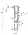
図1は、本発明の放電イオン化電流検出器の調整方法(以下単に「本調整方法」という場合がある)により調整を行うための放電イオン化電流検出器であり、略円筒形状をした放電イオン化電流検出器10の断面を示す。この放電イオン化電流検出器10は、本発明の一実施例による放電イオン化電流検出器でもあり、主にプラズマ生成部20とイオン収集部30で構成される。
FIG. 1 is a discharge ionization current detector for adjusting according to a method for adjusting a discharge ionization current detector of the present invention (hereinafter sometimes simply referred to as “the present adjustment method”), and a discharge ionization current having a substantially cylindrical shape. The cross section of the
プラズマ生成部20の上方にはヘリウム(He)ガスを導入するためのガス導入口21を設け、その下方には誘電体部材で形成した円筒管24を設ける。さらに、円筒管24の下方にはヘリウムガスを排出するための排出口28を設ける。ガス導入口21はバルブ22を介してヘリウム精製器23と接続する。ヘリウム精製器23はヘリウムボンベ(図示しない)から送られたヘリウムガス中の不純物を取り除き、高純度のヘリウムガスを精製して導入口21に供給するためのものであり、要求されるヘリウムガスの純度に応じて適切な純度を選択できるようにしておく。バルブ22は、ヘリウム精製器23からガス導入口21に送られるヘリウムガスの流量を制御し、プラズマ生成部20の内部におけるヘリウムプラズマの密度を変えることができるよう、開度を調整できるようにしておく。円筒管24は誘電体で形成する。誘電体がヘリウムプラズマに晒されると、表面から不純物が放出されるが、不純物の放出量は誘電体材料の選択によりコントロールできる。そこで、円筒管24の誘電体材料は適宜交換できるようにしておく。円筒管24の外側には放電用電極25を配置し、該放電用電極25には交流電源26を接続する。交流電源26は放電用電極25に低周波電圧を印加する低周波電圧印加部である。低周波電圧は、振幅及び周波数で定められ、コントローラ27でそれらを制御できるようにしておく。円筒管24の外側には放電用電極25に対しガス流上流側および下流側にそれぞれ接地された接地電極29が配置される。
A
イオン収集部30には、プラズマ生成部20に近い順に絶縁部材33、バイアス用電極32、絶縁部材33、イオン収集用電極31、及び絶縁部材33を設ける。この構造により、イオン収集用電極31とバイアス用電極32とを絶縁し、さらに、両電極を接地電位とも絶縁する。イオン収集用電極31及びバイアス用電極32は、酸化を防ぐために、ステンレス鋼又はニッケルで形成することが好ましい。イオン収集用電極31はアンプ36を通して外部の回路(図示しない)に接続し、バイアス用電極32は直流電源35に接続する。絶縁部材33には、例えば、高純度の酸化アルミニウム又はサファイアを用いる。さらに、試料ガスを導入するためのキャピラリ34をヘリウムガスの導入口とは逆の端面から挿入し、キャピラリ先端がバイアス用電極32の中央付近に位置するよう、固定する。また、試料ガスを排出するための排出口37もヘリウムガスの導入口とは逆の端面に設ける。なお、高沸点成分の試料の分析も行えるように、イオン収集部30を、ヒータ等の熱源(図示しない)により温度調整できるようにする。
In the
以下、放電イオン化電流検出器10の基本的な動作について説明する。プラズマ生成部20において、ヘリウム精製器23により精製されたヘリウムガスを、バルブ22を介しガス導入口21より内部に導入する。また、コントローラ27により交流電源26を制御し、放電用電極25に周波数が5〜50kHz程度、振幅が1〜数kV程度の範囲における低周波交流電圧を印加し、接地電極29との間で放電を生じさせる。この放電は円筒管24を誘電体とする低周波誘電体バリア放電であり、これによりヘリウムガスを励起し、ヘリウムプラズマを生成する。ヘリウムプラズマは光(主に真空紫外光)を発し、該光はイオン収集部30に到達する。
Hereinafter, the basic operation of the discharge ionization
一方、イオン収集部30においては、アンプ36を含む外部の回路を動作させておき、イオン収集用電極31で収集されたイオンをイオン電流として検出できるようにしておく。また、直流電源35によりバイアス用電極32に電圧を印加しておく。この電圧は100〜200V程度の直流電圧である。この状態で、キャピラリ34より試料ガスを導入する。
On the other hand, in the
導入された試料ガスは、キャピラリ34の先端より上方に向けて吹き出される。ここで、試料ガスには、プラズマ生成部20から到達した真空紫外光が照射される。これにより試料ガスはイオン化し、試料イオンとなる。試料イオンは、バイアス用電極32への印加電圧によって形成された電場の影響を受け、下方に位置するイオン収集用電極31に導かれる。イオン収集用電極31に到達した試料イオンはアンプ36を通してイオン電流として検出される。なお、試料ガスはヘリウムガスにより押し戻されるように流れ、排出口37を通じて排出されるので、プラズマ生成部20には到達しない。
The introduced sample gas is blown out upward from the tip of the capillary 34. Here, the sample gas is irradiated with vacuum ultraviolet light reaching from the
上記構成の放電イオン化電流検出器において、ヘリウムプラズマが発する250〜700nmの波長範囲の光の中で640nmの光の強度が最大となるように、導入するヘリウムガスの純度、導入するヘリウムガスの流量、低周波誘電体バリア放電における電圧の振幅、及び、低周波誘電体バリア放電における電圧の周波数の少なくとも1つを調整するのが本調整方法である。以下、その一実施例を説明する。 In the discharge ionization current detector configured as described above, the purity of the helium gas to be introduced and the flow rate of the helium gas to be introduced so that the intensity of light at 640 nm is maximized in the light in the wavelength range of 250 to 700 nm emitted by helium plasma. This adjustment method adjusts at least one of the amplitude of the voltage in the low-frequency dielectric barrier discharge and the frequency of the voltage in the low-frequency dielectric barrier discharge. One embodiment will be described below.
本調整方法は、上記放電イオン化電流検出器においてヘリウムプラズマが発する発光スペクトル250〜700nmの波長範囲の光の波長毎の強度を検出することにより行い、例えば、図4に示すように、円筒管24の外側の側面に光ファイバ41の先端を取り付け、ヘリウムプラズマが発する光を、光ファイバ41を通じて、波長毎の光の強度を光検出する光検出部であるスペクトラムアナライザ42に導入するようにする。これにより、スペクトラムアナライザ42を用いてヘリウムプラズマの発光スペクトルを測定する。測定結果は、スペクトラムアナライザに備えられた表示部に表示する等により、使用者が確認できるようにする。スペクトラムアナライザの波長範囲は250〜700nmとするとよい。なお、図4では、イオン収集部の記載は省略している(以下、図5及び6において同じ)。
This adjustment method is performed by detecting the intensity for each wavelength of light in the wavelength range of the emission spectrum of 250 to 700 nm emitted by helium plasma in the discharge ionization current detector. For example, as shown in FIG. The tip of the
このような構成において、図7に示すフローチャートに沿って放電イオン化電流検出器の調整を行う。まず、使用者は、放電イオン化電流検出器のパラメータ調整/部材選択を行う(ステップS10)。ステップ10は、導入するヘリウムガスの純度を変更する/しない(ステップS11)、導入するヘリウムガスの流量を変更する/しない(ステップS12)、低周波誘電体バリア放電に用いる誘電体部材を変更する/しない(ステップS13)、及び低周波誘電体バリア放電における電圧の振幅及び/又は周波数を変更する/しない(ステップS14)という各ステップを含む。例えば、ステップS11はヘリウム精製器23によりヘリウムガスの純度を調整することで、ステップS12はバルブ22の開度を調整することで、ステップS13は円筒管24の誘電体材料を交換することで、ステップS14はコントローラ27により交流電源26の電圧の振幅及び/又は周波数を制御することで実行できる。なお、ステップS14の誘電体バリア放電における電圧の振幅及び/又は周波数とは、放電用電極25に印加する低周波電圧の振幅及び/又は周波数のことである。
In such a configuration, the discharge ionization current detector is adjusted according to the flowchart shown in FIG. First, the user performs parameter adjustment / member selection of the discharge ionization current detector (step S10).
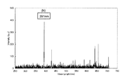
上記のパラメータ調整/部材選択を行った後のヘリウムプラズマが発する光のうち、波長範囲が250〜700nmの発光スペクトルを測定する(ステップS20)。ユーザはその測定結果を確認し、波長が640nmの輝線強度が他の波長の各輝線強度よりも大きい(すなわち最大)かどうか判断する(ステップS30)。最大ではないと判断する場合は、再度、パラメータ調整/部材選択を行う(ステップS10)。その際、ステップS10においては、発光スペクトルの測定結果を考慮した調整を行う。例えば、発光スペクトルにおいて、水素原子の輝線(波長が656nm)や酸素原子の輝線(波長が533nm及び544nm)が強く現れている場合は、誘電体部材をより水酸基(OH)含有量の少ないものとし(ステップS13)、水素原子や酸素原子以外の波長の輝線が強く現れている場合は、導入するヘリウムガスの純度を高めるよう調整する(ステップS11)。例えば図8に示すスペクトルデータは、検出器にヘリウムガス配管を接続した直後に測定した場合である。窒素の輝線(波長391nm)が強く現れており、配管内壁や接続部に混入した大気の置換がまだ十分ではないか、接続部にわずかなリークがあることを示している。時間をおいて十分な置換を行うか、リーク箇所を特定し、対処を行う必要がある。また、ヘリウム分子イオン(He2 +)の輝線(波長が640nm)強度が絶対的に小さいのであれば、導入するヘリウムガスの流量を増やすよう調整したり(ステップS12)、誘電体バリア放電における電圧の振幅及び/又は周波数を上げるよう調整する(ステップS14)。
そうして再び発光スペクトルを測定する(S20)。このような作業を繰り返し、波長が640nmの輝線強度が他の波長の各輝線強度よりも大きくなった時点で調整を終了する。Of the light emitted by the helium plasma after the above parameter adjustment / member selection, an emission spectrum having a wavelength range of 250 to 700 nm is measured (step S20). The user confirms the measurement result, and determines whether or not the emission line intensity at the wavelength of 640 nm is larger (that is, maximum) than the emission line intensity at other wavelengths (step S30). If it is determined that it is not the maximum, parameter adjustment / member selection is performed again (step S10). At this time, in step S10, adjustment is performed in consideration of the measurement result of the emission spectrum. For example, if the emission spectrum of hydrogen atoms (wavelength is 656 nm) or the emission lines of oxygen atoms (wavelengths are 533 nm and 544 nm) appears strongly in the emission spectrum, the dielectric member should have a lower hydroxyl (OH) content. (Step S13) If a bright line having a wavelength other than hydrogen atoms or oxygen atoms appears strongly, adjustment is made to increase the purity of the introduced helium gas (step S11). For example, the spectral data shown in FIG. 8 is measured when the helium gas pipe is connected to the detector. The emission line of nitrogen (wavelength 391nm) appears strongly, indicating that there is still not enough substitution of the atmosphere mixed in the pipe inner wall and connection part, or that there is a slight leak in the connection part. It is necessary to perform sufficient replacement after a certain amount of time, or to identify the leak location and take action. Further, if the bright line (wavelength 640 nm) intensity helium molecular ions (the He 2 +) that absolutely small, or adjusted to increase the flow rate of helium gas introduced (step S12), the voltage in the dielectric-barrier discharge Is adjusted to increase the amplitude and / or frequency (step S14).
Then, the emission spectrum is measured again (S20). Such an operation is repeated, and the adjustment is completed when the intensity of the emission line having a wavelength of 640 nm becomes larger than the intensity of each emission line of other wavelengths.
このようにして、ヘリウムプラズマが発する250〜700nmの波長範囲の光の中で640nmの光の強度が最大となるように放電イオン化電流検出器を調整する。 In this way, the discharge ionization current detector is adjusted so that the intensity of light at 640 nm is maximized in the light in the wavelength range of 250 to 700 nm emitted by helium plasma.
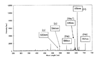
上記調整方法により放電イオン化電流検出器の調整を行ったところ、例えば、以下の条件において、ヘリウムプラズマが発する250〜700nmの波長範囲の光の中で640nmの光の強度が最大となることを確認した。まず、ヘリウム精製器23は、不純物濃度が10bbp以下のヘリウムガスを精製するヘリウム精製器とする。次に、バルブ22の開度を変えて導入するヘリウムガスの流量を、プラズマ生成部20内部のヘリウムガスを0.05〜2sec程度で置換できる程度の大きさとする。ヘリウムプラズマの密度は流量値に応じた大きさとなる。さらに、円筒管24は、水酸基(OH)含有量が10ppm以下の合成石英ガラスで形成する。最後に、放電用電極25に、振幅1〜10kV、周波数1〜50kHzの交流電圧を印加するよう、コントローラ27により交流電源26を制御する。なお、円筒管24は、サファイヤガラスや高純度酸化アルミニウムからなる誘電体部材を用いて形成してもよい。
When the discharge ionization current detector was adjusted by the above adjustment method, for example, it was confirmed that the light intensity at 640 nm was the maximum among the light in the wavelength range of 250 to 700 nm emitted by helium plasma under the following conditions: did. First, the
図2は、上記の条件で生成したヘリウムプラズマの発光スペクトルを示す。横軸は波長(nm)を、縦軸はスペクトル強度(任意単位)を表している。この発光スペクトルには、ヘリウム原子の輝線(波長が588nm及び707nm)及びヘリウム分子イオン(He2 +)の輝線(波長が640nm)の他、不純物である水素原子の輝線(波長が656nm)が現れている。また、波長が640nmの輝線強度は、他の波長の各輝線強度よりも大きく、支配的となっている。このことは、ヘリウム原子の3体衝突によるヘリウム分子イオン(He2 +)の生成が安定的に行われていることを示しており、このようなヘリウムプラズマは、不純物濃度が低く、光量が大きくかつ安定した真空紫外光を発するヘリウムプラズマであることがわかる。FIG. 2 shows an emission spectrum of helium plasma generated under the above conditions. The horizontal axis represents wavelength (nm) and the vertical axis represents spectral intensity (arbitrary unit). In this emission spectrum, emission lines of helium atoms (wavelengths of 588 nm and 707 nm) and emission lines of helium molecular ions (He 2 + ) (wavelength of 640 nm), as well as emission lines of hydrogen atoms as impurities (wavelength of 656 nm) appear. ing. In addition, the emission line intensity at a wavelength of 640 nm is larger and dominant than the emission line intensities at other wavelengths. This indicates that helium molecular ions (He 2 + ) are generated stably by three-body collision of helium atoms. Such helium plasma has a low impurity concentration and a large amount of light. It can also be seen that helium plasma emits stable vacuum ultraviolet light.
一方、図3は、円筒管24を、水酸基含有量が200ppm以上の溶融石英ガラスで形成し、それ以外の条件は上記と同じとした場合のヘリウムプラズマの発光スペクトルを示す。この発光スペクトルにも、ヘリウム原子の輝線(波長が588nm及び707nm)及びヘリウム分子イオン(He2 +)の輝線(波長が640nm)の他、不純物である水素原子の輝線(波長が656nm)が現れているが、さらに、図2の発光スペクトルにはなかった、酸素原子の輝線(波長が533nm及び544nm)も現れている。加えて、波長が656nmの輝線強度が大きくなり、波長が640nmの輝線強度よりも支配的となっている。これは、石英ガラスがヘリウムプラズマに晒されることで、そこに含まれていた水酸基(OH)が、プラズマにより酸素(O)や水素(H)に分解して放出されたことを示している。このようなヘリウムプラズマは、不純物濃度が高く、該ヘリウムプラズマが発する真空紫外光は、光量が小さくかつ不安定となる。On the other hand, FIG. 3 shows an emission spectrum of helium plasma when the
以上のとおり、上述の条件のもと放電イオン化電流検出器において生成されるヘリウムプラズマは、不純物濃度が低く、その結果、光量が大きくかつ安定した真空紫外光を発するため、放電イオン化電流検出器における測定の精度及び再現性が向上する。
また、予め、実験等によりそのような条件を定めておけば、以後、スペクトルアナライザ42を用いなくとも(すなわち図1に記載した構成であっても)、同様の性能を有する放電イオン化電流検出器を得ることが可能となる。すなわち、ヘリウムガスの純度及び流量を所定量に設定した上で、実験結果に基づいて、640nmの輝線強度が最大となる振幅及び/又は周波数の低周波電圧を供給するとよい。同様に、低周波電圧の振幅及び周波数を所定値に設定した上で、実験結果に基づいて、640nmの輝線強度が最大となるヘリウムガスの純度及び/又は流量を設定するとよい。As described above, the helium plasma generated in the discharge ionization current detector under the above-described conditions has a low impurity concentration and, as a result, emits a large amount of light and stable vacuum ultraviolet light. Measurement accuracy and reproducibility are improved.
Further, if such conditions are determined in advance by experiments or the like, the discharge ionization current detector having the same performance can be used without using the spectrum analyzer 42 (that is, even the configuration shown in FIG. 1). Can be obtained. That is, after setting the purity and flow rate of helium gas to predetermined amounts, a low-frequency voltage having an amplitude and / or frequency that maximizes the emission line intensity at 640 nm may be supplied based on the experimental results. Similarly, after setting the amplitude and frequency of the low frequency voltage to predetermined values, the purity and / or flow rate of the helium gas that maximizes the emission line intensity at 640 nm may be set based on the experimental results.
図4に示す構成の放電イオン化電流検出器を用いることには、以下のような利点もある。一般に、放電イオン化電流検出器を長期間使用すると、各部品の経時劣化等に伴い、検出器において生成されるヘリウムプラズマも異なったものとなる。その結果、250〜700nmの波長範囲において波長が640nmの輝線強度が他の波長の各輝線強度よりも大きくなるという発光スペクトルを有するヘリウムプラズマを生成できなくなるおそれがある。 The use of the discharge ionization current detector having the configuration shown in FIG. 4 has the following advantages. In general, when a discharge ionization current detector is used for a long period of time, the helium plasma generated in the detector also differs with the aging of each component. As a result, helium plasma having an emission spectrum in which the emission line intensity at a wavelength of 640 nm is larger than the emission line intensity at other wavelengths in the wavelength range of 250 to 700 nm may not be generated.
しかし、図4に示す構成であれば、使用者は、ヘリウムプラズマの真空紫外光における発光状態を把握したうえで試料成分の分析を行うことができるようになる。ここで、例えばあらかじめ発光状態の良否を判断するための判断基準を設けておけば、その判断基準とスペクトラムアナライザの測定結果とを照らし合わせることで的確な判断が可能となる。判断基準は、波長が640nmの輝線強度と他の各輝線強度との比較であってもよく、640nmの輝線強度の大きさのみであってもよい。また、例えば波長が640nmの輝線強度が、波長が656nmである水素原子の輝線強度より(例えば3倍程度)大きいといった判断基準でもよい。使用者はこのような判断基準に基づいて、発光状態が良いと判断した場合は試料成分の分析を行い、真空紫外光の発光状態が悪いと判断した場合は試料成分の分析を中止し、上述の調整を行うといったことが可能となる。
ここで、250〜700nm(紫外線から可視光)の波長範囲に対応した発光スペクトルアナライザは、真空紫外光を直接観測するための大型で高価な真空紫外分光装置等よりも安価であるため、検出器の製造コストの観点からも望ましいものとなる。However, with the configuration shown in FIG. 4, the user can analyze the sample components after grasping the light emission state of helium plasma in vacuum ultraviolet light. Here, for example, if a determination criterion for determining whether the light emission state is good or not is provided in advance, an accurate determination can be made by comparing the determination criterion with the measurement result of the spectrum analyzer. The determination criterion may be a comparison between the emission line intensity with a wavelength of 640 nm and each of the other emission line intensities, or only the magnitude of the emission line intensity of 640 nm. Further, for example, it may be a criterion that the emission line intensity at a wavelength of 640 nm is larger (for example, about 3 times) than the emission line intensity of a hydrogen atom having a wavelength of 656 nm. Based on these criteria, the user analyzes the sample component when it is determined that the light emission state is good, and stops the analysis of the sample component when it is determined that the light emission state of vacuum ultraviolet light is bad. It is possible to make adjustments.
Here, the emission spectrum analyzer corresponding to the wavelength range of 250 to 700 nm (ultraviolet to visible light) is less expensive than a large and expensive vacuum ultraviolet spectrometer for directly observing vacuum ultraviolet light. This is also desirable from the viewpoint of manufacturing cost.
図4の他に、ヘリウムプラズマの発光状態を確認する装置としては、図5に示す構成もある。この構成では、ヘリウムプラズマが発した光を、波長フィルタ51を通過させた後、フォトダイオード52に入射させる。フォトダイオード52は、入射した光の強度に応じた量の電荷を生する。これにより電流が流れるので、この電流をアンプ53で増幅し、電流/電圧変換器54で電圧として測定する。波長フィルタ51は、640mの波長の輝線を通過させるようにしておく。このような構成であっても、波長が640nmの輝線強度を測定してヘリウムプラズマの発光状態を確認することができる。また、上述の発光スペクトルアナライザを用いた場合よりも、検出器の製造コストが下がる。
In addition to FIG. 4, there is also a configuration shown in FIG. 5 as an apparatus for confirming the light emission state of helium plasma. In this configuration, light emitted from helium plasma is allowed to enter the
さらに、ヘリウムプラズマの発光状態から、低周波誘電体バリア放電における電圧及び周波数を自動的に制御するようにした構成を図6に示す。ここでは、電流/電圧変換器61とコントローラ62を、制御ライン63で接続し、通信できるようにした。コントローラ62は、電流/電圧変換器61の測定結果に基づいて交流電源26の電圧の振幅及び/又は周波数を制御する。ここでの制御は、ヘリウムプラズマが発する、波長が640nmの輝線強度が、他の波長の輝線強度よりも大きく、一定とする制御である。このような制御により、波長が640nmの輝線強度を一定とすれば、ヘリウムプラズマの真空紫外光の発光状態をより安定させることができ、検出器の測定の精度及び再現性をさらに向上させることができる。
電圧の振幅及び/又は周波数を制御する際には、ヘリウムプラズマのプラズマ温度が高くなりすぎないように注意する必要がある。温度が上がりすぎると、円筒管24を形成する誘電体部材の表面から放出される不純物も増加してしまうためである。このような点を考慮すると、振幅は1〜10kV、周波数は1〜50kHzの範囲とすることが好ましい。
なお、コントローラ62は、電流/電圧変換器61の測定結果に基づいて、ヘリウム精製器23を制御し、ヘリウムガスの純度を調整することで、ヘリウムプラズマが発する、波長が640nmの輝線強度が、他の波長の輝線強度よりも大きく、一定となるようにしてもよい。同様に、コントローラ62は、電流/電圧変換器61の測定結果に基づいて、バルブ22を制御し、ヘリウムガスの流量を調整することで、ヘリウムプラズマが発する、波長が640nmの輝線強度が、他の波長の輝線強度よりも大きく、一定となるようにしてもよい。
Furthermore, FIG. 6 shows a configuration in which the voltage and frequency in the low-frequency dielectric barrier discharge are automatically controlled from the light emission state of helium plasma. Here, the current /
Care should be taken when controlling the voltage amplitude and / or frequency so that the plasma temperature of the helium plasma does not become too high. This is because if the temperature rises too much, impurities released from the surface of the dielectric member forming the
The
10…放電イオン化電流検出器
20…プラズマ生成部
21…ガス導入口
22…バルブ
23…ヘリウム精製器
24…円筒管
25…放電用電極
26…交流電源
27、62…コントローラ
28、37…排出口
29…接地電極
30…イオン収集部
31…イオン収集用電極
32…バイアス用電極
33…絶縁部材
34…キャピラリ
35…直流電源
36…アンプ
41…光ファイバ
42…スペクトラムアナライザ
51…波長フィルタ
52…フォトダイオード
53…アンプ
54、61…電流/電圧変換器
63…制御ラインDESCRIPTION OF
Claims (7)
該ヘリウムプラズマが発する250〜700nmの波長範囲の光の波長毎の強度を検出する工程と、
前記波長範囲中で640nmの光の強度が最大となるように、導入するヘリウムガスの純度、導入するヘリウムガスの流量、低周波誘電体バリア放電における電圧の振幅、及び、低周波誘電体バリア放電における電圧の周波数の少なくとも1つを調整する工程と、
を備える放電イオン化電流検出器の調整方法。 In discharge ionization current detector using helium plasma generated by low frequency dielectric barrier discharge ,
Detecting the intensity for each wavelength of light in the wavelength range of 250 to 700 nm emitted by the helium plasma ;
The purity of the helium gas to be introduced, the flow rate of the helium gas to be introduced, the amplitude of the voltage in the low frequency dielectric barrier discharge, and the low frequency dielectric barrier discharge so that the intensity of light at 640 nm is maximized in the wavelength range. and adjusting at least one of the frequency of the voltage at,
A method for adjusting a discharge ionization current detector.
a)ヘリウムガスを導入するヘリウムガス導入部と、
b)低周波誘電体バリア放電に用いる放電用電極に印加する低周波電圧の振幅あるいは周波数を調整する電圧調整部と、
c)ヘリウムプラズマが発する250〜700nmの波長範囲の光の波長毎の強度を検出する光検出部と、
d)前記波長範囲中、640nmの光の強度が最大となるように、前記電圧調整部を制御する制御部と
を備える、放電イオン化電流検出器。 A discharge ionization current detector using helium plasma generated by a low frequency dielectric barrier discharge.
a) a helium gas introduction part for introducing helium gas;
b) a voltage adjusting unit for adjusting the amplitude or frequency of the low frequency voltage applied to the discharge electrode used for the low frequency dielectric barrier discharge;
c) a light detection unit for detecting the intensity for each wavelength of light in the wavelength range of 250 to 700 nm emitted by helium plasma;
d) A discharge ionization current detector comprising: a control unit that controls the voltage adjustment unit so that the intensity of light at 640 nm is maximized in the wavelength range.
a)ヘリウムガスを導入するヘリウムガス導入部と、
b)導入するヘリウムガスの純度を調整するヘリウムガス純度調整部と、
c)導入するヘリウムガスの流量を調整するヘリウムガス流量調整部と、
d)ヘリウムプラズマが発する250〜700nmの波長範囲の光の波長毎の強度を検出する光検出部と、
e)前記波長範囲中、640nmの光の強度が最大となるように、前記ヘリウムガス純度調整部、及び、前記ヘリウムガス流量調整部の少なくとも一つを制御する制御部と
を備える、放電イオン化電流検出器。 A discharge ionization current detector using helium plasma generated by a low frequency dielectric barrier discharge.
a) a helium gas introduction part for introducing helium gas;
b ) a helium gas purity adjusting unit for adjusting the purity of the helium gas to be introduced;
c ) a helium gas flow rate adjusting unit for adjusting the flow rate of the helium gas to be introduced ;
d) a light detection unit for detecting the intensity for each wavelength of light in the wavelength range of 250 to 700 nm emitted by helium plasma;
e) a control unit that controls at least one of the helium gas purity adjustment unit and the helium gas flow rate adjustment unit so that the intensity of light at 640 nm is maximized in the wavelength range;
A discharge ionization current detector.
所定値の純度および所定値の流量のヘリウムガスを導入するヘリウムガス導入部と、 A helium gas introduction section for introducing helium gas having a predetermined purity and a predetermined flow rate;
ヘリウムガスの純度および流量の各々が前記所定値に設定された場合に、ヘリウムプラズマが発する250〜700nmの波長範囲の光の中で、640nmの光の強度が最大となるような、低周波電圧の振幅及び周波数の各値が、実験によって予め求められており、前記振幅および前記周波数を、当該実験によって求められた各値に設定する設定部と、 A low frequency voltage that maximizes the intensity of light at 640 nm among the light in the wavelength range of 250 to 700 nm emitted by helium plasma when the purity and flow rate of helium gas are set to the predetermined values. Each value of the amplitude and the frequency is determined in advance by an experiment, and the setting unit sets the amplitude and the frequency to each value determined by the experiment,
前記設定部によって設定された低周波電圧を、低周波バリア放電に用いる放電用電極に印加する低周波電圧印加部と A low frequency voltage application unit configured to apply the low frequency voltage set by the setting unit to a discharge electrode used for low frequency barrier discharge;
を備える、放電イオン化電流検出器。 A discharge ionization current detector.
所定値の振幅および所定値の周波数の低周波電圧を、低周波バリア放電に用いる放電用電極に印加する低周波電圧印加部と、 A low-frequency voltage application unit that applies a low-frequency voltage having a predetermined amplitude and a predetermined frequency to a discharge electrode used for low-frequency barrier discharge;
低周波電圧の振幅および周波数の各々が前記所定値に設定された場合に、ヘリウムプラズマが発する250〜700nmの波長範囲の光の中で、640nmの光の強度が最大となるような、ヘリウムガスの純度および流量の各値が、実験によって予め求められており、前記純度および前記流量を、当該実験によって求められた各値に設定する設定部と、 Helium gas that maximizes the intensity of light at 640 nm in the 250 to 700 nm wavelength range emitted by helium plasma when each of the amplitude and frequency of the low frequency voltage is set to the predetermined value. Each value of the purity and the flow rate is determined in advance by an experiment, and the setting unit sets the purity and the flow rate to each value determined by the experiment,
前記設定部によって設定された純度および流量のヘリウムガスを導入するヘリウムガス導入部と A helium gas introduction section for introducing helium gas having the purity and flow rate set by the setting section;
を備える、放電イオン化電流検出器。 A discharge ionization current detector.
Applications Claiming Priority (1)
| Application Number | Priority Date | Filing Date | Title |
|---|---|---|---|
| PCT/JP2013/053659 WO2014125610A1 (en) | 2013-02-15 | 2013-02-15 | Discharge ionization current detector and method for adjusting same |
Publications (2)
| Publication Number | Publication Date |
|---|---|
| JP5987968B2 true JP5987968B2 (en) | 2016-09-07 |
| JPWO2014125610A1 JPWO2014125610A1 (en) | 2017-02-02 |
Family
ID=51353640
Family Applications (1)
| Application Number | Title | Priority Date | Filing Date |
|---|---|---|---|
| JP2015500053A Expired - Fee Related JP5987968B2 (en) | 2013-02-15 | 2013-02-15 | Discharge ionization current detector and adjustment method thereof |
Country Status (4)
| Country | Link |
|---|---|
| US (1) | US9784714B2 (en) |
| JP (1) | JP5987968B2 (en) |
| CN (1) | CN105074449B (en) |
| WO (1) | WO2014125610A1 (en) |
Families Citing this family (9)
| Publication number | Priority date | Publication date | Assignee | Title |
|---|---|---|---|---|
| CN104316617A (en) * | 2014-11-06 | 2015-01-28 | 上海华爱色谱分析技术有限公司 | Gas chromatograph for analysis on trace light dydrocarbon impurity in electronic-grade propylene |
| EP3693733B1 (en) * | 2015-03-06 | 2022-09-07 | Mécanique Analytique Inc. | Discharge-based photo ionisation detector for use with a gas chromatography system |
| CN106324076B (en) * | 2016-08-22 | 2020-01-21 | 中国科学院电子学研究所 | Helium ionization detector with three-electrode structure |
| JP6775141B2 (en) | 2016-09-08 | 2020-10-28 | 株式会社島津製作所 | Dielectric barrier discharge ionization detector |
| JP6747197B2 (en) * | 2016-09-08 | 2020-08-26 | 株式会社島津製作所 | Dielectric barrier discharge ionization detector |
| JP6743599B2 (en) | 2016-09-08 | 2020-08-19 | 株式会社島津製作所 | Dielectric barrier discharge ionization detector |
| JP6675709B2 (en) * | 2016-09-08 | 2020-04-01 | 株式会社島津製作所 | Dielectric barrier discharge ionization detector |
| JP6747198B2 (en) | 2016-09-08 | 2020-08-26 | 株式会社島津製作所 | Dielectric barrier discharge ionization detector |
| CN111624272A (en) * | 2020-06-16 | 2020-09-04 | 中国农业科学院农业质量标准与检测技术研究所 | Device and method for improving analysis sensitivity of liquid chromatography atomic spectrometry |
Citations (4)
| Publication number | Priority date | Publication date | Assignee | Title |
|---|---|---|---|---|
| WO2009119050A1 (en) * | 2008-03-25 | 2009-10-01 | 国立大学法人大阪大学 | Electric discharge ionization current detector |
| JP2011038961A (en) * | 2009-08-17 | 2011-02-24 | Electric Power Dev Co Ltd | Plasma emission analysis method and apparatus therefor |
| JP2011117854A (en) * | 2009-12-04 | 2011-06-16 | Osaka Univ | Discharge ionization current detector |
| WO2012169419A1 (en) * | 2011-06-07 | 2012-12-13 | 株式会社島津製作所 | Discharge ionization current detector |
Family Cites Families (12)
| Publication number | Priority date | Publication date | Assignee | Title |
|---|---|---|---|---|
| US20060208186A1 (en) | 2005-03-15 | 2006-09-21 | Goodley Paul C | Nanospray ion source with multiple spray emitters |
| JP4679389B2 (en) | 2006-02-20 | 2011-04-27 | 株式会社日立ハイテクノロジーズ | Detector and analyzer for detecting a sample with low ionization energy |
| JP2007315853A (en) | 2006-05-24 | 2007-12-06 | Chugoku Electric Power Co Inc:The | Strain gauge |
| JP2008004673A (en) | 2006-06-21 | 2008-01-10 | Tokyo Seimitsu Co Ltd | Chuck for prober |
| US7520160B1 (en) | 2007-10-04 | 2009-04-21 | Schlumberger Technology Corporation | Electrochemical sensor |
| JP5136300B2 (en) * | 2008-09-02 | 2013-02-06 | 株式会社島津製作所 | Discharge ionization current detector |
| JP5423439B2 (en) | 2010-02-01 | 2014-02-19 | 株式会社島津製作所 | Discharge ionization current detector |
| JP5470543B2 (en) * | 2010-04-26 | 2014-04-16 | 株式会社島津製作所 | Discharge ionization current detector |
| JP5470544B2 (en) | 2010-06-28 | 2014-04-16 | 株式会社島津製作所 | Discharge ionization current detector |
| JP5445353B2 (en) * | 2010-06-28 | 2014-03-19 | 株式会社島津製作所 | Discharge ionization current detector |
| JP5614379B2 (en) | 2011-06-21 | 2014-10-29 | 株式会社島津製作所 | Discharge ionization current detector and gas chromatograph apparatus |
| CN102519938B (en) * | 2011-12-13 | 2014-06-25 | 清华大学 | Atomic vapor generation method and device based on dielectric barrier discharge |
-
2013
- 2013-02-15 JP JP2015500053A patent/JP5987968B2/en not_active Expired - Fee Related
- 2013-02-15 US US14/766,914 patent/US9784714B2/en active Active
- 2013-02-15 CN CN201380073123.1A patent/CN105074449B/en not_active Expired - Fee Related
- 2013-02-15 WO PCT/JP2013/053659 patent/WO2014125610A1/en active Application Filing
Patent Citations (4)
| Publication number | Priority date | Publication date | Assignee | Title |
|---|---|---|---|---|
| WO2009119050A1 (en) * | 2008-03-25 | 2009-10-01 | 国立大学法人大阪大学 | Electric discharge ionization current detector |
| JP2011038961A (en) * | 2009-08-17 | 2011-02-24 | Electric Power Dev Co Ltd | Plasma emission analysis method and apparatus therefor |
| JP2011117854A (en) * | 2009-12-04 | 2011-06-16 | Osaka Univ | Discharge ionization current detector |
| WO2012169419A1 (en) * | 2011-06-07 | 2012-12-13 | 株式会社島津製作所 | Discharge ionization current detector |
Non-Patent Citations (1)
| Title |
|---|
| JPN6013011924; GRAS R et al: 'Gas Chromatographic Applications with the Dielectric Barrier Discharge Detector' Journal of Chromatographic Science Vol.44, No.2, 200602, Page.101-107,3A-4A * |
Also Published As
| Publication number | Publication date |
|---|---|
| JPWO2014125610A1 (en) | 2017-02-02 |
| US20150369777A1 (en) | 2015-12-24 |
| CN105074449A (en) | 2015-11-18 |
| US9784714B2 (en) | 2017-10-10 |
| WO2014125610A1 (en) | 2014-08-21 |
| CN105074449B (en) | 2017-08-08 |
Similar Documents
| Publication | Publication Date | Title |
|---|---|---|
| JP5987968B2 (en) | Discharge ionization current detector and adjustment method thereof | |
| JP5136300B2 (en) | Discharge ionization current detector | |
| JP4936492B2 (en) | Discharge ionization current detector | |
| US6333632B1 (en) | Alternating current discharge ionization detector | |
| JP5445353B2 (en) | Discharge ionization current detector | |
| Olenici-Craciunescu et al. | Characterization of a capillary dielectric barrier plasma jet for use as a soft ionization source by optical emission and ion mobility spectrometry | |
| JP5861739B2 (en) | Discharge ionization current detector | |
| US8829913B2 (en) | Discharge ionization current detector | |
| JP5645771B2 (en) | Mass spectrometer | |
| JP2018513965A (en) | Multi-mode plasma optical emission gas detector | |
| US8920610B2 (en) | Method and apparatus for detecting ionisable gases in particular organic molecules, preferably hydrocarbons | |
| EP2920583B1 (en) | Photoionization detector for gas chromatography having two separately ionizing sources | |
| Stefanović et al. | Argon metastable dynamics and lifetimes in a direct current microdischarge | |
| Hoskinson et al. | Low-power microwave-generated helium microplasma for molecular and atomic spectrometry | |
| JP5773061B2 (en) | Discharge ionization current detector and its aging treatment method | |
| JP5614379B2 (en) | Discharge ionization current detector and gas chromatograph apparatus | |
| JP7318608B2 (en) | discharge ionization detector | |
| US20220099636A1 (en) | Dielectric Barrier Discharge Ionization Detector and Gas Chromatography Analyzer | |
| Fukuhara et al. | Characterization of a microhollow cathode discharge plasma in helium or air with water vapor | |
| JP2011053078A (en) | Method and device for detection using plasma | |
| Hadidi et al. | Spectroscopic measurements of a 5-30 kHz, high voltage atmospheric pressure discharge | |
| Senkan et al. | CA 90095-1592, Fax: 310-267-0177, e. mail: senkan@ seas. ucla. edu* To whom correspondence should be sent. |
Legal Events
| Date | Code | Title | Description |
|---|---|---|---|
| TRDD | Decision of grant or rejection written | ||
| A01 | Written decision to grant a patent or to grant a registration (utility model) |
Free format text: JAPANESE INTERMEDIATE CODE: A01 Effective date: 20160712 |
|
| A61 | First payment of annual fees (during grant procedure) |
Free format text: JAPANESE INTERMEDIATE CODE: A61 Effective date: 20160725 |
|
| R151 | Written notification of patent or utility model registration |
Ref document number: 5987968 Country of ref document: JP Free format text: JAPANESE INTERMEDIATE CODE: R151 |
|
| LAPS | Cancellation because of no payment of annual fees |