JP6610068B2 - Liquid supply unit - Google Patents
Liquid supply unit Download PDFInfo
- Publication number
- JP6610068B2 JP6610068B2 JP2015155742A JP2015155742A JP6610068B2 JP 6610068 B2 JP6610068 B2 JP 6610068B2 JP 2015155742 A JP2015155742 A JP 2015155742A JP 2015155742 A JP2015155742 A JP 2015155742A JP 6610068 B2 JP6610068 B2 JP 6610068B2
- Authority
- JP
- Japan
- Prior art keywords
- liquid
- supply unit
- storage chamber
- liquid supply
- wall
- Prior art date
- Legal status (The legal status is an assumption and is not a legal conclusion. Google has not performed a legal analysis and makes no representation as to the accuracy of the status listed.)
- Expired - Fee Related
Links
- 239000007788 liquid Substances 0.000 title claims description 1043
- 238000003860 storage Methods 0.000 claims description 298
- 238000004891 communication Methods 0.000 claims description 148
- 238000005192 partition Methods 0.000 claims description 78
- 230000007246 mechanism Effects 0.000 claims description 49
- 238000002347 injection Methods 0.000 claims description 27
- 239000007924 injection Substances 0.000 claims description 27
- 239000000976 ink Substances 0.000 description 105
- 238000010586 diagram Methods 0.000 description 14
- 230000004048 modification Effects 0.000 description 13
- 238000012986 modification Methods 0.000 description 13
- 238000004132 cross linking Methods 0.000 description 7
- 238000000034 method Methods 0.000 description 7
- 239000012528 membrane Substances 0.000 description 6
- 238000013459 approach Methods 0.000 description 5
- 238000004519 manufacturing process Methods 0.000 description 5
- 239000000463 material Substances 0.000 description 5
- 230000002093 peripheral effect Effects 0.000 description 5
- 238000011144 upstream manufacturing Methods 0.000 description 5
- 239000000835 fiber Substances 0.000 description 4
- 229920005989 resin Polymers 0.000 description 4
- 239000011347 resin Substances 0.000 description 4
- 239000000758 substrate Substances 0.000 description 4
- -1 polyethylene Polymers 0.000 description 3
- 239000000126 substance Substances 0.000 description 3
- 239000004743 Polypropylene Substances 0.000 description 2
- 238000013461 design Methods 0.000 description 2
- 238000005401 electroluminescence Methods 0.000 description 2
- 239000006260 foam Substances 0.000 description 2
- 230000006872 improvement Effects 0.000 description 2
- 239000004973 liquid crystal related substance Substances 0.000 description 2
- 239000002184 metal Substances 0.000 description 2
- 229910052751 metal Inorganic materials 0.000 description 2
- 239000003921 oil Substances 0.000 description 2
- 230000003287 optical effect Effects 0.000 description 2
- 239000002245 particle Substances 0.000 description 2
- 229920001155 polypropylene Polymers 0.000 description 2
- 229920002635 polyurethane Polymers 0.000 description 2
- 239000004814 polyurethane Substances 0.000 description 2
- 230000009467 reduction Effects 0.000 description 2
- 239000000243 solution Substances 0.000 description 2
- XLYOFNOQVPJJNP-UHFFFAOYSA-N water Substances O XLYOFNOQVPJJNP-UHFFFAOYSA-N 0.000 description 2
- 238000000018 DNA microarray Methods 0.000 description 1
- 239000004698 Polyethylene Substances 0.000 description 1
- 239000004793 Polystyrene Substances 0.000 description 1
- 230000004308 accommodation Effects 0.000 description 1
- 239000002253 acid Substances 0.000 description 1
- 230000008901 benefit Effects 0.000 description 1
- 230000015572 biosynthetic process Effects 0.000 description 1
- 230000000694 effects Effects 0.000 description 1
- 239000007772 electrode material Substances 0.000 description 1
- 238000005530 etching Methods 0.000 description 1
- 239000012530 fluid Substances 0.000 description 1
- 239000012943 hotmelt Substances 0.000 description 1
- 239000003049 inorganic solvent Substances 0.000 description 1
- 229910001867 inorganic solvent Inorganic materials 0.000 description 1
- 239000011344 liquid material Substances 0.000 description 1
- 239000007791 liquid phase Substances 0.000 description 1
- 229910001338 liquidmetal Inorganic materials 0.000 description 1
- 239000010687 lubricating oil Substances 0.000 description 1
- 238000005461 lubrication Methods 0.000 description 1
- 230000013011 mating Effects 0.000 description 1
- 239000000155 melt Substances 0.000 description 1
- 239000002923 metal particle Substances 0.000 description 1
- 239000000203 mixture Substances 0.000 description 1
- 238000000465 moulding Methods 0.000 description 1
- 239000011368 organic material Substances 0.000 description 1
- 239000003960 organic solvent Substances 0.000 description 1
- 239000000049 pigment Substances 0.000 description 1
- 229920000573 polyethylene Polymers 0.000 description 1
- 229920002223 polystyrene Polymers 0.000 description 1
- 230000002265 prevention Effects 0.000 description 1
- 230000008569 process Effects 0.000 description 1
- 238000012545 processing Methods 0.000 description 1
- 230000000630 rising effect Effects 0.000 description 1
- 239000007787 solid Substances 0.000 description 1
- 239000002904 solvent Substances 0.000 description 1
- 238000000638 solvent extraction Methods 0.000 description 1
- 229920003002 synthetic resin Polymers 0.000 description 1
- 239000000057 synthetic resin Substances 0.000 description 1
Images


Classifications
-
- B—PERFORMING OPERATIONS; TRANSPORTING
- B41—PRINTING; LINING MACHINES; TYPEWRITERS; STAMPS
- B41J—TYPEWRITERS; SELECTIVE PRINTING MECHANISMS, i.e. MECHANISMS PRINTING OTHERWISE THAN FROM A FORME; CORRECTION OF TYPOGRAPHICAL ERRORS
- B41J2/00—Typewriters or selective printing mechanisms characterised by the printing or marking process for which they are designed
- B41J2/005—Typewriters or selective printing mechanisms characterised by the printing or marking process for which they are designed characterised by bringing liquid or particles selectively into contact with a printing material
- B41J2/01—Ink jet
- B41J2/17—Ink jet characterised by ink handling
- B41J2/175—Ink supply systems ; Circuit parts therefor
- B41J2/17503—Ink cartridges
- B41J2/1752—Mounting within the printer
-
- B—PERFORMING OPERATIONS; TRANSPORTING
- B41—PRINTING; LINING MACHINES; TYPEWRITERS; STAMPS
- B41J—TYPEWRITERS; SELECTIVE PRINTING MECHANISMS, i.e. MECHANISMS PRINTING OTHERWISE THAN FROM A FORME; CORRECTION OF TYPOGRAPHICAL ERRORS
- B41J2/00—Typewriters or selective printing mechanisms characterised by the printing or marking process for which they are designed
- B41J2/005—Typewriters or selective printing mechanisms characterised by the printing or marking process for which they are designed characterised by bringing liquid or particles selectively into contact with a printing material
- B41J2/01—Ink jet
- B41J2/17—Ink jet characterised by ink handling
- B41J2/175—Ink supply systems ; Circuit parts therefor
- B41J2/17503—Ink cartridges
- B41J2/17513—Inner structure
-
- B—PERFORMING OPERATIONS; TRANSPORTING
- B41—PRINTING; LINING MACHINES; TYPEWRITERS; STAMPS
- B41J—TYPEWRITERS; SELECTIVE PRINTING MECHANISMS, i.e. MECHANISMS PRINTING OTHERWISE THAN FROM A FORME; CORRECTION OF TYPOGRAPHICAL ERRORS
- B41J2/00—Typewriters or selective printing mechanisms characterised by the printing or marking process for which they are designed
- B41J2/005—Typewriters or selective printing mechanisms characterised by the printing or marking process for which they are designed characterised by bringing liquid or particles selectively into contact with a printing material
- B41J2/01—Ink jet
- B41J2/17—Ink jet characterised by ink handling
- B41J2/175—Ink supply systems ; Circuit parts therefor
- B41J2/17503—Ink cartridges
- B41J2/17526—Electrical contacts to the cartridge
- B41J2/1753—Details of contacts on the cartridge, e.g. protection of contacts
-
- B—PERFORMING OPERATIONS; TRANSPORTING
- B41—PRINTING; LINING MACHINES; TYPEWRITERS; STAMPS
- B41J—TYPEWRITERS; SELECTIVE PRINTING MECHANISMS, i.e. MECHANISMS PRINTING OTHERWISE THAN FROM A FORME; CORRECTION OF TYPOGRAPHICAL ERRORS
- B41J2/00—Typewriters or selective printing mechanisms characterised by the printing or marking process for which they are designed
- B41J2/005—Typewriters or selective printing mechanisms characterised by the printing or marking process for which they are designed characterised by bringing liquid or particles selectively into contact with a printing material
- B41J2/01—Ink jet
- B41J2/17—Ink jet characterised by ink handling
- B41J2/175—Ink supply systems ; Circuit parts therefor
- B41J2/17503—Ink cartridges
- B41J2/17553—Outer structure
-
- B—PERFORMING OPERATIONS; TRANSPORTING
- B41—PRINTING; LINING MACHINES; TYPEWRITERS; STAMPS
- B41J—TYPEWRITERS; SELECTIVE PRINTING MECHANISMS, i.e. MECHANISMS PRINTING OTHERWISE THAN FROM A FORME; CORRECTION OF TYPOGRAPHICAL ERRORS
- B41J29/00—Details of, or accessories for, typewriters or selective printing mechanisms not otherwise provided for
- B41J29/02—Framework
-
- B—PERFORMING OPERATIONS; TRANSPORTING
- B41—PRINTING; LINING MACHINES; TYPEWRITERS; STAMPS
- B41J—TYPEWRITERS; SELECTIVE PRINTING MECHANISMS, i.e. MECHANISMS PRINTING OTHERWISE THAN FROM A FORME; CORRECTION OF TYPOGRAPHICAL ERRORS
- B41J29/00—Details of, or accessories for, typewriters or selective printing mechanisms not otherwise provided for
- B41J29/12—Guards, shields or dust excluders
- B41J29/13—Cases or covers
Landscapes
- Ink Jet (AREA)
Description
本発明は、液体噴射装置に液体を供給するための技術に関する。 The present invention relates to a technique for supplying a liquid to a liquid ejecting apparatus.
従来、プリンターにインクを供給する技術として、インクタンク装着部にインクタンクを装着し、インクタンク装着部が備えるヘッドユニットのインク受入管にインクタンクのインクを供給する技術が知られている(例えば、特許文献1)。 2. Description of the Related Art Conventionally, as a technique for supplying ink to a printer, a technique is known in which an ink tank is mounted on an ink tank mounting portion and ink in an ink tank is supplied to an ink receiving pipe of a head unit provided in the ink tank mounting portion (for example, Patent Document 1).
上記技術では、ブラックインクを収容するブラックインクタンクと、4色のカラーインクを収容するカラーインクタンクとがインクタンク装着部に装着される。インクタンク装着部は、ブラックインクタンクが装着される第1装着部と、カラーインクタンクが装着される第2装着部との間に配置された仕切り壁を有する。 In the above technique, a black ink tank that stores black ink and a color ink tank that stores four color inks are mounted on the ink tank mounting portion. The ink tank mounting portion has a partition wall disposed between a first mounting portion on which the black ink tank is mounted and a second mounting portion on which the color ink tank is mounted.
ここで、インクタンク装着部に装着されるインクタンク(例えば、ブラックインクタンク)のインク容量を増やしたいという要望がある。また、従来の技術において、低コスト化、省資源化、製造の容易化、使い勝手の向上等が望まれている。また、このような要望は、インクを収容するインクタンクに限らず、インク以外の他の種類の液体を液体噴射装置に供給するために、液体噴射装置に装着される液体供給ユニットについても共通する。 Here, there is a desire to increase the ink capacity of an ink tank (for example, a black ink tank) mounted on the ink tank mounting portion. Further, in the prior art, cost reduction, resource saving, ease of manufacturing, improvement in usability, etc. are desired. Such a demand is not limited to an ink tank that contains ink, but is common to a liquid supply unit that is mounted on a liquid ejecting apparatus in order to supply other types of liquid other than ink to the liquid ejecting apparatus. .
本発明は、上述の課題の少なくとも一部を解決するためになされたものであり、以下の形態又は適用例として実現することが可能である。 SUMMARY An advantage of some aspects of the invention is to solve at least a part of the problems described above, and the invention can be implemented as the following forms or application examples.
(1)本発明の一形態によれば、液体導入部を有する第1装着部と、第2装着部と、前記第1装着部と前記第2装着部とを隔て、スリットを有する隔壁と、を備える液体噴射装置に、装着可能な液体供給ユニットが提供される。この液体供給ユニットは、底壁部と、前記底壁部と対向する上壁部と、前記上壁部と前記底壁部とに交差する第1外壁部及び第2外壁部と、を備える。また、この液体供給ユニットは、前記第1外壁部によって区画形成される第1液体収容室を備える。前記第1液体収容室は、前記液体供給ユニットを前記液体噴射装置に装着した装着状態において、前記第1装着部に装着される。また、この液体供給ユニットは、前記第2外壁部によって区画形成される第2液体収容室を備える。前記第2液体収容室は、前記装着状態において、前記第2装着部に装着される。また、この液体供給ユニットは、前記底壁部に、前記第1液体収容室と連通するように設けられた液体供給部を備える。前記液体供給部は、前記装着状態において、前記液体導入部に接続され、前記液体導入部に液体を供給する。また、この液体供給ユニットは、前記第1液体収容室と前記第2液体収容室とを連通させる液体連通部を備える。前記第1液体収容室を区画形成する第1外壁部と前記第2液体収容室を区画形成する第2外壁部との間には、前記装着状態において、前記隔壁が挿入される隙間が形成されている。
上記形態によれば、液体供給ユニットが隙間を有することで、隔壁が装着の障害となることなく、液体供給ユニットを第1装着部と第2装着部とに亘って配置できる。これにより、第1装着部に装着可能な第1液体収容室に収容された液体を液体供給部から液体導入部に供給することに加え、液体連通部を介して、第2装着部に装着可能な第2液体収容室に収容された液体を第1液体収容室に流通させることができる。これにより、液体供給ユニットが収容できる液体の容量を増大できる。
(1) According to one aspect of the present invention, a first mounting part having a liquid introduction part, a second mounting part, a partition wall having a slit across the first mounting part and the second mounting part, A liquid supply unit that can be attached to a liquid ejecting apparatus is provided. The liquid supply unit includes a bottom wall portion, an upper wall portion facing the bottom wall portion, and a first outer wall portion and a second outer wall portion intersecting the upper wall portion and the bottom wall portion. The liquid supply unit includes a first liquid storage chamber that is defined by the first outer wall. The first liquid storage chamber is mounted on the first mounting portion when the liquid supply unit is mounted on the liquid ejecting apparatus. The liquid supply unit includes a second liquid storage chamber defined by the second outer wall. The second liquid storage chamber is mounted on the second mounting portion in the mounted state. In addition, the liquid supply unit includes a liquid supply portion provided on the bottom wall portion so as to communicate with the first liquid storage chamber. In the mounted state, the liquid supply unit is connected to the liquid introduction unit and supplies liquid to the liquid introduction unit. In addition, the liquid supply unit includes a liquid communication unit that communicates the first liquid storage chamber and the second liquid storage chamber. A gap into which the partition wall is inserted is formed between the first outer wall portion defining the first liquid storage chamber and the second outer wall portion defining the second liquid storage chamber in the mounted state. ing.
According to the said form, a liquid supply unit can be arrange | positioned over a 1st mounting part and a 2nd mounting part, without a partition becoming an obstruction | occlusion of mounting | wearing because a liquid supply unit has a clearance gap. As a result, in addition to supplying the liquid stored in the first liquid storage chamber that can be mounted to the first mounting section from the liquid supply section to the liquid introduction section, it can be mounted to the second mounting section via the liquid communication section. The liquid stored in the second liquid storage chamber can be distributed to the first liquid storage chamber. Thereby, the capacity | capacitance of the liquid which a liquid supply unit can accommodate can be increased.
(2)上記形態の液体供給ユニットであって、前記装着状態において、前記液体噴射装置の前記第1装着部に設けられた第1電極部と電気的に接続される第1端子部と、前記装着状態において、前記液体噴射装置の前記第2装着部に設けられた前記第2電極部と電気的に接続される第2端子部と、前記装着状態において、前記液体噴射装置の前記第1装着部に設けられた第1係合部に対して当接可能な第1被係合部と、前記装着状態において、前記液体噴射装置の前記第2装着部に設けられた第2係合部に対して当接可能な第2被係合部と、を備えていても良い。
上記形態によれば、第1及び第2係合部によって、第1及び第2端子部を、第1及び第2電極部に、しっかりと接続することができる。
(2) The liquid supply unit according to the above aspect, wherein in the mounted state, the first terminal unit electrically connected to the first electrode unit provided in the first mounting unit of the liquid ejecting apparatus; A second terminal portion electrically connected to the second electrode portion provided in the second mounting portion of the liquid ejecting apparatus in the mounted state; and the first mounting of the liquid ejecting apparatus in the mounted state. A first engaged portion that can abut against a first engaging portion provided in a portion, and a second engaging portion provided in the second mounting portion of the liquid ejecting apparatus in the mounted state. And a second engaged portion that can come into contact with the second engaging portion.
According to the said form, a 1st and 2nd terminal part can be firmly connected to a 1st and 2nd electrode part by a 1st and 2nd engaging part.
(3)上記形態の液体供給ユニットであって、前記液体連通部は第1液体流路を含み、前記液体供給ユニットを前記液体噴射装置に装着した装着状態において、前記液体供給ユニットを前記上壁部から前記底壁部に向かう鉛直下方向に向かって平面視したとき、前記第1液体流路は前記隔壁と重なっても良い。
上記形態によれば、第1液体流路を含む液体連通部によって、隔壁に妨げられることなく第2液体収容室の液体を第1液体収容室へと流通させることができる。
(3) The liquid supply unit according to the above aspect, wherein the liquid communication unit includes a first liquid flow path, and the liquid supply unit is mounted on the upper wall in a mounted state in which the liquid supply unit is mounted on the liquid ejecting apparatus. The first liquid channel may overlap the partition when viewed in a plan view from the bottom toward the bottom wall toward the bottom wall.
According to the said form, the liquid of a 2nd liquid storage chamber can be distribute | circulated to a 1st liquid storage chamber by the liquid communication part containing a 1st liquid flow path, without being interrupted by a partition.
上記形態の液体供給ユニットであって、前記液体連通部は第2液体流路を含み、前記装着状態において、前記液体供給ユニットを前記鉛直下方向に向かって平面視したとき、前記第2液体流路は前記第2装着部と重なっても良い。
上記形態によれば、第2液体流路を含む液体連通部によって、第2液体収容室の液体を第1液体収容室へと流通させることができる。
A liquid supply unit of the upper Symbol embodiment, the comprises a liquid communicating portion and the second liquid flow path, in the mounted state, when viewed in plan toward the liquid supply unit to the vertically downward direction, the second liquid The flow path may overlap the second mounting portion.
According to the said form, the liquid of a 2nd liquid storage chamber can be distribute | circulated to a 1st liquid storage chamber by the liquid communication part containing a 2nd liquid flow path.
上記形態の液体供給ユニットであって、前記液体連通部は第3液体流路を含み、前記装着状態において、前記液体供給ユニットを前記鉛直下方向に向かって平面視したとき、前記第3液体流路は前記第1装着部と重なっても良い。
上記形態によれば、第3液体流路を含む液体連通部によって、第2液体収容室の液体を第1液体収容室へと流通させることができる。
A liquid supply unit of the upper Symbol embodiment, the comprises a liquid communicating portion and the third liquid flow path, in the mounted state, when viewed in plan toward the liquid supply unit to the vertically downward direction, the third liquid The flow path may overlap the first mounting portion .
According to the said form, the liquid of a 2nd liquid storage chamber can be distribute | circulated to a 1st liquid storage chamber by the liquid communication part containing a 3rd liquid flow path.
上記形態の液体供給ユニットであって、前記第1液体流路は、前記底壁部よりも前記上壁部に近い位置に設けられていても良い。
上記形態によれば、第1液体流路を含む液体連通部によって、隔壁に妨げられることなく第2液体収容室の液体を第1液体収容室へと流通させることができる。
A liquid supply unit of the upper Symbol embodiment, the first liquid flow path, may be provided at a position closer to the upper wall portion than the bottom wall portion.
According to the said form, the liquid of a 2nd liquid storage chamber can be distribute | circulated to a 1st liquid storage chamber by the liquid communication part containing a 1st liquid flow path, without being interrupted by a partition.
(4)上記形態の液体供給ユニットであって、さらに、前記第1外壁部と前記第2外壁部とを連結する架橋部を有し、前記架橋部は、前記装着状態において前記隔壁の前記スリットに挿入されても良い。
上記形態によれば、架橋部によって、隙間を有する液体供給ユニットの強度を向上できる。
(4) The liquid supply unit according to the above aspect, further including a bridging portion that couples the first outer wall portion and the second outer wall portion , wherein the bridging portion is the slit of the partition wall in the mounted state. May be inserted .
According to the said form, the intensity | strength of the liquid supply unit which has a clearance gap can be improved with a bridge | crosslinking part .
上記形態の液体供給ユニットであって、前記液体連通部の少なくとも一部は、前記架橋部に設けられていても良い。
上記形態によれば、架橋部を有効に利用して第1液体収容室と第2液体収容室とを連通させることができる。
A liquid supply unit of the upper Symbol embodiment, at least a portion of said liquid communication portion may be provided on the bridge portion.
According to the said form, a 1st liquid storage chamber and a 2nd liquid storage chamber can be connected using a bridge | crosslinking part effectively.
上記形態の液体供給ユニットであって、前記液体連通部の少なくとも一部は、前記架橋部のうち前記上壁部よりも前記底壁部に近い位置に設けられていても良い。
上記形態によれば、第2液体収容室のうち上壁部よりも底壁部に近い部分に収容された液体を第1液体収容室に流通させることができる。
A liquid supply unit of the upper Symbol embodiment, at least a portion of said liquid communication portion may be provided at a position closer to the bottom wall portion than the upper wall portion of the bridge portion.
According to the said form , the liquid accommodated in the part close | similar to a bottom wall part rather than an upper wall part among 2nd liquid storage chambers can be distribute | circulated to a 1st liquid storage chamber.
(5)上記形態の液体供給ユニットであって、前記液体連通部の少なくとも一部はチューブによって構成されていても良い。
上記形態によれば、液体連通部の設計の自由度が向上できる。
(5) In the liquid supply unit according to the above aspect, at least a part of the liquid communication portion may be constituted by a tube.
According to the said form , the freedom degree of design of a liquid communication part can be improved.
(6)上記形態の液体供給ユニットであって、前記液体連通部の少なくとも一部は、前記第2壁部に形成されていても良い。
この形態によれば、第2壁部を利用して液体連通部の少なくとも一部を形成できる。
(6) In the liquid supply unit of the above aspect, at least a part of the liquid communication part may be formed on the second wall part.
According to this aspect, at least a part of the liquid communication portion can be formed using the second wall portion.
(7)上記形態の液体供給ユニットであって、さらに、前記第1液体収容室と前記第2液体収容室と前記液体連通部とに亘って配置された第1液体保持部材を有しても良い。
上記形態によれば、第1液体保持部材によって、第2液体収容室の液体を、液体連通部を介して第1液体収容室に円滑に移動させることができる。
(7) The liquid supply unit according to the above aspect may further include a first liquid holding member disposed across the first liquid storage chamber, the second liquid storage chamber, and the liquid communication portion. good.
According to the said form, the liquid of a 2nd liquid storage chamber can be smoothly moved to a 1st liquid storage chamber via a liquid communication part by a 1st liquid holding member.
上記形態の液体供給ユニットであって、さらに、前記第1液体収容室のうち、前記液体供給部と前記第1液体保持部材との間に配置された第2液体保持部材を有しても良い。
上記形態によれば、第2液体保持部材に液体を保持させることができる。
A liquid supply unit of the upper Symbol embodiment, further, one of the first liquid storage chamber, have a second liquid retaining member disposed between the liquid feed portion and the first liquid retaining member good.
According to the said form, a 2nd liquid holding member can hold | maintain a liquid.
(8)上記形態の液体供給ユニットであって、さらに、前記液体供給ユニットの外部の大気と前記第1液体収容室とを連通する大気連通路と、前記第1液体収容室に配置された液体保持部材と、を有しても良い。
この形態によれば、第1液体収容室の液体の消費に伴って第2液体収容室の液体を液体連通部を介して第1液体収容室に円滑に導入することができる。
(8) The liquid supply unit according to the above aspect, further including an atmosphere communication path that communicates the atmosphere outside the liquid supply unit and the first liquid storage chamber, and the liquid disposed in the first liquid storage chamber. And a holding member.
According to this aspect, the liquid in the second liquid storage chamber can be smoothly introduced into the first liquid storage chamber via the liquid communication portion as the liquid in the first liquid storage chamber is consumed.
(9)上記形態の液体供給ユニットであって、さらに、前記液体供給ユニットの外部の大気と前記第2液体収容室とを連通する大気連通路と、前記第2液体収容室の圧力に応じて、前記大気連通路と前記第2液体収容室とを連通状態と非連通状態とのいずれかの状態とする弁機構と、を有しても良い。
この形態によれば、弁機構によって大気連通路と第2液体収容室との連通状態を切り替えることができる。
(9) The liquid supply unit according to the above aspect, further according to an air communication path that connects the atmosphere outside the liquid supply unit and the second liquid storage chamber, and the pressure of the second liquid storage chamber And a valve mechanism for bringing the atmosphere communication path and the second liquid storage chamber into either a communication state or a non-communication state.
According to this aspect, the communication state between the atmosphere communication path and the second liquid storage chamber can be switched by the valve mechanism.
(10)上記形態の液体供給ユニットであって、さらに、前記第2液体収容室に前記液体を注入可能な液体注入孔と、前記液体注入孔を塞ぐための栓部材であって、前記液体注入孔に着脱可能な栓部材と、を有しても良い。
この形態によれば、液体注入孔によって第2液体収容室に容易に液体を注入できる。
(10) The liquid supply unit according to the above aspect, further comprising a liquid injection hole capable of injecting the liquid into the second liquid storage chamber, and a plug member for closing the liquid injection hole, wherein the liquid injection And a plug member that can be attached to and detached from the hole.
According to this aspect, the liquid can be easily injected into the second liquid storage chamber through the liquid injection hole.
例えば、本発明の一形態において、第1液体収容室と、第2液体収容室と、液体連通部と、の複数の要素の内の1つ以上の要素を備えた装置としても実現可能である。すなわち、この装置は、第1液体収容室を有していても良く、有していなくても良い。また、この装置は、第2液体収容室を有していても良く、有していなくても良い。また、この装置は、液体連通部を有していても良く、有していなくても良い。また、例えば、本発明の他の一形態において、第1液体収容室と、第2液体収容室と、液体連通部と、第1端子部と、第2端子部と、第1被係合部と、第2被係合部と、の複数の要素の内の1つ以上の要素を備えた装置としても実現可能である。すなわち、この装置は、第1液体収容室を有していても良く、有していなくても良い。また、この装置は、第2液体収容室を有していても良く、有していなくても良い。また、この装置は、液体連通部を有していても良く、有していなくても良い。また、この装置は、第1端子部を有していても良く、有していなくても良い。また、この装置は、第2端子部を有していても良く、有していなくても良い。また、この装置は、第1被合部を有していても良く、有していなくても良い。また、この装置は、第2被係合部を有していても良く、有していなくても良い。また、例えば、本発明の他の一形態において、第1液体収容室と、第2液体収容室と、架橋部と、の複数の要素の内の1つ以上の要素を備えた装置としても実現可能である。すなわち、この装置は、第1液体収容室を有していても良く、有していなくても良い。また、この装置は、第2液体収容室を有していても良く、有していなくても良い。また、この装置は、架橋部を有していても良く、有していなくても良い。このような各種形態によれば、装置の小型化、低コスト化、省資源化、製造の容易化、使い勝手の向上等の種々の課題の少なくとも1つを解決できる。また前述した液体供給ユニットの各形態の技術的特徴の一部又は全部は、いずれもこの装置に適用することが可能である。 For example, in one embodiment of the present invention, the present invention can be realized as an apparatus including one or more elements among a plurality of elements of a first liquid storage chamber, a second liquid storage chamber, and a liquid communication portion. . That is, this apparatus may or may not have the first liquid storage chamber. Moreover, this apparatus may have the 2nd liquid storage chamber, and does not need to have it. Further, this apparatus may or may not have a liquid communication part. Also, for example, in another aspect of the present invention, the first liquid storage chamber, the second liquid storage chamber, the liquid communication portion, the first terminal portion, the second terminal portion, and the first engaged portion And it is realizable also as an apparatus provided with one or more elements of a plurality of elements of the 2nd engaged part. That is, this apparatus may or may not have the first liquid storage chamber. Moreover, this apparatus may have the 2nd liquid storage chamber, and does not need to have it. Further, this apparatus may or may not have a liquid communication part. In addition, this device may or may not have the first terminal portion. Moreover, this apparatus may have the 2nd terminal part, and does not need to have it. Further, this apparatus may or may not have the first mating portion. Moreover, this apparatus may have the 2nd to-be-engaged part, and does not need to have it. Further, for example, in another embodiment of the present invention, the present invention can be realized as an apparatus including one or more elements among a plurality of elements of a first liquid storage chamber, a second liquid storage chamber, and a bridging portion. Is possible. That is, this apparatus may or may not have the first liquid storage chamber. Moreover, this apparatus may have the 2nd liquid storage chamber, and does not need to have it. Moreover, this apparatus may have a bridge | crosslinking part and does not need to have it. According to such various forms, it is possible to solve at least one of various problems such as downsizing, cost reduction, resource saving, ease of manufacture, and improvement in usability of the apparatus. In addition, all or part of the technical features of each form of the liquid supply unit described above can be applied to this apparatus.
なお、本発明は、種々の形態で実現することが可能であり、液体供給ユニットの他に、液体供給ユニットの製造方法、液体供給ユニットと液体噴射装置とを備える液体噴射システムなどの態様で実現することができる。 The present invention can be realized in various forms, and can be realized in a mode such as a liquid supply unit manufacturing method, a liquid supply system including a liquid supply unit and a liquid injection device, in addition to the liquid supply unit. can do.
A.第1実施形態:
A−1.液体噴射システムの全体構成:
図1は、本発明の第1実施形態としての液体噴射システム1000の外観構成を示す概略斜視図である。液体噴射システム1000は、液体噴射装置としての印刷装置10と、後述する液体供給ユニット(液体供給容器)と、を備える。図1には互いに直交する三方向を示す矢印X,Y,Zが図示されている。矢印Xは、印刷装置10の横方向(幅方向)に平行な左右方向を示しており、ユーザーが印刷装置10に正対したときの左側から右側に向かう方向を示している。本実施形態では矢印Xの方向(+X方向)は、印刷装置10におけるカートリッジ装着部27の主走査方向と平行である(後述)。矢印Yは、印刷装置10の前後方向に平行な方向を示しており、ユーザーが印刷装置10に正対したときの後方側(背面側)から前方側(正面側)に向かう方向を示している。本実施形態では矢印Yの方向(+Y方向)は、副走査方向に一致する(後述)。矢印Zは、印刷装置10の高さ方向を示している。矢印Zの方向(+Z方向)は、鉛直上方を示している。なお、本明細書の説明に用いられる他の各図においても、矢印X,Y,Zが、適宜、図1と対応するように図示されている。また、本明細書において、「左」あるいは「右」と呼ぶときは、矢印Xの方向を基準とする方向を意味している。同様に、「前」あるいは「後」と呼ぶときは、印刷装置10の矢印Yの方向を基準とする方向を意味しており、「上」あるいは「下」と呼ぶときは、印刷装置10の矢印Zの方向を基準とする方向を意味している。また、+X方向に沿った方向をX方向とし、+Y方向に沿った方向をY方向とし、+Z方向に沿った方向をZ方向とする。
A. First embodiment:
A-1. Overall configuration of liquid injection system:
FIG. 1 is a schematic perspective view showing an external configuration of a
印刷装置10は、液体噴射装置の一態様であるインクジェットプリンターである。印刷装置10は、外部から供給される印刷データに応じて印刷用紙にインク滴を吐出することによって画像を形成する。印刷装置10はポンプなどの吸引機構によって液体供給ユニットに収容されたインクを印刷装置10側へと流通させる。印刷装置10は、筐体11と、給紙口12と、上面カバー13と、排紙口14と、操作部16と、を備える。筐体11は印刷装置10の印刷機構部(後述)を収容する外装部材である。給紙口12は筐体11の後方において上方に向かって開口するように設けられた開口部である。印刷媒体である印刷用紙は、給紙口12を介して筐体11の内部の本体部に供給される。
The
上面カバー13は給紙口12近傍において筐体11に回動可能に取り付けられた板状部材である。上面カバー13は開いた状態(図示されている状態)のときには、給紙口12に印刷用紙を送り込むときのガイド板として機能し、閉じた状態のときには筐体11の上面中央を被覆して保護する蓋部として機能する。排紙口14は筐体11の前面に設けられた開口部である。給紙口12を介して筐体11内部に送り込まれた印刷用紙は排紙口14を介して外部に排出される。操作部16は、ユーザーの操作を受け付けるボタンや、ユーザーに対して情報を表示する表示部を備える。操作部16は、筐体11の上面に設けられており、ユーザーは上面カバー13が開いた状態のときに操作部16にアクセスすることができる。
The
図2は、印刷装置10の筐体11内から取り出された印刷機構部20の外観構成を示す概略斜視図である。図2にはカートリッジ装着部27の移動軌跡が破線によって模式的に図示されている。印刷機構部20は、制御部21と、搬送部22と、印刷部23と、を備える。制御部21は中央処理装置と主記憶装置とを備えるマイクロコンピューターによって構成されている。制御部21は、操作部16を介したユーザーの操作や外部のコンピューターからの指令に応じて印刷装置10の各構成部を制御して印刷処理を実行する。
FIG. 2 is a schematic perspective view showing an external configuration of the
搬送部22は、給紙口12(図1)から導入された印刷用紙を、搬送ローラー25の回動駆動によって、印刷機構部20の内部において矢印Yの方向に向かって延びている搬送路(図示は省略)を介して排紙口14(図1)まで搬送する。
The transport unit 22 feeds the printing paper introduced from the paper feed port 12 (FIG. 1) in the direction of the arrow Y inside the
印刷部23は、印刷用紙の搬送路上に配置されており、搬送部22によって搬送されている印刷用紙に対する印刷を実行する。印刷部23は、カートリッジ装着部27と、ガイドレール28と、を備える。本実施形態の印刷装置10は、いわゆるオンキャリッジタイプであり、カートリッジ装着部27には、1つの液体供給ユニット(液体供給容器)100が着脱可能に装着されている。
The
カートリッジ装着部27は、印刷用紙と対向する側にインク滴を吐出する印刷ヘッド(図示は省略)を有する。印刷ヘッドは、インク流路と、インクを吐出するノズルと、インク吐出の駆動力を発生させる機構(例えばピエゾ方式の場合にはピエゾ素子、サーマル方式の場合にはヒーターなど)と、を有している。カートリッジ装着部27は、制御部21によって動作が制御される。具体的には、カートリッジ装着部27は、矢印Xの方向に架設されているガイドレール28に沿って往復移動しつつ、搬送部22によって副走査方向に搬送されていく印刷用紙の紙面に向かってインク滴を吐出する。カートリッジ装着部27が往復移動する主走査方向は矢印Xの方向と平行である。なお、印刷装置10は、カートリッジ装着部27が移動しないラインプリンターであっても良い。
The
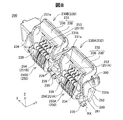
図3は、液体供給ユニット100が装着されている装着状態のカートリッジ装着部27を示す概略斜視図である。カートリッジ装着部27のキャリッジユニット200は、上方が開口している略直方体形状の箱体である。キャリッジユニット200の内部には、液体供給ユニット100が、上面全体が上方に露出している状態で収容されている。印刷ヘッドはキャリッジユニット200の下面に設けられている。
FIG. 3 is a schematic perspective view showing the
液体供給ユニット100の外形は、略直方体形状である。液体供給ユニット100は、内部に1種類のインクを収容している。本実施形態では、液体供給ユニット100は、ブラックの色インクを収容している。なお、他の実施形態では、液体供給ユニット100は、シアンやイエローやマゼンタなどのうちから1種類のカラーインクを収容していても良い。
The external shape of the
A−2.カートリッジ装着部の詳細構成:
図4〜図7を参照してカートリッジ装着部27の概略構成を説明する。図4はカートリッジ装着部27の第1の外観斜視図である。図5はカートリッジ装着部27の第2の外観斜視図である。図6はカートリッジ装着部27の第3の外観斜視図である。図7はカートリッジ装着部27の分解斜視図である。カートリッジ装着部27(図4)は、液体供給ユニット100が装着される第1装着部210Aと第2装着部210Bと有する。第1装着部210Aと第2装着部210Bとを含む装着部210は、5つの壁部201〜205に区画形成されている。第1装着部210Aと第2装着部210Bとを含む装着部210は、鉛直上方向が開口する凹形状である。第1装着部210Aと第2装着部210Bとは、スリット223を有する隔壁221Aによって隔てされている。すなわち、第1装着部210Aと第2装着部210Bとの間には、隔壁221Aが配置されている。
A-2. Detailed configuration of cartridge mounting part:
A schematic configuration of the
底面壁部201は、装着部210の底面を構成している。詳細には、底面壁部201は、外形が略矩形状の底面を構成している。底面壁部201には、底面から立ち上がる複数の隔壁221を有する。複数の隔壁221のうち、第1装着部210Aと第2装着部210Bとの間に位置する隔壁には、符号「221A」を付している。
The
4つの壁部202〜205は、底面壁部201の周縁部から鉛直上方に立ち上がる壁部である。正面壁部202及び背面壁部203はそれぞれ、底面壁部201の正面側の端部および背面側の端部からほぼ鉛直上方に延びている。正面壁部202及び背面壁部203は、装着部210の正面および背面を構成している。第1側面壁部204及び第2側面壁部205はそれぞれ、底面壁部201の左側端部及び右側端部からほぼ鉛直上方に延びている。第1側面壁部204及び第2側面壁部205は、装着部210の左側面および右側面を構成している。
The four
本実施形態では、正面壁部202と背面壁部203と第1側面壁部204と第2側面壁部205とは一体成形によって形成された略四角筒形状を有するキャリッジユニット200の各側壁によって構成されている(図7)。また、底面壁部201は、キャリッジユニット200とは別体として形成され、キャリッジユニット200の底面側開口部に配置されるヘッドユニット207によって構成されている。キャリッジユニット200の正面壁部202には、2つの係合部230と、2つのコネクターユニット250と、配線基板280と、カバー部材300とが、一体的に組み合わされて取り付けられる。
In the present embodiment, the
2つの係合部230はそれぞれ同じ構成を有しており、矢印Xの方向に一列に配設されている(図4〜図6)。2つの係合部230は、液体供給ユニット100をカートリッジ装着部27に着脱する際に用いられるレバーとして機能する。2つの係合部230のうち、第1装着部210Aに設けられた係合部を第1係合部230Aとも呼び、第2装着部210Bに設けられた係合部を第2係合部230Bとも呼ぶ。各係合部230A,230Bは、正面壁部202に対して、矢印Yの方向に回動移動可能に取り付けられている。係合部230は、回動移動によって、液体供給ユニット100の被係合部に係合する(詳細は後述)。なお、本明細書において「係合する」とは、対象物の移動方向が制限されるように当該対象物の所定の部位に係り合うことを意味する。
The two
2つのコネクターユニット250はそれぞれ同じ構成を有しており、2つの係合部230のそれぞれの下方に1つずつ配設されている。コネクターユニット250は、液体供給ユニット100の回路基板(後述)と電気的に接続可能な電極部を有する。2つのコネクターユニット250のうち第1装着部210Aに設けられたコネクターユニットを第1コネクターユニット250Aとも呼び、第2装着部210Bに設けられたコネクターユニットを第2コネクターユニット250Bとも呼ぶ。
Each of the two
配線基板280は、各コネクターユニット250A,250Bと印刷装置10の電気系統とを電気的に接続する。カバー部材300は、配線基板280と正面壁部202との間に配置されており、正面壁部202側から係合部230とコネクターユニット250と配線基板280を一体的にまとめる。
The
底面壁部201の下面には、上述した印刷ヘッド190が取り付けられている(図6)。底面壁部201の上面には、液体導入部211〜214が設けられている(図4,図5)。液体導入部211〜214のうち、第1装着部210Aに設けられた液体導入部211を第1液体導入部211とも呼び、第2装着部210Bに設けられた液体導入部212〜214を第2液体導入部212〜214とも呼ぶ。第1液体導入部211は、液体供給ユニット100が備える液体供給部に接続されて、液体供給ユニット100に収容されたインクが供給される。第1液体導入部211に供給されたインクは、印刷ヘッド190のインク流路に導入される。各液体導入部211〜214の外周には、シール部215が設けられている。シール部215は、インクの経路に対する外気の侵入を抑制するとともに、インクの外部への漏洩を抑制する。
The above-described
第2液体導入部212〜214は、液体供給ユニット100とは接続されず、液体供給ユニット100に収容されたインクは供給されない。一方で、カートリッジ装着部27には、第1装着部210Aのみに装着されるブラックインクを収容する液体供給ユニット(第1カートリッジ)と、第2装着部210Bのみに装着されるカラーインク(シアン、イエロー、マゼンタ)を収容する液体供給ユニット(第2カートリッジ)とが装着される場合がある。この場合、第2カートリッジは、シアンインクを供給する液体供給部と、イエローインクを供給する液体供給部と、マゼンタインクを供給する液体供給部とを備え、これら3つの液体供給部が対応する第2液体導入部212〜214に接続される。
The second
底面壁部201には、付勢機構217が設けられている。付勢機構217は、底面壁部201に載置されている液体供給ユニット100を底面壁部201から離間する方向(上方)に付勢する。本実施形態では、付勢機構217は、弦巻バネによって構成されている。付勢機構217によって、液体供給ユニット100のカートリッジ装着部27への固定性が向上すると共に、液体供給ユニット100が取り外される際の操作性が向上する。
A
底面壁部201には、底面壁部201からの高さが第1側面壁部204及び第2側面壁部205よりも低い第1副壁部221および第2副壁部224が設けられている。第1副壁部221および第2副壁部224は、第1側面壁部204および第2側面壁部205に対して平行である。第1副壁部221は、第1側面壁部204と第2側面壁部205とに隣り合う位置と、第1装着部210Aと第2装着部210Bとの間の位置とに配置されている。ここで、第1装着部210Aと第2装着部210Bとの間に配置された第1副壁部221を「隔壁221A」とも呼ぶ。隔壁221Aは、第1装着部210Aと第2装着部210Bとを隔てている。隔壁221Aは、上端面から底面壁部201まで延びるスリット(切り欠き)223を有する。スリット223は、Y方向の延びる隔壁221Aの途中に形成されている。本実施形態では、スリット223は2つ設けられている。第1副壁部221は、液体供給ユニット100のカートリッジ装着部27に対する位置決め部として機能する。また、第1副壁部221と第2副壁部224とは、液体供給ユニット100の角部が液体導入部211〜214に衝突することを防止する衝突防止部としても機能する。
The
底面壁部201には、背面壁部203に隣接する位置に背面壁部203に対して平行に延びる第3副壁部225が設けられている。第3副壁部225の下端には、複数の嵌合穴227が矢印X方向に配列されている。液体供給ユニット100が装着される際には、X方向の両側に位置する2つの嵌合穴227に液体供給ユニット100の下端に設けられている2つの突起部が挿通される。
The
この他に、底面壁部201には、装着部210と配線基板280の配置領域との間に、コネクターユニット250の下端に向かって突出している隔壁228が設けられている(図5)。また、底面壁部201には、配線基板280の下方に貫通孔229が設けられている(図6)。貫通孔229は印刷装置10のガイドレール28の上に配置される。
In addition, the
図8,図9を用いて係合部230及びコネクターユニット250の説明を以下に行う。図8は、キャリッジユニット200の正面壁部202に取り付けられている状態の係合部230とコネクターユニット250と配線基板280との斜視図である。図9は矢印Xの方向に沿って見たときの係合部230の側面図である。図8,図9にはそれぞれ、係合部230の回動軸RXが図示されている。図9には、キャリッジユニット200におけるコネクターユニット250の配置領域と、キャリッジユニット200に液体供給ユニット100が装着されたときの液体供給ユニット100の被係合機構部120の配置領域と、が破線で図示されている。また、図9には、吹き出し内に、係合部230の第2の脚部231bの端部における取付構造が抜き出して図示されている。
The engaging
係合部230は、下方に向かって開いている矩形枠形状を有しており、第1と第2の脚部231a,231bと、主体部232と、を有する。第1と第2の脚部231a,231bは、底面壁部201から矢印Zの方向に延伸している。第1と第2の脚部231a,231bはほぼ同一の形状を有しており、矢印Xの方向に並列に配列されている。主体部232は、矢印Xの方向に延伸している部位であり、第1と第2の脚部231a,231bの上端に接続されている。
The engaging
係合部230の各脚部231a,231bの下端には矢印Xの方向においてそれぞれ外側に向かって突起する第1凸部235aと、内側に向かって突起している第2凸部235bとが設けられている(図9)。係合部230は、各脚部231a,231bの各第1凸部235aが正面壁部202の下端に設けられている嵌合穴290に嵌合することによって取り付けられている(図9の吹き出し内)。これによって、係合部230は、各第1凸部235aの中心軸を回動軸RXとして前後方向に回動移動可能である。
The lower ends of the
各脚部231a,231bの下端には付勢機構239が設けられている。本実施形態では、付勢機構239はトーションばねによって構成されており、各脚部231a,231bの第2凸部235bに取り付けられている。係合部230は、付勢機構239によって、装着部210に向かって付勢された状態で所定の回動角度で静止するように係止されている。係合部230は、装着部210から離れる方向の外力によって回動移動した後、当該外力が解除されたときには、付勢機構239の付勢力によって、前記の初期位置に戻る。
An
主体部232は、当接部236と、操作部238と、を有する。当接部236は、主体部232において、矢印Yの逆方向側(装着部210側)の端部に位置している。当接部236は、装着部210側の端部の下側の少なくとも一部が、液体供給ユニット100の被係合部(後述)の少なくとも一部に当接する。当接部236の当接によって、液体供給ユニット100の被係合機構部120は、矢印Zの方向に係合される。矢印Zの方向は、液体導入部211から液体供給ユニット100の液体供給部に向かう方向である。この当接によって、液体供給ユニット100の被係合機構部120は、キャリッジユニット200から離れる方向への移動が制限される。
The
本実施形態では、矢印Zの方向は、係合部230の主体部232が液体供給ユニット100の被係合機構部120に係合する方向に一致する。本明細書において「係合する方向」とは、係合する対象に対して係り合う方向であり、当該対象物に対する係合によって移動が制限される方向を意味し、係合する対象に対して係合力を発生させる方向であるとも解釈できる。
In the present embodiment, the direction of the arrow Z coincides with the direction in which the
操作部238は、主体部232において、矢印Yの方向側(前方側)の端部に位置しており、当接部236から上方に向かって曲折している部位である。ユーザーは、操作部238に指先を掛けて引くことによって係合部230を前方に向かって容易に回動移動させることができる。
The
各脚部231a,231bは、ほぼ平板状に構成されており、矢印Y,Zの方向によって規定される平面と平行に配置されている。各脚部231a,231bは、回動軸となる下端部より上側において矢印Yの方向における幅が上方に向かって拡大している。各脚部231a,231bは、主体部232に近い上方の部位に、外周端部が装着部210(図5)に近づくように延出している延出部234が形成されている。
Each of the
ここで、コネクターユニット250は第1と第2の脚部231a,231bの間に配置されている(図9)。コネクターユニット250は液体供給ユニット100の回路基板(後述)と対応する傾斜角(例えば矢印Z方向に対して10°〜45°)を有する状態で、係合部230とは独立して、キャリッジユニット200の正面壁部202に固定されている。
Here, the
係合部230の延出部234は、キャリッジユニット200に液体供給ユニット100が装着されていない初期状態においては、その外周端部がコネクターユニット250の上段電極部253(後述)よりも装着部210に近い位置にある。また、延出部234は、液体供給ユニット100の装着方向である上方(矢印Zの方向)に延出している。延出部234によって、ユーザーの指先が上段電極部253に接触して脂分などの異物が付着しまうことが抑制される。
In the initial state where the
図8に示すように、第1コネクターユニット250Aは、当接部236の下側に位置する第1電極部251Aを有する。第2コネクターユニット250Bは、当接部236の下側に位置する第2電極部251Bを有する。第1と第2電極部251A,251Bはそれぞれ複数の端子(本実施形態では9つの端子)から構成されている。複数の端子は、金属板によって形成されている。第1と第2電極部251A,251Bが備える複数の端子のうち、上側の位置でX方向に沿った列を形成する端子群を上段電極部253とも呼び、上段電極部253よりも下側の位置でX方向に沿った列を形成する端子群を下段電極部254とも呼ぶ。第1と第2の電極部251A,251Bの一部は、配線基板280と接触することによって電気的に接続されている。配線基板280は、配線ケーブルを介して制御部21に電気的に接続されている。
As shown in FIG. 8, the
A−3.液体供給ユニットの外観構成:
図10は、液体供給ユニット100の第1の外観斜視図である。図11は、液体供給ユニット100の第2の外観斜視図である。図12は、液体供給ユニット100を説明するための図である。図12(A)は、液体供給ユニット100の上面図である。図12(B)は、液体供給ユニット100の正面図である。図12(C)は、液体供給ユニット100の底面図である。図10〜12には、印刷装置10に液体供給ユニット100が装着された装着状態における矢印X,Y,Zが図示されている。なお、これ以降に示す図においても同様に、必要に応じて装着状態における矢印X,Y,Zが図示されている。
A-3. Appearance configuration of liquid supply unit:
FIG. 10 is a first external perspective view of the
液体供給ユニット100(図10)の外形は、略直方体形状である。液体供給ユニット100は、外殻を構成する6つの壁部101〜106を有する。外殻は、ポリエチレンやポリスチレンなどの合成樹脂によって形成されている。6つの壁部101〜106によって取り囲まれた内部には、インクを収容するための液体収容室を含む液体収容空間部09が形成されている。つまり、液体供給ユニット100の内側には、インクを収容するための液体収容空間部109が形成されている。壁部101を、第1壁部(底壁部)101とも呼ぶ。壁部102を第2壁部(上壁部)とも呼ぶ。壁部103を、第3壁部(背面壁部)103とも呼ぶ。壁部104を、第4壁部(正面壁部)104とも呼ぶ。壁部105を、第5壁部(左側壁部)105とも呼ぶ。壁部106を、第6壁部(右側壁部)106とも呼ぶ。
The external shape of the liquid supply unit 100 (FIG. 10) is a substantially rectangular parallelepiped shape. The
装着状態において、第1壁部101と第2壁部102とはそれぞれ略水平な壁部を構成し、第3壁部103〜第6壁部106はそれぞれ略垂直な壁部を構成する。
In the mounted state, the
第1壁部101(図11)は、液体供給ユニット100がカートリッジ装着部27に装着された装着状態のときに、底面壁部201(図4)と対向する底面を構成する。第1壁部101には、装着状態において、底面壁部201から突出する隔壁221が挿入される2つの隙間118が形成されている。この隙間118を溝部とも呼ぶ。2つの隙間118のうち、隔壁221A(図4)が挿入される隙間には符号「118A」を付している。隙間118は、液体供給ユニット100が印刷装置10のカートリッジ装着部27に装着されたときに、隔壁221を受け入れる。隙間118Aは、第3壁部103から第4壁部104に亘って形成されている(図12(C))。なお、隙間118の形状は上記に限定されるものではなく、隔壁221を挿入できる程度の長さ(Y方向の寸法)と、深さ(Z方向の寸法)を有していれば良い。
The first wall portion 101 (FIG. 11) constitutes a bottom surface that faces the bottom wall portion 201 (FIG. 4) when the
隙間118Aは、以下のようにも規定できる。すなわち、隙間118Aは、第1液体収容室(第1液体収容部)108Aを区画形成する第1外壁部162A(図11)と、第2液体収容室(第2液体収容部)108Bを区画形成する第2外壁部162B(図10)との間に形成されている。第1外壁部162Aと第2外壁部162Bとは隙間118Aを挟んで対向する。第1外壁部162Aと第2外壁部162Bとは、装着状態において隔壁221Aを挟む。第1外壁部162Aと第2外壁部162Bとはそれぞれ、第1壁部101と交差し、第1壁部101から第2壁部102側に向かって延びる壁部である。第1外壁部162Aと第2外壁部162Bとは、凹形状の隙間118Aの側壁を構成するとも捉えることができる。また、隙間118Aは、第1壁部101に形成された凹部(溝部)であるともいえる。
The
図10に示すように、液体供給ユニット100は、隙間118Aを挟むように位置する第1液体収容室108Aと第2液体収容室108Bとを備える。第1液体収容室108Aと第2液体収容室108Bとは、液体収容空間部109を構成する。第1液体収容室108Aと第2液体収容室108Bとは連通している。第1液体収容室108Aは第1装着部210A(図4)に装着可能であり、第2液体収容室108Bは第2装着部210Bに装着可能である。すなわち、液体供給ユニット100が印刷装置10に装着された装着状態において、第1液体収容室108Aは第1装着部210Aに収容され、第2液体収容室108Bは第2装着部210Bに収容される。なお、第1液体収容室108Aと第2液体収容室108Bとを含む液体供給ユニット100の内部構成については後述する。
As shown in FIG. 10, the
第1壁部101には、第1液体導入部211(図4)にインクを供給可能な液体供給部110が形成されている(図11)。具体的には、液体供給部110は、第1壁部101のうち第1液体収容室108Aを区画形成する部分に形成されている。つまり、第1液体収容室108Aは、液体供給部110を有する。液体供給部110は、第1壁部101に形成された開口(貫通孔)である。液体供給部110は、第1液体収容室108Aの内部空間(液体を収容する空間)と連通している。第1液体収容室108A内には、液体供給部110を塞ぐように供給部側液体保持部材149が配置されている。供給部側液体保持部材149は、インクを保持するための部材である。供給部側液体保持部材149は、インクを保持しつつ、所定の外力(印刷装置10からの吸引力)が加わった場合にインクを第1液体導入部211に流通可能な部材であれば良い。供給部側液体保持部材149は、例えば、ポリウレタンなどで形成されたフォームや、ポリプロピレンを繊維状に加工したものを束ねた繊維部材であっても良い。
The
装着状態では、液体供給部110内に第1液体導入部211の先端側部分が挿入されて、第1液体導入部211の先端が供給部側液体保持部材149と接触する。そして、印刷装置10のポンプ機構(図示せず)によって第1液体導入部211を介して第1液体収容室108A内を吸引することで供給部側液体保持部材149に保持されたインクが第1液体導入部211に流通する。これにより、液体供給ユニット100から印刷装置10へとインクが供給される。
In the mounted state, the tip side portion of the first
第1壁部101のうち、液体供給部110の周縁部には外形が液体供給部110の外形に相似する段差部119が形成されている。段差部119は、第1壁部101の外表面を凹ませた部分である。装着状態では、段差部119にはシール部215が当接する。これによりシール部215よりも外側にインクが漏れ出すことを抑制する。
A stepped
第1壁部101には、更に、3つの凹部112が形成されている。具体的には、3つの凹部112は、第1壁部101のうち第2液体収容室108Bを区画形成する部分に形成されている。つまり、第2液体収容室108Bは、凹部112を有する。装着状態において、3つの凹部112には対応する第2液体導入部212〜214(図4)が挿入される。3つの凹部112は、第1壁部101を貫通しておらず底部(+Z方向側の面部)を有する。3つの凹部112は、装着状態において、対応する第2液体導入部212〜214の先端部(+Z方向側端部)が接触しない程度の深さを有する。3つの凹部112のそれぞれは、周縁部に段差部119を有する。段差部119は、凹部112の底部よりも第1壁部101表面側に位置する。装着状態では、段差部119には、シール部215が当接する。なお、第1壁部101は、装着状態において第2液体導入部212〜214の先端部に存在しているインクが液体供給ユニット100に付着しない形態であれば、凹部112を有さなくても良く、また、凹部112の深さもこれに限定されるものではない。例えば、液体供給ユニット100をカートリッジ装着部27に装着する場合は、第2液体導入部212〜214の先端部を覆う蓋を配置することで、凹部112を省略したり、凹部112が蓋と接触する程度の深さであっても良い。
Three
第2壁部102は、第1液体収容室108Aの内部と第2液体収容室108Bの内部とを挟んで第1壁部101と対向する。第2壁部102は、液体供給ユニット100の上面を構成する。第2壁部102は、第1液体収容室108Aと第2液体収容室108Bとを区画形成する単一の壁部である。第2壁部102には、液体収容空間部109のインクの消費に伴って第2液体収容室108Bに外部の大気を導入するための大気連通路115が形成されている(図10)。大気連通路115は、第2壁部102のうち第2液体収容室108Bを区画形成する部分に形成された開口(貫通孔)である。
The
第3壁部103(図11)は、第1壁部101と第2壁部102と交差する。第3壁部103は、液体供給ユニット100の背面を構成する。第3壁部103には、装着状態において、2つの嵌合穴227(図4)に挿入される2つの突起部114が設けられている。
The third wall 103 (FIG. 11) intersects the
第4壁部104(図10)は、第1壁部101と第2壁部102と交差する。また、第4壁部104は、第1液体収容室108Aの内部と第2液体収容室108Bの内部とを挟んで第3壁部103と対向する。第4壁部104には、2つの被係合機構部120が設けられている。2つの被係合機構部120は、第4壁部104から突出する壁部である。2つの被係合機構部120のうち、隙間118Aに対して第1液体収容室108A側に位置する一方を第1被係合機構部120Aとも呼び、隙間118Aに対して第2液体収容室108B側に位置する他方を第2被係合機構部120Bとも呼ぶ。第1被係合機構部120Aと第2被係合機構部120Bとの構成は同様であるため、区別することなく用いる場合は被係合機構部120を用いる。
The fourth wall portion 104 (FIG. 10) intersects the
第1被係合機構部120Aは、装着状態において、第1係合部230A(図8)と係合する第1被係合部123Aを有する。第1被係合部123Aは、第4壁部104から外方へ突出する板状部材である。装着状態において、第1被係合部123Aは第1係合部230Aの当接部236の真下に位置する。また、装着状態において、第1被係合部123Aは、第1液体導入部211から液体供給部110に向かう方向(+Z方向)に、第1係合部230Aの当接部236に対して当接することによって第1係合部230Aと係合する。
The first
第1被係合機構部120Aは、さらに、第1被係合部123Aよりも第1壁部101側に位置する端子配置面125を有する。端子配置面125は、第1壁部101側に近づくにつれて(すなわち、鉛直下側に向かうに従い)第4壁部104に近づくように傾斜している。端子配置面125には、回路基板130が配置されている。回路基板130は、第1電極部251A(図8)と電気的に接続可能な第1端子部131Aを表面に有する。第1端子部131Aは、第1電極部251Aの端子の数に対応して9つ配置されている。また、回路基板130は、裏面に記憶装置(図示せず)を有する。記憶装置には、液体供給ユニット100に関する各種情報(例えば、インク残量やインク色)が記憶されている。装着状態において、第1端子部131Aと第1電極部251Aとが接触して電気的に接続することで、回路基板130の記憶装置と制御部21との間で信号をやり取りできる。
120 A of 1st to-be-engaged mechanisms have further the terminal arrangement | positioning
第2被係合機構部120Bは、装着状態において、第2係合部230B(図8)と係合する第2被係合部123Bを有する。第2被係合部123Bは、第4壁部104から外方へ突出する板状部材である。装着状態において、第2被係合部123Bは第2係合部230Bの当接部236の真下に位置する。また、装着状態において、第2被係合部123Bは、第1液体導入部211から液体供給部110に向かう方向(+Z方向)に、第2係合部230Bの当接部236に対して当接することによって第2係合部230Bと係合する。
The second
第2被係合機構部120Bは、さらに、第2被係合部123Bよりも第1壁部101側に位置する端子配置面125を有する。端子配置面125は、第1壁部101側に近づくにつれて(すなわち、鉛直下側に向かうに従い)第4壁部104に近づくように傾斜している。端子配置面125には、回路基板130が配置されている。回路基板130は、第2電極部251B(図8)と電気的に接続可能な第2端子部131Bを表面に有する。第2端子部131Bは、第2電極部251Bの端子の数に対応して9つ配置されている。また、回路基板130は、裏面に記憶装置(図示せず)を有する。記憶装置には、液体供給ユニット100に関する各種情報(例えば、インク残量やインク色)が記憶されている。装着状態において、第2端子部131Bと第2電極部251Bとが接触して電気的に接続することで、回路基板130の記憶装置と制御部21との間で信号をやり取りできる。
The second
第5壁部105(図10)は、第1〜第4壁部101〜104と交差する。第6壁部106(図11)は、第1〜第4壁部101〜104と交差する。第5壁部105と第6壁部106とは、第1液体収容室108Aの内部と第2液体収容室108Bの内部とを挟んで対向する。
The fifth wall portion 105 (FIG. 10) intersects with the first to
第1〜第4壁部101〜104は、第1液体収容室108Aと第2液体収容室108Bとを区画形成する。第5壁部105は、第1液体収容室108Aを区画形成し、第2液体収容室108Bを区画形成していない。第6壁部106は、第2液体収容室108Bを区画形成し、第1液体収容室108Aを区画形成していない。
The first to
A−4.液体供給ユニットの詳細構成:
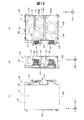
図13は、液体供給ユニット100の底面図である。図14は、液体供給ユニット100を説明するための図である。図15は、装着状態における液体供給ユニット100を説明するための図である。図14(A)は、図13のF13A−F13A断面図である。図14(B)は、図13のF13B−F13B断面図である。図14(C)は、図13のF13C−F13C断面図である。図14(D)は、図13のF13D−F13D断面図である。なお、図13及び図14は、液体供給ユニット100の模式図であり、説明に必要な構成を主に図示している。
A-4. Detailed configuration of the liquid supply unit:
FIG. 13 is a bottom view of the
図14(C)に示すように、液体供給ユニット100は第1液体収容室108Aと第2液体収容室108Bとを連通させる液体連通部140を有する。液体連通部140の一端部143eは、第1液体収容室108A内で開口する。液体連通部140の他端部142eは、第2液体収容室108B内で開口する。液体連通部140は、第1液体流路141と、第2液体流路142と、第3液体流路143とを有する。第2液体収容室108Bから第1液体収容室108Aに向かうインクの流れ方向において、上流側から順に第2液体流路142,第1液体流路141,第3液体流路143が配置されている。第1〜第3液体流路141〜143はそれぞれ、流路方向(液体の流れ方向)が異なる。第1液体流路141の流路方向は、水平方向であって第2液体収容室108Bから第1液体収容室108Aに向かう方向である。第2液体流路142の流路方向は、第1壁部101から第2壁部102に向かう方向(鉛直上方向)である。第3液体流路143の流路方向は、第2壁部102から第1壁部101に向かう方向(鉛直下方向)である。
As shown in FIG. 14C, the
第1液体流路141は、凹状の隙間118Aの底面を構成する第1流路壁171と第2壁部102とによって挟まれて区画形成されている。第2液体流路142は、第2外壁部162Bと第2壁部102から第1壁部101に向かって延びる第1仕切壁部172とによって挟まれて区画形成されている。第3液体流路143は、第1外壁部162Aと第2壁部102から第1壁部101に向かって延びる第2仕切壁部173とによって挟まれて区画形成されている。第1仕切壁部172と第2仕切壁部173とはそれぞれ、第3壁部103から第4壁部104に亘って延びる板状の壁部である。
The first
図15に示すように、装着状態において、液体供給ユニット100を第2壁部102から第1壁部101に向かう方向(以下、「鉛直下方向」という)に向かって平面視したとき、第1液体流路141は隔壁221Aと重なる。本実施形態では、装着状態において、第1液体流路141は隔壁221Aの真上に位置する。また、装着状態において、液体供給ユニット100を鉛直下方向に向かって平面視したとき、第2液体流路142は第2装着部210Bと重なる。つまり、装着状態において、第2液体流路142は第2装着部210B内に位置する。また、装着状態において、液体供給ユニット100を鉛直下方向に向かって平面視したとき、第3液体流路143は第1装着部210Aと重なる。つまり、装着状態において、第3液体流路143は第1装着部210A内に位置する。
As shown in FIG. 15, when the
図14(C)に示すように、第1液体流路141は、第1壁部101よりも第2壁部102に近い位置に設けられている。つまり、第1液体流路141は、第1壁部101と第2壁部102とが対向する方向(Z方向)について、第1壁部101と第2壁部102との中央と、第2壁部102との間に設けられている。本実施形態では、第1液体流路141は、第2壁部102に隣接している。また、第2液体流路142のうち、第2液体収容室108Bに接続された第1端部(他端部)142eは、第1液体流路141よりも第1壁部101に近い位置に設けられている。つまり、装着状態において、第1端部142eは第1液体流路141よりも鉛直下側に位置する。また、第3液体流路143のうち、第1液体収容室108Aに接続された第2端部(一端部)143eは、第1液体流路141よりも第1壁部101に近い位置に設けられている。つまり、装着状態において、第2端部143eは、第1液体流路141よりも第1壁部101に近い位置に設けられている。第1端部142eと第2端部143eとはそれぞれ、第2壁部102よりも第1壁部101に近い位置に設けられている。
As shown in FIG. 14C, the first
図15に示すように、装着状態では、液体導入部211の先端部(上端部)が液体供給部110に挿入されて供給部側液体保持部材149と接触する。これにより、第1液体収容室108Aに収容されたインクが液体供給部110を介して液体導入部211に流通する。第1液体収容室108Aのインクの消費に伴って、大気連通路115から第2液体収容室108Bに大気が導入される。また装着状態では、隔壁221Aは隙間118A内に挿入される。
As shown in FIG. 15, in the mounted state, the distal end portion (upper end portion) of the
上記第1実施形態によれば、液体供給ユニット100が隔壁221Aが挿入される隙間118Aを有する(図15)。これにより、隔壁221Aが液体供給ユニット100のカートリッジ装着部27への装着の障害となることなく、液体供給ユニット100を第1装着部210Aと第2装着部210Bとに亘って配置できる。これにより、第1装着部210Aに装着可能な第1液体収容室108Aに収容されたインクを液体供給部110から液体導入部211に供給することに加え、液体連通部140を介して、第2装着部210Bに装着可能な第2液体収容室108Bに収容されたインクを第1液体収容室108Aに流通させることができる。これにより、液体供給ユニット100が収容できるインクの容量を増大できる。
According to the first embodiment, the
また、上記実施形態によれば、液体供給ユニット100は、第1液体収容室108Aと第2液体収容室108Bとを連通させる液体連通部140を有する(図15)。これにより、第2液体収容室108Bのインクを第1液体収容室108Aに流通させることができる。また、第2液体流路142の第1端部142eは第1液体流路141よりも第1壁部101に近い位置に設けられている(図15)。これにより、第2液体収容室108Bのうち第1液体流路141よりも第1壁部101に近い部分に収容されたインクを第1液体収容室108Aに流通させることができる。また、第3液体流路143の第2端部143eは第1液体流路141よりも第1壁部101に近い位置に設けられている(図15)。
これにより、第2液体収容室108Bに収容されたインクを第1液体収容室108Aのうち第1液体流路141よりも第1壁部101に近い位置に流通させることができる。また、装着状態において、液体供給ユニット100を鉛直下方向に向かって平面視したとき、第1液体流路141は隔壁221Aと重なる(図15)。これにより、第1液体流路141を含む液体連通部140によって、隔壁221Aに妨げられることなく第2液体収容室108Bのインクを第1液体収容室108Aへと流通させることができる。
Further, according to the embodiment, the
Accordingly, the ink stored in the second
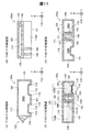
B.第2実施形態:
図16は、第2実施形態としての液体供給ユニット100aの底面図である。図17は、液体供給ユニット100aを説明するための図である。図17(A)は、図16のF16A−F16A断面図である。図17(B)は、図16のF16B−F16B断面図である。図17(C)は、図16のF16C−F16C断面図である。図17(D)は、図16のF16D−F16D断面図である。第2実施形態の液体供給ユニット100aと第1実施形態の液体供給ユニット100の違いは、液体供給ユニット100aが新たに架橋部189を有する点である。その他の構成については液体供給ユニット100aと液体供給ユニット100とでは同様であるため同様の構成について同一符号を付すと共に説明を省略する。また、第2実施形態の液体供給ユニット100aは、第1実施形態の液体供給ユニット100と同様に、カートリッジ装着部27(図4)に着脱自在に装着される。
B. Second embodiment:
FIG. 16 is a bottom view of the
図16,図17(B),図17(D)に示すように、液体供給ユニット100aは、第1外壁部162Aと第2外壁部162Bとを連結する架橋部189を有する。本実施形態では、架橋部189は隔壁221Aのスリット223(図4)の数に対応して2つ設けられている。なお、架橋部189の数はこれに限定されるものではなく、例えばスリット223の数よりも少なくても良い。架橋部189は、対応するスリット223に挿入可能なように構成されている。つまり、装着状態において、架橋部189はスリット223に挿入される。図17(B)に示すように、架橋部189は凹状の隙間118Aの底面(第1流路壁171)から第1壁部101にまで延びる。架橋部189は板状の部材である。架橋部189は、第1壁部101などの外殻と一体成形されている。このように、架橋部189は、隙間118A内において第1外壁部162Aと第2外壁部162Bとを連結する。これにより、隙間118Aを有する液体供給ユニット100aの強度を向上できる。
As shown in FIGS. 16, 17B, and 17D, the
C.第3実施形態:
図18は、第3実施形態としての液体供給ユニット100bの底面図である。図19は、液体供給ユニット100bを説明するための図である。図19(A)は、図18のF18A−F18A断面図である。図19(B)は、図18のF18B−F18B断面図である。図19(C)は、図18のF18C−F18C断面図である。図19(D)は、図18のF18D−F18D断面図である。第3実施形態の液体供給ユニット100bと第2実施形態の液体供給ユニット100aの違いは、架橋部189bに液体連通部140bが設けられている点である。その他の構成については液体供給ユニット100bと液体供給ユニット100aとでは同様であるため同様の構成について同一符号を付すと共に説明を省略する。また、第3実施形態の液体供給ユニット100bは、第1実施形態の液体供給ユニット100と同様に、カートリッジ装着部27(図4)に着脱自在に装着される。
C. Third embodiment:
FIG. 18 is a bottom view of the
図19(B)に示すように、液体供給ユニット100bは、第2実施形態の液体供給ユニット100aと同様に、第1外壁部162Aと第2外壁部162Bとを連結する2つの架橋部189,189bを有する。2つの架橋部189,189bのうち一方の架橋部189bには、液体連通部140bが形成されている。液体連通部140bは、架橋部189bを第1液体収容室108A側から第2液体収容室108B側まで貫通する貫通孔である。液体連通部140bは、第2壁部102よりも第1壁部101に近い位置に設けられている。本実施形態では、液体連通部140bは、第1壁部101と隣接している。
As shown in FIG. 19B, the
上記第3実施形態によれば、液体供給ユニット100bは、架橋部189bに液体連通部140bが設けられている。これにより、架橋部189bを有効に利用して第1液体収容室108Aと第2液体収容室108Bとを連通させることができる。また、液体連通部140bは、架橋部189bのうち、第2壁部102よりも第1壁部101に近い位置に設けられている。これにより、第2液体収容室108Bの第2壁部102よりも第1壁部101に近い部分(底面近傍)に収容されたインクを第1液体収容室108Aに流通させることができる。
According to the third embodiment, the
上記第3実施形態において、液体連通部140bは2つの架橋部189、189bのうちの一方に設けられていたが、2つの架橋部189,189bの両方に設けても良い。また、架橋部189bに設けた液体連通部140bと、第1実施形態の液体連通部140(図14(C))とを併用しても良い。
In the third embodiment, the
D.第4実施形態:
図20は、第4実施形態としての液体供給ユニット100cを説明するための図である。図20は、図14(C)に相当する図である。第4実施形態の液体供給ユニット100cと第1実施形態の液体供給ユニット100(図14)の違いは、液体連通部140cの第1液体流路141cの構成である。その他の構成については液体供給ユニット100cと液体供給ユニット100とでは同様であるため同様の構成について同一符号を付すと共に説明を省略する。また、第4実施形態の液体供給ユニット100cは、第1実施形態の液体供給ユニット100と同様に、カートリッジ装着部27(図4)に着脱自在に装着される。
D. Fourth embodiment:
FIG. 20 is a view for explaining a
第1液体流路141cは可撓性を有するチューブによって構成されている。第2液体流路142cと第3液体流路143cのそれぞれ上端部は、第2壁部102に形成された貫通孔である。第2液体流路142cと第3液体流路143cのそれぞれの貫通孔に接続されるように第1液体流路141cが構成されている。第1液体流路141cは、第1実施形態と同様、隙間118Aや隙間118Aに挿入される隔壁221Aの真上に位置する。
The first
上記実施形態によれば、液体連通部140cの少なくとも一部(第1液体流路141c)がチューブで構成されていることによって、液体連通部140cの設計の自由度を向上できる。特に本実施形態では、液体連通部140cの少なくとも一部(第1液体流路141c)が液体供給ユニット100cの外殻(壁部101〜106)よりも外側に配置されている。これにより、液体連通部140cを設ける際に、液体供給ユニット100cの内部空間の構造に配置位置が制限される可能性を低減できる。
According to the embodiment described above, at least a part of the
上記第4実施形態では、液体連通部140cの少なくとも一部(第1液体流路141c)は可撓性を有するチューブであったがこれに限定されるものではない。例えば、可撓性を有さないチューブであっても良い。
In the fourth embodiment, at least a part of the
E.第5実施形態:
図21は、第5実施形態としての液体供給ユニット100dの底面図である。図22は、液体供給ユニット100dを説明するための図である。図22(A)は、図21のF21A−F21A断面図である。図22(B)は、図21のF21B−F21B断面図である。図22(C)は、図21のF21C−F21C断面図である。図22(D)は、図21のF21D−F21D断面図である。第5実施形態の液体供給ユニット100dと第2実施形態の液体供給ユニット100a(図17)との違いは、第1液体保持部材178を備える点と、架橋部189dが第1壁部101から第2壁部102まで延びている点と、液体連通部140dの構成である。その他の構成については液体供給ユニット100dと液体供給ユニット100aとでは同様であるため同様の構成について同一符号を付すと共に説明を省略する。また、第5実施形態の液体供給ユニット100dは、第1実施形態の液体供給ユニット100と同様に、カートリッジ装着部27(図4)に着脱自在に装着される。
E. Fifth embodiment:
FIG. 21 is a bottom view of the
図22(C)に示すように、液体供給ユニット100dは、第1液体収容室108Aと第2液体収容室108Bと液体連通部140dとに亘って配置された第1液体保持部材178を有する。第1液体保持部材178は、インクを保持するための部材である。第1液体保持部材178は、例えば、ポリウレタンなどで形成されたフォームや、ポリプロピレンを繊維状に加工したものを束ねた繊維部材であっても良い。第2液体保持部材としての供給部側液体保持部材149は、液体供給部110と第1液体保持部材178との間に配置されている。本実施形態では、供給部側液体保持部材149は、液体供給部110と第1液体保持部材178との両方に接するように液体供給部110と第1液体保持部材178との間に配置されている。供給部側液体保持部材149は、第1液体保持部材178よりも毛管力が高い部材であることが好ましい。こうすることで、第1液体収容室108Aのインクを液体供給部110側に向けてより円滑に移動させることができる。
As shown in FIG. 22C, the
液体連通部140dは、第2液体流路142及び第3液体流路143(図14(C))を有することなく、第1液体流路141のみによって形成されている。つまり、液体供給ユニット100dは、第2液体流路142や第3液体流路143を区画形成するための第1仕切壁部172や第2仕切壁部173(図14(C))を有さない。
The
上記第5実施形態によれば、第1液体保持部材178によって第2液体収容室108Bのインクを液体連通部140dを介して第1液体収容室に円滑に移動させることができる。また、供給部側液体保持部材149にインクを保持させることができるため、液体供給部110からインクが漏れ出す可能性を低減できる。
According to the fifth embodiment, the first
F.第6実施形態:
図23は、第6実施形態としての液体供給ユニット100eを説明するための図である。図23は、図14(C)に相当する図である。第6実施形態の液体供給ユニット100eと第1実施形態の液体供給ユニット100(図14)との違いは、液体注入孔330と、栓部材340と、土台部360とを新たに設けた点と、液体保持部材350を第1液体収容室108Aに設けた点と、液体連通部140eの構成である。その他の構成については液体供給ユニット100eと液体供給ユニット100とでは同様であるため同様の構成については同一符号を付すと共に説明を省略する。
F. Sixth embodiment:
FIG. 23 is a diagram for explaining a
液体供給ユニット100eにおいて、大気連通路115は第2壁部102のうち第1液体収容室108Aを区画形成する部分に形成されている。つまり、大気連通路115は、液体供給ユニット100eの外部の大気と第1液体収容室108Aとを連通させる。また、第1液体収容室108Aにはインクを保持するための液体保持部材350が配置されている。この液体保持部材350は、供給部側液体保持部材149と同じ部材であっても良いし、異なる部材であっても良い。液体保持部材350は、第3液体流路143の一端部143eと供給部側液体保持部材149とに接するように配置されている。
In the
また、第2壁部102には、第2液体収容室108Beにインクを注入するための液体注入孔330が形成されている。液体注入孔330によって第2液体収容室108Beに容易にインクを注入できる。また、液体供給ユニット100eは、液体注入孔330を塞ぐための栓部材340であって液体注入孔330に着脱可能に取り付けられる栓部材340を有する。第2液体収容室108Beの底面は、土台部360によって隙間118Aの底面(+Z方向側の端面)まで底上げされている。液体連通部140eは、第1液体流路141と第3液体流路143とを備え、第2液体流路142を備えていない。この液体供給ユニット100eでは、第1液体収容室108AのインクINKの消費に伴って大気連通路115から大気(空気)が導入されると共に、液体連通部140eを介して第2液体収容室108Beから第1液体収容室108AにインクINKが円滑に導入される。なお、図23では、第2液体収容室108Beから第1液体収容室108Aへのインクの流れを矢印で示している。
In addition, a
G.第7実施形態:
図24は、第7実施形態としての液体供給ユニット100fを説明するための図である。図24は、図14(C)に相当する図である。第7実施形態の液体供給ユニット100fと第1実施形態の液体供給ユニット100(図14)との違いは、第2液体収容室108Bに弁機構90を設けた点である。その他の構成については液体供給ユニット100fと液体供給ユニット100とでは同様であるため同様の構成については同一符号を付すと共に説明を省略する。
G. Seventh embodiment:
FIG. 24 is a diagram for explaining a
弁機構90は、弁座914と、膜弁912と、付勢部材としてのコイルばね916とを備える。弁機構90によって、液体収容空間部109内は負圧に維持されている。弁座914は、第2壁部102のうち大気連通路115を取り囲むように第2液体収容室108B内の突出する円環状の凸部である。膜弁912は円板状であり弁座914に当接している。大気連通路115から第2液体収容室108B、液体連通部140を通って第1液体収容室108Aへ流れる流体(例えば、インクや空気)の流れ方向において、膜弁912は第2液体収容室108Bのうち大気連通路115が接続される上流側部分108Bsと、第2液体収容室108Bのうち液体連通部140が接続される下流側部分108Btとの間に配置されている。第1液体収容室108Aのインクが印刷装置10の吸引によって消費され、第2液体収容室108Bの下流側部分108Btの負圧が所定値以上に大きくなった場合、コイルばね916の付勢力に抗して膜弁912が弁座914から離れる方向に移動する。これにより、上流側部分108Bsと下流側部分108Btとが連通状態となり、大気連通路115を介して空気が下流側部分108Btに導入される。下流側部分108Btに大気が導入され下流側部分108Btの負圧が所定値よりも小さくなった場合、膜弁912はコイルばね916の付勢力によって弁座914に当接する。これにより、下流側部分108Btと上流側部分108Bsとは非連通状態となる。
The
上記のように、弁機構90は第2液体収容室108B(詳細には、下流側部分108Bt)の圧力に応じて大気連通路115と第2液体収容室108B(詳細には、下流側部分108Bt)とを連通状態と非連通状態とのいずれかの状態にすることができる。また、弁機構90によって、下流側部分108Bt、液体連通部140、第1液体収容室108Aを含む液体収容空間部109を負圧に維持できることから、液体供給部110からインクが漏れ出す可能性を低減できる。
As described above, the
H.第8実施形態:
図25は、第8実施形態としての液体供給ユニット100gを説明するための図である。図25(A)〜(D)は、図14(A)〜(D)に対応している。第8実施形態の液体供給ユニット100gと第2実施形態の液体供給ユニット100a(図17)との違いは、液体供給ユニット100の凹部112を液体供給部110に置き換えた点と、置き換えた液体供給部110に対応して供給部側液体保持部材149が設けられた点である。その他の構成については液体供給ユニット100gと液体供給ユニット100aとでは同様であるため同様の構成について同一符号を付すと共に説明を省略する。また、第8実施形態の液体供給ユニット100gは、第1実施形態の液体供給ユニット100と同様に、カートリッジ装着部27(図4)に着脱自在に装着される。
H. Eighth embodiment:
FIG. 25 is a diagram for explaining a
第1壁部101のうち、第2液体収容室108Bを区画形成する部分には、3つの第2液体供給部としての液体供給部110が形成されている(図24では2つのみ図示)。第2液体収容室108Bに形成された液体供給部110を第2液体供給部110gとも呼ぶ。第2液体収容室108B内には、第2液体供給部110gを塞ぐように供給部側液体保持部材149が配置されている。
Three
上記第8実施形態によれば、第1外壁部162Aと第2外壁部162Bとを連結し、装着状態において、隔壁221Aのスリット223に挿入される架橋部189を有する。これにより、隙間118Aを有する液体供給ユニット100gの強度を向上できる。また、第2液体収容室108Bに収容されたインクを直接に第2液体導入部212に供給できる。また、第1液体収容室108Aと第2液体収容室108Bとが液体連通部140によって連通しているため、第1液体収容室108Aと第2液体収容室108Bとの間でインクが流通できる。すなわち、一方の液体収容室のインク液面が他方の液体収容室のインク液面よりも下がった場合でも、他方の液体収容室のインクを一方の液体収容室に流通させることができる。
According to the eighth embodiment, the first
I.変形例:
なお、この発明は上記の実施例や実施形態に限られるものではなく、その要旨を逸脱しない範囲において種々の態様において実施することが可能であり、例えば次のような変形も可能である。
I. Variation:
The present invention is not limited to the above-described examples and embodiments, and can be implemented in various modes without departing from the gist thereof. For example, the following modifications are possible.
I−1.第1変形例:
図26は、液体連通部140caの変形例について説明するための図である。図26は、図20に相当する図である。図26に示す液体供給ユニット100caと、図20に示す第4実施形態の液体供給ユニット100cとの違いは第1液体流路141caの構成である。その他の構成については液体供給ユニット100cと液体供給ユニット100caとは同様であるため同様の構成については同一符号を付すと共に説明を省略する。液体連通部140caの少なくとも一部は、第2壁部102に形成されていても良い。この変形例では、液体連通部140caの第1液体流路141caが第2壁部102に形成されている。具体的には、第2壁部102の外表面に溝を形成し、溝を覆うようにシール部材800を第2壁部102に貼り付ける。これにより、第1液体流路141caが形成される。シール部材800はインクを透過しないフィルムである。溝は、第2液体流路142と第3液体流路143とを接続できる形状であれば良く、蛇行形状であっても良いし直線形状であっても良い。こうすることで、第2壁部102を利用して液体連通部140caの少なくとも一部を形成できる。なお、ここでは、第4実施形態の変形例として説明したが、他の実施形態に対して第2壁部102に液体連通部140caの少なくとも一部を形成するという本変形例を適用しても良い。
I-1. First modification:
FIG. 26 is a diagram for describing a modified example of the liquid communication portion 140ca. FIG. 26 corresponds to FIG. The difference between the liquid supply unit 100ca shown in FIG. 26 and the
I−2.第2変形例:
図27は、第6実施形態の変形例としての液体供給ユニット100eaを説明するための図である。第6実施形態では、液体連通部140eは1つであったが、複数設けても良い。例えば、液体供給ユニット100eaは、経路の異なる上側液体連通部140e1と下側液体連通部140e2とを有する。上側液体連通部140e1は、下側液体連通部140e2と第2壁部102との間に位置する。下側液体連通部140e2は、上側液体連通部140e1と隙間118Aとの間に位置する。下側液体連通部140e2の第1端部142eは、第2壁部102よりも第1壁部101に近い位置で第2液体収容室108B内で開口する。下側液体連通部140e2の第2端部143eは、第2壁部102よりも第1壁部101に近い位置で第1液体収容室108A内で開口する。下側液体連通部140e2は、隙間118Aを跨いで第1液体収容室108Aと第2液体収容室108Bとを連通させる流路である。
I-2. Second modification:
FIG. 27 is a diagram for explaining a liquid supply unit 100ea as a modification of the sixth embodiment. In the sixth embodiment, there is one
大気連通路115は、第2液体収容室108Bと外部の大気とを連通させる。なお、第2壁部102のうち、第1液体収容室108Aを区画形成する部分には大気連通路115は形成されていない。第1液体収容室108Aのインクが消費されるに伴って上側液体連通部140e1を通って大気が第1液体収容室108Aに導入され、第2液体収容室108Bのインクは主に下側液体連通部140e2を通って第1液体収容室108Aに導入される。こうすることで、凹状の隙間118Aの底面(+Z方向側の面)よりも下側に第2液体収容室108Bの一部が形成されていた場合でも、第2液体収容室108Bのインクを効率良く第1液体収容室108Aに導入できる。
The
I−3.第3変形例:
上記各実施形態において、大気連通路115は、第2液体収容室108Bに連通していても良く、第1液体収容室108Aに連通していても良く、第1と第2液体収容室108A,108Bのそれぞれに連通しても良い。第1と第2液体収容室108A,108Bのそれぞれに大気連通路115を連通させる場合、例えば、第2壁部102のうち第1液体収容室108Aを区画形成する部分と第2液体収容室108Bを区画形成する部分のそれぞれに貫通孔を形成すれば良い。
I-3. Third modification:
In each of the above embodiments, the
I−4.第4変形例:
本発明は、インクジェットプリンター、及び、インクジェットプリンターにインクを供給するための液体供給ユニットに限らず、インク以外の他の液体を噴射する任意の液体噴射装置及びその液体を収容するための液体供給ユニット(液体収容容器)にも適用することができる。例えば、以下のような各種の液体噴射装置及びその液体供給ユニットに適用可能である。
(1)ファクシミリ装置等の画像記録装置
(2)液晶ディスプレイ等の画像表示装置用のカラーフィルタの製造に用いられる色材噴射装置
(3)有機EL(Electro Luminescence)ディスプレイや、面発光ディスプレイ (Field Emission Display、FED)等の電極形成に用いられる電極材噴射装置
(4)バイオチップ製造に用いられる生体有機物を含む液体を噴射する液体噴射装置
(5)精密ピペットとしての試料噴射装置
(6)潤滑油の噴射装置
(7)樹脂液の噴射装置
(8)時計やカメラ等の精密機械にピンポイントで潤滑油を噴射する液体噴射装置
(9)光通信素子等に用いられる微小半球レンズ(光学レンズ)などを形成するために紫外線硬化樹脂液等の透明樹脂液を基板上に噴射する液体噴射装置
(10)基板などをエッチングするために酸性又はアルカリ性のエッチング液を噴射する液体噴射装置
(11)他の任意の微小量の液滴を吐出させる液体噴射ヘッドを備える液体噴射装置。
I-4. Fourth modification:
The present invention is not limited to an ink jet printer and a liquid supply unit for supplying ink to the ink jet printer, but an arbitrary liquid ejecting apparatus for ejecting liquid other than ink and a liquid supply unit for containing the liquid It can also be applied to (liquid container). For example, the present invention can be applied to the following various liquid ejecting apparatuses and liquid supply units thereof.
(1) Image recording device such as a facsimile machine (2) Color material injection device used for manufacturing a color filter for an image display device such as a liquid crystal display (3) Organic EL (Electro Luminescence) display, surface emitting display (Field Electrode material injection device used for electrode formation such as Emission Display (FED), etc. (4) Liquid injection device for injecting liquid containing biological organic material used for biochip manufacturing (5) Sample injection device as a precision pipette (6) Lubrication Oil injection device (7) Resin liquid injection device (8) Liquid injection device for injecting lubricating oil pinpoint to precision machines such as watches and cameras (9) Micro hemispherical lenses (optical lenses) used in optical communication elements, etc. ), Etc., to inject a transparent resin liquid such as an ultraviolet curable resin liquid onto the substrate (10) Acid or to etch the substrate A liquid ejecting apparatus that ejects alkaline of the etching solution (11) any other liquid ejecting apparatus including a liquid ejecting head ejecting a minute amount of liquid droplet.
なお、「液滴」とは、液体噴射装置から吐出される液体の状態をいい、粒状、涙状、糸状に尾を引くものも含むものとする。また、ここでいう「液体」とは、液体噴射装置が噴射させることができるような材料であれば良い。例えば、「液体」は、物質が液相であるときの状態の材料であれば良く、粘性の高い又は低い液状態の材料、及び、ゾル、ゲル水、その他の無機溶剤、有機溶剤、溶液、液状樹脂、液状金属(金属融液)のような液状態の材料も「液体」に含まれる。また、物質の一状態としての液体のみならず、顔料や金属粒子などの固形物からなる機能材料の粒子が溶媒に溶解、分散または混合されたものなども「液体」に含まれる。また、液体の代表的な例としては上記実施形態で説明したようなインクや液晶等が挙げられる。ここで、インクとは一般的な水性インクおよび油性インク並びにジェルインク、ホットメルトインク等の各種の液体状組成物を包含するものとする。 The “droplet” refers to the state of the liquid ejected from the liquid ejecting apparatus, and includes those that have tails in the form of particles, tears, and threads. The “liquid” here may be any material that can be ejected by the liquid ejecting apparatus. For example, the “liquid” may be a material in a state in which the substance is in a liquid phase, such as a material in a liquid state having high or low viscosity, and sol, gel water, other inorganic solvents, organic solvents, solutions, Liquid materials such as liquid resins and liquid metals (metal melts) are also included in the “liquid”. Further, “liquid” includes not only a liquid as one state of a substance but also a liquid obtained by dissolving, dispersing or mixing particles of a functional material made of a solid such as a pigment or metal particles in a solvent. Further, representative examples of the liquid include ink and liquid crystal as described in the above embodiment. Here, the ink includes various liquid compositions such as general water-based ink and oil-based ink, gel ink, and hot-melt ink.
本発明は、上述の実施形態や実施例、変形例に限られるものではなく、その趣旨を逸脱しない範囲において種々の構成で実現することができる。例えば、発明の概要の欄に記載した各形態中の技術的特徴に対応する実施形態、実施例、変形例中の技術的特徴は、上述の課題の一部又は全部を解決するために、あるいは、上述の効果の一部又は全部を達成するために、適宜、差し替えや、組み合わせを行うことが可能である。また、その技術的特徴が本明細書中に必須なものとして説明されていなければ、適宜、削除することが可能である。例えば、以下の形態としても実現できる。
(1)本発明の一形態によれば、液体導入部を有する第1装着部と、第2装着部と、前記第1装着部と前記第2装着部とを隔て、スリットを有する隔壁と、を備える液体噴射装置に、装着可能な液体供給ユニットが提供される。この液体供給ユニットは、前記第1装着部に装着可能な第1液体収容室であって、前記液体導入部に液体を供給可能な液体供給部を有する第1液体収容室と、前記第2装着部に装着可能な第2液体収容室と、前記第1液体収容室と前記第2液体収容室とを連通させる液体連通部と、を備え、前記第1液体収容室を区画形成する第1外壁部と前記第2液体収容室を区画形成する第2外壁部との間には、前記隔壁を挿入可能な隙間が形成されている。
上記形態によれば、液体供給ユニットが隙間を有することで、隔壁が装着の障害となることなく、液体供給ユニットを第1装着部と第2装着部とに亘って配置できる。これにより、第1装着部に装着可能な第1液体収容室に収容された液体を液体供給部から液体導入部に供給することに加え、液体連通部を介して、第2装着部に装着可能な第2液体収容室に収容された液体を第1液体収容室に流通させることができる。これにより、液体供給ユニットが収容できる液体の容量を増大できる。
(2)本発明の他の一形態によれば、液体導入部と第1電極部と第1係合部とを有する第1装着部と、第2電極部と第2係合部とを有する第2装着部と、前記第1装着部と前記第2装着部とを隔て、スリットを有する隔壁と、を備える液体噴射装置に、装着可能な液体供給ユニットが提供される。この液体供給ユニットは、前記第1装着部に装着可能な第1液体収容室であって、前記液体導入部に液体を供給可能な液体供給部を有する第1液体収容室と、前記第2装着部に装着可能な第2液体収容室と、前記第1液体収容室と前記第2液体収容室とを連通させる液体連通部と、前記第1電極部と電気的に接続可能な第1端子部と、前記第2電極部と電気的に接続可能な第2端子部と、前記液体供給ユニットを前記液体噴射装置に装着した装着状態において、前記液体導入部から前記液体供給部に向かう方向に、前記第1係合部に対して当接可能な第1被係合部と、前記装着状態において、前記液体導入部から前記液体供給部に向かう方向に、前記第2係合部に対して当接可能な第2被係合部と、を備える、前記第1液体収容室を区画形成する第1外壁部と前記第2液体収容室を区画形成する第2外壁部との間には、前記隔壁を挿入可能な隙間が形成されている。
上記形態によれば、液体供給ユニットが隙間を有することで、隔壁が装着の障害となることなく、液体供給ユニットを第1装着部と第2装着部とに亘って配置できる。これにより、第1装着部に装着可能な第1液体収容室に収容された液体を液体供給部から液体導入部に供給することに加え、液体連通部を介して、第2装着部に装着可能な第2液体収容室に収容された液体を第1液体収容室に流通させることができる。これにより、液体供給ユニットが収容できる液体の容量を増大できる。
(3)上記形態の液体供給ユニットであって、前記液体供給ユニットを前記液体噴射装置に装着した装着状態において、前記液体供給ユニットを前記液体供給部が前記液体導入部に対面する対面方向に向かって平面視したとき、
前記液体連通部は、前記隔壁と重なる第1液体流路を含んでも良い。
上記形態によれば、第1液体流路を含む液体連通部によって、隔壁に妨げられることなく第2液体収容室の液体を第1液体収容室へと流通させることができる。
(4)上記形態の液体供給ユニットであって、前記装着状態において、前記液体供給ユニットを前記対面方向に向かって平面視したとき、前記液体連通部は前記第2装着部と重なる第2液体流路を含んでも良い。
上記形態によれば、第2液体流路を含む液体連通部によって、第2液体収容室の液体を第1液体収容室へと流通させることができる。
(5)上記形態の液体供給ユニットであって、前記装着状態において、前記液体供給ユニットを前記対面方向に向かって平面視したとき、前記液体連通部は前記第1装着部と重なる第3液体流路を含んでも良い。
上記形態によれば、第3液体流路を含む液体連通部によって、第2液体収容室の液体を第1液体収容室へと流通させることができる。
(6)上記形態の液体供給ユニットであって、前記第1外壁部と前記第2外壁部とに交差し、前記液体供給部が形成された第1壁部と、前記第1液体収容室の内部と前記第2液体収容室の内部とを挟んで前記前記第1壁部と対向する第2壁部と、を備え、前記第1壁部と前記第2壁部とは、前記第1液体収容室と前記第2液体収容室とを区画形成し、前記第2壁部には、前記隔壁を挿入可能な前記隙間が形成され、前記第1液体流路は、前記第1壁部よりも前記第2壁部に近い位置に設けられていても良い。
上記形態によれば、第1液体流路を含む液体連通部によって、隔壁に妨げられることなく第2液体収容室の液体を第1液体収容室へと流通させることができる。
(7)上記形態の液体供給ユニットであって、前記第1外壁部と前記第2外壁部とに交差し、前記液体供給部が形成された第1壁部と、前記第1液体収容室の内部と前記第2液体収容室の内部とを挟んで前記前記第1壁部と対向する第2壁部と、を備え、前記第1壁部と前記第2壁部とは、前記第1液体収容室と前記第2液体収容室とを区画形成し、前記第2壁部には、前記隔壁を挿入可能な前記隙間が形成され、前記第1液体流路は、前記第1壁部よりも前記第2壁部に近い位置に設けられ、前記第2液体流路は、前記第2液体収容室に接続された第1端部を有し、前記第1端部は前記第1液体流路よりも前記第1壁部に近い位置に設けられていても良い。
上記形態によれば、第2液体流路の第1端部は第1液体流路よりも第1壁部に近い位置に設けられている。これにより、第2液体収容室のうち第1液体流路よりも第1壁部に近い部分に収容された液体を第1液体収容室に流通させることができる。
(8)上記形態の液体供給ユニットであって、前記第1外壁部と前記第2外壁部とに交差し、前記液体供給部が形成された第1壁部と、前記第1液体収容室の内部と前記第2液体収容室の内部とを挟んで前記前記第1壁部と対向する第2壁部と、を備え、前記第1壁部と前記第2壁部とは、前記第1液体収容室と前記第2液体収容室とを区画形成し、前記第2壁部には、前記隔壁を挿入可能な前記隙間が形成され、前記第1液体流路は、前記第1壁部よりも前記第2壁部に近い位置に設けられ、前記第3液体流路は、前記第1液体収容室と連通させる第2端部を有し、前記第2端部は前記第1液体流路よりも前記第1壁部に近い位置に設けられていても良い。
上記形態によれば、第3液体流路の第2端部は第1液体流路よりも第1壁部に近い位置に設けられている。これにより、第2液体収容室に収容された液体を第1液体収容室のうち第1液体流路よりも第1壁部に近い位置に流通させることができる。
(9)上記形態の液体供給ユニットであって、さらに、前記第1外壁部と前記第2外壁部とを連結し、前記隔壁の前記スリットに挿入可能な架橋部を有していても良い。
上記形態によれば、第1外壁部と第2外壁部とを連結し、隔壁のスリットに挿入可能な架橋部を有する。これにより、隙間を有する液体供給ユニットの強度を向上できる。
(10)上記形態の液体供給ユニットであって、前記液体連通部の少なくとも一部は、前記架橋部に設けられていても良い。
上記形態によれば、架橋部を有効に利用して第1液体収容室と第2液体収容室とを連通させることができる。
(11)上記形態の液体供給ユニットであって、前記第1外壁部と前記第2外壁部とに交差し、前記液体供給部が形成された第1壁部と、前記第1液体収容室の内部と前記第2液体収容室の内部とを挟んで前記前記第1壁部と対向する第2壁部と、前記第1外壁部と前記第2外壁部とを連結し、前記隔壁の前記スリットに挿入可能な架橋部、を備え、前記第1壁部と前記第2壁部とは、前記第1液体収容室と前記第2液体収容室とを区画形成し、前記第2壁部には、前記隔壁を挿入可能な前記隙間が形成されており、前記液体連通部の少なくとも一部は、前記架橋部のうち前記第2壁部よりも前記第1壁部に近い位置に設けられていても良い。
上記形態によれば、液体連通部の少なくとも一部は、第2壁部よりも第1壁部に近い位置に設けられている。これにより、第2液体収容室のうち第2壁部よりも第1壁部に近い部分に収容された液体を第1液体収容室に流通させることができる。
(12)上記形態の液体供給ユニットであって、前記液体連通部の少なくとも一部はチューブによって構成されていても良い。
上記形態によれば、液体連通部の少なくとも一部がチューブで構成されていることによって、液体連通部の設計の自由度が向上できる。
(13)上記形態の液体供給ユニットであって、前記第1外壁部と前記第2外壁部とに交差し、前記液体供給部が形成された第1壁部と、前記第1液体収容室の内部と前記第2液体収容室の内部とを挟んで前記前記第1壁部と対向する第2壁部と、を備え、前記第1壁部と前記第2壁部とは、前記第1液体収容室と前記第2液体収容室とを区画形成し、前記液体連通部の少なくとも一部は、前記第2壁部に形成されていても良い。
この形態によれば、第2壁部を利用して液体連通部の少なくとも一部を形成できる。
(14)上記形態の液体供給ユニットであって、さらに、前記第1液体収容室と前記第2液体収容室と前記液体連通部とに亘って配置された第1液体保持部材を有しても良い。
上記形態によれば、第1液体保持部材によって第2液体収容室の液体を液体連通部を介して第1液体収容室に円滑に移動させることができる。
(15)上記形態の液体供給ユニットであって、さらに、前記第1液体収容室のうち、前記液体供給部と前記第1液体保持部材との間に配置された第2液体保持部材を有しても良い。
上記形態によれば、第2液体保持部材に液体を保持させることができる。
(16)上記形態の液体供給ユニットであって、さらに、前記液体供給ユニットの外部の大気と前記第1液体収容室とを連通可能な大気連通路と、前記第1液体収容室に配置された液体保持部材と、を有しても良い。
この形態によれば、第1液体収容室の液体の消費に伴って第2液体収容室の液体を液体連通部を介して第1液体収容室に円滑に導入することができる。
(17)上記形態の液体供給ユニットであって、さらに、前記液体供給ユニットの外部の大気と前記第2液体収容室とを連通可能な大気連通路と、前記第2液体収容室の圧力に応じて、前記大気連通路と前記第2液体収容室とを連通状態と非連通状態とのいずれかの状態とする弁機構と、を有しても良い。
この形態によれば、弁機構によって大気連通路と第2液体収容室との連通状態を切り替えることができる。
(18)上記形態の液体供給ユニットであって、さらに、前記第2液体収容室に前記液体を注入可能な液体注入孔と、前記液体注入孔を塞ぐための栓部材であって、前記液体注入孔に着脱可能な栓部材と、を有しても良い。
この形態によれば、液体注入孔によって第2液体収容室に容易に液体を注入できる。
(19)本発明の他の一形態によれば、第1液体導入部を有する第1装着部と、第2液体導入部を有する第2装着部と、前記第1装着部と前記第2装着部とを隔て、スリットを有する隔壁と、を備える液体噴射装置に、装着可能な液体供給ユニットが提供される。この液体供給ユニットは、前記第1装着部に装着可能な第1液体収容室であって、前記第1液体導入部に液体を供給可能な第1液体供給部を有する第1液体収容室と、前記第2装着部に装着可能な第2液体収容室であって、前記第2液体導入部に液体を供給可能な第2液体供給部を有する第2液体収容室と、前記第1液体収容室を区画形成する第1外壁部と前記第2液体収容室を区画形成する第2外壁部とを連結し、前記隔壁の前記スリットに挿入可能な架橋部と、を備え、前記第1外壁部と前記第2外壁部との間には、前記隔壁を挿入可能な隙間が形成されている。
この形態によれば、第1外壁部と第2外壁部とを連結し、隔壁のスリットに挿入可能な架橋部を有する。これにより、隙間を有する液体供給ユニットの強度を向上できる。また、第2液体収容室に収容された液体を直接に第2液体導入部に供給できる。
(20)上記形態の液体供給ユニットであって、さらに、前記第1液体収容室と前記第2液体収容室とを連通させる液体連通部を有しても良い。
この形態によれば、第1液体収容室と第2液体収容室とが液体連通部によって連通しているため、第1液体収容室と第2液体収容室との間で液体が流通できる。
The present invention is not limited to the above-described embodiments, examples, and modifications, and can be realized with various configurations without departing from the spirit thereof. For example, the technical features in the embodiments, examples, and modifications corresponding to the technical features in each embodiment described in the summary section of the invention are to solve some or all of the above-described problems, or In order to achieve part or all of the above effects, replacement or combination can be performed as appropriate. Further, if the technical feature is not described as essential in the present specification, it can be deleted as appropriate. For example, it can be realized as the following form.
(1) According to one aspect of the present invention, a first mounting part having a liquid introduction part, a second mounting part, a partition wall having a slit across the first mounting part and the second mounting part, A liquid supply unit that can be attached to a liquid ejecting apparatus is provided. The liquid supply unit is a first liquid storage chamber that can be mounted on the first mounting portion, the first liquid storage chamber having a liquid supply portion that can supply a liquid to the liquid introduction portion, and the second mounting chamber. A second liquid storage chamber that can be attached to a portion; and a liquid communication portion that connects the first liquid storage chamber and the second liquid storage chamber, and a first outer wall that defines the first liquid storage chamber A gap into which the partition wall can be inserted is formed between the first liquid storage chamber and the second outer wall portion that defines the second liquid storage chamber.
According to the said form, a liquid supply unit can be arrange | positioned over a 1st mounting part and a 2nd mounting part, without a partition becoming an obstruction | occlusion of mounting | wearing because a liquid supply unit has a clearance gap. As a result, in addition to supplying the liquid stored in the first liquid storage chamber that can be mounted to the first mounting section from the liquid supply section to the liquid introduction section, it can be mounted to the second mounting section via the liquid communication section. The liquid stored in the second liquid storage chamber can be distributed to the first liquid storage chamber. Thereby, the capacity | capacitance of the liquid which a liquid supply unit can accommodate can be increased.
(2) According to another aspect of the invention, the first mounting portion having the liquid introducing portion, the first electrode portion, and the first engaging portion, and the second electrode portion and the second engaging portion are provided. A liquid supply unit that can be mounted on a liquid ejecting apparatus that includes a second mounting portion, and a partition wall having a slit separating the first mounting portion and the second mounting portion is provided. The liquid supply unit is a first liquid storage chamber that can be mounted on the first mounting portion, the first liquid storage chamber having a liquid supply portion that can supply a liquid to the liquid introduction portion, and the second mounting chamber. A second liquid storage chamber that can be attached to the first portion, a liquid communication portion that allows communication between the first liquid storage chamber and the second liquid storage chamber, and a first terminal portion that can be electrically connected to the first electrode portion. And a second terminal portion that can be electrically connected to the second electrode portion, and a mounting state in which the liquid supply unit is attached to the liquid ejecting apparatus, in a direction from the liquid introduction portion toward the liquid supply portion, A first engaged portion capable of abutting against the first engaging portion; and in the mounted state, the first engaging portion contacts the second engaging portion in a direction from the liquid introduction portion toward the liquid supply portion. A second engaged portion that can be contacted, and the first liquid storage chamber is partitioned That between the second outer wall portion and the first outer wall portion defining a second liquid storage chamber, the partition wall insertable gap is formed.
According to the said form, a liquid supply unit can be arrange | positioned over a 1st mounting part and a 2nd mounting part, without a partition becoming an obstruction | occlusion of mounting | wearing because a liquid supply unit has a clearance gap. As a result, in addition to supplying the liquid stored in the first liquid storage chamber that can be mounted to the first mounting section from the liquid supply section to the liquid introduction section, it can be mounted to the second mounting section via the liquid communication section. The liquid stored in the second liquid storage chamber can be distributed to the first liquid storage chamber. Thereby, the capacity | capacitance of the liquid which a liquid supply unit can accommodate can be increased.
(3) The liquid supply unit according to the above aspect, wherein the liquid supply unit is directed in a facing direction in which the liquid supply unit faces the liquid introduction unit when the liquid supply unit is mounted on the liquid ejecting apparatus. When viewed in plan,
The liquid communication part may include a first liquid channel that overlaps the partition wall.
According to the said form, the liquid of a 2nd liquid storage chamber can be distribute | circulated to a 1st liquid storage chamber by the liquid communication part containing a 1st liquid flow path, without being interrupted by a partition.
(4) In the liquid supply unit according to the above aspect, in the mounted state, when the liquid supply unit is viewed in plan in the facing direction, the liquid communication unit overlaps the second mounting unit. It may include roads.
According to the said form, the liquid of a 2nd liquid storage chamber can be distribute | circulated to a 1st liquid storage chamber by the liquid communication part containing a 2nd liquid flow path.
(5) The liquid supply unit according to the above aspect, wherein in the mounted state, the liquid communication unit overlaps the first mounting unit when the liquid supply unit is viewed in plan in the facing direction. It may include roads.
According to the said form, the liquid of a 2nd liquid storage chamber can be distribute | circulated to a 1st liquid storage chamber by the liquid communication part containing a 3rd liquid flow path.
(6) In the liquid supply unit according to the above aspect, the first wall portion intersecting the first outer wall portion and the second outer wall portion and formed with the liquid supply portion, and the first liquid storage chamber A second wall portion opposed to the first wall portion across the interior of the second liquid storage chamber, wherein the first wall portion and the second wall portion are the first liquid The storage chamber and the second liquid storage chamber are partitioned and formed, the gap into which the partition wall can be inserted is formed in the second wall portion, and the first liquid flow path is more than the first wall portion. You may be provided in the position near the said 2nd wall part.
According to the said form, the liquid of a 2nd liquid storage chamber can be distribute | circulated to a 1st liquid storage chamber by the liquid communication part containing a 1st liquid flow path, without being interrupted by a partition.
(7) In the liquid supply unit according to the above aspect, the first wall portion intersecting the first outer wall portion and the second outer wall portion and having the liquid supply portion formed therein, and the first liquid storage chamber A second wall portion opposed to the first wall portion across the interior of the second liquid storage chamber, wherein the first wall portion and the second wall portion are the first liquid The storage chamber and the second liquid storage chamber are partitioned and formed, the gap into which the partition wall can be inserted is formed in the second wall portion, and the first liquid flow path is more than the first wall portion. The second liquid channel is provided at a position close to the second wall, and the second liquid channel has a first end connected to the second liquid storage chamber, and the first end is the first liquid channel. It may be provided at a position closer to the first wall portion.
According to the said form, the 1st end part of the 2nd liquid flow path is provided in the position near a 1st wall part rather than a 1st liquid flow path. Thereby, the liquid accommodated in the part closer to the first wall portion than the first liquid channel in the second liquid accommodating chamber can be circulated into the first liquid accommodating chamber.
(8) In the liquid supply unit according to the above aspect, the first wall portion intersecting the first outer wall portion and the second outer wall portion and formed with the liquid supply portion, and the first liquid storage chamber A second wall portion opposed to the first wall portion across the interior of the second liquid storage chamber, wherein the first wall portion and the second wall portion are the first liquid The storage chamber and the second liquid storage chamber are partitioned and formed, the gap into which the partition wall can be inserted is formed in the second wall portion, and the first liquid flow path is more than the first wall portion. The third liquid channel is provided at a position near the second wall, and the third liquid channel has a second end communicating with the first liquid storage chamber, and the second end is formed by the first liquid channel. May be provided at a position close to the first wall portion.
According to the said form, the 2nd end part of the 3rd liquid flow path is provided in the position near a 1st wall part rather than a 1st liquid flow path. Thereby, the liquid stored in the second liquid storage chamber can be circulated in a position closer to the first wall portion than the first liquid flow path in the first liquid storage chamber.
(9) The liquid supply unit of the above aspect may further include a bridging portion that connects the first outer wall portion and the second outer wall portion and can be inserted into the slit of the partition wall.
According to the said form, it has a bridge | crosslinking part which connects a 1st outer wall part and a 2nd outer wall part, and can be inserted in the slit of a partition. Thereby, the intensity | strength of the liquid supply unit which has a clearance gap can be improved.
(10) In the liquid supply unit according to the above aspect, at least a part of the liquid communication part may be provided in the bridging part.
According to the said form, a 1st liquid storage chamber and a 2nd liquid storage chamber can be connected using a bridge | crosslinking part effectively.
(11) In the liquid supply unit according to the above aspect, the first wall portion intersecting the first outer wall portion and the second outer wall portion and formed with the liquid supply portion, and the first liquid storage chamber The second wall portion facing the first wall portion across the inside and the inside of the second liquid storage chamber, the first outer wall portion and the second outer wall portion are connected, and the slit of the partition wall The first wall portion and the second wall portion define the first liquid storage chamber and the second liquid storage chamber, and the second wall portion includes The gap into which the partition wall can be inserted is formed, and at least a part of the liquid communication part is provided in a position closer to the first wall part than the second wall part in the bridging part. Also good.
According to the said form, at least one part of the liquid communication part is provided in the position close | similar to a 1st wall part rather than a 2nd wall part. Thereby, the liquid accommodated in the part closer to the 1st wall part than the 2nd wall part among 2nd liquid accommodation chambers can be distribute | circulated to a 1st liquid storage chamber.
(12) In the liquid supply unit according to the above aspect, at least a part of the liquid communication portion may be constituted by a tube.
According to the said form, when at least one part of the liquid communication part is comprised with the tube, the freedom degree of design of a liquid communication part can be improved.
(13) In the liquid supply unit according to the above aspect, the first wall portion intersecting the first outer wall portion and the second outer wall portion and having the liquid supply portion formed therein, and the first liquid storage chamber A second wall portion opposed to the first wall portion across the interior of the second liquid storage chamber, wherein the first wall portion and the second wall portion are the first liquid The storage chamber and the second liquid storage chamber may be partitioned and at least a part of the liquid communication portion may be formed on the second wall portion.
According to this aspect, at least a part of the liquid communication portion can be formed using the second wall portion.
(14) The liquid supply unit of the above aspect may further include a first liquid holding member disposed across the first liquid storage chamber, the second liquid storage chamber, and the liquid communication portion. good.
According to the said form, the liquid of a 2nd liquid storage chamber can be smoothly moved to a 1st liquid storage chamber via a liquid communication part by a 1st liquid holding member.
(15) The liquid supply unit according to the above aspect, further including a second liquid holding member disposed between the liquid supply unit and the first liquid holding member in the first liquid storage chamber. May be.
According to the said form, a 2nd liquid holding member can hold | maintain a liquid.
(16) In the liquid supply unit according to the above aspect, the liquid supply unit is further disposed in the first liquid storage chamber, and an air communication path capable of communicating the atmosphere outside the liquid supply unit with the first liquid storage chamber. And a liquid holding member.
According to this aspect, the liquid in the second liquid storage chamber can be smoothly introduced into the first liquid storage chamber via the liquid communication portion as the liquid in the first liquid storage chamber is consumed.
(17) The liquid supply unit according to the above aspect, and further, an air communication path capable of communicating the atmosphere outside the liquid supply unit and the second liquid storage chamber, and the pressure of the second liquid storage chamber And a valve mechanism for bringing the atmosphere communication path and the second liquid storage chamber into a communication state or a non-communication state.
According to this aspect, the communication state between the atmosphere communication path and the second liquid storage chamber can be switched by the valve mechanism.
(18) The liquid supply unit according to the above aspect, further comprising a liquid injection hole capable of injecting the liquid into the second liquid storage chamber, and a plug member for closing the liquid injection hole, wherein the liquid injection And a plug member that can be attached to and detached from the hole.
According to this aspect, the liquid can be easily injected into the second liquid storage chamber through the liquid injection hole.
(19) According to another aspect of the invention, a first mounting portion having a first liquid introduction portion, a second mounting portion having a second liquid introduction portion, the first mounting portion, and the second mounting portion. A liquid supply unit that can be attached to a liquid ejecting apparatus including a partition having a slit and a partition having a slit is provided. The liquid supply unit is a first liquid storage chamber that can be mounted on the first mounting portion, and has a first liquid supply portion that can supply a liquid to the first liquid introduction portion; and A second liquid storage chamber that can be mounted in the second mounting section, the second liquid storage chamber having a second liquid supply section capable of supplying a liquid to the second liquid introduction section; and the first liquid storage chamber A first outer wall portion that partitions the second liquid wall and a second outer wall portion that partitions and forms the second liquid storage chamber, and a bridging portion that can be inserted into the slit of the partition wall, the first outer wall portion comprising: A gap into which the partition wall can be inserted is formed between the second outer wall portion and the second outer wall portion.
According to this aspect, the first outer wall portion and the second outer wall portion are connected to each other, and the bridge portion that can be inserted into the slit of the partition wall is provided. Thereby, the intensity | strength of the liquid supply unit which has a clearance gap can be improved. In addition, the liquid stored in the second liquid storage chamber can be directly supplied to the second liquid introduction unit.
(20) The liquid supply unit according to the above aspect may further include a liquid communication unit that communicates the first liquid storage chamber and the second liquid storage chamber.
According to this aspect, since the first liquid storage chamber and the second liquid storage chamber communicate with each other through the liquid communication portion, the liquid can flow between the first liquid storage chamber and the second liquid storage chamber.
10…印刷装置
11…筐体
12…給紙口
13…上面カバー
14…排紙口
16…操作部
20…印刷機構部
21…制御部
22…搬送部
23…印刷部
25…搬送ローラー
27…カートリッジ装着部
28…ガイドレール
90…弁機構
100,100a〜100g,100ca,100ea,…液体供給ユニット
101…第1壁部
102…第2壁部
103…第3壁部
104…第4壁部
105…第5壁部
106…第6壁部
108A…第1液体収容室
108B,100Be…第2液体収容室
108Bs…上流側部分
108Bt…下流側部分
109…液体収容空間部
110…液体供給部
110g…第2液体供給部
112…凹部
114…突起部
115…大気連通路
118…隙間
118A…隙間
119…段差部
123A…第1被係合部
123B…第2被係合部
125…端子配置面
120…被係合機構部
120A…第1被係合機構部
120B…第2被係合機構部
130…回路基板
131A…第1端子部
131B…第2端子部
140,140b,140c,140ca,140d…液体連通部
141,141c,141ca…第1液体流路
142,142c…第2液体流路
142e…他端部(第1端部)
143,143c…第3液体流路
143e…一端部(第2端部)
149…供給部側液体保持部材
162A…第1外壁部
162B…第2外壁部
171…第1流路壁
172…第1仕切壁部
173…第2仕切壁部
178…第1液体保持部材
189,189b,189d…架橋部
190…印刷ヘッド
200…キャリッジユニット
201…底面壁部
202…正面壁部
203…背面壁部
204…第1側面壁部
205…第2側面壁部
207…ヘッドユニット
210…装着部
210A…第1装着部
210B…第2装着部
211…第1液体導入部
212…第2液体導入部
215…シール部
217…付勢機構
221…第1副壁部(隔壁)
221A…隔壁
223…スリット
224…第2副壁部
225…第3副壁部
227…嵌合穴
228…隔壁
229…貫通孔
230…係合部
230A…第1係合部
230B…第2係合部
231a…第2の脚部
231b…第2の脚部
232…主体部
234…延出部
235a…第1凸部
235b…第2凸部
236…当接部
238…操作部
239…付勢機構
250…コネクターユニット
250A…第1コネクターユニット
250B…第2コネクターユニット
251A…第1電極部
251B…第2電極部
253…上段電極部
254…下段電極部
280…配線基板
290…嵌合穴
300…カバー部材
330…液体注入孔
340…栓部材
350…液体保持部材
360…土台部
800…シール部材
912…膜弁
914…弁座
1000…液体噴射システム
140e1…上側液体連通部
140e2…下側液体連通部
DESCRIPTION OF
143, 143c ... third
149 ... Supply unit side
221A ...
Claims (9)
底壁部と、
前記底壁部と対向する上壁部と、
前記上壁部と前記底壁部とに交差する第1外壁部及び第2外壁部と、
前記第1外壁部によって区画形成され、前記液体供給ユニットを前記液体噴射装置に装着した装着状態において、前記第1装着部に装着される第1液体収容室と、
前記第2外壁部によって区画形成され、前記装着状態において前記第2装着部に装着される第2液体収容室と、
前記底壁部に、前記第1液体収容室と連通するように設けられ、前記装着状態において、前記液体導入部に接続され、前記液体導入部に液体を供給する液体供給部と、
前記第1液体収容室と前記第2液体収容室とを連通させる液体連通部と、を備え、
前記第1外壁部と前記第2外壁部との間には、前記装着状態において、前記隔壁が挿入される隙間が形成されており、
前記液体供給ユニットは、さらに、
前記装着状態において、前記液体噴射装置の前記第1装着部に設けられた第1電極部と電気的に接続される第1端子部と、
前記装着状態において、前記液体噴射装置の前記第2装着部に設けられた第2電極部と電気的に接続される第2端子部と、
前記装着状態において、前記液体噴射装置の前記第1装着部に設けられた第1係合部と係合する第1被係合部と、
前記装着状態において、前記液体噴射装置の前記第2装着部に設けられた第2係合部と係合する第2被係合部と、を備える、液体供給ユニット。 A liquid supply that can be mounted on a liquid ejecting apparatus that includes a first mounting portion having a liquid introduction portion, a second mounting portion, and a partition wall having a slit separating the first mounting portion and the second mounting portion. A unit,
The bottom wall,
An upper wall facing the bottom wall,
A first outer wall portion and a second outer wall portion intersecting the upper wall portion and the bottom wall portion;
A first liquid storage chamber that is partitioned by the first outer wall portion and is mounted on the first mounting portion in a mounting state in which the liquid supply unit is mounted on the liquid ejecting apparatus;
A second liquid storage chamber defined by the second outer wall portion and mounted to the second mounting portion in the mounting state;
A liquid supply section provided on the bottom wall portion so as to communicate with the first liquid storage chamber, connected to the liquid introduction section in the mounted state, and for supplying a liquid to the liquid introduction section;
A liquid communication part for communicating the first liquid storage chamber and the second liquid storage chamber;
Between the first outer wall portion and the second outer wall portion, a gap into which the partition wall is inserted is formed in the mounted state ,
The liquid supply unit further includes:
A first terminal portion electrically connected to a first electrode portion provided in the first mounting portion of the liquid ejecting apparatus in the mounting state;
A second terminal portion electrically connected to a second electrode portion provided in the second mounting portion of the liquid ejecting apparatus in the mounting state;
A first engaged portion that engages with a first engaging portion provided in the first mounting portion of the liquid ejecting apparatus in the mounted state;
A liquid supply unit comprising: a second engaged portion that engages with a second engaging portion provided in the second mounting portion of the liquid ejecting apparatus in the mounting state .
前記液体連通部は第1液体流路を含み、
前記装着状態において、前記液体供給ユニットを前記上壁部から前記底壁部に向かう鉛直下方向に向かって平面視したとき、前記第1液体流路は前記隔壁と重なる、液体供給ユニット。 The liquid supply unit according to claim 1 ,
The liquid communication part includes a first liquid channel,
In the mounted state, when the liquid supply unit is viewed in a plan view in a vertically downward direction from the upper wall portion toward the bottom wall portion, the first liquid channel overlaps the partition wall.
前記第1外壁部と前記第2外壁部とを連結する架橋部を有し、
前記架橋部は、前記装着状態において前記隔壁の前記スリットに挿入される、液体供給ユニット。 The liquid supply unit according to claim 1 , further comprising:
A bridging portion that connects the first outer wall portion and the second outer wall portion;
The bridging portion is a liquid supply unit that is inserted into the slit of the partition wall in the mounted state.
前記液体連通部の少なくとも一部はチューブによって構成されている、液体供給ユニット。 The liquid supply unit according to any one of claims 1 to 3 ,
The liquid supply unit, wherein at least a part of the liquid communication part is constituted by a tube.
前記液体連通部の少なくとも一部は、前記上壁部に形成されている、液体供給ユニット。 A liquid supply unit according to any one of claims 1 to 4 ,
The liquid supply unit, wherein at least a part of the liquid communication part is formed on the upper wall part.
前記第1液体収容室と前記第2液体収容室と前記液体連通部とに亘って配置された第1液体保持部材を有する、液体供給ユニット。 The liquid supply unit according to any one of claims 1 to 5 , further comprising:
A liquid supply unit having a first liquid holding member disposed across the first liquid storage chamber, the second liquid storage chamber, and the liquid communication portion.
前記液体供給ユニットの外部の大気と前記第1液体収容室とを連通する大気連通路と、
前記第1液体収容室に配置された液体保持部材と、を有する、液体供給ユニット。 The liquid supply unit according to any one of claims 1 to 5 , further comprising:
An atmosphere communication path communicating the atmosphere outside the liquid supply unit with the first liquid storage chamber;
And a liquid holding member disposed in the first liquid storage chamber.
前記液体供給ユニットの外部の大気と前記第2液体収容室とを連通する大気連通路と、
前記第2液体収容室の圧力に応じて、前記大気連通路と前記第2液体収容室とを連通状態と非連通状態とのいずれかの状態とする弁機構と、を有する、液体供給ユニット。 The liquid supply unit according to any one of claims 1 to 5 , further comprising:
An atmosphere communication path communicating the atmosphere outside the liquid supply unit with the second liquid storage chamber;
A liquid supply unit, comprising: a valve mechanism that brings the atmosphere communication path and the second liquid storage chamber into a communication state or a non-communication state according to the pressure of the second liquid storage chamber.
前記第2液体収容室に前記液体を注入可能な液体注入孔と、
前記液体注入孔を塞ぐための栓部材であって、前記液体注入孔に着脱可能な栓部材と、を有する、液体供給ユニット。 The liquid supply unit according to any one of claims 1 to 8 , further comprising:
A liquid injection hole capable of injecting the liquid into the second liquid storage chamber;
A liquid supply unit comprising: a plug member for closing the liquid injection hole, wherein the plug member is detachable from the liquid injection hole.
Priority Applications (3)
| Application Number | Priority Date | Filing Date | Title |
|---|---|---|---|
| JP2015155742A JP6610068B2 (en) | 2015-08-06 | 2015-08-06 | Liquid supply unit |
| US15/224,750 US9636917B2 (en) | 2015-08-06 | 2016-08-01 | Liquid supply unit |
| CN201610639786.0A CN106427221B (en) | 2015-08-06 | 2016-08-05 | Liquid supplying unit |
Applications Claiming Priority (1)
| Application Number | Priority Date | Filing Date | Title |
|---|---|---|---|
| JP2015155742A JP6610068B2 (en) | 2015-08-06 | 2015-08-06 | Liquid supply unit |
Publications (3)
| Publication Number | Publication Date |
|---|---|
| JP2017030323A JP2017030323A (en) | 2017-02-09 |
| JP2017030323A5 JP2017030323A5 (en) | 2018-09-13 |
| JP6610068B2 true JP6610068B2 (en) | 2019-11-27 |
Family
ID=57986991
Family Applications (1)
| Application Number | Title | Priority Date | Filing Date |
|---|---|---|---|
| JP2015155742A Expired - Fee Related JP6610068B2 (en) | 2015-08-06 | 2015-08-06 | Liquid supply unit |
Country Status (3)
| Country | Link |
|---|---|
| US (1) | US9636917B2 (en) |
| JP (1) | JP6610068B2 (en) |
| CN (1) | CN106427221B (en) |
Families Citing this family (2)
| Publication number | Priority date | Publication date | Assignee | Title |
|---|---|---|---|---|
| US10040295B2 (en) * | 2016-02-29 | 2018-08-07 | Seiko Epson Corporation | Liquid supply device, and liquid ejection system |
| JP7172297B2 (en) * | 2018-08-31 | 2022-11-16 | セイコーエプソン株式会社 | inkjet printer |
Family Cites Families (6)
| Publication number | Priority date | Publication date | Assignee | Title |
|---|---|---|---|---|
| JP3106046B2 (en) * | 1993-11-29 | 2000-11-06 | キヤノン株式会社 | Ink cartridge, inkjet recording unit, and recording apparatus using the recording unit |
| JPH0760978A (en) * | 1993-08-23 | 1995-03-07 | Canon Inc | Ink cartridge for replacement type ink jet |
| CA2156809C (en) * | 1994-08-24 | 2003-11-11 | Hiroyuki Inoue | Ink container for ink jet printer, holder for the container carriage for the holder and ink jet printer |
| JPH09174868A (en) * | 1995-12-25 | 1997-07-08 | Canon Inc | Ink-refilling device |
| US6030073A (en) * | 1997-03-03 | 2000-02-29 | Hewlett-Packard Company | Space-efficient enclosure shape for nesting together a plurality of replaceable ink supply bags |
| JP5288743B2 (en) | 2006-08-23 | 2013-09-11 | キヤノン株式会社 | Ink tank and ink jet recording apparatus |
-
2015
- 2015-08-06 JP JP2015155742A patent/JP6610068B2/en not_active Expired - Fee Related
-
2016
- 2016-08-01 US US15/224,750 patent/US9636917B2/en active Active
- 2016-08-05 CN CN201610639786.0A patent/CN106427221B/en not_active Expired - Fee Related
Also Published As
| Publication number | Publication date |
|---|---|
| CN106427221B (en) | 2018-04-06 |
| US9636917B2 (en) | 2017-05-02 |
| CN106427221A (en) | 2017-02-22 |
| US20170036449A1 (en) | 2017-02-09 |
| JP2017030323A (en) | 2017-02-09 |
Similar Documents
| Publication | Publication Date | Title |
|---|---|---|
| JP5700168B2 (en) | Liquid container, printing system, printing apparatus, and terminal connection structure | |
| CN106004060B (en) | cartridge and liquid ejecting apparatus | |
| WO2015093008A1 (en) | Liquid supply unit | |
| EP2837499B1 (en) | Cartridge and sealing member | |
| JP2019104163A (en) | Tank and liquid injection device | |
| WO2017115582A1 (en) | Liquid supply unit | |
| JP6528564B2 (en) | Liquid supply unit | |
| US20220297437A1 (en) | Cartridge | |
| JP5533560B2 (en) | Liquid consumption device | |
| JP6610068B2 (en) | Liquid supply unit | |
| JP2017094660A (en) | Liquid supply unit | |
| WO2017090374A1 (en) | Liquid supply unit and liquid ejection device | |
| JP2014014948A (en) | Cartridge | |
| JP5326703B2 (en) | Liquid container | |
| JP6056723B2 (en) | Cartridge and cap | |
| JP6287325B2 (en) | Liquid supply unit | |
| JP6070235B2 (en) | cartridge | |
| JP2017030323A5 (en) | ||
| US9475295B2 (en) | Liquid ejecting apparatus and liquid supply unit | |
| JP7047452B2 (en) | Ink connection needle, ink filling jig, cartridge | |
| JP6540772B2 (en) | Liquid supply unit | |
| JP2017043061A (en) | Liquid supply unit | |
| JP5725056B2 (en) | Liquid container | |
| JP6295757B2 (en) | Liquid supply unit | |
| JP2017154250A (en) | Liquid supply apparatus and liquid jet system |
Legal Events
| Date | Code | Title | Description |
|---|---|---|---|
| A521 | Request for written amendment filed |
Free format text: JAPANESE INTERMEDIATE CODE: A523 Effective date: 20180802 |
|
| A621 | Written request for application examination |
Free format text: JAPANESE INTERMEDIATE CODE: A621 Effective date: 20180802 |
|
| A977 | Report on retrieval |
Free format text: JAPANESE INTERMEDIATE CODE: A971007 Effective date: 20190717 |
|
| A131 | Notification of reasons for refusal |
Free format text: JAPANESE INTERMEDIATE CODE: A131 Effective date: 20190723 |
|
| A521 | Request for written amendment filed |
Free format text: JAPANESE INTERMEDIATE CODE: A523 Effective date: 20190919 |
|
| TRDD | Decision of grant or rejection written | ||
| A01 | Written decision to grant a patent or to grant a registration (utility model) |
Free format text: JAPANESE INTERMEDIATE CODE: A01 Effective date: 20191001 |
|
| A61 | First payment of annual fees (during grant procedure) |
Free format text: JAPANESE INTERMEDIATE CODE: A61 Effective date: 20191014 |
|
| R150 | Certificate of patent or registration of utility model |
Ref document number: 6610068 Country of ref document: JP Free format text: JAPANESE INTERMEDIATE CODE: R150 |
|
| LAPS | Cancellation because of no payment of annual fees |