JP6608324B2 - Power plant output control apparatus and method - Google Patents
Power plant output control apparatus and method Download PDFInfo
- Publication number
- JP6608324B2 JP6608324B2 JP2016083756A JP2016083756A JP6608324B2 JP 6608324 B2 JP6608324 B2 JP 6608324B2 JP 2016083756 A JP2016083756 A JP 2016083756A JP 2016083756 A JP2016083756 A JP 2016083756A JP 6608324 B2 JP6608324 B2 JP 6608324B2
- Authority
- JP
- Japan
- Prior art keywords
- output
- generator
- control device
- extraction
- power plant
- Prior art date
- Legal status (The legal status is an assumption and is not a legal conclusion. Google has not performed a legal analysis and makes no representation as to the accuracy of the status listed.)
- Active
Links
Images


Classifications
-
- Y—GENERAL TAGGING OF NEW TECHNOLOGICAL DEVELOPMENTS; GENERAL TAGGING OF CROSS-SECTIONAL TECHNOLOGIES SPANNING OVER SEVERAL SECTIONS OF THE IPC; TECHNICAL SUBJECTS COVERED BY FORMER USPC CROSS-REFERENCE ART COLLECTIONS [XRACs] AND DIGESTS
- Y02—TECHNOLOGIES OR APPLICATIONS FOR MITIGATION OR ADAPTATION AGAINST CLIMATE CHANGE
- Y02E—REDUCTION OF GREENHOUSE GAS [GHG] EMISSIONS, RELATED TO ENERGY GENERATION, TRANSMISSION OR DISTRIBUTION
- Y02E30/00—Energy generation of nuclear origin
Landscapes
- Monitoring And Testing Of Nuclear Reactors (AREA)
Description
本発明は原子力プラントの出力制御装置及び方法に係り、特に、タービン・発電機へ送出する主蒸気からの抽気量を制御して発電機の出力を制御する原子力プラントの出力制御装置及び方法に関する。 The present invention relates to an output control apparatus and method for a nuclear power plant, and more particularly to an output control apparatus and method for a nuclear power plant that controls the output of a generator by controlling the amount of extraction from main steam sent to a turbine / generator.
従来、沸騰水型原子力プラントにおける発電機出力制御は、目標発電機出力値と現在の実発電機出力値との間に偏差が生じた場合、まず偏差に応じて原子炉出力を調整し、その後原子炉出力に応じた蒸気をタービンに送ることで実発電機出力を目標値に調整している。すなわち、原子炉内の圧力が急変しないように、原子炉から送りだされる蒸気(以下、主蒸気と記す)の量を調整している。これは、沸騰水型の原子炉において、原子炉内の圧力が急変すると冷却材内の蒸気泡(以下、ボイドと記す)の状態が変わり、原子炉の出力が変化するためである。 Conventionally, the generator output control in a boiling water nuclear power plant, when a deviation occurs between the target generator output value and the current actual generator output value, first adjust the reactor output according to the deviation, then The actual generator output is adjusted to the target value by sending steam according to the reactor power to the turbine. That is, the amount of steam sent from the reactor (hereinafter referred to as main steam) is adjusted so that the pressure in the reactor does not change suddenly. This is because in a boiling water reactor, when the pressure in the reactor changes suddenly, the state of steam bubbles (hereinafter referred to as voids) in the coolant changes and the output of the reactor changes.
特許文献1には、従来の出力制御装置の一例が示されている。この例では、目標発電機出力と実際の発電機出力との偏差に基づいて再循環ポンプ速度要求信号が出力され、原子炉の出力が変化し、原子炉の出力変更により原子炉から発生する蒸気量が変化してタービン入口圧力が変化する。そして、タービン入口圧力の変化に比例して、タービン加減弁の開度が調整され、タービンへの蒸気量が調整されることにより実際の出力が目標発電機出力に一致するように制御される。このような従来の制御方式において、特許文献1には、目標発電機出力と実際の発電機出力の制御遅れを抑制することを目的として、本来の目標発電機出力とは別に、制御用の目標発電機出力を設定し、これにより制御遅れを先行的に補償する出力制御方法が開示されている。 Patent Document 1 shows an example of a conventional output control device. In this example, the recirculation pump speed request signal is output based on the deviation between the target generator output and the actual generator output, the reactor output changes, and the steam generated from the reactor due to the reactor output change is changed. The amount changes and the turbine inlet pressure changes. Then, the opening of the turbine control valve is adjusted in proportion to the change in the turbine inlet pressure, and the actual output is controlled to match the target generator output by adjusting the steam amount to the turbine. In such a conventional control method, Patent Document 1 describes a control target separately from the original target generator output for the purpose of suppressing the control delay between the target generator output and the actual generator output. An output control method is disclosed in which a generator output is set, thereby compensating for control delay in advance.
また、特許文献2には、再循環流量制御、制御棒操作に加え、給水温度調節機構により原子炉の出力制御を行う原子炉給水温度制御装置が開示されている。この制御装置では、給水加熱器に接続する抽気配管に制御弁を設け、給水温度を調節する。給水温度を降下させて運転することにより、冷却水の炉心入口サブクーリングが上がり、ボイド率が下がり、炉心反応度が上がり、原子炉出力を上げることができる。
Further,
電力系統内において、従来の原子力プラントの多くは基底負荷運転、すなわち出力一定で運転し、需要の変化に合わせて供給する電力量を調整する役割は水力発電や火力発電が担っていた。しかし、近年、自然エネルギーの増加やこれに伴う火力発電の減少が進む地域などにおいては、原子力発電の発電機出力を変化させる負荷追従運転が要望されてきている。 In the electric power system, most of the conventional nuclear power plants operate at base load, that is, operate at a constant output, and the role of adjusting the amount of electric power to be supplied according to the change in demand was played by hydroelectric power generation and thermal power generation. However, in recent years, load follow-up operation that changes the generator output of nuclear power generation has been demanded in areas where the increase in natural energy and the decrease in thermal power generation accompanying this increase.
負荷追従運転は、変更出力の大きさと周期によっていくつかのカテゴリに分類される。日負荷追従運転と呼ばれる運転では、昼夜での需要の変動に合わせて、昼間に発電機出力を大きくし、夜間に発電機出力を抑制する。出力の変更幅は最大で定格の50%を超えるケースもあるが、数時間かけて出力を変更するため速応答は要求されない。一方、周波数制御運転と呼ばれる運転では、系統内の周波数を一定に保つように、数秒から数分程度の時間で変化する電力需要に合わせて発電機出力を調整する運転であり、出力変化幅は高々10%程度と小さいが、速応答が要求される。 Load following operation is classified into several categories according to the magnitude and cycle of the change output. In the operation called daily load following operation, the generator output is increased during the day and the generator output is suppressed at night according to fluctuations in demand during the day and night. The output change range may exceed 50% of the rating at the maximum, but since the output is changed over several hours, a quick response is not required. On the other hand, in the operation called frequency control operation, in order to keep the frequency in the system constant, the generator output is adjusted according to the power demand that changes in a time from several seconds to several minutes, and the output change width is Although it is as small as 10% at most, quick response is required.
上述したように、沸騰水型原子炉においては、発電機出力を調整するために、まず再循環ポンプ速度や制御棒位置を制御して原子炉の出力を変更し、出力に応じた蒸気量をタービンに送出することにより発電機出力を調整するため、目標発電機出力の変化率が大きいときには、実際の発電機出力の遅れが顕著に生じる。この遅れの要因としては、再循環ポンプや制御棒の機械的な動作に伴う遅れ、反応度の投入により核反応が増加するまでの遅れ、増加した核反応により燃料内で発生した熱が冷却材に伝わるまでの遅れ、変化した蒸気量がタービンに到達するまでの遅れ等々があり、数秒から数10秒程度の目標発電量の変化に追従させることは難しい。 As described above, in a boiling water reactor, in order to adjust the generator output, first the recirculation pump speed and the control rod position are controlled to change the reactor output, and the amount of steam corresponding to the output is changed. Since the generator output is adjusted by sending it to the turbine, when the rate of change of the target generator output is large, the delay of the actual generator output is noticeable. The cause of this delay is the delay associated with the mechanical operation of the recirculation pump and control rod, the delay until the nuclear reaction increases due to the input of reactivity, and the heat generated in the fuel due to the increased nuclear reaction is caused by the coolant. There is a delay until it reaches the turbine, a delay until the changed amount of steam reaches the turbine, etc., and it is difficult to follow the change in the target power generation amount of about several seconds to several tens of seconds.
数秒から数10秒程度の目標発電量の変化に追従させるために、例えば、原子炉の出力を変化させる前に、目標発電機出力に見合った蒸気量をタービンに送出する制御が考えられる。この方法では、既に原子炉内に蓄積されている蒸気を加減弁の調整によりタービンに送出するのみであり、時間遅れは小さくなる。しかし、沸騰水型原子炉の場合、原子炉内に保有されている蒸気を出力以上に取出してしまうと、圧力が低下し、原子炉内でのボイドの割合が上昇して出力が低下する(逆に出力以下しか取出さないと圧力が上昇し、ボイドの割合が減少して出力が上昇する)。 In order to follow the change in the target power generation amount of about several seconds to several tens of seconds, for example, before changing the output of the reactor, it is conceivable to control the steam amount corresponding to the target generator output to the turbine. In this method, the steam already accumulated in the reactor is only sent to the turbine by adjusting the control valve, and the time delay is reduced. However, in the case of boiling water reactors, if the steam held in the reactor is taken out beyond the output, the pressure will drop, the void ratio in the reactor will increase, and the output will decrease ( On the contrary, if the output is less than the output, the pressure increases, the void ratio decreases, and the output increases.
発電機出力を安定して上昇(または下降)させるためには、蒸気を取り出した後に原子炉の出力を上昇(または下降)しなくてはならないが、この方法では、蒸気の取り出しが原子炉の出力を逆向きに変化させてしまうため安定した制御が難しくなる。 In order to increase (or decrease) the generator output stably, the reactor output must be increased (or decreased) after the steam has been removed. Since the output is changed in the opposite direction, stable control becomes difficult.
本発明は上述した事柄に基づいてなされたものであって、その目的は、周波数制御などの短時間での出力変更要求に対して、タービンへの蒸気送出量の変更を優先して実施することにより応答性を向上させ、かつ、原子炉の出力を安定して追従させることができる原子力プラントの出力制御装置及び制御方法を提供することにある。 The present invention has been made on the basis of the above-mentioned matters, and the object thereof is to preferentially change the steam delivery amount to the turbine with respect to the output change request in a short time such as frequency control. It is an object of the present invention to provide an output control device and a control method for a nuclear power plant that can improve responsiveness and can stably follow the output of a nuclear reactor.
上記課題を解決するために、例えば特許請求の範囲に記載の構成を採用する。本願は、上記課題を解決する手段を複数含んでいるが、その一例を挙げるならば、原子炉と、前記原子炉内の冷却材を循環させる再循環ポンプと、制御棒と、前記原子炉で発生した蒸気の流量を調整する加減弁と、前記加減弁を通過した蒸気により駆動されるタービンと、前記タービンにより駆動されて電力を発生する発電機と、前記加減弁と前記タービンとの間に設置されて前記蒸気の一部を他の設備へ供給可能とする抽気弁と、前記発電機の出力目標値を生成する目標値生成装置と、前記発電機の実出力を計測するセンサと、前記発電機の出力目標値と前記発電機の実出力との差である第1の発電機出力偏差信号に基づき前記蒸気の抽気量を設定する抽気制御装置と、前記抽気制御装置の設定値に一致するよう前記抽気弁を駆動する抽気弁制御装置と、前記発電機の実出力から前記抽気制御装置の抽気量の制御による前記発電機の出力への寄与分を減算した補正発電機出力と、前記発電機の出力目標値と前記補正発電機出力との差である第2の発電機出力偏差信号を出力する出力制御装置と、前記出力制御装置からの第2の発電機出力偏差信号に応じて、前記再循環ポンプの再循環流量を調整する再循環流量制御装置と、前記出力制御装置からの第2の発電機出力偏差信号に応じて、前記制御棒の位置を変更する制御棒制御装置とを備え、前記抽気制御装置で設定した前記蒸気の抽気量は、予め定めた第1閾値より前記第1の発電機出力偏差信号が大きいときに、定格抽気量を減少させるように設定され、前記出力制御装置で設定した前記制御棒の位置を変更する信号の値は、予め定めた第2閾値より前記第2の発電機出力偏差信号が大きいときに、前記制御棒の位置を変更するように設定され、前記第1閾値を前記第2閾値よりも大きく設定したことを特徴とする。 In order to solve the above problems, for example, the configuration described in the claims is adopted. The present application includes a plurality of means for solving the above-described problems. For example, a nuclear reactor, a recirculation pump for circulating the coolant in the nuclear reactor, a control rod, and the nuclear reactor are provided. An adjusting valve for adjusting the flow rate of the generated steam, a turbine driven by the steam that has passed through the adjusting valve, a generator driven by the turbine to generate electric power, and the adjusting valve and the turbine A bleed valve installed and capable of supplying a part of the steam to other equipment; a target value generating device for generating an output target value of the generator; a sensor for measuring an actual output of the generator; A bleed control device that sets the bleed amount of steam based on a first generator output deviation signal that is the difference between the output target value of the generator and the actual output of the generator, and matches the set value of the bleed control device Bleed driving the bleed valve to A control device, a corrected generator output obtained by subtracting a contribution to the output of the generator by controlling an extraction amount of the extraction control device from an actual output of the generator, an output target value of the generator, and the corrected generation An output control device that outputs a second generator output deviation signal that is a difference from the machine output, and a recirculation flow rate of the recirculation pump according to a second generator output deviation signal from the output control device. A recirculation flow rate control device to be adjusted, and a control rod control device that changes the position of the control rod in accordance with a second generator output deviation signal from the output control device, set by the extraction control device The steam extraction amount is set to decrease the rated extraction amount when the first generator output deviation signal is larger than a predetermined first threshold, and the steam extraction amount of the control rod set by the output control device is set. The value of the signal that changes the position is When the from the second threshold value second generator output deviation signal is greater that defines because the is configured to change the position of the control rod, in that the first threshold value and greater than said second threshold value Features.
本発明によれば、発電機出力への短時間での出力変更要求に対して、主蒸気の抽気を制御することにより、素早く追従することが可能となる。また、抽気による制御時間を最小限に抑制することができるので、プラント熱効率の低下を抑制することができる。 According to the present invention, it is possible to quickly follow the output change request for the generator output in a short time by controlling the extraction of the main steam. Moreover, since the control time by extraction can be suppressed to the minimum, a decrease in plant thermal efficiency can be suppressed.
以下に、本発明の原子力プラントの出力制御装置及び方法の実施の形態を図面を用いて説明する。 Hereinafter, embodiments of an output control apparatus and method for a nuclear power plant according to the present invention will be described with reference to the drawings.
図1は本発明の原子力プラントの出力制御装置及び方法の第1の実施の形態を備えた原子力プラントを示す全体構成図、図2は本発明の原子力プラントの出力制御装置及び方法の第1の実施の形態を構成する抽気量設定器の内容を示す制御ブロック図、図3は本発明の原子力プラントの出力制御装置及び方法の第1の実施の形態を構成する偏差信号出力器及び制御棒位置設定器の内容を示す制御ブロック図、図4は本発明の原子力プラントの出力制御装置及び方法の第1の実施の形態を構成する補正発電機出力算出器の内容を示す制御ブロック図である。 FIG. 1 is an overall configuration diagram showing a nuclear power plant equipped with a first embodiment of a power plant output control apparatus and method according to the present invention, and FIG. 2 shows a first power plant control apparatus and method according to the present invention. FIG. 3 is a control block diagram showing the contents of the extraction amount setting device constituting the embodiment, and FIG. 3 is a deviation signal output device and control rod position constituting the first embodiment of the output control device and method of the nuclear power plant of the present invention. FIG. 4 is a control block diagram showing the contents of the correction generator output calculator constituting the first embodiment of the nuclear power plant output control apparatus and method of the present invention.
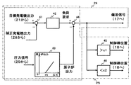
図1において、原子炉1の内部には、炉心2が設置されており炉内の冷却材を沸騰させて蒸気を生成する。原子炉1には、冷却材を循環させる再循環ポンプ3と制御棒4が備えられており、炉心2の出力を調整して発生する蒸気量を制御する。
In FIG. 1, a
原子炉1で生成された蒸気は、蒸気配管と蒸気配管に設けられた加減弁5を通じて高圧タービン6及び低圧タービン7に導かれる。高圧タービン6及び低圧タービン7には発電機8が連結されており、発電機8が発電することで、蒸気のエネルギーを電力に変換している。蒸気配管には、原子炉1の圧力を検出する圧力センサ29が設けられている。発電機8の近傍には、発電機出力を検出する発電機出力センサ23が設けられている。発電機出力センサ23が検出した発電機出力信号と圧力センサ29が検出した原子炉1の圧力信号とは、後述する出力制御装置22に入力される。
Steam generated in the nuclear reactor 1 is guided to the high-pressure turbine 6 and the low-pressure turbine 7 through the steam pipe and the control valve 5 provided in the steam pipe. A
高圧タービン6及び低圧タービン7で仕事をした蒸気は復水器10で図示しない海水との熱交換により凝縮され冷却水となる。冷却水は、低圧給水加熱器11で加熱され、給水ポンプ12で原子炉1内と同程度まで加圧された後、再度、高圧給水加熱器13で加熱された後に原子炉1に給水される。
The steam that has worked in the high-pressure turbine 6 and the low-pressure turbine 7 is condensed in the
また、原子炉1で発生した蒸気は熱効率向上のため、抽気され給水加熱器11、13や湿分分離加熱器9に供給される。図1の例では、高圧給水加熱器13および湿分分離加熱器9への抽気管には抽気弁14および抽気弁15が設置されている。
Further, the steam generated in the nuclear reactor 1 is extracted and supplied to the
本発明の原子力プラントの出力制御装置及び方法の第1の実施の形態において、プラント出力制御装置16は、再循環流量制御装置17と制御棒制御装置18と圧力制御装置19と抽気制御装置20と目標値生成装置21と出力制御装置22とで構成されている。出力制御装置22は、偏差信号出力器24と制御棒位置設定器25と加減弁開度設定器26と抽気量設定器27と補正発電機出力算出器28とを備えている。
In the first embodiment of the power plant output control device and method of the present invention, the plant
再循環流量制御装置17は、再循環ポンプ3へ流量制御指令を出力して、原子炉1の再循環流量を制御するもので、出力制御装置22の偏差信号出力器24から偏差信号を入力する。この偏差信号に応じて再循環流量が制御される。偏差信号が正の場合は再循環流量を増やし、負の場合は再循環流量を減少するよう、比例積分演算を実施する方法や、再循環流量の変化量と発電機出力の変化量との関係をテーブル化しておき、偏差をゼロにするような再循環流量を算出する方法を用いることができる。
The recirculation
制御棒制御装置18は、制御棒4へ挿入または引抜き指令を出力して、制御棒位置を制御するもので、出力制御装置22の制御棒位置設定器25から位置信号を入力する。
The control
圧力制御装置19は、加減弁5へ開度指令を出力して、原子炉1の圧力を設定値に調整するもので、出力制御装置22の加減弁開度設定器26から補正発電機出力に応じた圧力設定値信号を入力する。
The
抽気制御装置20は、抽気弁14へ開度指令を出力して、抽気弁14からの抽気量を設定値となるように調整するもので、出力制御装置22の抽気量設定器27から抽気量信号を入力する。
The
図2を用いて抽気量設定器27の構成を説明する。抽気量設定器27は、減算器31と変換演算器32とを備えている。減算器31は、目標値生成装置21から出力された目標発電機出力と、発電機出力センサ23から出力された発電機出力信号とを入力として、第1の発電機出力偏差信号を演算し、変換演算器32に出力する。変換演算器32は、入力した第1の発電機出力偏差信号を抽気量に変換する変換式が予め設定されていて、抽気量信号を演算し、抽気制御装置20へ出力する。変換演算器32で算出する抽気量は、図2に示すように、入力する偏差信号が設定値a未満のときには、定格抽気量が出力するように設定し、設定値a以上に偏差が増加すれば増加に応じて抽気量を減少させ、設定値aよりも大きい設定値b以上では、抽気量を最小の一定値が出力するように設定している。
The configuration of the extraction
次に、図3を用いて偏差信号出力器24及び制御棒位置設定器25の構成を説明する。偏差信号出力器24は、第1減算器41と制御器42と変換演算器43と第2減算器44とを備えている。制御棒位置設定器25は、これらの演算器41乃至44に加えて第1比較器45と第2比較器46とを備えている。
Next, the configuration of the deviation
第1減算器41は、目標値生成装置21から出力された目標発電機出力と、補正発電機出力算出器28から出力された補正発電機出力信号とを入力として、第2の発電機出力偏差信号を演算し、制御器42に出力する。制御器42は、比例積分演算を行い、負荷要求信号を演算し、第2減算器44へ出力する。
The
変換演算器43は、圧力センサ29が検出した原子炉1の圧力信号を入力し、予め設定された原子炉出力と圧力とのテーブル等に基づき原子炉出力信号を演算し、第2減算器44へ出力する。第2減算器44は上述した負荷要求信号と原子炉出力信号とを入力し、偏差信号を演算し、再循環流量制御装置17へ出力する。
The
制御棒位置設定器25では、第2減算器44の出力信号が第1比較器45と第2比較器46に入力される。第1比較器45は、入力した偏差信号が設定値であるc1よりも大きいときには、制御棒を最小駆動単位だけ引き抜く位置信号を制御棒制御装置18に出力する。第2比較器46は、入力した偏差信号が設定値であるc2よりも小さいときには、制御棒を最小駆動単位だけ挿入する位置信号を制御棒制御装置18に出力する。
In the control rod
次に、図4を用いて補正発電機出力算出器28の構成を説明する。補正発電機出力算出器28は、変換演算器47と減算器48とを備えている。変換演算器47は、抽気量設定器27から抽気量設定値を入力し、予め設定された抽気量と発電機出力変化量とのテーブル等に基づき定格抽気量からの変化による発電機出力への寄与分信号を演算し、減算器48へ出力する。変換演算器47で算出する発電機出力への寄与分信号は、図4に示すように、入力する抽気量設定値が定格のときは、0が出力するように設定し、抽気量設定値が減少すれば減少に応じて発電機出力変化である発電機出力への寄与分信号が増加し、抽気量設定値が0のときに最大値が出力するように設定している。減算器48は、発電機出力センサ23から出力された発電機出力信号と変換演算器47から出力された発電機出力への寄与分信号とを入力として、補正発電機出力信号を演算し、偏差信号出力器24及び制御棒位置設定器25に出力する。
Next, the configuration of the corrected
なお、補正発電機出力の演算は、図4に示した構成以外にも、例えば、圧力センサ29が検出した原子炉圧力信号と変換演算器43を用いて原子炉出力信号を演算し、予め定めた抽気制御を用いない場合の原子炉出力と発電機出力との変換式を利用して算出することもできる。
In addition to the configuration shown in FIG. 4, for example, the calculation of the corrected generator output is performed in advance by calculating the reactor output signal using the reactor pressure signal detected by the
次に、本実施の形態におけるプラント出力制御装置16の動作の概要を説明する。図1において、原子力プラントが一定の発電機出力で運転している際は、原子炉出力も一定出力状態で維持され、再循環流量や制御棒位置は短時間では変化しない。また、加減弁5は原子炉出力に応じた開度で一定に保たれていて、抽気弁14、15は全開(定格流量位置)となっていて、一定量の抽気がなされている。この状態から、運転員または中央給電指令所から目標値生成装置21に対して発電機出力目標値及びその変化率が入力されると、目標値生成装置21は時々刻々の目標発電機出力を出力制御装置22に出力する。
Next, the outline | summary of operation | movement of the plant
出力制御装置22では、抽気量設定器27において図2に示すように、目標発電機出力と発電機出力信号から第1の発電機出力偏差を減算器31で算出し、変換演算器32にて、第1の発電機出力偏差から偏差に応じて予め設定された抽気量に変換演算する。算出された抽気量の信号は、抽気制御装置20へ送出され、抽気弁14,15からの抽気量が設定された値となるようそれぞれの開度が調整される。
In the
同時に、偏差信号出力器24と制御棒位置設定器25において図3に示すように、第2の発電機出力偏差を第1減算器41で算出し、制御器42を介して負荷要求信号が算出される。一方、変換演算器43を介して原子炉出力信号が算出され、第2減算器44において、負荷要求信号と原子炉出力信号の偏差が算出される。この結果、偏差信号が再循環流量制御装置17に送出され、偏差に応じた再循環流量が再循環流量制御装置17で設定される。偏差信号が正の場合は再循環流量を増やし、負の場合は再循環流量を減少するよう、比例積分演算を実施する方法や、再循環流量の変化量と発電機出力の変化量との関係をテーブル化しておき、偏差をゼロにするような再循環流量を算出する方法を用いることができる。
At the same time, as shown in FIG. 3, the deviation
また、偏差信号が設定値c1より大きい場合には制御棒を引き抜き側へ、設定値c2より小さい場合は制御棒を挿入側へ変更した設定位置信号が制御棒制御装置18へ送出される。制御棒制御装置18は、設定された制御棒位置となるよう制御棒4を操作する。
When the deviation signal is larger than the set value c1, the control rod is sent to the control
そして、原子力プラントにおけるこれらの出力制御の間、出力制御装置22の加減弁開度設定器26は、補正発電機出力に応じた圧力設定値を圧力制御装置19に送出しつづける。圧力制御装置19は加減弁5の開度を圧力設定値に調整するので、原子炉1に急峻な圧力変化が生じない。
Then, during these output controls in the nuclear power plant, the adjusting valve
次に、本発明の原子力プラントの出力制御装置及び方法の第1の実施の形態による発電機出力等の時系列変化を図5を用いて説明する。図5は本発明の原子力プラントの出力制御装置及び方法の第1の実施の形態による発電機出力等の時系列変化を示す特性図である。 Next, the time series change of the generator output etc. by 1st Embodiment of the output control apparatus and method of the nuclear power plant of this invention is demonstrated using FIG. FIG. 5 is a characteristic diagram showing time-series changes in generator output and the like according to the first embodiment of the power plant output control apparatus and method of the present invention.
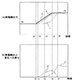
図5において、横軸は時間を示していて、縦軸は、(A)発電機出力、(B)発電機出力変化への寄与分をそれぞれ示している。また、(A)発電機出力における実線の特性aは目標発電機出力を示し、破線の特性bは正味の発電機出力を示す。また、一点鎖線の特性cは補正発電機出力を示す。また、(B)発電機出力変化への寄与分における破線の特性dは抽気量制御による発電機出力への寄与分を示し、一点鎖線で示す特性eは再循環ポンプ及び制御棒制御による発電機出力への寄与分を示している。 In FIG. 5, the horizontal axis indicates time, and the vertical axis indicates (A) generator output and (B) contribution to the generator output change. Further, (A) the solid line characteristic a in the generator output indicates the target generator output, and the broken line characteristic b indicates the net generator output. Also, the dashed line characteristic c indicates the corrected generator output. Further, (B) a broken line characteristic d in the contribution to the generator output change indicates a contribution to the generator output by the extraction amount control, and a characteristic e indicated by a one-dot chain line indicates the generator by the recirculation pump and control rod control. The contribution to the output is shown.
図5(A)で示すように、発電機出力が一定値であるEaで制御されている状態から目標発電機出力を上昇させてEbとして保持した場合における正味発電機出力や寄与分等の各挙動について説明する。 As shown in FIG. 5 (A), each of the net generator output, the contribution, etc. in the case where the target generator output is increased and held as Eb from the state where the generator output is controlled at a constant value Ea. The behavior will be described.
時刻t0において、aで示す目標発電機出力が上昇すると偏差に応じて抽気量が減少し、その分、タービン・発電機に使われる蒸気量が増えるので、発電機出力が増加する。すなわち、図5(B)のdに示すように抽気量制御による発電機出力への寄与分が時刻t1において、ゼロから上昇を開始する。 When the target generator output indicated by a rises at time t0, the amount of extraction decreases according to the deviation, and the amount of steam used for the turbine / generator increases accordingly, so that the generator output increases. That is, as indicated by d in FIG. 5B, the contribution to the generator output by the extraction amount control starts to increase from zero at time t1.
そして、この寄与分だけ図5(A)のbに示す正味の発電機出力が上昇する。この時点で、再循環流量及び制御棒位置は発電機出力を上昇する方向へ操作が開始されているが、eで示す再循環ポンプ及び制御棒制御による発電機出力への寄与分は増加していない。これは、前述したように機械的な動作に伴う遅れ、反応度の投入により核反応が増加するまでの遅れ、増加した核反応により燃料内で発生した熱が冷却材に伝わるまでの遅れ等によるものである。 And the net generator output shown to b of FIG. 5 (A) raises by this contribution. At this point, the recirculation flow rate and control rod position have been started to increase the generator output, but the contribution to the generator output by the recirculation pump and control rod control indicated by e has increased. Absent. As described above, this is due to a delay due to mechanical operation, a delay until the nuclear reaction increases due to the input of reactivity, a delay until the heat generated in the fuel due to the increased nuclear reaction is transmitted to the coolant, etc. Is.
図5(B)の時刻t2において、抽気量制御により正味の発電機出力が上昇すると、第1の発電機出力偏差の増大は抑制され、抽気量制御による寄与分は飽和し始める。その後、数秒から数10秒程度経過した後、再循環ポンプ及び制御棒制御による発電機出力への寄与分が増大し始めると更に偏差が小さくなり、時刻t3においては、抽気量が上昇方向に転じるので、dに示す抽気量制御による発電機出力への寄与分は減少し始める。 When the net generator output is increased by the extraction amount control at time t2 in FIG. 5B, the increase in the first generator output deviation is suppressed, and the contribution due to the extraction amount control starts to be saturated. Thereafter, after a few seconds to several tens of seconds have elapsed, when the contribution to the generator output by the recirculation pump and control rod control starts to increase, the deviation further decreases, and at time t3, the amount of bleed turns upward. Therefore, the contribution to the generator output due to the extraction amount control indicated by d starts to decrease.
そして、時刻t4において、eで示す再循環ポンプ及び制御棒制御による発電機出力への寄与分がaで示す目標発電機出力の増分Ebと等しい値まで増加すると、抽気量は定格流量まで上昇して一定値となり、再循環流量及び制御棒位置はbで示す正味の発電機出力が目標発電機出力を維持する流量及び位置で運転される。cで示す補正発電機出力は、bで示す正味の発電機出力からdで示す抽気量制御による発電機出力への寄与分を減じたものであるので、時刻t4において、正味の発電機出力と一致する。 Then, at time t4, when the contribution to the generator output by the recirculation pump indicated by e and control rod control increases to a value equal to the increment Eb of the target generator output indicated by a, the extraction amount increases to the rated flow rate. The recirculation flow rate and the control rod position are operated at a flow rate and position at which the net generator output indicated by b maintains the target generator output. Since the corrected generator output indicated by c is obtained by subtracting the contribution to the generator output by the extraction amount control indicated by d from the net generator output indicated by b, at time t4, the net generator output and Match.
次に、本発明の原子力プラントの出力制御装置及び方法の第1の実施の形態による出力制御方法について図6を用いて説明する。図6は本発明の原子力プラントの出力制御装置及び方法の第1の実施の形態における処理フローを示すフローチャート図である。 Next, an output control method according to the first embodiment of the output control apparatus and method for a nuclear power plant of the present invention will be described with reference to FIG. FIG. 6 is a flowchart showing a processing flow in the first embodiment of the power plant output control apparatus and method of the present invention.
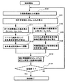
プラント出力制御装置16は、目標発電機出力を算出する(ステップS101)。具体的には、出力制御装置22にて、目標値生成装置21からの発電機出力の目標値と変化率から目標発電機出力Etを算出する。
The plant
プラント出力制御装置16は、第1の発電機出力偏差を算出する(ステップS111)。具体的には、出力制御装置22にて、目標発電機出力Etから発電機出力センサ23の出力値Epを減算して第1の発電機出力偏差ΔE1を算出する。
The plant
プラント出力制御装置16は、抽気量設定値Weを算出する(ステップS112)。具体的には、出力制御装置22にて、第1の発電機出力偏差ΔE1から変換演算器32を介して算出する。
The plant
プラント出力制御装置16は、抽気量を抽気量設定値Weに調整する(ステップS113)。具体的には、出力制御装置22から抽気制御装置20へ抽気量信号を送出し、抽気制御装置20が抽気弁14の開度を調整することで行う。
The plant
(ステップS101)の処理の後に(ステップS111)の処理と同時に、以下の(ステップS121)が行われる。プラント出力制御装置16は、補正発電機出力を算出する(ステップS121)。具体的には、出力制御装置22にて、抽気量設定値から発電機出力変化の変換演算を行い抽気による発電機出力への寄与分ΔEeを算出し、発電機出力センサ23の出力値EpからΔEeを減算して補正発電機出力を算出する。
The following (Step S121) is performed simultaneously with the (Step S111) process after the (Step S101) process. The plant
プラント出力制御装置16は、第2の発電機出力偏差を算出する(ステップS122)。具体的には、出力制御装置22にて、目標発電機出力Etから補正発電機出力であるEp−ΔEeを減算して第2の発電機出力偏差ΔE2を算出する。
The plant
プラント出力制御装置16は、再循環流量及び制御棒位置の設定値を算出する(ステップS123)。具体的には、出力制御装置22にて、第2の発電機出力偏差ΔE2を基にして算出する。
The plant
プラント出力制御装置16は、再循環流量及び制御棒位置を設定値に調整する(ステップS124)。具体的には、出力制御装置22から再循環流量制御装置17と制御棒制御装置18へ、再循環流量信号、制御棒位置信号を送出し、再循環流量制御装置17が再循環ポンプ3を制御し、制御棒制御装置18が制御棒の4の位置を制御する。
The plant
プラント出力制御装置16は、補正発電機出力に応じた開度に加減弁5を調整する(ステップS102)。具体的には、出力制御装置22から圧力制御装置19へ補正発電機出力であるEp−ΔEeの指令を送出し、圧力制御装置19が補正発電機出力に応じた開度に加減弁5を調整する。
The plant
(ステップS102)の処理を実行後、プラント出力制御装置16は、制御が終了したか否かを判断する。制御が終了していない場合には、(ステップS101)へ戻り、それ以外の場合には、制御終了となる。このように、これらのステップを制御が終了するまで繰り返すことにより、所望の制御結果を得ることができる。
After executing the process of (Step S102), the plant
上述したように、本実施の形態によれば、発電機出力の偏差に応じて抽気を絞ることにより、タービン・発電機への蒸気量を増加していち早く目標発電機出力に追従させることができる。また、その際に、原子炉圧力は補正発電機出力に応じて調整されるため、急峻な変化を生じず、原子炉1の出力を安定して追従させることができる。 As described above, according to the present embodiment, the amount of steam to the turbine / generator can be increased to quickly follow the target generator output by restricting the extraction according to the deviation of the generator output. . At that time, since the reactor pressure is adjusted according to the corrected generator output, the output of the reactor 1 can be stably followed without causing a sharp change.
また、本実施の形態によれば、再循環ポンプ3及び制御棒制御により発電機出力が目標値に到達した後は抽気量が定格流量に戻るため、抽気量による制御が数秒から数10秒の初期応答に限定され、抽気量変化にともなうプラント熱効率の低下を最小限に抑制することができる。
Further, according to the present embodiment, after the generator output reaches the target value by the
上述した本発明の原子力プラントの出力制御装置及び方法の第1の実施の形態によれば、発電機出力への短時間での出力変更要求に対して、主蒸気の抽気を制御することにより、素早く追従することが可能となる。また、抽気による制御時間を最小限に抑制することができるので、プラント熱効率の低下を抑制することができる。 According to the first embodiment of the power plant output control apparatus and method of the present invention described above, by controlling the extraction of the main steam in response to the output change request in a short time to the generator output, It is possible to follow quickly. Moreover, since the control time by extraction can be suppressed to the minimum, a decrease in plant thermal efficiency can be suppressed.
以下、本発明の原子力プラントの出力制御装置及び方法の第2の実施の形態を図面を用いて説明する。図7は本発明の原子力プラントの出力制御装置及び方法の第2の実施の形態を構成する抽気量設定器の内容を示す制御ブロック図、図8は本発明の原子力プラントの出力制御装置及び方法の第2の実施の形態による発電機出力等の時系列変化を示す特性図、図9は本発明の原子力プラントの出力制御装置及び方法の第2の実施の形態における処理フローを示すフローチャート図である。図7乃至図9において、図1乃至図6に示す符号と同符号のものは同一部分であるので、その詳細な説明は省略する。 Hereinafter, a second embodiment of an output control apparatus and method for a nuclear power plant according to the present invention will be described with reference to the drawings. FIG. 7 is a control block diagram showing the contents of an extraction amount setting device constituting the second embodiment of the power plant output control device and method of the present invention, and FIG. 8 is the power plant output control device and method of the present invention. FIG. 9 is a characteristic diagram showing time-series changes in generator output and the like according to the second embodiment, and FIG. 9 is a flowchart showing a processing flow in the second embodiment of the power plant output control apparatus and method of the present invention. is there. 7 to 9, the same reference numerals as those shown in FIGS. 1 to 6 are the same parts, and the detailed description thereof is omitted.
本発明の原子力プラントの出力制御装置及び方法の第2の実施の形態において、原子力プラント出力制御装置の全体構成は、大略第1の実施の形態と同じであるが、抽気量設定器27の制御ブロック図とプラント出力制御装置16の処理フローが異なる。
In the second embodiment of the power plant output control apparatus and method of the present invention, the overall configuration of the nuclear power plant output control apparatus is substantially the same as that of the first embodiment, but the control of the extraction
本実施の形態においては、図7に示すように、抽気量設定器27の制御において、第1の発電機出力偏差を減算器31で算出する際に、第2の発電機出力偏差と同様に補正発電機出力信号を用いる。このように、第1の発電機出力偏差の算出に補正発電機出力を用いたので、抽気量制御で抽気が変化し、正味の発電機出力が変化した後も、再循環ポンプ及び制御棒制御による発電機出力への寄与はすぐには増加しないため、第1の発電機出力偏差は減少しない。
In the present embodiment, as shown in FIG. 7, when the first generator output deviation is calculated by the
このため、数秒から数10秒程度経過した後、再循環ポンプ3及び制御棒制御による発電機出力への寄与が増大し始めるまで偏差は減少せず、抽気量制御でより大きな発電機出力の応答性改善が図れる。
For this reason, after several seconds to several tens of seconds, the deviation does not decrease until the contribution to the generator output by the
また、図7の変換演算器32に設定されている特性において、抽気量の減少開始点を決める偏差信号の設定値aについては、制御棒位置設定器25の第1比較器45、第2比較器46の設定値であるc1、c2より大きな値に設定している。これにより、発電機出力偏差が微小な場合は、再循環流量制御及び制御棒制御が優先され、抽気弁14の頻繁な開閉を回避でき、保守作業の増大を防止することができる。
Further, in the characteristics set in the
次に、本実施の形態による発電機出力等の時系列変化を図8を用いて説明する。図5に示す第1の実施の形態と比べて、抽気制御によりbで示す正味の発電機出力が増加した後(時刻t2の後)もdで示す抽気量の寄与分が減少せず、再循環ポンプ及び制御棒制御による発電機出力の増大の前に(時刻t4の前であって時刻t3近傍)目標値付近まで追従することができる。 Next, time series changes such as the generator output according to the present embodiment will be described with reference to FIG. Compared with the first embodiment shown in FIG. 5, the contribution of the extraction amount indicated by d does not decrease even after the net generator output indicated by b is increased by the extraction control (after time t2). Before the generator output is increased by the circulation pump and control rod control (before time t4 and in the vicinity of time t3), it is possible to follow the target value.
次に、本実施の形態による出力制御方法について図9を用いて説明する。本実施の形態における制御方法では、図6に示した第1の実施の形態のフローに対して、ステップS111の処理内容が変更されている。すなわち、ステップS121で算出した補正発電機出力Ep−ΔEeを目標発電機出力Etから減算して第1の発電機出力偏差ΔE1を算出している。その他の手順は図6に示した第1の実施の形態と同一とすることで所望の制御結果を得ることができる。 Next, the output control method according to this embodiment will be described with reference to FIG. In the control method of the present embodiment, the processing content of step S111 is changed with respect to the flow of the first embodiment shown in FIG. That is, the first generator output deviation ΔE1 is calculated by subtracting the corrected generator output Ep−ΔEe calculated in step S121 from the target generator output Et. Other procedures can be the same as those in the first embodiment shown in FIG. 6 to obtain a desired control result.
上述した本発明の原子力プラントの出力制御装置及び方法の第2の実施の形態によれば、第1の実施の形態と同様の効果を得ることができる。 According to the second embodiment of the power plant output control apparatus and method of the present invention described above, the same effects as those of the first embodiment can be obtained.
また、上述した本発明の原子力プラントの出力制御装置及び方法の第2の実施の形態によれば、目標発電機出力に対する追従性を更に向上することができる。加えて、抽気制御を開始する偏差信号の設定値aを、再循環流量制御及び制御棒制御を開始する偏差信号の値よりも大きく設定しているので、抽気弁14の保守作業の頻度を抑制することができる。
Moreover, according to the second embodiment of the power plant output control apparatus and method of the present invention described above, the followability to the target generator output can be further improved. In addition, since the set value a of the deviation signal for starting extraction control is set to be larger than the value of the deviation signal for starting recirculation flow rate control and control rod control, the frequency of maintenance work for the
以下、本発明の原子力プラントの出力制御装置及び方法の第3の実施の形態を図面を用いて説明する。図10は本発明の原子力プラントの出力制御装置及び方法の第3の実施の形態を構成する抽気量設定器の内容を示す制御ブロック図である。図10において、図1乃至図9に示す符号と同符号のものは同一部分であるので、その詳細な説明は省略する。 Hereinafter, a third embodiment of an output control apparatus and method for a nuclear power plant according to the present invention will be described with reference to the drawings. FIG. 10 is a control block diagram showing the contents of the extraction amount setting device constituting the third embodiment of the power plant output control apparatus and method of the present invention. In FIG. 10, the same reference numerals as those shown in FIG. 1 to FIG. 9 are the same parts, and detailed description thereof will be omitted.
本実施の形態において、原子力プラント出力制御装置の全体構成は、大略第1の実施の形態と同じであるが、抽気量設定器27の制御ブロック図が異なる。本実施の形態においては、目標値生成装置21から目標発電機出力信号を入力して変化率を算出する変化率演算器51と偏差ゼロ信号と等しい信号を出力する信号発生器52とを備えている。減算器31の出力は変化率演算器51の第1接点を介して変換演算器32に接続されていて、信号発生器52の出力は変化率演算器51の第2接点を介して変換演算器32に接続されている。
In the present embodiment, the overall configuration of the nuclear power plant output control device is substantially the same as that of the first embodiment, but the control block diagram of the extraction
変化率演算器51は、予め定めた所定の変化率dと算出した目標発電機出力の変化率とを比較し、目標発電機出力の変化率が所定の値dを超過するときは、第1接点のみを閉動作させ、第1の実施の形態と同様に減算器31で算出した偏差信号を変換演算器32に入力する。このことにより、偏差に応じた抽気量が算出され、抽気制御装置20へ送出される。
The
一方、目標発電機出力の変化率が所定の値d以下のときは、第2接点のみを閉動作させ、発電機出力の偏差信号としてゼロ信号を変換演算器32に入力する。このことにより、抽気量設定値は定格値に等しくなるので、抽気制御は実施されない。
On the other hand, when the rate of change of the target generator output is equal to or less than the predetermined value d, only the second contact is closed, and a zero signal is input to the
本実施の形態によれば、万一、再循環ポンプ3及び制御棒4の制御系あるいは駆動系などに不具合が生じて、これらの制御により発電機出力を目標に到達させることができない場合が生じたとしても、目標発電機出力の変化率が十分小さくなった時点で抽気量設定値を定格値とするので、継続的に抽気量を減少させた状態、すなわち、抽気弁14の開度を全開ではない状態で維持することを防止する。この結果、抽気弁14の保守作業の頻度を抑制することができる。
According to this embodiment, in the unlikely event that a malfunction occurs in the control system or drive system of the
上述した本発明の原子力プラントの出力制御装置及び方法の第3の実施の形態によれば、第1の実施の形態と同様の効果を得ることができる。 According to the third embodiment of the power plant output control apparatus and method of the present invention described above, the same effects as those of the first embodiment can be obtained.
また、上述した本発明の原子力プラントの出力制御装置及び方法の第3の実施の形態によれば、抽気弁14の保守作業の頻度を抑制することができる。
Further, according to the third embodiment of the output control device and method for a nuclear power plant of the present invention described above, the frequency of maintenance work of the
以下、本発明の原子力プラントの出力制御装置及び方法の第4の実施の形態を図面を用いて説明する。図11は本発明の原子力プラントの出力制御装置及び方法の第4の実施の形態を備えた原子力プラントを示す全体構成図、図12は本発明の原子力プラントの出力制御装置及び方法の第4の実施の形態を構成する抽気量設定器の内容を示す制御ブロック図である。図11及び図12において、図1乃至図10に示す符号と同符号のものは同一部分であるので、その詳細な説明は省略する。 Hereinafter, a fourth embodiment of an output control apparatus and method for a nuclear power plant according to the present invention will be described with reference to the drawings. FIG. 11 is an overall configuration diagram showing a nuclear power plant equipped with the fourth embodiment of the power plant output control apparatus and method of the present invention, and FIG. 12 shows a fourth power plant control apparatus and method according to the present invention. It is a control block diagram which shows the content of the extraction amount setting device which comprises embodiment. 11 and 12, the same reference numerals as those shown in FIGS. 1 to 10 are the same parts, and detailed description thereof is omitted.
本発明の原子力プラントの出力制御装置及び方法の第4の実施の形態において、原子力プラント出力制御装置16に新たな抽気制御装置61が追加され、抽気弁15を制御する構成とした点が第1の実施の形態と異なる。図11に示すように、抽気制御装置61は、抽気弁15へ開度指令を出力して、抽気弁15からの抽気量を設定値となるように調整するもので、出力制御装置22の抽気量設定器27から抽気量信号を入力する。
In the fourth embodiment of the power plant output control device and method according to the present invention, a new
図12に示すように、本実施の形態における抽気量設定器27は、減算器31の出力であって第1の発電機出力偏差が入力される変換演算器62を備えている。変換演算器62は、入力した第1の発電機出力偏差信号を抽気量に変換する変換式が予め設定されていて、抽気量信号を演算し、抽気制御装置61へ出力する。変換演算器62で算出する抽気量は、図12に示すように、入力する偏差信号が設定値e未満のときには、定格抽気量が出力するように設定し、設定値e以上に偏差が増加すれば増加に応じて抽気量を減少させ、設定値eよりも大きい設定値f以上では、抽気量を最小の一定値が出力するように設定している。
As shown in FIG. 12, the extraction
ここで、変換演算器62の設定値eは、変換演算器32の設定値aよりも小さい値に設定され、同様に、変換演算器62の設定値fは、変換演算器32の設定値bよりも小さい値に設定されている。このことにより、目標発電機出力が変化して第1の発電機出力偏差がゼロではなくなった直後は、抽気制御装置61が抽気弁15を制御開始する。そして、発電機出力偏差がaに到達したときに初めて抽気制御装置20が抽気弁14を制御開始する。
Here, the set value e of the
本実施の形態によれば、この実施例によれば、目標発電機出力の変化率があまり大きくない場合、先に制御を開始する抽気制御装置61及び抽気弁15により、正味の発電機出力が増加して発電機出力偏差が抑制されるので、抽気制御装置20及び抽気弁14の制御の動作を抑制することができる。すなわち、抽気弁毎に優先順位を与えることができるので、頻繁に開閉することが望ましくない抽気弁の動作を抑制することができる。なお、本実施の形態では、2つの抽気弁の場合を例に説明したが、さらに多数の抽気弁を用いることも可能である。
According to this embodiment, according to this example, when the rate of change of the target generator output is not so large, the
上述した本発明の原子力プラントの出力制御装置及び方法の第4の実施の形態によれば、第1の実施の形態と同様の効果を得ることができる。 According to the above-described fourth embodiment of the power plant output control apparatus and method of the present invention, the same effects as those of the first embodiment can be obtained.
また、上述した本発明の原子力プラントの出力制御装置及び方法の第4の実施の形態によれば、抽気弁14の保守作業の頻度を抑制することができる。
Further, according to the fourth embodiment of the power plant output control apparatus and method of the present invention described above, the frequency of maintenance work of the
以下、本発明の原子力プラントの出力制御装置及び方法の第5の実施の形態を図面を用いて説明する。図13は本発明の原子力プラントの出力制御装置及び方法の第5の実施の形態を備えた原子力プラントを示す全体構成図、図14は本発明の原子力プラントの出力制御装置及び方法の第5の実施の形態を構成する抽気量設定器の内容を示す制御ブロック図である。図13及び図14において、図1乃至図12に示す符号と同符号のものは同一部分であるので、その詳細な説明は省略する。 Hereinafter, a fifth embodiment of an output control apparatus and method for a nuclear power plant according to the present invention will be described with reference to the drawings. FIG. 13 is an overall configuration diagram showing a nuclear power plant equipped with a fifth embodiment of the power plant output control apparatus and method of the present invention, and FIG. 14 shows a fifth power plant control apparatus and method according to the present invention. It is a control block diagram which shows the content of the extraction amount setting device which comprises embodiment. In FIG. 13 and FIG. 14, the same reference numerals as those shown in FIG. 1 to FIG.
本発明の原子力プラントの出力制御装置及び方法の第5の実施の形態において、原子力プラント出力制御装置16に新たな給水制御装置63が追加され、給水ポンプ12の給水量を制御する構成とした点が第1の実施の形態と異なる。図13に示すように、給水制御装置63は、給水ポンプ12へ給水流量指令を出力して、原子炉1の水位を設定値となるように調整するもので、出力制御装置22の抽気量設定器27から水位設定信号を入力する。
In the fifth embodiment of the power plant output control device and method of the present invention, a new water
図14に示すように、本実施の形態における抽気量設定器27は、変換演算器32の出力であって抽気量信号が入力される変換演算器64を備えている。変換演算器64は、入力した抽気量信号を原子炉水位設定値に変換する変換式が予め設定されていて、水位設定信号を演算し、給水制御装置63へ出力する。変換演算器64で算出する水位設定値は、図14に示すように、入力する抽気量信号が設定値g未満のときには、水位設定を低く設定し、設定値g以上に抽気量信号が増加すれば増加に応じて水位設定値を増加させ、設定値gよりも大きい設定値h以上では、水位設定値を定格値が出力するように設定している。
As shown in FIG. 14, the extraction
これにより、抽気量が大きいときには水位設定を高くし、抽気量が小さいときには水位設定を低くする。この結果、抽気量が小さいときに給水流量を減少させる。給水加熱器13へ供給する抽気を減少させると、供給される熱量が減少するため給水温度が低下する。給水温度が低下すると、冷却水の炉心2入口でのサブクーリングが増大し、ボイド割合が減少して出力が増加する。出力が増加する効果は、発電機出力を増加する場合には望ましい変化ではあるが、一定以上の変化をもたらす場合は抑制することが必要となる。
Accordingly, the water level setting is increased when the extraction amount is large, and the water level setting is decreased when the extraction amount is small. As a result, when the extraction amount is small, the feed water flow rate is decreased. When the bleed air supplied to the
本実施の形態のプラント出力制御装置16では、抽気量を減少させたときの給水温度の低下を抑制するため、抽気量の減少とともに、給水流量を減少させることができる。これにより、急峻な原子炉1の出力変化を抑制してより安定した原子炉1の出力制御が可能となる。
In the plant
上述した本発明の原子力プラントの出力制御装置及び方法の第5の実施の形態によれば、第1の実施の形態と同様の効果を得ることができる。 According to the fifth embodiment of the power plant output control apparatus and method of the present invention described above, the same effects as those of the first embodiment can be obtained.
また、上述した本発明の原子力プラントの出力制御装置及び方法の第5の実施の形態によれば、抽気量を減少させたときの給水温度の低下を抑制するため、抽気量の減少とともに、給水流量を減少させることができる。これにより、急峻な原子炉1の出力変化を抑制してより安定した原子炉1の出力制御が可能となる。 Further, according to the fifth embodiment of the output control device and method for a nuclear power plant of the present invention described above, in order to suppress a decrease in the feed water temperature when the bleed amount is reduced, the water supply is reduced along with the decrease in the bleed amount. The flow rate can be reduced. Thereby, it is possible to control the output of the nuclear reactor 1 more stably by suppressing a sharp change in the output of the nuclear reactor 1.
なお、本発明は上述した第1乃至第5の実施の形態に限られるものではなく、様々な変形例が含まれる。上記した実施形態は本発明をわかり易く説明するために詳細に説明したものであり、必ずしも説明した全ての構成を備えるものに限定されるものではない。例えば、ある実施形態の構成の一部を他の実施の形態の構成に置き換えることが可能であり、また、ある実施形態の構成に他の実施の形態の構成を加えることも可能である。また、各実施形態の構成の一部について、他の構成の追加、削除、置換をすることも可能である。 The present invention is not limited to the first to fifth embodiments described above, and includes various modifications. The above-described embodiment has been described in detail for easy understanding of the present invention, and is not necessarily limited to the one having all the configurations described. For example, part of the configuration of one embodiment can be replaced with the configuration of another embodiment, and the configuration of another embodiment can be added to the configuration of one embodiment. Moreover, it is also possible to add, delete, or replace another configuration for a part of the configuration of each embodiment.
1:原子炉、2:炉心、3:再循環ポンプ、4:制御棒、5:加減弁、6:高圧タービン、7:低圧タービン、8:発電機、9:湿分分離加熱器、10:復水器、11:低圧給水加熱器、12:給水ポンプ、13:高圧給水加熱器、14:抽気弁、15:抽気弁、16:プラント出力制御装置、17:再循環流量制御装置、18:制御棒制御装置、19:圧力制御装置、20:抽気制御装置、21:目標値生成装置、22:出力制御装置、23:発電機出力センサ、24:偏差信号出力器、25:制御棒位置設定器、26:加減弁開度設定器、27:抽気量設定器、28:補正発電機出力算出器、29:圧力センサ、31:減算器、32:変換演算器、41:第1減算器、42:制御器、43:変換演算器、44:第2減算器、45:第1比較器、46:第2比較器、47:変換演算器、48:減算器、51:変化率演算器、61:抽気制御装置、62:変換演算器、63:給水制御装置、64:変換演算器 1: nuclear reactor, 2: core, 3: recirculation pump, 4: control rod, 5: control valve, 6: high pressure turbine, 7: low pressure turbine, 8: generator, 9: moisture separator heater, 10: Condenser, 11: Low pressure feed water heater, 12: Feed water pump, 13: High pressure feed water heater, 14: Extraction valve, 15: Extraction valve, 16: Plant output control device, 17: Recirculation flow control device, 18: Control rod control device, 19: pressure control device, 20: extraction control device, 21: target value generation device, 22: output control device, 23: generator output sensor, 24: deviation signal output device, 25: control rod position setting 26: Acceleration / deceleration valve opening setting device, 27: Extraction amount setting device, 28: Corrected generator output calculator, 29: Pressure sensor, 31: Subtractor, 32: Conversion calculator, 41: First subtractor, 42: Controller, 43: Conversion calculator, 44: Second subtractor, 45: First ratio Vessels, 46: second comparator, 47: transform operator, 48: subtractor, 51: change rate arithmetic unit, 61: extraction control unit, 62: transform operator, 63: water supply control apparatus, 64: transform operator
Claims (10)
前記発電機の出力目標値を生成する目標値生成装置と、前記発電機の実出力を計測するセンサと、
前記発電機の出力目標値と前記発電機の実出力との差である第1の発電機出力偏差信号に基づき前記蒸気の抽気量を設定する抽気制御装置と、
前記抽気制御装置の設定値に一致するよう前記抽気弁を駆動する抽気弁制御装置と、
前記発電機の実出力から前記抽気制御装置の抽気量の制御による前記発電機の出力への寄与分を減算した補正発電機出力と、前記発電機の出力目標値と前記補正発電機出力との差である第2の発電機出力偏差信号を出力する出力制御装置と、
前記出力制御装置からの第2の発電機出力偏差信号に応じて、前記再循環ポンプの再循環流量を調整する再循環流量制御装置と、
前記出力制御装置からの第2の発電機出力偏差信号に応じて、前記制御棒の位置を変更する制御棒制御装置とを備え、
前記抽気制御装置で設定した前記蒸気の抽気量は、予め定めた第1閾値より前記第1の発電機出力偏差信号が大きいときに、定格抽気量を減少させるように設定され、
前記出力制御装置で設定した前記制御棒の位置を変更する信号の値は、予め定めた第2閾値より前記第2の発電機出力偏差信号が大きいときに、前記制御棒の位置を変更するように設定され、
前記第1閾値を前記第2閾値よりも大きく設定した
ことを特徴とする原子力プラントの出力制御装置。 Driven by a nuclear reactor, a recirculation pump for circulating coolant in the nuclear reactor, a control rod, a regulating valve for adjusting the flow rate of steam generated in the nuclear reactor, and steam that has passed through the regulating valve A turbine, a generator driven by the turbine to generate electric power, and a bleed valve installed between the control valve and the turbine to supply a part of the steam to other equipment;
A target value generating device for generating an output target value of the generator; a sensor for measuring an actual output of the generator;
An extraction control device that sets the extraction amount of the steam based on a first generator output deviation signal that is a difference between an output target value of the generator and an actual output of the generator;
A bleed valve control device that drives the bleed valve to match a set value of the bleed control device;
The corrected generator output obtained by subtracting the contribution to the generator output by controlling the amount of extraction of the extraction control device from the actual output of the generator, the output target value of the generator, and the corrected generator output An output control device for outputting a second generator output deviation signal which is a difference;
A recirculation flow rate control device that adjusts a recirculation flow rate of the recirculation pump according to a second generator output deviation signal from the output control device;
A control rod control device that changes the position of the control rod in response to a second generator output deviation signal from the output control device ;
The steam extraction amount set by the extraction control device is set to decrease the rated extraction amount when the first generator output deviation signal is larger than a predetermined first threshold,
The value of the signal for changing the position of the control rod set by the output control device is such that the position of the control rod is changed when the second generator output deviation signal is larger than a predetermined second threshold value. Set to
An output control apparatus for a nuclear power plant, wherein the first threshold value is set larger than the second threshold value .
前記抽気制御装置は、前記第1の発電機出力偏差信号として、前記第2の発電機出力偏差信号で算出された値と同一の値を使用して前記蒸気の抽気量を設定する
ことを特徴とする原子力プラントの出力制御装置。 In the nuclear power plant output control device according to claim 1,
The extraction control device sets the extraction amount of the steam using the same value as the value calculated by the second generator output deviation signal as the first generator output deviation signal. An output control device for a nuclear power plant.
前記抽気制御装置は、前記発電機の出力目標値の変化率を演算する変化率演算器を備え、
前記発電機の出力目標値の変化率が予め定めた設定値未満の場合には、設定する抽気量を定格抽気量と同一とし、
前記発電機の出力目標値の変化率が予め定めた設定値以上のときのみ前記第1の発電機出力偏差信号に基づき抽気量を設定する
ことを特徴とする原子力プラントの出力制御装置。 In the nuclear power plant output control device according to claim 1 or 2 ,
The extraction control device includes a change rate calculator that calculates a change rate of an output target value of the generator,
When the rate of change of the output target value of the generator is less than a preset value, the extraction amount to be set is the same as the rated extraction amount,
An output control device for a nuclear power plant, wherein the extraction amount is set based on the first generator output deviation signal only when the rate of change of the output target value of the generator is not less than a predetermined set value.
前記抽気弁を複数個備え、
前記抽気制御装置は、前記第1の発電機出力偏差信号に基づき前記蒸気の抽気量を複数の前記抽気弁のそれぞれに設定し、
設定された抽気量において、定格抽気量から変化を開始する前記第1の発電機出力偏差信号の値を抽気弁毎に異なるように設定した
ことを特徴とする原子力プラントの出力制御装置。 In the nuclear power plant output control device according to any one of claims 1 to 3 ,
A plurality of the bleed valves;
The extraction control device sets the extraction amount of the steam to each of the plurality of extraction valves based on the first generator output deviation signal,
An output control device for a nuclear power plant, wherein the value of the first generator output deviation signal that starts changing from the rated bleed amount is set to be different for each bleed valve in the set bleed amount.
前記原子炉へ冷却材を給水する給水ポンプと、前記給水ポンプの給水流量を制御する給水制御装置と、前記原子炉への給水を抽気により加熱する給水加熱器とを備え、
前記出力制御装置は、前記抽気制御装置が設定した前記蒸気の抽気量に基づいて前記給水制御装置に水位設定値を送信し、前記給水制御装置は前記水位設定値に基づいて前記給水ポンプの給水流量を調整する
ことを特徴とする原子力プラントの出力制御装置。 In the nuclear power plant output control apparatus according to any one of claims 1 to 4 ,
A feed water pump for feeding coolant to the nuclear reactor, a feed water control device for controlling the feed water flow rate of the feed water pump, and a feed water heater for heating the feed water to the reactor by extraction,
The output control device transmits a water level set value to the water supply control device based on the steam extraction amount set by the extraction control device, and the water supply control device supplies water to the water supply pump based on the water level set value. An output control device for a nuclear power plant characterized by adjusting a flow rate.
前記出力制御装置は、前記発電機の出力目標値と、前記発電機の実出力とから、第1の発電機出力偏差信号を算出し、前記第1の発電機出力偏差信号に基づき、蒸気の一部を前記他の設備へ供給する前記抽気弁の抽気量を調整する第1のプロセスと、
前記発電機の実出力から前記抽気弁の抽気量の制御による前記発電機の出力への寄与分を減算した補正発電機出力を算出し、前記発電機の出力目標値と前記補正発電機出力から第2の発電機出力偏差信号を算出し、前記第2の発電機出力偏差信号に基づき前記再循環ポンプの再循環流量及び前記制御棒の位置を調整する第2のプロセスとを備え、
前記第1のプロセスと前記第2のプロセスとを並行して実施しており、
前記第1のプロセスにおいて、前記蒸気の抽気量は、予め定めた第1閾値より前記第1の発電機出力偏差信号が大きいときに、定格抽気量を減少させるように設定され、
前記第2のプロセスにおいて、前記制御棒の位置を変更する信号の値は、予め定めた第2閾値より前記第2の発電機出力偏差信号が大きいときに、前記制御棒の位置を変更するように設定され、
前記第1閾値を前記第2閾値よりも大きく設定した
ことを特徴とする原子力プラントの出力制御方法。 A reactor, an adjusting valve for adjusting a flow rate of steam generated in the reactor, a turbine driven by steam passing through the adjusting valve, a generator driven by the turbine to generate electric power, and the adjusting A bleed valve installed between the valve and the turbine and capable of supplying a part of the steam to other equipment, a recirculation pump for circulating the coolant, a control rod, and an output control device An output control method for a nuclear power plant,
The output control device calculates a first generator output deviation signal from the output target value of the generator and the actual output of the generator, and based on the first generator output deviation signal, A first process for adjusting a bleed amount of the bleed valve for supplying a part to the other equipment;
A corrected generator output obtained by subtracting a contribution to the output of the generator by controlling the extraction amount of the extraction valve from the actual output of the generator is calculated, and from the output target value of the generator and the corrected generator output Calculating a second generator output deviation signal, and adjusting a recirculation flow rate of the recirculation pump and a position of the control rod based on the second generator output deviation signal,
Performing the first process and the second process in parallel ;
In the first process, the steam extraction amount is set so as to decrease the rated extraction amount when the first generator output deviation signal is larger than a predetermined first threshold value.
In the second process, the value of the signal for changing the position of the control rod is such that the position of the control rod is changed when the second generator output deviation signal is larger than a predetermined second threshold value. Set to
An output control method for a nuclear power plant, wherein the first threshold value is set larger than the second threshold value .
前記第1のプロセスは、前記第1の発電機出力偏差信号として、前記第2の発電機出力偏差信号で算出された値と同一の値を使用して前記蒸気の抽気量を調整する
ことを特徴とする原子力プラントの出力制御方法。 In the nuclear power plant output control method according to claim 6 ,
The first process uses the same value as the value calculated with the second generator output deviation signal as the first generator output deviation signal to adjust the amount of steam extracted. A nuclear power plant output control method.
前記出力制御装置は、前記発電機の出力目標値の変化率を演算する変化率演算器を備え、
前記第1のプロセスにおいて、前記発電機の出力目標値の変化率が予め定めた設定値未満の場合には、設定する抽気量を定格抽気量と同一とし、
前記発電機の出力目標値の変化率が予め定めた設定値以上のときのみ前記第1の発電機出力偏差信号に基づき抽気量を調整する
ことを特徴とする原子力プラントの出力制御方法。 In the nuclear power plant output control method according to claim 6 or 7 ,
The output control device includes a change rate calculator that calculates a change rate of an output target value of the generator,
In the first process, when the rate of change of the output target value of the generator is less than a predetermined set value, the extraction amount to be set is the same as the rated extraction amount,
An output control method for a nuclear power plant, characterized in that the extraction amount is adjusted based on the first generator output deviation signal only when the rate of change of the output target value of the generator is equal to or greater than a predetermined set value.
前記抽気弁は複数個を備え、
前記第1のプロセスは、前記発電機の出力目標値と、前記発電機の実出力とから、第1の発電機出力偏差信号を算出し、前記第1の発電機出力偏差信号に基づき、蒸気の一部を他の設備へ供給する複数の前記抽気弁の抽気量を調整し、
設定された抽気量において、定格抽気量から変化を開始する前記第1の発電機出力偏差信号の値を抽気弁毎に異なるように設定した
ことを特徴とする原子力プラントの出力制御方法。 In the nuclear power plant output control method according to any one of claims 6 to 8 ,
The bleed valve has a plurality,
The first process calculates a first generator output deviation signal from the output target value of the generator and the actual output of the generator, and based on the first generator output deviation signal, Adjusting the extraction amount of the plurality of extraction valves for supplying a part of the
An output control method for a nuclear power plant characterized in that, in the set extraction amount, the value of the first generator output deviation signal that starts changing from the rated extraction amount is set to be different for each extraction valve.
前記原子力プラントは、前記原子炉へ冷却材を給水する給水ポンプと、前記給水ポンプの給水流量を制御する給水制御装置と、前記原子炉への給水を抽気により加熱する給水加熱器とを備え、
前記出力制御装置は、前記給水加熱器への抽気量に基づき、前記原子炉への給水流量を調整する第3のプロセスを備え、
前記第1のプロセスと前記第2のプロセスと前記第3のプロセスとを並行して実施する
ことを特徴とする原子力プラントの出力制御方法。 In the nuclear power plant output control method according to any one of claims 6 to 9,
The nuclear power plant includes a feed water pump that feeds coolant to the reactor, a feed water control device that controls a feed water flow rate of the feed water pump, and a feed water heater that heats feed water to the reactor by extraction .
The output control device, based on the extraction of Previous Stories feed water heater, comprises a third process for adjusting the feedwater flow rate to the reactor,
The nuclear power plant output control method, wherein the first process, the second process, and the third process are performed in parallel.
Priority Applications (1)
| Application Number | Priority Date | Filing Date | Title |
|---|---|---|---|
| JP2016083756A JP6608324B2 (en) | 2016-04-19 | 2016-04-19 | Power plant output control apparatus and method |
Applications Claiming Priority (1)
| Application Number | Priority Date | Filing Date | Title |
|---|---|---|---|
| JP2016083756A JP6608324B2 (en) | 2016-04-19 | 2016-04-19 | Power plant output control apparatus and method |
Publications (3)
| Publication Number | Publication Date |
|---|---|
| JP2017194312A JP2017194312A (en) | 2017-10-26 |
| JP2017194312A5 JP2017194312A5 (en) | 2019-02-14 |
| JP6608324B2 true JP6608324B2 (en) | 2019-11-20 |
Family
ID=60155462
Family Applications (1)
| Application Number | Title | Priority Date | Filing Date |
|---|---|---|---|
| JP2016083756A Active JP6608324B2 (en) | 2016-04-19 | 2016-04-19 | Power plant output control apparatus and method |
Country Status (1)
| Country | Link |
|---|---|
| JP (1) | JP6608324B2 (en) |
Cited By (1)
| Publication number | Priority date | Publication date | Assignee | Title |
|---|---|---|---|---|
| WO2022216336A3 (en) * | 2021-01-18 | 2022-12-01 | Renewable Energy Aggregators Inc. | Hardened solar energy collector system |
Families Citing this family (2)
| Publication number | Priority date | Publication date | Assignee | Title |
|---|---|---|---|---|
| JP6865186B2 (en) * | 2018-02-28 | 2021-04-28 | 日立Geニュークリア・エナジー株式会社 | Load tracking device and nuclear power plant with it |
| CN110155296A (en) * | 2019-04-03 | 2019-08-23 | 中国船舶重工集团公司第七一九研究所 | Ocean nuclear power platform auxiliary steam converting system |
Family Cites Families (12)
| Publication number | Priority date | Publication date | Assignee | Title |
|---|---|---|---|---|
| US4707324A (en) * | 1984-12-27 | 1987-11-17 | Westinghouse Electric Corp. | Controlling the response of a pressurized water reactor to rapid fluctuations in load |
| JP2559377B2 (en) * | 1986-10-03 | 1996-12-04 | 株式会社日立製作所 | Controller for steam generation plant |
| JPS63204003A (en) * | 1987-02-20 | 1988-08-23 | 株式会社日立製作所 | Steam generation plant output controller |
| JPH01248098A (en) * | 1988-03-30 | 1989-10-03 | Hitachi Ltd | Operating device for small and short ranged load following of boiling water nuclear reactor |
| JPH04278499A (en) * | 1991-03-07 | 1992-10-05 | Hitachi Ltd | Output controlling device of nuclear power plant |
| JP2902217B2 (en) * | 1992-07-13 | 1999-06-07 | 株式会社日立製作所 | Output control method and apparatus for nuclear power plant |
| JPH09304586A (en) * | 1996-05-20 | 1997-11-28 | Toshiba Corp | Boiling water nuclear power plant |
| JP3362603B2 (en) * | 1996-07-15 | 2003-01-07 | 株式会社日立製作所 | Reactor power control device |
| JP2000111003A (en) * | 1998-10-06 | 2000-04-18 | Ishikawajima Harima Heavy Ind Co Ltd | Control method of extraction fluctuation boiler |
| JP2008128881A (en) * | 2006-11-22 | 2008-06-05 | Hitachi-Ge Nuclear Energy Ltd | Operation method of nuclear power plant |
| US20080317191A1 (en) * | 2007-06-20 | 2008-12-25 | Masao Chaki | Operating method of nuclear reactor and nuclear power generation plant |
| KR20150083374A (en) * | 2014-01-09 | 2015-07-17 | 두산중공업 주식회사 | Apparatus and method for reactor power control of steam turbine power generation system |
-
2016
- 2016-04-19 JP JP2016083756A patent/JP6608324B2/en active Active
Cited By (1)
| Publication number | Priority date | Publication date | Assignee | Title |
|---|---|---|---|---|
| WO2022216336A3 (en) * | 2021-01-18 | 2022-12-01 | Renewable Energy Aggregators Inc. | Hardened solar energy collector system |
Also Published As
| Publication number | Publication date |
|---|---|
| JP2017194312A (en) | 2017-10-26 |
Similar Documents
| Publication | Publication Date | Title |
|---|---|---|
| CN101488022B (en) | Advanced control method for thermal power unit boiler turbine coordination system | |
| CN109491337A (en) | A kind of fired power generating unit coordinated control system and its control method for coordinating | |
| JP6608324B2 (en) | Power plant output control apparatus and method | |
| JP5108644B2 (en) | Boiler control device and boiler control method | |
| CN109378833B (en) | Method for realizing rapid frequency modulation of unit by controlling steam extraction amount of steam turbine | |
| CN112648029A (en) | Coordinated control optimization method for deep peak regulation working condition of thermal power plant | |
| JP2015124711A (en) | Control device and activation method | |
| KR101093032B1 (en) | Controlling method for fast and linear load control by using compensating models and optimization for turbine and boiler response delays in power plants | |
| JP5665688B2 (en) | Steam temperature control device and steam temperature control method | |
| CN110925732A (en) | Agriculture and forestry biomass water-cooling vibration grate boiler combined heat and power generation unit small-capacity hot well and deaerator water level combined control strategy and device | |
| JP2013181679A (en) | Power generation system, and steam temperature control method therefor | |
| JP2017194312A5 (en) | ||
| EP2867735A1 (en) | A method for optimization of control and fault analysis in a thermal power plant | |
| JP4656029B2 (en) | System frequency stabilization apparatus and method | |
| CN104566352A (en) | Circulating fluidized bed boiler primary air fan control method and system adopting instruction regulator | |
| CN113050411A (en) | Steam turbine main control auxiliary pressure regulating control system and method during deep peak regulation | |
| CN110865536A (en) | Primary frequency modulation optimization control method, system and medium for thermal power generating unit | |
| JP6543175B2 (en) | Control device and control method of control valve | |
| JP6775070B1 (en) | Power plant control device, power plant, and power plant control method | |
| CN112799447B (en) | Control method of high-pressure heater | |
| CN210323801U (en) | Load automatic control system based on closed-loop negative feedback control | |
| CN113091043B (en) | Method for automatically controlling water level of steam drum of waste heat boiler in whole process | |
| CN214891078U (en) | Automatic fuel quantity control system of thermal power generating unit | |
| CN116816466A (en) | Main steam temperature optimization adjustment method for gas-steam combined cycle unit | |
| CN116951535A (en) | Pressurized water reactor nuclear power cogeneration control method and system |
Legal Events
| Date | Code | Title | Description |
|---|---|---|---|
| A521 | Written amendment |
Free format text: JAPANESE INTERMEDIATE CODE: A523 Effective date: 20181226 |
|
| A621 | Written request for application examination |
Free format text: JAPANESE INTERMEDIATE CODE: A621 Effective date: 20181226 |
|
| A131 | Notification of reasons for refusal |
Free format text: JAPANESE INTERMEDIATE CODE: A131 Effective date: 20190903 |
|
| A977 | Report on retrieval |
Free format text: JAPANESE INTERMEDIATE CODE: A971007 Effective date: 20190830 |
|
| A521 | Written amendment |
Free format text: JAPANESE INTERMEDIATE CODE: A523 Effective date: 20190917 |
|
| TRDD | Decision of grant or rejection written | ||
| A01 | Written decision to grant a patent or to grant a registration (utility model) |
Free format text: JAPANESE INTERMEDIATE CODE: A01 Effective date: 20191008 |
|
| A61 | First payment of annual fees (during grant procedure) |
Free format text: JAPANESE INTERMEDIATE CODE: A61 Effective date: 20191023 |
|
| R150 | Certificate of patent or registration of utility model |
Ref document number: 6608324 Country of ref document: JP Free format text: JAPANESE INTERMEDIATE CODE: R150 |