JP6607222B2 - Connection auxiliary member and grommet - Google Patents
Connection auxiliary member and grommet Download PDFInfo
- Publication number
- JP6607222B2 JP6607222B2 JP2017063676A JP2017063676A JP6607222B2 JP 6607222 B2 JP6607222 B2 JP 6607222B2 JP 2017063676 A JP2017063676 A JP 2017063676A JP 2017063676 A JP2017063676 A JP 2017063676A JP 6607222 B2 JP6607222 B2 JP 6607222B2
- Authority
- JP
- Japan
- Prior art keywords
- grommet
- connector
- connectors
- male
- bodies
- Prior art date
- Legal status (The legal status is an assumption and is not a legal conclusion. Google has not performed a legal analysis and makes no representation as to the accuracy of the status listed.)
- Active
Links
- 230000008878 coupling Effects 0.000 claims 1
- 238000010168 coupling process Methods 0.000 claims 1
- 238000005859 coupling reaction Methods 0.000 claims 1
- 239000002184 metal Substances 0.000 description 7
- 238000000034 method Methods 0.000 description 6
- 239000000463 material Substances 0.000 description 4
- 238000003780 insertion Methods 0.000 description 2
- 230000037431 insertion Effects 0.000 description 2
- 238000000465 moulding Methods 0.000 description 2
- 238000004026 adhesive bonding Methods 0.000 description 1
- 230000006835 compression Effects 0.000 description 1
- 238000007906 compression Methods 0.000 description 1
- 239000004020 conductor Substances 0.000 description 1
- 230000008602 contraction Effects 0.000 description 1
- 230000005489 elastic deformation Effects 0.000 description 1
- 238000000605 extraction Methods 0.000 description 1
- 238000004519 manufacturing process Methods 0.000 description 1
- 230000013011 mating Effects 0.000 description 1
- 230000002093 peripheral effect Effects 0.000 description 1
- 230000009466 transformation Effects 0.000 description 1
Images

Landscapes
- Insertion, Bundling And Securing Of Wires For Electric Apparatuses (AREA)
- Details Of Connecting Devices For Male And Female Coupling (AREA)
- Coupling Device And Connection With Printed Circuit (AREA)
- Insulating Bodies (AREA)
Description
本発明は、接続補助部材、LANケーブル、及びグロメットに関する。 The present invention relates to a connection auxiliary member, a LAN cable, and a grommet.
近年のサーバ、特に高密度化サーバでは、サーバのリア部に多数のLAN(Local Area Network)ケーブルが接続される傾向がある。このため、サーバ内部のCPU(Central Processing Unit)、メモリ、PCI(Peripheral Component Interconnect)カードの交換或いは増設等に際し、サーバをラックから下して作業を行なおうとすると、作業前に、サーバに繋がっている多数本のLANケーブルを全て取り外し、作業終了後、これら多数本のLANケーブルを作業前の状態に復旧すべく、正確な位置に再接続する必要がある。 In recent servers, particularly high-density servers, a large number of LAN (Local Area Network) cables tend to be connected to the rear part of the server. For this reason, when replacing or adding a CPU (Central Processing Unit), memory, or PCI (Peripheral Component Interconnect) card inside the server, if the server is removed from the rack and the work is performed, the server is connected to the server before the work. It is necessary to remove all the many LAN cables, and after the work is completed, to reconnect these many LAN cables to an accurate position in order to restore the state before the work.
このLANケーブル、あるいはLANケーブル以外の種々のケーブル、あるいはこれらのケーブルの接続に用いられるコネクタを備えたローゼットに関する技術として、下記の特許文献1〜5に記載されたものがある。
特許文献1には、複数のコネクタが接続されるローゼットが開示されている。
特許文献2には、単独のコネクタを筐体に弾性体を用いて支持する技術が開示されている。
特許文献3には、複数のコネクタを互いに弾性体によって連結する技術が開示されている。
特許文献4には、LANケーブルのプラグにグロメット本体を取り付け、このグロメット本体を介して筐体に固定する構造が開示されている。
特許文献5には、いわゆる栓刃を複数対備えたプラグの各対の抜刃の間隔を変更する技術に関するもので、各対の抜刃の間隔がコンセントの各アウトレットの間隔に応じて変更される構造が開示されている。
As a technique related to this LAN cable, various cables other than the LAN cable, or a rosette provided with a connector used to connect these cables, there are those described in Patent Documents 1 to 5 below.
Patent Document 1 discloses a rosette to which a plurality of connectors are connected.
しかしながら、特許文献1に記載されたローゼットは、複数のコネクタが設けられてはいるものの、これらのコネクタへの誤接続を防止する技術を開示するものではない。
また特許文献2に記載されたコネクタには、複数のコネクタの誤接続を防止するための配慮がなされていなかった。
また特許文献3に記載されたコネクタは、単に弾性体によって連結されているに過ぎず、誤接続を防止するための配慮がなされていなかった。
However, although the rosette described in Patent Document 1 is provided with a plurality of connectors, it does not disclose a technique for preventing erroneous connection to these connectors.
Further, the connector described in
Further, the connector described in
また特許文献4に記載されたLANケーブル固定構造にあっても。複数のコネクタの誤接続を防止するための配慮がなされていなかった。
さらに特許文献5に記載された技術にあっても、プラグの配列を変更することはできない。
Even in the LAN cable fixing structure described in
Furthermore, even with the technique described in
この発明は、上記背景技術に鑑みてなされたもので、複数のケーブルをローゼットに接続する作業をローゼット側のコネクタの相互間隔にかかわらず、その相違に対応して容易に行うことができる接続補助部材、LANケーブル、及びグロメットを提供することを目的とする。 The present invention has been made in view of the above-described background art, and it is possible to easily perform the operation of connecting a plurality of cables to the rosette in accordance with the difference regardless of the mutual spacing of the connectors on the rosette side. An object is to provide a member, a LAN cable, and a grommet.
上記課題を解決するために、この発明は以下の手段を提案している。
本発明の第一の態様にかかる接続補助部材は、複数の雌雄何れか一方のコネクタと、該一方のコネクタに対応する複数の雌雄何れか他方のコネクタと、これら雌雄のコネクタの少なくとも一方を収容する収容部と、を備え、前記雌雄いずれか一方のコネクタは、互いの間隔を変更可能に連結されたことを特徴とする。
In order to solve the above problems, the present invention proposes the following means.
The connection assisting member according to the first aspect of the present invention accommodates one of a plurality of male and female connectors, a plurality of male and female connectors corresponding to the one connector, and at least one of these male and female connectors. And either one of the male and female connectors is connected so as to be able to change the interval between them.
本発明の第二の態様にかかるLANケーブルは、複数の雌雄何れか一方のコネクタと、該一方のコネクタを互いの間隔を変更可能に連結する連結部と、前記一方のコネクタにそれぞれ接続されたケーブルとを有することを特徴とする。 The LAN cable according to the second aspect of the present invention is connected to one of a plurality of male and female connectors, a connecting portion for connecting the one connector so that the distance between the connectors can be changed, and the one connector. And a cable.
本発明の第三の態様にかかるグロメットは、互いに接続される雌雄のコネクタのいずれか一方がそれぞれ挿入されるグロメット本体と、該複数のグロメット本体の相互間隔を変更可能に連結する連結部材とを有することを特徴とする。 A grommet according to a third aspect of the present invention includes a grommet main body into which either one of male and female connectors connected to each other is inserted, and a connecting member that couples the plurality of grommet main bodies so as to change the mutual interval. It is characterized by having.
本発明によれば、コネクタを備えたケーブルを相手側のコネクタの配置にかかわらず、容易に正しい配列で接続することができる。 According to the present invention, a cable including a connector can be easily connected in a correct arrangement regardless of the arrangement of the mating connector.
本発明の最少構成にかかる第1実施形態について図1を参照して説明する。
この接続補助部材は、他の装置に挿抜可能に構成された接続補助部材であって、複数の雌雄何れか一方のコネクタ1と、該一方のコネクタ1に対応して、挿抜可能に構成された複数の雌雄何れか他方のコネクタ2と、これら雌雄のコネクタ1、2の少なくとも一方を収容する収容部3とを備えている。
A first embodiment according to the minimum configuration of the present invention will be described with reference to FIG.
This connection auxiliary member is a connection auxiliary member configured to be insertable / removable into another device, and is configured to be insertable / removable corresponding to one of the plurality of male and female connectors 1 and the one connector 1. A
前記一方のコネクタ1は、互いの間隔を変更可能に連結されている。したがって、隣り合うコネクタ1の相互間隔が変わることにより、収容部3に収容されたコネクタ2の相互の間隔に合わせて、コネクタ1の相互の間隔を調整しながら接続することができる。
The said one connector 1 is connected so that a mutual space | interval can be changed. Therefore, when the interval between the adjacent connectors 1 is changed, the connectors 1 can be connected while adjusting the interval between the connectors 1 in accordance with the interval between the
この第1実施形態にあっては、隣り合う二つのコネクタ1、1が、例えばゴム等の弾性体により互いに連結されているため、互いに近接、あるいは離間することができる。したがって、例えば、前記収容部3としてのローゼット等の筐体の開口部にこの接続補助部材を取り付けるに際し、弾性変形可能に連結されたコネクタ1、1の相互間隔を調整しながら開口部に対して容易に位置合わせすることができる。また隣り合うコネクタ1、1が互いに連結されるので、コネクタ1の配列が変わって誤った配列で他方のコネクタ2へ誤接続される可能性が低い。したがって、再接続の際のコネクタの確認に要する労力を軽減して再接続作業を容易にすることができる。
In the first embodiment, the two adjacent connectors 1 and 1 are connected to each other by an elastic body such as rubber, so that they can be close to or separated from each other. Therefore, for example, when attaching this connection auxiliary member to the opening of a housing such as a rosette as the
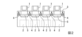
図2〜図5を参照して第2実施形態を説明する。なお、第1実施形態と共通の構成要素には同一の符号を付し、説明を簡略化する。
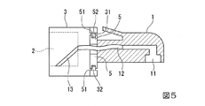
前記コネクタ1は、例えばRJ45(Registered Jack 45)タイプの規格に従った形状、寸法に構成されたLANコネクタ(実施形態の場合、RJ45タイプのプラグ側)であって、その内部には、LANケーブル等の導体線に接続される金属ピン11と、この金属ピン11にLANケーブル12を介して接続されてコネクタ2(実施形態の場合、RJ45タイプのジャック側)に接続される金属ピン13とが設けられている。
A second embodiment will be described with reference to FIGS. In addition, the same code | symbol is attached | subjected to the same component as 1st Embodiment, and description is simplified.
The connector 1 is, for example, a LAN connector (in the case of the embodiment, an RJ45 type plug side) configured in a shape and dimensions in accordance with an RJ45 (Registered Jack 45) type standard, and a LAN cable is included in the LAN connector. A
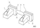
ゴム等の弾性体により形成された連結部材4は、それぞれコネクタ1が挿入される複数のグロメット本体5のうち、隣り合うグロメット本体5を互いに連結する。実施形態の場合、コネクタ1はグロメット本体5を貫通している。グロメット本体5は、ゴム等の弾性変形可能な材料により形成されていて、前記コネクタ1の挿入に伴い、わずかに弾性変形している。
The connecting
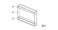
前記グロメット本体5は、例えばローゼット等の筐体である収容部3の開口部31に取り付けられている。前記開口部31は、図4に示すように、筐体3の一の面に、窓状に形成されており、前記開口部31の内周の上下には、図4および図5に示すように、上部から下方、下部から上方へ、それぞれ内側へ突出する凸部32が形成されている。この凸部32は、開口部31の幅方向に延びていて、前記グロメット本体5の上部、下部にそれぞれ形成された溝状の凹部51に挿入されている。前記グロメット本体51は、前述のように弾性変形可能な材料により形成されているため、容易に凹部51を変形させて凸部32に嵌め込むことができるようになっている。
The grommet
すなわち前記グロメット本体5は、凹部51が凸部32に対してスライドすることにより、図2の矢印A方向に互いに離間し、あるいは矢印Aと反対方向に互いに接近することができる。また図示の場合、前記グロメット本体5のスライド方向と前記弾性部材4の伸縮方向とが一致しているため、グロメット5の相互間隔を容易に調整することができる。
さらに、互いに連結されたグロメット本体5のうち、筐体3の内面に最も近い位置に配置されたもの(図2に示された4つのグロメット本体5の内、両端に位置するもの)は、前記連結部材4によって筐体3に連結されていて、連結部材4によって連結されたグロメット本体5全体を筐体3に対して移動可能に固定している。
That is, the
Furthermore, among the
上記構成の接続補助部材にあっては、凹部51に凸部32を嵌め込みながら、グロメット5とともにコネクタ1を筐体3に取り付けることができる。この際、弾性部材4を伸縮させることによって、コネクタ1をグロメット5と一体に図2の矢印A方向、もしくは反対方向へ移動させながら、各コネクタ1を筐体3内のコネクタ2に対して相対的に位置決めすることができる。
またコネクタ1が一列に並べられているので、例えば、コネクタ1の配列方向(図5の紙面と直交する方向)に所定の長さを持ったレバーを用いて操作することにより、複数のコネクタ1のロック解除等の操作を一括して行うことができる。
In the connection auxiliary member having the above configuration, the connector 1 can be attached to the
Further, since the connectors 1 are arranged in a line, for example, by operating using a lever having a predetermined length in the arrangement direction of the connectors 1 (direction orthogonal to the paper surface of FIG. 5), a plurality of connectors 1 It is possible to perform operations such as unlocking all at once.
また、複数のグロメット5にそれぞれ挿入されたコネクタ1は、グロメット本体5が連結部材4によって互いに連結されていることから、グロメット本体5から分離させない限り、所定の配列が維持される。すなわち、多数のコネクタ1を対応するコネクタ2から抜いた後にも、グロメット本体5が連結部材4によって一体に連結されているから、その配列が抜く前と同じに維持され、再接続に際して誤接続されるおそれが少ない。
Further, the connectors 1 inserted into the plurality of
なお一般に、コネクタ1は5の断面において上下非対称の形状であるから、挿入に際して、一連のコネクタの向き(図5において金属ピン11が正しく下向きとされるか誤って上向きとされるか)を誤るおそれは少ないが、例えば、グロメット本体5に上下の向きを示す文字、図形、色分け、外形状の相違等の目印となる表示を付しておくことにより、コネクタ1が対称形状で表裏の区別ができない場合にも、逆の配列で挿入してしまう誤りを防止することができる。
In general, since the connector 1 has an asymmetrical shape in the cross section of 5, a series of connector orientations (whether the metal pins 11 are correctly oriented downward or incorrectly oriented in FIG. 5) are erroneously inserted. Although there is little fear, for example, the
上記実施形態においてグロメット本体5が取り付けられる開口部31の形状は、グロメット本体5のはめ込みを考慮して、グロメット本体5の輪郭よりわずかに小さい程度にしても、あるいは、グロメット本体の配列方向(図4の紙面と直交する方向)へグロメット本体5の長さより十分に長い範囲にわたって開口させて、グロメット本体5の移動可能範囲を広げるようにしても良い。さらに、グロメット本体5の配列方向(連結部材4の弾性変形方向)へ連続する開口を設けて、さらにグロメット本体5の配列の自由度を高めるようにしても良い。
In the above embodiment, the shape of the
前記コネクタ1とグロメット本体5とは、ゴム等の弾性変形可能な材料により一体成形した構成であっても、グロメット本体5に形成した貫通孔にコネクタ1を嵌め込んで一体化した構成であっても良い。またグロメット本体5と連結部材4とについても、一体成形した構成であっても、着脱可能に連結した構成であっても良い。
またコネクタ1とグロメット本体5とを一体成形し、複数のグロメット本体5と連結部材4とを一体成形した場合には、LANケーブルの順序が変わらないため、再接続の際の誤りをより確実に防止することができる。また、これらを分離可能に連結した場合には、コネクタ、筐体の開口部の形状等に応じて、様々な形状のグロメット本体を適用することができ、接続補助具の」汎用性を高めることができる。
Even if the connector 1 and the
Further, when the connector 1 and the
グロメット本体5を互いに連結する連結部材4は、ゴム等の弾性変形可能でかつグロメット本体5との一体成形、あるいは接着等による固着に適した材料が用いられるが、例えば、グロメット本体5を引っ張りコイルばね、圧縮コイルばねによって連結する構造であっても良い。
The connecting
また、連結部材4とグロメット本体5との間は、一体成形や接着等の手段を用いる方が製造工程の簡略化の面で好ましいが、連結部材4を交換可能な構造とすることにより、例えば、筐体側のコネクタの相互間隔が一定でなく、弾性部材4の変形可能な限界を超えた配置等、多様な配置とされた場合に備えて、全部の連結部材4を同一長さとしたり、一部の連結部材4の長さを長くしてもよい。
Further, between the connecting
前記筐体3に設けられる凸部32は、筐体3に別部材を設けるのではなく、その開口部31の縁を利用して、この縁をグロメット本体5の凹部51に挿入して案内させるようにしても良い。また筐体3の凸部32とグロメット本体5の凹部51との凹凸を逆にしても良い。
The
なお、前記一方のコネクタ1は、互いの間隔を変更可能に連結されているので、このコネクタ1の相手となるコネクタ2が、例えば図示しないサーバ等に所定の間隔で設けられている場合に、このサーバ側のコネクタ2の相互の間隔に合わせて、コネクタ1の相互の間隔を調整することができる。また、この接続に際しても、コネクタ1が互いに連結されているので、その順序が代わって誤接続する可能性が小さい。
In addition, since the one connector 1 is connected so that the interval between the connectors 1 can be changed, when the
前記筐体3は、LANケーブルが接続されるローゼットとして使用されるが、ローゼット以外の電子機器、例えばパーソナルコンピュータやサーバ等、およそLANケーブル等の多くのケーブルが接続される、各種の電子機器の筐体に適用されて、ケーブル接続作業の労力の低減および誤接続の防止を図ることができる。
The
以上、本発明の実施形態について図面を参照して詳述したが、本発明は上記実施形態に限定されることなく、特許請求の範囲に記載した発明の範囲内で、種々の変形が可能であり、それらも本発明の範囲内に含まれるものであることはいうまでもない。 As mentioned above, although embodiment of this invention was explained in full detail with reference to drawings, this invention is not limited to the said embodiment, A various deformation | transformation is possible within the range of the invention described in the claim. Needless to say, they are also included in the scope of the present invention.
本発明は、LANケーブル等のコネクタを筐体に接続する際に利用される、接続補助部材、LANケーブル、筐体、及びグロメットに関する。 The present invention relates to a connection auxiliary member, a LAN cable, a casing, and a grommet that are used when a connector such as a LAN cable is connected to the casing.
1 コネクタ
2 コネクタ
3 収容部(筐体)
4 連結部材
5 グロメット本体
11 金属ピン
12 LANケーブル
13 金属ピン
31 開口部
32 凸部
51 溝部(凹部)
1
4 Connecting
Claims (6)
該一方のコネクタに対応する複数の雌雄何れか他方のコネクタと、
これら雌雄のコネクタの少なくとも一方を収容する収容部と、
を備え、
前記雌雄いずれか一方のコネクタは、互いの間隔を変更可能に連結され、
前記収容部を構成する筐体内に前記他方のコネクタを所定の配置で設け、
前記一方のコネクタがそれぞれ挿入される複数のグロメット本体と、
該グロメット本体の間に設けられて隣り合うグロメット本体を相対移動可能に連結する連結部材と、
を有する接続補助部材。 One of a plurality of male and female connectors,
A plurality of male or female connectors corresponding to the one connector, and the other connector;
An accommodating portion for accommodating at least one of the male and female connectors;
With
The male or female connector is connected so that the distance between each other can be changed ,
Provide the other connector in a predetermined arrangement in the housing constituting the housing portion,
A plurality of grommet bodies into which the one connector is inserted;
A connecting member that is provided between the grommet bodies and connects adjacent grommet bodies so as to be relatively movable;
A connection assisting member.
該複数のグロメット本体の相互間隔を変更可能に連結する連結部材と、
を有するグロメット。 A plurality of grommet bodies into which either one of the male and female connectors connected to each other is inserted;
A coupling member that couples the plurality of grommets to each other so as to be able to change the mutual spacing;
Grommet with.
Priority Applications (1)
| Application Number | Priority Date | Filing Date | Title |
|---|---|---|---|
| JP2017063676A JP6607222B2 (en) | 2017-03-28 | 2017-03-28 | Connection auxiliary member and grommet |
Applications Claiming Priority (1)
| Application Number | Priority Date | Filing Date | Title |
|---|---|---|---|
| JP2017063676A JP6607222B2 (en) | 2017-03-28 | 2017-03-28 | Connection auxiliary member and grommet |
Publications (2)
| Publication Number | Publication Date |
|---|---|
| JP2018166087A JP2018166087A (en) | 2018-10-25 |
| JP6607222B2 true JP6607222B2 (en) | 2019-11-20 |
Family
ID=63922165
Family Applications (1)
| Application Number | Title | Priority Date | Filing Date |
|---|---|---|---|
| JP2017063676A Active JP6607222B2 (en) | 2017-03-28 | 2017-03-28 | Connection auxiliary member and grommet |
Country Status (1)
| Country | Link |
|---|---|
| JP (1) | JP6607222B2 (en) |
Families Citing this family (1)
| Publication number | Priority date | Publication date | Assignee | Title |
|---|---|---|---|---|
| KR102499801B1 (en) * | 2021-03-29 | 2023-02-13 | 주식회사 현대케피코 | Variable connector and electronic control device including the same |
Family Cites Families (3)
| Publication number | Priority date | Publication date | Assignee | Title |
|---|---|---|---|---|
| JP2003133004A (en) * | 2001-10-24 | 2003-05-09 | Fujitsu I-Network Systems Ltd | Insertion error preventing structure for modular jack |
| US8545247B2 (en) * | 2011-06-30 | 2013-10-01 | Blackberry Limited | Dock for a portable electronic device |
| US9570849B2 (en) * | 2013-11-05 | 2017-02-14 | Commscope Technologies Llc | Float plate for blind matable electrical cable connectors |
-
2017
- 2017-03-28 JP JP2017063676A patent/JP6607222B2/en active Active
Also Published As
| Publication number | Publication date |
|---|---|
| JP2018166087A (en) | 2018-10-25 |
Similar Documents
| Publication | Publication Date | Title |
|---|---|---|
| CN103457072B (en) | electrical connector | |
| CN101032058B (en) | Locking structure for locking a cover onto a contact carrier module | |
| EP3179570A1 (en) | Connector apparatus | |
| EP1587178A1 (en) | A connector | |
| EP1962390B1 (en) | A connector and a connector assembly | |
| EP2835873A1 (en) | Connector and terminal | |
| JP2002203641A (en) | Electric connector | |
| JP6084136B2 (en) | USB receptacle | |
| JPH0619276U (en) | Female electrical terminal | |
| EP1689040A1 (en) | A connector and a method of assembling it | |
| KR20210000672U (en) | Connector | |
| CN107910680B (en) | An electromagnetic shielding connector module with multi-pin structure | |
| EP3213375B1 (en) | Hermaphroditic electrical connector and method of manufacturing it | |
| JP6607222B2 (en) | Connection auxiliary member and grommet | |
| KR20140135517A (en) | Universal usb socket | |
| CN116491028A (en) | Plugs, Connectors and Sockets | |
| US20180301841A1 (en) | Reversible connector interface | |
| EP2705580B1 (en) | Electrical connector plug with key to avoid contact damage | |
| EP2854227A1 (en) | Terminal and connector using the same | |
| CN111628316B (en) | A board-to-board connector | |
| CN113555745B (en) | mating connector | |
| EP2317609B1 (en) | Connector, series of connectors and method of assembling it | |
| US11283209B2 (en) | Connector housing for an electrical connector | |
| CN212085268U (en) | Board-to-board connector | |
| TWI922493B (en) | Plug, connector and receptacle |
Legal Events
| Date | Code | Title | Description |
|---|---|---|---|
| A621 | Written request for application examination |
Free format text: JAPANESE INTERMEDIATE CODE: A621 Effective date: 20180709 |
|
| A977 | Report on retrieval |
Free format text: JAPANESE INTERMEDIATE CODE: A971007 Effective date: 20190408 |
|
| A131 | Notification of reasons for refusal |
Free format text: JAPANESE INTERMEDIATE CODE: A131 Effective date: 20190416 |
|
| A521 | Written amendment |
Free format text: JAPANESE INTERMEDIATE CODE: A523 Effective date: 20190610 |
|
| TRDD | Decision of grant or rejection written | ||
| A01 | Written decision to grant a patent or to grant a registration (utility model) |
Free format text: JAPANESE INTERMEDIATE CODE: A01 Effective date: 20190924 |
|
| A61 | First payment of annual fees (during grant procedure) |
Free format text: JAPANESE INTERMEDIATE CODE: A61 Effective date: 20191007 |
|
| R150 | Certificate of patent or registration of utility model |
Ref document number: 6607222 Country of ref document: JP Free format text: JAPANESE INTERMEDIATE CODE: R150 |