JP6084136B2 - USB receptacle - Google Patents
USB receptacle Download PDFInfo
- Publication number
- JP6084136B2 JP6084136B2 JP2013175352A JP2013175352A JP6084136B2 JP 6084136 B2 JP6084136 B2 JP 6084136B2 JP 2013175352 A JP2013175352 A JP 2013175352A JP 2013175352 A JP2013175352 A JP 2013175352A JP 6084136 B2 JP6084136 B2 JP 6084136B2
- Authority
- JP
- Japan
- Prior art keywords
- usb
- shell
- special
- usb receptacle
- detection pin
- Prior art date
- Legal status (The legal status is an assumption and is not a legal conclusion. Google has not performed a legal analysis and makes no representation as to the accuracy of the status listed.)
- Expired - Fee Related
Links
Images


Classifications
-
- H—ELECTRICITY
- H01—ELECTRIC ELEMENTS
- H01R—ELECTRICALLY-CONDUCTIVE CONNECTIONS; STRUCTURAL ASSOCIATIONS OF A PLURALITY OF MUTUALLY-INSULATED ELECTRICAL CONNECTING ELEMENTS; COUPLING DEVICES; CURRENT COLLECTORS
- H01R13/00—Details of coupling devices of the kinds covered by groups H01R12/70 or H01R24/00 - H01R33/00
- H01R13/66—Structural association with built-in electrical component
- H01R13/70—Structural association with built-in electrical component with built-in switch
- H01R13/703—Structural association with built-in electrical component with built-in switch operated by engagement or disengagement of coupling parts, e.g. dual-continuity coupling part
-
- H—ELECTRICITY
- H01—ELECTRIC ELEMENTS
- H01R—ELECTRICALLY-CONDUCTIVE CONNECTIONS; STRUCTURAL ASSOCIATIONS OF A PLURALITY OF MUTUALLY-INSULATED ELECTRICAL CONNECTING ELEMENTS; COUPLING DEVICES; CURRENT COLLECTORS
- H01R13/00—Details of coupling devices of the kinds covered by groups H01R12/70 or H01R24/00 - H01R33/00
- H01R13/648—Protective earth or shield arrangements on coupling devices, e.g. anti-static shielding
- H01R13/6485—Electrostatic discharge protection
-
- H—ELECTRICITY
- H01—ELECTRIC ELEMENTS
- H01R—ELECTRICALLY-CONDUCTIVE CONNECTIONS; STRUCTURAL ASSOCIATIONS OF A PLURALITY OF MUTUALLY-INSULATED ELECTRICAL CONNECTING ELEMENTS; COUPLING DEVICES; CURRENT COLLECTORS
- H01R12/00—Structural associations of a plurality of mutually-insulated electrical connecting elements, specially adapted for printed circuits, e.g. printed circuit boards [PCB], flat or ribbon cables, or like generally planar structures, e.g. terminal strips, terminal blocks; Coupling devices specially adapted for printed circuits, flat or ribbon cables, or like generally planar structures; Terminals specially adapted for contact with, or insertion into, printed circuits, flat or ribbon cables, or like generally planar structures
- H01R12/70—Coupling devices
- H01R12/71—Coupling devices for rigid printing circuits or like structures
-
- H—ELECTRICITY
- H01—ELECTRIC ELEMENTS
- H01R—ELECTRICALLY-CONDUCTIVE CONNECTIONS; STRUCTURAL ASSOCIATIONS OF A PLURALITY OF MUTUALLY-INSULATED ELECTRICAL CONNECTING ELEMENTS; COUPLING DEVICES; CURRENT COLLECTORS
- H01R13/00—Details of coupling devices of the kinds covered by groups H01R12/70 or H01R24/00 - H01R33/00
- H01R13/66—Structural association with built-in electrical component
- H01R13/665—Structural association with built-in electrical component with built-in electronic circuit
- H01R13/6683—Structural association with built-in electrical component with built-in electronic circuit with built-in sensor
-
- H—ELECTRICITY
- H01—ELECTRIC ELEMENTS
- H01R—ELECTRICALLY-CONDUCTIVE CONNECTIONS; STRUCTURAL ASSOCIATIONS OF A PLURALITY OF MUTUALLY-INSULATED ELECTRICAL CONNECTING ELEMENTS; COUPLING DEVICES; CURRENT COLLECTORS
- H01R29/00—Coupling parts for selective co-operation with a counterpart in different ways to establish different circuits, e.g. for voltage selection, for series-parallel selection, programmable connectors
Description
本発明は、少なくとも2種類の相手側コネクタと嵌合可能なコネクタであって、嵌合された相手側コネクタのタイプを識別するための検知機構を備えるコネクタに関する。 The present invention relates to a connector that can be fitted to at least two types of mating connectors and includes a detection mechanism for identifying the type of mating mating connector.
このタイプのコネクタは、例えば、特許文献1に開示されている。
This type of connector is disclosed in
図27及び図28に示されるように、特許文献1に開示されたコネクタは、USB(Universal Serial Bus)規格に準拠したUSBレセプタクルである。USBレセプタクルは、USB規格に準拠した標準USBプラグ(図示せず)及び特殊USBプラグと、嵌合方向に沿って選択的に嵌合可能である。特殊USBプラグは、金属等の導電体からなる特殊シェルを備えている。特殊シェルは、標準USBプラグに含まれていない識別部を有している。USBレセプタクルは、導電体からなるシェルと、樹脂等の絶縁体からなる保持部材と、導電体からなる検知ピンとを備えている。保持部材は、シェルに覆われており、検知ピンを保持している。
As shown in FIGS. 27 and 28, the connector disclosed in
USBレセプタクルと特殊USBプラグとを嵌合方向に沿って互いに嵌合させると、特殊シェルの識別部が検知ピンと接触して電気的に接続され、これにより、USBレセプタクルは、特殊USBプラグと嵌合したことを検知することができる。このため、特殊USBプラグと嵌合したUSBレセプタクルは、標準USBプラグと嵌合したUSBレセプタクルと異なるように動作できる。 When the USB receptacle and the special USB plug are fitted to each other along the fitting direction, the identification part of the special shell comes into contact with the detection pin and is electrically connected, so that the USB receptacle is fitted with the special USB plug. Can be detected. For this reason, the USB receptacle fitted with the special USB plug can operate differently from the USB receptacle fitted with the standard USB plug.
特許文献1の特殊USBプラグがUSBレセプタクルと嵌合する際、特殊シェルの識別部は、保持部材の側面に沿って移動する。このとき、識別部の先端部が保持部材の側面に当たって側面を削り、削りカスが識別部によって検知ピンまで運ばれて検知ピンに付着するおそれがある。削りカスが検知ピンに付着すると、検知ピンと識別部とが電気的に良好に接続されないおそれがある。
When the special USB plug of
そこで、本発明は、USBプラグの識別部と接触する検知ピンを備えたUSBレセプタクルであって、検知ピンと識別部との良好な電気的接続を保つことが可能なUSBレセプタクルを提供することを目的とする。 Accordingly, an object of the present invention is to provide a USB receptacle having a detection pin that comes into contact with an identification portion of a USB plug, and capable of maintaining a good electrical connection between the detection pin and the identification portion. And
本発明は、第1のUSBレセプタクルとして、
USB規格に準拠した標準USBプラグと前記標準USBプラグとは異なる構造を有する少なくとも一種の特殊USBプラグとを所定方向に沿って選択的に嵌合抜去可能なUSBレセプタクルであって、
前記標準USBプラグは導電体からなる標準シェルを備えており、
前記特殊USBプラグは導電体からなる特殊シェルを備えており、
前記特殊シェルは前記所定方向において前記標準シェルよりも突出した識別部を有しており、
前記USBレセプタクルは、複数のコンタクトと、前記所定方向と直交するピッチ方向に前記コンタクトを列設保持する絶縁体からなる保持部材と、前記所定方向と直交する面内において前記保持部材を囲う導電体からなるシェルと、前記シェルとは別体の導電体からなる検知ピンとを備えており、
前記コンタクトは、接点部を有しており、
前記保持部材は、前記所定方向及び前記ピッチ方向の双方と直交する垂直方向において厚みを有し且つ前記所定方向に延びる板状の主部を有しており、
前記コンタクトの前記接点部は、前記主部の上面上に配置されており、
前記シェルは、前記USBレセプタクルを前記標準USBプラグと嵌合した際には前記標準シェルと接続可能な形状で且つ前記USBレセプタクルを前記特殊USBプラグと嵌合した際には前記特殊シェルと接続可能な形状を有しており、
前記検知ピンは、接触部を有しており、
前記検知ピンは、前記USBレセプタクルを前記標準USBプラグと嵌合した際には前記標準シェルが前記接触部まで到達しない位置であって前記USBレセプタクルを前記特殊USBプラグと嵌合した際には前記特殊シェルの前記識別部が前記接触部に接続される位置において、前記シェルに対して直接接続しないように前記保持部材の側部に保持されており、
前記接触部は、前記垂直方向と直交する水平面内において移動可能であり、
前記接触部は、前記垂直方向において前記保持部材の前記主部とまったく重なっておらず、
前記USBレセプタクルを前記特殊USBプラグと嵌合した際、前記接触部は、前記特殊シェルの前記識別部の前記ピッチ方向における内側に接続される
USBレセプタクルを提供する。
The present invention provides the first USB receptacle as
A USB receptacle capable of selectively fitting and removing a standard USB plug conforming to the USB standard and at least one special USB plug having a structure different from the standard USB plug along a predetermined direction,
The standard USB plug has a standard shell made of a conductor,
The special USB plug has a special shell made of a conductor,
The special shell has an identification portion protruding from the standard shell in the predetermined direction,
The USB receptacle includes a plurality of contacts, a holding member made of an insulator that holds the contacts in a pitch direction orthogonal to the predetermined direction, and a conductor that surrounds the holding member in a plane orthogonal to the predetermined direction. And a detection pin made of a conductor separate from the shell,
The contact has a contact portion,
The holding member has a plate-like main portion having a thickness in a vertical direction perpendicular to both the predetermined direction and the pitch direction and extending in the predetermined direction;
The contact portion of the contact is disposed on an upper surface of the main portion;
The shell can be connected to the standard shell when the USB receptacle is fitted to the standard USB plug, and can be connected to the special shell when the USB receptacle is fitted to the special USB plug. Have a shape,
The detection pin has a contact portion,
The detection pin is a position where the standard shell does not reach the contact portion when the USB receptacle is fitted with the standard USB plug, and when the USB receptacle is fitted with the special USB plug, At the position where the identification part of the special shell is connected to the contact part, it is held on the side of the holding member so as not to be directly connected to the shell,
The contact portion is movable in a horizontal plane perpendicular to the vertical direction;
The contact portion does not overlap the main portion of the holding member in the vertical direction at all,
When the USB receptacle is fitted to the special USB plug, the contact portion provides a USB receptacle connected to the inside of the identification portion of the special shell in the pitch direction.
また、本発明は、第2のUSBレセプタクルとして、第1のUSBレセプタクルであって、
前記検知ピンは、被規制部を有しており、
前記保持部材の前記主部には前記ピッチ方向の外側へ向かう前記被規制部の移動を規制する規制部が形成されている
USBレセプタクルを提供する。
The present invention also provides a first USB receptacle as the second USB receptacle,
The detection pin has a regulated portion,
Provided is a USB receptacle in which a restricting portion for restricting movement of the restricted portion toward the outside in the pitch direction is formed in the main portion of the holding member.
また、本発明は、第3のUSBレセプタクルとして、第2のUSBレセプタクルであって、
前記保持部材の前記主部は、前記被規制部の前記水平面内における移動を許容する移動許容部を有している
USBレセプタクルを提供する。
Further, the present invention is a second USB receptacle as the third USB receptacle,
The main portion of the holding member provides a USB receptacle having a movement allowing portion that allows movement of the restricted portion in the horizontal plane.
また、本発明は、第4のUSBレセプタクルとして、第1乃至第3のUSBレセプタクルのいずれかであって、
前記検知ピンは、被保持部と、前記被保持部から延びる弾性変形可能なバネ部とを有しており、
前記接触部は、前記バネ部に設けられており、
前記保持部材は、前記被保持部を保持するピン保持部を有している
USBレセプタクルを提供する。
Further, the present invention is any one of the first to third USB receptacles as the fourth USB receptacle,
The detection pin has a held portion and an elastically deformable spring portion extending from the held portion,
The contact portion is provided on the spring portion,
The holding member provides a USB receptacle having a pin holding portion for holding the held portion.
また、本発明は、第5のUSBレセプタクルとして、第4のUSBレセプタクルであって、
前記保持部材は、前記バネ部の弾性変形を許容する変形許容部を有しており、
前記変形許容部は、前記所定方向において前記検知ピンの前記被保持部から前記接触部に近づくに連れて前記ピッチ方向のサイズが大きくなるように形成されている
USBレセプタクルを提供する。
The present invention also provides a fourth USB receptacle as the fifth USB receptacle,
The holding member has a deformation allowing portion that allows elastic deformation of the spring portion,
The deformation allowing portion provides a USB receptacle formed so that the size in the pitch direction increases as the contact portion approaches the contact portion from the held portion of the detection pin in the predetermined direction.
また、本発明は、第6のUSBレセプタクルとして、第4又は第5のUSBレセプタクルであって、
前記ピン保持部は、前記ピッチ方向と直交する垂直面内に延びる溝であり、
前記被保持部と前記バネ部とは、前記垂直面内に延びており、且つ、前記ピッチ方向において前記ピン保持部よりもサイズの小さいものであり、
前記検知ピンには、前記被保持部を前記ピン保持部の内壁に押し付けるダボが形成されている
USBレセプタクルを提供する。
The present invention also provides a fourth or fifth USB receptacle as the sixth USB receptacle,
The pin holding portion is a groove extending in a vertical plane orthogonal to the pitch direction,
The held portion and the spring portion extend in the vertical plane, and are smaller in size than the pin holding portion in the pitch direction,
The detection pin is provided with a USB receptacle in which a dowel for pressing the held portion against the inner wall of the pin holding portion is formed.
また、本発明は、第7のUSBレセプタクルとして、第6のUSBレセプタクルであって、
前記検知ピンには、前記保持部材に圧入される圧入ポストが形成されており、
前記ダボは前記圧入ポストの近傍に形成されている
USBレセプタクルを提供する。
The present invention also provides a sixth USB receptacle as the seventh USB receptacle,
The detection pin is formed with a press-fit post that is press-fitted into the holding member,
The dowel provides a USB receptacle formed in the vicinity of the press-fit post.
また、本発明は、第8のUSBレセプタクルとして、第4乃至第7のUSBレセプタクルのいずれかであって、
前記バネ部は、前記垂直方向及び前記所定方向の双方と斜交する方向に延びている
USBレセプタクルを提供する。
Further, the present invention is any of the fourth to seventh USB receptacles as the eighth USB receptacle,
The spring portion provides a USB receptacle extending in a direction oblique to both the vertical direction and the predetermined direction.
また、本発明は、第9のUSBレセプタクルとして、第1乃至第8のUSBレセプタクルのいずれかであって、
前記識別部には、第1識別部と第2識別部の二種類あり、
前記検知ピンには、前記第1識別部と接続可能な第1検知ピンと、前記第2識別部と接続可能な第2検知ピンとの二種類あり、
前記第1検知ピン及び前記第2検知ピンは、前記保持部材の前記ピッチ方向の側部に夫々保持されている
USBレセプタクルを提供する。
Further, the present invention is any one of the first to eighth USB receptacles as the ninth USB receptacle,
The identification unit has two types, a first identification unit and a second identification unit,
There are two types of detection pins: a first detection pin that can be connected to the first identification unit, and a second detection pin that can be connected to the second identification unit.
The first detection pin and the second detection pin provide USB receptacles that are respectively held on the sides of the holding member in the pitch direction.
本発明によれば、検知ピンの接触部は、垂直方向において保持部材の主部とまったく重なっていない。このため、主部の側面が特殊USBプラグの識別部によって削られたとしても、削りカスは検知ピンの接触部まで到達しない。従って、検知ピンと識別部との良好な電気的接続を保つことができる。 According to the present invention, the contact portion of the detection pin does not overlap the main portion of the holding member in the vertical direction. For this reason, even if the side surface of the main part is scraped by the identification part of the special USB plug, the scraped scrap does not reach the contact part of the detection pin. Therefore, a good electrical connection between the detection pin and the identification unit can be maintained.
図1に示されるように、本発明の実施の形態によるUSBレセプタクル100は、回路基板800の切欠き810に取り付けられる所謂落とし込みタイプのコネクタである。但し、本発明は、落とし込みタイプのコネクタ以外にも適用可能である。例えば、本発明は、所謂オンボードタイプのコネクタにも適用可能である。
As shown in FIG. 1, a
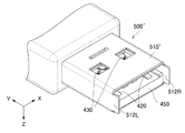
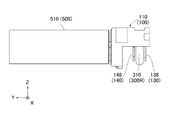
図19及び図20に示されるように、USBレセプタクル100は、特殊USBプラグ500と所定方向(Y方向)に沿って嵌合可能である。更に、USBレセプタクル100は、標準USBプラグ400(図6参照)及び特殊USBプラグ500′(図8参照)の夫々とY方向に沿って嵌合可能である。即ち、USBレセプタクル100は、標準USBプラグ400と少なくとも一種の特殊USBプラグ(特殊USBプラグ500及び特殊USBプラグ500′)とがY方向に沿って選択的に嵌合抜去可能となるように構成されている。
As shown in FIGS. 19 and 20, the
後述するように、本実施の形態によるUSBレセプタクル100は、嵌合されたUSBプラグ(即ち、相手側プラグ)が特殊USBプラグであるか標準USBプラグ400(図6参照)であるかを検知可能である。換言すれば、USBレセプタクル100には、相手側プラグを検知可能な検知機構が設けられている。以下においては、まずUSBレセプタクル100と嵌合可能な標準USBプラグ400、特殊USBプラグ500(図7参照)及び特殊USBプラグ500′(図8参照)の夫々の構造について説明する。その後、USBレセプタクル100の構造について説明する。
As will be described later, the
図6に示されるように、標準USBプラグ400は、USB規格のうちの1つであるUSB3.0規格に準拠したUSBプラグである。標準USBプラグ400は、金属等の導電体からなる標準シェル410(相手側シェル)と、導電体からなる複数の標準コンタクト420と、導電体からなる複数の標準コンタクト430と、絶縁体からなる標準保持部材450とを備えている。標準シェル410及び標準保持部材450の夫々は、USB3.0規格に準拠した形状及びサイズを有している。標準コンタクト420はUSB2.0接続用のコンタクトであり、標準コンタクト430はUSB3.0接続用のコンタクトである。標準保持部材450は、標準コンタクト420及び標準コンタクト430を保持している。標準シェル410は、標準保持部材450を覆っている。
As shown in FIG. 6, the
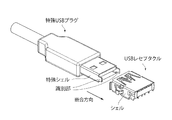
図6及び図7を参照すると、本実施の形態による特殊USBプラグ500は、標準USBプラグ400と同様であるが少し異なる構造を有している。特殊USBプラグ500は、金属等の導電体からなる特殊シェル510(相手側シェル)と、複数の標準コンタクト420(図6参照)と、複数の標準コンタクト430と、標準保持部材450とを備えている。特殊シェル510は、標準保持部材450を覆っている。
Referring to FIGS. 6 and 7, the
特殊シェル510は、Y方向において標準シェル410と異なるサイズを有している。詳しくは、特殊シェル510は、標準シェル410に含まれていない識別部512を有している。本実施の形態による特殊シェル510は、識別部512を除くと、標準シェル410と同じ形状及びサイズを有している。換言すれば、特殊シェル510は、標準シェル410と同じ形状及びサイズを有する主部を有している。識別部512は、−Y方向において特殊シェル510の主部(即ち、標準シェル410)よりも突出している。このため、特殊シェル510全体のY方向におけるサイズは、識別部512のサイズだけ標準シェル410よりも大きい。
The
図7に示されるように、本実施の形態による識別部512は、四角環形状を有している。詳しくは、識別部512は、第1識別部(識別部)512Rと第2識別部(識別部)512Lの二種類の識別部を含んでいる。第1識別部512R及び第2識別部512Lは、X方向(ピッチ方向)における識別部512の両側部に夫々位置している。第1識別部512Rと第2識別部512Lとは、Y方向と直交する面内において互いに連結されている。
As shown in FIG. 7, the
図7及び図8を参照すると、特殊USBプラグ500′(図8参照)は、特殊USBプラグ500(図7参照)の特殊シェル510の識別部512のみを変形することによって形成されている。詳しくは、特殊USBプラグ500′は、特殊シェル510′(相手側シェル)を有している。特殊シェル510′は、特殊シェル510と同様に、第1識別部512R及び第2識別部512Lを有している。但し、特殊シェル510′は、Y方向と直交する面内において第1識別部512Rと第2識別部512Lとを連結する部位を有していない。特殊USBプラグ500′は、USBレセプタクル100(図2参照)の検知機構に関して、特殊USBプラグ500と同じ種類の特殊USBプラグである。即ち、本実施の形態によるUSBレセプタクル100は、2種類のUSBプラグ(標準USBプラグ400及び1種類の特殊USBプラグ)を識別可能である。
7 and 8, the
特殊USBプラグ500′の特殊シェル510′は、更に変形可能である。例えば、特殊シェル510′の第1識別部512Rのみを有する第2の特殊USBプラグ(図示せず)や第2識別部512Lのみを有する第3の特殊USBプラグ(図示せず)を形成することができる。
The
上述したように、特殊USBプラグ500及び特殊USBプラグ500′は、USBレセプタクル100(図2参照)の検知機構に関して同じ構造を備えている。特殊USBプラグ500についての以降の説明は、特殊USBプラグ500′についても該当する。このため、以降は、特殊USBプラグ500′については説明しない。
As described above, the
図1乃至図4に示されるように、本実施の形態によるUSBレセプタクル100は、コネクタ本体110と、導電体からなるシェル120とを備えている。シェル120は、Y方向と直交する面(XZ平面)内においてコネクタ本体110を囲んでいる。
As shown in FIGS. 1 to 4, the
本実施の形態によるシェル120は、概略、角筒状の形状を有している。即ち、シェル120は、Y方向と直交する面内において概ね矩形の断面を有している。シェル120の矩形の断面は、X方向(ピッチ方向)において長く、Z方向(垂直方向)において短い。
The
図2、図4及び図5に示されるように、シェル120のX方向における両側面には、シェル接続部122が夫々形成されている。シェル接続部122は、USBレセプタクル100が特殊USBプラグ500と嵌合した際に、特殊シェル510と接続される(図20参照)。また、シェル接続部122は、USBレセプタクル100が標準USBプラグ400(図6参照)と嵌合した際に、標準シェル410と接続される。即ち、USBレセプタクル100が標準USBプラグ400又は特殊USBプラグ500と嵌合すると、シェル120は、標準シェル410又は特殊シェル510と電気的に接続される。
As shown in FIGS. 2, 4, and 5,
図1及び図2から理解されるように、シェル120のX方向における両側部には、2つの被固定部126が夫々形成されている。USBレセプタクル100が回路基板800に取り付けられるとき、被固定部126は、回路基板800に形成された孔に夫々挿入されて導体パターン(図示せず)に夫々接続される。
As understood from FIGS. 1 and 2, two fixed
図2及び図5から理解されるように、シェル120には、2つの取付部128が設けられている。取付部128は、シェル120のX方向における両側面の後端(−Y側の端)に夫々形成されている。取付部128は、前方に向かって(+Y方向に沿って)切欠かれた切欠きである。即ち、取付部128は、前方に向かって凹んでいる。
As understood from FIGS. 2 and 5, the
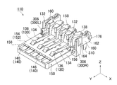
図9乃至図11に示されるように、コネクタ本体110(即ち、USBレセプタクル100)は、導電体からなる複数のコンタクト130と、導電体からなる複数のコンタクト140と、樹脂等の絶縁体からなる保持部材150と、導電体からなる第1検知ピン(検知ピン)300Rと、導電体からなる第2検知ピン(検知ピン)300Lとを備えている。保持部材150は、コンタクト130をX方向に列設保持しており、且つ、コンタクト140をX方向に列設保持している。第1検知ピン300R及び第2検知ピン300Lの夫々は、シェル120(図4参照)と別体に形成されている。換言すれば、第1検知ピン300R及び第2検知ピン300Lの夫々は、シェル120と別体である。
As shown in FIGS. 9 to 11, the connector main body 110 (that is, the USB receptacle 100) is made of a plurality of
コンタクト130は、USB2.0接続用のコンタクトであり、コンタクト140は、USB3.0接続用のコンタクトである。本実施の形態によれば、コンタクト130の本数は4本であり、コンタクト140の本数は5本である。コンタクト130の夫々は、被保持部132と、バネ部134と、接点部136と、被固定部138とを有している。被保持部132は、保持部材150に保持されている。バネ部134は、被保持部132から上方(+Z方向)に傾斜しつつ前方に延びている。接点部136は、バネ部134の先端に設けられている。コンタクト140の夫々は、接点部146と、被固定部148(図15参照)とを有している。被固定部138及び被固定部148は、USBレセプタクル100が回路基板800(図1参照)に取り付けられたとき、回路基板800の導体パターン(図示せず)に夫々接続される。
The
保持部材150は、主部152と、コンタクト保持部158とを有している。主部152は、Z方向において厚みを有し且つY方向に延びる板形状を有している。主部152は、上面154と2つの側面156とを有している。側面156は、主部152のX方向における両側部に夫々位置している。コンタクト保持部158は、主部152の後側(−Y側)に位置している。コンタクト保持部158は、2つの側部160を有している。側部160は、コンタクト保持部158のX方向における両側部に夫々位置している。
The holding
コンタクト130の被保持部132は、保持部材150のコンタクト保持部158に圧入されており、下方に向かって(−Z方向に沿って)延びている。接点部136は、主部152の上面154上に、部分的に突出するようにして配置されている。コンタクト130のバネ部134は、弾性変形可能であり、これにより接点部136は、主としてZ方向に移動可能である。
The held
図9乃至図11を参照すると、コンタクト140は、保持部材150の成型時に、保持部材150にインサート成型されている。即ち、コンタクト140は、保持部材150に部分的に埋め込まれている。コンタクト140の接点部146は、主部152の上面154上に配置されている。コンタクト140の接点部146は、コンタクト130の接点部136と比べて、主部152の前端(+Y側の端)に近い位置に位置している。換言すれば、コンタクト140の接点部146は、Y方向において、コンタクト130の接点部136と主部152の前端との間に位置している。
9 to 11, the
図11及び図12に示されるように、コンタクト保持部158の側部160の夫々には、ピン保持部162と、変形許容部164と、移動許容部166と、規制部168と、取付部176とが形成されている。
As shown in FIGS. 11 and 12, each of the
ピン保持部162は、X方向と直交する方向に延びる溝である。詳しくは、ピン保持部162は、X方向と直交する垂直面(YZ平面)内を延びつつ、Z方向において側部160を部分的に貫通している。即ち、ピン保持部162の一部は、保持部材150の底面まで延びている。
The
変形許容部164及び移動許容部166は、下方に(−Z方向に)凹んだ凹みである。変形許容部164は、ピン保持部162から+Y方向に延びている。即ち、変形許容部164は、ピン保持部162の前方に位置している。移動許容部166は、変形許容部164の前方に位置している。換言すれば、変形許容部164は、Y方向においてピン保持部162と移動許容部166との間に位置している。規制部168は、Y方向に僅かに延びる壁である。規制部168は、移動許容部166のX方向外側に位置している。
The
変形許容部164のX方向におけるサイズは、ピン保持部162から移動許容部166に近づくに連れて大きくなるように構成されている。詳しくは、本実施の形態による変形許容部164は、2つの壁によって規定されている。2つの壁は、X方向において互いから離れつつ、+Y方向に延びている。このように構成された変形許容部164は、保持部材150の強度(特に、側部160の強度)を殆ど低下させない。
The size of the
図12に示されるように、移動許容部166は、X方向において規制部168と主部152との間に位置している。移動許容部166のX方向内側の端は、変形許容部164よりもX方向において内側に位置している。
As shown in FIG. 12, the
図9に示されるように、取付部176は、側部160の後端に位置している。取付部176は、前方に向かって延びる板状の形状を有している。また、取付部176は、側部160からX方向外側に突出している。シェル120の取付部128(図2参照)は、後方に向かって(−Y方向に沿って)取付部176に嵌合されており、これによりシェル120が保持部材150に取り付けられている。
As shown in FIG. 9, the
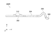
図10に示されるように、第1検知ピン300Rと第2検知ピン300Lとは、X方向と直交する面に関して互いに鏡像である形状を有している。即ち、第2検知ピン300Lは、以下に説明する第1検知ピン300Rの構造と同様な構造を有している。
As shown in FIG. 10, the
図16乃至図18に示されるように、第1検知ピン300Rは、被保持部302と、バネ部304と、接触部306と、被規制部308と、圧入ポスト310とを有している。被保持部302は、平板形状を有している。被保持部302には、2つのダボ312が設けられている。ダボ312は、被保持部302のX方向外側の面に形成されている。バネ部304は、被保持部302から全体として下方に傾斜しつつ前方に延びている。接触部306は、バネ部304の先端に設けられている。バネ部304は、X方向において弾性変形可能である。接触部306は、バネ部304の弾性変形により、主としてX方向に移動可能である。被規制部308は、接触部306の下方に位置している。被規制部308と接触部306とは、Z方向に延びる部位によって互いに連結されている。圧入ポスト310は、被保持部302から下方に延びている。ダボ312のうちの1つは、被保持部302と圧入ポスト310との間の境界部分に位置している。圧入ポスト310は、USBレセプタクル100が回路基板800(図1参照)に取り付けられたとき、回路基板800の導体パターン(図示せず)に接続される。
As shown in FIGS. 16 to 18, the first detection pin 300 </ b> R includes a held
図16乃至図18から理解されるように、被保持部302、バネ部304及び圧入ポスト310は、同一の垂直面(YZ平面)内を延びている。換言すれば、被保持部302、バネ部304及び圧入ポスト310は、同一平面を構成している。一方、接触部306及び被規制部308のみは、バネ部304を含む平面上に位置していない。即ち、第1検知ピン300Rは、最低限の曲げを有するように形成されている。本実施の形態による被保持部302、バネ部304及び圧入ポスト310の夫々の厚み(即ち、X方向におけるサイズ)は、ピン保持部162のX方向におけるサイズよりも小さい(図12参照)。本実施の形態による接触部306は、バネ部304を含む平面から張り出した曲面を有している。接触部306の曲面は、ピッチ方向(X方向)及び所定方向(Y方向)によって規定される面内(XY平面内)においてX方向の外側に張り出している。
As can be understood from FIGS. 16 to 18, the held
図9乃至図12に示されるように、第1検知ピン300R及び第2検知ピン300Lは、+X側の側部160及び−X側の側部160に夫々保持されている。詳しくは、第1検知ピン300R及び第2検知ピン300Lの圧入ポスト310は、上方から−Z方向に沿ってピン保持部162に夫々挿入(圧入)され、これにより被保持部302は、ピン保持部162内に夫々保持されている。
As shown in FIGS. 9 to 12, the
図10乃至図12から理解されるように、圧入ポスト310がピン保持部162に圧入される際、被保持部302のダボ312は、ピン保持部162の内壁に押し付けられる。即ち、ダボ312は、ピン保持部162の内壁に被保持部302を押し付ける。本実施の形態によれば、第1検知ピン300R及び第2検知ピン300Lの夫々のバネ部304の固定端が明確であるため、設計通りのバネ力を得ることができる。特に、本実施の形態によるダボ312は、圧入ポスト310の近傍に設けられている。このため、第1検知ピン300R及び第2検知ピン300Lがピン保持部162に夫々圧入されるのとほぼ同時に、第1検知ピン300R及び第2検知ピン300Lがダボ312によってX方向において夫々位置決めされる。従って、被保持部302をピン保持部162の内壁に確実に固定することができる。
As can be understood from FIGS. 10 to 12, when the press-
図4から理解されるように、側部160に保持された第1検知ピン300R及び第2検知ピン300Lは、シェル120と接触していない。換言すれば、第1検知ピン300R及び第2検知ピン300Lは、シェル120と直接的に接続しないように、保持部材150に保持されている。
As understood from FIG. 4, the first detection pin 300 </ b> R and the second detection pin 300 </ b> L held on the
図12に示されるように、第1検知ピン300R及び第2検知ピン300Lが側部160に夫々保持されたとき、バネ部304は変形許容部164内に位置している。このため、バネ部304は、変形許容部164内において弾性変形可能である。換言すれば、変形許容部164は、バネ部304の弾性変形を許容するように構成されている。
As shown in FIG. 12, when the first detection pin 300 </ b> R and the second detection pin 300 </ b> L are held on the
図9及び図10から理解されるように、第1検知ピン300R及び第2検知ピン300Lが側部160に夫々保持されたとき、バネ部304は、被保持部302から、+Y方向及び−Z方向によって規定される方向に延びている。換言すれば、バネ部304は、Z方向及びY方向の双方と斜交する方向に延びている。このため、バネ部304の長さを大きくすることができる。更に、変形許容部164は、Y方向において被保持部302から接触部306に近づくに連れてX方向におけるサイズが大きくなるように形成されている。このように構成された変形許容部164に配置されたバネ部304は、X方向において十分に弾性変形できる。
As can be understood from FIGS. 9 and 10, when the first detection pin 300 </ b> R and the second detection pin 300 </ b> L are held on the
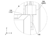
図11及び図12に示されるように、第1検知ピン300R及び第2検知ピン300Lが側部160に夫々保持されたとき、接触部306は、Z方向と直交する水平面(XY平面)内において移動可能である。また、接触部306は、主部152の側面156からX方向の外側に夫々突出している。図4に示されるように、USBレセプタクル100を嵌合端側から(前側から)見たとき、接触部306を視認することができる。
As shown in FIGS. 11 and 12, when the
図13乃至図15に示されるように、接触部306は、Z方向において主部152とまったく重なっていない。特に、本実施の形態による接触部306は、Z方向において主部152の側面156とまったく重なっていない。即ち、接触部306と主部152とをZ方向と直交する任意の方向に沿ってZ方向と平行な平面に投影した場合、接触部306の投影像は、主部152の投影像と重ならない。本実施の形態による接触部306の下端(−Z側の端)は、Z方向において主部152の上面154よりも僅かに上方に位置している。換言すれば、接触部306は、主部152の僅かに上方に位置している。但し、接触部306は、Z方向において主部152の上面154から大きく離れていてもよい。
As shown in FIGS. 13 to 15, the
図11及び図12に示されるように、第1検知ピン300R及び第2検知ピン300Lが側部160に夫々保持されたとき、被規制部308は、移動許容部166内に位置している。被規制部308は、バネ部304が弾性変形した際に、移動許容部166内において移動可能である。換言すれば、移動許容部166は、被規制部308の水平面内における移動を許容するように構成されている。
As shown in FIGS. 11 and 12, when the first detection pin 300 </ b> R and the second detection pin 300 </ b> L are held on the
規制部168は、X方向において被規制部308の外側へ向かう移動を規制するように構成されている。詳しくは、規制部168は、X方向において被規制部308と接触部306との間に位置している。即ち、規制部168は、X方向において被規制部308の外側に位置している。このため、X方向外側に向かう力が接触部306に加わったとしても、被規制部308が規制部168に突き当たり、これによって接触部306の過度な移動を防止する。規制部168は、X方向において外側面を有している。本実施の形態によれば、規制部168の外側面と主部152の側面156とは、面一に形成されている。但し、規制部168の外側面は、X方向において、主部152の側面156よりも内側に位置していてもよい。
The restricting
図4及び図12を参照すると、被規制部308は、主部152の上面154から下方に凹んだ規制部168内に位置している。このため、USBレセプタクル100を嵌合端側から見たとき、被規制部308を視認することはできない。本実施の形態によれば、何らかの部材や部位が−Y方向に沿って被規制部308に接触することを防ぐことができる。
Referring to FIGS. 4 and 12, the
図19乃至図26に示されるように、特殊USBプラグ500が−Y方向に沿ってUSBレセプタクル100と嵌合すると、特殊シェル510の第1識別部512R及び第2識別部512Lは、第1検知ピン300R及び第2検知ピン300Lの接触部306と夫々接触する。即ち、本実施の形態によるUSBレセプタクル100は、第1識別部512R及び第2識別部512Lと夫々接続可能な2種類の第1検知ピン300R及び第2検知ピン300Lを備えている。
As shown in FIGS. 19 to 26, when the
図23、図25及び図26から理解されるように、USBレセプタクル100と特殊USBプラグ500とが嵌合した嵌合状態において、規制部168は、特殊シェル510のX方向における内側に位置する。また、嵌合状態において、接触部306は、特殊シェル510の識別部512の内側に接続される。接触部306をこのように構成することで、USBレセプタクル100のX方向におけるサイズを比較的小さくすることができる。また、本実施の形態によれば、接触部306の曲面の一部が、第1識別部512R及び第2識別部512LのX方向における内側と夫々接触する。このため、接触部306の接点は明瞭である。
As understood from FIGS. 23, 25, and 26, in the fitting state in which the
図25から理解されるように、特殊USBプラグ500がUSBレセプタクル100と嵌合する際、識別部512を除いて、特殊シェル510のどの部位も、Y方向において第1検知ピン300R及び第2検知ピン300Lに到達できない。即ち、標準USBプラグ400(図6参照)がUSBレセプタクル100と嵌合する際、標準シェル410は、第1検知ピン300R及び第2検知ピン300Lと接触しない。換言すれば、接触部306は、USBレセプタクル100を標準USBプラグ400と嵌合した際に、標準シェル410が到達しない位置に配置されている。即ち、第1検知ピン300R及び第2検知ピン300Lは、USBレセプタクル100を標準USBプラグ400と嵌合した際には標準シェル410が接触部306まで到達しない位置に保持されている。一方、第1検知ピン300R及び第2検知ピン300Lは、USBレセプタクル100を特殊USBプラグ500と嵌合した際には特殊シェル510の識別部512が接触部306に接続される位置に保持されている。
As can be understood from FIG. 25, when the
図19及び図20から理解されるように、シェル120は、USBレセプタクル100が標準USBプラグ400(図6参照)及び特殊USBプラグ500の夫々と嵌合した際に、シェル接続部122を介して標準シェル410又は特殊シェル510と接続する。即ち、シェル120は、USBレセプタクル100を標準USBプラグ400と嵌合した際には標準シェル410と接続可能な形状で、且つ、USBレセプタクル100を特殊USBプラグ500と嵌合した際には特殊シェル510と接続可能な形状を有している。第1検知ピン300R及び第2検知ピン300Lは、USBレセプタクル100と標準USBプラグ400との嵌合の際にはシェル120と電気的に接続されない一方、USBレセプタクル100と特殊USBプラグ500との嵌合の際には特殊シェル510を介してシェル120と電気的に接続される。
As understood from FIGS. 19 and 20, the
図14及び図26から理解されるように、接触部306がZ方向において主部152の上方に位置しているため、識別部512のうち接触部306に接続される部位は、主部152の側面156の上方に位置している。このため、USBレセプタクル100と特殊USBプラグ500とが嵌合する際(図22参照)、識別部512が主部152の側面156を削ったとしても、削りカスは接触部306に付着し難い。従って、第1検知ピン300R及び第2検知ピン300Lと特殊シェル510の第1識別部512R及び第2識別部512Lとの良好な電気的接続を保つことができる。
As understood from FIGS. 14 and 26, since the
図20及び図25から理解されるように、本実施の形態によれば、第1検知ピン300R及び第2検知ピン300Lとシェル120とが電気的に接続されたか否かを検知することで、USBレセプタクル100が標準USBプラグ400(図6参照)と嵌合したのか特殊USBプラグ500と嵌合したのかを検知することができる。即ち、USBレセプタクル100の相手側プラグの種類を識別することができる。より具体的には、例えば、電流を検知することにより相手側プラグの種類を識別することができる。この場合、シェル120と第1検知ピン300R及び第2検知ピン300Lの夫々との間に電流が流れているか否かを検知すればよい。また、電位を検知することによっても相手側プラグの種類を識別することができる。この場合、第1検知ピン300R及び第2検知ピン300Lの電位をプルアップする一方、シェル120をグランドに接続しておけばよい。その上で、第1検知ピン300R及び第2検知ピン300Lの夫々の電位に変動があるか(即ち、グランド電位まで低下したか)否かを検知すればよい。
As understood from FIGS. 20 and 25, according to the present embodiment, by detecting whether the
上述のように電流又は電圧を検知する場合、第1検知ピン300Rに関する第1検知と第2検知ピン300Lに関する第2検知とを互いに独立に行うことができる。第1検知と第2検知とを独立に行う場合、特殊USBプラグ500だけでなく、第1識別部512Rのみを有する第2の特殊USBプラグ(図示せず)や第2識別部512Lのみを有する第3の特殊USBプラグ(図示せず)を識別することが可能である。詳しくは、第1検知ピン300R及び第2検知ピン300Lの双方がシェル120と電気的に接続されていることを検知した場合には、USBレセプタクル100に対して特殊USBプラグ500が接続されていることが分かる。また、第2検知ピン300Lのみがシェル120と電気的に接続されていることを検知した場合には、USBレセプタクル100に対して第3の特殊USBプラグが接続されていることが分かる。また、第1検知ピン300Rのみがシェル120と電気的に接続されていることを検知した場合には、USBレセプタクル100に対して第2の特殊USBプラグが接続されていることが分かる。また、第1検知ピン300R及び第2検知ピン300Lの双方がシェル120と電気的に接続されていないことを検知した場合には、USBレセプタクル100に対して標準USBプラグ400が接続されていることが分かる。
When the current or voltage is detected as described above, the first detection related to the
100 USBレセプタクル
110 コネクタ本体
120 シェル
122 シェル接続部
126 被固定部
128 取付部
130 コンタクト
132 被保持部
134 バネ部
136 接点部
138 被固定部
140 コンタクト
146 接点部
148 被固定部
150 保持部材
152 主部
154 上面
156 側面
158 コンタクト保持部
160 側部
162 ピン保持部
164 変形許容部
166 移動許容部
168 規制部
176 取付部
300R 第1検知ピン(検知ピン)
300L 第2検知ピン(検知ピン)
302 被保持部
304 バネ部
306 接触部
308 被規制部
310 圧入ポスト
312 ダボ
400 標準USBプラグ
410 標準シェル
420 標準コンタクト
430 標準コンタクト
450 標準保持部材
500,500′ 特殊USBプラグ
510,510′ 特殊シェル
512 識別部
512R 第1識別部(識別部)
512L 第2識別部(識別部)
800 回路基板
810 切欠き
DESCRIPTION OF
300L second detection pin (detection pin)
302
512L second identification unit (identification unit)
800
Claims (9)
前記標準USBプラグは導電体からなる標準シェルを備えており、
前記特殊USBプラグは導電体からなる特殊シェルを備えており、
前記特殊シェルは前記所定方向において前記標準シェルよりも突出した識別部を有しており、
前記USBレセプタクルは、複数のコンタクトと、前記所定方向と直交するピッチ方向に前記コンタクトを列設保持する絶縁体からなる保持部材と、前記所定方向と直交する面内において前記保持部材を囲う導電体からなるシェルと、前記シェルとは別体の導電体からなる検知ピンとを備えており、
前記コンタクトは、接点部を有しており、
前記保持部材は、前記所定方向及び前記ピッチ方向の双方と直交する垂直方向において厚みを有し且つ前記所定方向に延びる板状の主部を有しており、
前記コンタクトの前記接点部は、前記主部の上面上に配置されており、
前記シェルは、前記USBレセプタクルを前記標準USBプラグと嵌合した際には前記標準シェルと接続可能な形状で且つ前記USBレセプタクルを前記特殊USBプラグと嵌合した際には前記特殊シェルと接続可能な形状を有しており、
前記検知ピンは、接触部を有しており、
前記検知ピンは、前記USBレセプタクルを前記標準USBプラグと嵌合した際には前記標準シェルが前記接触部まで到達しない位置であって前記USBレセプタクルを前記特殊USBプラグと嵌合した際には前記特殊シェルの前記識別部が前記接触部に接続される位置において、前記シェルに対して直接接続しないように前記保持部材の側部に保持されており、
前記接触部は、前記垂直方向と直交する水平面内において移動可能であり、
前記接触部は、前記垂直方向において前記保持部材の前記主部とまったく重なっておらず、
前記USBレセプタクルを前記特殊USBプラグと嵌合した際、前記接触部は、前記特殊シェルの前記識別部の前記ピッチ方向における内側に接続される
USBレセプタクル。 A USB receptacle capable of selectively fitting and removing a standard USB plug conforming to the USB standard and at least one special USB plug having a structure different from the standard USB plug along a predetermined direction,
The standard USB plug has a standard shell made of a conductor,
The special USB plug has a special shell made of a conductor,
The special shell has an identification portion protruding from the standard shell in the predetermined direction,
The USB receptacle includes a plurality of contacts, a holding member made of an insulator that holds the contacts in a pitch direction orthogonal to the predetermined direction, and a conductor that surrounds the holding member in a plane orthogonal to the predetermined direction. And a detection pin made of a conductor separate from the shell,
The contact has a contact portion,
The holding member has a plate-like main portion having a thickness in a vertical direction perpendicular to both the predetermined direction and the pitch direction and extending in the predetermined direction;
The contact portion of the contact is disposed on an upper surface of the main portion;
The shell can be connected to the standard shell when the USB receptacle is fitted to the standard USB plug, and can be connected to the special shell when the USB receptacle is fitted to the special USB plug. Have a shape,
The detection pin has a contact portion,
The detection pin is a position where the standard shell does not reach the contact portion when the USB receptacle is fitted with the standard USB plug, and when the USB receptacle is fitted with the special USB plug, At the position where the identification part of the special shell is connected to the contact part, it is held on the side of the holding member so as not to be directly connected to the shell,
The contact portion is movable in a horizontal plane perpendicular to the vertical direction;
The contact portion does not overlap the main portion of the holding member in the vertical direction at all,
When the USB receptacle is fitted with the special USB plug, the contact portion is connected to the inside of the identification portion of the special shell in the pitch direction.
前記検知ピンは、被規制部を有しており、
前記保持部材の前記主部には前記ピッチ方向の外側へ向かう前記被規制部の移動を規制する規制部が形成されている
USBレセプタクル。 The USB receptacle according to claim 1,
The detection pin has a regulated portion,
A USB receptacle in which a restricting portion for restricting movement of the restricted portion toward the outside in the pitch direction is formed in the main portion of the holding member.
前記保持部材の前記主部は、前記被規制部の前記水平面内における移動を許容する移動許容部を有している
USBレセプタクル。 The USB receptacle according to claim 2,
The USB receptacle in which the main portion of the holding member has a movement allowing portion that allows movement of the restricted portion in the horizontal plane.
前記検知ピンは、被保持部と、前記被保持部から延びる弾性変形可能なバネ部とを有しており、
前記接触部は、前記バネ部に設けられており、
前記保持部材は、前記被保持部を保持するピン保持部を有している
USBレセプタクル。 A USB receptacle according to any one of claims 1 to 3,
The detection pin has a held portion and an elastically deformable spring portion extending from the held portion,
The contact portion is provided on the spring portion,
The holding member is a USB receptacle having a pin holding portion for holding the held portion.
前記保持部材は、前記バネ部の弾性変形を許容する変形許容部を有しており、
前記変形許容部は、前記所定方向において前記検知ピンの前記被保持部から前記接触部に近づくに連れて前記ピッチ方向のサイズが大きくなるように形成されている
USBレセプタクル。 The USB receptacle according to claim 4,
The holding member has a deformation allowing portion that allows elastic deformation of the spring portion,
The deformation allowing portion is a USB receptacle formed so that the size in the pitch direction increases as the contact portion approaches the contact portion from the held portion of the detection pin in the predetermined direction.
前記ピン保持部は、前記ピッチ方向と直交する垂直面内に延びる溝であり、
前記被保持部と前記バネ部とは、前記垂直面内に延びており、且つ、前記ピッチ方向において前記ピン保持部よりもサイズの小さいものであり、
前記検知ピンには、前記被保持部を前記ピン保持部の内壁に押し付けるダボが形成されている
USBレセプタクル。 A USB receptacle according to claim 4 or claim 5, wherein
The pin holding portion is a groove extending in a vertical plane orthogonal to the pitch direction,
The held portion and the spring portion extend in the vertical plane, and are smaller in size than the pin holding portion in the pitch direction,
A USB receptacle in which the detection pin is formed with a dowel that presses the held portion against the inner wall of the pin holding portion.
前記検知ピンには、前記保持部材に圧入される圧入ポストが形成されており、
前記ダボは前記圧入ポストの近傍に形成されている
USBレセプタクル。 The USB receptacle according to claim 6,
The detection pin is formed with a press-fit post that is press-fitted into the holding member,
The dowel is a USB receptacle formed in the vicinity of the press-fitting post.
前記バネ部は、前記垂直方向及び前記所定方向の双方と斜交する方向に延びている
USBレセプタクル。 A USB receptacle according to any one of claims 4 to 7,
The USB portion is a USB receptacle that extends in a direction oblique to both the vertical direction and the predetermined direction.
前記識別部には、第1識別部と第2識別部の二種類あり、
前記検知ピンには、前記第1識別部と接続可能な第1検知ピンと、前記第2識別部と接続可能な第2検知ピンとの二種類あり、
前記第1検知ピン及び前記第2検知ピンは、前記保持部材の前記ピッチ方向の側部に夫々保持されている
USBレセプタクル。 A USB receptacle according to any one of claims 1 to 8,
The identification unit has two types, a first identification unit and a second identification unit,
There are two types of detection pins: a first detection pin that can be connected to the first identification unit, and a second detection pin that can be connected to the second identification unit.
The first detection pin and the second detection pin are USB receptacles that are respectively held on side portions of the holding member in the pitch direction.
Priority Applications (5)
| Application Number | Priority Date | Filing Date | Title |
|---|---|---|---|
| JP2013175352A JP6084136B2 (en) | 2013-08-27 | 2013-08-27 | USB receptacle |
| US14/444,227 US9281634B2 (en) | 2013-08-27 | 2014-07-28 | USB receptacle |
| TW103125792A TWI505585B (en) | 2013-08-27 | 2014-07-29 | Usb receptacle |
| KR1020140096145A KR101613167B1 (en) | 2013-08-27 | 2014-07-29 | Usb receptacle |
| CN201410392592.6A CN104426003B (en) | 2013-08-27 | 2014-08-11 | Usb receptacle |
Applications Claiming Priority (1)
| Application Number | Priority Date | Filing Date | Title |
|---|---|---|---|
| JP2013175352A JP6084136B2 (en) | 2013-08-27 | 2013-08-27 | USB receptacle |
Publications (3)
| Publication Number | Publication Date |
|---|---|
| JP2015046240A JP2015046240A (en) | 2015-03-12 |
| JP2015046240A5 JP2015046240A5 (en) | 2016-06-02 |
| JP6084136B2 true JP6084136B2 (en) | 2017-02-22 |
Family
ID=52583858
Family Applications (1)
| Application Number | Title | Priority Date | Filing Date |
|---|---|---|---|
| JP2013175352A Expired - Fee Related JP6084136B2 (en) | 2013-08-27 | 2013-08-27 | USB receptacle |
Country Status (5)
| Country | Link |
|---|---|
| US (1) | US9281634B2 (en) |
| JP (1) | JP6084136B2 (en) |
| KR (1) | KR101613167B1 (en) |
| CN (1) | CN104426003B (en) |
| TW (1) | TWI505585B (en) |
Families Citing this family (7)
| Publication number | Priority date | Publication date | Assignee | Title |
|---|---|---|---|---|
| JP6114675B2 (en) * | 2013-10-24 | 2017-04-12 | 日本航空電子工業株式会社 | Receptacle connector |
| CN203800219U (en) * | 2013-12-11 | 2014-08-27 | 富士康(昆山)电脑接插件有限公司 | Electric connector |
| US9915695B2 (en) * | 2014-12-01 | 2018-03-13 | Toshiba Global Commerce Solutions Holdings Corporation | Detecting a proper connection |
| EP3544126B1 (en) | 2016-12-08 | 2021-09-22 | Huawei Technologies Co., Ltd. | Device having usb port |
| DE102018000204A1 (en) * | 2018-01-12 | 2019-07-18 | Kostal Kontakt Systeme Gmbh | The connector assembly |
| DE102018000207A1 (en) * | 2018-01-12 | 2019-07-18 | Kostal Kontakt Systeme Gmbh | The connector assembly |
| KR102638653B1 (en) * | 2018-10-04 | 2024-02-21 | 삼성전자주식회사 | Receptacle and electronic device having the same |
Family Cites Families (11)
| Publication number | Priority date | Publication date | Assignee | Title |
|---|---|---|---|---|
| CN1601818A (en) * | 2003-09-25 | 2005-03-30 | 莫列斯公司 | Electronic card connector |
| CN201130767Y (en) * | 2007-10-12 | 2008-10-08 | 富士康(昆山)电脑接插件有限公司 | Electric Connector |
| CN102044800A (en) * | 2009-10-22 | 2011-05-04 | 惠州华阳通用电子有限公司 | Method and device for detecting access of USB equipment and USB socket thereof |
| CN202094354U (en) | 2011-06-03 | 2011-12-28 | 东莞宇球电子有限公司 | Electric connector with detecting function |
| JP5826638B2 (en) * | 2011-06-20 | 2015-12-02 | 日本航空電子工業株式会社 | USB connector |
| JP5826646B2 (en) | 2011-09-09 | 2015-12-02 | 日本航空電子工業株式会社 | Special receptacle and special plug |
| TWI497848B (en) * | 2011-06-20 | 2015-08-21 | Japan Aviation Electron | Special usb plug having different structure from standard usb plug and usb receptacle matable with the special usb plug |
| US8690608B2 (en) * | 2011-06-20 | 2014-04-08 | Japan Aviation Electronics Industry Limited | Special USB plug having different structure from standard USB plug and USB receptacle matable with the special USB plug |
| JP2012138383A (en) | 2012-04-23 | 2012-07-19 | Japan Aviation Electronics Industry Ltd | Connector device |
| CN103427236B (en) * | 2012-05-25 | 2016-03-23 | 富士康(昆山)电脑接插件有限公司 | Electric connector |
| CN202855957U (en) * | 2012-08-14 | 2013-04-03 | 富士康(昆山)电脑接插件有限公司 | Electric connector |
-
2013
- 2013-08-27 JP JP2013175352A patent/JP6084136B2/en not_active Expired - Fee Related
-
2014
- 2014-07-28 US US14/444,227 patent/US9281634B2/en not_active Expired - Fee Related
- 2014-07-29 TW TW103125792A patent/TWI505585B/en not_active IP Right Cessation
- 2014-07-29 KR KR1020140096145A patent/KR101613167B1/en active IP Right Grant
- 2014-08-11 CN CN201410392592.6A patent/CN104426003B/en not_active Expired - Fee Related
Also Published As
| Publication number | Publication date |
|---|---|
| KR20150024770A (en) | 2015-03-09 |
| JP2015046240A (en) | 2015-03-12 |
| KR101613167B1 (en) | 2016-04-18 |
| US20150064958A1 (en) | 2015-03-05 |
| TWI505585B (en) | 2015-10-21 |
| US9281634B2 (en) | 2016-03-08 |
| CN104426003B (en) | 2017-04-12 |
| CN104426003A (en) | 2015-03-18 |
| TW201530936A (en) | 2015-08-01 |
Similar Documents
| Publication | Publication Date | Title |
|---|---|---|
| JP6084136B2 (en) | USB receptacle | |
| JP5826673B2 (en) | USB connector | |
| JP6761736B2 (en) | connector | |
| CN103904489B (en) | Adapter | |
| JP7348090B2 (en) | connector assembly | |
| WO2008050665A1 (en) | Connector | |
| JP6084133B2 (en) | connector | |
| KR101526354B1 (en) | Connector and terminal | |
| WO2008044324A1 (en) | Connector | |
| JP2007324029A (en) | Terminal for electric connection, and connector using it | |
| US20120309240A1 (en) | Electrical receptacle terminal | |
| JP6265770B2 (en) | connector | |
| JP2014513391A (en) | Prior ground connection by spring member | |
| KR20140073417A (en) | Connector | |
| TWI399889B (en) | Connector | |
| JP5866129B2 (en) | Pair of mating electrical connectors | |
| TWI575821B (en) | Usb receptacle | |
| US20160099522A1 (en) | Connector | |
| WO2021112258A1 (en) | Connector | |
| TW201607156A (en) | Connector | |
| TWM517453U (en) | Power connector | |
| JP6049689B2 (en) | Electrical plug connector connection device with leading contact | |
| JP2019114500A (en) | connector |
Legal Events
| Date | Code | Title | Description |
|---|---|---|---|
| A521 | Written amendment |
Free format text: JAPANESE INTERMEDIATE CODE: A523 Effective date: 20160408 |
|
| A621 | Written request for application examination |
Free format text: JAPANESE INTERMEDIATE CODE: A621 Effective date: 20160408 |
|
| A977 | Report on retrieval |
Free format text: JAPANESE INTERMEDIATE CODE: A971007 Effective date: 20161227 |
|
| TRDD | Decision of grant or rejection written | ||
| A01 | Written decision to grant a patent or to grant a registration (utility model) |
Free format text: JAPANESE INTERMEDIATE CODE: A01 Effective date: 20170104 |
|
| A61 | First payment of annual fees (during grant procedure) |
Free format text: JAPANESE INTERMEDIATE CODE: A61 Effective date: 20170124 |
|
| R150 | Certificate of patent or registration of utility model |
Ref document number: 6084136 Country of ref document: JP Free format text: JAPANESE INTERMEDIATE CODE: R150 |
|
| LAPS | Cancellation because of no payment of annual fees |