JP6084133B2 - connector - Google Patents
connector Download PDFInfo
- Publication number
- JP6084133B2 JP6084133B2 JP2013164975A JP2013164975A JP6084133B2 JP 6084133 B2 JP6084133 B2 JP 6084133B2 JP 2013164975 A JP2013164975 A JP 2013164975A JP 2013164975 A JP2013164975 A JP 2013164975A JP 6084133 B2 JP6084133 B2 JP 6084133B2
- Authority
- JP
- Japan
- Prior art keywords
- contact
- connector
- mating
- state
- spring
- Prior art date
- Legal status (The legal status is an assumption and is not a legal conclusion. Google has not performed a legal analysis and makes no representation as to the accuracy of the status listed.)
- Active
Links
- 230000013011 mating Effects 0.000 claims description 140
- 230000005489 elastic deformation Effects 0.000 claims description 53
- 239000002184 metal Substances 0.000 claims description 8
- 238000004080 punching Methods 0.000 claims description 3
- 238000005452 bending Methods 0.000 description 7
- 238000005192 partition Methods 0.000 description 7
- 238000000926 separation method Methods 0.000 description 6
- 239000011810 insulating material Substances 0.000 description 5
- 239000004020 conductor Substances 0.000 description 4
- 230000004048 modification Effects 0.000 description 3
- 238000012986 modification Methods 0.000 description 3
- 230000000295 complement effect Effects 0.000 description 1
- 238000005476 soldering Methods 0.000 description 1
Images


Classifications
-
- H—ELECTRICITY
- H01—ELECTRIC ELEMENTS
- H01R—ELECTRICALLY-CONDUCTIVE CONNECTIONS; STRUCTURAL ASSOCIATIONS OF A PLURALITY OF MUTUALLY-INSULATED ELECTRICAL CONNECTING ELEMENTS; COUPLING DEVICES; CURRENT COLLECTORS
- H01R12/00—Structural associations of a plurality of mutually-insulated electrical connecting elements, specially adapted for printed circuits, e.g. printed circuit boards [PCB], flat or ribbon cables, or like generally planar structures, e.g. terminal strips, terminal blocks; Coupling devices specially adapted for printed circuits, flat or ribbon cables, or like generally planar structures; Terminals specially adapted for contact with, or insertion into, printed circuits, flat or ribbon cables, or like generally planar structures
- H01R12/70—Coupling devices
- H01R12/82—Coupling devices connected with low or zero insertion force
- H01R12/85—Coupling devices connected with low or zero insertion force contact pressure producing means, contacts activated after insertion of printed circuits or like structures
-
- H—ELECTRICITY
- H01—ELECTRIC ELEMENTS
- H01R—ELECTRICALLY-CONDUCTIVE CONNECTIONS; STRUCTURAL ASSOCIATIONS OF A PLURALITY OF MUTUALLY-INSULATED ELECTRICAL CONNECTING ELEMENTS; COUPLING DEVICES; CURRENT COLLECTORS
- H01R12/00—Structural associations of a plurality of mutually-insulated electrical connecting elements, specially adapted for printed circuits, e.g. printed circuit boards [PCB], flat or ribbon cables, or like generally planar structures, e.g. terminal strips, terminal blocks; Coupling devices specially adapted for printed circuits, flat or ribbon cables, or like generally planar structures; Terminals specially adapted for contact with, or insertion into, printed circuits, flat or ribbon cables, or like generally planar structures
- H01R12/70—Coupling devices
- H01R12/71—Coupling devices for rigid printing circuits or like structures
- H01R12/712—Coupling devices for rigid printing circuits or like structures co-operating with the surface of the printed circuit or with a coupling device exclusively provided on the surface of the printed circuit
- H01R12/716—Coupling device provided on the PCB
-
- H—ELECTRICITY
- H01—ELECTRIC ELEMENTS
- H01R—ELECTRICALLY-CONDUCTIVE CONNECTIONS; STRUCTURAL ASSOCIATIONS OF A PLURALITY OF MUTUALLY-INSULATED ELECTRICAL CONNECTING ELEMENTS; COUPLING DEVICES; CURRENT COLLECTORS
- H01R12/00—Structural associations of a plurality of mutually-insulated electrical connecting elements, specially adapted for printed circuits, e.g. printed circuit boards [PCB], flat or ribbon cables, or like generally planar structures, e.g. terminal strips, terminal blocks; Coupling devices specially adapted for printed circuits, flat or ribbon cables, or like generally planar structures; Terminals specially adapted for contact with, or insertion into, printed circuits, flat or ribbon cables, or like generally planar structures
- H01R12/70—Coupling devices
- H01R12/71—Coupling devices for rigid printing circuits or like structures
- H01R12/72—Coupling devices for rigid printing circuits or like structures coupling with the edge of the rigid printed circuits or like structures
- H01R12/73—Coupling devices for rigid printing circuits or like structures coupling with the edge of the rigid printed circuits or like structures connecting to other rigid printed circuits or like structures
-
- H—ELECTRICITY
- H01—ELECTRIC ELEMENTS
- H01R—ELECTRICALLY-CONDUCTIVE CONNECTIONS; STRUCTURAL ASSOCIATIONS OF A PLURALITY OF MUTUALLY-INSULATED ELECTRICAL CONNECTING ELEMENTS; COUPLING DEVICES; CURRENT COLLECTORS
- H01R13/00—Details of coupling devices of the kinds covered by groups H01R12/70 or H01R24/00 - H01R33/00
- H01R13/02—Contact members
- H01R13/22—Contacts for co-operating by abutting
- H01R13/24—Contacts for co-operating by abutting resilient; resiliently-mounted
- H01R13/2464—Contacts for co-operating by abutting resilient; resiliently-mounted characterized by the contact point
- H01R13/2492—Contacts for co-operating by abutting resilient; resiliently-mounted characterized by the contact point multiple contact points
Description
本発明は、相手側コンタクトを備えた相手側コネクタと嵌合可能なコネクタであって、相手側コンタクトと2点で接触するコンタクトを備えたコネクタに関する。 The present invention relates to a connector that can be mated with a mating connector provided with a mating contact, and includes a contact that contacts the mating contact at two points.
このタイプのコネクタは、例えば特許文献1及び特許文献2に開示されている。
This type of connector is disclosed in
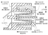
図24に示されるように、特許文献1の第1コネクタ(コネクタ)は、コンタクト(相手側コンタクト)を備えた第2コネクタ(相手側コネクタ)と嵌合方向に沿って嵌合可能である。相手側コンタクトは、2つの接触部(相手側第1接点部及び相手側第2接点部)を有している。第1コネクタは、コンタクトを備えている。第1コネクタのコンタクトは、2つの接触部(第1接点部及び第2接点部)を有している。第1コネクタと第2コネクタとが互いに嵌合した嵌合状態において、第1接点部は相手側第2接点部と接触し、第2接点部は相手側第1接点部と接触する。
As shown in FIG. 24, the first connector (connector) of
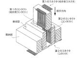
図25に示されるように、特許文献2の第2のコネクタ(コネクタ)は、第1のコンタクト(相手側コンタクト)を備えた第1のコネクタ(相手側コネクタ)と嵌合方向に沿って嵌合可能である。第2のコネクタは、フローティングコネクタである。詳しくは、第2のコネクタは、筒状部と、嵌合部と、第1のコンタクトと2点で接触する第2のコンタクト(コンタクト)とを備えている。嵌合部は嵌合方向と直交する面内において移動可能となるように筒状部に支持されている。第2のコンタクトは、嵌合部に保持されている。 As FIG. 25 shows, the 2nd connector (connector) of patent document 2 is fitted along the fitting direction with the 1st connector (mating side connector) provided with the 1st contact (mating side contact). Is possible. The second connector is a floating connector. Specifically, the second connector includes a cylindrical portion, a fitting portion, and a second contact (contact) that contacts the first contact at two points. The fitting portion is supported by the cylindrical portion so as to be movable in a plane orthogonal to the fitting direction. The second contact is held by the fitting portion.
特許文献1の第1コネクタの第1接点部は、実質的に移動しないように支持されている一方、第2コネクタの相手側第2接点部は、嵌合方向と直交する上下方向に移動可能となるように弾性支持されている。第1コネクタが、第2コネクタに対して相対的に上方に移動した場合、第1接点部と相手側第2接点部との間の接触力が弱まるおそれがある。同様に、第1コネクタが、第2コネクタに対して相対的に下方に移動した場合、第2接点部と相手側第1接点部との間の接触力が弱まるおそれがある。即ち、特許文献1の構造によれば、コンタクト間の接触信頼性が低下するおそれがある。
The first contact portion of the first connector of
特許文献2のコンタクトは、嵌合部の筒状部に対する相対的な移動によって移動する。このとき、コンタクトと相手側コンタクトとの間の接触信頼性が低下するおそれがある。 The contact of patent document 2 moves by relative movement with respect to the cylindrical part of a fitting part. At this time, the contact reliability between the contact and the counterpart contact may be reduced.
そこで、本発明は、相手側コンタクトと2点で接触するコンタクトであって、相手側コンタクトとの接触信頼性を高めるための新たな構造を有するコンタクトを備えたコネクタを提供することを目的とする。 SUMMARY OF THE INVENTION Accordingly, an object of the present invention is to provide a connector provided with a contact that contacts a counterpart contact at two points and has a new structure for improving contact reliability with the counterpart contact. .
本発明は、第1のコネクタとして、
相手側コンタクトを備えた相手側コネクタと嵌合方向に沿って嵌合可能なコネクタであって、前記相手側コネクタと嵌合した嵌合状態において前記相手側コンタクトと2点で接触するコンタクトを備えており、
前記コンタクトは、突出部と、第1バネ部と、スライド部と、第2バネ部とを有しており、
前記突出部は、前記第1バネ部から突出しており、且つ、第1接点部を有しており、
前記第1接点部は、前記第1バネ部の弾性変形によって、前記嵌合方向と直交する所定方向において移動量を有するように移動可能であり、前記嵌合状態において前記相手側コンタクトと接触し、
前記スライド部は、平坦に延びており、且つ、第2接点部を有しており、
前記第2接点部は、前記第2バネ部の弾性変形によって、前記所定方向において移動量を有するように移動可能であり、
前記コネクタが前記相手側コネクタと嵌合し始めた嵌合開始状態から前記嵌合状態に移動するまでの間、前記相手側コンタクトの一部である相手側接点部が前記スライド部上を移動し、前記嵌合状態においては、前記相手側接点部が前記第2接点部に到達し、
前記コネクタが前記嵌合開始状態から前記嵌合状態に移動するとき、前記第1接点部及び前記第2接点部のうちの一方は、前記第1バネ部の弾性変形によって前記所定方向において移動しつつ、前記第2バネ部の弾性変形によって前記所定方向において移動する
コネクタを提供する。
The present invention provides the first connector as
A connector that can be mated with a mating connector provided with a mating contact along a mating direction, and includes a contact that contacts the mating contact at two points in a mated state mated with the mating connector. And
The contact has a protruding portion, a first spring portion, a slide portion, and a second spring portion,
The protruding portion protrudes from the first spring portion and has a first contact portion,
The first contact portion is movable by an elastic deformation of the first spring portion so as to have a movement amount in a predetermined direction orthogonal to the fitting direction, and contacts the counterpart contact in the fitted state. ,
The slide portion extends flat and has a second contact portion,
The second contact portion is movable so as to have a moving amount in the predetermined direction by elastic deformation of the second spring portion,
The mating contact portion, which is a part of the mating contact, moves on the slide portion until the connector moves from the mating start state where the connector starts mating with the mating connector to the mating state. In the fitted state, the counterpart contact portion reaches the second contact portion,
When the connector moves from the fitting start state to the fitting state, one of the first contact portion and the second contact portion moves in the predetermined direction by elastic deformation of the first spring portion. Meanwhile, a connector is provided that moves in the predetermined direction by elastic deformation of the second spring portion.
また、本発明は、第2のコネクタとして、第1のコネクタであって、
前記コネクタが前記嵌合開始状態から前記嵌合状態に移動するとき、前記第1接点部は、前記第1バネ部の前記弾性変形によって前記所定方向において第1の距離だけ移動し、前記第2接点部は、前記第2バネ部の前記弾性変形によって前記所定方向において第2の距離だけ移動し、
前記第2の距離は前記第1の距離よりも大きい
コネクタを提供する。
Moreover, this invention is a 1st connector as a 2nd connector,
When the connector moves from the fitting start state to the fitting state, the first contact portion moves by a first distance in the predetermined direction by the elastic deformation of the first spring portion, and the second The contact portion moves by a second distance in the predetermined direction by the elastic deformation of the second spring portion,
The second distance provides a connector that is greater than the first distance.
また、本発明は、第3のコネクタとして、第1のコネクタであって、
前記コネクタが前記嵌合開始状態から前記嵌合状態に移動するとき、前記第1接点部は、前記第1バネ部の前記弾性変形によって前記所定方向において第1の距離だけ移動し、前記第2接点部は、前記第2バネ部の前記弾性変形によって前記所定方向において第2の距離だけ移動し、
前記第1の距離は前記第2の距離よりも大きい
コネクタを提供する。
Moreover, this invention is a 1st connector as a 3rd connector,
When the connector moves from the fitting start state to the fitting state, the first contact portion moves by a first distance in the predetermined direction by the elastic deformation of the first spring portion, and the second The contact portion moves by a second distance in the predetermined direction by the elastic deformation of the second spring portion,
The first distance provides a connector that is greater than the second distance.
また、本発明は、第4のコネクタとして、第1乃至第3のコネクタのいずれかであって、
前記第1接点部は、前記所定方向において前記第2接点部と異なる位置にあり、
前記コネクタを前記嵌合方向に沿って見たとき、前記第1接点部及び前記第2接点部を視認可能である
コネクタを提供する。
Moreover, this invention is either the 1st thru | or 3rd connector as a 4th connector,
The first contact portion is at a position different from the second contact portion in the predetermined direction,
Provided is a connector in which the first contact portion and the second contact portion are visible when the connector is viewed along the fitting direction.
また、本発明は、第5のコネクタとして、第1乃至第4のコネクタのいずれかであって、
前記コネクタが前記嵌合開始状態から前記嵌合状態に移動するまでの間、前記スライド部の一部は、前記相手側接点部から接触力を受け続けており、前記嵌合状態においては、前記スライド部の前記第2接点部が前記接触力を受け、
前記嵌合状態における前記接触力の方向は、前記嵌合開始状態における前記接触力の方向と異なっている
コネクタを提供する。
Moreover, this invention is either the 1st thru | or 4th connector as a 5th connector,
Until the connector moves from the fitting start state to the fitting state, a part of the slide portion continues to receive a contact force from the mating contact portion, and in the fitting state, The second contact portion of the slide portion receives the contact force;
The direction of the contact force in the fitted state provides a connector that is different from the direction of the contact force in the fitted start state.
また、本発明は、第6のコネクタとして、第5のコネクタであって、
前記嵌合状態における前記接触力の方向は、前記嵌合方向と直交している
コネクタを提供する。
Moreover, this invention is a 5th connector as a 6th connector,
The direction of the contact force in the fitted state provides a connector that is orthogonal to the fitted direction.
また、本発明は、第7のコネクタとして、第1乃至第4のコネクタのいずれかであって、
前記嵌合状態において、前記第1接点部は前記相手側コンタクトから第1接触力を受けており、前記第2接点部は前記相手側コンタクトから第2接触力を受けており、
前記第1接触力及び前記第2接触力の方向は、前記嵌合方向と直交している
コネクタを提供する。
Moreover, this invention is either the 1st thru | or 4th connector as a 7th connector,
In the fitted state, the first contact portion receives a first contact force from the counterpart contact, and the second contact portion receives a second contact force from the counterpart contact,
The direction of the first contact force and the second contact force provides a connector that is orthogonal to the fitting direction.
また、本発明は、第8のコネクタとして、第1乃至第7のコネクタのいずれかであって、
前記コンタクトは、1枚の金属板を打ち抜いて形成されている
コネクタを提供する。
Further, the present invention is any one of the first to seventh connectors as the eighth connector,
The contact provides a connector formed by punching a single metal plate.
また、本発明は、第9のコネクタとして、
相手側コンタクトを備えた相手側コネクタと嵌合方向に沿って嵌合可能なコネクタであって、前記相手側コネクタと嵌合した嵌合状態において前記相手側コンタクトと2点で接触するコンタクトを備えており、
前記コンタクトは、第1バネ部と、第2バネ部とを有しており、
前記第2バネ部は、第1曲げ部と、スライド部と、第2曲げ部とを有しており、
前記スライド部は、平坦に延びており、
前記第1曲げ部は、前記スライド部の一方の端部から前記スライド部と交差するように延びており、且つ、第1接点部を有しており、
前記第2曲げ部は、前記スライド部の他方の端部から前記スライド部と交差するように延びており、且つ、第2接点部を有しており、
前記第1接点部は、前記第1バネ部の弾性変形によって、前記嵌合方向と直交する所定方向において移動量を有するように移動可能であり、前記嵌合状態において前記相手側コンタクトと接触して前記相手側コンタクトから前記嵌合状態を維持するように働く接触力を受けており、
前記第2接点部は、前記第2バネ部の弾性変形によって、前記所定方向において移動量を有するように移動可能であり、前記嵌合状態において前記相手側コンタクトと接触して前記相手側コンタクトから前記嵌合状態を維持するように働く他の接触力を受けており、
前記コネクタが前記相手側コネクタと嵌合し始めた嵌合開始状態から前記嵌合状態に移動するとき、前記第2接点部は、前記第1バネ部の弾性変形によって前記所定方向において移動しつつ、前記第2バネ部の弾性変形によって前記所定方向において移動する
コネクタを提供する。
The present invention also provides a ninth connector,
A connector that can be mated with a mating connector provided with a mating contact along a mating direction, and includes a contact that contacts the mating contact at two points in a mated state mated with the mating connector. And
The contact has a first spring part and a second spring part,
The second spring part has a first bent part, a slide part, and a second bent part,
The slide portion extends flatly,
The first bent portion extends from one end portion of the slide portion so as to intersect the slide portion, and has a first contact portion,
The second bent portion extends from the other end of the slide portion so as to intersect the slide portion, and has a second contact portion,
The first contact portion is movable by an elastic deformation of the first spring portion so as to have a movement amount in a predetermined direction orthogonal to the fitting direction, and contacts the counterpart contact in the fitted state. Receiving the contact force that works to maintain the fitted state from the counterpart contact
The second contact portion is movable so as to have a moving amount in the predetermined direction by elastic deformation of the second spring portion, and in contact with the counterpart contact in the fitted state, Receiving other contact forces that work to maintain the mated state;
When the connector moves from the fitting start state where the connector starts to be fitted to the mating connector to the fitting state, the second contact portion is moved in the predetermined direction by elastic deformation of the first spring portion. A connector that moves in the predetermined direction by elastic deformation of the second spring part is provided.
本発明によるコンタクトは、第1接点部と第2接点部の2つの接点部で相手側コンタクトと接触する。第1接点部及び第2接点部のうちの一方は、第1バネ部及び第2バネ部の双方の弾性変形によって所定方向において移動する。このため、相手側コンタクトとの接触信頼性を高めることができる。 The contact according to the present invention comes into contact with the mating contact at the two contact portions of the first contact portion and the second contact portion. One of the first contact part and the second contact part moves in a predetermined direction by elastic deformation of both the first spring part and the second spring part. For this reason, contact reliability with the other party contact can be improved.
(第1の実施の形態)
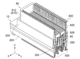
図1及び図2に示されるように、本実施の形態によるコネクタ10は、相手側コネクタ80と嵌合方向(Z方向)に沿って嵌合可能であり、且つ、電気的に接続可能である。本実施の形態によるコネクタ10及び相手側コネクタ80は、回路基板(図示せず)に夫々搭載される基板コネクタである。但し、本発明は、基板コネクタ以外のコネクタにも適用可能である。
(First embodiment)
As shown in FIGS. 1 and 2, the
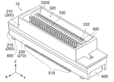
図1、図6及び図7に示されるように、コネクタ10は、絶縁性材料からなる第1ハウジング(ハウジング)200と、絶縁性材料からなる第2ハウジング(ハウジング)300と、導電性材料からなる複数のコンタクト500と、金属製の2つの固定部材600とを備えている。
As shown in FIGS. 1, 6, and 7, the
図7に示されるように、第1ハウジング200は、外壁部210と、孔部230とを有している。孔部230は、第1ハウジング200をZ方向に貫通しており、ピッチ方向(Y方向)に長く延びている。孔部230は、2つの支持部232を有している。支持部232は、孔部230のY方向における両端部に位置している。外壁部210は、XY平面において孔部230を囲んでいる。外壁部210は、Y方向に長く延びる2つの側壁部220を有している。側壁部220は、孔部230に面した内面220Sを夫々有している。側壁部220の夫々には、複数の溝部222が形成されている。溝部222の夫々は、側壁部220の内面220Sの一部を幅方向(X方向)外側に凹ませるようにして形成されている。
As shown in FIG. 7, the
図4、図5及び図7に示されるように、溝部222は、Z方向において側壁部220の上端(+Z側の端)から下端(−Z側の端)まで延びている。溝部222には、コンタクト500の一部を圧入可能な第1保持部224が形成されている(図5参照)。
As shown in FIGS. 4, 5, and 7, the
図7に示されるように、第2ハウジング300は、外壁部310と、凹部320と、凸部330と、2つの被支持部340とを有している。凹部320は、−Z方向に凹んだ凹みである。外壁部310は、凹部320を囲んでいる。凹部320は、XY平面において凸部330を囲んでいる。凸部330は、Y方向に長く延び、+Z方向に突出している。凸部330は、凹部320に面した2つの側面330Sを有している。側面330Sの夫々には、複数の溝部332が形成されている。溝部332の夫々は、側面330Sの一部をX方向内側に凹ませるようにして形成されている。
As shown in FIG. 7, the
図5に示されるように、凸部330は、中間壁336を有している。中間壁336は、X方向において凸部330の中間に位置しており、Y方向に長く延びている。溝部332は、X方向において側面330Sから中間壁336まで凹んでいる。
As shown in FIG. 5, the
図4、図5及び図7に示されるように、溝部332は、Z方向において凸部330の上端から下端まで延びている。溝部332には、コンタクト500の一部を圧入可能な第2保持部334が形成されている(図5参照)。第2保持部334は、溝部332の下端部分、且つ、中間壁336の近傍に位置している。
As shown in FIGS. 4, 5, and 7, the
図7から理解されるように、被支持部340の夫々は、外壁部310の下端から下方に(−Z方向に)延びている。図6及び図7から理解されるように、被支持部340は、XY平面において多少移動できる程度の間隔をあけて第1ハウジング200に挿入されている。詳しくは、被支持部340は、第2ハウジング300の第1ハウジング200に対する相対的な移動を許容するようにして、孔部230の支持部232に夫々部分的に受容されている。
As can be understood from FIG. 7, each of the supported
図6及び図7から理解されるように、固定部材600は、第1ハウジング200の外壁部210のY方向における両端部分に夫々取り付けられている。固定部材600は、コネクタ10が回路基板(図示せず)に搭載されるとき、回路基板に半田付け等により固定される。
As understood from FIGS. 6 and 7, the fixing
図6及び図7に示されるように、本実施の形態によるコンタクト500は、Y方向(ピッチ方向)に夫々延びる2つの列に配置されている。本実施の形態によれば、各列には、複数のコンタクト500が配置されている。
As shown in FIGS. 6 and 7, the
図8に示されるように、一方の列のコンタクト500は、他方の列のコンタクト500をZ方向と平行な軸を中心に180°回転させた形状を有している。本実施の形態によるコンタクト500は、1枚の金属板(図示せず)から打ち抜いた中間金属板(図示せず)をY方向と平行な軸を中心に折り曲げて形成されている。
As shown in FIG. 8, the
図5及び図8に示されるように、コンタクト500の夫々は、端子部510と、第1被保持部520と、連結部530と、第2被保持部540と、主部550とを有している。端子部510は、コネクタ10が回路基板(図示せず)に搭載されるとき、回路基板の信号パターン(図示せず)に接続される。第1被保持部520は、端子部510から上方に(+Z方向に)延びている。第1被保持部520は、第1ハウジング200の第1保持部224に圧入されて保持されている。連結部530は、第1被保持部520と第2被保持部540とを連結している。第2被保持部540は、連結部530から上方に延びている。第2被保持部540は、第2ハウジング300の第2保持部334に圧入されて保持されている。主部550は、第2被保持部540から延びて、第2被保持部540の上方に位置している。
As shown in FIGS. 5 and 8, each of the
図5から理解されるように、コンタクト500は、第1保持部224において第1ハウジング200に固定されており、第2保持部334において第2ハウジング300に固定されている。このため、第2ハウジング300は、コンタクト500に支持されて、Z方向及びXY平面において多少移動することができる。また、コンタクト500の主部550は、第2ハウジング300の移動に追随して移動する。即ち、本実施の形態によるコネクタ10は、フローティングコネクタである。但し、コネクタ10は、フローティングコネクタでなくてもよい。連結部530は、第1被保持部520と第2被保持部540との間を上下に(Z方向において)屈曲しつつ延びている。このため、第2ハウジング300が第1ハウジング200に対して相対的に移動した場合でも、連結部530が弾性変形して、第1被保持部520及び第2被保持部540が過度な力を受けることを防止する。
As understood from FIG. 5, the
図8に示されるように、コンタクト500の主部550は、第1バネ部560と、突出部570と、第2バネ部580とを有している。第1バネ部560及び第2バネ部580の夫々は、XZ平面において弾性変形可能である。詳しくは、第1バネ部560及び第2バネ部580の夫々は、X方向に弾性変形可能である。本実施の形態による突出部570は、第1バネ部560と第2バネ部580との境界部分に形成されている。突出部570は、第1バネ部560及び第2バネ部580の夫々から突出している。
As shown in FIG. 8, the
図5及び図8に示されるように、本実施の形態による第1バネ部560は、第1傾斜部562と第2傾斜部564とから構成されている。第1傾斜部562は、溝部332の内部を、中間壁336から離れつつ上方に延びている。第2傾斜部564は、中間壁336から更に離れつつ第1傾斜部562と交差する方向に延びている。
As shown in FIGS. 5 and 8, the
本実施の形態による第2バネ部580は、凹部320の内部を、外壁部310に接近しつつ下方に延びている。本実施の形態による第2バネ部580は、第1曲げ部582と、スライド部584と、第2曲げ部588とから構成されている。即ち、本実施の形態によるコンタクト500は、第2バネ部580の一部としてスライド部584を有している。第1曲げ部582は、下方に延びている。スライド部584は、第1曲げ部582から、外壁部310に接近しつつ下方に延びている。即ち、スライド部584は、X方向及びZ方向の双方と交差する方向に長く延びている。第2曲げ部588は、スライド部584から、下方に延びている。即ち、第1曲げ部582は、スライド部584の一方の端部からスライド部584と交差するように延びており、第2曲げ部588は、スライド部584の他方の端部からスライド部584と交差するように延びている。
The
本実施の形態によるスライド部584は、X方向及びZ方向の双方と直交する平面上を直線的に延びる狭く長い平面である(図8参照)。但し、スライド部584は、緩やかに曲がりつつ延びていてもよい。即ち、スライド部584は、概ね平坦に延びていればよい。
The
図8に示されるように、突出部570は、第1接点部(接点部)572を有しており、スライド部584は、第2接点部(接点部)586を有している。第1接点部572は、X方向において第2接点部586と異なる位置にある。本実施の形態によれば、突出部570は、第1バネ部560によって弾性的に支持されている。このため、第1接点部572は、第1バネ部560の弾性変形によって、X方向において移動量を有するように移動可能である。また、本実施の形態によれば、第2接点部586は、スライド部584の平面の一部であり、スライド部584は、第2バネ部580の一部である。このため、第2接点部586は、第2バネ部580の弾性変形によって、X方向において移動量を有するように移動可能である。更に、本実施の形態による第2接点部586は、第1バネ部560の弾性変形によっても、X方向において移動量を有するように移動可能である。
As shown in FIG. 8, the protruding
前述したように、突出部570は、第1バネ部560と第2バネ部580の間に位置している。但し、観点を変えれば、第1バネ部560の第2傾斜部564と第2バネ部580の第1曲げ部582とが突出部570を構成していると考えてもよい。即ち、突出部570は、第1バネ部560の一部と第2バネ部580の一部とから構成されていてもよい。いずれの観点によっても、第1接点部572は、第1バネ部560及び第2バネ部580から突出している。
As described above, the protruding
図9乃至図12に示されるように、相手側コネクタ80は、絶縁性材料からなる相手側ハウジング810と、導電性材料からなる複数の相手側コンタクト830とを備えている。相手側コネクタ80は、−Z方向に開口しY方向に長く延びる受容部82を有している。
As shown in FIGS. 9 to 12, the
図9、図11及び図12に示されるように、相手側ハウジング810は、外壁部812を有している。外壁部812は、Y方向に長く延びる2つの側壁部814を有している。側壁部814の夫々は、受容部82に面した内面814Sを有している。側壁部814の夫々には、複数の溝部816が形成されている。溝部816の夫々は、側壁部814の内面814Sの一部をX方向外側に凹ませるようにして形成されている。
As shown in FIGS. 9, 11, and 12, the
図9及び図10に示されるように、溝部816は、Z方向において側壁部814の+Z側の端から側壁部814のZ方向における中間部分まで延びている。溝部816には、相手側コンタクト830の一部を圧入可能な第1保持部818が形成されている(図10参照)。
As shown in FIGS. 9 and 10, the
図10乃至図12に示されるように、相手側ハウジング810には、複数の仕切り壁820が設けられている。仕切り壁820の夫々は、XZ平面と平行に延びている。詳しくは、仕切り壁820は、側壁部814の2つの内面814Sから、X方向の内側に向かって張り出しており、相手側ハウジング810のZ方向における中間部分において2つの内面814Sを連結している(図10参照)。
As shown in FIGS. 10 to 12, the
相手側ハウジング810には、複数のスリット822が形成されている。スリット822の夫々は、Y方向において2つの仕切り壁820の間に位置している。スリット822の夫々には、相手側コンタクト830の一部を圧入可能な2つの第2保持部824が形成されている(図10参照)。第2保持部824は、スリット822の+Z側の端部、且つ、側壁部814の近傍に位置している。
A plurality of
図9及び図10に示されるように、スリット822の夫々には、分離壁826が設けられている。分離壁826は、スリット822のX方向における中間部分に形成されている。分離壁826は、スリット822を2つに分離するようにしてZ方向に延びている。
As shown in FIGS. 9 and 10, a
図10乃至図12に示されるように、受容部82は、XY平面において外壁部812及び複数の仕切り壁820に囲まれている。図3に示されるように、コネクタ10と相手側コネクタ80とが互いに嵌合した嵌合状態において、外壁部812及び仕切り壁820の−Z側は、コネクタ10の凹部320に挿入され、受容部82は、コネクタ10の凸部330を受容する。このとき、コンタクト500は、相手側コンタクト830と夫々接触して電気的に接続される。
As shown in FIGS. 10 to 12, the receiving
図11及び図12に示されるように、本実施の形態による相手側コンタクト830は、Y方向に夫々延びる2つの列に配置されている。本実施の形態によれば、各列には、複数の相手側コンタクト830が配置されている。
As shown in FIGS. 11 and 12, the
図13に示されるように、一方の列の相手側コンタクト830は、他方の列の相手側コンタクト830をZ方向と平行な軸を中心に180°回転させた形状を有している。本実施の形態による相手側コンタクト830は、1枚の金属板(図示せず)から打ち抜いた中間金属板(図示せず)をY方向と平行な軸を中心に折り曲げて形成されている。
As shown in FIG. 13, the
図10及び図13に示されるように、相手側コンタクト830の夫々は、端子部832と、第1被保持部834と、連結部836と、第2被保持部838と、主部840とを有している。端子部832は、相手側コネクタ80が回路基板(図示せず)に搭載されるとき、信号パターン(図示せず)に接続される。第1被保持部834は、端子部832から−Z方向に延びている。第1被保持部834は、相手側ハウジング810の第1保持部818に圧入されて保持されている。連結部836は、第1被保持部834と第2被保持部838とを連結している。第2被保持部838は、連結部836から−Z方向に延びている。第2被保持部838は、相手側ハウジング810の第2保持部824に圧入されて保持されている。主部840は、第2被保持部838から−Z方向に更に延びている。
As shown in FIGS. 10 and 13, each of the
図8及び図13から理解されるように、本実施の形態によれば、コンタクト500の主部550と接触する部位である相手側コンタクト830の主部840は、コンタクト500の主部550と同じ形状及びサイズを有している。このため、主部840は、主部550と同様に弾性変形可能である。
As can be understood from FIGS. 8 and 13, according to the present embodiment, the
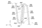
詳しくは、図13に示されるように、相手側コンタクト830の主部840は、第1バネ部842と、突出部844と、第2バネ部850とを有している。第1バネ部842及び第2バネ部850の夫々は、XZ平面において弾性変形可能である。詳しくは、第1バネ部842及び第2バネ部850の夫々は、X方向に弾性変形可能である。突出部844は、第1バネ部842及び第2バネ部850の夫々から突出している。
Specifically, as shown in FIG. 13, the
第2バネ部850は、コンタクト500の第2バネ部580(図8参照)と同様に、第1曲げ部852と、スライド部854と、第2曲げ部858とから構成されている。即ち、スライド部854は、コンタクト500のスライド部584(図8参照)と同様に、平坦に長く延びている。また、第1曲げ部852は、スライド部854の一方の端部からスライド部854と交差するように延びており、第2曲げ部858は、スライド部854の他方の端部からスライド部854と交差するように延びている。
The
図10に示されるように、第1バネ部842は、スリット822の内部を、側壁部814の内面814Sから離れつつ下方(−Z方向)に延びている。また、本実施の形態による第2バネ部850は、スリット822から受容部82に突出して、分離壁826に接近しつつ上方(+Z方向)に延びている。第2バネ部850の第2曲げ部858は、分離壁826と接触している。
As shown in FIG. 10, the
図13に示されるように、突出部844は、相手側第1接点部(相手側接点部)846を有しており、スライド部854は、相手側第2接点部(相手側接点部)856を有している。相手側第1接点部846は、X方向において相手側第2接点部856と異なる位置にある。相手側第1接点部846は、第1バネ部842の弾性変形によって、X方向において移動量を有するように移動可能である。また、相手側第2接点部856は、第2バネ部850の弾性変形によって、X方向において移動量を有するように移動可能である。更に、相手側第2接点部856は、第1バネ部842の弾性変形によっても、X方向において移動量を有するように移動可能である。
As shown in FIG. 13, the protruding
図14及び図15に示されるように、コネクタ10と相手側コネクタ80とを嵌合する場合、相手側コネクタ80は、受容部82が下方に開口した状態で、コネクタ10の上方に配置される。コネクタ10を−Z方向に沿って見たとき、コンタクト500の第1接点部572及び第2接点部586を視認可能である。また、第1接点部572は、相手側コンタクト830の相手側第1接点部846と、X方向において異なる位置にある。このため、コネクタ10と相手側コネクタ80とを嵌合する際、第1接点部572と相手側第1接点部846とは、互いに衝突しない。即ち、第1接点部572及び相手側第1接点部846の損傷を防止しつつ、第1接点部572及び相手側第1接点部846を、スライド部854及びスライド部584に夫々接触させることができる(図15参照)。
As shown in FIGS. 14 and 15, when the
図15に示されるように、コネクタ10が相手側コネクタ80と嵌合し始めた嵌合開始状態において、コンタクト500の第1接点部572は、相手側コンタクト830のスライド部854の一部と接触している。このとき、相手側コンタクト830の相手側第1接点部846は、コンタクト500のスライド部584の一部と接触している。即ち、嵌合開始状態において、コンタクト500は、相手側コンタクト830と2点で接触している。
As shown in FIG. 15, the
図17に示されるように、嵌合開始状態において、コンタクト500の第1接点部572は、相手側コンタクト830のスライド部854から接触力(FS1)を受けている。また、コンタクト500のスライド部584の一部は、相手側コンタクト830の相手側第1接点部846から接触力(FS2)を受けている。接触力(FS1)及び接触力(FS2)の夫々は、X方向外側及び下方に向かっている。
As shown in FIG. 17, the
図15及び図16から理解されるように、コネクタ10が嵌合開始状態(図15参照)から嵌合状態(図16参照)に移動するとき、コンタクト500の第1バネ部560は、中間壁336に向かって弾性変形する。第1接点部572及び第2接点部586は、第1バネ部560の弾性変形によってX方向において中間壁336に向かって移動する。このとき、第2バネ部580も、中間壁336に向かって弾性変形する。この結果、第2接点部586は、第1バネ部560の弾性変形によってX方向において移動しつつ、第2バネ部580の弾性変形によってX方向において移動する。このとき、相手側コンタクト830の相手側第1接点部846は、第1バネ部842の弾性変形によってX方向において側壁部814に向かって移動する。また、相手側第2接点部856は、第1バネ部842の弾性変形と第2バネ部850の弾性変形とによって、X方向において側壁部814に向かって移動する。
As understood from FIGS. 15 and 16, when the
嵌合開始状態から嵌合状態に移動するまでの間、相手側第1接点部846がスライド部584上を長く移動し、第1接点部572がスライド部854上を長く移動する。嵌合状態においては、相手側第1接点部846が第2接点部586に到達して、第1接点部572が相手側第2接点部856に到達する。換言すれば、嵌合状態において、第1接点部572及び第2接点部586は、相手側第2接点部856及び相手側第1接点部846と夫々接触する。即ち、コンタクト500は、嵌合状態においても相手側コンタクト830と2点で接触する。
The counterpart
図18に示されるように、コネクタ10が嵌合開始状態から嵌合状態に移動するとき、第1接点部572は、第1バネ部560の弾性変形によってX方向において第1の距離(D1)だけ移動する。このとき、第2接点部586は、第1バネ部560の弾性変形と第2バネ部580の弾性変形によってX方向において第1の距離(D1)+第2の距離(D2)だけ移動する。即ち、第2接点部586は、第2バネ部580の弾性変形によっては、第2の距離(D2)だけ移動する。第1バネ部560は、嵌合状態において比較的大きな接触力を発揮するが、嵌合時に殆ど弾性変形しない。一方、第2バネ部580は、嵌合状態において比較的小さな接触力しか発揮しないが、嵌合時に大きく弾性変形する。このため、第2の距離(D2)は、第1の距離(D1)よりも大きい。
As shown in FIG. 18, when the
上述のように、第2接点部586は、互いに機能を補完し合う2種類のバネの弾性変形によって移動するように構成されている。このため、第2接点部586は、例えば第2ハウジング300(図3参照)が相手側ハウジング810に対してX方向において相対的に移動した場合(例えば、嵌合位置がずれて−X方向又は+X方向に片寄った場合)であっても、十分な接触力により、相手側第1接点部846との接触を保つ。即ち、第2接点部586は、相手側第1接点部846と安定的に接触する。また、本実施の形態によれば、相手側第2接点部856も、第2接点部586と同様に、2種類のバネの弾性変形によって移動するように構成されている。このため、第1接点部572は、相手側第2接点部856と安定的に接触する。更に、第1接点部572又は相手側第1接点部846の位置が上下に(Z方向において)多少ずれた場合でも、第1接点部572及び第2接点部586は、相手側第2接点部856及び相手側第1接点部846と安定的に夫々接触する。本実施の形態によれば、コンタクト500と相手側コンタクト830との間の接触信頼性を高めることができる。
As described above, the
図15乃至図18から理解されるように、コネクタ10が嵌合開始状態から嵌合状態に移動するまでの間、第1接点部572は、相手側コンタクト830のスライド部854の一部から接触力を受け続けている。本実施の形態によれば、コネクタ10が嵌合開始状態から嵌合状態に移動するまでの間、接触力の方向は、スライド部854の傾きが変わるにつれて変化し続ける。嵌合状態において、第1接点部572は、相手側第2接点部856から接触力(FE1)を受ける。嵌合状態における接触力(FE1)の方向は、嵌合開始状態における接触力(FS1)の方向と異なっている。
As is understood from FIGS. 15 to 18, the
同様に、コネクタ10が嵌合開始状態から嵌合状態に移動するまでの間、スライド部584の一部は、相手側第1接点部846から接触力を受け続けている。本実施の形態によれば、コネクタ10が嵌合開始状態から嵌合状態に移動するまでの間、接触力の方向は、スライド部584の傾きが変わるにつれて変化し続ける。嵌合状態においては、スライド部584の第2接点部586が相手側第1接点部846から接触力(FE2)を受ける。嵌合状態における接触力(FE2)の方向は、嵌合開始状態における接触力(FS2)の方向と異なっている。
Similarly, a part of the
特に、本実施の形態によれば、嵌合状態における接触力(FE1)及び接触力(FE2)の夫々の方向は、Z方向とほぼ直交している。このため、嵌合状態において、相手側コネクタ80をコネクタ10から離脱させるような力が殆ど生じない。即ち、本実施の形態によれば、嵌合状態を比較的確実に維持することができる。一方、図17から理解されるように、相手側コネクタ80は、接触力による反力を利用して、コネクタ10から容易に抜去することができる。
In particular, according to the present embodiment, the respective directions of the contact force (FE1) and the contact force (FE2) in the fitted state are substantially orthogonal to the Z direction. For this reason, in a fitting state, the force which separates the
嵌合状態における接触力(FE1)及び接触力(FE2)の夫々の方向は、Z方向と直交していてもよい。更に、図19に示されるように、接触力(FE1)及び接触力(FE2)の夫々の方向が、X方向の外側及び上方に向かうように、コンタクト500及び相手側コンタクト830を変形することも可能である。
Each direction of the contact force (FE1) and the contact force (FE2) in the fitted state may be orthogonal to the Z direction. Further, as shown in FIG. 19, the
本変形例によれば、嵌合状態において、第2バネ部580の第1曲げ部582の一部が、第2バネ部850のスライド部854と第2曲げ部858との境界部分に接触する。このとき、第2バネ部580のスライド部584と第2曲げ部588との境界部分が、第2バネ部850の第1曲げ部852の一部に接触している。換言すれば、コンタクト500の第1曲げ部582は、第1接点部572′を有しており、第2曲げ部588は、第2接点部586′を有している。同様に、相手側コンタクト830の第1曲げ部852は、相手側第1接点部(相手側接点部)846′を有しており、第2曲げ部858は、相手側第2接点部(相手側接点部)856′を有している。
According to this modification, a part of the first
第1接点部572′は、嵌合状態において相手側コンタクト830の相手側第2接点部856′と接触して、相手側第2接点部856′から嵌合状態を維持するように働く接触力(FE1′)を受ける。また、第2接点部586′は、嵌合状態において相手側コンタクト830の相手側第1接点部846′と接触して、相手側第1接点部846′から嵌合状態を維持するように働く接触力(FE2′)を受ける。即ち、相手側第1接点部846′及び相手側第2接点部856′は、第2接点部586′及び第1接点部572′によって夫々ロックされており、これにより嵌合状態が維持される。
The
本実施の形態によるコネクタ10及び相手側コネクタ80は、上述した変形例に加えて、様々に変形することができる。例えば、相手側コンタクト830の主部840は、コンタクト500の主部550と異なる形状及びサイズを有していてもよい。より具体的には、相手側コンタクト830は、Z方向に沿って直線的に延びるピンコンタクトであってもよい。
The
(第2の実施の形態)
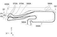
図20に示されるように、本発明の第2の実施の形態によるコネクタ10Aは、相手側コネクタ80Aと嵌合方向(X方向)に沿って嵌合可能である。
(Second Embodiment)
As shown in FIG. 20, the
コネクタ10Aは、絶縁性材料からなるハウジング400と、導電性材料からなるコンタクト500Aとを備えている。コネクタ10Aは、ピッチ方向(Y方向)に並ぶ複数のコンタクト500Aを備えていてもよい。コンタクト500Aの一部は、ハウジング400に圧入されており、これによりコンタクト500Aは、ハウジング400に保持されている。
The
本実施の形態によるコンタクト500Aは、1枚の金属板(図示せず)を打ち抜いて形成されている。このため、コンタクト500Aは、第1の実施の形態によるコンタクト500(図8参照)と比較して、より容易に形成できる。
コンタクト500Aは、第1バネ部560Aと、突出部570Aと、第2バネ部580Aと、移動部590Aとを有している。第1バネ部560Aは、移動部590Aから突出して、やや下方(−Z方向)に傾斜しつつ+X方向に長く延びている。第1バネ部560Aは、XZ平面において(詳しくは、Z方向に)弾性変形可能である。突出部570Aは、第1バネ部560Aの+X側の端部に形成されている。突出部570Aは、第1バネ部560Aから上方(+Z方向)に突出している。第2バネ部580Aは、移動部590Aから+X方向に突出した後、下方に延びている。第2バネ部580Aは、XZ平面において(詳しくは、Z方向に)弾性変形可能である。移動部590Aは、第2バネ部580Aの弾性変形によって、XZ面内を移動する(図22参照)。
The
コンタクト500Aは、スライド部584Aを更に有している。本実施の形態によるスライド部584Aは、第1バネ部560Aの上側の縁と移動部590Aの上側の縁とから構成されている。スライド部584Aは、X方向と交差する方向に概ね平坦に延びている。
The
突出部570Aは、第1接点部(接点部)572Aを有しており、スライド部584Aは、第2接点部(接点部)586Aを有している。第1接点部572Aは、突出部570Aの上端部(+Z側の端部)であり、第2接点部586Aは、スライド部584Aの縁の一部である。第1接点部572Aは、上下方向(Z方向)において第2接点部586Aと異なる位置にある。第1接点部572Aは、第1バネ部560Aの弾性変形によって、Z方向において移動量を有するように移動可能である。更に、第1接点部572Aは、第2バネ部580Aの弾性変形によっても、Z方向において移動量を有するように移動可能である。また、第2接点部586Aは、第2バネ部580Aの弾性変形によって、Z方向において移動量を有するように移動可能である。
The protruding
図20に示されるように、相手側コネクタ80Aは、絶縁性材料からなる相手側ハウジング810Aと、導電性材料からなる相手側コンタクト830Aとを備えている。相手側コンタクト830Aの一部は、相手側ハウジング810Aに圧入されており、これにより相手側コンタクト830Aは、相手側ハウジング810Aに保持されている。
As shown in FIG. 20, the
相手側コンタクト830Aは、X方向に沿って延びている。相手側コンタクト830Aは、突出部844Aと、スライド部854Aとを有している。本実施の形態による突出部844Aは、相手側コンタクト830Aの−X側の端部に形成されている。突出部844Aは、下方に突出している。本実施の形態によるスライド部854Aは、相手側コンタクト830Aの下側の縁の一部である。スライド部854Aは、X方向に延びている。
The
突出部844Aは、相手側第1接点部(相手側接点部)846Aを有しており、スライド部854Aは、相手側第2接点部(相手側接点部)856A(図22参照)を有している。相手側第1接点部846Aは、突出部844Aの下端部(−Z側の端部)であり、相手側第2接点部856Aは、スライド部854Aの縁の一部である。本実施の形態による相手側第1接点部846A及び相手側第2接点部856Aは、相手側ハウジング810Aに対して相対的に移動しない。
The protruding
図20及び図21に示されるように、コネクタ10Aと相手側コネクタ80Aとを嵌合する際、コネクタ10A及び相手側コネクタ80Aとは、X方向に沿って配置される。コネクタ10Aを−X方向に沿って見たとき、コンタクト500Aの第1接点部572A及び第2接点部586Aを視認可能である。また、第1接点部572Aは、相手側コンタクト830Aの相手側第1接点部846Aと、Z方向において異なる位置にある。このため、コネクタ10Aと相手側コネクタ80Aとを嵌合する際、第1接点部572Aと相手側第1接点部846Aとは、互いに衝突しない。
As shown in FIGS. 20 and 21, when the
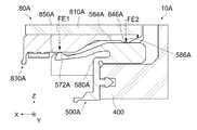
図21に示されるように、コネクタ10Aが相手側コネクタ80Aと嵌合し始めた嵌合開始状態において、コンタクト500Aの第1接点部572Aは、相手側コンタクト830Aと接触していない。一方、相手側コンタクト830Aの相手側第1接点部846Aは、コンタクト500Aのスライド部584Aの一部と接触している。嵌合開始状態において、コンタクト500Aのスライド部584Aの一部は、相手側コンタクト830Aの相手側第1接点部846Aから接触力(FS2)を受けている。接触力(FS2)は、−X方向に沿いつつ下方に向かっている。
As shown in FIG. 21, the
図21及び図22から理解されるように、コネクタ10Aが嵌合開始状態(図21参照)から嵌合状態(図22参照)に移動するまでの間、相手側第1接点部846Aがスライド部584A上を移動する。嵌合状態においては、相手側第1接点部846Aが第2接点部586Aに到達して第2接点部586Aと接触する。また、嵌合開始状態と嵌合状態との間の嵌合途中状態において、第1接点部572Aが相手側コンタクト830Aのスライド部854Aと接触する。その後、第1接点部572Aは、スライド部854A上を移動する。嵌合状態においては、第1接点部572Aが相手側第2接点部856Aに到達して相手側第2接点部856Aと接触する。即ち、コンタクト500Aは、嵌合状態において相手側コンタクト830Aと2点で接触する。
As understood from FIGS. 21 and 22, until the
図23から理解されるように、本実施の形態による第1接点部572Aは、コネクタ10Aが嵌合開始状態から嵌合状態に移動するとき、第1バネ部560Aの弾性変形によって−Z方向において移動しつつ、第2バネ部580Aの弾性変形によって+Z方向において移動する。
As can be understood from FIG. 23, the
詳しくは、嵌合開始状態における第1接点部572Aは、Z方向において初期位置(P0)に位置している。コネクタ10Aが嵌合開始状態から嵌合状態に移動するとき、仮に第1バネ部560Aが弾性変形しない場合、第1接点部572Aは、第2バネ部580Aの弾性変形によって、Z方向において初期位置(P0)から第1位置(P1)に移動する。但し、実際には第1バネ部560Aが弾性変形するため、第1接点部572Aは、Z方向において第2位置(P2)に移動する。以上の説明から理解されるように、第1接点部572Aは、第1バネ部560Aの弾性変形によっては、Z方向において第1位置(P1)と第2位置(P2)との間の距離(即ち、第1の距離(D1))だけ移動する。一方、本実施の形態による第2接点部586Aは、コネクタ10Aが嵌合開始状態から嵌合状態に移動するとき、第2バネ部580Aの弾性変形のみによってZ方向において第2の距離(D2)だけ移動する。
Specifically, the
第1バネ部560Aは、嵌合状態において比較的小さな接触力しか発揮しないが、嵌合時に大きく弾性変形する。一方、第2バネ部580Aは、嵌合状態において比較的大きな接触力を発揮するが、嵌合時に殆ど弾性変形しない。このため、第1の距離(D1)は、第2の距離(D2)よりも大きい。第1接点部572Aは、第1の実施の形態と同様に、2種類のバネの弾性変形によって移動するように構成されている。このため、第1接点部572Aと相手側第2接点部856Aとの間の接触信頼性を高めることができる。
The
図21及び図22から理解されるように、コネクタ10Aが嵌合開始状態から嵌合状態に移動するまでの間、スライド部584Aの一部は、相手側第1接点部846Aから接触力を受け続けている。嵌合状態においては、スライド部584Aの第2接点部586Aが相手側第1接点部846Aから接触力(FE2)を受ける。嵌合状態における接触力(FE2)の方向は、嵌合開始状態における接触力(FS2)の方向と異なっている。一方、第1接点部572Aは、嵌合状態において、相手側第2接点部856Aから接触力(FE1)を受ける。
As understood from FIGS. 21 and 22, a part of the
特に、本実施の形態によれば、接触力(FE1)及び接触力(FE2)の夫々の方向は、Z方向と直交している。即ち、嵌合状態において、相手側コネクタ80Aをコネクタ10Aから離脱させるような力が生じない。このため、本実施の形態によれば、第1の実施の形態と同様に、嵌合状態を比較的確実に維持することができる。更に、相手側コネクタ80Aをコネクタ10Aから容易に抜去することができる。
In particular, according to the present embodiment, the directions of the contact force (FE1) and the contact force (FE2) are orthogonal to the Z direction. That is, in the fitted state, there is no force that causes the
本実施の形態による相手側コンタクト830Aは、コンタクト500Aと異なる形状を有している。但し、相手側コンタクト830Aのうちのコンタクト500Aと接触する部位は、第1の実施の形態(図17参照)と同様に、コンタクト500Aのうちの相手側コンタクト830Aと接触する部位と同じ形状及びサイズを有していてもよい。
The
10,10A コネクタ
200 第1ハウジング(ハウジング)
210 外壁部
220 側壁部
220S 内面
222 溝部
224 第1保持部
230 孔部
232 支持部
300 第2ハウジング(ハウジング)
310 外壁部
320 凹部
330 凸部
330S 側面
332 溝部
334 第2保持部
336 中間壁
340 被支持部
400 ハウジング
500,500A コンタクト
510 端子部
520 第1被保持部
530 連結部
540 第2被保持部
550 主部
560,560A 第1バネ部
562 第1傾斜部
564 第2傾斜部
570,570A 突出部
572,572′,572A 第1接点部(接点部)
580,580A 第2バネ部
582 第1曲げ部
584,584A スライド部
586,586′,586A 第2接点部(接点部)
588 第2曲げ部
590A 移動部
600 固定部材
80,80A 相手側コネクタ
82 受容部
810,810A 相手側ハウジング
812 外壁部
814 側壁部
814S 内面
816 溝部
818 第1保持部
820 仕切り壁
822 スリット
824 第2保持部
826 分離壁
830,830A 相手側コンタクト
832 端子部
834 第1被保持部
836 連結部
838 第2被保持部
840 主部
842 第1バネ部
844,844A 突出部
846,846′,846A 相手側第1接点部(相手側接点部)
850 第2バネ部
852 第1曲げ部
854,854A スライド部
856,856′,856A 相手側第2接点部(相手側接点部)
858 第2曲げ部
10,
210
310
580, 580A
588
850
858 2nd bending part
Claims (9)
前記コンタクトは、突出部と、第1バネ部と、スライド部と、第2バネ部とを有しており、
前記突出部は、前記第1バネ部から突出しており、且つ、第1接点部を有しており、
前記第1接点部は、前記第1バネ部の弾性変形によって、前記嵌合方向と直交する所定方向において移動量を有するように移動可能であり、前記嵌合状態において前記相手側コンタクトと接触し、
前記スライド部は、平坦に延びており、且つ、第2接点部を有しており、
前記第2接点部は、前記第2バネ部の弾性変形によって、前記所定方向において移動量を有するように移動可能であり、
前記コネクタが前記相手側コネクタと嵌合し始めた嵌合開始状態から前記嵌合状態に移動するまでの間、前記相手側コンタクトの一部である相手側接点部が前記スライド部上を移動し、前記嵌合状態においては、前記相手側接点部が前記第2接点部に到達し、
前記コネクタが前記嵌合開始状態から前記嵌合状態に移動するとき、前記第1接点部及び前記第2接点部のうちの一方は、前記第1バネ部の弾性変形によって前記所定方向において移動しつつ、前記第2バネ部の弾性変形によって前記所定方向において移動する
コネクタ。 A connector that can be mated with a mating connector provided with a mating contact along a mating direction, and includes a contact that contacts the mating contact at two points in a mated state mated with the mating connector. And
The contact has a protruding portion, a first spring portion, a slide portion, and a second spring portion,
The protruding portion protrudes from the first spring portion and has a first contact portion,
The first contact portion is movable by an elastic deformation of the first spring portion so as to have a movement amount in a predetermined direction orthogonal to the fitting direction, and contacts the counterpart contact in the fitted state. ,
The slide portion extends flat and has a second contact portion,
The second contact portion is movable so as to have a moving amount in the predetermined direction by elastic deformation of the second spring portion,
The mating contact portion, which is a part of the mating contact, moves on the slide portion until the connector moves from the mating start state where the connector starts mating with the mating connector to the mating state. In the fitted state, the counterpart contact portion reaches the second contact portion,
When the connector moves from the fitting start state to the fitting state, one of the first contact portion and the second contact portion moves in the predetermined direction by elastic deformation of the first spring portion. However, the connector moves in the predetermined direction by elastic deformation of the second spring portion.
前記コネクタが前記嵌合開始状態から前記嵌合状態に移動するとき、前記第1接点部は、前記第1バネ部の前記弾性変形によって前記所定方向において第1の距離だけ移動し、前記第2接点部は、前記第2バネ部の前記弾性変形によって前記所定方向において第2の距離だけ移動し、
前記第2の距離は前記第1の距離よりも大きい
コネクタ。 The connector according to claim 1,
When the connector moves from the fitting start state to the fitting state, the first contact portion moves by a first distance in the predetermined direction by the elastic deformation of the first spring portion, and the second The contact portion moves by a second distance in the predetermined direction by the elastic deformation of the second spring portion,
The connector wherein the second distance is greater than the first distance.
前記コネクタが前記嵌合開始状態から前記嵌合状態に移動するとき、前記第1接点部は、前記第1バネ部の前記弾性変形によって前記所定方向において第1の距離だけ移動し、前記第2接点部は、前記第2バネ部の前記弾性変形によって前記所定方向において第2の距離だけ移動し、
前記第1の距離は前記第2の距離よりも大きい
コネクタ。 The connector according to claim 1,
When the connector moves from the fitting start state to the fitting state, the first contact portion moves by a first distance in the predetermined direction by the elastic deformation of the first spring portion, and the second The contact portion moves by a second distance in the predetermined direction by the elastic deformation of the second spring portion,
The first distance is a connector that is larger than the second distance.
前記第1接点部は、前記所定方向において前記第2接点部と異なる位置にあり、
前記コネクタを前記嵌合方向に沿って見たとき、前記第1接点部及び前記第2接点部を視認可能である
コネクタ。 The connector according to any one of claims 1 to 3,
The first contact portion is at a position different from the second contact portion in the predetermined direction,
The connector which can visually recognize the 1st contact part and the 2nd contact part when the connector is seen along the fitting direction.
前記コネクタが前記嵌合開始状態から前記嵌合状態に移動するまでの間、前記スライド部の一部は、前記相手側接点部から接触力を受け続けており、前記嵌合状態においては、前記スライド部の前記第2接点部が前記接触力を受け、
前記嵌合状態における前記接触力の方向は、前記嵌合開始状態における前記接触力の方向と異なっている
コネクタ。 The connector according to any one of claims 1 to 4,
Until the connector moves from the fitting start state to the fitting state, a part of the slide portion continues to receive a contact force from the mating contact portion. The second contact portion of the slide portion receives the contact force;
The connector in which the direction of the contact force in the fitted state is different from the direction of the contact force in the fitted start state.
前記嵌合状態における前記接触力の方向は、前記嵌合方向と直交している
コネクタ。 The connector according to claim 5, wherein
The connector in which the direction of the contact force in the fitted state is orthogonal to the fitting direction.
前記嵌合状態において、前記第1接点部は前記相手側コンタクトから第1接触力を受けており、前記第2接点部は前記相手側コンタクトから第2接触力を受けており、
前記第1接触力及び前記第2接触力の方向は、前記嵌合方向と直交している
コネクタ。 The connector according to any one of claims 1 to 4,
In the fitted state, the first contact portion receives a first contact force from the counterpart contact, and the second contact portion receives a second contact force from the counterpart contact,
A connector in which directions of the first contact force and the second contact force are orthogonal to the fitting direction.
前記コンタクトは、1枚の金属板を打ち抜いて形成されている
コネクタ。 The connector according to any one of claims 1 to 7,
The contact is a connector formed by punching a single metal plate.
前記コンタクトは、第1バネ部と、第2バネ部とを有しており、
前記第2バネ部は、第1曲げ部と、スライド部と、第2曲げ部とを有しており、
前記スライド部は、平坦に延びており、
前記第1曲げ部は、前記スライド部の一方の端部から前記スライド部と交差するように延びており、且つ、第1接点部を有しており、
前記第2曲げ部は、前記スライド部の他方の端部から前記スライド部と交差するように延びており、且つ、第2接点部を有しており、
前記第1接点部は、前記第1バネ部の弾性変形によって、前記嵌合方向と直交する所定方向において移動量を有するように移動可能であり、前記嵌合状態において前記相手側コンタクトと接触して前記相手側コンタクトから前記嵌合状態を維持するように働く接触力を受けており、
前記第2接点部は、前記第2バネ部の弾性変形によって、前記所定方向において移動量を有するように移動可能であり、前記嵌合状態において前記相手側コンタクトと接触して前記相手側コンタクトから前記嵌合状態を維持するように働く他の接触力を受けており、
前記コネクタが前記相手側コネクタと嵌合し始めた嵌合開始状態から前記嵌合状態に移動するとき、前記第2接点部は、前記第1バネ部の弾性変形によって前記所定方向において移動しつつ、前記第2バネ部の弾性変形によって前記所定方向において移動する
コネクタ。 A connector that can be mated with a mating connector provided with a mating contact along a mating direction, and includes a contact that contacts the mating contact at two points in a mated state mated with the mating connector. And
The contact has a first spring part and a second spring part,
The second spring part has a first bent part, a slide part, and a second bent part,
The slide portion extends flatly,
The first bent portion extends from one end portion of the slide portion so as to intersect the slide portion, and has a first contact portion,
The second bent portion extends from the other end of the slide portion so as to intersect the slide portion, and has a second contact portion,
The first contact portion is movable by an elastic deformation of the first spring portion so as to have a movement amount in a predetermined direction orthogonal to the fitting direction, and contacts the counterpart contact in the fitted state. Receiving the contact force that works to maintain the fitted state from the counterpart contact
The second contact portion is movable so as to have a moving amount in the predetermined direction by elastic deformation of the second spring portion, and in contact with the counterpart contact in the fitted state, Receiving other contact forces that work to maintain the mated state;
When the connector moves from the fitting start state where the connector starts to be fitted to the mating connector to the fitting state, the second contact portion is moved in the predetermined direction by elastic deformation of the first spring portion. A connector that moves in the predetermined direction by elastic deformation of the second spring portion.
Priority Applications (4)
| Application Number | Priority Date | Filing Date | Title |
|---|---|---|---|
| JP2013164975A JP6084133B2 (en) | 2013-08-08 | 2013-08-08 | connector |
| TW103123427A TWI505581B (en) | 2013-08-08 | 2014-07-08 | Connector |
| US14/331,884 US9252517B2 (en) | 2013-08-08 | 2014-07-15 | Connector |
| CN201410385471.9A CN104347971B (en) | 2013-08-08 | 2014-08-07 | Adapter |
Applications Claiming Priority (1)
| Application Number | Priority Date | Filing Date | Title |
|---|---|---|---|
| JP2013164975A JP6084133B2 (en) | 2013-08-08 | 2013-08-08 | connector |
Publications (3)
| Publication Number | Publication Date |
|---|---|
| JP2015035300A JP2015035300A (en) | 2015-02-19 |
| JP2015035300A5 JP2015035300A5 (en) | 2016-06-02 |
| JP6084133B2 true JP6084133B2 (en) | 2017-02-22 |
Family
ID=52449029
Family Applications (1)
| Application Number | Title | Priority Date | Filing Date |
|---|---|---|---|
| JP2013164975A Active JP6084133B2 (en) | 2013-08-08 | 2013-08-08 | connector |
Country Status (4)
| Country | Link |
|---|---|
| US (1) | US9252517B2 (en) |
| JP (1) | JP6084133B2 (en) |
| CN (1) | CN104347971B (en) |
| TW (1) | TWI505581B (en) |
Cited By (1)
| Publication number | Priority date | Publication date | Assignee | Title |
|---|---|---|---|---|
| US10797422B2 (en) | 2018-10-09 | 2020-10-06 | Japan Aviation Electronics Industry, Limited | Connector |
Families Citing this family (9)
| Publication number | Priority date | Publication date | Assignee | Title |
|---|---|---|---|---|
| JP2015038831A (en) * | 2013-08-19 | 2015-02-26 | 富士通コンポーネント株式会社 | Plug connector, jack connector, and connector device |
| JP6537890B2 (en) * | 2014-09-26 | 2019-07-03 | 日本航空電子工業株式会社 | connector |
| JP6270294B1 (en) * | 2016-11-24 | 2018-01-31 | イリソ電子工業株式会社 | Movable connector |
| US20220264854A1 (en) * | 2017-11-13 | 2022-08-25 | Beewise Technologies Ltd. | Autonomous beehives |
| JP7197995B2 (en) * | 2018-04-26 | 2022-12-28 | ヒロセ電機株式会社 | electrical connector for circuit board |
| JP7109303B2 (en) * | 2018-08-07 | 2022-07-29 | 日本航空電子工業株式会社 | connector assembly |
| JP7297622B2 (en) * | 2019-09-20 | 2023-06-26 | 日本航空電子工業株式会社 | floating connector |
| TWI753658B (en) * | 2020-11-16 | 2022-01-21 | 禾昌興業股份有限公司 | Floating connector with power electrode structure |
| US11831093B2 (en) * | 2021-03-30 | 2023-11-28 | Cisco Technology, Inc. | Socket locator |
Family Cites Families (12)
| Publication number | Priority date | Publication date | Assignee | Title |
|---|---|---|---|---|
| JPS6361774U (en) | 1986-10-09 | 1988-04-23 | ||
| JP3350843B2 (en) * | 1996-12-20 | 2002-11-25 | モレックス インコーポレーテッド | Method of manufacturing electrical connector with insert mold |
| JPH11297435A (en) * | 1998-04-14 | 1999-10-29 | Toshiba Corp | Connector device, circuit module having the connector device, and electronic device equipped with the circuit module |
| CA2351283A1 (en) * | 2001-06-22 | 2002-12-22 | Fci Americas Technology, Inc. | Connector assembly comprising a tab-receiving insulated spring sleeve and a dual contact pairs of spaced apart contact members and tails |
| JP2006012625A (en) * | 2004-06-25 | 2006-01-12 | Smk Corp | Board to board connector |
| JP4143092B2 (en) | 2005-02-23 | 2008-09-03 | 日本航空電子工業株式会社 | connector |
| JP4190019B2 (en) | 2006-09-12 | 2008-12-03 | 日本航空電子工業株式会社 | connector |
| JP4967771B2 (en) * | 2007-04-11 | 2012-07-04 | オムロン株式会社 | Contacts and connectors |
| JP2009037970A (en) | 2007-08-03 | 2009-02-19 | Taiko Denki Co Ltd | Socket and connector |
| JP4804526B2 (en) * | 2008-11-28 | 2011-11-02 | ヒロセ電機株式会社 | Electrical connector |
| JP2010272320A (en) | 2009-05-20 | 2010-12-02 | Fujitsu Component Ltd | Connector device |
| JP5090506B2 (en) * | 2010-08-18 | 2012-12-05 | 日本航空電子工業株式会社 | connector |
-
2013
- 2013-08-08 JP JP2013164975A patent/JP6084133B2/en active Active
-
2014
- 2014-07-08 TW TW103123427A patent/TWI505581B/en active
- 2014-07-15 US US14/331,884 patent/US9252517B2/en active Active
- 2014-08-07 CN CN201410385471.9A patent/CN104347971B/en active Active
Cited By (1)
| Publication number | Priority date | Publication date | Assignee | Title |
|---|---|---|---|---|
| US10797422B2 (en) | 2018-10-09 | 2020-10-06 | Japan Aviation Electronics Industry, Limited | Connector |
Also Published As
| Publication number | Publication date |
|---|---|
| CN104347971B (en) | 2016-08-17 |
| CN104347971A (en) | 2015-02-11 |
| TWI505581B (en) | 2015-10-21 |
| US20150044919A1 (en) | 2015-02-12 |
| US9252517B2 (en) | 2016-02-02 |
| TW201526420A (en) | 2015-07-01 |
| JP2015035300A (en) | 2015-02-19 |
Similar Documents
| Publication | Publication Date | Title |
|---|---|---|
| JP6084133B2 (en) | connector | |
| JP6553843B2 (en) | connector | |
| JP6591251B2 (en) | connector | |
| JP5606588B1 (en) | connector | |
| JP6446109B1 (en) | connector | |
| JP6116056B2 (en) | connector | |
| JP6249676B2 (en) | Electrical connector | |
| JP5964673B2 (en) | Electrical connector and female terminal | |
| US20150222046A1 (en) | Electrical Connector | |
| JP5956071B2 (en) | Connecting terminal | |
| JP6227225B2 (en) | connector | |
| JP2016146255A (en) | Socket type connector and connector unit | |
| JP2016062836A (en) | Connection structure of connector terminal | |
| JP5748378B2 (en) | Connector and contact used for it | |
| US9912089B2 (en) | Electrical connector having a female terminal with a holding protrusion | |
| JP2024052802A (en) | Movable connector and shield manufacturing method | |
| JP5866129B2 (en) | Pair of mating electrical connectors | |
| JP2012243676A (en) | Connector | |
| JP6483497B2 (en) | connector | |
| EP2575215B1 (en) | Terminal fitting | |
| EP2750253A1 (en) | Connector | |
| JP6309429B2 (en) | Contacts and connectors | |
| JP2018181468A (en) | Connector | |
| JP2018116825A (en) | connector | |
| WO2014007042A1 (en) | Joint terminal |
Legal Events
| Date | Code | Title | Description |
|---|---|---|---|
| A521 | Request for written amendment filed |
Free format text: JAPANESE INTERMEDIATE CODE: A523 Effective date: 20160408 |
|
| A621 | Written request for application examination |
Free format text: JAPANESE INTERMEDIATE CODE: A621 Effective date: 20160408 |
|
| A977 | Report on retrieval |
Free format text: JAPANESE INTERMEDIATE CODE: A971007 Effective date: 20161227 |
|
| TRDD | Decision of grant or rejection written | ||
| A01 | Written decision to grant a patent or to grant a registration (utility model) |
Free format text: JAPANESE INTERMEDIATE CODE: A01 Effective date: 20170104 |
|
| A61 | First payment of annual fees (during grant procedure) |
Free format text: JAPANESE INTERMEDIATE CODE: A61 Effective date: 20170124 |
|
| R150 | Certificate of patent or registration of utility model |
Ref document number: 6084133 Country of ref document: JP Free format text: JAPANESE INTERMEDIATE CODE: R150 |
|
| R250 | Receipt of annual fees |
Free format text: JAPANESE INTERMEDIATE CODE: R250 |
|
| R250 | Receipt of annual fees |
Free format text: JAPANESE INTERMEDIATE CODE: R250 |
|
| R250 | Receipt of annual fees |
Free format text: JAPANESE INTERMEDIATE CODE: R250 |
|
| R250 | Receipt of annual fees |
Free format text: JAPANESE INTERMEDIATE CODE: R250 |
|
| R250 | Receipt of annual fees |
Free format text: JAPANESE INTERMEDIATE CODE: R250 |