JP7348090B2 - connector assembly - Google Patents
connector assembly Download PDFInfo
- Publication number
- JP7348090B2 JP7348090B2 JP2020009806A JP2020009806A JP7348090B2 JP 7348090 B2 JP7348090 B2 JP 7348090B2 JP 2020009806 A JP2020009806 A JP 2020009806A JP 2020009806 A JP2020009806 A JP 2020009806A JP 7348090 B2 JP7348090 B2 JP 7348090B2
- Authority
- JP
- Japan
- Prior art keywords
- connector
- outer member
- locking surface
- inner structure
- connector assembly
- Prior art date
- Legal status (The legal status is an assumption and is not a legal conclusion. Google has not performed a legal analysis and makes no representation as to the accuracy of the status listed.)
- Active
Links
Images


Classifications
-
- H—ELECTRICITY
- H01—ELECTRIC ELEMENTS
- H01R—ELECTRICALLY-CONDUCTIVE CONNECTIONS; STRUCTURAL ASSOCIATIONS OF A PLURALITY OF MUTUALLY-INSULATED ELECTRICAL CONNECTING ELEMENTS; COUPLING DEVICES; CURRENT COLLECTORS
- H01R13/00—Details of coupling devices of the kinds covered by groups H01R12/70 or H01R24/00 - H01R33/00
- H01R13/62—Means for facilitating engagement or disengagement of coupling parts or for holding them in engagement
- H01R13/627—Snap or like fastening
- H01R13/6271—Latching means integral with the housing
- H01R13/6272—Latching means integral with the housing comprising a single latching arm
-
- H—ELECTRICITY
- H01—ELECTRIC ELEMENTS
- H01R—ELECTRICALLY-CONDUCTIVE CONNECTIONS; STRUCTURAL ASSOCIATIONS OF A PLURALITY OF MUTUALLY-INSULATED ELECTRICAL CONNECTING ELEMENTS; COUPLING DEVICES; CURRENT COLLECTORS
- H01R13/00—Details of coupling devices of the kinds covered by groups H01R12/70 or H01R24/00 - H01R33/00
- H01R13/62—Means for facilitating engagement or disengagement of coupling parts or for holding them in engagement
- H01R13/627—Snap or like fastening
- H01R13/6271—Latching means integral with the housing
-
- H—ELECTRICITY
- H01—ELECTRIC ELEMENTS
- H01R—ELECTRICALLY-CONDUCTIVE CONNECTIONS; STRUCTURAL ASSOCIATIONS OF A PLURALITY OF MUTUALLY-INSULATED ELECTRICAL CONNECTING ELEMENTS; COUPLING DEVICES; CURRENT COLLECTORS
- H01R13/00—Details of coupling devices of the kinds covered by groups H01R12/70 or H01R24/00 - H01R33/00
- H01R13/62—Means for facilitating engagement or disengagement of coupling parts or for holding them in engagement
- H01R13/627—Snap or like fastening
-
- H—ELECTRICITY
- H01—ELECTRIC ELEMENTS
- H01R—ELECTRICALLY-CONDUCTIVE CONNECTIONS; STRUCTURAL ASSOCIATIONS OF A PLURALITY OF MUTUALLY-INSULATED ELECTRICAL CONNECTING ELEMENTS; COUPLING DEVICES; CURRENT COLLECTORS
- H01R13/00—Details of coupling devices of the kinds covered by groups H01R12/70 or H01R24/00 - H01R33/00
- H01R13/46—Bases; Cases
- H01R13/502—Bases; Cases composed of different pieces
-
- H—ELECTRICITY
- H01—ELECTRIC ELEMENTS
- H01R—ELECTRICALLY-CONDUCTIVE CONNECTIONS; STRUCTURAL ASSOCIATIONS OF A PLURALITY OF MUTUALLY-INSULATED ELECTRICAL CONNECTING ELEMENTS; COUPLING DEVICES; CURRENT COLLECTORS
- H01R13/00—Details of coupling devices of the kinds covered by groups H01R12/70 or H01R24/00 - H01R33/00
- H01R13/62—Means for facilitating engagement or disengagement of coupling parts or for holding them in engagement
- H01R13/629—Additional means for facilitating engagement or disengagement of coupling parts, e.g. aligning or guiding means, levers, gas pressure electrical locking indicators, manufacturing tolerances
- H01R13/631—Additional means for facilitating engagement or disengagement of coupling parts, e.g. aligning or guiding means, levers, gas pressure electrical locking indicators, manufacturing tolerances for engagement only
- H01R13/6315—Additional means for facilitating engagement or disengagement of coupling parts, e.g. aligning or guiding means, levers, gas pressure electrical locking indicators, manufacturing tolerances for engagement only allowing relative movement between coupling parts, e.g. floating connection
-
- H—ELECTRICITY
- H01—ELECTRIC ELEMENTS
- H01R—ELECTRICALLY-CONDUCTIVE CONNECTIONS; STRUCTURAL ASSOCIATIONS OF A PLURALITY OF MUTUALLY-INSULATED ELECTRICAL CONNECTING ELEMENTS; COUPLING DEVICES; CURRENT COLLECTORS
- H01R13/00—Details of coupling devices of the kinds covered by groups H01R12/70 or H01R24/00 - H01R33/00
- H01R13/62—Means for facilitating engagement or disengagement of coupling parts or for holding them in engagement
- H01R13/639—Additional means for holding or locking coupling parts together, after engagement, e.g. separate keylock, retainer strap
-
- H—ELECTRICITY
- H01—ELECTRIC ELEMENTS
- H01R—ELECTRICALLY-CONDUCTIVE CONNECTIONS; STRUCTURAL ASSOCIATIONS OF A PLURALITY OF MUTUALLY-INSULATED ELECTRICAL CONNECTING ELEMENTS; COUPLING DEVICES; CURRENT COLLECTORS
- H01R24/00—Two-part coupling devices, or either of their cooperating parts, characterised by their overall structure
- H01R24/005—Two-part coupling devices, or either of their cooperating parts, characterised by their overall structure requiring successive relative motions to complete the coupling, e.g. bayonet type
-
- H—ELECTRICITY
- H01—ELECTRIC ELEMENTS
- H01R—ELECTRICALLY-CONDUCTIVE CONNECTIONS; STRUCTURAL ASSOCIATIONS OF A PLURALITY OF MUTUALLY-INSULATED ELECTRICAL CONNECTING ELEMENTS; COUPLING DEVICES; CURRENT COLLECTORS
- H01R13/00—Details of coupling devices of the kinds covered by groups H01R12/70 or H01R24/00 - H01R33/00
- H01R13/46—Bases; Cases
- H01R13/502—Bases; Cases composed of different pieces
- H01R13/506—Bases; Cases composed of different pieces assembled by snap action of the parts
-
- H—ELECTRICITY
- H01—ELECTRIC ELEMENTS
- H01R—ELECTRICALLY-CONDUCTIVE CONNECTIONS; STRUCTURAL ASSOCIATIONS OF A PLURALITY OF MUTUALLY-INSULATED ELECTRICAL CONNECTING ELEMENTS; COUPLING DEVICES; CURRENT COLLECTORS
- H01R13/00—Details of coupling devices of the kinds covered by groups H01R12/70 or H01R24/00 - H01R33/00
- H01R13/64—Means for preventing incorrect coupling
- H01R13/641—Means for preventing incorrect coupling by indicating incorrect coupling; by indicating correct or full engagement
Description
本発明は、互いに嵌合可能な第1コネクタと第2コネクタとを備えるコネクタ組立体に関する。 The present invention relates to a connector assembly including a first connector and a second connector that can be fitted into each other.
このタイプのコネクタ組立体は、例えば、特許文献1に開示されている。
This type of connector assembly is disclosed, for example, in
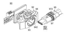
図17及び図18を参照すると、特許文献1には、前後方向に沿って互いに嵌合可能な第1コネクタ92と第2コネクタ95とを備えるコネクタ組立体90が開示されている。第1コネクタ92は、第1コネクタ本体932を含む内側構造体93と、内側構造体93に取付けられた外側部材94とを備えている。第2コネクタ95は、第2コネクタ本体962を含む内側構造体96と、内側構造体96に取付けられた外側部材97とを備えている。第1コネクタ92の外側部材94には、ロック突起942が形成されている。第2コネクタ95の外側部材97には、ロック溝972が形成されている。
Referring to FIGS. 17 and 18,
図18を参照すると、第1コネクタ92と第2コネクタ95とが互いに嵌合した嵌合状態にあるとき、第2コネクタ本体962は、第1コネクタ本体932の内部に部分的に挿入されており、これにより、第1コネクタ92と第2コネクタ95とは、互いに電気的に接続されている。嵌合状態において、ロック突起942は、ロック溝972に受容されており、これにより嵌合状態がロックされている。
Referring to FIG. 18, when the
特許文献1のようなコネクタ組立体において、第2コネクタは、嵌合状態がロックされるまで、嵌合方向(前後方向)に沿って第1コネクタに挿入する必要がある。この挿入の際、嵌合状態がロックされる前に、第2コネクタ本体の先端が第1コネクタ本体の奥側の部位(奥側部)に突き当たる場合がある。この場合、嵌合状態がロックされたとき、第1コネクタ本体の先端が第2コネクタ本体の奥側部に押し付けられて破損する可能性がある。即ち、従来技術によれば、第1コネクタを第2コネクタと嵌合する際に、コネクタ本体(第1コネクタ本体及び/又は第2コネクタ本体)が破損するおそれがある。
In a connector assembly like
そこで、本発明は、第1コネクタを第2コネクタと嵌合する際のコネクタ本体の破損を防止可能なコネクタ組立体を提供することを目的とする。 SUMMARY OF THE INVENTION Therefore, an object of the present invention is to provide a connector assembly that can prevent damage to the connector body when fitting a first connector to a second connector.
従来のコネクタ組立体によれば、第2コネクタを第1コネクタに嵌合する際、第1コネクタの外側部材が第2コネクタの外側部材と突き当たるか、又は、第1コネクタの内側構造体が第2コネクタの内側構造体と突き当たるまで、第2コネクタの前後方向に沿った移動を許容し、これにより嵌合状態のロックを可能にしていた。このようなコネクタ組立体によれば、第1コネクタ及び第2コネクタの様々な部材における公差に起因して、第1コネクタのコネクタ本体が第2コネクタのコネクタ本体に押し付けられるおそれがある。理論的には、公差を実質的になくすことで問題を解決できる。しかしながら、製造コストを考慮すると、そのような解決方法は現実的ではない。 According to conventional connector assemblies, when mating the second connector to the first connector, the outer member of the first connector abuts the outer member of the second connector, or the inner structure of the first connector abuts the outer member of the second connector. The second connector is allowed to move in the front-rear direction until it abuts against the inner structure of the second connector, thereby locking the fitted state. According to such a connector assembly, the connector body of the first connector may be pressed against the connector body of the second connector due to tolerances in various members of the first connector and the second connector. In theory, the problem could be solved by virtually eliminating tolerances. However, considering manufacturing costs, such a solution is not practical.
本発明の発明者は、以上のような考察に基づき、第1コネクタの外側部材と第2コネクタの内側構造体とが互いに突き当たるまで第2コネクタの前後方向に沿った移動を許容しつつ、第1コネクタの外側部材と第2コネクタの外側部材とによって嵌合状態をロックするという構造を創作した。この構造を有する本発明のコネクタ組立体によれば、公差を許容しつつコネクタ本体の破損を防止できる。具体的には、本発明は、以下のコネクタ組立体を提供する。 Based on the above considerations, the inventors of the present invention have proposed that while allowing the second connector to move in the front-rear direction until the outer member of the first connector and the inner structure of the second connector abut each other, We created a structure in which the fitted state is locked by the outer member of the first connector and the outer member of the second connector. According to the connector assembly of the present invention having this structure, damage to the connector body can be prevented while allowing tolerances. Specifically, the present invention provides the following connector assembly.
本発明は、第1のコネクタ組立体として、
第1コネクタと第2コネクタとを備えるコネクタ組立体であって、
前記第2コネクタは、前後方向において前方に位置する第1コネクタと前記前後方向に沿って嵌合可能であり、
前記第1コネクタは、第1内側構造体と、第1外側部材とを備えており、
前記第1内側構造体は、第1コネクタ本体を備えており、
前記第1外側部材は、前記第1内側構造体に取り付けられており、
前記第1外側部材は、第1ロック面と、第1規制部と、第1突当部とを有しており、
前記第1ロック面は、前方に向いており、
前記第1規制部は、後方に向いており、
前記第1突当部は、後方に向いており、
前記第2コネクタは、第2内側構造体と、第2外側部材とを備えており、
前記第2内側構造体は、第2コネクタ本体と、第2突当部とを備えており、
前記第2コネクタ本体は、前記第1コネクタと前記第2コネクタとが互いに嵌合した嵌合状態において、前記第1コネクタ本体と接続され、
前記第2突当部は、前方に向いており、
前記第2突当部は、前記第2コネクタが前記第1コネクタと嵌合するとき、前記第1突当部に突き当たり、
前記第2外側部材は、前記第2内側構造体に取り付けられており、
前記第2外側部材は、第2ロック面と、第2規制部とを有しており、
前記第2ロック面は、後方に向いており、
前記嵌合状態において、前記第2ロック面は、前記第1ロック面と前記前後方向において対向しており、前記第2コネクタの前記第1コネクタに対する後方への相対移動を規制しており、
前記第2規制部は、前方に向いており、
前記嵌合状態において、前記第2規制部は、前記第1規制部と前記前後方向において対向しており、前記第2コネクタの前記第1コネクタに対する前方への相対移動を規制しており、
前記第1規制部と前記第1ロック面とは、前記前後方向において第1距離だけ互いに離れており、
前記第2規制部と前記第2ロック面とは、前記前後方向において第2距離だけ互いに離れており、
前記第1規制部が前記第1ロック面の前方に位置している場合、前記第1距離は、前記第2距離よりも長く、
前記第1規制部が前記第1ロック面の後方に位置している場合、前記第1距離は、前記第2距離よりも短く、
前記嵌合状態において、前記第2外側部材は、前記第1外側部材に対して前記前後方向に沿って相対的に移動可能である
コネクタ組立体を提供する。
The present invention provides, as a first connector assembly,
A connector assembly comprising a first connector and a second connector,
The second connector can be fitted along the front-back direction with the first connector located at the front in the front-back direction,
The first connector includes a first inner structure and a first outer member,
The first inner structure includes a first connector body,
the first outer member is attached to the first inner structure,
The first outer member has a first locking surface, a first regulating part, and a first abutting part,
the first locking surface faces forward;
The first regulating portion faces rearward;
The first abutting portion faces rearward,
The second connector includes a second inner structure and a second outer member,
The second inner structure includes a second connector main body and a second abutting portion,
The second connector body is connected to the first connector body in a fitted state in which the first connector and the second connector are fitted to each other,
the second abutting portion faces forward;
the second abutting portion abuts against the first abutting portion when the second connector is fitted with the first connector;
the second outer member is attached to the second inner structure,
The second outer member has a second locking surface and a second regulating portion,
the second locking surface faces rearward;
In the fitted state, the second locking surface faces the first locking surface in the front-rear direction, and restricts rearward relative movement of the second connector with respect to the first connector;
the second regulating portion faces forward;
In the fitted state, the second restriction part faces the first restriction part in the front-rear direction, and restricts forward relative movement of the second connector with respect to the first connector;
The first restricting portion and the first locking surface are separated from each other by a first distance in the front-rear direction,
The second restricting portion and the second locking surface are separated from each other by a second distance in the front-rear direction,
when the first restriction part is located in front of the first locking surface, the first distance is longer than the second distance;
When the first restriction part is located behind the first locking surface, the first distance is shorter than the second distance,
In the fitted state, the second outer member provides a connector assembly that is movable relative to the first outer member along the front-back direction.
本発明は、第2のコネクタ組立体として、第1のコネクタ組立体であって、
前記第2内側構造体は、前記第2外側部材に対して前記前後方向に沿って所定距離だけ相対的に移動可能となるように、前記第2外側部材に保持されている
コネクタ組立体を提供する。
The present invention provides a first connector assembly as a second connector assembly, comprising:
The second inner structure provides a connector assembly held by the second outer member so as to be movable relative to the second outer member by a predetermined distance along the front-rear direction. do.
本発明は、第3のコネクタ組立体として、第1又は第2のコネクタ組立体であって、
前記第1コネクタ本体は、対向部を有しており、
前記第2コネクタ本体は、先端部を有しており、
前記嵌合状態において、前記対向部と前記先端部とは、前記前後方向において互いに離れており且つ対向している
コネクタ組立体を提供する。
The present invention provides a first or second connector assembly as a third connector assembly, comprising:
The first connector body has a facing portion,
The second connector body has a tip,
In the fitted state, the facing portion and the tip end portion provide a connector assembly that is spaced apart from and opposed to each other in the front-rear direction.
本発明は、第4のコネクタ組立体として、第3のコネクタ組立体であって、
前記第2コネクタが前記第1コネクタと嵌合する際、前記第2コネクタ本体は、前記第1コネクタ本体に受容される
コネクタ組立体を提供する。
The present invention provides a third connector assembly as a fourth connector assembly, comprising:
When the second connector is mated with the first connector, the second connector body provides a connector assembly that is received by the first connector body.
本発明は、第5のコネクタ組立体として、第1から第4までのいずれかのコネクタ組立体であって、
前記第2外側部材の前端は、前記第2コネクタ本体の前端の前方に位置している
コネクタ組立体を提供する。
As a fifth connector assembly, the present invention provides any one of the first to fourth connector assemblies,
The front end of the second outer member provides a connector assembly located forward of the front end of the second connector body.
本発明は、第6のコネクタ組立体として、第1から第5までのいずれかのコネクタ組立体であって、
前記第1外側部材は、第1外周部を有しており、
前記第1外周部は、前記前後方向と直交する直交平面において、少なくとも部分的に隙間空間を挟んで前記第1突当部の外側に位置しており、
前記第2外側部材は、第2外周部を有しており、
前記第2外周部は、前記直交平面において、前記第2コネクタ本体を覆っており、
前記嵌合状態において、前記第2外周部は、少なくとも部分的に前記第1外周部の前記直交平面における内側に位置しており、且つ、少なくとも部分的に前記隙間空間の内部に位置している
コネクタ組立体を提供する。
The present invention, as a sixth connector assembly, is any one of the first to fifth connector assemblies,
The first outer member has a first outer peripheral portion,
The first outer circumferential portion is located at least partially outside the first abutting portion with a gap space in between in an orthogonal plane perpendicular to the front-rear direction,
The second outer member has a second outer peripheral portion,
The second outer peripheral portion covers the second connector main body in the orthogonal plane,
In the fitted state, the second outer circumference is at least partially located inside the first outer circumference in the orthogonal plane, and at least partially inside the gap space. A connector assembly is provided.
本発明は、第7のコネクタ組立体として、第1から第6までのいずれかのコネクタ組立体であって、
前記第1突当部は、前記第1コネクタ本体の後方に位置している
コネクタ組立体を提供する。
The present invention, as a seventh connector assembly, is any one of the first to sixth connector assemblies,
The first abutting portion provides a connector assembly located at the rear of the first connector body.
本発明は、第8のコネクタ組立体として、第1から第7までのいずれかのコネクタ組立体であって、
前記第2突当部は、前記第2コネクタ本体の前端の後方に位置している
コネクタ組立体を提供する。
As an eighth connector assembly, the present invention is any one of the first to seventh connector assemblies,
The second abutting portion provides a connector assembly located behind a front end of the second connector body.
本発明によれば、第2コネクタは、前後方向に沿って前方に移動して第1コネクタと嵌合する。第2コネクタが第1コネクタと嵌合するとき、第2内側構造体の第2突当部が第1外側部材の第1突当部に突き当たり、これにより、第2コネクタの前方への更なる移動が防止される。この構造によれば、第2コネクタの第2コネクタ本体が第1コネクタの第1コネクタ本体に突き当たるまで移動することを防止できる。 According to the present invention, the second connector moves forward along the front-rear direction and fits into the first connector. When the second connector is mated with the first connector, the second abutting portion of the second inner structure abuts the first abutting portion of the first outer member, thereby causing the second connector to further move forward. Movement is prevented. According to this structure, it is possible to prevent the second connector body of the second connector from moving until it hits the first connector body of the first connector.
本発明によれば、嵌合状態において、第2コネクタの第1コネクタに対する後方への移動は、前後方向において対向する第2外側部材の第2ロック面及び第1外側部材の第1ロック面によって規制される。加えて、第2コネクタの第1コネクタに対する前方への移動は、前後方向において対向する第2外側部材の第2規制部及び第1外側部材の第1規制部によって規制される。即ち、第1コネクタの第1外側部材と第2コネクタの第2外側部材とによって嵌合状態がロックされる。 According to the present invention, in the fitted state, the rearward movement of the second connector with respect to the first connector is caused by the second locking surface of the second outer member and the first locking surface of the first outer member that face each other in the front-rear direction. Regulated. In addition, forward movement of the second connector with respect to the first connector is regulated by the second regulating part of the second outer member and the first regulating part of the first outer member, which face each other in the front-rear direction. That is, the fitted state is locked by the first outer member of the first connector and the second outer member of the second connector.
本発明によれば、第2外側部材の第2ロック面の前後方向における位置は、公差を考慮しつつ、第2ロック面が嵌合状態において第1外側部材の第1ロック面から離れて位置できるように設計されている。加えて、第2外側部材の第2規制部の前後方向における位置は、公差を考慮しつつ、第2規制部が嵌合状態において第1外側部材の第1規制部から離れて位置できるように設計されている。この結果、嵌合状態において、第2外側部材は、第1外側部材に対して前後方向に沿って所定距離だけ相対的に移動可能である。即ち、本発明によれば、公差を許容しつつ、第1コネクタを第2コネクタと嵌合する際のコネクタ本体の破損を防止可能なコネクタ組立体を提供できる。 According to the present invention, the position of the second locking surface of the second outer member in the front-rear direction is such that the second locking surface is positioned away from the first locking surface of the first outer member in the fitted state while taking tolerances into consideration. It is designed to be possible. In addition, the position of the second restricting portion of the second outer member in the front-rear direction is such that the second restricting portion can be located away from the first restricting portion of the first outer member in the fitted state while taking tolerances into consideration. Designed. As a result, in the fitted state, the second outer member is movable relative to the first outer member by a predetermined distance along the front-rear direction. That is, according to the present invention, it is possible to provide a connector assembly that can prevent damage to the connector main body when fitting the first connector to the second connector while allowing tolerances.
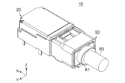
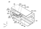
図1及び図2に示されるように、本発明の実施の形態によるコネクタ組立体10は、第1コネクタ20と、第2コネクタ50とを備えている。第1コネクタ20は、レセプタクルであり、回路基板(図示せず)に搭載して使用される。第2コネクタ50は、プラグであり、ケーブル80に接続して使用される。即ち、本実施の形態において、第1コネクタ20は、レセプタクルタイプのオンボードコネクタであり、第2コネクタ50は、プラグタイプのケーブルコネクタである。特に、第1コネクタ20は、所謂アングルタイプのレセプタクルである。但し、本発明は、これに限られず、様々なコネクタ組立体に適用可能である。例えば、第1コネクタ20は、プラグであってもよく、第2コネクタ50は、レセプタクルであってもよい。また、第1コネクタ20は、第2コネクタ50と同様に、ケーブルに接続して使用されるケーブルコネクタであってもよい。
As shown in FIGS. 1 and 2, a
図1及び図2を参照すると、第1コネクタ20と第2コネクタ50とは、前後方向(X方向)に沿って互いに嵌合可能である。図1に示した第1コネクタ20及び第2コネクタ50は、互いに離れた分離状態にあり、第1コネクタ20は、第2コネクタ50の前方に位置している。分離状態にある第2コネクタ50を、第1コネクタ20に向かって前方(+X方向)に移動させると、第1コネクタ20及び第2コネクタ50は、互いに嵌合した嵌合状態(図2の状態)になる。上述のように、第2コネクタ50は、X方向において前方に位置する第1コネクタ20とX方向に沿って嵌合可能である。嵌合状態において、第1コネクタ20と第2コネクタ50とは、互いに電気的に接続され、これにより、第1コネクタ20の回路基板(図示せず)が組み込まれた電子機器(図示せず)とケーブル80に接続された他の電子機器(図示せず)とは、互いに電気的に接続される。
Referring to FIGS. 1 and 2, the
以下、第1コネクタ20の全体的な構造について説明する。
The overall structure of the
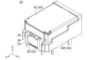
図3から図6までに示されるように、本実施の形態の第1コネクタ20は、第1内側構造体30と、第1外側部材40とを備えている。図16を参照すると、第1内側構造体30は、嵌合状態にある第1コネクタ20と第2コネクタ50とを互いに電気的に接続するための部材である。第1外側部材40は、嵌合状態をロックするための部材である。図3から図6までを参照すると、第1外側部材40は、第1内側構造体30に取り付けられている。より具体的には、第1内側構造体30は、第1外側部材40の内部に前方から挿入されており、これにより、第1コネクタ20が組み立てられている。
As shown in FIGS. 3 to 6, the
本実施の形態の第1コネクタ20は、第1内側構造体30及び第1外側部材40のみを備えている。但し、本発明は、これに限られず、第1コネクタ20は、第1内側構造体30及び第1外側部材40に加えて、更に別の部材を備えていてもよい。
The
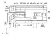
図3から図8までに示されるように、第1内側構造体30は、第1コネクタ本体32を備えている。図7及び図8を参照すると、本実施の形態の第1コネクタ本体32は、導電体からなる第1内側シェル34と、絶縁体からなる第1保持部材36と、導電体からなる複数の第1端子38と、絶縁体からなる整列部材39とを備えている。
As shown in FIGS. 3 to 8, the first
第1保持部材36は、複数の部材を組み合わせて形成されており、平板部362を有している。平板部362は、第1保持部材36の後側部(-X側の部位)であり、水平面(XY平面)に沿って延びている。第1端子38は、第1保持部材36によって保持されている。第1端子38の夫々の一端は、第1コネクタ20の使用時に、回路基板(図示せず)に半田付け等によって固定され接続される。第1端子38の夫々の他端は、平板部362から露出しており、嵌合状態において、第2コネクタ50(図1参照)に電気的に接続される。第1内側シェル34は、X方向と直交する直交平面(YZ平面)において平板部362を囲んでおり、第1コネクタ本体32の後側部のYZ平面における外周を規定している。整列部材39は、第1端子38のうちのいくつかを水平面において整列している。
The first holding
本実施の形態の第1内側構造体30は、上述の構造を有する第1コネクタ本体32のみを備えている。但し、本発明は、これに限られず、第1内側構造体30の構造は、必要に応じて様々に変形可能である。例えば、第1内側構造体30は、第1コネクタ本体32とは別の部材を更に備えていてもよい。また、第1コネクタ本体32は、上述した部材に加えて更に別の部材を備えていてもよい。
The first
図3、図4、図7及び図8を参照すると、本実施の形態の第1外側部材40は、導電体からなる第1外側シェル42と、絶縁体からなる第1外側ハウジング44とを備えている。
Referring to FIGS. 3, 4, 7, and 8, the first
図4及び図6を参照すると、本実施の形態の第1外側ハウジング44は、上板部442と、底板部444と、2つの側板部446と、背板部448とを有している。上板部442は、X方向と直交する上下方向(Z方向)において第1外側ハウジング44の上側(+Z側)に位置しており、XY平面に沿って延びている。底板部444は、第1外側ハウジング44の下側(-Z側)に位置しており、XY平面に沿って延びている。側板部446は、X方向及びZ方向の双方と直交する横方向(Y方向)において第1外側ハウジング44の両側に夫々位置しており、所定平面(XZ平面)に沿って互いに平行に延びている。背板部448は、第1外側ハウジング44の前端(+X側の端)に位置しており、YZ平面に沿って延びている。
Referring to FIGS. 4 and 6, the first
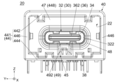
第1外側ハウジング44の上板部442、底板部444及び2つの側板部446は、第1外周部441を形成している。即ち、本実施の形態の第1外側部材40は、第1外周部441を有している。第1コネクタ20には、第1外周部441及び背板部448によって規定される第1受容部22が形成されている。第1受容部22は、YZ平面において第1外周部441によって囲まれた空間であり、後方(-X方向)に開口している。背板部448は、第1受容部22の前端に位置している。
The
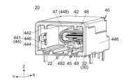
図4、図6、図7及び図8を参照すると、本実施の形態の第1外側ハウジング44は、上述した部位に加えて、保持壁48と、突出部49とを有している。保持壁48及び突出部49は、第1受容部22の内部に位置している。保持壁48は、前方及び後方に開口した筒状の部位である。保持壁48は、背板部448のYZ平面における中間部に設けられており、背板部448から後方に突出している。突出部49は、保持壁48のY方向における中間部に設けられている。突出部49は、保持壁48の下面(-Z側の面)から下方(-Z方向)に張り出しており、且つ、背板部448から、保持壁48の後端(-X側の端)を越えて後方に突出している。本実施の形態の突出部49は、Z方向において底板部444から離れており、突出部49と底板部444との間には、隙間空間45が形成されている。
Referring to FIGS. 4, 6, 7, and 8, the first
図6から図8までを参照すると、第1コネクタ本体32の第1内側シェル34は、YZ平面において保持壁48の内部空間に対応した形状を有している。第1コネクタ本体32は、第1内側シェル34を保持壁48の内部に嵌め込むようにして、前方から第1外側部材40に挿入されて保持されている。保持壁48は、第1内側シェル34を挟み込んで移動しないように保持している。即ち、本実施の形態の第1内側構造体30は、第1外側部材40に対して移動しないようにして保持されている。
Referring to FIGS. 6 to 8, the first
図5及び図8を参照すると、本実施の形態の第1外側ハウジング44は、ロック孔46を有している。本実施の形態のロック孔46は、上板部442に形成された孔である。ロック孔46は、XY平面において矩形形状を有している。ロック孔46は、上板部442のY方向における中間部に位置しており、上板部442をZ方向に貫通している。
Referring to FIGS. 5 and 8, the first
図4を参照すると、本実施の形態の第1外側シェル42は、曲げを有する1枚の金属板である。第1外側シェル42は、第1外側ハウジング44のYZ平面における外周に取り付けられており、主として上板部442及び側板部446を覆っている。
Referring to FIG. 4, the first
本実施の形態の第1外側部材40は、上述の構造を有する第1外側シェル42及び第1外側ハウジング44を備えている。但し、本発明は、これに限られず、第1外側部材40の構造は、様々に変形可能である。例えば、第1外側シェル42は、必要に応じて設ければよい。
The first
以下、第2コネクタ50の全体的な構造について説明する。
The overall structure of the
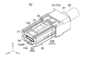
図9から図12までに示されるように、本実施の形態の第2コネクタ50は、第2内側構造体60と、第2外側部材70とを備えている。図16を参照すると、第2内側構造体60は、第1コネクタ20の第1内側構造体30と共に、嵌合状態にある第1コネクタ20と第2コネクタ50とを互いに電気的に接続するための部材である。第2外側部材70は、第1コネクタ20の第1外側部材40と共に、嵌合状態をロックするための部材である。図9から図12までを参照すると、第2外側部材70は、第2内側構造体60に取り付けられている。より具体的には、第2内側構造体60は、第2外側部材70の内部に後方から挿入されており、これにより、第2コネクタ50が組み立てられている。
As shown in FIGS. 9 to 12, the
本実施の形態の第2コネクタ50は、第2内側構造体60及び第2外側部材70のみを備えている。但し、本発明は、これに限られず、第2コネクタ50は、第2内側構造体60及び第2外側部材70に加えて、更に別の部材を備えていてもよい。
The
図9、図13及び図14を参照すると、本実施の形態の第2内側構造体60は、絶縁体からなる保護部材61と、第2コネクタ本体62とを備えている。
Referring to FIGS. 9, 13, and 14, the second
図13及び図14を参照すると、第2コネクタ本体62は、中継基板82を介してケーブル80に接続されている。保護部材61は、第2コネクタ本体62とケーブル80との間の接続部(中継基板82を含む)を覆うようにしてモールド成型されている。このように形成された保護部材61は、ケーブル80に強固に固定されてケーブル80を保護している。第2コネクタ本体62は、保護部材61の前端部に固定されており、保護部材61から前方に突出している。即ち、本実施の形態によれば、第2コネクタ本体62は、部分的に保護部材61の内部に埋め込まれてケーブル80に接続されており、これにより、第2コネクタ50は、ケーブル80に取付けられている。但し、本発明において、第2コネクタ50をケーブル80に取付ける方法は、特に限定されない。
Referring to FIGS. 13 and 14, the second connector
本実施の形態の第2内側構造体60は、全体として上述の構造を有している。但し、本発明は、これに限られない。例えば、第2コネクタ50がレセプタクルである場合、第2内側構造体60は、第2コネクタ本体62のみを備えていてもよい。一方、第2内側構造体60は、保護部材61及び第2コネクタ本体62に加えて、更に別の部材を備えていてもよい。
The second
図12から図14までを参照すると、本実施の形態の第2コネクタ本体62は、導電体からなる第2内側シェル64と、絶縁体からなる第2保持部材66と、導電体からなる複数の第2端子68とを備えている。第2保持部材66は、複数の部材を組み合わせて形成されている。第2端子68は、第2保持部材66によって保持されている。第2内側シェル64は、YZ平面において、第2保持部材66を囲んでいる。第2端子68の夫々の一端は、中継基板82を介してケーブル80の導電線(図示せず)に接続されている。第2端子68の夫々の他端は、第2保持部材66から前方に突出している。図15を参照すると、第2端子68の他端は、嵌合状態において、第2コネクタ50の第1端子38と夫々接触し、これにより、第2内側構造体60に接続されたケーブル80は、第1内側構造体30に接続された回路基板(図示せず)と電気的に接続される。
Referring to FIGS. 12 to 14, the second connector
図13を参照すると、本実施の形態の第2コネクタ本体62は、上述の構造を有する第2内側シェル64、第2保持部材66及び第2端子68のみを備えている。但し、本発明は、これに限られない。例えば、第2コネクタ本体62は、第2内側シェル64、第2保持部材66及び第2端子68に加えて、更に別の部材を備えていてもよい。
Referring to FIG. 13, the second connector
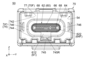
図9を参照すると、本実施の形態の第2外側部材70は、絶縁体からなる第2外側ハウジング74を備えている。図10及び図12を参照すると、本実施の形態の第2外側ハウジング74は、上板部742と、底板部744と、2つの側板部746とを有している。上板部742は、第2外側ハウジング74の上側に位置しており、XY平面に沿って延びている。底板部744は、第2外側ハウジング74の下側に位置しており、XY平面に沿って延びている。側板部746は、Y方向において第2外側ハウジング74の両側に夫々位置しており、XZ平面に沿って互いに平行に延びている。
Referring to FIG. 9, the second
第2外側ハウジング74の上板部742、底板部744及び2つの側板部746は、第2外周部741を形成している。即ち、本実施の形態の第2外側部材70は、第2外周部741を有している。図13及び図14を参照すると、第2内側構造体60は、ケーブル80の端部と共に、後方から第2外周部741の内部に挿入されて保持されており、これにより、第2内側構造体60及び第2外側部材70は、ケーブル80と共にケーブルハーネスを形成している。また、第2コネクタ50には、第2外周部741の前側部(+X側の部位)によって規定される第2受容部54が形成されている。図10を参照すると、第2受容部54は、YZ平面において第2外周部741によって囲まれた空間であり、前方に開口している。保護部材61の前端612は、第2受容部54の後端に位置している。
The
図9から図11までを参照すると、本実施の形態の第2外周部741は、凹部745Rと、被挿入部745とを有している。凹部745Rは、下方に凹んだ凹みであり、底板部744のY方向における中間部に形成されている。凹部745Rは、X方向に沿って延びており、前方に開口している。凹部745Rは、Z方向において第2受容部54と連通している。被挿入部745は、底板部744のうち、凹部745Rの下に位置する部位である。被挿入部745は、XY平面と平行な平板形状を有しており、X方向に沿って延びている。
Referring to FIGS. 9 to 11, the second outer
図9及び図13を参照すると、本実施の形態の第2外側ハウジング74は、上述した部位に加えて、バネ部75を有している。バネ部75は、上板部742を部分的に切り欠いて形成されている。バネ部75のX方向における両端は、上板部742に固定されている。一方、バネ部75のY方向における両側は、上板部742から切り離されている。バネ部75は、上述の構造により、弾性変形可能である。バネ部75には、ロック突起76が形成されている。ロック突起76は、バネ部75のX方向における中間部に位置している。ロック突起76は、バネ部75の弾性変形に伴ってZ方向に移動可能である。
Referring to FIGS. 9 and 13, the second
図13及び図14を参照すると、本実施の形態の第2外側ハウジング74は、ランス78と、受止部79とを有している。ランス78及び受止部79は、第2外周部741の内部に位置している。ランス78は、底板部744から上方及び前方に向かって突出している。ランス78の一部は、保護部材61に設けられた凹み(係合凹部614)に受容されている。ランス78は、係合凹部614と係合しており、これにより、第2内側構造体60が第2外側ハウジング74から抜け出ることを防止している。受止部79は、ランス78が係合凹部614の前側の内壁と接触しているとき、保護部材61の一部(被受止部616)から所定距離DPだけ離れて後方に位置している。第2内側構造体60を前方に移動させると、被受止部616が受止部79と突き当たり、これにより、第2内側構造体60の前方への移動が停止する。
Referring to FIGS. 13 and 14, the second
図14を参照すると、上述の構造から理解されるように、本実施の形態の第2内側構造体60は、第2外側部材70に対してX方向に沿って相対的に所定距離DPだけ移動可能となるように、第2外側部材70に保持されている。本実施の形態によれば、第2外側部材70のランス78は、第2内側構造体60の第2外側部材70に対する最も後方の位置(後方限界位置)を規定しており、第2外側部材70の受止部79は、第2内側構造体60の第2外側部材70に対する最も前方の位置(前方限界位置)を規定している。但し、本発明は、これに限られず、第2内側構造体60の後方限界位置及び前方限界位置を規定する部位又は部材は、特に限定されない。
Referring to FIG. 14, as understood from the above structure, the second
本実施の形態の第2外側部材70は、上述の構造を有する第2外側ハウジング74のみを備えている。但し、本発明は、これに限られず、第2外側部材70の構造は、様々に変形可能である。例えば、第2外側部材70は、第2外側ハウジング74に加えて更に別の部材を備えていてもよい。
The second
以下、第1コネクタ20(図1参照)と第2コネクタ50とが互いに嵌合した嵌合状態について説明する。
The fitted state in which the first connector 20 (see FIG. 1) and the
図1を参照すると、第2コネクタ50は、嵌合部52を有している。嵌合部52は、第2コネクタ50の前側の部位であり、第1コネクタ20の第1受容部22に挿入可能な形状を有している。
Referring to FIG. 1, the
図15及び図16を図7及び図13と併せて参照すると、分離状態(図1の状態)にある第2コネクタ50を、第1コネクタ20に向かって前方に移動すると、第2コネクタ50の嵌合部52は、第1受容部22に受容される。このとき、第1コネクタ20の第1内側構造体30のうち第1受容部22の内部に位置する部位は、第1外側部材40の保持壁48及び突出部49と共に、第2コネクタ50の第2受容部54に受容される。この結果、第1コネクタ本体32の第1端子38は、第2コネクタ本体62の第2端子68と夫々接触する。このとき、第1コネクタ20と第2コネクタ50とは、互いに嵌合した嵌合状態にある。即ち、第2コネクタ本体62は、嵌合状態において、第1コネクタ本体32と接続される。
15 and 16 in conjunction with FIGS. 7 and 13, when the
図15及び図16を参照すると、第2コネクタ50が第1コネクタ20と嵌合する際、第2コネクタ50のロック突起76は、バネ部75を撓ませつつ、第1コネクタ20の上板部442の下面に沿って前方に移動する。第2コネクタ本体62が第1コネクタ本体32と接続されたとき、ロック突起76は、第1コネクタ20のロック孔46に到達し、バネ部75は、初期状態に復元する。この結果、ロック突起76は、ロック孔46に受容される。このとき、第2コネクタ50を後方に引くと、ロック突起76の後面(-X側の面)がロック孔46の後側の内壁に押し付けられ、第2コネクタ50は、第1コネクタ20から抜去できない。即ち、ロック突起76は、ロック孔46と共に、嵌合状態をロックしている。一方、バネ部75を撓ませてロック突起76をロック孔46の下方に移動することで、嵌合状態のロックを解除でき、これにより、第2コネクタ50を抜去できる。
15 and 16, when the
上述のように、第1コネクタ20及び第2コネクタ50の嵌合状態は、第1コネクタ20の第1外側部材40と第2コネクタ50の第2外側部材70とによってロックされる。従来のコネクタ組立体によれば、嵌合状態がロックされる前に、第2コネクタ本体62が第1コネクタ本体32と突き当たる可能性がある。この場合、嵌合状態がロックされたとき、第2コネクタ本体62が第1コネクタ本体32に押し付けられて破損するおそれがある。一方、本実施の形態のコネクタ組立体10は、第1コネクタ本体32及び第2コネクタ本体62の破損を防止する破損防止構造を有している。以下、コネクタ組立体10の破損防止構造について説明する。
As described above, the fitted state of the
図8を参照すると、第1コネクタ20の第1外側部材40は、第1ロック面462と、第1規制部47と、第1突当部492とを有している。第1ロック面462は、前方に向いている。第1規制部47は、後方に向いている。第1突当部492は、後方に向いている。
Referring to FIG. 8, the first
本実施の形態において、第1ロック面462は、ロック孔46の後側の内壁面である。第1規制部47は、背板部448の後面である。第1突当部492は、突出部49の後面である。また、第1規制部47及び第1突当部492の夫々は、第1受容部22の内部に位置している。但し、本発明は、これに限られない。例えば、第1ロック面462、第1規制部47及び第1突当部492は、上述の方向を向いている限り、第1外側部材40のどの部位であってもよい。また、第1ロック面462、第1規制部47及び第1突当部492の配置は、本実施の形態に限定されない。
In this embodiment, the
図14を参照すると、第2コネクタ50の第2内側構造体60は、第2突当部(前端)612を有しており、第2コネクタ50の第2外側部材70は、第2ロック面762と、第2規制部77とを有している。第2ロック面762は、後方に向いている。第2規制部77は、前方に向いている。第2突当部612は、前方に向いている。
Referring to FIG. 14, the second
本実施の形態において、第2ロック面762は、ロック突起76の後面である。第2規制部77は、第2外側部材70の前端70Fである。第2突当部612は、保護部材61の前端であり、第2受容部54の内部に位置している。但し、本発明は、これに限られない。例えば、第2ロック面762及び第2規制部77は、上述の方向を向いている限り、第2外側部材70のどの部位であってもよい。第2突当部612は、上述の方向を向いている限り、第2内側構造体60のどの部位であってもよい。また、第2ロック面762、第2規制部77及び第2突当部612の配置は、本実施の形態に限定されない。
In this embodiment, the
図16を参照すると、嵌合操作の操作者は、第2突当部612が第1突当部492に突き当たって、第2コネクタ50の第1コネクタ20に対する前方移動が停止したときに、第2コネクタ50が第1コネクタ20と完全に嵌合したことを認識する。換言すれば、第2突当部612は、第2コネクタ50が第1コネクタ20と嵌合するとき、第1突当部492に突き当たり、これにより、第2コネクタ50の前方への更なる移動が防止される。この構造によれば、第1突当部492及び第2突当部612のX方向における位置を、第1コネクタ20及び第2コネクタ50の様々な部材の公差を考慮しつつ設計することにより、第2コネクタ50の第2コネクタ本体62が第1コネクタ20の第1コネクタ本体32に突き当たるまで移動することを防止できる。
Referring to FIG. 16, when the
より具体的には、図7及び図8を参照すると、本実施の形態の第1コネクタ本体32は、対向部322を有している。図13及び図14を参照すると、本実施の形態の第2コネクタ本体62は、先端部622を有している。図16を参照すると、第1突当部492と第2突当部612とが互いに突き当たった完全な嵌合状態において、対向部322と先端部622とは、X方向において互いに離れており且つ対向している。即ち、対向部322と先端部622とが互いに突き当たって押し付けられることによる第1コネクタ本体32及び第2コネクタ本体62の破損が防止されている。加えて、第1内側構造体30が前方に向かう力を受けることに起因する第1内側構造体30の位置ずれや第1外側部材40からの脱落が防止されている。
More specifically, referring to FIGS. 7 and 8, the
本実施の形態によれば、第2コネクタ50が第1コネクタ20と嵌合する際、第2コネクタ本体62は、第1コネクタ本体32に受容される。また、対向部322は、第1保持部材36の一部であり、先端部622は、第2内側シェル64の前端64Fである。但し、本発明は、これに限られない。例えば、対向部322及び先端部622は、どの部材に設けられていてもよい。また、第2コネクタ50が第1コネクタ20と嵌合する際、第1コネクタ本体32が、第2コネクタ本体62に受容されてもよい。この場合、第1コネクタ本体32が先端部を有していてもよく、第2コネクタ本体62が対向部を有していてもよい。
According to this embodiment, when the
嵌合状態において、第2ロック面762は、第1ロック面462とX方向において対向(接触を含む)しており、第2コネクタ50の第1コネクタ20に対する後方への相対移動を規制している。加えて、嵌合状態において、第2規制部77は、第1規制部47とX方向において対向(接触を含む)しており、第2コネクタ50の第1コネクタ20に対する前方への相対移動を規制している。換言すれば、嵌合状態において、第2コネクタ50の第1コネクタ20に対するX方向における移動は、X方向において対向する第2ロック面762及び第1ロック面462と、X方向において対向する第2規制部77及び第1規制部47とによって規制される。即ち、第1コネクタ20の第1外側部材40と第2コネクタ50の第2外側部材70とによって嵌合状態がロックされる。
In the fitted state, the
本実施の形態によれば、第2ロック面762のX方向における位置は、第1コネクタ20及び第2コネクタ50の様々な部材の公差を考慮しつつ、第2ロック面762が嵌合状態において第1ロック面462から離れて位置できるように設計されている。加えて、第2規制部77のX方向における位置は、上述した公差を考慮しつつ、第2規制部77が嵌合状態において第1規制部47から離れて位置できるように設計されている。
According to the present embodiment, the position of the
より具体的には、第1コネクタ20の第1規制部47と第1ロック面462とは、X方向において第1距離D1だけ互いに離れている。第2コネクタ50の第2規制部77と第2ロック面762とは、X方向において第2距離D2だけ互いに離れている。本実施の形態によれば、第1規制部47は、第1ロック面462の前方に位置しており、且つ、第1距離D1は、第2距離D2よりも長い。この結果、嵌合状態において、第2外側部材70は、第1外側部材40に対してX方向に沿って相対的に移動可能である。即ち、本実施の形態によれば、公差を許容しつつ、第1コネクタ20を第2コネクタ50と嵌合する際の第1コネクタ本体32及び第2コネクタ本体62の破損を防止可能なコネクタ組立体10を提供できる。
More specifically, the first restricting
本実施の形態において、第1規制部47、第1ロック面462、第2規制部77及び第2ロック面762の夫々は、YZ平面と平行な平面である。但し、本発明は、これに限られない。例えば、第1規制部47、第1ロック面462、第2規制部77及び第2ロック面762の夫々は、X方向と斜交する斜面であってもよい。上述した第1距離D1及び第2距離D2の夫々は、このような場合も考慮に入れた距離であり、第1規制部47、第1ロック面462、第2規制部77及び第2ロック面762の全てを通過するX方向と平行な仮想的な直線(仮想直線)に沿った距離である。また、本実施の形態によれば、上述の条件を満たす仮想直線のいずれについても、上述した定義による第1距離D1(以下、単に「第1距離D1」という。)は、上述した定義による第2距離D2(以下、単に「第2距離D2」という。)よりも長い。
In this embodiment, each of the first restricting
前述したように、本実施の形態の第2内側構造体60は、第2外側部材70に対してX方向に沿って所定距離DP(図14参照)だけ相対的に移動可能である。本実施の形態によれば、この構造により、第2外側部材70は、第1突当部492と第2突当部612とが互いに突き当たった完全な嵌合状態において、第1外側部材40に対してX方向に沿って所定距離DPだけ相対的に移動可能である。換言すれば、本実施の形態によれば、第2内側構造体60に対する第2外側部材70の移動を許容することで、第2外側部材70の第1外側部材40に対する相対的な移動を可能にし、これにより、第1コネクタ本体32及び第2コネクタ本体62の破損を防止している。但し、本発明は、これに限られない。例えば、第1コネクタ20の第1内側構造体30は、第2コネクタ50と同様に、第1外側部材40に対して相対的に移動可能であってもよい。
As described above, the second
前述したように、本実施の形態の第1規制部47は、第1ロック面462の前方に位置している。但し、本発明は、これに限られず、第1規制部47は、第1ロック面462の後方に位置していてもよい。この場合、第1距離D1が第2距離D2よりも短くなるように設計することで、本実施の形態と同様に、第1コネクタ20を第2コネクタ50と嵌合する際の第1コネクタ本体32及び第2コネクタ本体62の破損を防止可能なコネクタ組立体10を提供できる。即ち、第1規制部47が第1ロック面462の前方に位置している場合、第1距離D1は、第2距離D2よりも長ければよく、第1規制部47が第1ロック面462の後方に位置している場合、第1距離D1は、第2距離D2よりも短ければよい。
As described above, the first restricting
上述したコネクタ組立体10の破損防止構造を別の観点から説明すると、本実施の形態の第2規制部77及び第2ロック面762は、嵌合状態において、第2外側部材70の第1外側部材40に対する移動(ガタツキ)を許容するようにして、第1規制部47及び第1ロック面462の間に位置している。但し、本発明は、これに限られない。第2規制部77及び第2ロック面762は、嵌合状態において、第2外側部材70の第1外側部材40に対する移動(ガタツキ)を許容するようにして、第1規制部47及び第1ロック面462を間に挟んでいてもよい。
To explain the damage prevention structure of the
本実施の形態のコネクタ組立体10は、既に説明した変形例に加えて、更に様々に変形可能である。以下、これらの変形例について説明する。
The
本実施の形態によれば、レセプタクルである第1コネクタ20の第1外側部材40に第1突当部492及びロック孔46が設けられている。また、プラグである第2コネクタ50の第2内側構造体60に第2突当部612が設けられており、第2外側部材70にロック突起76が設けられている。但し、本発明は、これに限られない。例えば、プラグである第1コネクタの第1外側部材に第1突当部及びロック突起を設けてもよい。この場合、レセプタクルである第2コネクタの第2内側構造体に第2突当部を設け、且つ、第2外側部材にロック孔を設けてもよい。
According to this embodiment, the first abutting
本実施の形態によれば、ロック孔46は、第1外側部材40に対して移動しないように設けられており、ロック突起76は、第2外側部材70に対して移動可能に設けられている。但し、本発明は、これに限られない。例えば、ロック突起を、第1外側部材40に対して移動しないように、第1外側部材40に設けてもよい。この場合、ロック孔を、第2外側部材70に対して移動可能になるように、第2外側部材70に設けてもよい。
According to this embodiment, the
本実施の形態によれば、第1突当部492は、第1コネクタ本体32の後方に位置している。この構造によれば、第2コネクタ50を第1コネクタ20と嵌合する際、第2コネクタ本体62が第1コネクタ本体32に近づく前に、第2突当部612を第1突当部492に確実に突き当てることができる。即ち、第1コネクタ本体32及び第2コネクタ本体62の破損を防止し易い。但し、本発明は、これに限られず、第1突当部492の位置は、必要に応じて設計すればよい。
According to this embodiment, the first abutting
図7を参照すると、本実施の形態の第1外側部材40において、第1外周部441の底板部444と、突出部49とは、Z方向において隙間空間45を挟んで対向している。換言すれば、第1外周部441は、YZ平面において、部分的に隙間空間45を挟んで第1突当部492の外側に位置している。図13を参照すると、本実施の形態の第2外側部材70の第2外周部741は、YZ平面において、第2コネクタ本体62を覆っている。図15及び図16を参照すると、第2コネクタ50を第1コネクタ20と嵌合する際、第1外側部材40の突出部49は、第2外側部材70の凹部745R(図10参照)に挿入され、底板部744の被挿入部745は、隙間空間45に挿入される。この結果、嵌合状態において、第2外周部741の被挿入部745は、第1外周部441のYZ平面における内側に位置しており、且つ、隙間空間45の内部に位置している。
Referring to FIG. 7, in the first
図9を参照すると、上述した構造によれば、第2受容部54を、第2外周部741によって切れ目なく完全に覆うことができ、これにより、第2受容部54への異物の侵入を防止できる。但し、本発明は、本実施の形態に限られない。図15及び図16を参照すると、例えば、第1外周部441は、YZ平面において、少なくとも部分的に隙間空間45を挟んで第1突当部492の外側に位置していてもよい。また、嵌合状態において、第2外周部741は、少なくとも部分的に第1外周部441のYZ平面における内側に位置しており、且つ、少なくとも部分的に隙間空間45の内部に位置していてもよい。
Referring to FIG. 9, according to the above-described structure, the second receiving
図14を参照すると、本実施の形態によれば、第2外側部材70の前端70Fは、第2コネクタ本体62の前端64Fの前方に位置している。換言すれば、第2コネクタ本体62の前端64Fは、第2受容部54の内部に位置している。この構造によれば、第2コネクタ本体62の破損を防止し易い。但し、本発明は、これに限られず、第2外側部材70に対する第2コネクタ本体62の位置は、必要に応じて設計すればよい。
Referring to FIG. 14, according to the present embodiment, the
本実施の形態によれば、第2突当部612は、第2コネクタ本体62の前端64Fの後方に位置している。この構造によれば、第2コネクタ本体62を、第1受容部22(図8参照)の内部に深く挿入でき、これにより、第1コネクタ本体32と第2コネクタ本体62とを、より安定的に接続できる。但し、本発明は、これに限られず、第2コネクタ本体62に対する第2突当部612の位置は、必要に応じて設計すればよい。
According to this embodiment, the second abutting
10 コネクタ組立体
20 第1コネクタ
22 第1受容部
30 第1内側構造体
32 第1コネクタ本体
322 対向部
34 第1内側シェル
36 第1保持部材
362 平板部
38 第1端子
39 整列部材
40 第1外側部材
42 第1外側シェル
44 第1外側ハウジング
441 第1外周部
442 上板部
444 底板部
446 側板部
448 背板部
45 隙間空間
46 ロック孔
462 第1ロック面
47 第1規制部
48 保持壁
49 突出部
492 第1突当部
50 第2コネクタ
52 嵌合部
54 第2受容部
60 第2内側構造体
61 保護部材
612 前端(第2突当部)
614 係合凹部
616 被受止部
62 第2コネクタ本体
622 先端部
64 第2内側シェル
64F 前端
66 第2保持部材
68 第2端子
70 第2外側部材
70F 前端
74 第2外側ハウジング
741 第2外周部
742 上板部
744 底板部
745 被挿入部
745R 凹部
746 側板部
75 バネ部
76 ロック突起
762 第2ロック面
77 第2規制部
78 ランス
79 受止部
80 ケーブル
82 中継基板
10
614 Engagement recessed
Claims (8)
前記第2コネクタは、前後方向において前方に位置する第1コネクタと前記前後方向に沿って嵌合可能であり、
前記第1コネクタは、第1内側構造体と、第1外側部材とを備えており、
前記第1内側構造体は、第1コネクタ本体を備えており、
前記第1外側部材は、前記第1内側構造体に取り付けられており、
前記第1外側部材は、第1ロック面と、第1規制部と、第1突当部とを有しており、
前記第1ロック面は、前方に向いており、
前記第1規制部は、後方に向いており、
前記第1突当部は、後方に向いており、
前記第2コネクタは、第2内側構造体と、第2外側部材とを備えており、
前記第2内側構造体は、第2コネクタ本体と、第2突当部とを備えており、
前記第2コネクタ本体は、前記第1コネクタと前記第2コネクタとが互いに嵌合した嵌合状態において、前記第1コネクタ本体と接続され、
前記第2突当部は、前方に向いており、
前記第2突当部は、前記第2コネクタが前記第1コネクタと嵌合するとき、前記第1突当部に突き当たり、
前記第2外側部材は、前記第2内側構造体に取り付けられており、
前記第2外側部材は、第2ロック面と、第2規制部とを有しており、
前記第2ロック面は、後方に向いており、
前記嵌合状態において、前記第2ロック面は、前記第1ロック面と前記前後方向において対向しており、前記第2コネクタの前記第1コネクタに対する後方への相対移動を規制しており、
前記第2規制部は、前方に向いており、
前記嵌合状態において、前記第2規制部は、前記第1規制部と前記前後方向において対向しており、前記第2コネクタの前記第1コネクタに対する前方への相対移動を規制しており、
前記第1規制部と前記第1ロック面とは、前記前後方向において第1距離だけ互いに離れており、
前記第2規制部と前記第2ロック面とは、前記前後方向において第2距離だけ互いに離れており、
前記第1規制部が前記第1ロック面の前方に位置している場合、前記第1距離は、前記第2距離よりも長く、
前記第1規制部が前記第1ロック面の後方に位置している場合、前記第1距離は、前記第2距離よりも短く、
前記嵌合状態において、前記第2外側部材は、前記第1外側部材に対して前記前後方向に沿って相対的に移動可能である
コネクタ組立体。 A connector assembly comprising a first connector and a second connector,
The second connector can be fitted along the front-back direction with the first connector located at the front in the front-back direction,
The first connector includes a first inner structure and a first outer member,
The first inner structure includes a first connector body,
the first outer member is attached to the first inner structure,
The first outer member has a first locking surface, a first regulating part, and a first abutting part,
the first locking surface faces forward;
The first regulating portion faces rearward;
The first abutting portion faces rearward,
The second connector includes a second inner structure and a second outer member,
The second inner structure includes a second connector main body and a second abutting portion,
The second connector body is connected to the first connector body in a fitted state in which the first connector and the second connector are fitted to each other,
the second abutting portion faces forward;
the second abutting portion abuts against the first abutting portion when the second connector is fitted with the first connector;
the second outer member is attached to the second inner structure,
The second outer member has a second locking surface and a second regulating portion,
the second locking surface faces rearward;
In the fitted state, the second locking surface faces the first locking surface in the front-rear direction, and restricts rearward relative movement of the second connector with respect to the first connector;
the second regulating portion faces forward;
In the fitted state, the second restriction part faces the first restriction part in the front-rear direction, and restricts forward relative movement of the second connector with respect to the first connector;
The first restricting portion and the first locking surface are separated from each other by a first distance in the front-rear direction,
The second restricting portion and the second locking surface are separated from each other by a second distance in the front-rear direction,
when the first restriction part is located in front of the first locking surface, the first distance is longer than the second distance;
When the first restriction part is located behind the first locking surface, the first distance is shorter than the second distance,
In the fitted state, the second outer member is movable relative to the first outer member along the front-rear direction.
前記第2内側構造体は、前記第2外側部材に対して前記前後方向に沿って所定距離だけ相対的に移動可能となるように、前記第2外側部材に保持されている
コネクタ組立体。 The connector assembly according to claim 1, comprising:
A connector assembly in which the second inner structure is held by the second outer member so as to be movable relative to the second outer member by a predetermined distance along the front-rear direction.
前記第1コネクタ本体は、対向部を有しており、
前記第2コネクタ本体は、先端部を有しており、
前記嵌合状態において、前記対向部と前記先端部とは、前記前後方向において互いに離れており且つ対向している
コネクタ組立体。 The connector assembly according to claim 1 or claim 2,
The first connector body has a facing portion,
The second connector body has a tip,
In the fitted state, the facing portion and the tip end portion are separated from each other in the front-rear direction and face each other.
前記第2コネクタが前記第1コネクタと嵌合する際、前記第2コネクタ本体は、前記第1コネクタ本体に受容される
コネクタ組立体。 4. The connector assembly according to claim 3,
The second connector body is received by the first connector body when the second connector is mated with the first connector.
前記第2外側部材の前端は、前記第2コネクタ本体の前端の前方に位置している
コネクタ組立体。 A connector assembly according to any one of claims 1 to 4,
A front end of the second outer member is located in front of a front end of the second connector body.
前記第1外側部材は、第1外周部を有しており、
前記第1外周部は、前記前後方向と直交する直交平面において、少なくとも部分的に隙間空間を挟んで前記第1突当部の外側に位置しており、
前記第2外側部材は、第2外周部を有しており、
前記第2外周部は、前記直交平面において、前記第2コネクタ本体を覆っており、
前記嵌合状態において、前記第2外周部は、少なくとも部分的に前記第1外周部の前記直交平面における内側に位置しており、且つ、少なくとも部分的に前記隙間空間の内部に位置している
コネクタ組立体。 A connector assembly according to any one of claims 1 to 5,
The first outer member has a first outer peripheral portion,
The first outer circumferential portion is located at least partially outside the first abutting portion with a gap space in between in an orthogonal plane perpendicular to the front-rear direction,
The second outer member has a second outer peripheral portion,
The second outer peripheral portion covers the second connector main body in the orthogonal plane,
In the fitted state, the second outer circumference is at least partially located inside the first outer circumference in the orthogonal plane, and at least partially inside the gap space. connector assembly.
前記第1突当部は、前記第1コネクタ本体の後方に位置している
コネクタ組立体。 A connector assembly according to any one of claims 1 to 6,
In the connector assembly, the first abutting portion is located at the rear of the first connector body.
前記第2突当部は、前記第2コネクタ本体の前端の後方に位置している
コネクタ組立体。 A connector assembly according to any one of claims 1 to 7,
In the connector assembly, the second abutting portion is located behind a front end of the second connector body.
Priority Applications (4)
| Application Number | Priority Date | Filing Date | Title |
|---|---|---|---|
| JP2020009806A JP7348090B2 (en) | 2020-01-24 | 2020-01-24 | connector assembly |
| US17/089,868 US11309661B2 (en) | 2020-01-24 | 2020-11-05 | Connector assembly |
| CN202011289208.1A CN113258355B (en) | 2020-01-24 | 2020-11-17 | Connector assembly |
| EP20209081.7A EP3855578B1 (en) | 2020-01-24 | 2020-11-20 | Connector assembly |
Applications Claiming Priority (1)
| Application Number | Priority Date | Filing Date | Title |
|---|---|---|---|
| JP2020009806A JP7348090B2 (en) | 2020-01-24 | 2020-01-24 | connector assembly |
Publications (3)
| Publication Number | Publication Date |
|---|---|
| JP2021118077A JP2021118077A (en) | 2021-08-10 |
| JP2021118077A5 JP2021118077A5 (en) | 2022-12-20 |
| JP7348090B2 true JP7348090B2 (en) | 2023-09-20 |
Family
ID=73543213
Family Applications (1)
| Application Number | Title | Priority Date | Filing Date |
|---|---|---|---|
| JP2020009806A Active JP7348090B2 (en) | 2020-01-24 | 2020-01-24 | connector assembly |
Country Status (4)
| Country | Link |
|---|---|
| US (1) | US11309661B2 (en) |
| EP (1) | EP3855578B1 (en) |
| JP (1) | JP7348090B2 (en) |
| CN (1) | CN113258355B (en) |
Families Citing this family (8)
| Publication number | Priority date | Publication date | Assignee | Title |
|---|---|---|---|---|
| USD916661S1 (en) * | 2018-02-28 | 2021-04-20 | Molex, Llc | Connector housing |
| USD984382S1 (en) * | 2019-05-09 | 2023-04-25 | Ideal Industries, Inc. | Electrical connector |
| JP1670022S (en) * | 2020-05-29 | 2020-10-12 | ||
| JP1676724S (en) * | 2020-06-15 | 2021-01-18 | ||
| JP1678796S (en) * | 2020-06-15 | 2021-02-08 | ||
| JP1695884S (en) * | 2021-03-02 | 2021-09-27 | ||
| JP1695883S (en) * | 2021-03-02 | 2021-09-27 | ||
| JP1703880S (en) * | 2021-04-02 | 2022-01-04 |
Citations (5)
| Publication number | Priority date | Publication date | Assignee | Title |
|---|---|---|---|---|
| JP2003331989A (en) | 2002-05-08 | 2003-11-21 | Sumitomo Wiring Syst Ltd | Dividing connector |
| JP2012160445A (en) | 2011-02-01 | 2012-08-23 | Delphi Technologies Inc | Electrical connection system including connector body with integral primary and secondary latch |
| JP2015153615A (en) | 2014-02-14 | 2015-08-24 | 株式会社オートネットワーク技術研究所 | connector |
| JP6310216B2 (en) | 2013-09-06 | 2018-04-11 | キヤノン株式会社 | Radiation detection apparatus, manufacturing method thereof, and radiation detection system |
| US20190190200A1 (en) | 2017-12-20 | 2019-06-20 | Lotes Co., Ltd | Electrical connector assembly |
Family Cites Families (15)
| Publication number | Priority date | Publication date | Assignee | Title |
|---|---|---|---|---|
| JP3534013B2 (en) * | 1999-10-06 | 2004-06-07 | 住友電装株式会社 | connector |
| US7063577B2 (en) | 2002-05-08 | 2006-06-20 | Sumitomo Wiring Systems, Ltd. | Split-type connector assembly and method of assembling it |
| JP4278673B2 (en) * | 2006-10-17 | 2009-06-17 | ヒロセ電機株式会社 | Electrical connector |
| US7666023B2 (en) * | 2008-05-22 | 2010-02-23 | Hon Hai Precision Ind. Co., Ltd. | Electrical connector with a latch coupled to a pull member |
| CN202601982U (en) * | 2012-06-08 | 2012-12-12 | 泰科电子(上海)有限公司 | Connector assembly and connector product |
| US9461374B2 (en) * | 2013-03-15 | 2016-10-04 | Molex, Llc | Electrical connector assembly and connecting member thereof |
| JP6230471B2 (en) | 2014-04-09 | 2017-11-15 | ホシデン株式会社 | connector |
| JP2016110851A (en) * | 2014-12-08 | 2016-06-20 | 矢崎総業株式会社 | connector |
| JP6647825B2 (en) | 2015-09-29 | 2020-02-14 | 日本航空電子工業株式会社 | Connectors and connector assemblies |
| JP6525854B2 (en) | 2015-11-24 | 2019-06-05 | 日本航空電子工業株式会社 | Connector and connector assembly |
| EP3373398B1 (en) * | 2017-03-10 | 2023-03-29 | TE Connectivity Germany GmbH | Connector assembly with improved lever gear transmission |
| JP6806606B2 (en) | 2017-03-23 | 2021-01-06 | 日本航空電子工業株式会社 | connector |
| JP6667965B2 (en) * | 2017-08-31 | 2020-03-18 | 矢崎総業株式会社 | connector |
| CN207542475U (en) | 2017-11-29 | 2018-06-26 | 番禺得意精密电子工业有限公司 | Electric connector |
| CN208045870U (en) | 2018-04-03 | 2018-11-02 | 富誉电子科技(淮安)有限公司 | Female end socket, public terminal plug and electric connector combination |
-
2020
- 2020-01-24 JP JP2020009806A patent/JP7348090B2/en active Active
- 2020-11-05 US US17/089,868 patent/US11309661B2/en active Active
- 2020-11-17 CN CN202011289208.1A patent/CN113258355B/en active Active
- 2020-11-20 EP EP20209081.7A patent/EP3855578B1/en active Active
Patent Citations (5)
| Publication number | Priority date | Publication date | Assignee | Title |
|---|---|---|---|---|
| JP2003331989A (en) | 2002-05-08 | 2003-11-21 | Sumitomo Wiring Syst Ltd | Dividing connector |
| JP2012160445A (en) | 2011-02-01 | 2012-08-23 | Delphi Technologies Inc | Electrical connection system including connector body with integral primary and secondary latch |
| JP6310216B2 (en) | 2013-09-06 | 2018-04-11 | キヤノン株式会社 | Radiation detection apparatus, manufacturing method thereof, and radiation detection system |
| JP2015153615A (en) | 2014-02-14 | 2015-08-24 | 株式会社オートネットワーク技術研究所 | connector |
| US20190190200A1 (en) | 2017-12-20 | 2019-06-20 | Lotes Co., Ltd | Electrical connector assembly |
Also Published As
| Publication number | Publication date |
|---|---|
| JP2021118077A (en) | 2021-08-10 |
| EP3855578B1 (en) | 2023-03-01 |
| EP3855578A1 (en) | 2021-07-28 |
| CN113258355A (en) | 2021-08-13 |
| CN113258355B (en) | 2023-06-27 |
| US20210234305A1 (en) | 2021-07-29 |
| US11309661B2 (en) | 2022-04-19 |
Similar Documents
| Publication | Publication Date | Title |
|---|---|---|
| JP7348090B2 (en) | connector assembly | |
| JP2018142456A (en) | connector | |
| US9246260B2 (en) | Electrical connector | |
| JP7144305B2 (en) | connector assembly | |
| JP6097072B2 (en) | connector | |
| JP6372428B2 (en) | Joint connector | |
| CN111146606A (en) | Electric connector and electric connector set | |
| JP2007220557A (en) | Electric connector assembly | |
| CN110323613B (en) | Connector and terminal component | |
| JP6144122B2 (en) | Electrical connector | |
| CN112864706B (en) | Connector assembly | |
| WO2020100731A1 (en) | Connector | |
| JP5668986B2 (en) | Shield connector | |
| CN112186418B (en) | Connector assembly | |
| WO2021112258A1 (en) | Connector | |
| JP6782735B2 (en) | Terminal fittings and the engagement structure between the terminal fittings and the housing | |
| JP7009976B2 (en) | Connector and connector device | |
| JPS61161679A (en) | Electric connector for receptacle | |
| JP6996487B2 (en) | connector | |
| JP7453865B2 (en) | connector assembly | |
| JP7435373B2 (en) | connector | |
| TWI715199B (en) | Connector and terminal | |
| JP7159807B2 (en) | connector | |
| JP2007115632A (en) | Electrical connector with locking mechanism | |
| JP2022047668A (en) | Shield connector |
Legal Events
| Date | Code | Title | Description |
|---|---|---|---|
| A521 | Request for written amendment filed |
Free format text: JAPANESE INTERMEDIATE CODE: A523 Effective date: 20221209 |
|
| A621 | Written request for application examination |
Free format text: JAPANESE INTERMEDIATE CODE: A621 Effective date: 20221209 |
|
| A977 | Report on retrieval |
Free format text: JAPANESE INTERMEDIATE CODE: A971007 Effective date: 20230814 |
|
| TRDD | Decision of grant or rejection written | ||
| A01 | Written decision to grant a patent or to grant a registration (utility model) |
Free format text: JAPANESE INTERMEDIATE CODE: A01 Effective date: 20230823 |
|
| A61 | First payment of annual fees (during grant procedure) |
Free format text: JAPANESE INTERMEDIATE CODE: A61 Effective date: 20230907 |
|
| R150 | Certificate of patent or registration of utility model |
Ref document number: 7348090 Country of ref document: JP Free format text: JAPANESE INTERMEDIATE CODE: R150 |