JP6996487B2 - connector - Google Patents

connector Download PDF

Info

Publication number
JP6996487B2
JP6996487B2 JP2018240689A JP2018240689A JP6996487B2 JP 6996487 B2 JP6996487 B2 JP 6996487B2 JP 2018240689 A JP2018240689 A JP 2018240689A JP 2018240689 A JP2018240689 A JP 2018240689A JP 6996487 B2 JP6996487 B2 JP 6996487B2
Authority
JP
Japan
Prior art keywords
housing
fitting
protective
female
retainer
Prior art date
Legal status (The legal status is an assumption and is not a legal conclusion. Google has not performed a legal analysis and makes no representation as to the accuracy of the status listed.)
Active
Application number
JP2018240689A
Other languages
Japanese (ja)
Other versions
JP2020102390A (en
Inventor
哲矢 宮村
Current Assignee (The listed assignees may be inaccurate. Google has not performed a legal analysis and makes no representation or warranty as to the accuracy of the list.)
Sumitomo Wiring Systems Ltd
AutoNetworks Technologies Ltd
Sumitomo Electric Industries Ltd
Original Assignee
Sumitomo Wiring Systems Ltd
AutoNetworks Technologies Ltd
Sumitomo Electric Industries Ltd
Priority date (The priority date is an assumption and is not a legal conclusion. Google has not performed a legal analysis and makes no representation as to the accuracy of the date listed.)
Filing date
Publication date
Application filed by Sumitomo Wiring Systems Ltd, AutoNetworks Technologies Ltd, Sumitomo Electric Industries Ltd filed Critical Sumitomo Wiring Systems Ltd
Priority to JP2018240689A priority Critical patent/JP6996487B2/en
Priority to CN201980085419.2A priority patent/CN113228426B/en
Priority to US17/413,430 priority patent/US20220059962A1/en
Priority to PCT/JP2019/047871 priority patent/WO2020137453A1/en
Publication of JP2020102390A publication Critical patent/JP2020102390A/en
Application granted granted Critical
Publication of JP6996487B2 publication Critical patent/JP6996487B2/en
Active legal-status Critical Current
Anticipated expiration legal-status Critical

Links

Images

Classifications

    • HELECTRICITY
    • H01ELECTRIC ELEMENTS
    • H01RELECTRICALLY-CONDUCTIVE CONNECTIONS; STRUCTURAL ASSOCIATIONS OF A PLURALITY OF MUTUALLY-INSULATED ELECTRICAL CONNECTING ELEMENTS; COUPLING DEVICES; CURRENT COLLECTORS
    • H01R13/00Details of coupling devices of the kinds covered by groups H01R12/70 or H01R24/00 - H01R33/00
    • H01R13/40Securing contact members in or to a base or case; Insulating of contact members
    • H01R13/42Securing in a demountable manner
    • H01R13/436Securing a plurality of contact members by one locking piece or operation
    • H01R13/4367Insertion of locking piece from the rear
    • HELECTRICITY
    • H01ELECTRIC ELEMENTS
    • H01RELECTRICALLY-CONDUCTIVE CONNECTIONS; STRUCTURAL ASSOCIATIONS OF A PLURALITY OF MUTUALLY-INSULATED ELECTRICAL CONNECTING ELEMENTS; COUPLING DEVICES; CURRENT COLLECTORS
    • H01R13/00Details of coupling devices of the kinds covered by groups H01R12/70 or H01R24/00 - H01R33/00
    • H01R13/62Means for facilitating engagement or disengagement of coupling parts or for holding them in engagement
    • H01R13/627Snap or like fastening
    • H01R13/6271Latching means integral with the housing
    • H01R13/6272Latching means integral with the housing comprising a single latching arm
    • HELECTRICITY
    • H01ELECTRIC ELEMENTS
    • H01RELECTRICALLY-CONDUCTIVE CONNECTIONS; STRUCTURAL ASSOCIATIONS OF A PLURALITY OF MUTUALLY-INSULATED ELECTRICAL CONNECTING ELEMENTS; COUPLING DEVICES; CURRENT COLLECTORS
    • H01R12/00Structural associations of a plurality of mutually-insulated electrical connecting elements, specially adapted for printed circuits, e.g. printed circuit boards [PCB], flat or ribbon cables, or like generally planar structures, e.g. terminal strips, terminal blocks; Coupling devices specially adapted for printed circuits, flat or ribbon cables, or like generally planar structures; Terminals specially adapted for contact with, or insertion into, printed circuits, flat or ribbon cables, or like generally planar structures
    • H01R12/70Coupling devices
    • H01R12/71Coupling devices for rigid printing circuits or like structures
    • H01R12/712Coupling devices for rigid printing circuits or like structures co-operating with the surface of the printed circuit or with a coupling device exclusively provided on the surface of the printed circuit
    • H01R12/716Coupling device provided on the PCB

Description

本発明は、コネクタに関するものである。 The present invention relates to a connector.

特許文献1には、ハウジングと端子金具とリテーナとを備えたコネクタが開示されている。端子金具は、ハウジングの後方からハウジング内に挿入される。リテーナは、端子金具を挿入した後にハウジングの後端部に組み付けられる。リテーナを組み付けた状態では、リテーナの抜止め部が端子金具に対して後方から当たることにより、端子金具が抜止め状態に保持される。 Patent Document 1 discloses a connector including a housing, a terminal fitting, and a retainer. The terminal fitting is inserted into the housing from the rear of the housing. The retainer is attached to the rear end of the housing after inserting the terminal fittings. In the state where the retainer is assembled, the retaining portion of the retainer hits the terminal fitting from behind, so that the terminal fitting is held in the retaining state.

特開平11-67318号公報Japanese Unexamined Patent Publication No. 11-67318

近年、コネクタの小型化が進んでいるが、端子金具とリテーナの抜止め部が小型化されると、端子金具に対する抜止め部の位置が僅かにずれただけで、リテーナによる抜止め機能が低下する虞がある。かかる問題は、端子金具を抜止めするためのリテーナに限らず、ハウジングに各種機能部材を取り付けるものにおいても、同様に生じる課題である。 In recent years, the size of the connector has been miniaturized, but when the terminal fitting and the retainer retaining part are miniaturized, the position of the retaining portion with respect to the terminal fitting is slightly displaced, and the retaining function by the retainer is deteriorated. There is a risk of This problem is not limited to the retainer for disconnecting and retaining the terminal fittings, but is also a problem that arises in those that attach various functional members to the housing.

本発明は上記のような事情に基づいて完成されたものであって、ハウジングに対して機能部材を適正な形態で取り付けることができるようにすることを目的とする。 The present invention has been completed based on the above circumstances, and an object of the present invention is to enable the functional member to be attached to the housing in an appropriate form.

本発明は、
端子金具が取り付けられるハウジングと、
前記ハウジングに形成され、後端部がロック解除用の操作部となっているロックアームと、
前記ハウジングに形成され、前記操作部を覆う保護部と、
前記ハウジングの後端部に取り付けられる機能部材と、
前記保護部に形成された受け部と、
前記機能部材に形成され、前記機能部材が前記ハウジングに対して適正な形態で取り付けられたときに前記受け部に嵌合可能な嵌込部とを備えていることを特徴とする。
The present invention
The housing to which the terminal fittings are attached and
A lock arm formed in the housing and whose rear end is an operation unit for unlocking,
A protective portion formed in the housing and covering the operation portion, and a protective portion.
A functional member attached to the rear end of the housing and
The receiving portion formed in the protective portion and
It is characterized in that it is formed on the functional member and includes an fitting portion that can be fitted to the receiving portion when the functional member is attached to the housing in an appropriate form.

この構成によれば、機能部材がハウジングに対して適正に取り付けられると、嵌込部と受け部が嵌合することにより、機能部材がハウジングに対して位置決めされる。これにより、機能部材をハウジングに対して適正な取付け状態に保持することができる。 According to this configuration, when the functional member is properly attached to the housing, the fitting portion and the receiving portion are fitted to position the functional member with respect to the housing. As a result, the functional member can be held in an appropriate mounting state with respect to the housing.

実施例1の雌側コネクタを雄側コネクタに嵌合した状態をあらわす背面図Rear view showing a state in which the female connector of the first embodiment is fitted to the male connector. 雌側コネクタを雄側コネクタに嵌合した状態をあらわす平面図A plan view showing the state in which the female connector is fitted to the male connector. 図1のA-A線断面図FIG. 1 is a cross-sectional view taken along the line AA. 雌側ハウジングの正面図Front view of female housing 雌側ハウジングの平面図Top view of the female side housing リテーナの正面図Front view of retainer リテーナの平面図Floor plan of retainer 図6のB-B線断面図BB line sectional view of FIG. 実施例2の雌側コネクタを雄側コネクタに嵌合した状態をあらわす平面図A plan view showing a state in which the female connector of the second embodiment is fitted to the male connector. 図9のC-C線相当断面図FIG. 9 is a cross-sectional view corresponding to the line CC. 雌側ハウジングの背面図Rear view of female housing 雌側ハウジングの平面図Top view of the female side housing リテーナの平面図Floor plan of retainer 実施例3の雌側コネクタを雄側コネクタに嵌合した状態をあらわす背面図Rear view showing a state in which the female connector of Example 3 is fitted to the male connector. 雌側コネクタを雄側コネクタに嵌合した状態をあらわす平面図A plan view showing the state in which the female connector is fitted to the male connector. 図14のD-D線相当断面図FIG. 14 is a cross-sectional view corresponding to the DD line. 雌側ハウジングの平面図Top view of the female side housing 雌側ハウジングの側面図Side view of female housing リテーナの平面図Floor plan of retainer 図19のE-E線断面図FIG. 19 is a sectional view taken along line EE.

本発明は、前記機能部材に形成され、前記操作部のうち前記保護部で覆われない領域を覆う覆い部を備えていてもよい。この構成によれば、操作部は、保護部だけでなく覆い部によっても覆われるので、操作部を異物の干渉から保護することができる。 The present invention may include a covering portion formed on the functional member and covering a region of the operating portion that is not covered by the protective portion. According to this configuration, the operating portion is covered not only by the protective portion but also by the covering portion, so that the operating portion can be protected from the interference of foreign matter.

本発明は、前記嵌込部が前記覆い部に一体に形成されていてもよい。この構成によれば、受け部と嵌込部との嵌合により、保護部に対する覆い部の位置ずれを防止することができる。 In the present invention, the fitting portion may be integrally formed with the covering portion. According to this configuration, it is possible to prevent the position of the covering portion from being displaced with respect to the protective portion by fitting the receiving portion and the fitting portion.

本発明は、前記保護部が、前記ハウジングの外面から枠状に延出して前記操作部を囲む形態であり、前記受け部が、前記保護部のうち前記操作部との対向面を凹ませた形態であり、前記嵌込部が、前記機能部材から突出して前記保護部の内側に潜り込んだ状態で前記受け部に嵌合するようになっていてもよい。この構成によれば、受け部と嵌込部の嵌合部分が保護部の内側に位置しているので、受け部と嵌込部との嵌合部分に異物が干渉する虞がない。 In the present invention, the protective portion extends from the outer surface of the housing in a frame shape to surround the operation portion, and the receiving portion recesses the surface of the protection portion facing the operation portion. It is a form, and the fitting portion may be fitted to the receiving portion in a state where the fitting portion protrudes from the functional member and slips into the inside of the protection portion. According to this configuration, since the fitting portion between the receiving portion and the fitting portion is located inside the protective portion, there is no possibility that foreign matter interferes with the fitting portion between the receiving portion and the fitting portion.

本発明は、一対の前記保護部が、前記ハウジングの外面から片持ち状に延出して前記操作部を側方から挟むように配され、前記一対の保護部の延出端部が、前記受け部として機能するようになっており、前記嵌込部が、前記一対の受け部の間に嵌入されるようになっていてもよい。この構成によれば、受け部と嵌込部の嵌合状態を目視によって確認することができる。 In the present invention, the pair of protective portions are arranged so as to extend cantilevered from the outer surface of the housing and sandwich the operation portion from the side, and the extended end portion of the pair of protective portions is the receiving portion. It is designed to function as a portion, and the fitting portion may be fitted between the pair of receiving portions. According to this configuration, the fitted state of the receiving portion and the fitting portion can be visually confirmed.

本発明は、前記機能部材が前後方向に貫通した形態の開口部を有し、前記開口部の開口縁部が前記嵌込部となっており、前記保護部が、前記ハウジングの外面から枠状に延出して前記操作部を囲む形態であり、前記受け部が、前記保護部から片持ち状に突出して前記開口部内に収容された状態で前記嵌込部と嵌合するようになっていてもよい。この構成によれば、受け部と嵌込部の嵌合部分が開口部の内側に位置しているので、受け部と嵌込部との嵌合部分に異物が干渉する虞がない。 In the present invention, the functional member has an opening in the form of penetrating in the front-rear direction, the opening edge portion of the opening serves as the fitting portion, and the protective portion has a frame shape from the outer surface of the housing. The receiving portion is cantilevered from the protective portion and is accommodated in the opening so as to be fitted to the fitting portion. May be good. According to this configuration, since the fitting portion between the receiving portion and the fitting portion is located inside the opening portion, there is no possibility that foreign matter interferes with the fitting portion between the receiving portion and the fitting portion.

本発明は、前記端子金具が前記ハウジングに対して後方から挿入されるようになっており、前記機能部材が、前記ハウジングの後端部に取り付けられることで、前記端子金具を抜止め状態に保持するリテーナであってもよい。 In the present invention, the terminal fitting is inserted from the rear with respect to the housing, and the functional member is attached to the rear end portion of the housing to hold the terminal fitting in a retaining state. It may be a retainer.

<実施例1>
以下、本発明を具体化した実施例1を図1~図8を参照して説明する。尚、以下の説明において、前後の方向については、図2,3,5,7,8における左方を前方と定義する。上下の方向については、図1,3,4,6,8にあらわれる向きを、そのまま上方、下方と定義する。
<Example 1>
Hereinafter, Example 1 embodying the present invention will be described with reference to FIGS. 1 to 8. In the following description, regarding the front-back direction, the left side in FIGS. 2, 3, 5, 7, and 8 is defined as the front. As for the vertical direction, the directions appearing in FIGS. 1, 3, 4, 6 and 8 are defined as upward and downward as they are.

本実施例1の雌側コネクタFa(請求項に記載のコネクタ)は、合成樹脂製の雌側ハウジング10(請求項に記載のハウジング)と、一対の雌端子金具24(請求項に記載の端子金具)と、合成樹脂製のリテーナ30(請求項に記載の機能部材)とを備えて構成されている。 The female side connector Fa (the connector according to the claim) of the first embodiment is a synthetic resin female side housing 10 (the housing according to the claim) and a pair of female terminal fittings 24 (the terminal according to the claim). A metal fitting) and a retainer 30 made of synthetic resin (functional member according to claim) are provided.

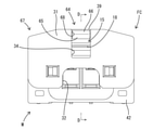
図3~5に示すように、雌側ハウジング10は、端子収容部11と、ロックアーム15と、保護部20とを一体に形成した単一部材である。端子収容部11は全体としてブロック状をなし、端子収容部11内には左右一対の端子収容室12が左右に並んで形成されている。端子収容室12の下面には、上下方向へ弾性変形可能なランス(図示省略)が形成されている。端子収容室12の後端は、端子収容部11(雌側ハウジング10)の後端面において端子挿入口として開口されている。図4に示すように、端子収容部11の左右両外側面には、端子収容部11の後端面に開放された左右一対のガイド凹部13が形成されている。一対のガイド凹部13には、左右一対の係止突起14が形成されている。 As shown in FIGS. 3 to 5, the female side housing 10 is a single member in which the terminal accommodating portion 11, the lock arm 15, and the protective portion 20 are integrally formed. The terminal accommodating portion 11 has a block shape as a whole, and a pair of left and right terminal accommodating chambers 12 are formed side by side in the terminal accommodating portion 11. A lance (not shown) that can be elastically deformed in the vertical direction is formed on the lower surface of the terminal accommodating chamber 12. The rear end of the terminal accommodating chamber 12 is opened as a terminal insertion port on the rear end surface of the terminal accommodating portion 11 (female side housing 10). As shown in FIG. 4, a pair of left and right guide recesses 13 opened to the rear end surface of the terminal accommodating portion 11 are formed on both the left and right outer surfaces of the terminal accommodating portion 11. A pair of left and right locking projections 14 are formed in the pair of guide recesses 13.

図3に示すように、ロックアーム15は、端子収容部11の上面(外面)に沿うように配されている。ロックアーム15は、端子収容部11の上面に沿って前後方向に細長く延びたアーム本体部16と、アーム本体部16の前端部から下方へ延出して端子収容部11の上面に連なる支持部17と、アーム本体部16の後端部に形成したロック解除用の操作部18とを備えて構成されている。 As shown in FIG. 3, the lock arm 15 is arranged along the upper surface (outer surface) of the terminal accommodating portion 11. The lock arm 15 has an arm main body 16 elongated in the front-rear direction along the upper surface of the terminal accommodating portion 11 and a support portion 17 extending downward from the front end portion of the arm main body 16 and connecting to the upper surface of the terminal accommodating portion 11. And an operation unit 18 for unlocking formed at the rear end portion of the arm main body portion 16.

ロックアーム15は支持部17を支点として上下方向へ弾性変形し得るようになっている。アーム本体部16の上面のうち操作部18よりも前方の位置には、ロック突起19が形成されている。操作部18は、アーム本体部16の後端を後方へ延長した形態である。操作部18に対し下向きの外力が作用すると、ロックアーム15がロック解除方向へ変位するようになっている。 The lock arm 15 can be elastically deformed in the vertical direction with the support portion 17 as a fulcrum. A lock protrusion 19 is formed on the upper surface of the arm main body 16 at a position in front of the operation portion 18. The operation unit 18 has a form in which the rear end of the arm main body 16 is extended rearward. When a downward external force acts on the operation unit 18, the lock arm 15 is displaced in the unlocking direction.

保護部20は、操作部18を異物の干渉から保護するための部位である。図3,4に示すように、保護部20は、左右一対の側面側保護部21と上面側保護部22とにより枠状に構成されている。左右一対の側面側保護部21は、端子収容部11の上面における後端部から上方(ロックアーム15側)へ立ち上がり、操作部18の左右両側面を覆うように配されている。上面側保護部22は、左右一対の側面側保護部21の上端部同士を連結した形態であり、操作部18の上面を覆うように配されている。保護部20は、操作部18に対する上方からの異物の干渉と、操作部18に対する左右両側方からの異物の干渉のみを防止する。保護部20及び雌側ハウジング10には、操作部18を後方から覆う部位は形成されていない。 The protection unit 20 is a portion for protecting the operation unit 18 from the interference of foreign matter. As shown in FIGS. 3 and 4, the protective portion 20 is formed in a frame shape by a pair of left and right side surface side protective portions 21 and an upper surface side protective portion 22. The pair of left and right side protection portions 21 rise upward (on the lock arm 15 side) from the rear end portion on the upper surface of the terminal accommodating portion 11 and are arranged so as to cover the left and right side surfaces of the operation portion 18. The upper surface side protection portion 22 has a form in which the upper end portions of the pair of left and right side surface side protection portions 21 are connected to each other, and is arranged so as to cover the upper surface of the operation portion 18. The protection unit 20 prevents only the interference of foreign matter from above with respect to the operation unit 18 and the interference of foreign matter with foreign matter from both the left and right sides with respect to the operation unit 18. The protective portion 20 and the female side housing 10 are not formed with a portion that covers the operation portion 18 from the rear.

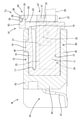
図3,4に示すように、保護部20には、受け部23が一体に形成されている。受け部23は、上面側保護部22の左右方向における中央部、即ち左右方向において操作部18と対応する領域に配されている。受け部23は、上面側保護部22のうち操作部18の上面と対向する領域の一部を凹ませた形態である。詳細には、受け部23は、上面側保護部22の下面における前縁部と、上面側保護部22の前面における下端縁部とを溝状に凹ませた形態である。換言すると、受け部23は、上面側保護部22の下方及び上面側保護部22の前方に開放された形態である。受け部23は、操作部18の上面に対して上下方向に対向する位置関係となっている。 As shown in FIGS. 3 and 4, a receiving portion 23 is integrally formed in the protective portion 20. The receiving portion 23 is arranged in the central portion of the upper surface side protective portion 22 in the left-right direction, that is, in the region corresponding to the operation portion 18 in the left-right direction. The receiving portion 23 is in a form in which a part of the region of the upper surface side protective portion 22 facing the upper surface of the operation portion 18 is recessed. Specifically, the receiving portion 23 has a form in which the leading edge portion on the lower surface of the upper surface side protective portion 22 and the lower end edge portion on the front surface of the upper surface side protective portion 22 are recessed in a groove shape. In other words, the receiving portion 23 is in a form of being opened below the upper surface side protection portion 22 and in front of the upper surface side protection portion 22. The receiving portion 23 has a positional relationship facing the upper surface of the operating portion 18 in the vertical direction.

図3に示すように、雌端子金具24は、前端部に角筒部25を有し、後端部にはオープンバレル状の圧着部26を有している。角筒部25内には弾性接触片(図示省略)が収容されている。角筒部25の下面には突起状の一次係止部(図示省略)が形成されている。角筒部25の後部は、二次係止部27として機能する。圧着部26には、被覆電線28が導通可能に圧着されている。 As shown in FIG. 3, the female terminal fitting 24 has a square tube portion 25 at the front end portion and an open barrel-shaped crimping portion 26 at the rear end portion. An elastic contact piece (not shown) is housed in the square tube portion 25. A protrusion-shaped primary locking portion (not shown) is formed on the lower surface of the square cylinder portion 25. The rear portion of the square tube portion 25 functions as a secondary locking portion 27. A covered electric wire 28 is electrically crimped to the crimping portion 26.

雌端子金具24は、雌側ハウジング10の後方から端子収容室12内に挿入される。正規挿入された雌端子金具24は、図示は省略するが、一次係止部をランスに引っ掛ける一次係止構造により抜止め状態に保持される。雌端子金具24に固着された被覆電線28は、雌側ハウジング10の後方へ導出されている。 The female terminal fitting 24 is inserted into the terminal accommodating chamber 12 from the rear of the female side housing 10. Although not shown, the normally inserted female terminal fitting 24 is held in a retaining state by a primary locking structure in which the primary locking portion is hooked on a lance. The coated electric wire 28 fixed to the female terminal fitting 24 is led out to the rear of the female side housing 10.

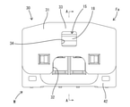
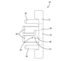
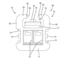
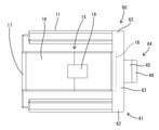
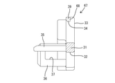
図6~8に示すように、リテーナ30は、壁部31と、左右一対の抜止め突起35と、左右一対の弾性係止片36とを有する単一部品である。壁部31は、壁厚方向を前後方向(雌側ハウジング10に対する雌端子金具24の着脱方向と平行な方向)に向けた略平板状をなす。雌側ハウジング10にリテーナ30を取り付けた状態で、雌側ハウジング10に対する雌端子金具24の取付け方向と同じ方向に見ることを、背面視と定義する。 As shown in FIGS. 6 to 8, the retainer 30 is a single component having a wall portion 31, a pair of left and right retaining protrusions 35, and a pair of left and right elastic locking pieces 36. The wall portion 31 has a substantially flat plate shape with the wall thickness direction directed in the front-rear direction (direction parallel to the attachment / detachment direction of the female terminal fitting 24 with respect to the female side housing 10). With the retainer 30 attached to the female housing 10, viewing in the same direction as the attachment direction of the female terminal fitting 24 to the female housing 10 is defined as rear view.

背面視において、壁部31は、雌側ハウジング10の後面のうち少なくとも保護部20の全体と操作部18の一部を覆う形状及び大きさを有している。壁部31には、背面視において複数の端子収容室12と対応する領域を切り欠いた形態の逃がし凹部32が形成されている。逃がし凹部32は、壁部31の下端縁に開口されている。 In rear view, the wall portion 31 has a shape and size that covers at least the entire protection portion 20 and a part of the operation portion 18 in the rear surface of the female side housing 10. The wall portion 31 is formed with a relief recess 32 in a form in which a region corresponding to the plurality of terminal accommodating chambers 12 is cut out in the rear view. The relief recess 32 is opened at the lower end edge of the wall portion 31.

壁部31の一部は、覆い部33としての機能を有している。即ち、壁部31のうち左右方向における中央部であり、上下方向においては中央高さより上方の部位が、覆い部33を構成している。換言すると、壁部31のうち背面視において保護部20の全体と対応する領域と、壁部31のうち背面視において操作部18の左右両端部と対応する領域が、覆い部33となっている。 A part of the wall portion 31 has a function as a covering portion 33. That is, the central portion of the wall portion 31 in the left-right direction, and the portion above the central height in the vertical direction constitutes the covering portion 33. In other words, the area of the wall portion 31 corresponding to the entire protection unit 20 in the rear view and the area of the wall portion 31 corresponding to the left and right ends of the operation unit 18 in the rear view are the covering portions 33. ..

図1,3,6,8に示すように、壁部31には、前後方向(壁部31の厚さ方向)に貫通した形態の操作孔34(開口部)が形成されている。操作孔34は、背面視において操作部18の左右方向中央部のみと対応する領域に亘って方形に開口している。操作孔34の開口領域における上端縁は、ロックアーム15が弾性撓みしていない自由状態であるときに、操作部18の上面よりも上方の位置であり、且つ上面側保護部22の下面よりも下方の位置に設定されている。操作孔34の開口領域における下端縁は、端子収容部11の上面とほぼ同じ高さに位置する。 As shown in FIGS. 1, 3, 6 and 8, the wall portion 31 is formed with an operation hole 34 (opening) penetrating in the front-rear direction (thickness direction of the wall portion 31). The operation hole 34 is rectangularly opened over a region corresponding only to the central portion in the left-right direction of the operation portion 18 in the rear view. The upper end edge of the opening region of the operation hole 34 is located above the upper surface of the operation portion 18 and above the lower surface of the upper surface side protection portion 22 when the lock arm 15 is in a free state without elastic bending. It is set in the lower position. The lower end edge of the opening region of the operation hole 34 is located at substantially the same height as the upper surface of the terminal accommodating portion 11.

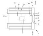
左右一対の抜止め突起35は、壁部31の前面(雌側ハウジング10の後面と対向する面)から前方へ片持ち状に突出した形態である。一対の抜止め突起35は、上下方向及び左右方向(背面視)において、雌端子金具24の二次係止部27と対応する位置に配されている。左右一対の弾性係止片36は、壁部31の左右両側縁から前方へ片持ち状に延出した形態である。弾性係止片36には、左右方向に貫通した形態の係止孔37が形成されている。弾性係止片36は、左右方向へ弾性変形し得るようになっている。 The pair of left and right retaining protrusions 35 are cantilevered forward from the front surface of the wall portion 31 (the surface facing the rear surface of the female housing 10). The pair of retaining protrusions 35 are arranged at positions corresponding to the secondary locking portion 27 of the female terminal fitting 24 in the vertical direction and the horizontal direction (rear view). The pair of left and right elastic locking pieces 36 are in a cantilevered manner extending forward from both left and right edges of the wall portion 31. The elastic locking piece 36 is formed with a locking hole 37 penetrating in the left-right direction. The elastic locking piece 36 can be elastically deformed in the left-right direction.

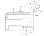
図3,6~8に示すように、リテーナ30には嵌込部38が一体に形成されている。嵌込部38は、壁部31の前面から前方へ片持ち状に延出した形態である。嵌込部38の左右方向における形成範囲は、受け部23と対応する領域であり、リテーナ30(壁部31)の左右方向中央部である。嵌込部38の上下方向における形成範囲は、受け部23と概ね対応する領域である。 As shown in FIGS. 3, 6 to 8, the retainer 30 is integrally formed with the fitting portion 38. The fitting portion 38 has a cantilevered shape extending forward from the front surface of the wall portion 31. The formation range of the fitting portion 38 in the left-right direction is a region corresponding to the receiving portion 23, and is a central portion in the left-right direction of the retainer 30 (wall portion 31). The formation range of the fitting portion 38 in the vertical direction is a region substantially corresponding to the receiving portion 23.

嵌込部38は、壁部31の前面のうち操作孔34の開口縁の上縁部39から前方へ片持ち状に突出した平板状の基部40と、基部40の突出端縁から上方へ突出した突起部41とから構成されている。ロックアーム15の弾性変位方向、及び雌側ハウジング10に対するリテーナ30の取付け方向の両方向に対して直交する方向から見た形状を、側面視形状と定義する。嵌込部38の側面視形状は、略L字形に屈曲した形状である。リテーナ30を雌側ハウジング10に適正に取り付けた状態では、嵌込部38の突起部41が雌側ハウジング10の受け部23に嵌合される。 The fitting portion 38 has a flat plate-shaped base portion 40 that cantilevers forward from the upper edge portion 39 of the opening edge of the operation hole 34 on the front surface of the wall portion 31, and a flat plate-shaped base portion 40 that protrudes upward from the protruding end edge of the base portion 40. It is composed of a protruding portion 41. The shape seen from the direction orthogonal to both the elastic displacement direction of the lock arm 15 and the mounting direction of the retainer 30 with respect to the female side housing 10 is defined as a side view shape. The side view shape of the fitting portion 38 is a shape bent into a substantially L shape. When the retainer 30 is properly attached to the female housing 10, the protrusion 41 of the fitting portion 38 is fitted to the receiving portion 23 of the female housing 10.

リテーナ30は、雌側ハウジング10に雌端子金具24を挿入した後、雌側ハウジング10(端子収容部11)の後端部に組み付けられる。組み付ける際には、被覆電線28のうち雌側ハウジング10の後方へ導出されている領域に対し上から逃がし凹部32を嵌め込み、弾性係止片36をガイド凹部13に嵌合させながら、リテーナ30の壁部31を後方から雌側ハウジング10に接近させる。壁部31が端子収容部11の後端に接近するのに伴い、抜止め突起35が端子収容室12内に挿入される。 The retainer 30 is assembled to the rear end portion of the female side housing 10 (terminal accommodating portion 11) after inserting the female terminal fitting 24 into the female side housing 10. When assembling, the recess 32 is fitted into the region of the covered electric wire 28 that is led out to the rear of the female housing 10, and the elastic locking piece 36 is fitted into the guide recess 13 while the retainer 30 is assembled. The wall portion 31 is brought closer to the female side housing 10 from the rear. As the wall portion 31 approaches the rear end of the terminal accommodating portion 11, the retaining protrusion 35 is inserted into the terminal accommodating chamber 12.

リテーナ30が正規の組付け状態に至ると、左右両弾性係止片36の係止孔37が一対の係止突起14に係止することにより、リテーナ30が雌側ハウジング10に対して組付け状態にロックされる。また、抜止め突起35が雌端子金具24の二次係止部27に対して後方から当接する状態、又は後方から接近して対向する状態となるので、雌端子金具24は、ランスによる一次係止作用とリテーナ30による二次係止作用とによって確実に抜止め状態に保持される。 When the retainer 30 reaches the normal assembly state, the retainer 30 is assembled to the female side housing 10 by engaging the locking holes 37 of the left and right elastic locking pieces 36 with the pair of locking projections 14. Locked to state. Further, since the retaining protrusion 35 is in contact with the secondary locking portion 27 of the female terminal fitting 24 from the rear, or is in a state of approaching and facing the secondary locking portion 27 from the rear, the female terminal fitting 24 is initially engaged by the lance. It is surely held in the retaining state by the stopping action and the secondary locking action by the retainer 30.

図3に示すように、リテーナ30が雌側ハウジング10に対して適正に取り付けられると、嵌込部38の突起部41が雌側ハウジング10の受け部23に嵌合される。受け部23に対する嵌込部38の嵌合により、雌側ハウジング10に対するリテーナ30の後方への相対変位と、雌側ハウジング10に対するリテーナ30の左右方向への相対変位とが規制される。これにより、リテーナ30の壁部31が端子収容部11に対して適正な位置関係に保持されるので、壁部31に形成されている抜止め突起35と端子収容部11に収容されている雌端子金具24の二次係止部27も、適正な位置関係に保たれる。したがって、リテーナ30によって雌端子金具24を抜止めする機能の信頼性に優れている。 As shown in FIG. 3, when the retainer 30 is properly attached to the female side housing 10, the protrusion 41 of the fitting portion 38 is fitted to the receiving portion 23 of the female side housing 10. The fitting of the fitting portion 38 to the receiving portion 23 regulates the rearward displacement of the retainer 30 with respect to the female housing 10 and the lateral displacement of the retainer 30 with respect to the female housing 10. As a result, the wall portion 31 of the retainer 30 is held in an appropriate positional relationship with respect to the terminal accommodating portion 11, so that the retaining protrusion 35 formed on the wall portion 31 and the female housed in the terminal accommodating portion 11 are accommodated. The secondary locking portion 27 of the terminal fitting 24 is also maintained in an appropriate positional relationship. Therefore, the reliability of the function of retaining the female terminal fitting 24 by the retainer 30 is excellent.

雌側ハウジング10に対するリテーナ30の取付け方向、及び左右一対の弾性係止片36の対向方向の両方向に対して直交する方向から見た状態を、平面視と定義する。平面視において、リテーナ30が雌側ハウジング10に対して斜め姿勢(即ち、不正な形態)で取り付けられた場合には、左右一対の弾性係止片36のうち一方の弾性係止片36の係止孔37が雌側ハウジング10の係止突起14に係止し、他方の弾性係止片36の係止孔37は係止突起14に係止しない状態となる。この場合、嵌込部38の突起部41が受け部23よりも後方の位置に留まり、嵌込部38が受け部23内に嵌合できない。そのため、リテーナ30が雌側ハウジング10に対して相対変位し得る状態となり、雌側ハウジング10に対するリテーナ30の位置が安定しない。 The state viewed from the direction orthogonal to both the mounting direction of the retainer 30 with respect to the female side housing 10 and the opposite directions of the pair of left and right elastic locking pieces 36 is defined as a plan view. In a plan view, when the retainer 30 is attached to the female side housing 10 in an oblique posture (that is, in an improper form), the elastic locking piece 36 of one of the pair of left and right elastic locking pieces 36 is engaged. The stop hole 37 is locked to the locking projection 14 of the female side housing 10, and the locking hole 37 of the other elastic locking piece 36 is not locked to the locking projection 14. In this case, the protrusion 41 of the fitting portion 38 stays at a position behind the receiving portion 23, and the fitting portion 38 cannot be fitted in the receiving portion 23. Therefore, the retainer 30 can be displaced relative to the female housing 10, and the position of the retainer 30 with respect to the female housing 10 is not stable.

また、リテーナ30を適正に雌側ハウジング10に組み付けた状態では、覆い部33がロックアーム15の操作部18を後方から覆う状態となる。したがって、後方から異物が操作部18に接近しても、その異物が操作部18に接触する虞はない。また、覆い部33は、保護部20と前後に接近して並ぶように配置されている。したがって、覆い部33の前面と保護部20の後面との隙間から異物が侵入する虞はない。 Further, when the retainer 30 is properly assembled to the female side housing 10, the covering portion 33 is in a state of covering the operating portion 18 of the lock arm 15 from the rear. Therefore, even if a foreign object approaches the operation unit 18 from behind, there is no possibility that the foreign substance will come into contact with the operation unit 18. Further, the covering portion 33 is arranged so as to be close to the protective portion 20 in the front-rear direction. Therefore, there is no possibility that foreign matter will enter through the gap between the front surface of the covering portion 33 and the rear surface of the protecting portion 20.

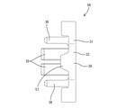
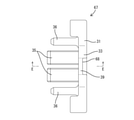
図3に示すように、雌側コネクタFaは雄側コネクタMと嵌合可能である。雄側コネクタMは、回路基板(図示省略)に取り付けられる基板用コネクタとしての機能を有する。雄側コネクタMは、雄側ハウジング42と、雄側ハウジング42に取り付けた一対の雄端子金具43とを備えて構成されている。雄側ハウジング42は、壁状の端子貫通部44と、端子貫通部44の外周縁から正面側(雌側コネクタFa側)へ角筒状に突出したフード部45とを有する。フード部45を構成する上面部にはロック孔46が形成されている。雄端子金具43は端子貫通部44に貫通され、雄端子金具43の先端のタブ(図示省略)はフード部45内に収容され、雄端子金具43の基板接続部47は回路基板(図示省略)に半田付けにより固着されている。 As shown in FIG. 3, the female side connector Fa can be fitted with the male side connector M. The male side connector M has a function as a board connector attached to a circuit board (not shown). The male connector M includes a male housing 42 and a pair of male terminal fittings 43 attached to the male housing 42. The male side housing 42 has a wall-shaped terminal penetrating portion 44 and a hood portion 45 protruding from the outer peripheral edge of the terminal penetrating portion 44 toward the front side (female side connector Fa side) in a square cylinder shape. A lock hole 46 is formed in the upper surface portion constituting the hood portion 45. The male terminal fitting 43 is penetrated through the terminal penetrating portion 44, the tab at the tip of the male terminal fitting 43 (not shown) is housed in the hood portion 45, and the board connection portion 47 of the male terminal fitting 43 is a circuit board (not shown). It is fixed to by soldering.

雌側コネクタFaを雄側コネクタMに嵌合する過程では、ロック突起19がフード部45の上面部と干渉することにより、ロックアーム15が下方へ弾性撓みする。そして、両コネクタFa,Mが正規の嵌合状態に至ると、ロックアーム15が弾性復帰してロック突起19をロック孔46に係止させる。このロック突起19とロック孔46との係止により、両コネクタFa,Mが嵌合状態にロックされる。 In the process of fitting the female connector Fa to the male connector M, the lock projection 19 interferes with the upper surface portion of the hood portion 45, so that the lock arm 15 elastically bends downward. Then, when both the connectors Fa and M reach the normal mating state, the lock arm 15 elastically returns and locks the lock protrusion 19 to the lock hole 46. By locking the lock protrusion 19 and the lock hole 46, both connectors Fa and M are locked in the fitted state.

もし、作業者が指で操作部18を摘んだ状態で両コネクタFa,Mの嵌合作業を行い、作業後に操作部18から指を離した場合、ロックアーム15が勢い良く弾性復帰することがないので、アーム本体部16はフード部45の上面部に衝突しない。したがって、衝撃音が発生せず、衝突に起因する衝撃(クリック感)が雌側コネクタFaを摘んでいる作業者に伝わることもない。そのため、作業者は、両コネクタFa,Mが正規嵌合されたか否かを判断することができない。 If the operator performs the fitting work of both connectors Fa and M with the operation unit 18 picked up by a finger and then releases the finger from the operation unit 18 after the work, the lock arm 15 may vigorously return to elasticity. Since there is no arm body portion 16, the arm body portion 16 does not collide with the upper surface portion of the hood portion 45. Therefore, no impact sound is generated, and the impact (click feeling) caused by the collision is not transmitted to the operator who is picking the female side connector Fa. Therefore, the operator cannot determine whether or not both connectors Fa and M are normally fitted.

この対策として、本実施例1では、リテーナ30に操作部18を後方から覆う覆い部33を形成した。これにより、雌側コネクタFaを雄側コネクタMのフード部45に押し込む際に、リテーナ30の壁部31を後方から指で押しても、その指が操作部18に接触する虞はない。したがって、両コネクタFa,Mが正規嵌合に至ったときには、ロックアーム15が、必ず、ロックアーム15の弾性復元力により上方へ弾性復帰し、アーム本体部16の上面がフード部45の上面部に確実に衝突する。この衝突により、衝突音が発生するとともに、衝突に起因する衝撃(クリック感)が雌側コネクタFaを摘んでいる作業者に伝わる。この衝突音とクリック感により、作業者は両コネクタFa,Mが正規嵌合されたと判断できる。 As a countermeasure, in the first embodiment, the retainer 30 is formed with a covering portion 33 that covers the operating portion 18 from behind. As a result, when the female connector Fa is pushed into the hood portion 45 of the male connector M, even if the wall portion 31 of the retainer 30 is pushed with a finger from behind, there is no possibility that the finger will come into contact with the operation portion 18. Therefore, when both connectors Fa and M reach normal fitting, the lock arm 15 always elastically returns upward due to the elastic restoring force of the lock arm 15, and the upper surface of the arm body 16 is the upper surface of the hood 45. Will definitely collide with. Due to this collision, a collision sound is generated, and the impact (click feeling) caused by the collision is transmitted to the operator who is picking the female side connector Fa. From this collision sound and click feeling, the operator can determine that both connectors Fa and M are normally fitted.

嵌合状態の両コネクタFa,Mを離脱する際には、リテーナ30の後方から治具(図示省略)を操作孔34に挿通し、治具の先端を操作部18の上面に当てる。そして、治具の先端部を下方へ変位させると、ロックアーム15がロック解除方向へ弾性撓みさせられるので、ロック突起19がロック孔46から解離され、両コネクタFa,Mのロック状態が解除される。この後は、ロック解除状態を保持したまま、雌側コネクタFaをフード部45から引き抜けばよい。 When disconnecting both the connectors Fa and M in the fitted state, a jig (not shown) is inserted into the operation hole 34 from the rear of the retainer 30, and the tip of the jig is brought into contact with the upper surface of the operation portion 18. Then, when the tip of the jig is displaced downward, the lock arm 15 is elastically flexed in the unlocking direction, so that the lock protrusion 19 is dissociated from the lock hole 46, and the locked states of both connectors Fa and M are released. To. After that, the female side connector Fa may be pulled out from the hood portion 45 while maintaining the unlocked state.

本実施例1の雌側コネクタFaは、雌端子金具24が取り付けられる雌側ハウジング10と、雌側ハウジング10(端子収容部11)の後端部に取り付けられるリテーナ30とを備えて構成されている。雌側ハウジング10には、後端部がロック解除用の操作部18となっているロックアーム15が形成されている。雌側ハウジング10には、操作部18を覆う保護部20が形成されている。保護部20には受け部23が形成されている。リテーナ30には、リテーナ30が雌側ハウジング10に対して適正な形態で取り付けられたときにのみ、受け部23に嵌合される嵌込部38が形成されている。 The female connector Fa of the first embodiment includes a female housing 10 to which the female terminal fitting 24 is attached, and a retainer 30 attached to the rear end of the female housing 10 (terminal accommodating portion 11). There is. The female side housing 10 is formed with a lock arm 15 having a rear end portion as an operation portion 18 for unlocking. The female side housing 10 is formed with a protective portion 20 that covers the operating portion 18. A receiving portion 23 is formed in the protective portion 20. The retainer 30 is formed with an fitting portion 38 that is fitted to the receiving portion 23 only when the retainer 30 is properly attached to the female side housing 10.

この構成によれば、リテーナ30が雌側ハウジング10に対して適正に取り付けられると、嵌込部38が受け部23に嵌合し、受け部23と嵌込部38との嵌合により、リテーナ30が雌側ハウジング10に対して位置決めされる。これにより、リテーナ30を雌側ハウジング10に対して適正な取付け状態に保持することができる。これにより、リテーナ30は所期の機能(雌端子金具24を抜止めする機能)を適正に発揮することができる。 According to this configuration, when the retainer 30 is properly attached to the female side housing 10, the fitting portion 38 is fitted to the receiving portion 23, and the retainer is fitted by fitting the receiving portion 23 and the fitting portion 38. 30 is positioned with respect to the female housing 10. As a result, the retainer 30 can be held in an appropriate mounting state with respect to the female side housing 10. As a result, the retainer 30 can properly exert the desired function (the function of pulling out the female terminal fitting 24).

また、リテーナ30には、操作部18のうち保護部20で覆われない領域(操作部18の後面)を覆う覆い部33が形成されている。これにより、操作部18は、保護部20だけでなく覆い部33によっても覆われるので、操作部18を異物の干渉から保護することができる。また、嵌込部38は覆い部33に一体に形成されているので、受け部23と嵌込部38との嵌合により、保護部20に対する覆い部33の位置ずれを防止することができる。 Further, the retainer 30 is formed with a covering portion 33 that covers a region (rear surface of the operating portion 18) of the operating portion 18 that is not covered by the protective portion 20. As a result, the operation unit 18 is covered not only by the protection unit 20 but also by the cover unit 33, so that the operation unit 18 can be protected from the interference of foreign matter. Further, since the fitting portion 38 is integrally formed with the covering portion 33, it is possible to prevent the covering portion 33 from being displaced with respect to the protective portion 20 by fitting the receiving portion 23 and the fitting portion 38.

また、保護部20は、雌側ハウジング10の外面(端子収容部11の上面)から枠状に延出して操作部18を囲む形態であり、受け部23は、保護部20のうち操作部18との対向面を凹ませた形態である。嵌込部38は、リテーナ30から前方(雌側ハウジング10に対するリテーナ30の組付け方向と同じ方向)へ突出した形態であり、保護部20の内側に潜り込んだ状態で受け部23に嵌合する。この構成によれば、受け部23と嵌込部38の嵌合部分が保護部20の内側に位置しているので、受け部23と嵌込部38との嵌合部分に異物が干渉する虞がない。 Further, the protective portion 20 extends from the outer surface of the female side housing 10 (upper surface of the terminal accommodating portion 11) in a frame shape to surround the operation portion 18, and the receiving portion 23 is the operation portion 18 of the protection portion 20. It is a form in which the facing surface is recessed. The fitting portion 38 has a form protruding forward from the retainer 30 (in the same direction as the assembly direction of the retainer 30 with respect to the female side housing 10), and fits into the receiving portion 23 in a state of being recessed inside the protective portion 20. .. According to this configuration, since the fitting portion between the receiving portion 23 and the fitting portion 38 is located inside the protective portion 20, there is a possibility that foreign matter may interfere with the fitting portion between the receiving portion 23 and the fitting portion 38. There is no.

<実施例2>
次に、本発明を具体化した実施例2を図9~図13を参照して説明する。尚、以下の説明において、前後の方向については、図9,10,12,13における左方を前方と定義する。上下の方向については、図10,11にあらわれる向きを、そのまま上方、下方と定義する。
<Example 2>
Next, Example 2 which embodies the present invention will be described with reference to FIGS. 9 to 13. In the following description, regarding the front-back direction, the left side in FIGS. 9, 10, 12, and 13 is defined as the front. Regarding the vertical direction, the directions appearing in FIGS. 10 and 11 are defined as upward and downward as they are.

本実施例2の雌側コネクタFb(請求項に記載のコネクタ)は、雌側ハウジング50の保護部51及び受け部55と、リテーナ56(請求項に記載の機能部材)の嵌込部57を上記実施例1とは異なる構成としたものである。その他の構成については上記実施例1と同じであるため、同じ構成については、同一符号を付し、構造、作用及び効果の説明は省略する。 The female side connector Fb (connector according to claim) of the second embodiment includes a protection portion 51 and a receiving portion 55 of the female side housing 50, and an fitting portion 57 of a retainer 56 (the functional member according to claim). The configuration is different from that of the first embodiment. Since other configurations are the same as those in the first embodiment, the same components are designated by the same reference numerals, and the description of the structure, action, and effect will be omitted.

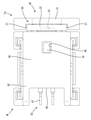
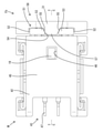
図11に示すように、本実施例2の保護部51は、ロックアーム15の操作部18を左右両側から挟むように一対、設けられている。各保護部51は、側面側保護部52と突起状保護部53とから構成されている。側面側保護部52は、端子収容部11の上面における後端部から上方(ロックアーム15側)へ立ち上がった形態である。突起状保護部53は、側面側保護部52の上端部から左右いずれかへ突出した形態である。左側の側面側保護部52の突起状保護部53は右方へ突出し、右側の側面側保護部52の突起状保護部53は左方へ突出している。即ち、一対の突起状保護部53は、互いに相手側の突起状保護部53に向かって突出した形態である。 As shown in FIG. 11, the protection portions 51 of the second embodiment are provided in pairs so as to sandwich the operation portions 18 of the lock arm 15 from both the left and right sides. Each protection portion 51 is composed of a side surface side protection portion 52 and a protrusion-shaped protection portion 53. The side surface side protection portion 52 is in a form of rising upward (on the lock arm 15 side) from the rear end portion on the upper surface of the terminal accommodating portion 11. The protruding protective portion 53 is in a form of projecting from the upper end portion of the side surface side protective portion 52 to either the left or right. The protruding protection portion 53 of the left side surface side protection portion 52 protrudes to the right, and the protrusion-like protection portion 53 of the right side surface side protection portion 52 protrudes to the left. That is, the pair of protruding protective portions 53 are in a form of projecting toward the protruding protective portions 53 on the opposite side of each other.

左右両突起状保護部53の対向面(即ち、保護部51の延出端部)同士の間には、嵌合空間54が確保されている。嵌合空間54は、上方、下方(操作部18側)、前方及び後方へ開放されている。互いに対向する左右一対の突起状保護部53の対向面が、受け部55としての機能を発揮する。左右両受け部55は、対向方向に対して斜め方向を向いた平面である。平面視における嵌合空間54(受け部55)の形状は、左右両受け部55の対向間隔が前方に向かって次第に狭まるような等脚台形をなしている。 A fitting space 54 is secured between the facing surfaces of the left and right protruding protective portions 53 (that is, the extending ends of the protective portions 51). The fitting space 54 is open upward, downward (on the operation unit 18 side), forward and backward. The facing surfaces of the pair of left and right protruding protective portions 53 facing each other exhibit the function as the receiving portion 55. The left and right receiving portions 55 are planes facing diagonally with respect to the facing direction. The shape of the fitting space 54 (receiving portion 55) in a plan view is an isosceles trapezoid in which the facing distance between the left and right receiving portions 55 gradually narrows toward the front.

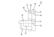
図9,10,13に示すように、リテーナ56には嵌込部57が一体に形成されている。嵌込部57は、壁部31の前面から前方へ片持ち状に延出した形態である。嵌込部57の左右方向における形成範囲は、受け部55(嵌合空間54)と対応する領域であり、リテーナ56(壁部31)の左右方向中央部である。嵌込部57の上下方向における形成範囲は、受け部55と概ね対応する領域である。嵌込部57は、壁部31の前面のうち操作孔34の開口縁の上縁部39から前方へ片持ち状に突出した形態である。嵌込部57の平面視形状は、一対の受け部55の間に確保された嵌合空間54と同じく等脚台形をなしている。 As shown in FIGS. 9, 10 and 13, the retainer 56 is integrally formed with the fitting portion 57. The fitting portion 57 has a cantilevered shape extending forward from the front surface of the wall portion 31. The formation range of the fitting portion 57 in the left-right direction is a region corresponding to the receiving portion 55 (fitting space 54) and the central portion in the left-right direction of the retainer 56 (wall portion 31). The formation range of the fitting portion 57 in the vertical direction is a region substantially corresponding to the receiving portion 55. The fitting portion 57 is in a form of cantilevering forward from the upper edge portion 39 of the opening edge of the operation hole 34 in the front surface of the wall portion 31. The plan view shape of the fitting portion 57 is an isosceles trapezoid like the fitting space 54 secured between the pair of receiving portions 55.

リテーナ56が雌側ハウジング50に対して適正に組み付けられると、図9に示すように、リテーナ56の嵌込部57が雌側ハウジング50の受け部55(嵌合空間54)に嵌合される。一対の受け部55の対向間隔は、前方(雌側ハウジング50に対するリテーナ56の組付け方向と同じ方向)に向かって次第に狭まるように変化するので、受け部55はガイド機能を発揮する。受け部55のガイド機能により、リテーナ56が、組付け過程において雌側ハウジング50に対して左右方向へ位置ずれしていても、嵌込部57の左右いずれかの側面が受け部55に摺接することにより、組付けが進むのに伴って位置ずれが矯正される。 When the retainer 56 is properly assembled to the female side housing 50, the fitting portion 57 of the retainer 56 is fitted into the receiving portion 55 (fitting space 54) of the female side housing 50 as shown in FIG. .. Since the facing distance between the pair of receiving portions 55 gradually narrows toward the front (the same direction as the assembly direction of the retainer 56 with respect to the female side housing 50), the receiving portions 55 exert a guide function. Due to the guide function of the receiving portion 55, even if the retainer 56 is displaced in the left-right direction with respect to the female side housing 50 in the assembling process, either the left or right side surface of the fitting portion 57 slides into contact with the receiving portion 55. As a result, the misalignment is corrected as the assembly progresses.

受け部55に嵌込部57が嵌合されると、雌側ハウジング50に対するリテーナ56の左右方向への相対変位が規制される。これにより、リテーナ56の壁部31が端子収容部11に対して適正な位置関係に保持されるので、壁部31に形成されている抜止め突起35と端子収容部11に収容されている雌端子金具24の二次係止部27も、適正な位置関係に保たれる。したがって、リテーナ56によって雌端子金具24を抜止めする機能の信頼性に優れている。 When the fitting portion 57 is fitted to the receiving portion 55, the relative displacement of the retainer 56 in the left-right direction with respect to the female side housing 50 is restricted. As a result, the wall portion 31 of the retainer 56 is held in an appropriate positional relationship with respect to the terminal accommodating portion 11, so that the retaining protrusion 35 formed on the wall portion 31 and the female housed in the terminal accommodating portion 11 are accommodated. The secondary locking portion 27 of the terminal fitting 24 is also maintained in an appropriate positional relationship. Therefore, the reliability of the function of retaining the female terminal fitting 24 by the retainer 56 is excellent.

平面視において、リテーナ56が雌側ハウジング50に対して斜め姿勢(即ち、不正な形態)で取り付けられた場合には、左右一対の弾性係止片36のうち一方の弾性係止片36の係止孔37が雌側ハウジング50の係止突起14に係止し、他方の弾性係止片36の係止孔37は係止突起14に係止しない状態となる。この場合、嵌込部57が受け部55に対して斜め姿勢で嵌入される。嵌合空間54は上方(雌側ハウジング50の外面側)へ開放されているので、受け部55と嵌込部57の嵌合状態は、雌側ハウジング50の外部上方から目視により確認することができる。 In a plan view, when the retainer 56 is attached to the female side housing 50 in an oblique posture (that is, in an improper form), the elastic locking piece 36 of one of the pair of left and right elastic locking pieces 36 is engaged. The stop hole 37 is locked to the locking projection 14 of the female side housing 50, and the locking hole 37 of the other elastic locking piece 36 is not locked to the locking projection 14. In this case, the fitting portion 57 is fitted in the receiving portion 55 in an oblique posture. Since the fitting space 54 is open upward (the outer surface side of the female side housing 50), the fitting state of the receiving portion 55 and the fitting portion 57 can be visually confirmed from above the outside of the female side housing 50. can.

本実施例2の雌側コネクタFbは、雌端子金具24が取り付けられる雌側ハウジング50と、雌側ハウジング50(端子収容部11)の後端部に取り付けられるリテーナ56とを備えて構成されている。雌側ハウジング50には、後端部がロック解除用の操作部18となっているロックアーム15が形成されている。雌側ハウジング50には、操作部18を覆う保護部51が形成されている。保護部51には受け部55が形成されている。リテーナ56には、リテーナ56が雌側ハウジング50に対して適正な形態で取り付けられたときにのみ、受け部55に嵌合される嵌込部57が形成されている。 The female side connector Fb of the second embodiment includes a female side housing 50 to which the female terminal fitting 24 is attached, and a retainer 56 attached to the rear end portion of the female side housing 50 (terminal accommodating portion 11). There is. The female side housing 50 is formed with a lock arm 15 having a rear end portion as an operation portion 18 for unlocking. The female side housing 50 is formed with a protective portion 51 that covers the operating portion 18. A receiving portion 55 is formed in the protective portion 51. The retainer 56 is formed with an fitting portion 57 that is fitted to the receiving portion 55 only when the retainer 56 is properly attached to the female side housing 50.

この構成によれば、リテーナ56が雌側ハウジング50に対して適正に取り付けられると、嵌込部57が受け部55に嵌合し、受け部55と嵌込部57との嵌合により、リテーナ56が雌側ハウジング50に対して位置決めされる。これにより、リテーナ56を雌側ハウジング50に対して適正な取付け状態に保持することができる。これにより、リテーナ56は所期の機能(雌端子金具24を抜止めする機能)を適正に発揮することができる。 According to this configuration, when the retainer 56 is properly attached to the female side housing 50, the fitting portion 57 is fitted to the receiving portion 55, and the fitting portion 55 and the fitting portion 57 are fitted to the retainer. 56 is positioned relative to the female housing 50. As a result, the retainer 56 can be held in a proper mounting state with respect to the female side housing 50. As a result, the retainer 56 can properly exert the desired function (the function of pulling out the female terminal fitting 24).

本実施例2の雌側コネクタFbは、一対の保護部51が、雌側ハウジング50の外面(端子収容部11の上面)から片持ち状に延出して操作部18を側方から挟むように配されている。そして、一対の保護部51の延出端部が、操作部18の上方において受け部55として機能する。嵌込部57は、一対の受け部55の間に嵌入されるようになっている。この構成によれば、受け部55と嵌込部57の嵌合状態を目視によって確認することができる。 In the female side connector Fb of the second embodiment, the pair of protective portions 51 extend cantileverly from the outer surface (upper surface of the terminal accommodating portion 11) of the female side housing 50 and sandwich the operation portion 18 from the side. It is arranged. Then, the extending end portion of the pair of protective portions 51 functions as a receiving portion 55 above the operating portion 18. The fitting portion 57 is adapted to be fitted between the pair of receiving portions 55. According to this configuration, the fitting state of the receiving portion 55 and the fitting portion 57 can be visually confirmed.

<実施例3>
次に、本発明を具体化した実施例3を図14~図20を参照して説明する。尚、以下の説明において、前後の方向については、図15~20における左方を前方と定義する。上下の方向については、図14,16,18,20にあらわれる向きを、そのまま上方、下方と定義する。
<Example 3>
Next, Example 3 which embodies the present invention will be described with reference to FIGS. 14 to 20. In the following description, the left side in FIGS. 15 to 20 is defined as the front in the front-back direction. Regarding the vertical direction, the directions appearing in FIGS. 14, 16, 18, and 20 are defined as upward and downward as they are.

本実施例3の雌側コネクタFc(請求項に記載のコネクタ)は、雌側ハウジング60の保護部61及び受け部64と、リテーナ67(請求項に記載の機能部品)の嵌込部68を上記実施例1とは異なる構成としたものである。その他の構成については上記実施例1及び実施例2と同じであるため、同じ構成については、同一符号を付し、構造、作用及び効果の説明は省略する。 The female side connector Fc (connector according to claim) of the third embodiment includes a protective portion 61 and a receiving portion 64 of the female side housing 60, and a fitting portion 68 of a retainer 67 (a functional component according to claim). The configuration is different from that of the first embodiment. Since other configurations are the same as those in the first and second embodiments, the same configurations are designated by the same reference numerals, and the description of the structure, action and effect will be omitted.

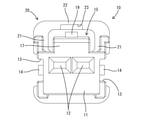
図16~18に示すように、本実施例3の保護部61は、実施例1と同様、左右一対の側面側保護部62と上面側保護部63とにより枠状に構成されている。左右一対の側面側保護部62は、端子収容部11の上面における後端部から上方(ロックアーム15側)へ立ち上がり、操作部18の左右両側面を覆うように配されている。上面側保護部63は、左右一対の側面側保護部62の上端部同士を連結した形態であり、操作部18の上面を覆うように配されている。保護部61は、操作部18に対する上方からの異物の干渉と、操作部18に対する左右両側方からの異物の干渉のみを防止する。保護部61及び雌側ハウジング60には、操作部18を後方から覆う部位は形成されていない。 As shown in FIGS. 16 to 18, the protection portion 61 of the third embodiment is configured in a frame shape by a pair of left and right side surface side protection portions 62 and an upper surface side protection portion 63, as in the first embodiment. The pair of left and right side protection portions 62 rise upward (on the lock arm 15 side) from the rear end portion on the upper surface of the terminal accommodating portion 11 and are arranged so as to cover the left and right side surfaces of the operation portion 18. The upper surface side protection portion 63 has a form in which the upper end portions of the pair of left and right side surface side protection portions 62 are connected to each other, and is arranged so as to cover the upper surface of the operation portion 18. The protection unit 61 prevents only the interference of foreign matter from above with respect to the operation unit 18 and the interference of foreign matter with the operation unit 18 from both the left and right sides. The protection portion 61 and the female side housing 60 are not formed with a portion that covers the operation portion 18 from the rear.

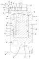
保護部61には、受け部64が一体に形成されている。受け部64は、上面側保護部63の左右方向における中央部、即ち左右方向において操作部18と対応する領域に配されている。受け部64は、上面側保護部63から前方へ片持ち状に延出した形態である。詳細には、受け部64は、上面側保護部63の後面から後方へ片持ち状に突出した平板状の基部65と、基部65の突出端縁から上方へ突出した突起部66とから構成されている。ロックアーム15の弾性変位方向、及び雌側ハウジング60に対するリテーナ67の取付け方向の両方向に対して直交する方向から見た形状を、側面視形状と定義する。受け部64の側面視形状は、略L字形に屈曲した形状である。 A receiving portion 64 is integrally formed with the protective portion 61. The receiving portion 64 is arranged in the central portion in the left-right direction of the upper surface side protection portion 63, that is, in the region corresponding to the operation portion 18 in the left-right direction. The receiving portion 64 is in a cantilevered form extending forward from the upper surface side protective portion 63. Specifically, the receiving portion 64 is composed of a flat plate-shaped base portion 65 protruding rearward from the rear surface of the upper surface side protective portion 63 in a cantilever shape, and a protruding portion 66 protruding upward from the protruding end edge of the base portion 65. ing. The shape seen from the direction orthogonal to both the elastic displacement direction of the lock arm 15 and the mounting direction of the retainer 67 with respect to the female side housing 60 is defined as a side view shape. The side view shape of the receiving portion 64 is a shape bent into a substantially L shape.

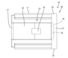
図19,20に示すように、リテーナ67には嵌込部68が一体に形成されている。嵌込部68は、壁部31のうち操作孔34の開口縁を構成する上縁部39の一部を凹ませた形態である。詳細には、嵌込部68は、操作孔34の上縁部39の下面における後縁部と、操作孔34の上縁部39の後面における下端縁部とを溝状に凹ませた形態である。換言すると、嵌込部68は、操作孔34の上縁部39の下方及び後方に開放された形態である。嵌込部68の左右方向における形成範囲は、受け部64と対応する領域であり、リテーナ67(壁部31)の左右方向中央部である。嵌込部68の上下方向における形成範囲は、受け部64の突起部66と概ね対応する領域である。リテーナ67を雌側ハウジング60に適正に取り付けた状態では、嵌込部68が受け部64の突起部66に嵌合される。 As shown in FIGS. 19 and 20, the retainer 67 is integrally formed with the fitting portion 68. The fitting portion 68 is a form in which a part of the upper edge portion 39 constituting the opening edge of the operation hole 34 is recessed in the wall portion 31. Specifically, the fitting portion 68 has a form in which the trailing edge portion on the lower surface of the upper edge portion 39 of the operation hole 34 and the lower end edge portion on the rear surface of the upper edge portion 39 of the operation hole 34 are recessed in a groove shape. be. In other words, the fitting portion 68 is in the form of being opened below and behind the upper edge portion 39 of the operation hole 34. The formation range of the fitting portion 68 in the left-right direction is a region corresponding to the receiving portion 64, and is a central portion in the left-right direction of the retainer 67 (wall portion 31). The formation range of the fitting portion 68 in the vertical direction is a region substantially corresponding to the protrusion 66 of the receiving portion 64. When the retainer 67 is properly attached to the female side housing 60, the fitting portion 68 is fitted to the protrusion 66 of the receiving portion 64.

図16に示すように、リテーナ67が雌側ハウジング60に対して適正に取り付けられると、嵌込部68が受け部64の突起部66に嵌合される。受け部64に対する嵌込部68の嵌合により、雌側ハウジング60に対するリテーナ67の後方への相対変位と、雌側ハウジング60に対するリテーナ67の左右方向への相対変位とが規制される。これにより、リテーナ67の壁部31が端子収容部11に対して適正な位置関係に保持されるので、壁部31に形成されている抜止め突起と端子収容部11に収容されている雌端子金具の二次係止部も、適正な位置関係に保たれる。したがって、リテーナ67によって雌端子金具を抜止めする機能の信頼性に優れている。 As shown in FIG. 16, when the retainer 67 is properly attached to the female side housing 60, the fitting portion 68 is fitted to the protrusion 66 of the receiving portion 64. The fitting of the fitting portion 68 with respect to the receiving portion 64 regulates the rearward displacement of the retainer 67 with respect to the female housing 60 and the lateral displacement of the retainer 67 with respect to the female housing 60. As a result, the wall portion 31 of the retainer 67 is held in an appropriate positional relationship with respect to the terminal accommodating portion 11, so that the retaining protrusion formed on the wall portion 31 and the female terminal accommodated in the terminal accommodating portion 11 The secondary locking portion of the metal fitting is also maintained in an appropriate positional relationship. Therefore, the retainer 67 is excellent in the reliability of the function of retaining the female terminal fitting.

平面視において、リテーナ67が雌側ハウジング60に対して斜め姿勢(即ち、不正な形態)で取り付けられた場合には、左右一対の弾性係止片のうち一方の弾性係止片の係止孔が雌側ハウジング60の係止突起に係止し、他方の弾性係止片の係止孔は係止突起に係止しない状態となる。この場合、嵌込部68が受け部64の突起部66よりも後方の位置に留まり、嵌込部68が受け部64の突起部66と嵌合できない。そのため、リテーナ67が雌側ハウジング60に対して相対変位し得る状態となり、雌側ハウジング60に対するリテーナ67の位置が安定しない。 In a plan view, when the retainer 67 is attached to the female housing 60 in an oblique posture (that is, in an improper form), the locking hole of one of the pair of left and right elastic locking pieces is the locking hole. Is locked to the locking protrusion of the female side housing 60, and the locking hole of the other elastic locking piece is not locked to the locking protrusion. In this case, the fitting portion 68 stays at a position behind the protrusion 66 of the receiving portion 64, and the fitting portion 68 cannot be fitted with the protrusion 66 of the receiving portion 64. Therefore, the retainer 67 can be displaced relative to the female housing 60, and the position of the retainer 67 with respect to the female housing 60 is not stable.

本実施例3の雌側コネクタFcは、雌端子金具が取り付けられる雌側ハウジング60と、雌側ハウジング60(端子収容部11)の後端部に取り付けられるリテーナ67とを備えて構成されている。雌側ハウジング60には、後端部がロック解除用の操作部18となっているロックアーム15が形成されている。雌側ハウジング60には、操作部18を覆う保護部61が形成されている。保護部61には受け部64が形成されている。リテーナ67には、リテーナ67が雌側ハウジング60に対して適正な形態で取り付けられたときにのみ、受け部64に嵌合される嵌込部68が形成されている。 The female connector Fc of the third embodiment includes a female housing 60 to which the female terminal fitting is attached, and a retainer 67 attached to the rear end of the female housing 60 (terminal accommodating portion 11). .. The female side housing 60 is formed with a lock arm 15 having a rear end portion as an operation portion 18 for unlocking. The female side housing 60 is formed with a protective portion 61 that covers the operating portion 18. A receiving portion 64 is formed in the protective portion 61. The retainer 67 is formed with an fitting portion 68 that is fitted to the receiving portion 64 only when the retainer 67 is properly attached to the female side housing 60.

この構成によれば、リテーナ67が雌側ハウジング60に対して適正に取り付けられると、嵌込部68が受け部64に嵌合し、受け部64と嵌込部68との嵌合により、リテーナ67が雌側ハウジング60に対して位置決めされる。これにより、リテーナ67を雌側ハウジング60に対して適正な取付け状態に保持することができる。これにより、リテーナ67は所期の機能(雌端子金具を抜止めする機能)を適正に発揮することができる。 According to this configuration, when the retainer 67 is properly attached to the female side housing 60, the fitting portion 68 is fitted to the receiving portion 64, and the retainer is fitted by fitting the receiving portion 64 and the fitting portion 68. 67 is positioned with respect to the female housing 60. As a result, the retainer 67 can be held in a proper mounting state with respect to the female side housing 60. As a result, the retainer 67 can properly exert the desired function (the function of pulling out the female terminal fitting).

また、リテーナ67が前後方向に貫通した形態の操作孔34(請求項に記載の開口部)を有し、操作孔34の開口縁部(上縁部)が嵌込部68となっている。保護部61は、雌側ハウジング60の外面(端子収容部11の上面)から枠状に延出して操作部18を囲む形態である。受け部64は、保護部61(上面側保護部63)から片持ち状に突出して操作孔34内に収容された状態で嵌込部68と嵌合する。この構成によれば、受け部64と嵌込部68の嵌合部分が操作孔34の内側に位置しているので、受け部64と嵌込部68との嵌合部分に異物が干渉する虞がない。 Further, the retainer 67 has an operation hole 34 (the opening according to claim) penetrating in the front-rear direction, and the opening edge portion (upper edge portion) of the operation hole 34 is the fitting portion 68. The protection portion 61 extends from the outer surface of the female side housing 60 (upper surface of the terminal accommodating portion 11) in a frame shape to surround the operation portion 18. The receiving portion 64 projects from the protective portion 61 (upper surface side protective portion 63) in a cantilever shape and fits with the fitting portion 68 in a state of being accommodated in the operation hole 34. According to this configuration, since the fitting portion between the receiving portion 64 and the fitting portion 68 is located inside the operation hole 34, there is a possibility that foreign matter may interfere with the fitting portion between the receiving portion 64 and the fitting portion 68. There is no.

<他の実施例>
本発明は上記記述及び図面によって説明した実施例に限定されるものではなく、例えば次のような実施例も本発明の技術的範囲に含まれる。
(1)上記実施例1~3では、リテーナ(機能部材)に覆い部を形成したが、リテーナ(機能部材)は覆い部を有しない形態であってもよい。
(2)上記実施例1~3では、嵌込部が覆い部に一体に形成されているが、嵌込部は覆い部とは別の部位に形成されていてもよい。
(3)上記実施例1~3では、機能部材が、端子金具を抜止めする機能を発揮するリテーナであるが、機能部材は、端子金具の抜止め機能とは異なる機能(例えば、ハウジングから導出した電線を屈曲させる電線カバーとしての機能)を発揮するものであってもよい。
<Other Examples>
The present invention is not limited to the examples described in the above description and drawings, and for example, the following examples are also included in the technical scope of the present invention.
(1) In the above-mentioned Examples 1 to 3, a cover portion is formed on the retainer (functional member), but the retainer (functional member) may be in a form having no cover portion.
(2) In Examples 1 to 3, the fitting portion is integrally formed with the covering portion, but the fitting portion may be formed at a portion different from the covering portion.
(3) In the above-described first to third embodiments, the functional member is a retainer that exerts a function of retaining the terminal fitting, but the functional member has a function different from the function of retaining the terminal fitting (for example, derived from the housing). It may exhibit a function as an electric wire cover for bending the electric wire.

Fa,Fb,Fc…雌側コネクタ(コネクタ)
10,50,60…雌側ハウジング(ハウジング)
15…ロックアーム
18…操作部
20,51…保護部
23,55,64…受け部
24…雌端子金具(端子金具)
30,56,67…リテーナ(機能部材)
33…覆い部
34…操作孔(開口部)
38,57,68…嵌込部
Fa, Fb, Fc ... Female side connector (connector)
10, 50, 60 ... Female side housing (housing)
15 ... Lock arm 18 ... Operation unit 20, 51 ... Protective unit 23, 55, 64 ... Receiving unit 24 ... Female terminal bracket (terminal bracket)
30, 56, 67 ... Retainer (functional member)
33 ... Cover 34 ... Operation hole (opening)
38, 57, 68 ... Fitting part

Claims (7)

端子金具が取り付けられるハウジングと、
前記ハウジングに形成され、後端部がロック解除用の操作部となっているロックアームと、
前記ハウジングに形成され、前記操作部を覆う保護部と、
前記ハウジングの後端部に取り付けられる機能部材と、
前記保護部に形成された受け部と、
前記機能部材に形成され、前記機能部材が前記ハウジングに対して適正な形態で取り付けられたときに前記受け部に嵌合可能な嵌込部とを備えていることを特徴とするコネクタ。
The housing to which the terminal fittings are attached and
A lock arm formed in the housing and whose rear end is an operation unit for unlocking,
A protective portion formed in the housing and covering the operation portion, and a protective portion.
A functional member attached to the rear end of the housing and
The receiving portion formed in the protective portion and
A connector formed on the functional member and comprising an fitting portion that is fitted to the receiving portion when the functional member is properly attached to the housing.
前記機能部材に形成され、前記操作部のうち前記保護部で覆われない領域を覆う覆い部を備えていることを特徴とする請求項1記載のコネクタ。 The connector according to claim 1, further comprising a covering portion formed on the functional member and covering a region of the operating portion that is not covered by the protective portion. 前記嵌込部が前記覆い部に一体に形成されていることを特徴とする請求項2記載のコネクタ。 The connector according to claim 2, wherein the fitting portion is integrally formed with the covering portion. 前記保護部が、前記ハウジングの外面から枠状に延出して前記操作部を囲む形態であり、
前記受け部が、前記保護部のうち前記操作部との対向面を凹ませた形態であり、
前記嵌込部が、前記機能部材から突出して前記保護部の内側に潜り込んた状態で前記受け部に嵌合するようになっていることを特徴とする請求項1ないし請求項3のいずれか1項に記載のコネクタ。
The protective portion extends from the outer surface of the housing in a frame shape to surround the operation portion.
The receiving portion has a shape in which the surface of the protective portion facing the operating portion is recessed.
One of claims 1 to 3, wherein the fitting portion is adapted to fit into the receiving portion in a state of protruding from the functional member and submerged inside the protection portion. The connector described in the section.
一対の前記保護部が、前記ハウジングの外面から片持ち状に延出して前記操作部を側方から挟むように配され、
前記一対の保護部の延出端部が、前記受け部として機能するようになっており、
前記嵌込部が、前記一対の受け部の間に嵌入されるようになっていることを特徴とする請求項1ないし請求項3のいずれか1項に記載のコネクタ。
A pair of the protective portions are arranged so as to extend cantilevered from the outer surface of the housing and sandwich the operation portion from the side.
The extending end portion of the pair of protective portions functions as the receiving portion.
The connector according to any one of claims 1 to 3, wherein the fitting portion is fitted between the pair of receiving portions.
前記機能部材が前後方向に貫通した形態の開口部を有し、
前記開口部の開口縁部が前記嵌込部となっており、
前記保護部が、前記ハウジングの外面から枠状に延出して前記操作部を囲む形態であり、
前記受け部が、前記保護部から片持ち状に突出して前記開口部内に収容された状態で前記嵌込部と嵌合するようになっていることを特徴とする請求項1ないし請求項3のいずれか1項に記載のコネクタ。
The functional member has an opening in the form of penetrating in the front-rear direction.
The opening edge of the opening serves as the fitting portion.
The protective portion extends from the outer surface of the housing in a frame shape to surround the operation portion.
The first to third aspects of the present invention, wherein the receiving portion is cantilevered from the protective portion and is accommodated in the opening so as to be fitted with the fitting portion. The connector according to any one item.
前記端子金具が前記ハウジングに対して後方から挿入されるようになっており、前記機能部材が、前記ハウジングの後端部に取り付けられることで、前記端子金具を抜止め状態に保持するリテーナであることを特徴とする請求項1ないし請求項6のいずれか1項に記載のコネクタ。 The terminal fitting is inserted from the rear with respect to the housing, and the functional member is attached to the rear end portion of the housing to hold the terminal fitting in a retaining state. The connector according to any one of claims 1 to 6, wherein the connector is characterized by the above.
JP2018240689A 2018-12-25 2018-12-25 connector Active JP6996487B2 (en)

Priority Applications (4)

Application Number Priority Date Filing Date Title
JP2018240689A JP6996487B2 (en) 2018-12-25 2018-12-25 connector
CN201980085419.2A CN113228426B (en) 2018-12-25 2019-12-06 Connector with a plurality of connectors
US17/413,430 US20220059962A1 (en) 2018-12-25 2019-12-06 Connector
PCT/JP2019/047871 WO2020137453A1 (en) 2018-12-25 2019-12-06 Connector

Applications Claiming Priority (1)

Application Number Priority Date Filing Date Title
JP2018240689A JP6996487B2 (en) 2018-12-25 2018-12-25 connector

Publications (2)

Publication Number Publication Date
JP2020102390A JP2020102390A (en) 2020-07-02
JP6996487B2 true JP6996487B2 (en) 2022-01-17

Family

ID=71127948

Family Applications (1)

Application Number Title Priority Date Filing Date
JP2018240689A Active JP6996487B2 (en) 2018-12-25 2018-12-25 connector

Country Status (4)

Country Link
US (1) US20220059962A1 (en)
JP (1) JP6996487B2 (en)
CN (1) CN113228426B (en)
WO (1) WO2020137453A1 (en)

Citations (1)

* Cited by examiner, † Cited by third party
Publication number Priority date Publication date Assignee Title
JP2009272104A (en) 2008-05-02 2009-11-19 Jst Mfg Co Ltd Electric connector with retainer

Family Cites Families (39)

* Cited by examiner, † Cited by third party
Publication number Priority date Publication date Assignee Title
JPH0235183Y2 (en) * 1985-05-01 1990-09-21
JP2563323Y2 (en) * 1990-10-22 1998-02-18 矢崎総業株式会社 connector
JP2585191Y2 (en) * 1991-03-26 1998-11-11 矢崎総業株式会社 Connector with terminal lock
JP2622221B2 (en) * 1992-03-10 1997-06-18 矢崎総業株式会社 Connector with terminal lock
US5507666A (en) * 1993-12-28 1996-04-16 Yazaki Corporation Lock securing mechanism for connectors
US5628648A (en) * 1995-03-17 1997-05-13 Molex Incorporated Electrical connector position assurance system
US5643003A (en) * 1995-06-02 1997-07-01 The Whitaker Corporation Housing latch with connector position assurance device
JP3301329B2 (en) * 1996-12-27 2002-07-15 住友電装株式会社 connector
JP3100927B2 (en) * 1997-08-25 2000-10-23 日本端子株式会社 Multi-pole connector retainer
US5947763A (en) * 1997-11-17 1999-09-07 General Motors Corporation Bi-directional staged CPA
JP3427782B2 (en) * 1999-05-28 2003-07-22 住友電装株式会社 connector
US6261116B1 (en) * 1999-11-22 2001-07-17 Yazaki North America, Inc. Connector position assurance element with lock protection feature
JP2001185290A (en) * 1999-12-27 2001-07-06 Sumitomo Wiring Syst Ltd Connector
JP2001291557A (en) * 2000-04-06 2001-10-19 Sumitomo Wiring Syst Ltd Connector
JP2002164125A (en) * 2000-11-27 2002-06-07 Sumitomo Wiring Syst Ltd Connector
US6435895B1 (en) * 2001-04-27 2002-08-20 Delphi Technologies, Inc. Connector position assurance device
JP3804554B2 (en) * 2002-03-13 2006-08-02 住友電装株式会社 connector
JP3991911B2 (en) * 2002-07-17 2007-10-17 住友電装株式会社 connector
JP3997858B2 (en) * 2002-07-24 2007-10-24 住友電装株式会社 Mating detection connector
TWI255592B (en) * 2002-08-23 2006-05-21 Hon Hai Prec Ind Co Ltd Electrical connector and method of making same
JP4168906B2 (en) * 2003-10-29 2008-10-22 住友電装株式会社 Split connector
JP2005190807A (en) * 2003-12-25 2005-07-14 Sumitomo Wiring Syst Ltd Connector
JP4175254B2 (en) * 2003-12-25 2008-11-05 住友電装株式会社 connector
US7238041B2 (en) * 2004-04-28 2007-07-03 Sumitomo Wiring Systems, Ltd. Connector
JP4385984B2 (en) * 2005-02-04 2009-12-16 住友電装株式会社 connector
JP4752606B2 (en) * 2006-05-15 2011-08-17 住友電装株式会社 connector
JP2008140571A (en) * 2006-11-30 2008-06-19 Sumitomo Wiring Syst Ltd Connector
JP5204469B2 (en) * 2007-11-30 2013-06-05 矢崎総業株式会社 Connector housing
US8747146B2 (en) * 2011-05-04 2014-06-10 Tyco Electronics Corporation Electrical connector having connector position assurance
JP2013101856A (en) * 2011-11-09 2013-05-23 Yazaki Corp Joint connector
JP5751196B2 (en) * 2012-03-09 2015-07-22 住友電装株式会社 connector
JP2014093222A (en) * 2012-11-05 2014-05-19 Sumitomo Wiring Syst Ltd Connector
US9281619B2 (en) * 2014-04-11 2016-03-08 Delphi Technologies, Inc. Vibration resistant connector system with connector position assurance device
JP6597287B2 (en) * 2015-12-24 2019-10-30 株式会社オートネットワーク技術研究所 Vehicle wiring system
JP6213590B2 (en) * 2016-02-25 2017-10-18 第一精工株式会社 connector
JP6402145B2 (en) * 2016-07-13 2018-10-10 矢崎総業株式会社 connector
JP6417369B2 (en) * 2016-07-29 2018-11-07 矢崎総業株式会社 connector
US10404012B1 (en) * 2018-04-20 2019-09-03 Te Connectivity Corporation Electrical connector with connector position assurance element
JP6865725B2 (en) * 2018-10-31 2021-04-28 矢崎総業株式会社 connector

Patent Citations (1)

* Cited by examiner, † Cited by third party
Publication number Priority date Publication date Assignee Title
JP2009272104A (en) 2008-05-02 2009-11-19 Jst Mfg Co Ltd Electric connector with retainer

Also Published As

Publication number Publication date
US20220059962A1 (en) 2022-02-24
CN113228426B (en) 2024-02-27
JP2020102390A (en) 2020-07-02
CN113228426A (en) 2021-08-06
WO2020137453A1 (en) 2020-07-02

Similar Documents

Publication Publication Date Title
JP5637023B2 (en) Dummy stopper
JP7348090B2 (en) connector assembly
JPH1041018A (en) Terminal fitting for short-circuit
JP5482220B2 (en) Locking structure of mating member in electrical junction box
JP7042402B2 (en) connector
JP2022107105A (en) Connector and connector device
JP4475122B2 (en) connector
JP6996487B2 (en) connector
JP2012054206A (en) Connector
JP2008218198A (en) Connector
JP7087986B2 (en) Split connector
JP7159807B2 (en) connector
WO2020071077A1 (en) Connector
WO2021166586A1 (en) Connector
JP7435373B2 (en) connector
JP2020155360A (en) connector
CN112688105B (en) Connector with a locking member
CN112563834B (en) Connector with a locking member
CN112563833B (en) Connector with a locking member
JP7389407B2 (en) card edge connector
JP7380496B2 (en) connector
JP7360886B2 (en) First connector, second connector, connector assembly
JP4029775B2 (en) connector
JP2023032558A (en) connector
CN116742392A (en) Connector with a plurality of connectors

Legal Events

Date Code Title Description
A621 Written request for application examination

Free format text: JAPANESE INTERMEDIATE CODE: A621

Effective date: 20210330

TRDD Decision of grant or rejection written
A01 Written decision to grant a patent or to grant a registration (utility model)

Free format text: JAPANESE INTERMEDIATE CODE: A01

Effective date: 20211116

A61 First payment of annual fees (during grant procedure)

Free format text: JAPANESE INTERMEDIATE CODE: A61

Effective date: 20211129

R150 Certificate of patent or registration of utility model

Ref document number: 6996487

Country of ref document: JP

Free format text: JAPANESE INTERMEDIATE CODE: R150