JP6606330B2 - Insulation structure for transformer, insulation method for transformer, and transformer provided with insulation structure - Google Patents
Insulation structure for transformer, insulation method for transformer, and transformer provided with insulation structure Download PDFInfo
- Publication number
- JP6606330B2 JP6606330B2 JP2015024838A JP2015024838A JP6606330B2 JP 6606330 B2 JP6606330 B2 JP 6606330B2 JP 2015024838 A JP2015024838 A JP 2015024838A JP 2015024838 A JP2015024838 A JP 2015024838A JP 6606330 B2 JP6606330 B2 JP 6606330B2
- Authority
- JP
- Japan
- Prior art keywords
- transformer
- winding
- preformed
- transformer core
- insulating structure
- Prior art date
- Legal status (The legal status is an assumption and is not a legal conclusion. Google has not performed a legal analysis and makes no representation as to the accuracy of the status listed.)
- Active
Links
- 238000009413 insulation Methods 0.000 title claims description 95
- 238000000034 method Methods 0.000 title description 30
- 238000004804 winding Methods 0.000 claims description 252
- 239000011810 insulating material Substances 0.000 claims description 18
- 239000000565 sealant Substances 0.000 claims description 14
- 238000004519 manufacturing process Methods 0.000 claims description 11
- 230000004907 flux Effects 0.000 claims description 6
- 239000011796 hollow space material Substances 0.000 claims description 5
- 238000001746 injection moulding Methods 0.000 claims description 5
- 239000012212 insulator Substances 0.000 claims 3
- 230000035515 penetration Effects 0.000 claims 1
- 239000011148 porous material Substances 0.000 claims 1
- 239000000463 material Substances 0.000 description 10
- 238000002347 injection Methods 0.000 description 7
- 239000007924 injection Substances 0.000 description 7
- 238000012986 modification Methods 0.000 description 5
- 230000004048 modification Effects 0.000 description 5
- 230000015572 biosynthetic process Effects 0.000 description 4
- 230000015556 catabolic process Effects 0.000 description 3
- 230000008878 coupling Effects 0.000 description 3
- 238000010168 coupling process Methods 0.000 description 3
- 238000005859 coupling reaction Methods 0.000 description 3
- 239000007789 gas Substances 0.000 description 3
- 238000002955 isolation Methods 0.000 description 3
- 238000005304 joining Methods 0.000 description 3
- 238000000465 moulding Methods 0.000 description 3
- 239000012815 thermoplastic material Substances 0.000 description 3
- 238000010276 construction Methods 0.000 description 2
- 238000004512 die casting Methods 0.000 description 2
- 239000003921 oil Substances 0.000 description 2
- 230000002093 peripheral effect Effects 0.000 description 2
- 230000008569 process Effects 0.000 description 2
- 229920001187 thermosetting polymer Polymers 0.000 description 2
- 230000007704 transition Effects 0.000 description 2
- 230000002411 adverse Effects 0.000 description 1
- 238000003780 insertion Methods 0.000 description 1
- 230000037431 insertion Effects 0.000 description 1
- 230000001788 irregular Effects 0.000 description 1
- 239000007788 liquid Substances 0.000 description 1
- 239000002994 raw material Substances 0.000 description 1
Images


Classifications
-
- H—ELECTRICITY
- H01—ELECTRIC ELEMENTS
- H01F—MAGNETS; INDUCTANCES; TRANSFORMERS; SELECTION OF MATERIALS FOR THEIR MAGNETIC PROPERTIES
- H01F27/00—Details of transformers or inductances, in general
- H01F27/28—Coils; Windings; Conductive connections
- H01F27/32—Insulating of coils, windings, or parts thereof
- H01F27/324—Insulation between coil and core, between different winding sections, around the coil; Other insulation structures
-
- H—ELECTRICITY
- H01—ELECTRIC ELEMENTS
- H01F—MAGNETS; INDUCTANCES; TRANSFORMERS; SELECTION OF MATERIALS FOR THEIR MAGNETIC PROPERTIES
- H01F17/00—Fixed inductances of the signal type
- H01F17/04—Fixed inductances of the signal type with magnetic core
- H01F17/06—Fixed inductances of the signal type with magnetic core with core substantially closed in itself, e.g. toroid
- H01F17/062—Toroidal core with turns of coil around it
-
- H—ELECTRICITY
- H01—ELECTRIC ELEMENTS
- H01F—MAGNETS; INDUCTANCES; TRANSFORMERS; SELECTION OF MATERIALS FOR THEIR MAGNETIC PROPERTIES
- H01F27/00—Details of transformers or inductances, in general
- H01F27/02—Casings
-
- H—ELECTRICITY
- H01—ELECTRIC ELEMENTS
- H01F—MAGNETS; INDUCTANCES; TRANSFORMERS; SELECTION OF MATERIALS FOR THEIR MAGNETIC PROPERTIES
- H01F27/00—Details of transformers or inductances, in general
- H01F27/28—Coils; Windings; Conductive connections
-
- H—ELECTRICITY
- H01—ELECTRIC ELEMENTS
- H01F—MAGNETS; INDUCTANCES; TRANSFORMERS; SELECTION OF MATERIALS FOR THEIR MAGNETIC PROPERTIES
- H01F27/00—Details of transformers or inductances, in general
- H01F27/28—Coils; Windings; Conductive connections
- H01F27/2823—Wires
-
- H—ELECTRICITY
- H01—ELECTRIC ELEMENTS
- H01F—MAGNETS; INDUCTANCES; TRANSFORMERS; SELECTION OF MATERIALS FOR THEIR MAGNETIC PROPERTIES
- H01F27/00—Details of transformers or inductances, in general
- H01F27/28—Coils; Windings; Conductive connections
- H01F27/2895—Windings disposed upon ring cores
-
- H—ELECTRICITY
- H01—ELECTRIC ELEMENTS
- H01F—MAGNETS; INDUCTANCES; TRANSFORMERS; SELECTION OF MATERIALS FOR THEIR MAGNETIC PROPERTIES
- H01F27/00—Details of transformers or inductances, in general
- H01F27/34—Special means for preventing or reducing unwanted electric or magnetic effects, e.g. no-load losses, reactive currents, harmonics, oscillations, leakage fields
- H01F27/346—Preventing or reducing leakage fields
-
- H—ELECTRICITY
- H01—ELECTRIC ELEMENTS
- H01F—MAGNETS; INDUCTANCES; TRANSFORMERS; SELECTION OF MATERIALS FOR THEIR MAGNETIC PROPERTIES
- H01F30/00—Fixed transformers not covered by group H01F19/00
- H01F30/06—Fixed transformers not covered by group H01F19/00 characterised by the structure
- H01F30/16—Toroidal transformers
-
- H—ELECTRICITY
- H01—ELECTRIC ELEMENTS
- H01F—MAGNETS; INDUCTANCES; TRANSFORMERS; SELECTION OF MATERIALS FOR THEIR MAGNETIC PROPERTIES
- H01F5/00—Coils
- H01F5/02—Coils wound on non-magnetic supports, e.g. formers
Landscapes
- Engineering & Computer Science (AREA)
- Power Engineering (AREA)
- Microelectronics & Electronic Packaging (AREA)
- Insulating Of Coils (AREA)
- Manufacturing Cores, Coils, And Magnets (AREA)
- Coils Of Transformers For General Uses (AREA)
- Coils Or Transformers For Communication (AREA)
Description
本発明は、変圧器のための予備成形した絶縁構造体、予備成形した絶縁構造体を備える変圧器及び予備成形した絶縁構造体を備える変圧器の製造方法に関する。かかる装置は、例えば一次コイル及び二次コイルの間に高圧が印加される変圧器に使用される。 The present invention relates to a preformed insulation structure for a transformer, a transformer comprising a preformed insulation structure, and a method for manufacturing a transformer comprising a preformed insulation structure. Such a device is used, for example, in a transformer in which a high voltage is applied between a primary coil and a secondary coil.
変圧器、特に絶縁変圧器は、変圧器コア及び少なくとも2本の巻線を内包できる。いくつかの絶縁変圧器では、巻線は二本巻き構造で巻回される。例示的な二本巻き構造を図1に示した。線材から形成される2本の巻線102、103は、環状の変圧器コア101の周囲に複数のコイル数だけ巻回される。2本の巻線102、103は、漏れインダクタンスを制限するために、例えば環状の変圧器コア101の略全周にわたって配置できる。第1の巻線102及び第2の巻線103の間の絶縁抵抗は、上記の構成では、巻線を構成する線材の間隔及び絶縁抵抗によって決定される。高圧、例えば1〜25kVの電圧に対して十分な絶縁抵抗を確保するために、線材の絶縁材料の厚み及び/又は線材同士の間隔を拡大できる。しかし、線材の間隔及び線材の絶縁材料の厚みの拡大は、コイルの体積を増大させるおそれがある。かかる線材についてなお同一となるコイル数を達成するために、より大型の変圧器コアを使用できる。この措置は、変圧器全体の寸法の大型化につながるおそれがある。
A transformer, in particular an isolation transformer, can contain a transformer core and at least two windings. In some isolation transformers, the winding is wound in a double winding structure. An exemplary twin winding structure is shown in FIG. The two
別の例では、変圧器の2本の巻線は、環状の変圧器コアの周上のそれぞれ異なる円弧上に巻回できる(例えば120度の円弧)。これによって、第1及び第2の巻線の間の間隔を拡大できる。しかし、第1及び第2の巻線のかかる構成によって、漏れインダクタンスが増大し、更に変圧器コアの一部にはコイルが全く巻回されないため、変圧器コア及び変圧器全体の寸法の大型化という結果をもたらすおそれがある。 In another example, the two windings of the transformer can be wound on different arcs on the circumference of the annular transformer core (eg, a 120 degree arc). As a result, the distance between the first and second windings can be increased. However, such a configuration of the first and second windings increases the leakage inductance, and further, no coil is wound around a part of the transformer core, so that the dimensions of the transformer core and the entire transformer are increased. May result.
第1の予備成形した絶縁構造体は、第1及び第2の巻線を変圧器の変圧器コアの周囲に巻回した場合に変圧器の第1及び第2の巻線の間に位置するように設計され、上記予備成形した絶縁構造体は、第2の巻線が第1の巻線及び変圧器コアから離間するように設計される。 The first preformed insulation structure is located between the first and second windings of the transformer when the first and second windings are wound around the transformer core of the transformer. The pre-formed insulation structure is designed such that the second winding is spaced from the first winding and the transformer core.
第2の予備成形した絶縁構造体は、第1及び第2の巻線を変圧器の変圧器コアの周囲に巻回した場合に、第1及び第2のコイルと変圧器の変圧器コアとの間に位置するように設計され、上記予備成形した絶縁構造体は、第1及び第2の巻線が変圧器コアから離間するように設計される。 The second pre-formed insulation structure includes first and second coils and a transformer core when the first and second windings are wound around the transformer core of the transformer. And the pre-formed insulation structure is designed such that the first and second windings are spaced from the transformer core.
第1の変圧器は、変圧器コア、第1の巻線を構成する第1の線材及び第2の巻線を構成する第2の線材を含み、第1及び第2の巻線は変圧器コアの周囲に巻回され、変圧器は、第1又は第2の予備成形した絶縁構造体を更に含む。 The first transformer includes a transformer core, a first wire constituting the first winding, and a second wire constituting the second winding, the first and second windings being transformers Wrapped around the core, the transformer further includes a first or second preformed insulating structure.
予備成形した絶縁構造体を使用することで、容易に製造できるコンパクトな変圧器を構成できる。予備成形した絶縁構造体はその寸法によって、第1及び第2の巻線の間の最小間隔を画定する。このようにして、絶縁構造体によって第1及び第2の巻線の間の電気的耐圧の最小値を確実に画定する。特に、第1及び第2の巻線を2つの異なる平面に配置できる。かかる配置によってコンパクトな構成を確保でき、同時にかかる構成の漏れインダクタンスを小さい値に抑制できる。絶縁構造体が予備成形されている(従ってかかる絶縁構造体が組み付けられる変圧器内で取ることになる形状を、組み付けられていない状態でも略安定的に維持できる)ことから、変圧器の組み立てが容易になる。例えば第2の巻線を、予備成形した絶縁構造体の周囲に直接巻回できる。 By using a pre-formed insulating structure, a compact transformer that can be easily manufactured can be constructed. The preformed insulating structure defines the minimum spacing between the first and second windings by its dimensions. In this way, the insulation structure ensures that the minimum value of the electrical breakdown voltage between the first and second windings is defined. In particular, the first and second windings can be arranged in two different planes. With this arrangement, a compact configuration can be secured, and at the same time, the leakage inductance of the configuration can be suppressed to a small value. Since the insulation structure is pre-formed (thus, the shape to be taken in the transformer in which such an insulation structure is assembled can be maintained substantially stably even in the unassembled state). It becomes easy. For example, the second winding can be wound directly around the preformed insulating structure.
第1の変圧器の条件も含む第2の変圧器では、第2の巻線は、予備成形した絶縁構造体の周囲に巻回される。 In the second transformer, which also includes the conditions of the first transformer, the second winding is wound around a pre-formed insulating structure.
第1又は第2の変圧器の条件も含む第3の変圧器では、予備成形した絶縁構造体は、その周囲に第2の線材が巻回されている場合、形状が略安定する。 In the third transformer including the conditions of the first or second transformer, the shape of the preformed insulating structure is substantially stabilized when the second wire is wound around it.
第1〜第3の変圧器のいずれか1つの条件も含む第4の変圧器では、予備成形した絶縁構造体は1部品構成である。 In the fourth transformer including any one condition of the first to third transformers, the preformed insulating structure has a one-part configuration.
第4の変圧器の条件も含む第5の変圧器では、予備成形した絶縁構造体は、変圧器コア又は第1の巻線を装着した変圧器コアの少なくとも一部を取り囲むように設計されたシェルを含む。 In the fifth transformer, which also includes the conditions of the fourth transformer, the pre-formed insulation structure was designed to surround at least a portion of the transformer core or the transformer core fitted with the first winding. Includes a shell.
第1〜第3の変圧器のいずれか1つの条件も含む第6の変圧器では、予備成形した絶縁構造体は多部品構成である。 In the sixth transformer including the conditions of any one of the first to third transformers, the pre-formed insulating structure has a multi-part configuration.
第6の変圧器の条件も含む第7の変圧器では、予備成形した絶縁構造体は、変圧器コア又は第1の巻線を装着した変圧器コアの少なくとも一部を取り囲むように設計された第1及び第2のシェルを含む。 In the seventh transformer, which also includes the conditions of the sixth transformer, the pre-formed insulation structure was designed to surround at least a portion of the transformer core or the transformer core fitted with the first winding. Includes first and second shells.
第7の変圧器の条件も含む第8の変圧器では、第1及び第2のシェルは同一形状に成形される。 In the eighth transformer including the conditions of the seventh transformer, the first and second shells are formed in the same shape.
第1〜第8の変圧器のいずれか1つの条件も含む第9の変圧器では、予備成形した絶縁構造体は、変圧器コア又は第1の巻線を装着した変圧器コアの全体を取り囲むように設計される。 In the ninth transformer including any one of the conditions of the first to eighth transformers, the preformed insulating structure surrounds the entire transformer core or the transformer core fitted with the first winding. Designed as such.
第6〜第9の変圧器のいずれか1つの条件も含む第10の変圧器では、予備成形した絶縁構造体は3以上の部品を含む。 In the tenth transformer including any one condition of the sixth to ninth transformers, the preformed insulating structure includes three or more parts.
第1〜第10の変圧器のいずれか1つの条件も含む第11の変圧器では、予備成形した絶縁構造体は1つ又は複数の孔を備える。 In the eleventh transformer including any one of the conditions of the first to tenth transformers, the pre-formed insulating structure includes one or more holes.
第11の変圧器の条件も含む第12の変圧器では、孔は円形、三角形、矩形又は多角形とするか、或いは不規則な形状を有する。 In the twelfth transformer, which also includes the conditions of the eleventh transformer, the holes are circular, triangular, rectangular or polygonal, or have an irregular shape.
第11又は第12の変圧器の条件も含む第13の変圧器では、予備成形した絶縁構造体は10を上回る数の孔を備える。 In the thirteenth transformer, which also includes the conditions of the eleventh or twelfth transformer, the preformed insulation structure comprises more than ten holes.
第11〜第13の変圧器のいずれか1つの条件も含む第14の変圧器では、1つ又は複数の孔は、予備成形した絶縁構造体の表面の10%を超える部分を占める。 In the fourteenth transformer including any one of the conditions of the first to thirteenth transformers, the one or more holes occupy more than 10% of the surface of the preformed insulating structure.
第11〜第14の変圧器のいずれか1つの条件も含む第15の変圧器では、1つ又は複数の孔は、変圧器コア及び第1の巻線が予備成形した絶縁構造体の内部に設置された状態では、変圧器コア又は変圧器コア及び第1の巻線が占めていないスペースの全体が、1つ又は複数の孔を介して外部スペースと流体結合するように設計される。 In the fifteenth transformer including any one of the conditions of the first to fourteenth transformers, the one or more holes are formed inside the insulating structure pre-formed by the transformer core and the first winding. In the installed state, the transformer core or the entire space not occupied by the transformer core and the first winding is designed to be fluidly coupled to the external space through one or more holes.
先行する変圧器のいずれか1つの条件も含む第16の変圧器では、変圧器は、更に、変圧器コア、第1及び第2の巻線並びに予備成形した絶縁構造体を収容するように設計されたハウジングを含む。 In the sixteenth transformer, which also includes the conditions of any one of the preceding transformers, the transformer is further designed to accommodate a transformer core, first and second windings, and a pre-formed insulating structure. Housing.
第16の変圧器の条件も含む第17の変圧器は、ハウジングの内部に絶縁物質を更に含む。 The seventeenth transformer, which also includes the conditions of the sixteenth transformer, further includes an insulating material inside the housing.
第17の変圧器の条件も含む第18の変圧器では、絶縁物質は、封止剤、オイル又はガスの中から選択される。 In the 18th transformer, which also includes the conditions of the 17th transformer, the insulating material is selected from among sealants, oils or gases.
第16〜第18の変圧器のいずれか1つの条件も含む第19の変圧器では、予備成形した絶縁構造体の1つ又は複数の孔は、変圧器コア、第1及び第2の巻線、並びに第1及び第2のシェルがハウジング内に設置された状態で、中空スペースを形成せずにハウジングの内部スペースを絶縁物質で充填できるように配置される。 In a nineteenth transformer that also includes any one of the conditions of the sixteenth to eighteenth transformers, the one or more holes in the pre-formed insulation structure may include the transformer core, the first and second windings. The first and second shells are disposed in the housing so that the inner space of the housing can be filled with an insulating material without forming a hollow space.
第16〜第19の変圧器のいずれか1つの条件も含む第20の変圧器では、ハウジングは、予備成形した絶縁構造体をハウジングの1つ又は複数の外壁と離間するように、1つ又は複数の突起を備える。 In a twentieth transformer that also includes any one of the conditions of the sixteenth to nineteenth transformers, the housing has one or more such that the preformed insulating structure is spaced from one or more outer walls of the housing. A plurality of protrusions are provided.
先行する変圧器のいずれか1つの条件も含む第21の変圧器では、予備成形した絶縁構造体は閉鎖面を規定する。 In the twenty-first transformer, which also includes the conditions of any one of the preceding transformers, the preformed insulating structure defines a closure surface.
第21の変圧器の条件も含む第22の変圧器では、予備成形した絶縁構造体からなる閉鎖面の1つ又は複数の辺は、変圧器コア及び第1の巻線に対して開かれている。 In the 22nd transformer, which also includes the conditions of the 21st transformer, one or more sides of the closure surface of the pre-formed insulation structure are open to the transformer core and the first winding. Yes.
第21又は第22の変圧器のいずれか1つの条件も含む第23の変圧器では、予備成形した絶縁構造体はトロイド形状を有する。 In the twenty-third transformer, which also includes any one condition of the twenty-first or twenty-second transformer, the preformed insulating structure has a toroid shape.
先行する変圧器のいずれか1つの条件も含む第24の変圧器では、予備成形した絶縁構造体は移行部を規定し、この移行部によって、第2の線材を変圧器コアの周囲に巻回できる。 In the twenty-fourth transformer, including any one of the conditions of the preceding transformer, the pre-formed insulation structure defines a transition, by which the second wire is wound around the transformer core. it can.
先行する変圧器のいずれか1つの条件も含む第25の変圧器では、変圧器コアは、閉じた形状を有する。 In the 25th transformer, which also includes the conditions of any one of the preceding transformers, the transformer core has a closed shape.
先行する変圧器のいずれか1つの条件も含む第26の変圧器では、第1及び/又は第2の巻線は、変圧器コアに沿って少なくとも300°の範囲を占める。 In a twenty-sixth transformer that also includes the conditions of any one of the preceding transformers, the first and / or second windings occupy a range of at least 300 ° along the transformer core.
第25又は第26の変圧器のいずれか1つの条件も含む第27の変圧器では、変圧器コアはトロイドである。 In the twenty-seventh transformer, which also includes the conditions of either the twenty-fifth or twenty-sixth transformer, the transformer core is a toroid.
第27の変圧器の条件も含む第28の変圧器では、変圧器コアは環状である。 In the twenty-eighth transformer, including the twenty-seventh transformer condition, the transformer core is annular.
先行する変圧器のいずれか1つの条件も含む第29の変圧器では、第1及び/又は第2の巻線は、変圧器コアに沿って少なくとも175°の範囲を占める。 In the twenty-ninth transformer, which also includes the conditions of any one of the preceding transformers, the first and / or second windings occupy a range of at least 175 ° along the transformer core.
第30の変圧器の条件も含む第31の変圧器は、第3の巻線を構成する第3の線材を含み、第3のコイルは変圧器コアの周囲に巻回される。 The 31st transformer including the condition of the 30th transformer includes the third wire constituting the third winding, and the third coil is wound around the transformer core.
第30又は第31の変圧器の条件も含む第32の変圧器では、予備成形した絶縁構造体は、1つ又は複数の他の巻線を構成する1つ又は複数の他の線材を含み、1つ又は複数の他の巻線は変圧器コアの周囲に巻回される。 In the 32nd transformer, which also includes the conditions of the 30th or 31st transformer, the pre-formed insulation structure includes one or more other wires that constitute one or more other windings; One or more other windings are wound around the transformer core.
第32の変圧器の条件も含む第33の変圧器では、第1の巻線は、変圧器コアに沿って少なくとも300°の範囲を占め、第2の巻線及び1つ又は複数の他の巻線は、それぞれ変圧器コアの異なった部分を占め、互いに離間している。 In the 33rd transformer, which also includes the conditions of the 32nd transformer, the first winding occupies a range of at least 300 ° along the transformer core, the second winding and one or more other The windings occupy different parts of the transformer core and are spaced apart from each other.
第33の変圧器の条件も含む第34の変圧器では、変圧器は、他の第1の巻線を含み、かかる他の第1の巻線は、変圧器コアに沿って少なくとも300°の範囲を占め、第1の巻線と共に1つの平面上に巻回される。 In a thirty-fourth transformer, which also includes the thirty-third transformer condition, the transformer includes another first winding that is at least 300 ° along the transformer core. Occupies a range and is wound on a plane with the first winding.
先行する変圧器のいずれか1つの条件も含む第35の変圧器では、第1の巻線は一次巻線であり、第2の巻線及び他の巻線は二次巻線である。 In a thirty-fifth transformer that also includes any one condition of the preceding transformer, the first winding is a primary winding, and the second and other windings are secondary windings.
先行する変圧器のいずれか1つの条件も含む第36の変圧器では、変圧器コアは第1の平面を規定し、この第1の平面内又はこの第1の平面と平行に、変圧器の動作中に磁束が流れ、予備成形した絶縁構造体が第1及び第2の巻線の間に設けられることで、第2の巻線が、第1の平面と垂直に伸びる第2の方向では、第1の巻線及び変圧器コアと離間される。 In a thirty-sixth transformer that also includes the conditions of any one of the preceding transformers, the transformer core defines a first plane, and in or parallel to the first plane of the transformer. Magnetic flux flows during operation and a pre-formed insulating structure is provided between the first and second windings so that the second winding extends in a second direction perpendicular to the first plane. , Spaced apart from the first winding and the transformer core.
先行する変圧器のいずれか1つの条件も含む第37の変圧器では、予備成形した絶縁構造体は射出成形法によって製造される。 In a thirty-seventh transformer that also includes any one of the preceding transformer conditions, the preformed insulation structure is manufactured by an injection molding process.
先行する変圧器のいずれか1つの条件も含む第38の変圧器では、予備成形した絶縁構造体は熱可塑性材料を含む。 In a thirty-eighth transformer that also includes the conditions of any one of the preceding transformers, the pre-formed insulating structure includes a thermoplastic material.
先行する変圧器のいずれか1つの条件も含む第39の変圧器では、予備成形した絶縁構造体は、0〜10MHzでの誘電率が1〜10である材料を含む。 In a thirty-ninth transformer that also includes any one condition of the preceding transformer, the preformed insulating structure includes a material having a dielectric constant of 1 to 10 at 0 to 10 MHz.
第39の変圧器の条件も含む第40の変圧器では、第2及び第3の巻線の間に予備成形した絶縁構造体が設置され、かかる絶縁構造体は、第3の巻線を第2の巻線、第1のコイル及び変圧器コアから離間させる。 In the 40th transformer, which also includes the conditions of the 39th transformer, a pre-formed insulation structure is installed between the second and third windings, and the insulation structure connects the third winding to the third winding. Separated from the second winding, the first coil and the transformer core.
先行する変圧器のいずれか1つの条件も含む第41の変圧器では、予備成形した絶縁構造体は1つ又は複数の線材ホルダを含み、かかる線材ホルダに、第1、第2の線材又はその両者、更に選択的に他の線材のそれぞれを固定できる。 In the forty-first transformer including any one condition of the preceding transformer, the preformed insulating structure includes one or a plurality of wire rod holders, and the wire rod holder includes the first, second wire rods or the Both can further selectively fix each of the other wires.
第18の変圧器又は第18の変圧器及び先行する変圧器のいずれか1つの変圧器の条件も含む第42の変圧器では、予備成形した絶縁構造体は、1つ又は複数の位置決め構造体を含み、かかる位置決め構造体は、予備成形した絶縁構造体をハウジング内部の1つ又は複数の方向では位置決めするよう設計される。 In the forty-second transformer, which also includes the conditions of any one of the eighteenth transformer or the eighteenth transformer and the preceding transformer, the pre-formed insulating structure is one or more positioning structures. Such a positioning structure is designed to position the preformed insulating structure in one or more directions inside the housing.
第42の変圧器の条件も含む第43の変圧器では、1つ又は複数の位置決め構造体は突起を含み、かかる突起は、予備成形した絶縁構造体の表面に設けられる。 In the forty-third transformer, which also includes the conditions for the forty-second transformer, the one or more positioning structures include protrusions that are provided on the surface of the pre-formed insulating structure.
第42又は第43の変圧器の条件も含む第44の変圧器では、突起は、第2の巻線とハウジングの1つ又は複数の側面との間隔が一定となるような寸法とする。 In the forty-fourth transformer, including the conditions of the forty-second or forty-third transformer, the protrusions are dimensioned so that the spacing between the second winding and one or more sides of the housing is constant.
先行する変圧器のいずれか1つの条件も含む第45の変圧器では、予備成形した絶縁構造体及びハウジングは同一の材料からなる。 In the forty-fifth transformer including the conditions of any one of the preceding transformers, the preformed insulating structure and the housing are made of the same material.
第9又は先行する変圧器のいずれか1つの変圧器の条件も含む第46の変圧器では、変圧器コアは第1の平面を規定し、この第1の平面内又はこの第1の平面と平行に、変圧器の動作中に磁束が流れ、変圧器コアの上側及び下側は第1の平面と平行に広がり、第1のシェルが変圧器コアの上側を、第2のシェルが変圧器コアの下側をそれぞれ取り囲む。 In a forty-sixth transformer, which also includes the conditions of any one of the ninth or preceding transformers, the transformer core defines a first plane, and within this first plane or with this first plane In parallel, magnetic flux flows during operation of the transformer, the upper and lower sides of the transformer core extend parallel to the first plane, the first shell is above the transformer core, and the second shell is the transformer. Surround the underside of each core.
第9の変圧器又は第9の変圧器及び先行する変圧器のいずれか1つの変圧器の条件も含む第47の変圧器では、変圧器コアは第1の平面を規定し、この第1の平面内又はこの第1の平面と平行に、変圧器の動作中に磁束が流れ、変圧器コアの第1のハーフ及び第2のハーフを区分する第2の平面は、第1の平面と垂直な位置にあり、第1のシェルが変圧器コアの第1のハーフを、第2のシェルが変圧器コアの第2のハーフをそれぞれ取り囲む。 In the 47th transformer, which also includes the condition of any one of the ninth transformer or the ninth transformer and the preceding transformer, the transformer core defines a first plane, and this first A magnetic flux flows during operation of the transformer in or parallel to the first plane, and the second plane that separates the first half and the second half of the transformer core is perpendicular to the first plane. The first shell surrounds the first half of the transformer core and the second shell surrounds the second half of the transformer core.
先行する変圧器のいずれか1つの変圧器の条件も含む第48の変圧器では、予備成形した絶縁構造体は、第1の線材、第2の線材又はその両者の巻回補助具を有する。 In the forty-eighth transformer including the conditions of any one of the preceding transformers, the pre-formed insulating structure has a winding aid for the first wire, the second wire, or both.
第3の予備成形した絶縁構造体は、変圧器コアの一部を取り囲むよう設計された第1のシェルを含み、この第1のシェルは、複数の孔及び第1のキャビティを含む。更に、第3の予備成形した絶縁構造体は、変圧器コアの一部を取り囲むよう設計された第2のシェルを含み、この第2のシェルは、複数の孔及び第2のキャビティを含む。第1及び第2のシェルは、第1及び第2のシェルが変圧器コアを取り囲んでいる状態で、第1及び第2のキャビティによって線材を変圧器コアの周囲に巻回できるように設計される。 The third preformed insulating structure includes a first shell designed to surround a portion of the transformer core, the first shell including a plurality of holes and a first cavity. In addition, the third preformed insulation structure includes a second shell designed to surround a portion of the transformer core, the second shell including a plurality of holes and a second cavity. The first and second shells are designed such that the wire can be wound around the transformer core by the first and second cavities, with the first and second shells surrounding the transformer core. The
第1の変圧器の製造方法は、変圧器コアを提供するステップ及び第1の巻線を形成するために第1の線材を変圧器コアの周囲に巻回するステップを含み、更に、予備成形した絶縁構造体が、第1の巻線及び変圧器コアの少なくとも一部を取り囲むように、予備成形した絶縁構造体を設置するステップを含み、更に、第2の巻線を形成するために、第2の線材を予備成形した絶縁構造体の周囲に巻回するステップを含む。 The method of manufacturing the first transformer includes the steps of providing a transformer core and winding a first wire around the transformer core to form a first winding, and further preforming Placing the preformed insulation structure so that the insulated structure surrounds at least a portion of the first winding and the transformer core, and further, to form the second winding, Winding a second wire around a pre-formed insulating structure.
第1の方法の条件も含む第2の方法では、第2の巻線を、第1の巻線及び変圧器コアから離間させる。 In the second method, which also includes the conditions of the first method, the second winding is separated from the first winding and the transformer core.
第1又は第2の方法の条件も含む第3の方法は、更に、第1及び第2の巻線並びに予備成形した絶縁構造体を装着した変圧器コアをハウジング内に設置するステップを含み、更に、絶縁材料でハウジングを充填するステップを含み、予備成形した絶縁構造体は、中空スペースを形成せずに、ハウジングを充填できる。 The third method, which also includes the conditions of the first or second method, further includes the step of installing in the housing a transformer core fitted with the first and second windings and the preformed insulation structure; Further, the method includes filling the housing with an insulating material so that the preformed insulating structure can fill the housing without forming a hollow space.
第2又は第3の方法の条件も含む第4の方法では、ハウジングを充填するステップは、低圧下で行われる。 In the fourth method, which also includes the conditions of the second or third method, the step of filling the housing is performed under low pressure.
第2、第3又は第4の方法の条件も含む第5の方法では、ハウジングを充填するステップは、ダイキャスト法を含む。 In the fifth method, which also includes the conditions of the second, third or fourth method, the step of filling the housing includes a die casting method.
先行する方法のいずれか1つの条件も含む第6の方法では、予備成形した絶縁構造体は、1つ又は複数の線材ホルダを含み、上記の方法は、更に、第2の線材を予備成形した絶縁構造体の周囲に巻回するステップに先立って、第2の線材の第1の部分を線材ホルダに固定するステップを含み、更に、第2の線材を予備成形した絶縁構造体の周囲に巻回した後に、第2の線材の第2の部分を線材ホルダに固定するステップを含む。 In a sixth method that also includes any one of the conditions of the preceding method, the pre-formed insulating structure includes one or more wire holders, and the above method further pre-forms the second wire. Prior to the step of winding around the insulating structure, the method includes a step of fixing the first portion of the second wire to the wire holder, and further winding the second wire around the insulating structure that has been preformed. After turning, the method includes a step of fixing the second portion of the second wire rod to the wire rod holder.
先行する方法のいずれか1つの条件も含む第7の方法は、更に、第1の巻線を装着した変圧器コアを予備成形した絶縁構造体の第1のシェルに嵌め込むステップを含み、更に、第1の線材の1つ又は複数の部分を固定するステップを含む。更に、上記の方法は、第1の線材の1つ又は複数の部分を固定した後に、第1のシェルを予備成形した絶縁構造体の第2のシェルに結合するステップを含む。 The seventh method, including the conditions of any one of the preceding methods, further comprises the step of fitting a transformer core fitted with the first winding into the first shell of the pre-formed insulation structure; , Fixing one or more portions of the first wire. Further, the method includes the step of bonding the first shell to the second shell of the pre-formed insulating structure after securing one or more portions of the first wire.
限定的でも包括的でもない本発明の実施形態について、以下の図面を参照して説明する。同一の符号は、別途記載のない限りにおいて、異なる図面中でも同一の部品を指す。 Embodiments of the present invention that are neither limiting nor comprehensive will be described with reference to the following drawings. The same reference numerals refer to the same parts in different drawings unless otherwise specified.
以下の説明において、本発明の理解を深められるよう、数多くの詳細を記載する。しかし、本発明に変更を加える上で、これら個々の詳細が不可欠ではないことは、当業者には明らかである。他の箇所では、本発明の理解を不必要に困難にすることのないよう、従来公知の装置及び方法については細部にわたって説明しない。 In the following description, numerous details are set forth to provide a thorough understanding of the present invention. However, it will be apparent to one skilled in the art that these individual details are not essential in making modifications to the invention. In other places, well-known devices and methods are not described in detail so as not to unnecessarily complicate the understanding of the present invention.
以下の説明では、「ある実施形態」、「ある形態」、「ある実施例」又は「実施例」に関する言及は、当該実施形態に関連して説明される一定の技術的特徴、構成又は特性が、本発明の少なくとも1つの実施形態に含まれることを意味する。従って、以下の説明の様々な箇所に見られる「ある実施形態において」、「ある形態において」、「ある実施例」又は「ある実施例において」という語句全てが、当該実施形態又は当該実施例そのものに関するとは限らない。更に、一定の技術的特徴、構成又は特性は、1つ又は複数の実施形態又は実施例中で、任意の組み合わせ及び/又は部分組み合わせで組み合わせることができる。特定の技術的特徴、構成又は特性は、集積回路、電子回路、回路論理、又は説明されている機能を提供するその他の適当な部品に含まれるものとすることができる。更に、図面は当業者に対する説明を目的としたものであり、実際の寸法に忠実に示されたものではないことを指摘しておく。 In the following description, references to “an embodiment,” “an embodiment,” “an example,” or “an example” refer to certain technical features, configurations, or characteristics described in connection with the embodiment. , Is meant to be included in at least one embodiment of the present invention. Accordingly, the phrases “in an embodiment”, “in an embodiment”, “in an embodiment”, or “in an embodiment” appearing in various places in the description below refer to the embodiment or the embodiment itself. It doesn't have to be. Furthermore, certain technical features, configurations, or characteristics may be combined in any combination and / or subcombination in one or more embodiments or examples. Certain technical features, configurations or characteristics may be included in integrated circuits, electronic circuits, circuit logic, or other suitable components that provide the functions described. Further, it should be pointed out that the drawings are for the purpose of illustration to those skilled in the art and are not shown to scale with actual dimensions.
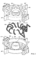
図2〜4は、予備成形した絶縁構造体をさまざまな角度から見た図を示す。ここで、予備成形した絶縁構造体は、第2の巻線203を第1の巻線202及び変圧器コア201から離間させるよう設計される。第1の巻線202及び第2の巻線203は、それぞれ1つ又は複数のコイルを含む。あるいは、以下に示す予備成形した絶縁構造体は、変圧器コアのみを取り囲む形とすることで、第1及び第2の巻線を変圧器コアから離間させてもよい。例示的な予備成形した絶縁構造体は2部品構成であり、第1のシェル204及び第2のシェル205からなる。変圧器コア201は、第1の線材から形成される第1の巻線202を貫通する。言い換えると、第1の巻線202は、変圧器コア201の周囲に巻回される。このような関係は、第1の巻線202及び変圧器コア201のみならず、以上及び以下の記載において巻線を特定の部材に巻回する状況について論じる場合全てに広く適用される。第1のシェル204及び第2のシェル205は、変圧器コア201及び第1の巻線202の一部を取り囲む(別の実施例では、変圧器コアのみを取り囲む)ように組み付けできる。図3は、第1のシェル204及び第2のシェル205の組み合わされた状態を示す。この実施例では、第1のシェル204及び第2のシェル205は、変圧器コア201及び第1の巻線202の一部の筒状の収容部を形成する。しかし、第1のシェル204及び第2のシェル205によって形成される収容部の筒状の形状は必須ではない。それゆえ、収容部は、他のさまざまな形状であってよい(例えば収容部をトーラスの形状としてよい)。この条件は、2部品構成の絶縁構造体のみならず、1部品構成の絶縁構造体又は3つ以上の部品から構成される絶縁構造体にも該当する。
2-4 show views of the preformed insulating structure from various angles. Here, the pre-formed insulating structure is designed to separate the second winding 203 from the first winding 202 and the
更に、図4に見る通り、第1のシェル204及び第2のシェル205は、第2の線材を第1のシェル204及び第2のシェル205の周囲に巻回できるように設計される。これによって、第2の巻線203が形成される。このために、第1のシェル204及び第2のシェル205は、図2〜4の実施例では、選択的な内壁214を形成する。しかし、内壁214は、省略することもできる。これらの実施例では、第2の線材は、絶縁構造体の上側210及び下側211の間に密巻される。更に、第2の巻線203は、内壁214によって形成された孔を貫通して、上側210及び下側211の間に巻回される。
Furthermore, as seen in FIG. 4, the
第1のシェル204及び第2のシェル205、第1の巻線202及び第2の巻線203並びに変圧器コア201は、絶縁変圧器を形成できる。図4に示した通り、シェル204、205は、第1の巻線202及び第2の巻線203の所定の最小間隔を確保する。かかる最小間隔から、装置の最小耐電圧(この値は、第1のシェル204及び第2のシェル205が製造される際に原料となる材料の材料特性によって決定される)が得られる。こうして、多くの実施例では、第1のシェル204及び第2のシェル205を備え予備成形した絶縁構造体が使用されない変圧器に比較して、線材の絶縁層を薄くできる(多くの実施例では、絶縁膜を備えた線材も使用できる)。この結果として、線材の直径を小さくし、線材の柔軟性を向上でき、このことから巻線の巻回が容易にできる。更に、第1及び第2の巻線の間隔を前もって正確に決定できる。こうして、不要な絶縁材料の投入が少なくて済むため、全体の構造のコンパクトさを維持できる。図2〜4に見る通り、絶縁構造体をコンパクトかつ簡略化した構成としたにもかかわらず、第1及び第2の線材は、変圧器コアの略全体に巻回できる。かかる措置によって、漏れインダクタンスを低減できる。
The
図2〜4に示した装置は、2部品構成の絶縁構造体を備える。しかし、2部品構成とした実施形態は必須ではない。別の実施例では、予備成形した絶縁構造体は略筒状であり、第1の巻線を装着した変圧器コアの挿入のための開口部を具備できる。かかる開口部は、筒状の絶縁構造体の側壁に設置できる。この代わりに、1部品構成の予備成形した絶縁構造体は、単一のシェルから構成できる。第1の巻線を密巻した環状コアを単一のシェルに挿入できるとしたことで、第1の巻線及び予備成形した絶縁構造体のシェルの側壁の上縁部の間に、十分な間隔が発生する。第2の巻線は、1部品構成の絶縁構造体の周囲に密巻される。 The apparatus shown in FIGS. 2 to 4 includes an insulating structure having a two-part configuration. However, the two-part embodiment is not essential. In another embodiment, the pre-formed insulation structure is generally cylindrical and may include an opening for insertion of a transformer core fitted with a first winding. Such an opening can be installed on the side wall of the cylindrical insulating structure. Alternatively, a one-piece pre-formed insulation structure can be constructed from a single shell. Since the annular core having the first winding tightly wound can be inserted into a single shell, there is sufficient space between the first winding and the upper edge of the side wall of the shell of the preformed insulation structure. An interval occurs. The second winding is closely wound around the one-part insulating structure.
別の実施例では、予備成形した絶縁構造体は多部品構成であってよい。例えば図2〜4のシェルの各々が、2つ以上の部品から構成できる。 In another embodiment, the pre-formed insulating structure may be a multi-part configuration. For example, each of the shells of FIGS. 2-4 can be composed of two or more parts.
予備成形した絶縁構造体の形状に関しては、多様な変更形態が検討される。図2〜4に示した例では、第1のシェル204及び第2のシェル205は、変圧器コア201及び第1の巻線202の部分を、全ての面から完全に取り囲む。ここで、図2〜4に示した予備成形した絶縁構造体は、変圧器コア201及び第1の巻線202の一部の略筒状の収容部を構成する。シェル204、205は、それぞれ筒状の収容部の円形の上側210又は下側211及び周囲の側壁209を構成する。
Various modifications are considered for the shape of the pre-formed insulating structure. In the example shown in FIGS. 2-4, the
別の実施例では、第1のシェル204及び第2のシェル205は、筒状の収容部の円形の上側210又は下側211のみを形成できる。周囲の側壁209は、(一部又は全体を)省略できる。図3、4に対応する図では、かかる収容部に変圧器コア(の一部)が確認できる。しかし、かかる収容部では、第2の巻線が第1のコイル及び変圧器コアから確実に離間している状態を確保できる。それゆえ、筒状の収容部の円形の上側又は下側を通過する形で第2の線材を密巻でき、もって、予備成形した絶縁構造体が、変圧器コアの全体を取り囲んでいないとしても、第1の巻線(第1の巻線自体は変圧器コアの周囲に密巻できる)の変圧器コアの周囲部分と所定の間隔を維持する。たった今説明された配置は、筒状の収容部に限定されない。側壁209の全体を省略する代わりに、絶縁構造体の形状安定性を改善するために、1つ又は複数の支持要素を提供できる。例えば上側210又は下側211の縁部に、支持ストラットを設置できる。
In another embodiment, the
別の実施例では、筒状の収容部の上側210又は下側211の一部又は全体を省略できる。図3、4に対応する図では、かかる収容部に変圧器コア(の一部)が確認できる。かかる収容部でも、第2の巻線が第1のコイル及び変圧器コアから確実に離間している状態を確保できる。かかる絶縁構造体では、周囲を囲む側壁209、内壁214及び上側210又は下側211の周囲に第2の線材を密巻できる。たった今説明された配置についても、筒状の収容部に限定されない。
In another embodiment, a part or the whole of the
図2〜4に示したシェルは、確かに収容部の上側210又は下側211を構成する。しかし、かかる上側210又は下側211には、複数の孔206(かかる孔については、以下に詳細に説明する)が貫通している。それゆえ、図2〜4に示したシェルの周囲の、孔206の部分では、できる限り孔206の下方に巻回された第1の巻線との間に所定の間隔が維持されるように、かかる孔の上を通過して第2の巻線を巻回できる。上側210又は下側211を完全に省略する代わりに、絶縁構造体の形状安定性を向上させるために、1つ又は複数の支持要素を設置できる。例えば上側210又は下側211の縁部に、支持スポークを設置できる。
The shells shown in FIGS. 2 to 4 certainly constitute the
図2〜4に示した絶縁構造体は、選択的な1つ又は複数のコネクタを備え、かかるコネクタは、それぞれほぞ212及びほぞを収容するほぞ穴213を含む。ここで、ほぞ212は、シェル204、205の一方に設けられ、対応するほぞ穴213は、それぞれ他方のシェル204、205に設けられる。ほぞ212及びほぞ穴213を備えるコネクタに代えて、2つのシェル204、205を結合する他のあらゆる結合要素を使用できる。例えば互いにスナップ結合する構造体又は第1及び第2のシェルをヒンジ結合するヒンジを提供できる。結合要素の配置は、絶縁構造体の2つ以上の部品が全て1つの方法又は複数の同等の方法で結合できるように選択できる。図2〜4の実施例では、シェル204、205の2箇所には、2組のほぞ/ほぞ穴を配置し、別の2箇所には、1組のほぞ/ほぞ穴のみを配置したことで、シェル204、205は、2つの方法のみによって組み合わせできる条件が確保される。これによって、シェル(その他の多部品構成の絶縁構造体)が間違って組み合わせられ、間違いを解消するために、必要に応じて第2の巻線を取り外さなければならなくなる事態を回避できる。
The insulation structure shown in FIGS. 2-4 includes an optional connector or connectors, each including a
図2〜4を用いて、ここまで数頁では、予備成形した絶縁構造体が変圧器コアを収容し、第2の巻線を第1の巻線及び変圧器コアから離間させるための方法について説明してきた。以下において、図5を用いて、図2〜4に示したシェル204、205の他の選択的な技術的特徴が説明される。しかし、かかる技術的特徴は、シェルを備える2部品構成の絶縁構造体に限定されない。むしろ、他の絶縁構造体にも使用できる。
With reference to FIGS. 2 to 4, so far in a few pages, a method for the pre-formed insulation structure to accommodate the transformer core and to separate the second winding from the first winding and the transformer core. I have explained. In the following, FIG. 5 will be used to describe other optional technical features of the
図5に見る通り、絶縁構造体は、1つ又は複数の線材ホルダ208a、208bを具備できる。図5の実施例では、2つの線材ホルダ208a、208bは、第1のシェル204及び第2のシェル205の対向する側に設置される。第1の線材ホルダ208aは、第1の巻線202の第1の端部202a及び第2の端部202bを固定するように設計される。図5の実施例では、第1の巻線202の第1の端部202a及び第2の端部202bは、第1の線材ホルダ208aの通路に挟まれて固定できる。予備成形した絶縁構造体は、第1の巻線202の第1の端部202a及び第2の端部202bを予備成形した絶縁構造体の内側から外側にガイドするためにガイド(図5では見えない)を含む。
As seen in FIG. 5, the insulating structure can comprise one or
同様に、第2の巻線203の第1の端部203a及び第2の端部203bは、第2の線材ホルダ208bの通路に挟まれて固定できる。第1の巻線202及び第2の巻線203を固定することで、第1及び第2の巻線の巻回後に第1及び第2の巻線の位置が変わることを防止できる。特に、第2の線材が、組み合わされた状態の第1のシェル204及び第2のシェル205の上から巻回される場合には、上記の措置は、巻回ステップを簡略化できる。それゆえ、まず、第2の巻線203の第1の端部203aを、ホルダ208bに固定できる。その後、第2の巻線203の残りの線材を巻回して、最後に第2の巻線203の第2の端部203bをホルダ208bに固定する。こうして、線材が巻回ステップ中に反発力で戻るか又は線材の位置が変わることを回避できる。
Similarly, the
図2〜5に示した装置では、線材ホルダ208は2つの部品からなり、この部品は1つずつ、第1のシェル204又は第2のシェル205に設置される。別の実施例では、線材ホルダは1部品構成としてよく、及び/又は絶縁構造体の一部に設置してよい。更に、図2〜5に示した線材ホルダ208はそれぞれ、それぞれの線材の2つの端部を固定するように設計されている。別の実施例では、線材のそれぞれの端部に固有の線材ホルダを提供できる。更に、それぞれの線材を1箇所又は3箇所以上で固定できる。線材が固定される箇所は、必ずしもそれぞれの線材の端部としなくともよい。例えば図5の第2の線材には、4つの線材ホルダを提供でき、これらの線材ホルダは、絶縁構造体の周に沿って均等に配置される。更に、線材ホルダ208は、挟持通路(図5参照)に代えて、他の固定要素を具備できる。それゆえ、保持装置は、線材が固定されている第1の位置及び線材が固定されていない第2の位置の間で移動可能な要素を具備できる。
In the apparatus shown in FIGS. 2 to 5, the
直前で説明した通り、予備成形した絶縁構造体は、1つ又は複数の線材を固定するための線材ホルダを具備できる。更に又はあるいは、予備成形した絶縁構造体に巻回補助具(例えばキャビティ又は突起)を設置でき、かかる巻回補助具上又はこの内部に、第1及び/又は第2の線材(図5には図示せず)を配置できる。ある実施例では、第1のシェル204及び第2のシェル205は、上側210又は下側211に複数の突起を備え、巻回時には、かかる複数の突起に第2の線材を配置できる。
As described immediately above, the pre-formed insulating structure can include a wire holder for securing one or more wires. Additionally or alternatively, a winding aid (e.g., cavity or protrusion) can be placed on the preformed insulating structure and the first and / or second wires (as shown in FIG. 5) on or within the winding aid. (Not shown) can be arranged. In one embodiment, the
次に、図6〜8を用いて、予備成形した絶縁構造体の他の選択的な技術的特徴及びハウジング内の予備成形した絶縁構造体の配置について説明する。図を必要以上に複雑にしないよう、予備成形した絶縁構造体並びに第1及び/又は第2の巻線は、図2〜5に示した要素に一致する。しかし、図6〜8を用いて説明した選択的な技術的特徴は、他の絶縁構造体(例えば1部品構成又は多部品構成の絶縁構造体)も備える形でも使用できる。 Next, other optional technical features of the preformed insulation structure and the arrangement of the preformed insulation structure in the housing will be described with reference to FIGS. In order not to complicate the figure more than necessary, the pre-formed insulation structure and the first and / or second windings correspond to the elements shown in FIGS. However, the optional technical features described with reference to FIGS. 6-8 can also be used with other insulation structures (eg, one-part or multi-part insulation structures).
図6では、図4の絶縁構造体に一致する、2つのシェル204、205からなる予備成形した絶縁構造体を図示した。この絶縁構造体は、第1の巻線202及び第2の巻線203を備える。更に、図6では、対応するハウジング301を示し、このハウジングは、第1の巻線202及び第2の巻線203、変圧器コア201並びに第1のシェル204及び第2のシェル205からなる予備成形した絶縁構造体を収容するように設計されている。この目的で、ハウジングは、十分な寸法とした内部スペースを構成する。更に、ハウジング301は、選択的な止め具304を備え、この止め具に第1の巻線202及び第2の巻線203の端部が固定され、この止め具が変圧器から外部への接点となる。図6の実施例では、止め具304は、ハウジング301の外面305に設置された突起303に配置される。更に、止め具304及び突起303がハウジング301の対向する位置に配置された例を示す。第1及び第2の巻線の端部を、ハウジング301内で、ハウジング301の内部スペースから外側に向かってガイドを用いてガイドした上で、この位置で固定できる。図6では、裸線(すなわち線材端部の絶縁シースが除去された線材)が止め具304の周囲に巻回される。しかし、止め具304の他の形態も実施可能である。
In FIG. 6, a preformed insulating structure consisting of two
ハウジングは、回路内(例えばプリント基板上)に設置できる。この目的で、図6の実施例では、ハウジングはネジ用のアイレット302又は同様の固定具を備える。
The housing can be placed in a circuit (eg on a printed circuit board). For this purpose, in the embodiment of FIG. 6, the housing comprises a
予備成形した絶縁構造体もハウジング301も、予備成形した絶縁構造体のハウジング301への配置及び固定が容易になるか又はかかる作業ができるようにする他の技術的特徴を選択的に具備できる。次に、かかる技術的特徴について、図7を用いて詳細に説明する。
Both the preformed insulation structure and the
すでに図2〜6に見た通り、予備成形した絶縁構造体は、1つ又は複数の突起207を具備でき、かかる突起は、予備成形した絶縁構造体の外壁に配置される。図7の実施例では、第1のシェル204及び第2のシェル205は、それぞれ2つずつの突起207a、207bを備える。ハウジング301は、これに対応するノッチ307a、307bを備える。図7の実施例では、ノッチ307a、307bは、固定されていない4つの壁面要素309a〜309dから形成され、これらの壁面要素は、ハウジング301の上側からハウジング301の内部スペースまで延びている。ノッチ307a、307b及び突起207a、207bは、突起207a、207bがノッチ307a、307bに係合するように、予備成形した絶縁構造体が第1の巻線202及び第2の巻線203並びに変圧器コア201と共にハウジング301内に挿入できるような配置及び寸法とする。こうして、予備成形した絶縁構造体の位置、更には第1及び第2の巻線並びに変圧器コアの位置を、ハウジング301内の図7の投影面上で画定できる。特に、予備成形した絶縁構造体とハウジング301の周囲の側壁との間隔及び予備成形した絶縁構造体の回転角を画定できる。予備成形した絶縁構造体とハウジング側壁との間隔の方は、予備成形した絶縁構造体更には第1及び第2の巻線とハウジング301の周囲の側壁との間隔から、変圧器の外部に対する耐電圧が規定されることから有利となり得る。突起207a、207b及びノッチ307a、307bを用いて、予備成形した絶縁構造体、第1及び第2の巻線とハウジング301の周囲の側壁との間で、略等間隔とした間隔を達成できる。これによって、絶縁破壊が発生する可能性がある弱点の形成を防止できる。この結果、変圧器をよりコンパクトに設計できる。というのは、絶縁破壊防止のために提供すべき追加の絶縁材料が、全く必要ないか又は従来に比べて少なくて済むからである。ハウジング301内部での予備成形した絶縁構造体の回転角の調節によって、変圧器の組み立てが簡略化できる。図7に示した通り、第1及び第2の巻線の線材端部が、かかる線材端部をハウジング301の壁面を伝って外部へとガイドできる箇所に横たわっている。
As already seen in FIGS. 2-6, the pre-formed insulating structure can comprise one or
ハウジング301内部での予備成形した絶縁構造体の位置決め機能は、図7に示した突起207a、207b及びノッチ307a、307bとは別の位置決め構造体を用いても達成できる。例えばハウジング301の内壁309a〜309dを省略できる。予備成形した絶縁構造体とハウジング301の周囲の側壁との間隔は、この実施例では、ハウジング301の周囲の側壁に直接接触できる予備成形した絶縁構造体の突起のみによって調節できる。あるいは、ノッチ307a、307bと同様に作用するノッチをハウジング301の周囲の側壁内に直接設置できる。こうすることでも、ハウジング301内部での予備成形した絶縁構造体の回転角が調節できる。突起の形状も変更できる。図7(更には先行するいくつかの図)では、2つの対向する位置の突起が提供される。突起の数及び/又は位置も、これと異なってよい。例えば別の実施例では、3以上の突起を設置できる。ある実施例では、予備成形した絶縁構造体の位置決めのために、対応するノッチ内で挟持できる1つの突起を提供できる。あるいは又は更に、予備成形した絶縁構造体の他の要素を、ハウジング301内部での位置決めのために使用できる。ある実施例では、線材ホルダを、予備成形した絶縁構造体とハウジング301の周囲の側壁(その少なくとも一部)との間隔を画定するような形状としてよい。
The positioning function of the preformed insulating structure inside the
図7の突起207a、207b及びノッチ307a、307bは、第1の平面における予備成形した絶縁構造体の位置及び回転角を画定できる。更に図7では、ハウジング301が多数の突起308を備えることが確認できる。かかる突起308は、予備成形した絶縁構造体とハウジング301の下側(「下側」という語は、図7に示した配置との関連で見た相対的なものであり、下側の面法線は、直前で定義された第1の平面に垂直である)との間隔を画定する。別の実施例では、予備成形した絶縁構造体(例えば第1及び/又は第2のシェル204、205)は、予備成形した絶縁構造体とハウジングの下側との間の間隔を取るために、1つ又は複数の突起を備える。
The
図8は、図6、7に示した変圧器の部品が組み立てられた状態の斜視図を示す。予備成形した絶縁構造体222は、選択的に、図7との関連で説明された位置決め補助具を用いてハウジング301の内部で位置決めされる。ここで、変圧器の絶縁耐圧を高め、巻線及び変圧器コアを外部と分離するために、封止剤をハウジング内に注入できる。封止剤の注入を容易に行うために、予備成形した絶縁構造体は、複数の孔206を備える。かかる孔は、孔206によって中空スペースが形成されることなく、予備成形した絶縁構造体222によって形成される内部スペースを充填できるように配置できる。この実施例では、第1のシェル204及び第2のシェル205は、それぞれ多数の孔を備える。結果として、例示的な絶縁物質とされるのは、封止剤である。しかし、本明細書で説明した予備成形した絶縁構造体との関連で、他の絶縁物質も使用できる。例えば絶縁性液体(例えば絶縁油)又は絶縁ガスを使用できる。
FIG. 8 is a perspective view showing a state where the components of the transformer shown in FIGS. 6 and 7 are assembled. The preformed insulating
第1のシェル204及び第2のシェル205は、第1のシェル204及び第2のシェル205が組み合わされたときに、他の孔が発生するような寸法としてよい。例えば図10では、第1のシェル204及び第2のシェル205が組み合わされた場合の、縦長のエアギャップ910の形成が確認できる。かかる縦長のエアギャップによって、第1のシェル204及び第2のシェル205の充填時の封止剤の流動挙動を改善できる。
The
図2〜8では、第1のシェル204及び第2のシェル205の上側及び下側に設けた孔206は円形である。しかし、かかる形状は必須ではない。同様に、孔は必ずしも予備成形した絶縁構造体の対向する位置にある2つの側(例えば上側210及び下側211)に設けられなくともよい。予備成形した絶縁構造体の上側及び下側は、スポーク状に設けられたバーのみを含むことで、弓形の孔を形成できる。別の実施例では、孔は矩形、六角形又は楕円形であってよい。ただし、孔の大きさ、形状及び位置は、封止剤が孔を通過して予備成形した絶縁構造体の内部スペースに浸入できるように配慮しなければならない。予備成形した絶縁構造体の上側、下側又は側壁が省略された例では、かかる措置によって発生する開口部は、予備成形した絶縁構造体の内部スペースを封止剤で充填するのに十分なものとすることができる。目的に適した孔を提供することで、予備成形した絶縁構造体の内部スペースを封止剤で確実に充填できる。特に、内部スペースに気泡が形成された場合には、特に絶縁耐圧、一般的には変圧器の絶縁特性に悪影響を与えることがあるが、かかる内部スペースの気泡形成を回避できる。
2-8, the
今度は、図9、10を用いて、予備成形した絶縁構造体の製法及びその材料特性の更なる詳細について説明する。図9、10でも、図2〜8に示した、2つのシェルからなる予備成形した絶縁構造体が確認できる。しかし、以下の説明も、この特殊な実施形態に限定されない。むしろ、本明細書中で論じた全ての予備成形した絶縁構造体を、提案される製法を用いて以下に論じる材料特性のもとで製造できる。 This time, FIGS. 9 and 10 will be used to describe the details of the manufacturing method of the preformed insulating structure and its material properties. 9 and 10, the pre-formed insulating structure composed of two shells shown in FIGS. 2 to 8 can be confirmed. However, the following description is not limited to this special embodiment. Rather, all of the preformed insulating structures discussed herein can be manufactured using the proposed process and under the material properties discussed below.
ある実施例では、予備成形した絶縁構造体は、射出成型法を用いて製造される。こうして、予備成形した絶縁構造体を特に安価に製造できる。図9、10に見る通り、予備成形した絶縁構造体は、2つの部品のみから構成できる。ハウジング内部での予備成形した絶縁構造体の位置決めのための1つ又は複数の位置決め構造体、線材ホルダ及び予備成形した絶縁構造体の異なる部品の結合のためのコネクタを、第1及び第2の巻線の離間のための部品と一体に形成できる。それゆえ、図9、10の絶縁構造体は、第1の射出成型品901及び第2の射出成型品902を包含できる。ここで、第1の射出成型品901及び第2の射出成型品902はそれぞれ、一体とした位置決め構造体907(突起ともいう)、線材ホルダ908及びコネクタ909を備える。ここで、図9に示した特殊な要素のみならず、図2〜8との関連で列記された変更形態も、第1及び第2の巻線の離間のための部品と一体に形成できる。同様のことは、1つ又は3つ以上の部品を含む予備成形した絶縁構造体にも当てはまる。例えばハウジング内部での予備成形した絶縁構造体の位置決めのための位置決め構造体907、線材ホルダ及び予備成形した絶縁構造体の異なる部品の結合のためのコネクタを、予備成形した絶縁構造体の複数の部品のうちの1つと一体に形成できる。
In one embodiment, the pre-formed insulating structure is manufactured using an injection molding process. In this way, a pre-formed insulating structure can be manufactured particularly inexpensively. As seen in FIGS. 9 and 10, the pre-formed insulation structure can consist of only two parts. One or more positioning structures for positioning the preformed insulation structure within the housing, a wire holder and a connector for joining different parts of the preformed insulation structure, the first and second It can be formed integrally with a part for separating the windings. Therefore, the insulating structure of FIGS. 9 and 10 can include a first injection molded
更に図9から分かる通り、絶縁構造体は、2つの同一形状に成型した部品(例えば2つの同一形状に成型したシェル)からなる。別の実施例では、絶縁構造体は、2つの同一形状に成型した部品(例えば2つのシェル)を含む。こうして、予備成形した絶縁構造体の製造コストを更に低減できる。というのは、必要となる射出成型金型の数(又は他の成型法に必要となる金型の数)が抑えられるからである。 Further, as can be seen from FIG. 9, the insulating structure is composed of two parts molded in the same shape (for example, two shells molded in the same shape). In another embodiment, the insulating structure includes two identically shaped parts (eg, two shells). Thus, the manufacturing cost of the preformed insulating structure can be further reduced. This is because the number of injection molds required (or the number of molds required for other molding methods) can be reduced.
射出成型法との関連での以上の説明は、他の成型法を用いた製法にも当てはまる。図2〜10で説明した部品は、かかる成型法を用いた代替的な製法でも製造できる。 The above explanation in relation to the injection molding method also applies to the manufacturing method using other molding methods. The parts described in FIGS. 2 to 10 can be manufactured by an alternative manufacturing method using such a molding method.
本明細書中で説明した変圧器のハウジングは、予備成形した絶縁構造体と同一の製法で製造できる。例えばハウジング及び1部品又は多部品構成の予備成形した絶縁構造体の全ての部品を射出成型法で製造できる。更に又はあるいは、ハウジング及び予備成形した絶縁構造体の部品が、ハウジングと同一の材料から構成できる。こうして、かかる部品を内包する変圧器の製造コストを更に低減できる。別の実施例では、予備成形した絶縁構造体の1つ又は複数の部品を、ハウジングと結合できる。こうして、かかる部品を、ハウジングと同時に(例えば射出成型品として)製造できる。ある実施例では、予備成形した絶縁構造体は2つのシェルからなり、シェルのうちの1つがハウジングと結合され、ハウジングと同時に射出成型品として製造される。2つ目のシェルは、別の射出成型品とするか、又はハウジングと結合できる。 The transformer housing described herein can be manufactured in the same manner as the preformed insulation structure. For example, all parts of a housing and a pre-formed insulating structure of one-part or multi-part construction can be manufactured by injection molding. Additionally or alternatively, the housing and the pre-formed parts of the insulating structure can be constructed from the same material as the housing. In this way, the manufacturing cost of the transformer containing such components can be further reduced. In another embodiment, one or more parts of the pre-formed insulating structure can be coupled with the housing. In this way, such a part can be manufactured simultaneously with the housing (eg as an injection-molded product). In one embodiment, the pre-formed insulation structure consists of two shells, one of which is joined to the housing and manufactured as an injection molded product at the same time as the housing. The second shell can be another injection molded product or can be joined to the housing.
ある実施例では、予備成形した絶縁構造体の部品(例えば図2〜10のシェル)は、熱可塑性材料を含む(熱可塑性材料からなる)。予備成形した絶縁構造体の部品(例えば図2〜10のシェル)は、熱硬化性材料を含む(熱硬化性材料からなる)。上述の通り、予備成形した絶縁構造体が埋め込まれるハウジングは、予備成形した絶縁構造体と同一の材料から構成できる。 In some embodiments, the pre-formed part of the insulating structure (eg, the shell of FIGS. 2-10) comprises a thermoplastic material (consists of a thermoplastic material). A preformed part of the insulating structure (eg, the shell of FIGS. 2-10) includes a thermosetting material (consisting of a thermosetting material). As described above, the housing in which the preformed insulating structure is embedded can be made of the same material as the preformed insulating structure.
本明細書で説明した全ての実施例では、予備成形した絶縁構造体は、0〜10MHzでの誘電率が1〜10である材料を含む(かかる材料からなる)。 In all of the examples described herein, the pre-formed insulating structure includes (consists of) a material having a dielectric constant of 1-10 at 0-10 MHz.
図2〜8との関連で、第1及び第2の巻線を備え、第1及び第2の巻線が環状の変圧器コアの略全体を取り囲んでいる(変圧器コアの周囲の300°を占める)装置について論じた。しかし、本明細書で説明した予備成形した絶縁構造体及びハウジングは、上に示す巻線の数及び配置、更に上記の変圧器コアに限定されない。 In the context of FIGS. 2-8, the first and second windings are provided, and the first and second windings surround substantially the entire annular transformer core (300 ° around the transformer core). The device was accounted for. However, the preformed insulation structures and housings described herein are not limited to the number and arrangement of windings shown above, and further to the transformer core described above.
例えば別の実施例では、変圧器は矩形又は楕円形の断面としてよい。同様に、変圧器コアは、環状ではなく、(1つの平面として、その内部又はこれと平行に磁力線が流れる平面に対して)他の形状(例えば矩形又は楕円形)としてよい。更に、図2〜8に示した変圧器コアの閉じた形状は必須ではない。2部品又は多部品構成とした変圧器コア構造も、絶縁構造体を対応する形状とすれば、実施できる。変圧器コアの形状に対応して、予備成形した絶縁構造体から形成される収容部の形状も変更できる。図2〜10との関連で、予備成形した絶縁構造体は、第2の巻線の巻回のための移行部を備える閉じた筒状の面を規定する。しかし、予備成形した絶縁構造体は、他の形状の閉じた面も規定できる。別の実施例では、予備成形した絶縁構造体は、環状のトーラスを規定する。すでに上で論じた通り、予備成形した絶縁構造体の内部は、1つ又は複数の面に対しても開放できる。 For example, in another embodiment, the transformer may have a rectangular or elliptical cross section. Similarly, the transformer core may not be annular, but may have other shapes (eg rectangular or oval) (as one plane, with respect to the plane in which the magnetic field lines flow or parallel thereto). Furthermore, the closed shape of the transformer core shown in FIGS. 2-8 is not essential. A transformer core structure having a two-part or multi-part configuration can also be implemented if the insulating structure has a corresponding shape. Corresponding to the shape of the transformer core, the shape of the accommodating portion formed from the preformed insulating structure can also be changed. In the context of FIGS. 2-10, the preformed insulating structure defines a closed cylindrical surface with a transition for winding the second winding. However, the preformed insulation structure can also define other shapes of closed surfaces. In another embodiment, the preformed insulating structure defines an annular torus. As already discussed above, the interior of the preformed insulating structure can be open to one or more surfaces.
別の実施例では、変圧器は第3の巻線又は第3及び他の巻線を含む。図11a、11bは、図2〜10との関連で提案された装置において他の巻線を設置できる可能性を示している。図11aに示した通り、ある実施例では、複数の巻線1103a、1103bは、変圧器コア1101の周に沿って巻回できる。ここで、図11a、11bに示した巻線は、変圧器コアに直接巻回することもでき、図2〜10の予備成形した絶縁構造体にも巻回できる。
In another embodiment, the transformer includes a third winding or third and other windings. FIGS. 11a and 11b show the possibility of installing other windings in the device proposed in connection with FIGS. As shown in FIG. 11 a, in some embodiments, the plurality of
図11aの実施例では、2本の巻線はそれぞれ変圧器コア1101の一部のみに(例えば各巻線が変圧器コアの周囲の175°未満を占めるように)巻回される。図12a、12bは、3本の巻線を備える同様の配置の別の実施例を示す。かかる配置では、変圧器コアの周囲に直接巻回される第1の巻線及び予備成形した絶縁構造体の周囲に巻回される他の(例えば他の2本の)巻線の間の耐電圧も、予備成形した絶縁構造体によって規定される(又は耐電圧の規定に予備成形した絶縁構造体が関与する)。これに対して、予備成形した絶縁構造体の周囲に巻回される巻線同士は、変圧器コアに沿ってそれぞれ間隔を置いていることから、互いに絶縁できる。 In the embodiment of FIG. 11a, each of the two windings is wound only on a portion of the transformer core 1101 (eg, each winding occupies less than 175 ° around the transformer core). Figures 12a and 12b show another embodiment of a similar arrangement with three windings. In such an arrangement, the resistance between the first winding that is wound directly around the transformer core and the other (eg, the other two) windings that are wound around the preformed insulation structure. The voltage is also defined by the preformed insulation structure (or the preformed insulation structure is involved in the withstand voltage definition). On the other hand, since the windings wound around the preformed insulating structure are spaced apart along the transformer core, they can be insulated from each other.
図11bは、2本の巻線1103a、1103bの他の配置を示す。この実施例では、2本の巻線は互いに絡み合って、変圧器コア1101の全体にわたってその周囲に設けられる(変圧器コアの周囲の300°を超える範囲を占める)。かかるコイルの配置は、漏れインダクタンスを低減できる。同様に、第3の巻線又は他の巻線についても、互いに絡み合って、変圧器コア1101の全体にわたってその周囲に設けられる。
FIG. 11b shows another arrangement of the two
図12a、12bは、予備成形した絶縁構造体及び変圧器内部での複数の巻線を伴ったその配置の別の実施例を示す。図2〜10と同様に、図12a、12bでも、2つのシェルからなる予備成形した絶縁構造体が確認できる。図12aは、複数の孔を備える、予備成形した絶縁構造体の第1のシェル1204の上側から見た模式図を示す。簡略化のために、選択的なその他の構造体(線材ホルダ、結合構造体及び/又は位置決め構造体)は省略される。しかし、上で言及したかかる構造体はいずれも、シェルと組み合わせできる。更に、上側のシェル1204及び下側のシェル1205は、巻回補助具1210を備え、これを用いて、シェル1204、1205の周に沿って、複数の巻線を位置決めできる。図12aでは、かかる巻回補助具1210は、2本の交差するバーとして実施される。それゆえ、第1のシェル1204及び第2のシェル1205の周に沿って、4つの部分が規定される。
Figures 12a and 12b show another embodiment of the pre-formed insulation structure and its arrangement with multiple windings inside the transformer. Similar to FIGS. 2 to 10, in FIGS. 12a and 12b, a pre-formed insulating structure composed of two shells can be confirmed. FIG. 12a shows a schematic view from above the
図12bでは、一部断面図(上側のシェルのみを取り除き、巻線及び変圧器コアを上面図で示した図)を用いて、異なる巻線を図12aに示したシェルのうち2つの周囲に設ける方法を示す。この実施例では、2本の巻線1202a、1202bは、図11bに示したものと同様の形で、変圧器コア1201の周囲に直接巻回される。変圧器コアは、2本の巻線1203a、1202bと共に、第1のシェル1204及び第2のシェル1205(第1のシェルは図12bでは見えない)に取り囲まれている。第1のシェル1204及び第2のシェル1205から形成される予備成形した絶縁構造体の周囲には、3本の他の巻線1203a〜1203cが巻回される。これらの巻線も、図11aに示したものと同様の形で設けられる。各巻線1203a〜1203cは、変圧器コアの周囲の90°に満たない予備成形した絶縁構造体の一部分を占める。巻回補助具1210は、巻線1203a〜1203cのそれぞれを所定の部分に制限する。図12bには3本の巻線1203a〜1203cが示されているが、巻回補助具は、2本又は3本を上回る巻線も使用できる。図12bの変圧器では、変圧器コア1201に直接巻回される2本の巻線1202a、1202bは変圧器の一次巻線であってよく、3本の巻線1203a〜1203cは変圧器の二次巻線であってよい。3本の巻線1203a〜1203cの区分けした巻回は、変圧器コア1201に直接巻回される2本の巻線1202a、1202bに対する3本の巻線個々の高い絶縁耐圧に加えて、3本の巻線間で高い絶縁耐圧を発生させる目的で利用できる。同様に、図2〜11との関連で示した例では、1つ又は複数の変圧器コア1201に直接巻回される巻線を変圧器コアの一次巻線であってよく、1つ又は複数の予備成形した絶縁構造体に巻回される巻線を変圧器コアの二次巻線であってよい。別の実施例では、1つ又は複数の変圧器コア1201に直接巻回される巻線を変圧器コアの二次巻線であってよく、1つ又は複数の予備成形した絶縁構造体に巻回される巻線を変圧器コアの一次巻線であってよい。更に、3本の巻線のコイル1203a〜1203cは、異なる電圧レベルを提供できる。これは、図12a、12bの実施例のみに当てはまるのではなく、一般的に、本明細書中で言及した3以上の巻線を備える変圧器コアにも当てはまる。
In FIG. 12b, using a partial cross-sectional view (removing only the upper shell and showing the winding and transformer core in top view), different windings around two of the shells shown in FIG. 12a. The method of providing is shown. In this embodiment, the two
図2〜12との関連で、2つのシェルが変圧器コアを取り囲む複数の予備成形した絶縁構造体について説明する。これらの実施例では、第1のシェルが予備成形した絶縁構造体の上側を成し、第2のシェルが予備成形した絶縁構造体の下側を構成する。本明細書中では、「上側」及び「下側」は、1つの平面として、この内部に又はこれと平行に、変圧器の動作中に変圧器コア内に磁束が流れる平面によって区分される。環状の変圧器コアの実施例では、上記の平面は、環状の断面を有する2つの部品が得られる(例えば図11a、11b参照、ここでは、問題の平面が投影面上に位置する)ように変圧器コアを分割する。 In the context of FIGS. 2-12, a plurality of preformed insulating structures in which two shells surround a transformer core will be described. In these embodiments, the first shell constitutes the upper side of the pre-formed insulating structure, and the second shell constitutes the lower side of the pre-formed insulating structure. As used herein, “upper side” and “lower side” are separated by a plane in which magnetic flux flows in the transformer core during operation of the transformer, either within or in parallel as one plane. In the embodiment of the annular transformer core, the above plane results in two parts having an annular cross-section (see, for example, FIGS. 11a and 11b, where the plane in question is on the projection plane) Divide the transformer core.
別の実施例では、予備成形した絶縁構造体の2つの部品は、変圧器コアの右側及び左側の部分を取り囲む。本明細書中では、「右側」及び「左側」は、第2の平面として、これと垂直に、変圧器の動作中に変圧器コア内に磁束が流れる平面(それゆえ、この平面は、前段で規定された平面に垂直である)によって区分される。環状の変圧器コアの実施例では、上記の第2の平面は、円形の断面(又は楕円形の断面又は8の字状の断面)を有する2つの部品が得られるように変圧器コアを分割する。 In another embodiment, the two parts of the pre-formed insulation structure surround the right and left portions of the transformer core. In this specification, “right side” and “left side” are defined as the second plane, perpendicular to this plane, through which the magnetic flux flows in the transformer core during operation of the transformer. Is perpendicular to the plane defined by In the embodiment of the annular transformer core, the second plane described above divides the transformer core so as to obtain two parts having a circular cross section (or an elliptical cross section or an 8-shaped cross section). To do.
図13a、13bは、予備成形した絶縁構造体及び変圧器内部での複数の巻線を伴った予備成形した絶縁構造体の配置の別の実施例を示す。図13a、13bに示した予備成形した絶縁構造体は3部品構成である。1つ又は複数の第1の巻線が巻回された(例えば図11a、11bに示したものと同様の)変圧器コアは、2つのハーフシェル1304a、1304bによって取り囲まれている。環状の中央部1314は、ハーフシェル1304a、1304b及び変圧器コアの貫通孔に差し込まれている。それゆえ、変圧器コア及び巻線は、予備成形した絶縁構造体に完全に取り囲まれている。今度は、他の第2の巻線は、絶縁管を貫通し、ハーフシェルの周囲に巻回できる。これに応じて、これらの他の第2の巻線は、3部品構成の絶縁構造体によって内側の第1の巻線とは離間している。
Figures 13a and 13b show another embodiment of the arrangement of the pre-formed insulation structure and the pre-formed insulation structure with multiple windings inside the transformer. The preformed insulation structure shown in FIGS. 13a and 13b has a three-part configuration. A transformer core around which one or more first windings are wound (eg similar to that shown in FIGS. 11a, 11b) is surrounded by two
図13aは、変圧器コア(図13aには図示せず)のそれぞれ右側及び左側を取り囲むように設計された2つの同じ大きさのシェル1304a、1304bの上から見た模式図を示す。選択的に、この実施例の上記の予備成形した絶縁構造体は、管状の中央部1314を内包できる。この実施例では、変圧器の組み立ては、第一に、第1の巻線が巻回された変圧器コアをシェル1304a、1304bの1つに挿入するステップを含む。次いで、第2のシェル1304bが、変圧器コアを取り囲むように第1のシェル1304aに結合される。シェル1304a、1304bの結合の前後いずれの段階でも、管状の中央部1314を貫通してガイドできる。次いで、第2の巻線を予備成形した絶縁構造体に巻回できる。
FIG. 13a shows a schematic view from above of two equal
図13bは、2つのハーフシェルの一方1304aの側面から見た模式図である。ハーフシェル1304aは複数の孔を備え、これらの孔を通って、封止剤(又はその他の絶縁材料)が、第1のハーフシェル1304a及び第2のハーフシェル1304bから形成される収容部の内部に到達できる。ハーフシェル1304a、1304bは、本明細書中で説明された他の技術的特徴、例えば位置決め構造体又は線材ホルダ及び線材のガイドも具備できる。
FIG. 13b is a schematic view seen from the side surface of one of the two
以上説明した多部品構成の予備成形した絶縁構造体の多くにおいて、部品は対称をなして変圧器コアを取り囲む。言い換えると、予備成形した絶縁構造体の各部品は、変圧器コアの同じ大きさの部分を占めて取り囲む。しかし、かかる配置は必須ではない。別の実施例では、2又は多部品構成の予備成形した絶縁構造体の2(又はこれより多くの)部品の一方は、変圧器コアの他方よりも小さい部分を占めて取り囲むことができる。例えば図3に概略を示した配置では、下側のシェル205が側壁全体を取り囲むことができる。ここで、上側のシェル204は、下側のシェル205上に配置又は差し込みできるカバーとなる。
In many of the multi-part pre-formed insulation structures described above, the parts are symmetrical and surround the transformer core. In other words, each part of the pre-formed insulation structure occupies and surrounds the same size portion of the transformer core. However, such an arrangement is not essential. In another embodiment, one of the two (or more) parts of a two- or multi-part preformed insulation structure can occupy and surround a smaller portion of the other of the transformer core. For example, in the arrangement shown schematically in FIG. 3, the
図14には、他の2部品構成の予備成形した絶縁構造体を示した。かかる予備成形した絶縁構造体の第1の部品1404は、筒状の収容部の上側(「上側」の定義は上述に示した)、外側面の第1の部分及び下側(「下側」の定義は上述に示した)の一部を覆う。上記の予備成形した絶縁構造体の第2の部品1405は、外側面の残りの部分及び下側の残りの部分を覆う。それゆえ、組み合わせた状態で、2つの部品1404、1405は、筒状の収容部の表面全体を取り囲む(中央のキャビティは除く)。例えば図2との関連で示したシェルとは異なり、図14に示した部品は対称ではない(すなわち、これら部品はそれぞれ、筒状の収容部の表面の異なる大きさの部分を覆う)。
FIG. 14 shows another preformed insulating structure having two parts. The
図2には、変圧器コア及び第1の巻線の一部の収容のための内部スペース、及び第2の巻線が巻回される外部スペースを画定する予備成形した絶縁構造体を示した。しかし、本明細書中で説明される変圧器構造体は、このものに限定されない。例えばある実施例では、第2の予備成形した絶縁構造体が、第1の予備成形した絶縁構造体を取り囲むことができる。この実施例では、第1の予備成形した絶縁構造体は、1つ又は複数の第1の巻線を装着した変圧器コアを取り囲む。1つ又は複数の第2の巻線は、第1の絶縁構造体の周囲に巻回される。今度は、第1の絶縁構造体の周囲に巻回された1つ又は複数の第2の巻線が、第2の予備成形した絶縁構造体に取り囲まれる。この第2の予備成形した絶縁構造体の周囲に、第3の巻線が巻回される。それゆえ、上記2つの予備成形した絶縁構造体は、球根の外皮同様に配置される。このように2つの予備成形した絶縁構造体を備える配置では、上述の2又は多部品構成の予備成形した絶縁構造体を使用できる。 FIG. 2 shows a pre-formed insulating structure that defines an internal space for accommodating a portion of the transformer core and the first winding, and an external space around which the second winding is wound. . However, the transformer structure described herein is not limited to this. For example, in some embodiments, a second pre-formed insulating structure can surround the first pre-formed insulating structure. In this embodiment, the first preformed insulating structure surrounds a transformer core fitted with one or more first windings. One or more second windings are wound around the first insulating structure. In turn, one or more second windings wound around the first insulating structure are surrounded by a second preformed insulating structure. A third winding is wound around the second preformed insulating structure. Therefore, the two preformed insulating structures are arranged in the same manner as the bulb skin. Thus, in an arrangement with two preformed insulation structures, the two or multi-part preformed insulation structures described above can be used.
別の実施例では、まず変圧器コアが予備成形した絶縁構造体によって取り囲まれる。この第1の予備成形した絶縁構造体に、1つ又は複数の第1の巻線を巻回できる。今度は、第1の予備成形した絶縁構造体及び1つ又は複数の第1のコイルを備えるコアが、第2の予備成形した絶縁構造体に取り囲まれる配置とすることができ、この第2の予備成形した絶縁構造体の周囲に、1つ又は複数の第2の巻線が巻回される。 In another embodiment, the transformer core is first surrounded by a pre-formed insulating structure. One or more first windings can be wound around the first preformed insulating structure. In turn, a core comprising a first preformed insulating structure and one or more first coils can be arranged to be surrounded by a second preformed insulating structure, this second One or more second windings are wound around the preformed insulating structure.
図2〜14との関連で、予備成形した絶縁構造体を使用した変圧器の製造のためのいくつかの例示的な製法ステップについてすでに説明した。別の例示的な製法は、以下のステップ:変圧器コアを提供するステップ;第1の線材を変圧器コアの周囲に巻回し、第1の巻線を形成するステップ;予備成形した絶縁構造体を設置して、予備成形した絶縁構造体が第1の巻線及び変圧器コアの少なくとも一部を取り囲むようにするステップ;並びに第2の線材を予備成形した絶縁構造体の周囲に巻回し、第2の巻線を形成するステップを含む。ここで、巻線、変圧器コア及び予備成形した絶縁構造体を配列したものをハウジング内に設置できる。ハウジングには封止剤を注入できる。例えばハウジングへの封止剤注入は、ダイキャスト法で実施できる。更に、ハウジングへの封止剤注入は、低圧(500mbar以下の残圧)で実施できる。こうして、封止剤中の気泡及び/又はガス気泡の形成を抑制できる。 In the context of FIGS. 2-14, several exemplary manufacturing steps for the manufacture of transformers using pre-formed insulation structures have already been described. Another exemplary manufacturing method includes the following steps: providing a transformer core; winding a first wire around the transformer core to form a first winding; pre-formed insulating structure Installing a preformed insulating structure surrounding at least a portion of the first winding and the transformer core; and winding a second wire around the preformed insulating structure; Forming a second winding. Here, an array of windings, transformer cores and pre-formed insulation structures can be installed in the housing. A sealant can be injected into the housing. For example, the sealant can be injected into the housing by a die casting method. Further, the sealant can be injected into the housing at a low pressure (residual pressure of 500 mbar or less). Thus, formation of bubbles and / or gas bubbles in the sealant can be suppressed.
予備成形した絶縁構造体が線材ホルダを含む場合には、第1及び/又は第2の巻線の巻回ステップの開始時及び終了後に、線材ホルダのうちの1つの1箇所に、第1又は第2の線材を固定できる。こうして、巻回プロセス(手動で行うか機械的に行うかを問わず)を簡略化できる。というのも、線材の戻り動作が軽減できるからである。 When the pre-formed insulating structure includes a wire holder, at the start and end of the winding step of the first and / or second windings, the first or The second wire can be fixed. In this way, the winding process (whether performed manually or mechanically) can be simplified. This is because the return operation of the wire can be reduced.
本発明の図示した実施例に関する以上の説明は、包括的なものであること又は上記実施例への限定を意図したものではない。本明細書中の本発明の実施形態及び実施例は例示を目的として説明されており、本発明から逸脱することなく様々な変更形態が可能である。電圧、電流、周波数、出力、範囲を示す値、時間その他に関して、個々の実施例は例示的なものに過ぎず、従って本発明は上記の量に関して別の数値を用いて実施することもできる。 The above description of illustrated embodiments of the present invention is not intended to be exhaustive or limited to the above embodiments. The embodiments and examples of the present invention in this specification are described for illustrative purposes, and various modifications are possible without departing from the present invention. With respect to voltage, current, frequency, output, range values, time, etc., the individual embodiments are merely exemplary, and the invention can therefore be implemented using other numerical values for the above quantities.
本発明の実施例に対するこのような変更は、以上の詳細な説明に基づいて実施できる。以下の特許請求の範囲で使用される用語は、明細書及び特許請求の範囲に開示された特定の実施形態に本発明を限定するものとして解釈されてはならない。本明細書及び図面は例示的なものあって、限定的なものと解釈されてはならない。 Such modifications to the embodiments of the present invention can be implemented based on the above detailed description. The terms used in the following claims should not be construed to limit the invention to the specific embodiments disclosed in the specification and the claims. The specification and drawings are illustrative and should not be construed as limiting.
Claims (12)
該変圧器コアはトロイド形状を有し、第1の平面を規定し、該第1の平面内又は該第1の平面と平行に動作中に該変圧器コアの磁束が流れ、該変圧器コアの上側及び下側は該第1の平面と平行である、前記変圧器コア;
第1の巻線を構成する第1の線材;及び
第2の巻線を構成する第2の線材
を含む、変圧器であって、
前記第1の巻線及び前記第2の巻線は前記変圧器コアの周囲に巻回され、
前記変圧器は更に、予備成形した絶縁構造体であって、
該予備成形した絶縁構造体は、前記第1の巻線及び前記第2の巻線が、前記変圧器の前記変圧器コアの周囲に巻回された状態で、前記変圧器の前記第1の巻線及び前記第2の巻線の間に設置され、
該予備成形した絶縁構造体は、前記第2の巻線を、前記第1の巻線及び前記変圧器コアから離間し、
該予備成形した絶縁構造体は、前記第1の巻線を装着した前記変圧器コアの少なくとも一部を取り囲む第1及び第2のシェルを含み、該第1のシェルが前記上側を取り囲み、該第2のシェルが前記下側を取り囲み、
該第1及び第2の各シェルは、複数の孔の大きさ、形状及び位置が絶縁物質が前記複数の孔を通過して該予備成形した絶縁構造体の内部に浸入できるように選択された前記複数の孔を含む、前記予備成形した絶縁構造体、
を含む前記変圧器。 A transformer core,
The transformer core has a toroidal shape, and defines a first plane, the magnetic flux of the transformer core flows in parallel operation with said first plane or said first plane, said transformer core The transformer core is parallel to the first plane;
A transformer comprising: a first wire constituting a first winding; and a second wire constituting a second winding;
The first winding and the second winding are wound around the transformer core;
The transformer is further a pre-formed insulation structure,
The preformed insulator structure, said first winding and said second winding, in a state where the wound around the transformer core of the transformer, the transformer of the first Installed between the winding and the second winding ;
The preformed insulator structure, said second winding, spaced from the first winding and the transformer core,
The preformed insulator structure includes a first circumference takes at least a portion of the transformer core and windings mounted free first and second shell, the first shell surrounds the upper , the second shell surrounds the lower,
First and second respective shell sizes of a plurality of holes, the shape and position are chosen to allow penetration into the interior of the preformed insulating structure insulating material passes through the plurality of holes The preformed insulating structure comprising the plurality of holes;
Including the transformer.
前記ハウジングは、前記変圧器コア、前記第1の巻線及び前記第2の巻線、並びに前記予備成形した絶縁構造体を収容する、請求項1〜4のいずれか一項に記載の変圧器。 The transformer further includes a housing;
The housing, the transformer core, the first winding and the second winding, and that to accommodate the preformed insulating structure, the transformer according to any one of claims 1-4 vessel.
前記絶縁物質は、前記変圧器コア、前記第1の巻線及び前記第2の巻線を取り囲み、
前記絶縁物質は、封止剤、オイル又はガスから選択される、請求項5に記載の変圧器。 The housing further includes an insulating material;
The insulating material surrounds the transformer core, the first winding and the second winding;
The transformer according to claim 5, wherein the insulating material is selected from a sealant, oil, or gas.
前記第1の巻線及び/又は前記第2の巻線は、前記変圧器コアに沿って少なくとも300°の範囲を占める、請求項1に記載の変圧器。 The transformer core is annular;
The transformer of claim 1, wherein the first winding and / or the second winding occupy a range of at least 300 ° along the transformer core.
前記第1の線材、前記第2の線材若しくはその両者を固定できる、1つ又は複数の線材ホルダ
を更に含む、請求項1に記載の変圧器。 The preformed insulation structure is:
The first wire, can be fixed the second wire or both, further comprise one or more wires holder, transformer of claim 1.
前記ハウジング内部で、前記予備成形した絶縁構造体を1つ又は複数の方向に位置決めする、1つ又は複数の位置決め構造体
を更に含む、請求項1〜10のいずれか一項に記載の変圧器。 The preformed insulation structure is:
The housing internally, wherein you position the preformed insulating structure in one or more directions, one or further comprising a plurality of positioning structures, the transformer according to any one of claims 1 to 10 vessel.
第1の巻線を形成するために第1の線材を前記変圧器コアの周囲に巻回するステップ;
予備成形した絶縁構造体が、前記第1の巻線及び前記変圧器コアの少なくとも一部を取り囲むように、前記予備成形した絶縁構造体を設置するステップ;
第2の巻線を形成するために、第2の線材を前記予備成形した絶縁構造体の周囲に巻回するステップ、
前記第1の巻線及び前記第2の巻線並びに前記予備成形した絶縁構造体を装着した前記変圧器コアを、ハウジング内に設置するステップ;並びに
絶縁物質で前記ハウジングを充填するステップであって、前記絶縁物質が中空スペースを形成せずに前記ハウジングを充填できるように、前記予備成形した絶縁構造体が1つ又は複数の孔を備える、充填するステップ;
を含み、
前記ハウジングに充填するステップが、低圧下で行われる、
変圧器の製造方法。 Providing a transformer core;
Winding a first wire around the transformer core to form a first winding;
Installing the preformed insulation structure such that the preformed insulation structure surrounds at least a portion of the first winding and the transformer core ;
Winding a second wire around the preformed insulating structure to form a second winding ;
Installing the transformer core with the first winding and the second winding and the preformed insulating structure in a housing; and
Filling the housing with an insulating material, wherein the pre-formed insulating structure comprises one or more holes so that the insulating material can fill the housing without forming a hollow space; Step to do;
Including
Filling the housing is performed under low pressure;
Method of manufacturing transformers.
Applications Claiming Priority (2)
| Application Number | Priority Date | Filing Date | Title |
|---|---|---|---|
| EP14155017.8 | 2014-02-13 | ||
| EP14155017.8A EP2908320B1 (en) | 2014-02-13 | 2014-02-13 | Transformer with insulation structure and method of manufacturing a transformer with insulation structure |
Publications (3)
| Publication Number | Publication Date |
|---|---|
| JP2015154081A JP2015154081A (en) | 2015-08-24 |
| JP2015154081A5 JP2015154081A5 (en) | 2018-03-22 |
| JP6606330B2 true JP6606330B2 (en) | 2019-11-13 |
Family
ID=50073059
Family Applications (1)
| Application Number | Title | Priority Date | Filing Date |
|---|---|---|---|
| JP2015024838A Active JP6606330B2 (en) | 2014-02-13 | 2015-02-11 | Insulation structure for transformer, insulation method for transformer, and transformer provided with insulation structure |
Country Status (4)
| Country | Link |
|---|---|
| US (1) | US9773608B2 (en) |
| EP (1) | EP2908320B1 (en) |
| JP (1) | JP6606330B2 (en) |
| CN (1) | CN104851572B (en) |
Families Citing this family (24)
| Publication number | Priority date | Publication date | Assignee | Title |
|---|---|---|---|---|
| JP6525676B2 (en) * | 2015-03-31 | 2019-06-05 | ヴィオニア日信ブレーキシステムジャパン株式会社 | Brake coil choke coil |
| US10056184B2 (en) * | 2015-10-20 | 2018-08-21 | Madison Daily | Segmented core cap system for toroidal transformers |
| RU2018134176A (en) * | 2016-02-29 | 2020-04-01 | Болимедиа Холдингз Ко. Лтд. | ELECTROMAGNETIC INDUCTION DEVICE AND METHOD FOR ITS MANUFACTURE |
| DE102016209613A1 (en) * | 2016-06-01 | 2017-12-07 | Würth Elektronik eiSos Gmbh & Co. KG | Mounting kit for a throttle and throttle |
| DE102016110579A1 (en) * | 2016-06-08 | 2017-12-14 | Epcos Ag | Inductive component |
| WO2018011269A1 (en) * | 2016-07-12 | 2018-01-18 | Abb Schweiz Ag | Improved galvanic isolation for isolation transformer |
| US10268846B2 (en) * | 2016-12-30 | 2019-04-23 | Eagle Harbor Technologies, Inc. | High voltage inductive adder |
| US10504647B2 (en) * | 2017-04-03 | 2019-12-10 | Bel Fuse (Macao Commercial Off | Magnetic transformer having increased bandwidth for high speed data communications |
| US10892082B2 (en) * | 2017-12-12 | 2021-01-12 | Hamilton Sundstrand Corporation | Systems and methods for cooling toroidal magnetics |
| JP6936130B2 (en) * | 2017-12-13 | 2021-09-15 | 株式会社タムラ製作所 | Coil parts |
| JP6929441B2 (en) * | 2018-03-15 | 2021-09-01 | 三菱電機株式会社 | Reactor |
| DE102018106449A1 (en) * | 2018-03-20 | 2019-09-26 | Vacuumschmelze Gmbh & Co. Kg | Magnetic assembly |
| US11605496B2 (en) | 2018-04-09 | 2023-03-14 | Abb Schweiz Ag | Foil wound magnetic assemblies with thermally conductive tape and methods of assembling same |
| DE102018111468A1 (en) * | 2018-05-14 | 2019-11-14 | Schaffner International AG | Throttle with busbar windings |
| GB2576316B (en) * | 2018-08-13 | 2021-03-03 | Murata Manufacturing Co | Isolation core for power converter |
| JP6823627B2 (en) | 2018-09-05 | 2021-02-03 | 矢崎総業株式会社 | Wire distribution structure and wire harness |
| CN110060846A (en) * | 2019-06-03 | 2019-07-26 | 南通国轩新能源科技有限公司 | A kind of iron core of transformer |
| CN112309694A (en) * | 2019-07-31 | 2021-02-02 | 台达电子企业管理(上海)有限公司 | Transformer and method for manufacturing the same |
| CN112309677B (en) * | 2019-07-31 | 2023-06-06 | 台达电子企业管理(上海)有限公司 | Transformer structure and manufacturing method thereof |
| GB2610992A (en) * | 2020-06-19 | 2023-03-22 | Murata Manufacturing Co | Enclosure for isolating transformer core from windings |
| CN112863832B (en) * | 2021-01-23 | 2023-03-24 | 上海硕大电子科技有限公司 | Electromagnetic coil for electromagnetic valve and manufacturing process |
| WO2024020351A1 (en) * | 2022-07-19 | 2024-01-25 | CorePower Magnetics, Inc. | Inductor for low and medium voltage application |
| CN115116739B (en) * | 2022-08-12 | 2023-06-16 | 杭州裕正电子有限公司 | New energy automobile transformer assembly and expansion method |
| CN116246869A (en) * | 2023-03-14 | 2023-06-09 | 上海纳宇电气有限公司 | Novel structure of current transformer with one-time multi-turn lead and production process thereof |
Family Cites Families (22)
| Publication number | Priority date | Publication date | Assignee | Title |
|---|---|---|---|---|
| US3480897A (en) * | 1967-09-05 | 1969-11-25 | Gen Electric | Adjustable sliding brush transformer and method of producing same |
| DE2549379C2 (en) * | 1975-11-04 | 1977-10-27 | Siemens AG, 1000 Berlin und 8000 München | Toroidal transformer |
| DE3110427A1 (en) * | 1981-03-18 | 1982-11-25 | Sachße, Brigitte, 8500 Nürnberg | Annular core-transformer-repeating coil-inductor |
| US4779812A (en) * | 1982-01-06 | 1988-10-25 | Kuhlman Corporation | Toroidal electrical transformer and method of producing same |
| JPH0521850Y2 (en) * | 1987-06-16 | 1993-06-04 | ||
| JPH01140809U (en) * | 1988-03-22 | 1989-09-27 | ||
| JPH028108U (en) * | 1988-06-28 | 1990-01-19 | ||
| JPH0729813U (en) * | 1993-10-29 | 1995-06-02 | 松下電工株式会社 | Toroidal transformer |
| CN2195789Y (en) * | 1994-05-06 | 1995-04-26 | 特电电子工业股份有限公司 | Power transformer with insulating layer structure |
| JPH1174135A (en) * | 1997-08-27 | 1999-03-16 | Hitachi Ferrite Electronics Ltd | High-voltage transformer |
| JPH11312611A (en) * | 1998-04-27 | 1999-11-09 | Mankun O | Toroidal transformer |
| JP3239214B2 (en) * | 1999-08-09 | 2001-12-17 | 株式会社エス・エッチ・ティ | Coil device |
| US6753749B1 (en) * | 2003-06-05 | 2004-06-22 | Artesyn Technologies, Inc. | Toroidal transformer enclosure |
| JP2007142341A (en) * | 2005-11-22 | 2007-06-07 | Otowa Denki Kogyo Kk | Heat radiating structure of thunder resistance reinforcing type insulation transformer for low voltage |
| JP4794999B2 (en) * | 2005-11-22 | 2011-10-19 | 音羽電機工業株式会社 | Lightning proof type low voltage insulation transformer |
| CN102013308A (en) * | 2009-09-04 | 2011-04-13 | 奥斯兰姆有限公司 | Electronic transformer |
| JP2011119605A (en) * | 2009-12-07 | 2011-06-16 | Kyocera Chemical Corp | Large molded coil-impregnating resin composition and large molded coil using the same |
| CN201918248U (en) * | 2011-01-10 | 2011-08-03 | 宁夏银利电器制造有限公司 | Toroidal transformer with controllable leakage inductance value |
| US8299879B2 (en) * | 2011-02-10 | 2012-10-30 | Leco Corporation | Transformer assembly using an internal load and method for forming same |
| CN102522191A (en) * | 2011-12-30 | 2012-06-27 | 江苏利通电子有限公司 | Annular isolation transformer |
| CN102969135B (en) * | 2012-11-21 | 2016-01-20 | 王奉瑾 | Toroidal transformer |
| CN203312012U (en) * | 2013-06-13 | 2013-11-27 | 重庆正博仪器工业有限公司 | Inner and outer winding type isolation transformer |
-
2014
- 2014-02-13 EP EP14155017.8A patent/EP2908320B1/en active Active
-
2015
- 2015-02-06 US US14/616,411 patent/US9773608B2/en active Active
- 2015-02-11 JP JP2015024838A patent/JP6606330B2/en active Active
- 2015-02-13 CN CN201510079842.5A patent/CN104851572B/en active Active
Also Published As
| Publication number | Publication date |
|---|---|
| EP2908320B1 (en) | 2019-04-10 |
| JP2015154081A (en) | 2015-08-24 |
| US20150228401A1 (en) | 2015-08-13 |
| EP2908320A1 (en) | 2015-08-19 |
| US9773608B2 (en) | 2017-09-26 |
| CN104851572A (en) | 2015-08-19 |
| CN104851572B (en) | 2018-12-07 |
Similar Documents
| Publication | Publication Date | Title |
|---|---|---|
| JP6606330B2 (en) | Insulation structure for transformer, insulation method for transformer, and transformer provided with insulation structure | |
| JP6380745B2 (en) | Trance | |
| US10916365B2 (en) | Reactor and reactor manufacturing method | |
| US11217377B2 (en) | Low inter-winding capacitance coil form | |
| US8031040B1 (en) | Magnetic component having a bobbin structure with integrated winding | |
| KR20150040528A (en) | Coil component | |
| US20180268992A1 (en) | Three-phase reactor having insulating structure | |
| JP3777962B2 (en) | Electromagnetic device and high voltage generator | |
| KR20070048618A (en) | Gas insulated switchgear and connecting structure of oil filled transformer | |
| JP7248381B2 (en) | Static induction device | |
| JP2005286188A (en) | Transformer | |
| RU2500050C2 (en) | Electric insulating body | |
| JP7004766B2 (en) | Compressor drive with insulation | |
| JP2004319617A (en) | Electromagnetic device, high-voltage pulse generator, and high-luminance discharge-lamp operating device | |
| US20210035725A1 (en) | Transformer and method for manufacturing the same | |
| JP6451229B2 (en) | Trance | |
| CN108428539B (en) | Coil device | |
| US7131184B2 (en) | Method of manufacturing a long rod shaped ignition transformer integrated in an igniter unit | |
| JP2004253814A (en) | Small-sized transformer | |
| JP6103756B2 (en) | Coil parts | |
| KR200426420Y1 (en) | Winding bobbin | |
| WO2017090412A1 (en) | Coil device and manufacturing method for coil device | |
| RU82063U1 (en) | HIGH VOLT TRANSFORMER | |
| JP2024020126A (en) | Terminal block | |
| KR20020033716A (en) | Bobbin for high-voltage transformer |
Legal Events
| Date | Code | Title | Description |
|---|---|---|---|
| A521 | Request for written amendment filed |
Free format text: JAPANESE INTERMEDIATE CODE: A523 Effective date: 20180206 |
|
| A621 | Written request for application examination |
Free format text: JAPANESE INTERMEDIATE CODE: A621 Effective date: 20180206 |
|
| RD13 | Notification of appointment of power of sub attorney |
Free format text: JAPANESE INTERMEDIATE CODE: A7433 Effective date: 20180420 |
|
| A521 | Request for written amendment filed |
Free format text: JAPANESE INTERMEDIATE CODE: A821 Effective date: 20180420 |
|
| A131 | Notification of reasons for refusal |
Free format text: JAPANESE INTERMEDIATE CODE: A131 Effective date: 20181002 |
|
| A601 | Written request for extension of time |
Free format text: JAPANESE INTERMEDIATE CODE: A601 Effective date: 20181226 |
|
| A521 | Request for written amendment filed |
Free format text: JAPANESE INTERMEDIATE CODE: A523 Effective date: 20190121 |
|
| A131 | Notification of reasons for refusal |
Free format text: JAPANESE INTERMEDIATE CODE: A131 Effective date: 20190312 |
|
| A601 | Written request for extension of time |
Free format text: JAPANESE INTERMEDIATE CODE: A601 Effective date: 20190606 |
|
| TRDD | Decision of grant or rejection written | ||
| A01 | Written decision to grant a patent or to grant a registration (utility model) |
Free format text: JAPANESE INTERMEDIATE CODE: A01 Effective date: 20191015 |
|
| A61 | First payment of annual fees (during grant procedure) |
Free format text: JAPANESE INTERMEDIATE CODE: A61 Effective date: 20191018 |
|
| R150 | Certificate of patent or registration of utility model |
Ref document number: 6606330 Country of ref document: JP Free format text: JAPANESE INTERMEDIATE CODE: R150 |
|
| R250 | Receipt of annual fees |
Free format text: JAPANESE INTERMEDIATE CODE: R250 |
|
| R250 | Receipt of annual fees |
Free format text: JAPANESE INTERMEDIATE CODE: R250 |